EP4000972A1 - Load carrying vehicle having a container and method for controlling the load carrying vehicle - Google Patents
Load carrying vehicle having a container and method for controlling the load carrying vehicle Download PDFInfo
- Publication number
- EP4000972A1 EP4000972A1 EP20207495.1A EP20207495A EP4000972A1 EP 4000972 A1 EP4000972 A1 EP 4000972A1 EP 20207495 A EP20207495 A EP 20207495A EP 4000972 A1 EP4000972 A1 EP 4000972A1
- Authority
- EP
- European Patent Office
- Prior art keywords
- container
- suspension arrangement
- wheels
- load carrying
- load
- Prior art date
- Legal status (The legal status is an assumption and is not a legal conclusion. Google has not performed a legal analysis and makes no representation as to the accuracy of the status listed.)
- Granted
Links
Images
Classifications
-
- B—PERFORMING OPERATIONS; TRANSPORTING
- B60—VEHICLES IN GENERAL
- B60G—VEHICLE SUSPENSION ARRANGEMENTS
- B60G17/00—Resilient suspensions having means for adjusting the spring or vibration-damper characteristics, for regulating the distance between a supporting surface and a sprung part of vehicle or for locking suspension during use to meet varying vehicular or surface conditions, e.g. due to speed or load
- B60G17/02—Spring characteristics, e.g. mechanical springs and mechanical adjusting means
- B60G17/04—Spring characteristics, e.g. mechanical springs and mechanical adjusting means fluid spring characteristics
-
- B—PERFORMING OPERATIONS; TRANSPORTING
- B60—VEHICLES IN GENERAL
- B60G—VEHICLE SUSPENSION ARRANGEMENTS
- B60G17/00—Resilient suspensions having means for adjusting the spring or vibration-damper characteristics, for regulating the distance between a supporting surface and a sprung part of vehicle or for locking suspension during use to meet varying vehicular or surface conditions, e.g. due to speed or load
- B60G17/015—Resilient suspensions having means for adjusting the spring or vibration-damper characteristics, for regulating the distance between a supporting surface and a sprung part of vehicle or for locking suspension during use to meet varying vehicular or surface conditions, e.g. due to speed or load the regulating means comprising electric or electronic elements
- B60G17/017—Resilient suspensions having means for adjusting the spring or vibration-damper characteristics, for regulating the distance between a supporting surface and a sprung part of vehicle or for locking suspension during use to meet varying vehicular or surface conditions, e.g. due to speed or load the regulating means comprising electric or electronic elements characterised by their use when the vehicle is stationary, e.g. during loading, engine start-up or switch-off
-
- B—PERFORMING OPERATIONS; TRANSPORTING
- B60—VEHICLES IN GENERAL
- B60P—VEHICLES ADAPTED FOR LOAD TRANSPORTATION OR TO TRANSPORT, TO CARRY, OR TO COMPRISE SPECIAL LOADS OR OBJECTS
- B60P3/00—Vehicles adapted to transport, to carry or to comprise special loads or objects
-
- B—PERFORMING OPERATIONS; TRANSPORTING
- B60—VEHICLES IN GENERAL
- B60G—VEHICLE SUSPENSION ARRANGEMENTS
- B60G11/00—Resilient suspensions characterised by arrangement, location or kind of springs
- B60G11/26—Resilient suspensions characterised by arrangement, location or kind of springs having fluid springs only, e.g. hydropneumatic springs
- B60G11/265—Resilient suspensions characterised by arrangement, location or kind of springs having fluid springs only, e.g. hydropneumatic springs hydraulic springs
-
- B—PERFORMING OPERATIONS; TRANSPORTING
- B60—VEHICLES IN GENERAL
- B60G—VEHICLE SUSPENSION ARRANGEMENTS
- B60G11/00—Resilient suspensions characterised by arrangement, location or kind of springs
- B60G11/26—Resilient suspensions characterised by arrangement, location or kind of springs having fluid springs only, e.g. hydropneumatic springs
- B60G11/30—Resilient suspensions characterised by arrangement, location or kind of springs having fluid springs only, e.g. hydropneumatic springs having pressure fluid accumulator therefor, e.g. accumulator arranged in vehicle frame
-
- B—PERFORMING OPERATIONS; TRANSPORTING
- B60—VEHICLES IN GENERAL
- B60G—VEHICLE SUSPENSION ARRANGEMENTS
- B60G17/00—Resilient suspensions having means for adjusting the spring or vibration-damper characteristics, for regulating the distance between a supporting surface and a sprung part of vehicle or for locking suspension during use to meet varying vehicular or surface conditions, e.g. due to speed or load
- B60G17/02—Spring characteristics, e.g. mechanical springs and mechanical adjusting means
- B60G17/04—Spring characteristics, e.g. mechanical springs and mechanical adjusting means fluid spring characteristics
- B60G17/0408—Spring characteristics, e.g. mechanical springs and mechanical adjusting means fluid spring characteristics details, e.g. antifreeze for suspension fluid, pumps, retarding means per se
-
- B—PERFORMING OPERATIONS; TRANSPORTING
- B60—VEHICLES IN GENERAL
- B60G—VEHICLE SUSPENSION ARRANGEMENTS
- B60G17/00—Resilient suspensions having means for adjusting the spring or vibration-damper characteristics, for regulating the distance between a supporting surface and a sprung part of vehicle or for locking suspension during use to meet varying vehicular or surface conditions, e.g. due to speed or load
- B60G17/02—Spring characteristics, e.g. mechanical springs and mechanical adjusting means
- B60G17/04—Spring characteristics, e.g. mechanical springs and mechanical adjusting means fluid spring characteristics
- B60G17/0416—Spring characteristics, e.g. mechanical springs and mechanical adjusting means fluid spring characteristics regulated by varying the resiliency of hydropneumatic suspensions
-
- B—PERFORMING OPERATIONS; TRANSPORTING
- B60—VEHICLES IN GENERAL
- B60G—VEHICLE SUSPENSION ARRANGEMENTS
- B60G2300/00—Indexing codes relating to the type of vehicle
- B60G2300/02—Trucks; Load vehicles
-
- B—PERFORMING OPERATIONS; TRANSPORTING
- B60—VEHICLES IN GENERAL
- B60G—VEHICLE SUSPENSION ARRANGEMENTS
- B60G2300/00—Indexing codes relating to the type of vehicle
- B60G2300/08—Agricultural vehicles
-
- B—PERFORMING OPERATIONS; TRANSPORTING
- B60—VEHICLES IN GENERAL
- B60G—VEHICLE SUSPENSION ARRANGEMENTS
- B60G2300/00—Indexing codes relating to the type of vehicle
- B60G2300/09—Construction vehicles, e.g. graders, excavators
-
- B—PERFORMING OPERATIONS; TRANSPORTING
- B60—VEHICLES IN GENERAL
- B60G—VEHICLE SUSPENSION ARRANGEMENTS
- B60G2300/00—Indexing codes relating to the type of vehicle
- B60G2300/38—Low or lowerable bed vehicles
-
- B—PERFORMING OPERATIONS; TRANSPORTING
- B60—VEHICLES IN GENERAL
- B60G—VEHICLE SUSPENSION ARRANGEMENTS
- B60G2500/00—Indexing codes relating to the regulated action or device
- B60G2500/30—Height or ground clearance
-
- B—PERFORMING OPERATIONS; TRANSPORTING
- B60—VEHICLES IN GENERAL
- B60G—VEHICLE SUSPENSION ARRANGEMENTS
- B60G2800/00—Indexing codes relating to the type of movement or to the condition of the vehicle and to the end result to be achieved by the control action
- B60G2800/20—Stationary vehicle
- B60G2800/203—Stationary vehicle lowering the floor for loading/unloading
-
- B—PERFORMING OPERATIONS; TRANSPORTING
- B60—VEHICLES IN GENERAL
- B60G—VEHICLE SUSPENSION ARRANGEMENTS
- B60G2800/00—Indexing codes relating to the type of movement or to the condition of the vehicle and to the end result to be achieved by the control action
- B60G2800/22—Braking, stopping
Definitions
- the invention relates to a load carrying vehicle adapted to receive heavy loads and to a method for controlling such a load carrying vehicle.
- the method and system relate to a suspension arrangement of a load carrying vehicle.
- the invention is applicable on load carrying vehicles within the fields of industrial construction machines or construction equipment, in particular dumpers, haulers, articulated haulers and the like. Although the invention will be described with respect to a hauler, the invention is not restricted to this particular machine, but may also be used in other load carrying vehicles having a container.
- a work machine In connection with transportation of heavy loads, e.g. in construction work, work machines are frequently used.
- a work machine may be operated with large and heavy loads in areas where there are no roads, for example for transports in connection with road or tunnel building, sand pits, mines and similar environments.
- Load carrying work machines such as an articulated hauler or dumper are typically used to transport heavy loads shorter distances and over rough terrain.
- Current load carrying vehicles have containers that need to be strongly dimensioned in order to be able to receive dumped loads, e.g. up to 60 tons per load from a cable-operated excavator., meaning that the container needs to be able to withstand the increased stress resulting from dumping a heavy load onto the container.
- the construction required to withstand the stress during loading results in a high vehicle weight which is higher than if the vehicle was dimensioned to only transport the load.
- the high weight in turn leads to a higher fuel consumption. Accordingly, it is desirable to reduce the vehicle weight without affecting the load carrying capacity of the vehicle.
- An object of the invention is to provide an improved load carrying vehicle capable of receiving heavy loads.
- a load carrying vehicle comprising: a chassis; a load carrying container connected to the chassis; a plurality of wheels; a suspension arrangement coupling the wheels to the chassis; wherein the suspension arrangement is configured to controllably lower the container such that the container makes contact with at least two wheels.
- the chassis comprises the structural frame of the vehicle
- the load carrying container may for example be connected to the chassis so that the container can be tilted in relation to the chassis when tipping a load.
- the tilt can for example be achieved by dedicated hydraulic tilt cylinders located between the chassis and the container.
- the container may be connected to the chassis by two joints allowing the container to be tilted, and when the container is in a horizontal position, it may rest on and be supported by the chassis at one or more points.
- a controllable suspension arrangement couples the wheels to the chassis, meaning that the weight of the chassis, and thereby of the container, is transferred to the wheels via the suspension arrangement when the suspension arrangement is in a transport mode which can be considered to be the normal operating mode.
- the suspension arrangement is configured to controllably lower the container such that the container makes contact with at least two wheels. Thereby, some or all of the weight of the chassis and the container is carried directly by the wheels, and the weight of the container does not burden the chassis.
- the present invention is based on the realization that a load carrying vehicle where the weight of the container can be carried by the wheels instead of the chassis, in particular when loading the vehicle, can be made with a lighter chassis. Thereby, manufacturing costs can be lowered, and the fuel efficiency of the vehicle can be improved without sacrificing reliability.
- the container is configured to make contact with an opposing pair of wheels. This prevents the vehicle from tilting during loading and also ensures that the load can be carried equally on both sides of the vehicle. Moreover, for a vehicle where the container is located above four or more wheels, the container may rest evenly on all wheels. This can be achieved by a suspension arrangement which is capable of lowering the container and the chassis in relation to all wheels of the vehicle.
- opposite wheels is here used to describe two wheels arranged on opposite sides of a vehicle, such as a left rear wheel and a right rear wheel.
- a portion of the container configured to make contact with a corresponding wheel is advantageously a fender of the container which is arranged and configured to make contact with a tire of a corresponding wheel. It is advantageous to use the fenders since it would only require minor modifications of existing container designs. Moreover, the fenders or other portions of the container arranged to make contact with the tires may be suitably reinforced to withstand the forces acting on the container during loading.
- the vehicle is configured to operate in a load receiving mode in which the container is in a lowered position resting on the wheels.
- the container In the load receiving mode, the container can be assumed to be in a position so that little or no weight is carried by the suspension arrangement, thereby reducing or eliminating the load carried by the chassis.
- the suspension arrangement is further configured to, in the load receiving mode, elevate the container at a beginning of a load sequence and to gradually lower the container to a position resting on the wheels during the load sequence.
- the load sequence can be described to include a first action where the container is elevated.
- the container may already be in an elevated position so that the load sequence begins with the container already being elevated.
- the suspension arrangement is configured to lower the container onto the wheels of the vehicle as the weight of the load in the container increases or passes a certain threshold value.
- the speed of the lowering is preferably limited such that the container does not abruptly come down onto the tires.
- the speed of lowering is preferably not so low so that the full weight of the container and load is taken by the chassis for an extended time period.
- the suspension arrangement comprises an overflow valve configured to release pressure from the suspension arrangement if a pressure in the suspension arrangement exceeds a predetermined threshold value, such that the container is lowered by the suspension arrangement.
- the overflow valve is preferably dimensioned such that the container is lowered well before there is a risk that the chassis or suspension arrangement is damaged by an excessive load on the container.
- the vehicle is further configured to operate in a braking mode in which the container is controlled to be in a lowered position such that a contact frictional force between the container and the wheels brakes the vehicle.
- a braking mode in which the container is controlled to be in a lowered position such that a contact frictional force between the container and the wheels brakes the vehicle.
- the vehicle is further configured to operate in a transport mode in which the container is controlled to be in a raised position such that there is no contact between the container and the wheels and where the weight of the container is carried by the suspension arrangement.
- the suspension arrangement may be a hydraulic suspension arrangement comprising a plurality of hydraulic springs.
- the hydraulic suspension arrangement may then comprise a plurality of hydraulic cylinders connecting each wheel to the chassis, at least one hydraulic accumulator connected to the hydraulic cylinders, a hydraulic pump connected to the hydraulic cylinders and a hydraulic control system configured to control the hydraulic cylinders.
- the load carrying vehicle may be an autonomous vehicle.
- a method of operating a load carrying vehicle comprising: a chassis, a load carrying container connected to the chassis; a plurality of wheels and a controllable suspension arrangement configured to couple the wheels to the chassis, the method comprising: in a load receiving mode, controlling the suspension arrangement to lower the container such that the container rests on at least two wheels of the vehicle.
- the method further comprises, in the load receiving mode, elevating the container at a beginning of a load sequence and gradually lowering the container to a position resting on the wheels during the load sequence.
- the method further comprises, in a transport mode, controlling the suspension arrangement to be in a raised position such that there is no contact between the container and the wheels and where the weight of the container is carried by the suspension arrangement.
- the method further comprises, in a braking mode, controlling the suspension arrangement to be in a lowered position such that a contact friction between the container and the wheels brakes the vehicle.
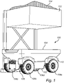
- Fig. 1 schematically illustrates a load carrying vehicle 100 in the form of a hauler.
- the load carrying vehicle 100 comprises a chassis 102, a load carrying container 104 connected to the chassis 102, a plurality of wheels 106a-d, a suspension arrangement 108 coupling the wheels 106a-d to the chassis 102.
- the suspension arrangement 108 is configured to controllably lower the container 104 such that the container 104 makes contact with at least two of the wheels 106a-d.
- the container 104 may be tiltable in relation to the chassis 102 using hydraulic cylinders, so that the load can be tipped at a drop-off location.
- the container 104 is configured so that four fenders 110 of the container 104 make contact with a corresponding wheel.
- the fenders 110 are preferably reinforced to be able to withstand the forces acting on the container 104 when the load is dropped thereon.
- the suspension arrangement 108 is controlled to lower the container 104 so that the container 104 contacts the wheels 106a-d and so that the full weight of the container 104 is thereby carried directly by the wheels 106a-d, and not by the chassis 102 and the suspension arrangement 108 in itself. Thereby, it is the tires and rims of the wheels 106 a-d that absorb any shocks occurring when dropping the load onto the container 104.
- Fig. 1 further illustrates that the load carrying vehicle 100 is located under a loading station 112, where a full container load of material 114 can be dropped into the container 104 in one pass.
- the container 104 may also be filled by any other type of loading arrangement, such as a mining shovel or the like.
- the illustrated load carrying vehicle 100 is an autonomous vehicle. However, various embodiments of the described invention are equally applicable for manually controlled or semi-autonomous vehicles.
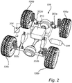
- a suspension arrangement 108 is illustrated.
- the illustrated suspension arrangement 108 is a hydraulic suspension arrangement comprising a plurality of hydraulic springs 202a-d, here one hydraulic spring for each of the four wheels 106a-d.
- the hydraulic spring may be embodied by and/or comprise a hydraulic cylinder as illustrated in Fig. 2 .
- the hydraulic cylinders 202a-d connect each wheel to the chassis 102 which in turn is connected to the container 104.
- the suspension arrangement 108 further comprises at least one hydraulic accumulator 204 connected to the hydraulic cylinders 202a-d, a hydraulic pump 206 connected to the hydraulic cylinders 202a-d and a hydraulic control system 210 configured to control the hydraulic cylinders 202a-d and any other hydraulic components of the hydraulic suspension arrangement 108 such as the hydraulic pump 206.
- the hydraulic accumulator 204 can for example be used to recuperate energy when lowering the container 104, and to provide hydraulic energy when the container 104 needs to be lifted from the wheels.
- the suspension arrangement 108 may further comprise an overflow valve configured to release pressure from the suspension arrangement 108 if a pressure in the suspension arrangement 108 exceeds a predetermined threshold value, such that the container 104 is lowered by the suspension arrangement 108.
- the overflow valve is a hydraulic overflow valve, e.g. a relief valve (not illustrated).
- the functionality of the hydraulic relief valve may for example be part of a valve block of the hydraulic control system 210.
- the described suspension arrangement 108 is a hydraulic suspension arrangement, the described functionality would also be achievable with other types of suspensions, such as pneumatic suspension, or a combination of the two.
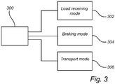
- Fig. 3 is a flow chart illustrating a method 300 of operating the load carrying described above.
- the method may comprise controlling the suspension arrangement 108 to operate in one of a plurality of operating modes.
- the method comprises controlling the suspension arrangement 108 to operate in a load receiving mode 302 in which the container 104 is in a lowered position resting on the wheels. Thereby, the container 104 is ready for loading. Moreover, the vehicle 100 is prevented from moving in the load receiving mode since the friction between the wheels 106a-d and the container 104 holds the vehicle in place.
- the suspension arrangement 108 may further be configured to elevate the container 104 at a beginning of a load sequence and to gradually lower the container 104 to a position resting on the wheels 106a-d during the load sequence.
- the described elevation may be part of the load receiving mode, or it may be defined as a separate mode where the lowering of the container 104 is controlled such that there is no risk of damage to the chassis.
- the lowering may for example be controlled by the previously described overflow valve.
- the method may further comprise operating the vehicle 100 in a braking mode 304 in which the container 104 is controlled to be in a lowered position such that a contact friction between the container 104 and the wheels 106a-d brakes the vehicle.
- the container 104 In the braking mode, the container 104 can be controlled to have an elevation which is sufficient for achieving the desired braking. Accordingly, the suspension arrangement 108 is controlled to lower the container 104 to control how much force is applied between a portion of the container 104, e.g. the fenders, and the wheels.
- the method may comprise operating the suspension arrangement 108 in a transport mode 306 in which the container 104 is controlled to be in a raised position such that there is no contact between the container 104 and the wheels 106a-d and where the weight of the container 104 is carried by the suspension arrangement.
- the position, i.e. the elevation, of the container 104 in the transport mode can be based on the amount of travel required in the suspension in the transport mode, which in turn depends of factors such as road conditions, container load, suspension properties etc.
- the position of the container 104 in the travel mode may be lower compared to in an elevated position used during or at the start of loading.
- the above described elevated position of the container 104 may be a maximum elevated position, utilizing the full extension of the hydraulic cylinders.
Landscapes
- Engineering & Computer Science (AREA)
- Mechanical Engineering (AREA)
- Health & Medical Sciences (AREA)
- Public Health (AREA)
- Transportation (AREA)
- Vehicle Body Suspensions (AREA)
Abstract
Description
- The invention relates to a load carrying vehicle adapted to receive heavy loads and to a method for controlling such a load carrying vehicle. In particular, the method and system relate to a suspension arrangement of a load carrying vehicle.
- The invention is applicable on load carrying vehicles within the fields of industrial construction machines or construction equipment, in particular dumpers, haulers, articulated haulers and the like. Although the invention will be described with respect to a hauler, the invention is not restricted to this particular machine, but may also be used in other load carrying vehicles having a container.
- In connection with transportation of heavy loads, e.g. in construction work, work machines are frequently used. A work machine may be operated with large and heavy loads in areas where there are no roads, for example for transports in connection with road or tunnel building, sand pits, mines and similar environments.
- Load carrying work machines such as an articulated hauler or dumper are typically used to transport heavy loads shorter distances and over rough terrain. Current load carrying vehicles have containers that need to be strongly dimensioned in order to be able to receive dumped loads, e.g. up to 60 tons per load from a cable-operated excavator., meaning that the container needs to be able to withstand the increased stress resulting from dumping a heavy load onto the container.
- However, the construction required to withstand the stress during loading results in a high vehicle weight which is higher than if the vehicle was dimensioned to only transport the load. The high weight in turn leads to a higher fuel consumption. Accordingly, it is desirable to reduce the vehicle weight without affecting the load carrying capacity of the vehicle.
- An object of the invention is to provide an improved load carrying vehicle capable of receiving heavy loads.
- According to a first aspect of the invention, there is provided a load carrying vehicle comprising: a chassis; a load carrying container connected to the chassis; a plurality of wheels; a suspension arrangement coupling the wheels to the chassis; wherein the suspension arrangement is configured to controllably lower the container such that the container makes contact with at least two wheels.
- In the present context, the chassis comprises the structural frame of the vehicle, and the load carrying container may for example be connected to the chassis so that the container can be tilted in relation to the chassis when tipping a load. The tilt can for example be achieved by dedicated hydraulic tilt cylinders located between the chassis and the container. In such an implementation, the container may be connected to the chassis by two joints allowing the container to be tilted, and when the container is in a horizontal position, it may rest on and be supported by the chassis at one or more points.
- In the described load carrying vehicle, a controllable suspension arrangement couples the wheels to the chassis, meaning that the weight of the chassis, and thereby of the container, is transferred to the wheels via the suspension arrangement when the suspension arrangement is in a transport mode which can be considered to be the normal operating mode. Moreover, the suspension arrangement is configured to controllably lower the container such that the container makes contact with at least two wheels. Thereby, some or all of the weight of the chassis and the container is carried directly by the wheels, and the weight of the container does not burden the chassis.
- The present invention is based on the realization that a load carrying vehicle where the weight of the container can be carried by the wheels instead of the chassis, in particular when loading the vehicle, can be made with a lighter chassis. Thereby, manufacturing costs can be lowered, and the fuel efficiency of the vehicle can be improved without sacrificing reliability.
- According to one embodiment of the invention, the container is configured to make contact with an opposing pair of wheels. This prevents the vehicle from tilting during loading and also ensures that the load can be carried equally on both sides of the vehicle. Moreover, for a vehicle where the container is located above four or more wheels, the container may rest evenly on all wheels. This can be achieved by a suspension arrangement which is capable of lowering the container and the chassis in relation to all wheels of the vehicle. The term "opposing wheels" is here used to describe two wheels arranged on opposite sides of a vehicle, such as a left rear wheel and a right rear wheel.
- According to one embodiment of the invention, a portion of the container configured to make contact with a corresponding wheel is advantageously a fender of the container which is arranged and configured to make contact with a tire of a corresponding wheel. It is advantageous to use the fenders since it would only require minor modifications of existing container designs. Moreover, the fenders or other portions of the container arranged to make contact with the tires may be suitably reinforced to withstand the forces acting on the container during loading.
- According to one embodiment of the invention, the vehicle is configured to operate in a load receiving mode in which the container is in a lowered position resting on the wheels. In the load receiving mode, the container can be assumed to be in a position so that little or no weight is carried by the suspension arrangement, thereby reducing or eliminating the load carried by the chassis.
- According to one embodiment of the invention, the suspension arrangement is further configured to, in the load receiving mode, elevate the container at a beginning of a load sequence and to gradually lower the container to a position resting on the wheels during the load sequence. In the present context, the load sequence can be described to include a first action where the container is elevated. However, the container may already be in an elevated position so that the load sequence begins with the container already being elevated. In either case, in an embodiment where the container is in an elevated position when the container receives the load, the suspension arrangement is configured to lower the container onto the wheels of the vehicle as the weight of the load in the container increases or passes a certain threshold value. The speed of the lowering is preferably limited such that the container does not abruptly come down onto the tires. On the other hand, the speed of lowering is preferably not so low so that the full weight of the container and load is taken by the chassis for an extended time period.
- According to one embodiment of the invention, the suspension arrangement comprises an overflow valve configured to release pressure from the suspension arrangement if a pressure in the suspension arrangement exceeds a predetermined threshold value, such that the container is lowered by the suspension arrangement. The overflow valve is preferably dimensioned such that the container is lowered well before there is a risk that the chassis or suspension arrangement is damaged by an excessive load on the container.
- According to one embodiment of the invention, the vehicle is further configured to operate in a braking mode in which the container is controlled to be in a lowered position such that a contact frictional force between the container and the wheels brakes the vehicle. By means of the controllable suspension arrangement, the brakes of the vehicle can be relieved, which may be advantageous in long downhill travels or for heavy loads.
- According to one embodiment of the invention, the vehicle is further configured to operate in a transport mode in which the container is controlled to be in a raised position such that there is no contact between the container and the wheels and where the weight of the container is carried by the suspension arrangement.
- According to one embodiment of the invention, the suspension arrangement may be a hydraulic suspension arrangement comprising a plurality of hydraulic springs. The hydraulic suspension arrangement may then comprise a plurality of hydraulic cylinders connecting each wheel to the chassis, at least one hydraulic accumulator connected to the hydraulic cylinders, a hydraulic pump connected to the hydraulic cylinders and a hydraulic control system configured to control the hydraulic cylinders.
- According to one embodiment of the invention, the load carrying vehicle may be an autonomous vehicle.
- According to a second aspect of the invention, there is provided a method of operating a load carrying vehicle comprising: a chassis, a load carrying container connected to the chassis; a plurality of wheels and a controllable suspension arrangement configured to couple the wheels to the chassis, the method comprising: in a load receiving mode, controlling the suspension arrangement to lower the container such that the container rests on at least two wheels of the vehicle.
- According to one embodiment of the invention, the method further comprises, in the load receiving mode, elevating the container at a beginning of a load sequence and gradually lowering the container to a position resting on the wheels during the load sequence.
- According to one embodiment of the invention, the method further comprises, in a transport mode, controlling the suspension arrangement to be in a raised position such that there is no contact between the container and the wheels and where the weight of the container is carried by the suspension arrangement.
- According to one embodiment of the invention, the method further comprises, in a braking mode, controlling the suspension arrangement to be in a lowered position such that a contact friction between the container and the wheels brakes the vehicle.
- Further effects and features of this second aspect of the present invention are largely analogous to those described above in connection with the first aspect of the invention.
- Further advantages and advantageous features of the invention are disclosed in the following description and in the dependent claims.
- With reference to the appended drawings, below follows a more detailed description of embodiments of the invention cited as examples.
- In the drawings:
-
Fig. 1 is a schematic illustration of a load carrying vehicle according to an embodiment of the invention, -
Fig. 2 is a schematic illustration of a suspension arrangement of a load carrying vehicle according to an embodiment of the invention, and -
Fig. 3 is a flow chart outlining steps of a method according to an embodiment of the invention. - In the present detailed description, various embodiments of a load carrying vehicle and a method for controlling the load carrying vehicle according to the present invention are mainly discussed with reference to a hauler comprising a container. It should however be noted that this by no means limits the scope of the present invention since the described invention is equally applicable in other types of load carrying vehicles having a container.
-
Fig. 1 schematically illustrates aload carrying vehicle 100 in the form of a hauler. Theload carrying vehicle 100 comprises achassis 102, aload carrying container 104 connected to thechassis 102, a plurality ofwheels 106a-d, asuspension arrangement 108 coupling thewheels 106a-d to thechassis 102. Thesuspension arrangement 108 is configured to controllably lower thecontainer 104 such that thecontainer 104 makes contact with at least two of thewheels 106a-d. Thecontainer 104 may be tiltable in relation to thechassis 102 using hydraulic cylinders, so that the load can be tipped at a drop-off location. - In the illustrated example, the
container 104 is configured so that fourfenders 110 of thecontainer 104 make contact with a corresponding wheel. Thefenders 110 are preferably reinforced to be able to withstand the forces acting on thecontainer 104 when the load is dropped thereon. In the illustrated embodiment, thesuspension arrangement 108 is controlled to lower thecontainer 104 so that thecontainer 104 contacts thewheels 106a-d and so that the full weight of thecontainer 104 is thereby carried directly by thewheels 106a-d, and not by thechassis 102 and thesuspension arrangement 108 in itself. Thereby, it is the tires and rims of the wheels 106 a-d that absorb any shocks occurring when dropping the load onto thecontainer 104. -
Fig. 1 further illustrates that theload carrying vehicle 100 is located under aloading station 112, where a full container load ofmaterial 114 can be dropped into thecontainer 104 in one pass. Thecontainer 104 may also be filled by any other type of loading arrangement, such as a mining shovel or the like. Moreover, the illustratedload carrying vehicle 100 is an autonomous vehicle. However, various embodiments of the described invention are equally applicable for manually controlled or semi-autonomous vehicles. - In
Fig. 2 , an example embodiment of asuspension arrangement 108 is illustrated. In particular, the illustratedsuspension arrangement 108 is a hydraulic suspension arrangement comprising a plurality ofhydraulic springs 202a-d, here one hydraulic spring for each of the fourwheels 106a-d. The hydraulic spring may be embodied by and/or comprise a hydraulic cylinder as illustrated inFig. 2 . Thehydraulic cylinders 202a-d connect each wheel to thechassis 102 which in turn is connected to thecontainer 104. Thesuspension arrangement 108 further comprises at least one hydraulic accumulator 204 connected to thehydraulic cylinders 202a-d, ahydraulic pump 206 connected to thehydraulic cylinders 202a-d and ahydraulic control system 210 configured to control thehydraulic cylinders 202a-d and any other hydraulic components of thehydraulic suspension arrangement 108 such as thehydraulic pump 206. The hydraulic accumulator 204 can for example be used to recuperate energy when lowering thecontainer 104, and to provide hydraulic energy when thecontainer 104 needs to be lifted from the wheels. - The
suspension arrangement 108 may further comprise an overflow valve configured to release pressure from thesuspension arrangement 108 if a pressure in thesuspension arrangement 108 exceeds a predetermined threshold value, such that thecontainer 104 is lowered by thesuspension arrangement 108. In the illustratedhydraulic suspension arrangement 108, the overflow valve is a hydraulic overflow valve, e.g. a relief valve (not illustrated). The functionality of the hydraulic relief valve may for example be part of a valve block of thehydraulic control system 210. Even though the describedsuspension arrangement 108 is a hydraulic suspension arrangement, the described functionality would also be achievable with other types of suspensions, such as pneumatic suspension, or a combination of the two. -
Fig. 3 is a flow chart illustrating amethod 300 of operating the load carrying described above. The method may comprise controlling thesuspension arrangement 108 to operate in one of a plurality of operating modes. The method comprises controlling thesuspension arrangement 108 to operate in aload receiving mode 302 in which thecontainer 104 is in a lowered position resting on the wheels. Thereby, thecontainer 104 is ready for loading. Moreover, thevehicle 100 is prevented from moving in the load receiving mode since the friction between thewheels 106a-d and thecontainer 104 holds the vehicle in place. - The
suspension arrangement 108 may further be configured to elevate thecontainer 104 at a beginning of a load sequence and to gradually lower thecontainer 104 to a position resting on thewheels 106a-d during the load sequence. The described elevation may be part of the load receiving mode, or it may be defined as a separate mode where the lowering of thecontainer 104 is controlled such that there is no risk of damage to the chassis. The lowering may for example be controlled by the previously described overflow valve. - The method may further comprise operating the
vehicle 100 in abraking mode 304 in which thecontainer 104 is controlled to be in a lowered position such that a contact friction between thecontainer 104 and thewheels 106a-d brakes the vehicle. In the braking mode, thecontainer 104 can be controlled to have an elevation which is sufficient for achieving the desired braking. Accordingly, thesuspension arrangement 108 is controlled to lower thecontainer 104 to control how much force is applied between a portion of thecontainer 104, e.g. the fenders, and the wheels. - Moreover, the method may comprise operating the
suspension arrangement 108 in atransport mode 306 in which thecontainer 104 is controlled to be in a raised position such that there is no contact between thecontainer 104 and thewheels 106a-d and where the weight of thecontainer 104 is carried by the suspension arrangement. The position, i.e. the elevation, of thecontainer 104 in the transport mode can be based on the amount of travel required in the suspension in the transport mode, which in turn depends of factors such as road conditions, container load, suspension properties etc. - Moreover, the position of the
container 104 in the travel mode may be lower compared to in an elevated position used during or at the start of loading. The above described elevated position of thecontainer 104 may be a maximum elevated position, utilizing the full extension of the hydraulic cylinders. - It is to be understood that the present invention is not limited to the embodiments described above and illustrated in the drawings; rather, the skilled person will recognize that many changes and modifications may be made within the scope of the appended claims.
Claims (15)
- A load carrying vehicle (100) comprising:a chassis (102);a load carrying container (104) connected to the chassis;a plurality of wheels (106a-d);a suspension arrangement (108) coupling the wheels to the chassis;wherein the suspension arrangement is configured to controllably lower the container such that the container makes contact with at least two wheels.
- The load carrying vehicle according to claim 1, wherein the container is configured to make contact with an opposing pair of wheels.
- The load carrying vehicle according to claim 1 or 2, wherein a portion of the container configured to make contact with a corresponding wheel is a fender (110) of the container arranged and configured to make contact with a tire of a corresponding wheel.
- The load carrying vehicle according to any one of the preceding claims, wherein the vehicle is configured to operate in a load receiving mode in which the container is in a lowered position resting on the wheels.
- The load carrying vehicle according to claim 4, wherein the suspension arrangement is further configured to, in the load receiving mode, elevate the container at a beginning of a load sequence and to gradually lower the container to a position resting on the wheels during the load sequence.
- The load carrying vehicle according to claim 5, wherein the suspension arrangement comprises an overflow valve configured to release pressure from the suspension arrangement if a pressure in the suspension arrangement exceeds a predetermined threshold value, such that the container is lowered by the suspension arrangement.
- The load carrying vehicle according to any one of the preceding claims, wherein the vehicle is configured to operate in a braking mode in which the container is controlled to be in a lowered position such that a contact frictional force between the container and the wheels brakes the vehicle.
- The load carrying vehicle according to any one of the preceding claims, wherein the vehicle is configured to operate in a transport mode in which the container is controlled to be in a raised position such that there is no contact between the container and the wheels and such that the weight of the container is carried by the suspension arrangement.
- The load carrying vehicle according to any one of the preceding claims, wherein the suspension arrangement is a hydraulic suspension arrangement comprising a plurality of hydraulic springs.
- The load carrying vehicle according to claim 9, wherein the hydraulic suspension arrangement (108) comprises a plurality of hydraulic cylinders (202a-d) connecting each wheel to the chassis, at least one hydraulic accumulator (204) connected to the hydraulic cylinders, a hydraulic pump (206) connected to the hydraulic cylinders and a hydraulic control system (210) configured to control the hydraulic cylinders.
- The load carrying vehicle according to any one of the preceding claims, wherein the vehicle is an autonomous vehicle.
- Method of operating a load carrying vehicle (100) comprising: a chassis (102), a load carrying container (104) connected to the chassis; a plurality of wheels (106a-d) and a controllable suspension arrangement (108) configured to couple the wheels to the chassis, the method comprising:
in a load receiving mode (302), controlling the suspension arrangement to lower the container such that the container rests on at least two wheels of the vehicle. - The method according to claim 12, further comprising, in the load receiving mode, elevating the container at a beginning of a load sequence and gradually lowering the container to a position resting on the wheels during the load sequence.
- The method according to claim 12 or 13, further comprising, in a transport mode (306), controlling the suspension arrangement to be in a raised position such that there is no contact between the container and the wheels and where the weight of the container is carried by the suspension arrangement.
- The method according to any one of claims 12 to 14, further comprising, in a braking mode (304), controlling the suspension arrangement to be in a lowered position such that a contact friction between the container and the wheels brakes the vehicle.
Priority Applications (3)
| Application Number | Priority Date | Filing Date | Title |
|---|---|---|---|
| EP20207495.1A EP4000972B1 (en) | 2020-11-13 | 2020-11-13 | Load carrying vehicle having a container and method for controlling the load carrying vehicle |
| CN202111306480.0A CN114475399A (en) | 2020-11-13 | 2021-11-05 | Load-carrying vehicle with a loading compartment and method for controlling a load-carrying vehicle |
| US17/525,288 US11584186B2 (en) | 2020-11-13 | 2021-11-12 | Load carrying vehicle having a container and method for controlling the load carrying vehicle |
Applications Claiming Priority (1)
| Application Number | Priority Date | Filing Date | Title |
|---|---|---|---|
| EP20207495.1A EP4000972B1 (en) | 2020-11-13 | 2020-11-13 | Load carrying vehicle having a container and method for controlling the load carrying vehicle |
Publications (3)
| Publication Number | Publication Date |
|---|---|
| EP4000972A1 true EP4000972A1 (en) | 2022-05-25 |
| EP4000972B1 EP4000972B1 (en) | 2023-10-11 |
| EP4000972C0 EP4000972C0 (en) | 2023-10-11 |
Family
ID=73448905
Family Applications (1)
| Application Number | Title | Priority Date | Filing Date |
|---|---|---|---|
| EP20207495.1A Active EP4000972B1 (en) | 2020-11-13 | 2020-11-13 | Load carrying vehicle having a container and method for controlling the load carrying vehicle |
Country Status (3)
| Country | Link |
|---|---|
| US (1) | US11584186B2 (en) |
| EP (1) | EP4000972B1 (en) |
| CN (1) | CN114475399A (en) |
Citations (2)
| Publication number | Priority date | Publication date | Assignee | Title |
|---|---|---|---|---|
| WO2004106110A1 (en) * | 2003-06-03 | 2004-12-09 | Gemco Mobile Systems B.V. | Wheel suspension and vehicle |
| US20110035104A1 (en) * | 2009-04-15 | 2011-02-10 | Judson Smith | Suspension conversion method and apparatus |
Family Cites Families (15)
| Publication number | Priority date | Publication date | Assignee | Title |
|---|---|---|---|---|
| US3106410A (en) | 1961-09-15 | 1963-10-08 | Truck Equipment Co Inc | Tilt preventing structure for side loaded vehicles |
| JPH0825376B2 (en) * | 1985-05-20 | 1996-03-13 | 日野自動車工業株式会社 | Truck bed height adjuster |
| US5165838A (en) * | 1990-09-06 | 1992-11-24 | Teledyne Industries, Inc. | Vehicle for transporting loads |
| JP3046817B1 (en) * | 1999-03-24 | 2000-05-29 | 明 恵比須 | Vehicle suspension method and apparatus |
| JP2004359181A (en) * | 2003-06-06 | 2004-12-24 | Toyota Motor Corp | Vehicle suspension device |
| JP2007290608A (en) * | 2006-04-26 | 2007-11-08 | Tokyu Car Corp | Yard carrier |
| US8157499B1 (en) | 2008-09-15 | 2012-04-17 | Jack Jones | Containerized freight system |
| CN102529629B (en) * | 2011-12-30 | 2014-04-02 | 中国农业大学 | Vehicle chassis height regulating suspension and vehicle with same |
| CN104760481B (en) * | 2015-03-06 | 2017-04-05 | 三江瓦力特特种车辆有限公司 | A kind of electric drive hydraulic pressure independent suspension coiled tubing chassis |
| US10479256B2 (en) * | 2016-03-03 | 2019-11-19 | 2222035 Ontario Inc. | System and method for loading a container for transport |
| CN109094316A (en) * | 2018-10-11 | 2018-12-28 | 营山县臻安机电科技研究所 | A kind of full automatic balance type transverse spring |
| CN211519176U (en) * | 2019-12-06 | 2020-09-18 | 徐工集团工程机械股份有限公司 | Oil gas suspension device of remote control vehicle and remote control vehicle |
| CN110962723A (en) * | 2019-12-20 | 2020-04-07 | 山东科技大学 | Lifting type mountain transportation moped and application thereof |
| CN111267573A (en) * | 2020-01-20 | 2020-06-12 | 郑州宇通重工有限公司 | Vehicle antiskid control method and system, computer readable storage medium and vehicle |
| CN111546833B (en) * | 2020-05-28 | 2024-03-12 | 上海西井科技股份有限公司 | Adaptive load-carrying vehicle, method, apparatus and storage medium |
-
2020
- 2020-11-13 EP EP20207495.1A patent/EP4000972B1/en active Active
-
2021
- 2021-11-05 CN CN202111306480.0A patent/CN114475399A/en active Pending
- 2021-11-12 US US17/525,288 patent/US11584186B2/en active Active
Patent Citations (2)
| Publication number | Priority date | Publication date | Assignee | Title |
|---|---|---|---|---|
| WO2004106110A1 (en) * | 2003-06-03 | 2004-12-09 | Gemco Mobile Systems B.V. | Wheel suspension and vehicle |
| US20110035104A1 (en) * | 2009-04-15 | 2011-02-10 | Judson Smith | Suspension conversion method and apparatus |
Also Published As
| Publication number | Publication date |
|---|---|
| EP4000972B1 (en) | 2023-10-11 |
| US11584186B2 (en) | 2023-02-21 |
| US20220153082A1 (en) | 2022-05-19 |
| EP4000972C0 (en) | 2023-10-11 |
| CN114475399A (en) | 2022-05-13 |
Similar Documents
| Publication | Publication Date | Title |
|---|---|---|
| US8086370B2 (en) | Load controlled stabilizer system | |
| US9174562B2 (en) | Transport vehicle | |
| JPWO2008099691A1 (en) | Transport vehicle | |
| JP2013169931A (en) | Transport vehicle | |
| EP1188612A2 (en) | Improvements in and relating to tipping trailers | |
| CN108698532A (en) | transport vehicle | |
| CN106457951A (en) | Pneumatic control system for a heavy-duty vehicle | |
| JP2013028306A (en) | Conveying vehicle | |
| JP6473240B2 (en) | Transportation vehicle | |
| US4375903A (en) | Vehicle suspension system augmenter | |
| US3203735A (en) | Fluid operated tilting dump truck stabilizer | |
| US11440369B2 (en) | Pick and carry crane suspension | |
| US11584186B2 (en) | Load carrying vehicle having a container and method for controlling the load carrying vehicle | |
| US7841604B2 (en) | Detachable trailing tag axle | |
| EP0761589B1 (en) | A lifting mechanism for road vehicles | |
| GB2202497A (en) | Tipping vehicles, and their stabilisation | |
| US11981241B2 (en) | Method for determining a status of a dump body arrangement | |
| CN215154170U (en) | Tipper facial make-up that stability is high | |
| JP2528067Y2 (en) | Undercarriage type vehicle | |
| US20250074284A1 (en) | Dump truck | |
| CN207997790U (en) | A kind of dumper | |
| JPH01220700A (en) | Shock absober for fork lift | |
| JPH0732843A (en) | Attitude control device for work vehicle | |
| JPH0351222Y2 (en) | ||
| IE950175A1 (en) | A lifting mechanism |
Legal Events
| Date | Code | Title | Description |
|---|---|---|---|
| PUAI | Public reference made under article 153(3) epc to a published international application that has entered the european phase |
Free format text: ORIGINAL CODE: 0009012 |
|
| STAA | Information on the status of an ep patent application or granted ep patent |
Free format text: STATUS: THE APPLICATION HAS BEEN PUBLISHED |
|
| AK | Designated contracting states |
Kind code of ref document: A1 Designated state(s): AL AT BE BG CH CY CZ DE DK EE ES FI FR GB GR HR HU IE IS IT LI LT LU LV MC MK MT NL NO PL PT RO RS SE SI SK SM TR |
|
| STAA | Information on the status of an ep patent application or granted ep patent |
Free format text: STATUS: REQUEST FOR EXAMINATION WAS MADE |
|
| 17P | Request for examination filed |
Effective date: 20221110 |
|
| RBV | Designated contracting states (corrected) |
Designated state(s): AL AT BE BG CH CY CZ DE DK EE ES FI FR GB GR HR HU IE IS IT LI LT LU LV MC MK MT NL NO PL PT RO RS SE SI SK SM TR |
|
| GRAP | Despatch of communication of intention to grant a patent |
Free format text: ORIGINAL CODE: EPIDOSNIGR1 |
|
| STAA | Information on the status of an ep patent application or granted ep patent |
Free format text: STATUS: GRANT OF PATENT IS INTENDED |
|
| INTG | Intention to grant announced |
Effective date: 20230526 |
|
| GRAS | Grant fee paid |
Free format text: ORIGINAL CODE: EPIDOSNIGR3 |
|
| GRAA | (expected) grant |
Free format text: ORIGINAL CODE: 0009210 |
|
| STAA | Information on the status of an ep patent application or granted ep patent |
Free format text: STATUS: THE PATENT HAS BEEN GRANTED |
|
| AK | Designated contracting states |
Kind code of ref document: B1 Designated state(s): AL AT BE BG CH CY CZ DE DK EE ES FI FR GB GR HR HU IE IS IT LI LT LU LV MC MK MT NL NO PL PT RO RS SE SI SK SM TR |
|
| REG | Reference to a national code |
Ref country code: GB Ref legal event code: FG4D |
|
| REG | Reference to a national code |
Ref country code: CH Ref legal event code: EP |
|
| REG | Reference to a national code |
Ref country code: DE Ref legal event code: R096 Ref document number: 602020018974 Country of ref document: DE |
|
| REG | Reference to a national code |
Ref country code: IE Ref legal event code: FG4D |
|
| U01 | Request for unitary effect filed |
Effective date: 20231012 |
|
| U07 | Unitary effect registered |
Designated state(s): AT BE BG DE DK EE FI FR IT LT LU LV MT NL PT SE SI Effective date: 20231020 |
|
| U20 | Renewal fee for the european patent with unitary effect paid |
Year of fee payment: 4 Effective date: 20231024 |
|
| PG25 | Lapsed in a contracting state [announced via postgrant information from national office to epo] |
Ref country code: GR Free format text: LAPSE BECAUSE OF FAILURE TO SUBMIT A TRANSLATION OF THE DESCRIPTION OR TO PAY THE FEE WITHIN THE PRESCRIBED TIME-LIMIT Effective date: 20240112 |
|
| PG25 | Lapsed in a contracting state [announced via postgrant information from national office to epo] |
Ref country code: IS Free format text: LAPSE BECAUSE OF FAILURE TO SUBMIT A TRANSLATION OF THE DESCRIPTION OR TO PAY THE FEE WITHIN THE PRESCRIBED TIME-LIMIT Effective date: 20240211 |
|
| PG25 | Lapsed in a contracting state [announced via postgrant information from national office to epo] |
Ref country code: ES Free format text: LAPSE BECAUSE OF FAILURE TO SUBMIT A TRANSLATION OF THE DESCRIPTION OR TO PAY THE FEE WITHIN THE PRESCRIBED TIME-LIMIT Effective date: 20231011 |
|
| PG25 | Lapsed in a contracting state [announced via postgrant information from national office to epo] |
Ref country code: IS Free format text: LAPSE BECAUSE OF FAILURE TO SUBMIT A TRANSLATION OF THE DESCRIPTION OR TO PAY THE FEE WITHIN THE PRESCRIBED TIME-LIMIT Effective date: 20240211 Ref country code: GR Free format text: LAPSE BECAUSE OF FAILURE TO SUBMIT A TRANSLATION OF THE DESCRIPTION OR TO PAY THE FEE WITHIN THE PRESCRIBED TIME-LIMIT Effective date: 20240112 Ref country code: ES Free format text: LAPSE BECAUSE OF FAILURE TO SUBMIT A TRANSLATION OF THE DESCRIPTION OR TO PAY THE FEE WITHIN THE PRESCRIBED TIME-LIMIT Effective date: 20231011 |
|
| PG25 | Lapsed in a contracting state [announced via postgrant information from national office to epo] |
Ref country code: RS Free format text: LAPSE BECAUSE OF FAILURE TO SUBMIT A TRANSLATION OF THE DESCRIPTION OR TO PAY THE FEE WITHIN THE PRESCRIBED TIME-LIMIT Effective date: 20231011 Ref country code: PL Free format text: LAPSE BECAUSE OF FAILURE TO SUBMIT A TRANSLATION OF THE DESCRIPTION OR TO PAY THE FEE WITHIN THE PRESCRIBED TIME-LIMIT Effective date: 20231011 Ref country code: NO Free format text: LAPSE BECAUSE OF FAILURE TO SUBMIT A TRANSLATION OF THE DESCRIPTION OR TO PAY THE FEE WITHIN THE PRESCRIBED TIME-LIMIT Effective date: 20240111 Ref country code: HR Free format text: LAPSE BECAUSE OF FAILURE TO SUBMIT A TRANSLATION OF THE DESCRIPTION OR TO PAY THE FEE WITHIN THE PRESCRIBED TIME-LIMIT Effective date: 20231011 |
|
| REG | Reference to a national code |
Ref country code: CH Ref legal event code: PL |
|
| REG | Reference to a national code |
Ref country code: DE Ref legal event code: R097 Ref document number: 602020018974 Country of ref document: DE |
|
| PG25 | Lapsed in a contracting state [announced via postgrant information from national office to epo] |
Ref country code: CH Free format text: LAPSE BECAUSE OF NON-PAYMENT OF DUE FEES Effective date: 20231130 |
|
| PG25 | Lapsed in a contracting state [announced via postgrant information from national office to epo] |
Ref country code: CZ Free format text: LAPSE BECAUSE OF FAILURE TO SUBMIT A TRANSLATION OF THE DESCRIPTION OR TO PAY THE FEE WITHIN THE PRESCRIBED TIME-LIMIT Effective date: 20231011 |
|
| PG25 | Lapsed in a contracting state [announced via postgrant information from national office to epo] |
Ref country code: SK Free format text: LAPSE BECAUSE OF FAILURE TO SUBMIT A TRANSLATION OF THE DESCRIPTION OR TO PAY THE FEE WITHIN THE PRESCRIBED TIME-LIMIT Effective date: 20231011 |
|
| PG25 | Lapsed in a contracting state [announced via postgrant information from national office to epo] |
Ref country code: SM Free format text: LAPSE BECAUSE OF FAILURE TO SUBMIT A TRANSLATION OF THE DESCRIPTION OR TO PAY THE FEE WITHIN THE PRESCRIBED TIME-LIMIT Effective date: 20231011 Ref country code: SK Free format text: LAPSE BECAUSE OF FAILURE TO SUBMIT A TRANSLATION OF THE DESCRIPTION OR TO PAY THE FEE WITHIN THE PRESCRIBED TIME-LIMIT Effective date: 20231011 Ref country code: RO Free format text: LAPSE BECAUSE OF FAILURE TO SUBMIT A TRANSLATION OF THE DESCRIPTION OR TO PAY THE FEE WITHIN THE PRESCRIBED TIME-LIMIT Effective date: 20231011 Ref country code: CZ Free format text: LAPSE BECAUSE OF FAILURE TO SUBMIT A TRANSLATION OF THE DESCRIPTION OR TO PAY THE FEE WITHIN THE PRESCRIBED TIME-LIMIT Effective date: 20231011 Ref country code: CH Free format text: LAPSE BECAUSE OF NON-PAYMENT OF DUE FEES Effective date: 20231130 |
|
| PLBE | No opposition filed within time limit |
Free format text: ORIGINAL CODE: 0009261 |
|
| STAA | Information on the status of an ep patent application or granted ep patent |
Free format text: STATUS: NO OPPOSITION FILED WITHIN TIME LIMIT |
|
| PG25 | Lapsed in a contracting state [announced via postgrant information from national office to epo] |
Ref country code: MC Free format text: LAPSE BECAUSE OF FAILURE TO SUBMIT A TRANSLATION OF THE DESCRIPTION OR TO PAY THE FEE WITHIN THE PRESCRIBED TIME-LIMIT Effective date: 20231011 |
|
| PG25 | Lapsed in a contracting state [announced via postgrant information from national office to epo] |
Ref country code: MC Free format text: LAPSE BECAUSE OF FAILURE TO SUBMIT A TRANSLATION OF THE DESCRIPTION OR TO PAY THE FEE WITHIN THE PRESCRIBED TIME-LIMIT Effective date: 20231011 |
|
| REG | Reference to a national code |
Ref country code: IE Ref legal event code: MM4A |
|
| 26N | No opposition filed |
Effective date: 20240712 |
|
| PG25 | Lapsed in a contracting state [announced via postgrant information from national office to epo] |
Ref country code: IE Free format text: LAPSE BECAUSE OF NON-PAYMENT OF DUE FEES Effective date: 20231113 |
|
| PG25 | Lapsed in a contracting state [announced via postgrant information from national office to epo] |
Ref country code: IE Free format text: LAPSE BECAUSE OF NON-PAYMENT OF DUE FEES Effective date: 20231113 |
|
| U20 | Renewal fee for the european patent with unitary effect paid |
Year of fee payment: 5 Effective date: 20241127 |
|
| GBPC | Gb: european patent ceased through non-payment of renewal fee |
Effective date: 20241113 |
|
| PG25 | Lapsed in a contracting state [announced via postgrant information from national office to epo] |
Ref country code: CY Free format text: LAPSE BECAUSE OF FAILURE TO SUBMIT A TRANSLATION OF THE DESCRIPTION OR TO PAY THE FEE WITHIN THE PRESCRIBED TIME-LIMIT; INVALID AB INITIO Effective date: 20201113 |
|
| PG25 | Lapsed in a contracting state [announced via postgrant information from national office to epo] |
Ref country code: HU Free format text: LAPSE BECAUSE OF FAILURE TO SUBMIT A TRANSLATION OF THE DESCRIPTION OR TO PAY THE FEE WITHIN THE PRESCRIBED TIME-LIMIT; INVALID AB INITIO Effective date: 20201113 |
|
| PG25 | Lapsed in a contracting state [announced via postgrant information from national office to epo] |
Ref country code: GB Free format text: LAPSE BECAUSE OF NON-PAYMENT OF DUE FEES Effective date: 20241113 |
|
| PG25 | Lapsed in a contracting state [announced via postgrant information from national office to epo] |
Ref country code: TR Free format text: LAPSE BECAUSE OF FAILURE TO SUBMIT A TRANSLATION OF THE DESCRIPTION OR TO PAY THE FEE WITHIN THE PRESCRIBED TIME-LIMIT Effective date: 20231011 |
|
| U20 | Renewal fee for the european patent with unitary effect paid |
Year of fee payment: 6 Effective date: 20251126 |