EP4000946A1 - A writing instrument having a retractable writing tip and a retractable eraser - Google Patents
A writing instrument having a retractable writing tip and a retractable eraser Download PDFInfo
- Publication number
- EP4000946A1 EP4000946A1 EP20306437.3A EP20306437A EP4000946A1 EP 4000946 A1 EP4000946 A1 EP 4000946A1 EP 20306437 A EP20306437 A EP 20306437A EP 4000946 A1 EP4000946 A1 EP 4000946A1
- Authority
- EP
- European Patent Office
- Prior art keywords
- eraser
- writing
- cam
- helical
- helical cam
- Prior art date
- Legal status (The legal status is an assumption and is not a legal conclusion. Google has not performed a legal analysis and makes no representation as to the accuracy of the status listed.)
- Granted
Links
Images



Classifications
-
- B—PERFORMING OPERATIONS; TRANSPORTING
- B43—WRITING OR DRAWING IMPLEMENTS; BUREAU ACCESSORIES
- B43K—IMPLEMENTS FOR WRITING OR DRAWING
- B43K29/00—Combinations of writing implements with other articles
- B43K29/02—Combinations of writing implements with other articles with rubbers
-
- B—PERFORMING OPERATIONS; TRANSPORTING
- B43—WRITING OR DRAWING IMPLEMENTS; BUREAU ACCESSORIES
- B43K—IMPLEMENTS FOR WRITING OR DRAWING
- B43K24/00—Mechanisms for selecting, projecting, retracting or locking writing units
- B43K24/02—Mechanisms for selecting, projecting, retracting or locking writing units for locking a single writing unit in only fully projected or retracted positions
- B43K24/06—Mechanisms for selecting, projecting, retracting or locking writing units for locking a single writing unit in only fully projected or retracted positions operated by turning means
-
- B—PERFORMING OPERATIONS; TRANSPORTING
- B43—WRITING OR DRAWING IMPLEMENTS; BUREAU ACCESSORIES
- B43K—IMPLEMENTS FOR WRITING OR DRAWING
- B43K24/00—Mechanisms for selecting, projecting, retracting or locking writing units
- B43K24/10—Mechanisms for selecting, projecting, retracting or locking writing units for selecting, projecting and locking several writing units
- B43K24/14—Mechanisms for selecting, projecting, retracting or locking writing units for selecting, projecting and locking several writing units operated by turning means
- B43K24/146—Mechanisms for selecting, projecting, retracting or locking writing units for selecting, projecting and locking several writing units operated by turning means with cam control
-
- B—PERFORMING OPERATIONS; TRANSPORTING
- B43—WRITING OR DRAWING IMPLEMENTS; BUREAU ACCESSORIES
- B43L—ARTICLES FOR WRITING OR DRAWING UPON; WRITING OR DRAWING AIDS; ACCESSORIES FOR WRITING OR DRAWING
- B43L19/00—Erasers, rubbers, or erasing devices; Holders therefor
- B43L19/0056—Holders for erasers
- B43L19/0068—Hand-held holders
- B43L19/0075—Hand-held holders of the pencil type
Definitions
- the present disclosure relates to a writing instrument having a retractable writing tip and a retractable eraser disposed at the front end.
- the writing instrument may be a rotating retractable writing instrument which can protrude and retract a writing tip and an eraser.
- a writing instrument comprises a body extending along an axis, the body having a first end and a second end opposed to the first end along the axis, the first end being provided with a writing tip and with an eraser, the writing instrument further comprising a first helical cam propelling mechanism configured to move the writing tip along the axis between a retracted position and a protruded position and a second helical cam propelling mechanism configured to move the eraser along the axis between a retracted position and a protruded position, the first helical cam propelling mechanism comprising a first cam follower and a first helical cam, the second helical cam propelling mechanism comprising a second cam follower and a second helical cam, each of the first cam follower, the first helical cam, the second cam follower and the second helical cam being provided on distinct elements.
- the first end is the front end and the second end is the rear end.
- the writing tip may be a pencil tip, a pen tip, a felt tip, a ballpoint tip or any other means making it possible to write on a substrate or surface.
- Both the eraser and the writing tip can axially move with regard to the body.
- the eraser In the retracted position the eraser may be not able to be used for erasing (e.g. the eraser may be concealed within the body).
- the eraser In the protruded position the eraser may be able to be used for erasing (e.g. the eraser may protrude at least in part axially out of the body).
- the writing tip In the retracted position, the writing tip may be not able to be used for writing (e.g. the writing tip may be concealed within the body). In the protruded position the writing tip may be used for writing (e.g. the writing tip may protrude at least in part axially out of the body).
- Each of the first cam follower, the first helical cam, the second cam follower and the second helical cam is provided on an element which is distinct from any elements having the others of the first cam follower, the first helical cam, the second cam follower and the second helical cam.
- Such a writing instrument may have at least one part easily removable for refill, e.g. for replacing the eraser and/or the writing tip and/or a writing body having the writing tip and a reservoir, and/or for ink/lead refill.
- the eraser and the writing tip may be at least in part coaxial, and all or part of the eraser may be disposed around all or part of the writing tip.
- the eraser may have at least a portion forming a sleeve around the writing tip and sliding along the axis.
- the writing tip may comprise a writing end, and, when the writing instrument is seen perpendicular to the axis, the writing end may be concealed by the eraser when the eraser is in the protruded position and the writing end may be free from the eraser when the eraser is in the retracted position and the writing tip is in the protruded position.
- the writing end is the portion of the writing tip which is applied on a substrate or surface for writing.
- the eraser may have at least a portion forming a sleeve around the writing tip and sliding along the axis in order to free the writing end for writing (i.e. when the eraser is in the retracted position and the writing tip is in the protruded position) or to concealed the writing end for erasing (i.e. when the eraser is in the protruded position, the writing tip being in any position).
- the eraser may have a cylindrical portion extending along the axis.
- the sleeve of the eraser may have an axial length greater than or equal to the axial length of the portion of the writing tip which protrudes axially out of the body.
- the eraser may have a distal end, and the distal end may have a frustoconical shape.
- the first helical cam propelling mechanism and the second helical cam propelling mechanism may be configured to, when actuated together (for example in a same first rotational direction), move (for example from a starting position) the writing tip from the retracted position to the protruded position first, move the eraser from the retracted position to the protruded position after moving the writing tip from the retracted position to the protruded position, and then move both the writing tip and the eraser back to the retracted position.
- first helical cam propelling mechanism and the second helical cam propelling mechanism may be configured to be only actuated together.
- the first helical cam propelling mechanism and the second helical cam propelling mechanism may be not actuated from a starting position in a second rotational direction, opposite to the first rotational direction (i.e. the first helical cam propelling mechanism and the second helical cam propelling mechanism may be configured to block their rotation in the second rotational direction from the starting position and to allow their rotation in the first rotational direction from the starting position).
- the first helical cam propelling mechanism and the second helical cam propelling mechanism may be configured to be actuated only in the first rotational direction from the starting position.
- first helical cam propelling mechanism and the second helical cam propelling mechanism may be configured to be actuated in the second rotational direction from any other position than the starting position.
- first helical cam propelling mechanism and the second helical cam propelling mechanism
- second helical cam propelling mechanism may be actuated in the second rotational direction for moving the writing tip from the protruded position toward the retracted position.
- the second helical cam propelling mechanism and the first helical cam propelling mechanism
- the second helical cam propelling mechanism may be actuated in the second rotational direction for moving the eraser from the protruded position toward the retracted position.
- the writing tip may be retracted to an intermediate position between the protruded position and the retracted position, when the eraser is moved from the retracted position to the protruded position.
- one of the first cam follower and the first helical cam and one of the second cam follower and the second helical cam may be rotatably coupled.
- the first cam follower and the second cam follower may be rotatably coupled, the first cam follower and the second helical cam may be rotatably coupled, the first helical cam and the second cam follower may be rotatably coupled or the first helical cam and the second helical cam may be rotatably coupled.
- the body may comprise a first part and a second part, the second part being rotatable around the axis with regard to the first part and axially coupled with the first part, and the second part being rotatably coupled with one of the first cam follower and the first helical cam and one of the second cam follower and the second helical cam.
- the first part may be distinct from the second part.
- the second part may be rotatably coupled with the first cam follower and the second cam follower, the first cam follower and the second helical cam, the first helical cam and the second cam follower or the first helical cam and the second helical cam.
- the relative rotation of the first part with regard to the second part may actuate the first helical-cam propelling mechanism and the second helical-cam propelling mechanism, due to which the writing tip and/or the eraser may be moved between the retracted position and the protruded position.
- the first part may be snap-fitted with the second part.
- the first part may be removably or un-removably snap-fitted with the second part.
- the eraser may be rotatably coupled with the first part and axially slidable with regard to the first part.
- the eraser may be axially coupled with the second part and rotatable with regard to the second part.
- the writing instrument may comprise a pusher configured to push the writing tip.
- the pusher may push the writing tip directly or indirectly.
- the writing tip may be part of a writing body and the pusher may be configured to push directly the writing body.
- the pusher may extend inside the second part and be axially coupled with the second part, rotatably coupled with the eraser, rotatable with regard to the second part and axially slidable with regard to the eraser
- the second part may comprise a first portion and a second portion, the first portion is mounted with the first part, the second portion being removably coupled with the first portion.
- the first portion may be distinct from the second portion. For example, removing the second portion may allow the removal of the writing tip/writing body and/or of the eraser for refill/replacement.
- the first portion may be snap-fitted with the first part.
- the first portion may be removably or un-removably snap-fitted with the first part.
- the second portion may be removably snap-fitted or screwed with the first portion.
- the first portion may comprise one of the second cam follower and the second helical cam and the second portion may comprise one of the first cam follower and the first helical cam.
- the first portion may comprise the second cam follower and the second portion may comprise the first cam follower
- the first portion may comprise the second cam follower and the second portion may comprise the first helical cam
- the first portion may comprise the second helical cam and the second portion may comprise the first cam follower
- the first portion may comprise the second helical cam and the second portion may comprise the first cam follower
- the first portion may comprise the second helical cam and the second portion may comprise the first helical cam.
- the second portion may comprise an outer element and an inner element disposed at least in part inside the outer element, the outer element being removably coupled with the first portion, the inner element being rotatable with regard to the outer element and axially coupled with the outer element.
- the inner element may be distinct from the outer element.
- the inner element is at least in part disposed radially inside the outer element.
- the outer element is at least in part disposed radially outside the inner element.
- the inner element may be snap-fitted with the outer element.
- the inner element may be removably or un-removably snap-fitted with the outer element.
- the inner element may comprise one of the first cam follower and the first helical cam.
- the inner element may comprise the first cam follower or the first helical cam.
- the inner element may be rotatably coupled with the first portion.
- the inner element may be axially slidable with regard to the first portion.
- the writing instrument may comprise a first return spring configured to push the writing tip toward one of the retracted position and the protruded position and/or a second return spring configured to push the eraser toward one of the retracted position and the protruded position.
- first cam follower and the first helical cam may be configured to push the writing tip toward the protruded position or the retracted position and the first return spring may be configured to push the writing tip toward the retracted position or the protruded position, respectively.
- second cam follower and the second helical cam may be configured to push the eraser toward the protruded position or the retracted position and the second return spring may be configured to push the eraser toward the retracted position or the protruded position, respectively.
- the writing tip may be configured to be fed with ink.
- the ink may be an erasable ink.
- the eraser may be configured to erase the erasable ink.
- the erasable ink may be a peelable ink or a thermochromic ink and the eraser may be a peeling body or a friction body, respectively.
- a peelable ink is an ink that forms a removable layer on the substrate or surface onto which it is applied.
- a peeling body is configured to remove or peel a layer of peelable ink.
- the peeling body may be made of rubber (synthetic or natural), foam, felt, cloth, sponge, gum, silicone, etc.
- thermochromic ink is an ink that may change color as a function of the heat to which it is subjected.
- a friction body is a body configured to be rubbed over a surface, for example in order to generate heat and to cause a thermochromic ink to change color.
- the friction body may be made of rubber or elastomer.
- SEBS styrene-ethylene-butylene-styrene copolymer
- SBS styrenebutadiene-styrene copolymer
- EPDM ethylene-propylene-diene monomer
- Such writing instruments may be easily refillable.
- Figures 1 and 2 show a writing instrument 10 comprising a body 12 extending along an axis X.
- the body 12 has a first end (or front end) 12-1 and a second end (or rear end) 12-2 opposed to the first end 12-1 along the axis X.
- the first end 12-1 is provided with a writing tip 14 and with an eraser 16. Both the writing tip 14 and the eraser 16 are movable along the axis X with regard to the body 12 (see double-arrow I in figure 1 ).
- the writing instrument 10 comprises a first helical-cam propelling mechanism 18 (see figure 2 ) configured to move the writing tip 14 along the axis X between a retracted position (see figures 1 and 6 ) and a protruded position (see figure 7 ).
- the writing instrument 10 comprises a second helical-cam propelling mechanism 20 (see figure 2 ) configured to move the eraser 16 along the axis X between a retracted position (see figures 1 and 6 ) and a protruded position (see figure 8 ).
- the body 12 may comprise a first part 12A and a second part 12B, the second part 12B being rotatable around the axis X with regard to the first part 12A and axially coupled with the first part 12A.
- the second part 12B may comprise a first portion 12B1 and a second portion 12B2.
- the first portion 12B1 may be mounted with the first part 12A, the second portion 12B2 being removably coupled with the first portion 12B1.
- the second portion 12B2 may comprise an outer element 12B22 and an inner element 12B21 disposed at least in part inside the outer element 12B22, the outer element 12B22 being removably coupled with the first portion 12B1, the inner element 12B21 being rotatable with regard to the outer element 12B22 and axially coupled with the outer element 12B22.
- the first part 12A and the second part 12B may be assembled by snap fitting, for example via two complementary annular ribs 13A and 13B (or complementary annular rib(s) and/or annular groove(s)).
- the first portion 12B1 may comprise the annular rib 13B.
- the second portion 12B2 may be removably screwed with the first portion 12B1 via two complementary threads 13C and 13D.
- the outer portion 12B22 may comprise the thread 13D.
- the outer element 12B22 and the inner element 12B21 may be assembled by snap fitting, for example via two complementary annular ribs 13E and 13F (or complementary annular rib(s) and/or annular groove(s)).
- the first portion 12B1 and the second portion 12B2 may be rotatably and axially coupled.
- the first portion 12B1 and the second portion 12B2 may be rotatably coupled via complementary axial rib(s) and groove(s) 13G and 13H.
- the inner element 12B21 may comprise the ribs 13G.
- the inner element 12B21 may be rotatably coupled with the first portion 12B1 and the outer element 12B22 may be axially coupled with the inner element 12B21 and at least axially coupled with the first portion 12B1 (e.g. the outer element 12B22 may be also rotatably coupled with the first portion 12B1 depending on the screwing torque).
- the eraser 16 and the writing tip 14 may be coaxial.
- the eraser 16 may be disposed around all or part of the writing tip 14 (e.g. depending of their position).
- the eraser 16 may form a sleeve extending along the axis X and configured to receive therein all or part of the writing tip 14.
- the writing tip 14 may comprise a writing end 14A.
- a writing body (or cartridge) 15 may comprise the writing tip 14 and a reservoir 14B configured to feed the writing tip 14 with ink, for example thermochromic ink.
- the eraser 16 may be a friction body. As shown in figure 6 , the writing body 15 may be integrally located within the eraser 16 when both the eraser 16 and the writing tip 14 are in the retracted position.
- the writing end 14A may be concealed by the eraser 16 when the eraser 16 is in the protruded position (see figure 8 ) and the writing end 14A may free from the eraser 16 when the eraser 16 is in the retracted position and the writing tip 14 is in the protruded position (see figure 7 ).
- the first helical cam propelling mechanism 18 comprises a first cam follower 18A and a first helical cam 18B.
- the second helical cam propelling mechanism 20 comprises a second cam follower 20A and a second helical cam 20B.
- each of the first cam follower 18A, the first helical cam 18B, the second cam follower 20A and the second helical cam 20B are provided on a distinct element.
- first cam follower 18A may be provided on a pusher 22
- first helical cam 18B may be provided on the inner element 12B21 of the second portion 12B2 of the second part 12B of the body 12
- second cam follower 20A may be provided on the eraser 16
- the second helical cam 20B may be provided on the first portion 12B1 of the second part 12B of the body 12.
- the first helical cam 18B and the second helical cam 20B may be rotatably coupled, for example by rotatably coupling the first portion 12B1 and the second portion 12B2.
- the second part 12B2 may be thus rotatably coupled with the first helical cam 18B and the second helical cam 20B.
- the first portion 12B1 may thus comprise the second helical cam 20B and the second portion 12B2 may thus comprise the first helical cam 18B.
- the inner element 12B21 may thus comprise the first helical cam 18B.
- the writing tip 14 may be coupled with the first helical cam propelling mechanism 18 via the pusher 22.
- the pusher 22 may be configured to axially push the writing tip 14.
- the writing tip 14 and the pusher 22 may axially bear against each other, and may form together a movable assembly.
- the first helical cam propelling mechanism 18 may axially move the writing tip via the pusher 22.
- the pusher 22 may extend inside the second part 12B.
- the pusher 22 and the eraser 16 may be rotatably coupled and axially slidable with regard to each other.
- the pusher 22 and the eraser 16 may be coupled via complementary axial rib(s) and groove(s) 13K and 13L.
- the pusher 22 may be free to rotate with regard to the second part 12B.
- the pusher 22 may be axially coupled with the second part 12B via a first return spring 23 and the first helical cam 18B.
- the first helical cam 18B may be configured to push the writing tip 14 from the retracted position to the protruded position and the first return spring 23 may be configured to push the writing tip 14 from the protruded position to the retracted position.
- the first return spring 23 may be a helical compression spring extending axially and having a first distal end bearing against the body 12 and a second distal end, axially opposite to the first distal end, bearing against the writing tip 14 or the writing body 15.
- the inner element 12B21 having the first helical cam 18B may be removed and free the pusher 22 and the writing tip 14, in this example the writing body 15, for refill or replacement.
- the eraser 16 and the first part 12A may be rotatably coupled and slidable with regard to each other along the axis X.
- the eraser 16 and the first part 12A may be coupled via complementary axial rib(s) and groove(s) 131 and 13J.
- the pusher 22 and the first part 12A may be rotatably coupled via the eraser 16.
- the eraser 16 may be free to rotate with regard to the second part 12B.
- the eraser 16 may be axially coupled with the second part 12B via a second return spring 24 and the second helical cam 20B.
- the second helical cam 20B may be configured to push the eraser 16 from the retracted position to the protruded position and the second return spring 24 may be configured to push the eraser 16 from the protruded position to the retracted position.
- the second return spring 24 may be a helical compression spring extending axially having a first distal end bearing against the body 12 and a second distal end, axially opposite to the first distal end, bearing against the eraser 16.
- the eraser may be not removable when removing the second portion 12B2
- the first helical cam propelling mechanism 18 and the second helical cam propelling mechanism 20 may be configured to move the writing tip 14 from the retracted position to the protruded position first (see figure 7 ), move the eraser 16 from the retracted position to the protruded position after moving the writing tip 14 from the retracted position to the protruded position (see figure 8 ), and then move both the writing tip 14 and the eraser 16 back to the retracted position (see figure 6 ).
- the first helical cam 18B and the second helical cam 20B may be continuous along the circumferential direction C around the axis X, and may each have an uneven shape.
- the helical cams 18B and 20B may have, in addition to helical portion(s), flats, bumps or depressions.
- the first helical cam 18B may comprise, one after the other, a first helical portion 19A configured to move the writing tip 14 from the retracted position to the protruded position, a depression 19B configured to provide an indication to the user that the writing tip 14 is in the protruded position, a second helical portion 19C configured to move the writing tip 14 from the protruded position to an intermediate position between the protruded position and the retracted position, a first flat portion 19D (perpendicular to the axis X) configured to maintain the writing tip 14 to the intermediate position, and a second flat portion 19E (parallel to the axis X), configured to abruptly move the writing tip 14 from the intermediate position to the retracted position.
- a first helical portion 19A configured to move the writing tip 14 from the retracted position to the protruded position
- a depression 19B configured to provide an indication to the user that the writing tip 14 is in the protruded position
- the first helical portion 19A may extend between a starting position corresponding to an angular position of 0° to an angular position of about 180°
- the depression 19B may be disposed at an angular position of about 180°
- the second helical portion 19C may extend between an angular position of about 180° and an angular position of about 257°
- the first flat portion 19D may extend between an angular position of about 257° and an angular position of about 360°
- the second flat portion 19E may be disposed at about 360°.
- the second helical cam 20B may comprise, one after the other, a first flat portion 21A (perpendicular to the axis X) configured to maintain the eraser 16 in the retracted position, a first helical portion 21B configured to move the eraser 16 from the retracted position to the protruded position, a depression 21C configured to provide an indication to the user that the eraser 16 is in the protruded position, a second helical portion 21D configured to move the eraser 16 from the protruded position to an intermediate position between the protruded position and the retracted position, and a second flat portion 21E (parallel to the axis X) configured to abruptly move the eraser 16 from the intermediate position to the retracted position.
- a first flat portion 21A perpendicular to the axis X
- a first helical portion 21B configured to move the eraser 16 from the retracted position to the protruded position
- a depression 21C configured to provide an indication to the user
- the first flat portion 21A may extend between a starting position corresponding to an angular position of 0° to an angular position of about 180°
- the first helical portion 21B may extend between an angular position of about 180° to an angular position of about 345°
- the depression 21C may be disposed at an angular position of about 345°
- the second helical portion 21D may extend between an angular position of about 345° to an angular position of about 360°
- the second flat portion 21E may be disposed at about 360°.
- the starting point of the first helical cam 18B may correspond to the same angular positions as a starting point of the second helical cam 20B.
- the first cam follower 18A may have the same angular position as the starting point of the first helical cam 18B and the second cam follower 20A may have the same angular position as the starting point of the second helical cam 20B.
- the angular position of the second flat portion 19E of the first helical cam 18B and of the second flat portion 21E of the second helical cam 20B may be the same.
- the second flat portion 19E of the first helical cam 18B and the second flat portion 21E of the second helical cam 20B may have different angular positions.
- the sectional view shown in figure 8 is perpendicular to the section view shown in figures 6 and 7 in order to better show the helical cam propelling mechanism 18 and 20.
- the first helical cam 18B and the second helical cam 20B being rotatably coupled and belonging to the second part 12B, they move together with the second part 12B relatively to the first part 12A and to the elements rotatably coupled with the first part 12A when the second part 12B rotates relatively to the first part 12A.
- Figure 6 shows the writing instrument 10 when both the writing tip 14 and the eraser 16 are in the retracted position.
- the first cam follower 18A and the second cam follower 20A are at the angular position 0° (starting position).
- the second flat portion 19E of the first helical cam 18B and the second flat portion 21E of the second helical cam 20B allow the relative rotation of the second part 12B with regard to the first part 12A only along the first circumferential direction C1 and block the relative rotation of the second part 12B with regard to the first part 12A along the second circumferential direction C2, opposite to the first circumferential direction C1.
- Arrow A on figures 3, 4 and 5 represents the relative movements of the first cam follower 18A and of the second cam follower 20A with regard to the first helical cam 18B and to the second helical cam 20B, respectively, when the second part 12B is rotated with regard to the first part 12A in the first circumferential direction C1.
- the first cam follower 18A and the second cam follower 20A move with regard to the first helical cam 18B and to the second helical cam 20B, respectively, in the direction opposite to arrow A.
- the first cam follower 18A engages with the first helical portion 19A of the first helical cam 18B, up to engage with the depression 19B, and the second cam follower 20A engages with the first flat portion 21A.
- the writing tip 14 is thus moved from the retracted position to the protruded position and the eraser 16 rest in the retracted position.
- the angular position of the depression 19B of the first helical cam 18B may correspond to end of the first flat portion 21A / beginning of the first helical portion 21B of the second helical cam 20B.
- the second part 12B may be rotated with regard to the first part 12A either in the first direction C1 or in the second direction C2. If rotated in the second direction C2, the writing tip 14 is returned in retracted position and the eraser 16 rests in the retracted position, as shown in figure 6 . If rotated in the first rotational direction C1, the first cam follower 18A engages first with the second helical portion 19C and then with the first flat portion 19D of the first helical cam 18B, and the second cam follower 20A engages with the first helical portion 21B up to engage with the depression 21C.
- the writing tip 14 is thus moved from the protruded position to an intermediate position between the protruded position and the retracted position while the eraser 16 is moved from the retracted position to the protruded position.
- Such a configuration is shown in figure 8 .
- the angular position of the depression 21C of the second helical cam 20B may correspond to an intermediate position in the first flat portion 19D of the first helical cam 18B.
- the second part 12B may be rotated with regard to the first part 12A either in the first direction C1 or in the second direction C2. If rotated in the second direction C2, the writing tip 14 is returned in protruded position and the eraser 16 is retuned in the retracted position, as shown in figure 7 . If rotated in the first rotational direction C1, the first cam follower 18A rests engaged with the first flat portion 19D up to the second flat portion 19E and the second cam follower 20A engages with the second helical portion 21D up to the second flat portion 21E. Both the writing tip 14 and the eraser are thus moved to their retracted position, as shown in figure 6 .
- the first cam follower 18A and the second cam follower 20A may thus carry out a complete rotation (along arrow A) and return to the starting position 0° with regard to the first helical cam 18B and the second helical cam 20B, respectively.
- a complete rotation in the opposite direction may be not allowed, due to the flat 19E, 21E.
- the flats 19E and 21E may be replaced by helical portion so that complete rotation may be allowed in the two opposite rotations directions.
Landscapes
- Mechanical Pencils And Projecting And Retracting Systems Therefor, And Multi-System Writing Instruments (AREA)
Abstract
Description
- The present disclosure relates to a writing instrument having a retractable writing tip and a retractable eraser disposed at the front end. The writing instrument may be a rotating retractable writing instrument which can protrude and retract a writing tip and an eraser.
- Traditional rotating retractable writing instruments having a retractable writing tip and a retractable eraser usually have complex mechanism and are not refillable, or not easily refillable. Therefore a need exists to provide a refillable rotating retractable writing instrument having a simpler mechanism, able to retract both the writing tip and the eraser inside the barrel.
- In embodiments, a writing instrument comprises a body extending along an axis, the body having a first end and a second end opposed to the first end along the axis, the first end being provided with a writing tip and with an eraser, the writing instrument further comprising a first helical cam propelling mechanism configured to move the writing tip along the axis between a retracted position and a protruded position and a second helical cam propelling mechanism configured to move the eraser along the axis between a retracted position and a protruded position, the first helical cam propelling mechanism comprising a first cam follower and a first helical cam, the second helical cam propelling mechanism comprising a second cam follower and a second helical cam, each of the first cam follower, the first helical cam, the second cam follower and the second helical cam being provided on distinct elements.
- The first end is the front end and the second end is the rear end. The writing tip may be a pencil tip, a pen tip, a felt tip, a ballpoint tip or any other means making it possible to write on a substrate or surface.
- Both the eraser and the writing tip can axially move with regard to the body. In the retracted position the eraser may be not able to be used for erasing (e.g. the eraser may be concealed within the body). In the protruded position the eraser may be able to be used for erasing (e.g. the eraser may protrude at least in part axially out of the body). In the retracted position, the writing tip may be not able to be used for writing (e.g. the writing tip may be concealed within the body). In the protruded position the writing tip may be used for writing (e.g. the writing tip may protrude at least in part axially out of the body).
- Each of the first cam follower, the first helical cam, the second cam follower and the second helical cam is provided on an element which is distinct from any elements having the others of the first cam follower, the first helical cam, the second cam follower and the second helical cam.
- Such a writing instrument may have at least one part easily removable for refill, e.g. for replacing the eraser and/or the writing tip and/or a writing body having the writing tip and a reservoir, and/or for ink/lead refill.
- In embodiments, the eraser and the writing tip may be at least in part coaxial, and all or part of the eraser may be disposed around all or part of the writing tip.
- The eraser may have at least a portion forming a sleeve around the writing tip and sliding along the axis.
- In embodiments, the writing tip may comprise a writing end, and, when the writing instrument is seen perpendicular to the axis, the writing end may be concealed by the eraser when the eraser is in the protruded position and the writing end may be free from the eraser when the eraser is in the retracted position and the writing tip is in the protruded position.
- The writing end is the portion of the writing tip which is applied on a substrate or surface for writing.
- The eraser may have at least a portion forming a sleeve around the writing tip and sliding along the axis in order to free the writing end for writing (i.e. when the eraser is in the retracted position and the writing tip is in the protruded position) or to concealed the writing end for erasing (i.e. when the eraser is in the protruded position, the writing tip being in any position). The eraser may have a cylindrical portion extending along the axis. The sleeve of the eraser may have an axial length greater than or equal to the axial length of the portion of the writing tip which protrudes axially out of the body.
- In embodiments, the eraser may have a distal end, and the distal end may have a frustoconical shape.
- In embodiments, the first helical cam propelling mechanism and the second helical cam propelling mechanism may be configured to, when actuated together (for example in a same first rotational direction), move (for example from a starting position) the writing tip from the retracted position to the protruded position first, move the eraser from the retracted position to the protruded position after moving the writing tip from the retracted position to the protruded position, and then move both the writing tip and the eraser back to the retracted position.
- For example, the first helical cam propelling mechanism and the second helical cam propelling mechanism may be configured to be only actuated together. For example, the first helical cam propelling mechanism and the second helical cam propelling mechanism may be not actuated from a starting position in a second rotational direction, opposite to the first rotational direction (i.e. the first helical cam propelling mechanism and the second helical cam propelling mechanism may be configured to block their rotation in the second rotational direction from the starting position and to allow their rotation in the first rotational direction from the starting position). In other words, the first helical cam propelling mechanism and the second helical cam propelling mechanism may be configured to be actuated only in the first rotational direction from the starting position. For example the first helical cam propelling mechanism and the second helical cam propelling mechanism may be configured to be actuated in the second rotational direction from any other position than the starting position. For example, when the writing point is in the protruded position, the first helical cam propelling mechanism (and the second helical cam propelling mechanism) may be actuated in the second rotational direction for moving the writing tip from the protruded position toward the retracted position. For example, when the eraser is in the protruded position, the second helical cam propelling mechanism (and the first helical cam propelling mechanism) may be actuated in the second rotational direction for moving the eraser from the protruded position toward the retracted position.
- In embodiments, the writing tip may be retracted to an intermediate position between the protruded position and the retracted position, when the eraser is moved from the retracted position to the protruded position.
- In embodiments, one of the first cam follower and the first helical cam and one of the second cam follower and the second helical cam may be rotatably coupled.
- The first cam follower and the second cam follower may be rotatably coupled, the first cam follower and the second helical cam may be rotatably coupled, the first helical cam and the second cam follower may be rotatably coupled or the first helical cam and the second helical cam may be rotatably coupled.
- In embodiments, the body may comprise a first part and a second part, the second part being rotatable around the axis with regard to the first part and axially coupled with the first part, and the second part being rotatably coupled with one of the first cam follower and the first helical cam and one of the second cam follower and the second helical cam.
- The first part may be distinct from the second part. The second part may be rotatably coupled with the first cam follower and the second cam follower, the first cam follower and the second helical cam, the first helical cam and the second cam follower or the first helical cam and the second helical cam.
- The relative rotation of the first part with regard to the second part may actuate the first helical-cam propelling mechanism and the second helical-cam propelling mechanism, due to which the writing tip and/or the eraser may be moved between the retracted position and the protruded position.
- In embodiments, the first part may be snap-fitted with the second part. The first part may be removably or un-removably snap-fitted with the second part.
- In embodiments, the eraser may be rotatably coupled with the first part and axially slidable with regard to the first part.
- In embodiments, the eraser may be axially coupled with the second part and rotatable with regard to the second part.
- In embodiments, the writing instrument may comprise a pusher configured to push the writing tip.
- The pusher may push the writing tip directly or indirectly. For example the writing tip may be part of a writing body and the pusher may be configured to push directly the writing body.
- In embodiments, the pusher may extend inside the second part and be axially coupled with the second part, rotatably coupled with the eraser, rotatable with regard to the second part and axially slidable with regard to the eraser
- In embodiments, the second part may comprise a first portion and a second portion, the first portion is mounted with the first part, the second portion being removably coupled with the first portion.
- The first portion may be distinct from the second portion. For example, removing the second portion may allow the removal of the writing tip/writing body and/or of the eraser for refill/replacement.
- In embodiments, the first portion may be snap-fitted with the first part. The first portion may be removably or un-removably snap-fitted with the first part.
- In embodiments, the second portion may be removably snap-fitted or screwed with the first portion.
- In embodiments, the first portion may comprise one of the second cam follower and the second helical cam and the second portion may comprise one of the first cam follower and the first helical cam.
- For example, the first portion may comprise the second cam follower and the second portion may comprise the first cam follower, the first portion may comprise the second cam follower and the second portion may comprise the first helical cam, the first portion may comprise the second helical cam and the second portion may comprise the first cam follower, or the first portion may comprise the second helical cam and the second portion may comprise the first helical cam.
- In embodiments, the second portion may comprise an outer element and an inner element disposed at least in part inside the outer element, the outer element being removably coupled with the first portion, the inner element being rotatable with regard to the outer element and axially coupled with the outer element.
- The inner element may be distinct from the outer element. The inner element is at least in part disposed radially inside the outer element. In other words, the outer element is at least in part disposed radially outside the inner element.
- In embodiments, the inner element may be snap-fitted with the outer element. The inner element may be removably or un-removably snap-fitted with the outer element.
- In embodiments, the inner element may comprise one of the first cam follower and the first helical cam.
- The inner element may comprise the first cam follower or the first helical cam.
- In embodiments, the inner element may be rotatably coupled with the first portion.
- In embodiments, the inner element may be axially slidable with regard to the first portion.
- In embodiments, the writing instrument may comprise a first return spring configured to push the writing tip toward one of the retracted position and the protruded position and/or a second return spring configured to push the eraser toward one of the retracted position and the protruded position.
- For example, the first cam follower and the first helical cam may be configured to push the writing tip toward the protruded position or the retracted position and the first return spring may be configured to push the writing tip toward the retracted position or the protruded position, respectively. For example, the second cam follower and the second helical cam may be configured to push the eraser toward the protruded position or the retracted position and the second return spring may be configured to push the eraser toward the retracted position or the protruded position, respectively.
- In embodiments, the writing tip may be configured to be fed with ink.
- In embodiments, the ink may be an erasable ink.
- In embodiments, the eraser may be configured to erase the erasable ink.
- In embodiments, the erasable ink may be a peelable ink or a thermochromic ink and the eraser may be a peeling body or a friction body, respectively.
- A peelable ink is an ink that forms a removable layer on the substrate or surface onto which it is applied. A peeling body is configured to remove or peel a layer of peelable ink. The peeling body may be made of rubber (synthetic or natural), foam, felt, cloth, sponge, gum, silicone, etc.
- A thermochromic ink is an ink that may change color as a function of the heat to which it is subjected. A friction body is a body configured to be rubbed over a surface, for example in order to generate heat and to cause a thermochromic ink to change color. The friction body may be made of rubber or elastomer. For example, it may be made of SEBS (styrene-ethylene-butylene-styrene copolymer), SBS (styrenebutadiene-styrene copolymer), EPDM (ethylene-propylene-diene monomer) or any other rubber or elastomer having a high coefficient of friction.
- Such writing instruments may be easily refillable.
- The disclosure and its advantages can be better understood by reading the detailed description of various embodiments given as non-limiting examples. The description refers to the accompanying sheets of figures, in which:
-
Figure 1 shows a writing instrument, -
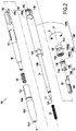
Figure 2 shows an exploded view of the writing instrument offigure 1 , -
Figure 3 shows the shape of the first helical cam, -
Figure 4 shows the shape of the second helical cam, -
Figure 5 shows the developed views of the first and the second helical cam, -
Figure 6 shows a sectional view of the writing instrument offigure 1 , in the plane VI offigure 1 , both the eraser and the writing tip being in the retracted position, -
Figure 7 shows a sectional view of the writing instrument offigure 1 , in the plane VI offigure 1 , the eraser being in the retracted position and the writing tip being in the protruded position, and -
Figure 8 shows a sectional view of the writing instrument offigure 1 , in the plane VIII offigure 6 , both the eraser and the writing tip being in the protruded position. -
Figures 1 and2 show awriting instrument 10 comprising abody 12 extending along an axis X. Thebody 12 has a first end (or front end) 12-1 and a second end (or rear end) 12-2 opposed to the first end 12-1 along the axis X. The first end 12-1 is provided with awriting tip 14 and with aneraser 16. Both thewriting tip 14 and theeraser 16 are movable along the axis X with regard to the body 12 (see double-arrow I infigure 1 ). The writinginstrument 10 comprises a first helical-cam propelling mechanism 18 (seefigure 2 ) configured to move thewriting tip 14 along the axis X between a retracted position (seefigures 1 and6 ) and a protruded position (seefigure 7 ). The writinginstrument 10 comprises a second helical-cam propelling mechanism 20 (seefigure 2 ) configured to move theeraser 16 along the axis X between a retracted position (seefigures 1 and6 ) and a protruded position (seefigure 8 ). - The
body 12 may comprise afirst part 12A and asecond part 12B, thesecond part 12B being rotatable around the axis X with regard to thefirst part 12A and axially coupled with thefirst part 12A. Thesecond part 12B may comprise a first portion 12B1 and a second portion 12B2. The first portion 12B1 may be mounted with thefirst part 12A, the second portion 12B2 being removably coupled with the first portion 12B1. The second portion 12B2 may comprise an outer element 12B22 and an inner element 12B21 disposed at least in part inside the outer element 12B22, the outer element 12B22 being removably coupled with the first portion 12B1, the inner element 12B21 being rotatable with regard to the outer element 12B22 and axially coupled with the outer element 12B22. - The
first part 12A and thesecond part 12B may be assembled by snap fitting, for example via two complementaryannular ribs annular rib 13B. The second portion 12B2 may be removably screwed with the first portion 12B1 via twocomplementary threads thread 13D. The outer element 12B22 and the inner element 12B21 may be assembled by snap fitting, for example via two complementaryannular ribs - When screwed with each other, the first portion 12B1 and the second portion 12B2 may be rotatably and axially coupled. For example, the first portion 12B1 and the second portion 12B2 may be rotatably coupled via complementary axial rib(s) and groove(s) 13G and 13H. The inner element 12B21 may comprise the
ribs 13G. The inner element 12B21 may be rotatably coupled with the first portion 12B1 and the outer element 12B22 may be axially coupled with the inner element 12B21 and at least axially coupled with the first portion 12B1 (e.g. the outer element 12B22 may be also rotatably coupled with the first portion 12B1 depending on the screwing torque). - The
eraser 16 and thewriting tip 14 may be coaxial. Theeraser 16 may be disposed around all or part of the writing tip 14 (e.g. depending of their position). Theeraser 16 may form a sleeve extending along the axis X and configured to receive therein all or part of thewriting tip 14. The writingtip 14 may comprise a writingend 14A. For example, a writing body (or cartridge) 15 may comprise thewriting tip 14 and areservoir 14B configured to feed thewriting tip 14 with ink, for example thermochromic ink. Theeraser 16 may be a friction body. As shown infigure 6 , the writingbody 15 may be integrally located within theeraser 16 when both theeraser 16 and thewriting tip 14 are in the retracted position. When the writinginstrument 10 is seen perpendicular to the axis X as infigures 6 to 8 , the writingend 14A may be concealed by theeraser 16 when theeraser 16 is in the protruded position (seefigure 8 ) and the writingend 14A may free from theeraser 16 when theeraser 16 is in the retracted position and thewriting tip 14 is in the protruded position (seefigure 7 ). - The first helical
cam propelling mechanism 18 comprises afirst cam follower 18A and a firsthelical cam 18B. The second helicalcam propelling mechanism 20 comprises asecond cam follower 20A and a secondhelical cam 20B. As seen infigure 2 , each of thefirst cam follower 18A, the firsthelical cam 18B, thesecond cam follower 20A and the secondhelical cam 20B are provided on a distinct element. For example, thefirst cam follower 18A may be provided on apusher 22, the firsthelical cam 18B may be provided on the inner element 12B21 of the second portion 12B2 of thesecond part 12B of thebody 12, thesecond cam follower 20A may be provided on theeraser 16 and the secondhelical cam 20B may be provided on the first portion 12B1 of thesecond part 12B of thebody 12. - The first
helical cam 18B and the secondhelical cam 20B may be rotatably coupled, for example by rotatably coupling the first portion 12B1 and the second portion 12B2. In the present example, the second part 12B2 may be thus rotatably coupled with the firsthelical cam 18B and the secondhelical cam 20B. In the present example, the first portion 12B1 may thus comprise the secondhelical cam 20B and the second portion 12B2 may thus comprise the firsthelical cam 18B. The inner element 12B21 may thus comprise the firsthelical cam 18B. - The writing
tip 14 may be coupled with the first helicalcam propelling mechanism 18 via thepusher 22. Thepusher 22 may be configured to axially push thewriting tip 14. The writingtip 14 and thepusher 22 may axially bear against each other, and may form together a movable assembly. The first helicalcam propelling mechanism 18 may axially move the writing tip via thepusher 22. Thepusher 22 may extend inside thesecond part 12B. Thepusher 22 and theeraser 16 may be rotatably coupled and axially slidable with regard to each other. For example, thepusher 22 and theeraser 16 may be coupled via complementary axial rib(s) and groove(s) 13K and 13L. Thepusher 22 may be free to rotate with regard to thesecond part 12B. Thepusher 22 may be axially coupled with thesecond part 12B via afirst return spring 23 and the firsthelical cam 18B. In the present example, the firsthelical cam 18B may be configured to push thewriting tip 14 from the retracted position to the protruded position and thefirst return spring 23 may be configured to push thewriting tip 14 from the protruded position to the retracted position. In the present example, thefirst return spring 23 may be a helical compression spring extending axially and having a first distal end bearing against thebody 12 and a second distal end, axially opposite to the first distal end, bearing against the writingtip 14 or the writingbody 15. - By removing the second portion 12B2, in the present example by unscrewing the outer element 12B22 from the first portion 12B1, the inner element 12B21 having the first
helical cam 18B may be removed and free thepusher 22 and thewriting tip 14, in this example the writingbody 15, for refill or replacement. - The
eraser 16 and thefirst part 12A may be rotatably coupled and slidable with regard to each other along the axis X. For example, theeraser 16 and thefirst part 12A may be coupled via complementary axial rib(s) and groove(s) 131 and 13J. Thepusher 22 and thefirst part 12A may be rotatably coupled via theeraser 16. Theeraser 16 may be free to rotate with regard to thesecond part 12B. Theeraser 16 may be axially coupled with thesecond part 12B via asecond return spring 24 and the secondhelical cam 20B. In the present example, the secondhelical cam 20B may be configured to push theeraser 16 from the retracted position to the protruded position and thesecond return spring 24 may be configured to push theeraser 16 from the protruded position to the retracted position. In the present example, thesecond return spring 24 may be a helical compression spring extending axially having a first distal end bearing against thebody 12 and a second distal end, axially opposite to the first distal end, bearing against theeraser 16. - In the present example, the eraser may be not removable when removing the second portion 12B2
- When actuated together, the first helical
cam propelling mechanism 18 and the second helicalcam propelling mechanism 20 may be configured to move thewriting tip 14 from the retracted position to the protruded position first (seefigure 7 ), move theeraser 16 from the retracted position to the protruded position after moving thewriting tip 14 from the retracted position to the protruded position (seefigure 8 ), and then move both thewriting tip 14 and theeraser 16 back to the retracted position (seefigure 6 ). - The first
helical cam 18B and the secondhelical cam 20B may be continuous along the circumferential direction C around the axis X, and may each have an uneven shape. For example, thehelical cams - For example, as shown in
figures 3 and 5 , the firsthelical cam 18B may comprise, one after the other, a firsthelical portion 19A configured to move thewriting tip 14 from the retracted position to the protruded position, adepression 19B configured to provide an indication to the user that thewriting tip 14 is in the protruded position, a secondhelical portion 19C configured to move thewriting tip 14 from the protruded position to an intermediate position between the protruded position and the retracted position, a firstflat portion 19D (perpendicular to the axis X) configured to maintain thewriting tip 14 to the intermediate position, and a secondflat portion 19E (parallel to the axis X), configured to abruptly move thewriting tip 14 from the intermediate position to the retracted position. The firsthelical portion 19A may extend between a starting position corresponding to an angular position of 0° to an angular position of about 180°, thedepression 19B may be disposed at an angular position of about 180°, the secondhelical portion 19C may extend between an angular position of about 180° and an angular position of about 257°, the firstflat portion 19D may extend between an angular position of about 257° and an angular position of about 360° and the secondflat portion 19E may be disposed at about 360°. - For example, as shown in
figures 4 and 5 , the secondhelical cam 20B may comprise, one after the other, a firstflat portion 21A (perpendicular to the axis X) configured to maintain theeraser 16 in the retracted position, a firsthelical portion 21B configured to move theeraser 16 from the retracted position to the protruded position, adepression 21C configured to provide an indication to the user that theeraser 16 is in the protruded position, a secondhelical portion 21D configured to move theeraser 16 from the protruded position to an intermediate position between the protruded position and the retracted position, and a secondflat portion 21E (parallel to the axis X) configured to abruptly move theeraser 16 from the intermediate position to the retracted position. The firstflat portion 21A may extend between a starting position corresponding to an angular position of 0° to an angular position of about 180°, the firsthelical portion 21B may extend between an angular position of about 180° to an angular position of about 345°, thedepression 21C may be disposed at an angular position of about 345°, the secondhelical portion 21D may extend between an angular position of about 345° to an angular position of about 360°, and the secondflat portion 21E may be disposed at about 360°. - The starting point of the first
helical cam 18B may correspond to the same angular positions as a starting point of the secondhelical cam 20B. When both thewriting tip 14 and theeraser 16 are in the retracted position, in the rest position of the writing instrument (i.e. when the first and second helical cam propelling mechanism are not actuated), thefirst cam follower 18A may have the same angular position as the starting point of the firsthelical cam 18B and thesecond cam follower 20A may have the same angular position as the starting point of the secondhelical cam 20B. The angular position of the secondflat portion 19E of the firsthelical cam 18B and of the secondflat portion 21E of the secondhelical cam 20B may be the same. In a variant, the secondflat portion 19E of the firsthelical cam 18B and the secondflat portion 21E of the secondhelical cam 20B may have different angular positions. - The movements of the
writing tip 14 and theeraser 16 of the present example between the retracted position and the protruded position in now explained with reference tofigures 5 to 8 . It is noted that the sectional view shown infigure 8 is perpendicular to the section view shown infigures 6 and7 in order to better show the helicalcam propelling mechanism helical cam 18B and the secondhelical cam 20B being rotatably coupled and belonging to thesecond part 12B, they move together with thesecond part 12B relatively to thefirst part 12A and to the elements rotatably coupled with thefirst part 12A when thesecond part 12B rotates relatively to thefirst part 12A. -
Figure 6 shows the writinginstrument 10 when both thewriting tip 14 and theeraser 16 are in the retracted position. Thefirst cam follower 18A and thesecond cam follower 20A are at the angular position 0° (starting position). In such a position, the secondflat portion 19E of the firsthelical cam 18B and the secondflat portion 21E of the secondhelical cam 20B allow the relative rotation of thesecond part 12B with regard to thefirst part 12A only along the first circumferential direction C1 and block the relative rotation of thesecond part 12B with regard to thefirst part 12A along the second circumferential direction C2, opposite to the first circumferential direction C1. - Arrow A on
figures 3, 4 and 5 represents the relative movements of thefirst cam follower 18A and of thesecond cam follower 20A with regard to the firsthelical cam 18B and to the secondhelical cam 20B, respectively, when thesecond part 12B is rotated with regard to thefirst part 12A in the first circumferential direction C1. When thesecond part 12B is rotated with regard to thefirst part 12A in the second circumferential direction C2, thefirst cam follower 18A and thesecond cam follower 20A move with regard to the firsthelical cam 18B and to the secondhelical cam 20B, respectively, in the direction opposite to arrow A. - When rotating the
second part 12B with regard to thefirst part 12A in the first circumferential direction C1 thefirst cam follower 18A engages with the firsthelical portion 19A of the firsthelical cam 18B, up to engage with thedepression 19B, and thesecond cam follower 20A engages with the firstflat portion 21A. The writingtip 14 is thus moved from the retracted position to the protruded position and theeraser 16 rest in the retracted position. Such a configuration is shown infigure 7 . As seen infigure 5 , the angular position of thedepression 19B of the firsthelical cam 18B may correspond to end of the firstflat portion 21A / beginning of the firsthelical portion 21B of the secondhelical cam 20B. - From the position shown in
figure 7 , thesecond part 12B may be rotated with regard to thefirst part 12A either in the first direction C1 or in the second direction C2. If rotated in the second direction C2, the writingtip 14 is returned in retracted position and theeraser 16 rests in the retracted position, as shown infigure 6 . If rotated in the first rotational direction C1, thefirst cam follower 18A engages first with the secondhelical portion 19C and then with the firstflat portion 19D of the firsthelical cam 18B, and thesecond cam follower 20A engages with the firsthelical portion 21B up to engage with thedepression 21C. The writingtip 14 is thus moved from the protruded position to an intermediate position between the protruded position and the retracted position while theeraser 16 is moved from the retracted position to the protruded position. Such a configuration is shown infigure 8 . As seen infigure 5 , the angular position of thedepression 21C of the secondhelical cam 20B may correspond to an intermediate position in the firstflat portion 19D of the firsthelical cam 18B. - From the position shown in
figure 8 , thesecond part 12B may be rotated with regard to thefirst part 12A either in the first direction C1 or in the second direction C2. If rotated in the second direction C2, the writingtip 14 is returned in protruded position and theeraser 16 is retuned in the retracted position, as shown infigure 7 . If rotated in the first rotational direction C1, thefirst cam follower 18A rests engaged with the firstflat portion 19D up to the secondflat portion 19E and thesecond cam follower 20A engages with the secondhelical portion 21D up to the secondflat portion 21E. Both thewriting tip 14 and the eraser are thus moved to their retracted position, as shown infigure 6 . Thefirst cam follower 18A and thesecond cam follower 20A may thus carry out a complete rotation (along arrow A) and return to the starting position 0° with regard to the firsthelical cam 18B and the secondhelical cam 20B, respectively. Such a complete rotation in the opposite direction may be not allowed, due to the flat 19E, 21E. In a variant, theflats - Although the present disclosure is described with reference to specific examples, it is to be understood that these examples are merely illustrative of the principles and applications of the present disclosure. In particular, individual characteristics of the various embodiments shown and/or mentioned may be combined in additional embodiments. Consequently, the description and the drawings should be considered in a sense that is illustrative rather than restrictive.
- It is intended that the specification and the examples be considered as exemplary only, with a true scope of the invention being indicated by the following claims.
Claims (15)
- A writing instrument (10) comprising a body (12) extending along an axis (X), the body (12) having a first end (12-1) and a second end (12-2) opposed to the first end (12-1) along the axis (X), the first end (12-1) being provided with a writing tip (14) and with an eraser (16), the writing instrument (10) further comprising a first helical cam propelling mechanism (18) configured to move the writing tip (14) along the axis (X) between a retracted position and a protruded position and a second helical cam propelling mechanism (20) configured to move the eraser (16) along the axis (X) between a retracted position and a protruded position, the first helical cam propelling mechanism (18) comprising a first cam follower (18A) and a first helical cam (18B), the second helical cam propelling mechanism (20) comprising a second cam follower (20A) and a second helical cam (20B), each of the first cam follower (18A), the first helical cam (18B), the second cam follower (20A) and the second helical cam (20B) being provided on distinct elements.
- The writing instrument (10) according to claim 1, wherein the eraser (16) and the writing tip (14) are at least in part coaxial, and all or part of the eraser (16) is disposed around all or part of the writing tip (14).
- The writing instrument (10) according to claim 1 or 2, wherein the writing tip (14) comprises a writing end (14A), and, when the writing instrument (10) is seen perpendicular to the axis (X), the writing end (14A) is concealed by the eraser (16) when the eraser (16) is in the protruded position and the writing end (14A) is free from the eraser (16) when the eraser (16) is in the retracted position and the writing tip (14) is in the protruded position.
- The writing instrument (10) according to any one of claims 1 to 3, wherein the first helical cam propelling mechanism (18) and the second helical cam propelling mechanism (20) are configured to, when actuated together, move the writing tip (14) from the retracted position to the protruded position first, move the eraser (16) from the retracted position to the protruded position after moving the writing tip (14) from the retracted position to the protruded position, and then move both the writing tip (14) and the eraser (16) back to the retracted position.
- The writing instrument (10) according to any one of claims 1 to 4, wherein the writing tip (14) is retracted to an intermediate position between the protruded position and the retracted position, when the eraser (16) is moved from the retracted position to the protruded position.
- The writing instrument (10) according to any one of claims 1 to 5, wherein one of the first cam follower (18A) and the first helical cam (18B) and one of the second cam follower (20A) and the second helical cam (20B) are rotatably coupled.
- The writing instrument (10) according to any one of claims 1 to 6, wherein the body (12) comprises a first part (12A) and a second part (12B), the second part (12B) being rotatable around the axis (X) with regard to the first part (12A) and axially coupled with the first part (12A), and the second part (12B) being rotatably coupled with one of the first cam follower (18A) and the first helical cam (18B) and one of the second cam follower (20A) and the second helical cam (20B).
- The writing instrument (10) according to claim 7, wherein the eraser (16) is rotatably coupled with the first part (12A) and axially slidable with regard to the first part (12A).
- The writing instrument (10) according to any one of claims 1 to 8, comprising a pusher (22) configured to push the writing tip (14).
- The writing instrument (10) according to any one of claims 7 to 9, wherein the second part (12B) comprises a first portion (12B1) and a second portion (12B2), the first portion (12B1) is mounted with the first part (12A), the second portion (12B2) being removably coupled with the first portion (12B1).
- The writing instrument according to claim 10, wherein the first portion (12B1) comprises one of the second cam follower (20A) and the second helical cam (20B) and the second portion (12B2) comprises one of the first cam follower (18A) and the first helical cam (18B).
- The writing instrument (10) according to claim 10 or 11, wherein the second portion (12B2) comprises an outer element (12B22) and an inner element (12B21) disposed at least in part inside the outer element (12B22), the outer element (12B22) being removably coupled with the first portion (12B1), the inner element (12B21) being rotatable with regard to the outer element (12B22) and axially coupled with the outer element (12B22).
- The writing instrument (10) according to claims 11 and 12, wherein the inner element (12B21) comprises one of the first cam follower (18A) and the first helical cam (18B).
- The writing instrument (10) according to claim 12 or 13, wherein the inner element (12B21) is rotatably coupled with the first portion (12B1).
- The writing instrument (10) according to any one of claims 1 to 14, comprising a first return spring (23) configured to push the writing tip (14) toward one of the retracted position and the protruded position and/or a second return spring (24) configured to push the eraser (16) toward one of the retracted position and the protruded position.
Priority Applications (3)
| Application Number | Priority Date | Filing Date | Title |
|---|---|---|---|
| EP20306437.3A EP4000946B1 (en) | 2020-11-24 | 2020-11-24 | A writing instrument having a retractable writing tip and a retractable eraser |
| PCT/EP2021/082482 WO2022112164A2 (en) | 2020-11-24 | 2021-11-22 | Writing instruments |
| US18/254,006 US12070968B2 (en) | 2020-11-24 | 2021-11-22 | Writing instruments |
Applications Claiming Priority (1)
| Application Number | Priority Date | Filing Date | Title |
|---|---|---|---|
| EP20306437.3A EP4000946B1 (en) | 2020-11-24 | 2020-11-24 | A writing instrument having a retractable writing tip and a retractable eraser |
Publications (2)
| Publication Number | Publication Date |
|---|---|
| EP4000946A1 true EP4000946A1 (en) | 2022-05-25 |
| EP4000946B1 EP4000946B1 (en) | 2026-01-14 |
Family
ID=73698750
Family Applications (1)
| Application Number | Title | Priority Date | Filing Date |
|---|---|---|---|
| EP20306437.3A Active EP4000946B1 (en) | 2020-11-24 | 2020-11-24 | A writing instrument having a retractable writing tip and a retractable eraser |
Country Status (3)
| Country | Link |
|---|---|
| US (1) | US12070968B2 (en) |
| EP (1) | EP4000946B1 (en) |
| WO (1) | WO2022112164A2 (en) |
Cited By (1)
| Publication number | Priority date | Publication date | Assignee | Title |
|---|---|---|---|---|
| US20220227164A1 (en) * | 2019-04-30 | 2022-07-21 | SOCIéTé BIC | Retractable element for a writing implement |
Citations (1)
| Publication number | Priority date | Publication date | Assignee | Title |
|---|---|---|---|---|
| FR2869834A1 (en) * | 2004-05-04 | 2005-11-11 | Bic Sa Soc | MOBILE GUM WRITING INSTRUMENT |
Family Cites Families (11)
| Publication number | Priority date | Publication date | Assignee | Title |
|---|---|---|---|---|
| DE2912408A1 (en) | 1978-04-01 | 1979-10-04 | Ancos Co Ltd | WRITING DEVICE, IN PARTICULAR MECHANICAL PENCIL |
| US4221490A (en) | 1978-11-30 | 1980-09-09 | The Gillette Company | Two ended retractable writing instrument |
| JPH0753993Y2 (en) | 1989-07-07 | 1995-12-13 | 株式会社パイロット | Cursive appearance mechanism |
| CN2346591Y (en) | 1998-10-05 | 1999-11-03 | 李茂生 | Pen holder for short pencil and eraser |
| CN2426418Y (en) | 1999-12-24 | 2001-04-11 | 宿伟庆 | Environmentally friendly pencil |
| US7066042B2 (en) | 2004-01-07 | 2006-06-27 | Sanford L.P. | Advancing/retracting mechanism |
| US6979142B1 (en) * | 2004-12-06 | 2005-12-27 | Erik Vaclav Chmelar | Retractable tip mechanical pencil assembly |
| CN100469595C (en) | 2005-07-19 | 2009-03-18 | 株式会社百乐 | rotary feed writing instrument |
| JP6312444B2 (en) | 2014-01-17 | 2018-04-18 | 三菱鉛筆株式会社 | Writing instrument with eraser |
| JP2019136947A (en) | 2018-02-11 | 2019-08-22 | 修治 阿部 | Writing instrument capable of erasing letters with tip |
| US11766887B2 (en) * | 2020-08-27 | 2023-09-26 | SOCIéTé BIC | Writing instrument |
-
2020
- 2020-11-24 EP EP20306437.3A patent/EP4000946B1/en active Active
-
2021
- 2021-11-22 US US18/254,006 patent/US12070968B2/en active Active
- 2021-11-22 WO PCT/EP2021/082482 patent/WO2022112164A2/en not_active Ceased
Patent Citations (1)
| Publication number | Priority date | Publication date | Assignee | Title |
|---|---|---|---|---|
| FR2869834A1 (en) * | 2004-05-04 | 2005-11-11 | Bic Sa Soc | MOBILE GUM WRITING INSTRUMENT |
Cited By (2)
| Publication number | Priority date | Publication date | Assignee | Title |
|---|---|---|---|---|
| US20220227164A1 (en) * | 2019-04-30 | 2022-07-21 | SOCIéTé BIC | Retractable element for a writing implement |
| US12122181B2 (en) * | 2019-04-30 | 2024-10-22 | SOCIéTé BIC | Retractable element for a writing implement |
Also Published As
| Publication number | Publication date |
|---|---|
| US20240092116A1 (en) | 2024-03-21 |
| US12070968B2 (en) | 2024-08-27 |
| WO2022112164A3 (en) | 2023-04-27 |
| EP4000946B1 (en) | 2026-01-14 |
| WO2022112164A2 (en) | 2022-06-02 |
Similar Documents
| Publication | Publication Date | Title |
|---|---|---|
| EP1866169B1 (en) | Retractable writing utensil having an airtight valve | |
| US11407248B2 (en) | Retractable nosecone writing instrument | |
| JP7795479B2 (en) | removable writing instrument | |
| CN116507505B (en) | Mechanical pencil | |
| EP4000946B1 (en) | A writing instrument having a retractable writing tip and a retractable eraser | |
| CN111148640B (en) | Multifunctional writing tool | |
| EP3730309A1 (en) | Retractable writing instrument and multi-core writing instrument | |
| JP7628426B2 (en) | Retractable writing implement | |
| US10836205B2 (en) | Manual device with two retractable heads carried by a single carriage | |
| JP2019089272A (en) | Feeding type writing instrument | |
| US10967668B2 (en) | Writing instrument with a locking device | |
| US12122181B2 (en) | Retractable element for a writing implement | |
| US11766886B2 (en) | Writing instrument | |
| US12202294B2 (en) | Writing instruments | |
| JP7607435B2 (en) | Rotational advance mechanism and applicator equipped with rotational advance mechanism | |
| JP6275409B2 (en) | Mounting structure of clip to shaft cylinder | |
| JP7377061B2 (en) | writing implements | |
| US11241905B2 (en) | Manual device with two retractable heads comprising a single mechanism with a single spring | |
| JP2025151152A (en) | removable writing instrument | |
| US20070269252A1 (en) | Write and Correct | |
| WO2014168195A1 (en) | Writing implement |
Legal Events
| Date | Code | Title | Description |
|---|---|---|---|
| PUAI | Public reference made under article 153(3) epc to a published international application that has entered the european phase |
Free format text: ORIGINAL CODE: 0009012 |
|
| STAA | Information on the status of an ep patent application or granted ep patent |
Free format text: STATUS: THE APPLICATION HAS BEEN PUBLISHED |
|
| AK | Designated contracting states |
Kind code of ref document: A1 Designated state(s): AL AT BE BG CH CY CZ DE DK EE ES FI FR GB GR HR HU IE IS IT LI LT LU LV MC MK MT NL NO PL PT RO RS SE SI SK SM TR |
|
| RAP3 | Party data changed (applicant data changed or rights of an application transferred) |
Owner name: SOCIETE BIC |
|
| STAA | Information on the status of an ep patent application or granted ep patent |
Free format text: STATUS: REQUEST FOR EXAMINATION WAS MADE |
|
| 17P | Request for examination filed |
Effective date: 20221124 |
|
| RBV | Designated contracting states (corrected) |
Designated state(s): AL AT BE BG CH CY CZ DE DK EE ES FI FR GB GR HR HU IE IS IT LI LT LU LV MC MK MT NL NO PL PT RO RS SE SI SK SM TR |
|
| GRAP | Despatch of communication of intention to grant a patent |
Free format text: ORIGINAL CODE: EPIDOSNIGR1 |
|
| STAA | Information on the status of an ep patent application or granted ep patent |
Free format text: STATUS: GRANT OF PATENT IS INTENDED |
|
| INTG | Intention to grant announced |
Effective date: 20250901 |
|
| GRAS | Grant fee paid |
Free format text: ORIGINAL CODE: EPIDOSNIGR3 |
|
| GRAA | (expected) grant |
Free format text: ORIGINAL CODE: 0009210 |
|
| STAA | Information on the status of an ep patent application or granted ep patent |
Free format text: STATUS: THE PATENT HAS BEEN GRANTED |
|
| AK | Designated contracting states |
Kind code of ref document: B1 Designated state(s): AL AT BE BG CH CY CZ DE DK EE ES FI FR GB GR HR HU IE IS IT LI LT LU LV MC MK MT NL NO PL PT RO RS SE SI SK SM TR |
|
| REG | Reference to a national code |
Ref country code: CH Ref legal event code: F10 Free format text: ST27 STATUS EVENT CODE: U-0-0-F10-F00 (AS PROVIDED BY THE NATIONAL OFFICE) Effective date: 20260114 Ref country code: GB Ref legal event code: FG4D |
|
| REG | Reference to a national code |
Ref country code: DE Ref legal event code: R096 Ref document number: 602020065452 Country of ref document: DE |
|
| REG | Reference to a national code |
Ref country code: IE Ref legal event code: FG4D |