EP4000766A1 - Method of manufacturing a permanent magnet using a magnetic material mold - Google Patents
Method of manufacturing a permanent magnet using a magnetic material mold Download PDFInfo
- Publication number
- EP4000766A1 EP4000766A1 EP20209447.0A EP20209447A EP4000766A1 EP 4000766 A1 EP4000766 A1 EP 4000766A1 EP 20209447 A EP20209447 A EP 20209447A EP 4000766 A1 EP4000766 A1 EP 4000766A1
- Authority
- EP
- European Patent Office
- Prior art keywords
- magnetic
- mold
- cavity
- magnet
- set forth
- Prior art date
- Legal status (The legal status is an assumption and is not a legal conclusion. Google has not performed a legal analysis and makes no representation as to the accuracy of the status listed.)
- Withdrawn
Links
- 238000004519 manufacturing process Methods 0.000 title claims abstract description 35
- 239000000696 magnetic material Substances 0.000 title claims abstract description 26
- 230000005291 magnetic effect Effects 0.000 claims abstract description 147
- 230000004907 flux Effects 0.000 claims abstract description 61
- 239000006247 magnetic powder Substances 0.000 claims abstract description 38
- 230000035699 permeability Effects 0.000 claims abstract description 35
- 238000000034 method Methods 0.000 claims abstract description 28
- 230000005415 magnetization Effects 0.000 claims abstract description 27
- 238000009826 distribution Methods 0.000 claims abstract description 21
- 239000002245 particle Substances 0.000 claims abstract description 12
- 239000006249 magnetic particle Substances 0.000 claims abstract description 10
- 239000000463 material Substances 0.000 claims description 17
- 238000003825 pressing Methods 0.000 claims description 11
- 239000003302 ferromagnetic material Substances 0.000 claims description 6
- 229910001172 neodymium magnet Inorganic materials 0.000 claims description 6
- 230000008901 benefit Effects 0.000 description 8
- 239000000843 powder Substances 0.000 description 6
- XEEYBQQBJWHFJM-UHFFFAOYSA-N Iron Chemical compound [Fe] XEEYBQQBJWHFJM-UHFFFAOYSA-N 0.000 description 4
- 239000010935 stainless steel Substances 0.000 description 4
- 229910001220 stainless steel Inorganic materials 0.000 description 4
- 230000015572 biosynthetic process Effects 0.000 description 3
- 238000009434 installation Methods 0.000 description 3
- 230000008569 process Effects 0.000 description 3
- 230000008859 change Effects 0.000 description 2
- 229910052742 iron Inorganic materials 0.000 description 2
- 239000000203 mixture Substances 0.000 description 2
- 229910052761 rare earth metal Inorganic materials 0.000 description 2
- 150000002910 rare earth metals Chemical class 0.000 description 2
- 238000005245 sintering Methods 0.000 description 2
- 229910045601 alloy Inorganic materials 0.000 description 1
- 239000000956 alloy Substances 0.000 description 1
- 230000000295 complement effect Effects 0.000 description 1
- 239000008358 core component Substances 0.000 description 1
- 230000001419 dependent effect Effects 0.000 description 1
- 230000000694 effects Effects 0.000 description 1
- 238000004870 electrical engineering Methods 0.000 description 1
- 238000005516 engineering process Methods 0.000 description 1
- 230000005284 excitation Effects 0.000 description 1
- 239000002803 fossil fuel Substances 0.000 description 1
- 230000005381 magnetic domain Effects 0.000 description 1
- 229910052751 metal Inorganic materials 0.000 description 1
- 239000002184 metal Substances 0.000 description 1
- 230000004044 response Effects 0.000 description 1
- 239000000126 substance Substances 0.000 description 1
- 230000007704 transition Effects 0.000 description 1
- 239000013598 vector Substances 0.000 description 1
- 238000004804 winding Methods 0.000 description 1
Images

Classifications
-
- B—PERFORMING OPERATIONS; TRANSPORTING
- B22—CASTING; POWDER METALLURGY
- B22F—WORKING METALLIC POWDER; MANUFACTURE OF ARTICLES FROM METALLIC POWDER; MAKING METALLIC POWDER; APPARATUS OR DEVICES SPECIALLY ADAPTED FOR METALLIC POWDER
- B22F3/00—Manufacture of workpieces or articles from metallic powder characterised by the manner of compacting or sintering; Apparatus specially adapted therefor ; Presses and furnaces
- B22F3/12—Both compacting and sintering
- B22F3/1208—Containers or coating used therefor
-
- H—ELECTRICITY
- H01—ELECTRIC ELEMENTS
- H01F—MAGNETS; INDUCTANCES; TRANSFORMERS; SELECTION OF MATERIALS FOR THEIR MAGNETIC PROPERTIES
- H01F1/00—Magnets or magnetic bodies characterised by the magnetic materials therefor; Selection of materials for their magnetic properties
- H01F1/01—Magnets or magnetic bodies characterised by the magnetic materials therefor; Selection of materials for their magnetic properties of inorganic materials
- H01F1/03—Magnets or magnetic bodies characterised by the magnetic materials therefor; Selection of materials for their magnetic properties of inorganic materials characterised by their coercivity
- H01F1/032—Magnets or magnetic bodies characterised by the magnetic materials therefor; Selection of materials for their magnetic properties of inorganic materials characterised by their coercivity of hard-magnetic materials
- H01F1/04—Magnets or magnetic bodies characterised by the magnetic materials therefor; Selection of materials for their magnetic properties of inorganic materials characterised by their coercivity of hard-magnetic materials metals or alloys
- H01F1/047—Alloys characterised by their composition
- H01F1/053—Alloys characterised by their composition containing rare earth metals
- H01F1/055—Alloys characterised by their composition containing rare earth metals and magnetic transition metals, e.g. SmCo5
- H01F1/057—Alloys characterised by their composition containing rare earth metals and magnetic transition metals, e.g. SmCo5 and IIIa elements, e.g. Nd2Fe14B
- H01F1/0571—Alloys characterised by their composition containing rare earth metals and magnetic transition metals, e.g. SmCo5 and IIIa elements, e.g. Nd2Fe14B in the form of particles, e.g. rapid quenched powders or ribbon flakes
- H01F1/0575—Alloys characterised by their composition containing rare earth metals and magnetic transition metals, e.g. SmCo5 and IIIa elements, e.g. Nd2Fe14B in the form of particles, e.g. rapid quenched powders or ribbon flakes pressed, sintered or bonded together
- H01F1/0577—Alloys characterised by their composition containing rare earth metals and magnetic transition metals, e.g. SmCo5 and IIIa elements, e.g. Nd2Fe14B in the form of particles, e.g. rapid quenched powders or ribbon flakes pressed, sintered or bonded together sintered
-
- H—ELECTRICITY
- H01—ELECTRIC ELEMENTS
- H01F—MAGNETS; INDUCTANCES; TRANSFORMERS; SELECTION OF MATERIALS FOR THEIR MAGNETIC PROPERTIES
- H01F41/00—Apparatus or processes specially adapted for manufacturing or assembling magnets, inductances or transformers; Apparatus or processes specially adapted for manufacturing materials characterised by their magnetic properties
- H01F41/02—Apparatus or processes specially adapted for manufacturing or assembling magnets, inductances or transformers; Apparatus or processes specially adapted for manufacturing materials characterised by their magnetic properties for manufacturing cores, coils, or magnets
- H01F41/0253—Apparatus or processes specially adapted for manufacturing or assembling magnets, inductances or transformers; Apparatus or processes specially adapted for manufacturing materials characterised by their magnetic properties for manufacturing cores, coils, or magnets for manufacturing permanent magnets
- H01F41/0273—Imparting anisotropy
-
- B—PERFORMING OPERATIONS; TRANSPORTING
- B22—CASTING; POWDER METALLURGY
- B22F—WORKING METALLIC POWDER; MANUFACTURE OF ARTICLES FROM METALLIC POWDER; MAKING METALLIC POWDER; APPARATUS OR DEVICES SPECIALLY ADAPTED FOR METALLIC POWDER
- B22F2998/00—Supplementary information concerning processes or compositions relating to powder metallurgy
- B22F2998/10—Processes characterised by the sequence of their steps
-
- B—PERFORMING OPERATIONS; TRANSPORTING
- B22—CASTING; POWDER METALLURGY
- B22F—WORKING METALLIC POWDER; MANUFACTURE OF ARTICLES FROM METALLIC POWDER; MAKING METALLIC POWDER; APPARATUS OR DEVICES SPECIALLY ADAPTED FOR METALLIC POWDER
- B22F2999/00—Aspects linked to processes or compositions used in powder metallurgy
-
- C—CHEMISTRY; METALLURGY
- C22—METALLURGY; FERROUS OR NON-FERROUS ALLOYS; TREATMENT OF ALLOYS OR NON-FERROUS METALS
- C22C—ALLOYS
- C22C2202/00—Physical properties
- C22C2202/02—Magnetic
-
- C—CHEMISTRY; METALLURGY
- C22—METALLURGY; FERROUS OR NON-FERROUS ALLOYS; TREATMENT OF ALLOYS OR NON-FERROUS METALS
- C22C—ALLOYS
- C22C33/00—Making ferrous alloys
- C22C33/02—Making ferrous alloys by powder metallurgy
- C22C33/0257—Making ferrous alloys by powder metallurgy characterised by the range of the alloying elements
- C22C33/0278—Making ferrous alloys by powder metallurgy characterised by the range of the alloying elements with at least one alloying element having a minimum content above 5%
Definitions
- the present invention relates to a method of manufacturing a permanent magnet, in particular a focused magnetic flux magnet. Further, the present invention relates to a method of manufacturing an electromechanical transducer, in particular a generator for a wind turbine. The present invention further relates to a mold and a use of the mold to manufacture a focused magnetic flux magnet.
- the present invention hence relates to the technical field of manufacturing permanent magnets for electromechanical transducers.
- Permanent magnetic materials are used in a plurality of different fields of application. Probably the technically and economically most important field of applications are electromechanical transducers, i.e. electric motors and electric generators.
- An electric motor being equipped with at least one permanent magnet converts electric energy into mechanical energy by producing a temporary varying magnetic field by means of windings or coils. This temporary varying magnetic field interacts with the magnetic field of the PM resulting e.g. in a rotational movement of a rotor arrangement with respect to a stator arrangement of the electric motor.
- an electric generator converts mechanical energy into electric energy.
- An electric generator is a core component of any power plant for generating electric energy. This holds true for power plants which directly capture mechanical energy, e.g. hydroelectric power installations, tidal power installations, and wind power installations also denominated wind turbines. However, this also holds true for power plants which i) first use chemical energy e.g. from burning fossil fuel or from nuclear energy in order to generate thermal energy, and which ii) second convert the generated thermal energy into mechanical energy by means of appropriate thermodynamic processes.
- the efficiency of an electric generator is probably the most important factor for optimizing the production of electric energy.
- a permanent magnet electric generator it is essential that the magnetic flux produced by the permanent magnets is strong, i.e. there is a high level/magnitude of magnetic flux density.
- sintered rare earth magnets e.g. using a NdFeB (Nd 2 Fe 14 B) material composition.
- the spatial magnetic field distribution produced by permanent magnets has an impact on the generator efficiency.
- the performance of torque/power production is determined by an airgap between stator arrangement and rotor arrangement flux density which is produced by the permanent magnets. It has been found that said airgap flux density, and accordingly the torque/power, can be increased, and thereby improved, by utilizing permanent magnets with improved magnetic alignment properties, in particular focused magnetic flux magnets.
- the airgap flux density can be increased by using a higher magnet grade, however there is a physical limitation.
- the magnet can be made thicker, however, this leads to increased magnet volume and hence higher manufacturing costs. Said option also has a physical limitation because, as the magnet thickness is increased, disadvantages with respect to magnetic saturation may occur.
- EP 2762838 A1 describes an apparatus and methods for manufacturing magnets having magnetically oriented grains.
- the field of a permanent magnet is shaped by applying an external field to the material from which the magnet is made in such a way as to magnetize different regions of the material in different directions.
- the apparatus may include a metal-powder press that may press metal powder in the presence of a magnetic field. The press may compress the powder in an axial direction.
- the field may have magnetic flux lines that are transverse to the axial direction.
- the field may have magnetic flux lines that are along the axial direction.
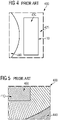
- Figure 4 shows an example of manufacturing a focused magnetic flux permanent magnet according to the prior art: a magnetic powder 430 comprising a plurality of magnetic particles is placed into a cavity 410 of a mold 400.
- the mold 400 is arranged between two magnetic poles 440, wherein the magnetic poles are excited by alignment coils, which provide a magnetic flux 450.
- the region 425 outside the cavity 410 are conventionally made of non-magnetic material with a very low relative magnetic permeability, which is close to the relative magnetic permeability of air, in particular around 1.0 ⁇ r .
- Said non-magnetic material is selected for the required mechanical properties, wherein typically non-magnetic stainless steel is applied.
- the magnetic poles 440 establish the magnetic flux 450 that crosses the cavity 410 to achieve the required alignment of the particles of the magnetic powder 430 inside the cavity 410.
- Figure 5 shows the magnetic flux lines, in other words, the predicted equipotential magnetic field plots, in and around the cavity 410 and also of the magnetic powder 430.
- the cavity 410 is surrounded by a non-magnetic material 425 with a relative magnetic permeability of around 1.0 ⁇ r such as non-magnetic stainless steel.
- Figure 5 shows a zoom to a corner of the cavity 410 of Figure 4 . It can be clearly seen that the magnetic flux lines are distorted and deviate from the desired distribution. Specifically, a change in the declination of the magnetic flux lines can be seen, where the magnetic flux lines cross the boundary between the cavity 410 and the non-magnetic material 425 around the cavity 410.
- a method of manufacturing a permanent magnet in particular a focused magnetic flux magnet
- the method comprising: i) providing a mold, wherein the mold comprises a cavity, in particular having the shape of the magnet to be manufactured, and a mold region, in particular directly, around the cavity, e.g. surrounding the cavity, ii) establishing a magnetic flux, e.g. by using magnetic poles, with respect to the cavity, i.e. in the cavity and at least partially out of the cavity, iii) placing a magnetic powder, comprising a plurality of magnetic particles, e.g.
- the magnetic particles of the magnetic powder are oriented, in particular aligned in the magnet flux to provide an angular distribution of magnetization directions, and iv) forming the permanent magnet from the magnetic powder particles, e.g. by pressing/sintering the magnetic powder particles, with the oriented angular distribution of magnetization directions.
- the mold region comprises a magnetic material, for example a ferromagnetic material like iron, or magnetic stainless steel, with a relative magnetic permeability that is higher than air, in particular 1.01 ⁇ r or higher, more in particular higher than 1.05 ⁇ r , more in particular in the range 1.01 to 10 ⁇ r , more in particular 1.01 to 5 ⁇ r , more in particular 1.03 to 5 ⁇ r .
- a magnetic material for example a ferromagnetic material like iron, or magnetic stainless steel, with a relative magnetic permeability that is higher than air, in particular 1.01 ⁇ r or higher, more in particular higher than 1.05 ⁇ r , more in particular in the range 1.01 to 10 ⁇ r , more in particular 1.01 to 5 ⁇ r , more in particular 1.03 to 5 ⁇ r .
- an electromechanical transducer in particular a generator of a wind turbine, more in particular a direct drive wind turbine, the method comprising: i) providing a stator arrangement, and ii) providing a rotor arrangement using a permanent magnet, in particular a focused magnetic flux magnet manufactured as described above.
- a mold for manufacturing a permanent magnet in particular a focused magnetic flux magnet
- the mold comprises: i) a cavity for receiving a magnetic powder, and ii) a mold region around the cavity, wherein the mold region comprises a material with a relative magnetic permeability ⁇ r that is higher than air, i.e. 1.01 ⁇ r or higher, in particular higher than 1.05 ⁇ r , more in particular in the range 1.01 to 10 ⁇ r , more in particular 1.01 to 5 ⁇ r .
- the term "mold", or mould, cast(ing) mold may in particular refer to any element that comprises a cavity within a mold region, and which element is suitable to form a magnet within said cavity.
- the mold may have any shape or size that is suitable to manufacture the desired magnet. Since magnets are often manufactured by pressing magnetic powder, the mold may be configured to perform/support a powder pressing step.
- the mold may compromise a pressing arm, e.g. a piston, that presses, e.g. punches, the powder inside the cavity, while the magnetic particles are aligned in the magnet field.
- the mold may comprise sidewalls around the cavity. Further, the mold may comprise a pressing part.
- the whole region around the cavity may be made of the magnetic material, or only a part of the mold region may comprise the magnetic material.
- the magnetic powder may be, at least partially, pressed to a compact structure, in particular at least compact enough to not fall apart, wherein the pressing may be sufficient to retain the alignment.
- This compact structure may be taken out of the mold in a further step and may then be further pressed and sintered outside the mold.
- the magnetic permeability is the measure of the resistance of a material against the formation of a magnetic field. Hence, it is the degree of magnetization that a material obtains in response to an applied magnetic field.
- the relative magnetic permeability of air is around 1.0 ⁇ r , while the relative magnetic permeability of, in particular pure, iron is much higher, depending on the grade of purity.
- the magnetic permeability of NdFeB is for example around 1.03 ⁇ r .
- the invention is based on the idea that a method of manufacturing a permanent magnet, in particular a focused magnetic flux magnet, with an improved orientation, in particular alignment, of angular distribution of magnetization directions, can be provided, when the permanent magnet is manufactured using a mold, wherein a mold region around a cavity is made of a magnetic material with a relative magnetic permeability being higher than the relative permeability of air, i.e. 1.01 ⁇ r or higher, in particular 1.03 ⁇ r or higher.
- the described manufacturing method may be applicable to many different permanent magnet shapes, e.g. rectangular, segmented magnets or one-piece magnets, which are manufactured from particles that are aligned, e.g. using magnetic poles, in a magnetic field.
- permanent magnet shapes e.g. rectangular, segmented magnets or one-piece magnets, which are manufactured from particles that are aligned, e.g. using magnetic poles, in a magnetic field.
- the permanent magnet is a focused magnetic flux magnet with an angular, in particular spatial, distribution of magnetization directions resulting in a focused magnetization.
- an electromechanical transducer with especially advantageous power/torque performance can be provided.
- Using a mold material that has a relative magnetic permeability > 1.0 ⁇ r may allow the required magnetic field to be established in the cavity with a lower level of excitation.
- Varying the thickness and/or width and/or shape gives the magnet designer a further degree of freedom for realizing a desired magnetic flux density profile, in particular within in the air gap between the rotor arrangement and the stator arrangement.
- the mold region comprises a ferromagnetic material. This may provide the advantage that an established material with defined magnetic properties can be directly applied. For example, the same material or a material with similar magnetic properties as for the magnetic powder particles may be used.
- the magnetic material of the mold region comprises a magnetic property that is, in particular essentially, equal and/or similar to a magnetic property of the magnetic powder.
- the magnetic material of the mold region comprises a magnetic property that is not less than 0.5 times and not more than 1.5 times in comparison to the magnetic property of the magnetic powder.
- the magnetic saturation of the mold region may be the magnetic saturation of the magnetic powder, in particular ⁇ 0.2 T.
- the magnetic property comprises the magnetic permeability and/or the magnetic saturation.
- Magnetic saturation may be the state reached when an increase in applied external magnetic field cannot increase the magnetization of a material further. Magnetic saturation may be a characteristic of ferromagnetic materials and their alloys.
- the mold region comprises at least one of the group which consists of: the sidewalls, the bottom, the top of the mold.
- the sidewalls and/or the bottom/top may be very thick in order to enlarge the advantage of using the mold region magnetic material.
- At least one diameter of the cavity may be the same or smaller than at least one thickness of the mold region.
- the cavity may further comprise a cover and/or top, and the cover may also be made of the mold region magnetic material.
- the top and/or the bottom may comprise a piston for pressing the magnetic powder in the mold cavity.
- forming comprises: pressing the magnetic powder. This may provide the advantage that known and established magnet formation methods can be directly applied, while the magnetic alignment of the obtained magnet is highly improved.
- the magnetic flux is established by magnetic poles which comprise a ferromagnetic material and/or alignment coils. Also in this case, known and established magnet formation methods can be directly applied, while the magnetic alignment of the obtained magnet is highly improved.
- the magnetic poles are not limited in their shape, e.g. circular as shown in the Figures. Instead, multiple magnetic pole shapes may be realized, for example rectangular, flat, or circular with different radii, or elliptical.
- the method further comprises: forming the focused magnetic flux magnet by one magnet piece.
- the method further comprises: forming the focused magnetic flux magnet by at least two magnet pieces being attached to each other.
- single piece may particularly mean that the respective magnet is integrally or monolithically formed by means of a single bulk magnetic material.
- Using a sintered magnet material, in particular with a rare earth material composition, may provide the advantage that a strong magnetic flux density in particular within the various focal regions can be realized.
- an angular distribution of magnetization directions as described above is based on or is directly related with a preferred direction of particle, e.g. grain, orientations. This means that it is not necessary that all particles, contributing to a particular magnetic domain alignment direction or magnetization line, have to be oriented exactly in the same direction. It is rather only necessary that among a certain distribution of particle orientations there is, in particular in average, a preferred particle orientation.
- the magnetic powder comprises NdFeB, which is a highly effective magnetic material.
- the, in particular focused, magnetization directions of the angular distribution comprise, in particular essentially ideal, straight lines.
- Having focusing magnetization directions along flux lines may provide the advantage that the process of manufacturing the magnet, e.g. during a sintering procedure, may be facilitated. This holds true in particular in view of the matter of fact that an external magnetic field having a corresponding and necessary inhomogeneity can be generated comparatively easy with a proper spatial arrangement of external magnet coils/poles.
- the magnetic focusing of the respective focused magnetic flux magnet may not be perfect.
- the distribution of magnetization directions may result, at least in a cross-sectional view, in a focal volume having a certain spatial extension.
- the magnetic focal region may be, at least in a cross-sectional view, a magnetic focal point.
- the described focusing may be i) a two dimensional (2D) focusing or ii) a three dimensional (3D) focusing.
- the wind turbine is a direct drive wind turbine.
- a generator comprises a stator arrangement and a rotor arrangement.
- the generator is realized in a so called “inner stator - outer rotor" configuration, wherein the rotor arrangement surrounds the stator arrangement. This means that permanent magnets are moved around an arrangement of a plurality of coils of the inner stator arrangement which coils produce an induced current resulting from picking up a time varying magnetic flux from the moving permanent magnets.
- spatially relative terms such as “front” and “back”, “above” and “below”, “left” and “right”, et cetera are used to describe an element's relationship to another element(s) as illustrated in the figures.
- the spatially relative terms may apply to orientations in use which differ from the orientation depicted in the figures.
- All such spatially relative terms refer to the orientation shown in the figures only for ease of description and are not necessarily limiting as an apparatus according to an embodiment of the invention can assume orientations different than those illustrated in the figures when in use.
- a magnetic material is used outside the cavity of the mold.
- This magnetic material should have a permeability higher than the air and there are not particular upper limits for this permeability, depending on the specific mold design and dimensions.
- the magnetic saturation and/or the relative magnetic permeability of this material is preferentially similar to that of the magnetic powder, but there are also no specific limits for the magnetic saturation of this materials.
- Figure 1 shows a mold 100 for manufacturing a permanent magnet, wherein the mold 100 comprises a cavity 110 for receiving a magnetic powder 130 that comprises magnetic particles.
- the mold 100 further comprises a mold region 120 arranged around the cavity 110, wherein the mold region 120 comprises the sidewalls and the bottom of the cavity 110.
- the mold region 120 is very thick in comparison to the size of the cavity 110.
- the mold region 120 comprises a material with a relative magnetic permeability that is larger than the relative magnetic permeability of air, larger than the relative magnetic permeability of non-magnetic stainless steel, and larger than 1.01 ⁇ r .
- the non-magnetic material of the prior art is replaced with a magnetic material having magnetic properties (essentially) similar to the magnetic powder 130 within the cavity.
- the magnetic powder 130 When performing the described manufacturing method, the magnetic powder 130 is placed into a cavity 110 of the mold 100.
- the magnetic flux 150 is established using, e.g. at least two, magnetic poles 140 arranged with respect to the cavity 110.
- the magnetic particles of the magnetic powder 130 are then oriented in the magnet flux 150 to provide an angular distribution of magnetization directions.
- the permanent magnet is formed from the magnetic powder 130 with oriented angular distribution of magnetization directions by pressing the particles within the cavity 110. In case that a focused magnetic flux magnet is formed, the angular distribution of magnetization directions is focused.
- Figure 2 shows the magnetic flux lines 150 during the manufacturing process.
- the cavity 110 is surrounded by a mold region 120 magnetic material with a relative magnetic permeability of more than 1.01 ⁇ r , in particular similar to that of the magnetic powder 130.
- a relative magnetic permeability of more than 1.01 ⁇ r in particular similar to that of the magnetic powder 130.
- Figure 3 shows a zoom to a corner of the cavity 110 of Figure 2 , i.e. an interface between the cavity 110 and the mold region 120. It can be clearly seen that the magnetic flux lines 150 are not distorted and do not deviate from the desired distribution. No change in the declination of the magnetic flux lines 150 can be seen, where the magnetic flux lines 150 cross the interface between cavity 110 and mold region 120.
Landscapes
- Engineering & Computer Science (AREA)
- Power Engineering (AREA)
- Manufacturing & Machinery (AREA)
- Mechanical Engineering (AREA)
- Chemical & Material Sciences (AREA)
- Crystallography & Structural Chemistry (AREA)
- Inorganic Chemistry (AREA)
- Powder Metallurgy (AREA)
- Manufacturing Cores, Coils, And Magnets (AREA)
Abstract
It is described a method of manufacturing a permanent magnet, the method comprising: i) providing a mold (100), wherein the mold (100) comprises a cavity (110), and a mold region (120) around the cavity (110), ii) establishing a magnetic flux (150) with respect to the cavity (110), iii) placing a magnetic powder (130), comprising a plurality of magnetic particles, into the cavity (110), so that the magnetic particles of the magnetic powder (130) are oriented in the magnet flux (150) to provide an angular distribution of magnetization directions, and iv) forming the permanent magnet from the magnetic powder (130) particles with the oriented angular distribution of magnetization directions. The mold region (120) comprises a magnetic material with a relative magnetic permeability that is larger than the relative magnetic permeability of air, in particular larger than 1.01 µ<sub>r</sub>. Further, a method of providing an electromechanical transducer, a mold (100), and a use of the mold (100) are described.
Description
- The present invention relates to a method of manufacturing a permanent magnet, in particular a focused magnetic flux magnet. Further, the present invention relates to a method of manufacturing an electromechanical transducer, in particular a generator for a wind turbine. The present invention further relates to a mold and a use of the mold to manufacture a focused magnetic flux magnet.
- The present invention hence relates to the technical field of manufacturing permanent magnets for electromechanical transducers.
- Permanent magnetic materials are used in a plurality of different fields of application. Probably the technically and economically most important field of applications are electromechanical transducers, i.e. electric motors and electric generators. An electric motor being equipped with at least one permanent magnet converts electric energy into mechanical energy by producing a temporary varying magnetic field by means of windings or coils. This temporary varying magnetic field interacts with the magnetic field of the PM resulting e.g. in a rotational movement of a rotor arrangement with respect to a stator arrangement of the electric motor. In a physically complementary manner, an electric generator converts mechanical energy into electric energy.
- An electric generator is a core component of any power plant for generating electric energy. This holds true for power plants which directly capture mechanical energy, e.g. hydroelectric power installations, tidal power installations, and wind power installations also denominated wind turbines. However, this also holds true for power plants which i) first use chemical energy e.g. from burning fossil fuel or from nuclear energy in order to generate thermal energy, and which ii) second convert the generated thermal energy into mechanical energy by means of appropriate thermodynamic processes.
- The efficiency of an electric generator is probably the most important factor for optimizing the production of electric energy. For a permanent magnet electric generator, it is essential that the magnetic flux produced by the permanent magnets is strong, i.e. there is a high level/magnitude of magnetic flux density. Presently, this can probably best be achieved with sintered rare earth magnets, e.g. using a NdFeB (Nd2Fe14B) material composition. However, also the spatial magnetic field distribution produced by permanent magnets has an impact on the generator efficiency.
- In permanent magnet comprising electromechanical transducers, for example generators for direct-drive wind turbines, the performance of torque/power production is determined by an airgap between stator arrangement and rotor arrangement flux density which is produced by the permanent magnets. It has been found that said airgap flux density, and accordingly the torque/power, can be increased, and thereby improved, by utilizing permanent magnets with improved magnetic alignment properties, in particular focused magnetic flux magnets.
- Conventionally, the airgap flux density can be increased by using a higher magnet grade, however there is a physical limitation. Alternatively, the magnet can be made thicker, however, this leads to increased magnet volume and hence higher manufacturing costs. Said option also has a physical limitation because, as the magnet thickness is increased, disadvantages with respect to magnetic saturation may occur.
-
EP 2762838 A1 describes an apparatus and methods for manufacturing magnets having magnetically oriented grains. The field of a permanent magnet is shaped by applying an external field to the material from which the magnet is made in such a way as to magnetize different regions of the material in different directions. The apparatus may include a metal-powder press that may press metal powder in the presence of a magnetic field. The press may compress the powder in an axial direction. The field may have magnetic flux lines that are transverse to the axial direction. The field may have magnetic flux lines that are along the axial direction. -
Figure 4 shows an example of manufacturing a focused magnetic flux permanent magnet according to the prior art: amagnetic powder 430 comprising a plurality of magnetic particles is placed into acavity 410 of amold 400. Hereby, themold 400 is arranged between twomagnetic poles 440, wherein the magnetic poles are excited by alignment coils, which provide amagnetic flux 450. Theregion 425 outside thecavity 410 are conventionally made of non-magnetic material with a very low relative magnetic permeability, which is close to the relative magnetic permeability of air, in particular around 1.0 µr. Said non-magnetic material is selected for the required mechanical properties, wherein typically non-magnetic stainless steel is applied. Themagnetic poles 440 establish themagnetic flux 450 that crosses thecavity 410 to achieve the required alignment of the particles of themagnetic powder 430 inside thecavity 410. - However, the conventional manufacturing method of permanent magnets has disadvantages which is illustrated in
Figure 5 below, wherein theprior art mold 400 is shown in detail. -
Figure 5 shows the magnetic flux lines, in other words, the predicted equipotential magnetic field plots, in and around thecavity 410 and also of themagnetic powder 430. Hereby, thecavity 410 is surrounded by anon-magnetic material 425 with a relative magnetic permeability of around 1.0 µr such as non-magnetic stainless steel. In particular,Figure 5 shows a zoom to a corner of thecavity 410 ofFigure 4 . It can be clearly seen that the magnetic flux lines are distorted and deviate from the desired distribution. Specifically, a change in the declination of the magnetic flux lines can be seen, where the magnetic flux lines cross the boundary between thecavity 410 and thenon-magnetic material 425 around thecavity 410. - There may be a need for providing a method of manufacturing a permanent magnet, in particular a focused magnetic flux magnet, with an improved orientation of angular distribution of magnetization directions.
- This need may be met by the subject matter according to the independent claims. Advantageous embodiments of the present invention are described by the dependent claims.
- According to a first aspect of the invention, there is described a method of manufacturing a permanent magnet, in particular a focused magnetic flux magnet, the method comprising: i) providing a mold, wherein the mold comprises a cavity, in particular having the shape of the magnet to be manufactured, and a mold region, in particular directly, around the cavity, e.g. surrounding the cavity, ii) establishing a magnetic flux, e.g. by using magnetic poles, with respect to the cavity, i.e. in the cavity and at least partially out of the cavity, iii) placing a magnetic powder, comprising a plurality of magnetic particles, e.g. made of NdFeB, into the cavity, so that the magnetic particles of the magnetic powder are oriented, in particular aligned in the magnet flux to provide an angular distribution of magnetization directions, and iv) forming the permanent magnet from the magnetic powder particles, e.g. by pressing/sintering the magnetic powder particles, with the oriented angular distribution of magnetization directions. The mold region comprises a magnetic material, for example a ferromagnetic material like iron, or magnetic stainless steel, with a relative magnetic permeability that is higher than air, in particular 1.01 µr or higher, more in particular higher than 1.05 µr, more in particular in the range 1.01 to 10 µr, more in particular 1.01 to 5 µr, more in particular 1.03 to 5 µr.
- According to a further aspect of the invention, there is provided a method of manufacturing an electromechanical transducer, in particular a generator of a wind turbine, more in particular a direct drive wind turbine, the method comprising: i) providing a stator arrangement, and ii) providing a rotor arrangement using a permanent magnet, in particular a focused magnetic flux magnet manufactured as described above.
- According to a further aspect of the invention, there is described a mold for manufacturing a permanent magnet, in particular a focused magnetic flux magnet, wherein the mold comprises: i) a cavity for receiving a magnetic powder, and ii) a mold region around the cavity, wherein the mold region comprises a material with a relative magnetic permeability µr that is higher than air, i.e. 1.01 µr or higher, in particular higher than 1.05 µr, more in particular in the range 1.01 to 10 µr, more in particular 1.01 to 5 µr.
- According to a further aspect of the invention, there is described, a method of, using the mold as discussed above for manufacturing a focused magnetic flux magnet.
- In the context of the present document, the term "mold", or mould, cast(ing) mold, may in particular refer to any element that comprises a cavity within a mold region, and which element is suitable to form a magnet within said cavity. The mold may have any shape or size that is suitable to manufacture the desired magnet. Since magnets are often manufactured by pressing magnetic powder, the mold may be configured to perform/support a powder pressing step. For example, the mold may compromise a pressing arm, e.g. a piston, that presses, e.g. punches, the powder inside the cavity, while the magnetic particles are aligned in the magnet field. The mold may comprise sidewalls around the cavity. Further, the mold may comprise a pressing part. The whole region around the cavity may be made of the magnetic material, or only a part of the mold region may comprise the magnetic material. The magnetic powder may be, at least partially, pressed to a compact structure, in particular at least compact enough to not fall apart, wherein the pressing may be sufficient to retain the alignment. This compact structure may be taken out of the mold in a further step and may then be further pressed and sintered outside the mold.
- In the context of the present document, the term "magnetic permeability" may in particular refer to the ratio of the magnetic permeability of a specific medium µ to the magnetic permeability of free space µ0, in particular the amount of resistance encountered when forming a magnetic field in a classical vacuum, being a physical constant, i.e. µr = µ/µ0. The magnetic permeability is the measure of the resistance of a material against the formation of a magnetic field. Hence, it is the degree of magnetization that a material obtains in response to an applied magnetic field. The relative magnetic permeability of air is around 1.0 µr, while the relative magnetic permeability of, in particular pure, iron is much higher, depending on the grade of purity. The magnetic permeability of NdFeB is for example around 1.03 µr.
- According to an exemplary embodiment, the invention is based on the idea that a method of manufacturing a permanent magnet, in particular a focused magnetic flux magnet, with an improved orientation, in particular alignment, of angular distribution of magnetization directions, can be provided, when the permanent magnet is manufactured using a mold, wherein a mold region around a cavity is made of a magnetic material with a relative magnetic permeability being higher than the relative permeability of air, i.e. 1.01 µr or higher, in particular 1.03 µr or higher.
- It has been surprisingly found by the inventors that large misalignments of the magnetic flux pattern in the prior art (see
Figures 5 and 6 above) are caused by leakage effects, especially at the interface between mold cavity and mold region, during the manufacturing process due to changes in the magnetic permeability within the magnetic flux path, as it passes from the non-magnetic mold region into the mold cavity with the magnetic powder. Thereby, a non-linear magnetic permeability and/or non-linear magnetic saturation occurs. In other words, undesired local deviations in the field may occur due to the transition from a permeability into the cavity region with a non-linear permeability > 1 in the cavity. This may cause the alignment field to be distorted from the desired pattern. - The inventors have further found that these disadvantages may be overcome in an efficient, robust, and easy manner, when the mold region around the cavity is made of a magnetic material with a high magnetic permeability/saturation, in particular with magnetic properties that are very close to the magnetic properties of the applied magnetic powder. In this manner, permanent magnets, in particular focused magnetic flux magnets, can be manufactured with improved magnetic alignment properties and less leakage, i.e. distortion of the desired field. When applying the described improved permanent magnets, also the torque/power performance of an electromechanical transducer, e.g. a wind turbine, can be increased.
- The described manufacturing method may be applicable to many different permanent magnet shapes, e.g. rectangular, segmented magnets or one-piece magnets, which are manufactured from particles that are aligned, e.g. using magnetic poles, in a magnetic field.
- According to an embodiment, the permanent magnet is a focused magnetic flux magnet with an angular, in particular spatial, distribution of magnetization directions resulting in a focused magnetization. In this manner, an electromechanical transducer with especially advantageous power/torque performance can be provided.
- So far, focused magnetic flux magnets have not been implemented in large power applications such as wind turbine generators, in particular direct-drive wind turbines. An approach to overcome the issues of the focused magnetic flux magnet manufacturing (as outlined above) may be achieved by the described manufacturing method.
- Using a mold material that has a relative magnetic permeability > 1.0 µr may allow the required magnetic field to be established in the cavity with a lower level of excitation.
- Varying the thickness and/or width and/or shape gives the magnet designer a further degree of freedom for realizing a desired magnetic flux density profile, in particular within in the air gap between the rotor arrangement and the stator arrangement.
- According to a further embodiment, the mold region comprises a ferromagnetic material. This may provide the advantage that an established material with defined magnetic properties can be directly applied. For example, the same material or a material with similar magnetic properties as for the magnetic powder particles may be used.
- According to a further embodiment, the magnetic material of the mold region comprises a magnetic property that is, in particular essentially, equal and/or similar to a magnetic property of the magnetic powder. In particular, the magnetic material of the mold region comprises a magnetic property that is not less than 0.5 times and not more than 1.5 times in comparison to the magnetic property of the magnetic powder. In this manner, at an interface between cavity/magnetic powder and mold region, misalignment and leakage in the magnetic flux may be, in particular completely, suppressed.
- According to an exemplary example, the magnetic saturation of the mold region may be the magnetic saturation of the magnetic powder, in particular ± 0.2 T.
- According to a further embodiment, the magnetic property comprises the magnetic permeability and/or the magnetic saturation. By providing, in particular essentially, the same magnetic saturation, or a similar magnetic saturation, the magnetic flux alignment is improved.
- In the context of this document, the term "magnetic saturation" may be the state reached when an increase in applied external magnetic field cannot increase the magnetization of a material further. Magnetic saturation may be a characteristic of ferromagnetic materials and their alloys.
- According to a further embodiment, the mold region comprises at least one of the group which consists of: the sidewalls, the bottom, the top of the mold. Hereby, the sidewalls and/or the bottom/top may be very thick in order to enlarge the advantage of using the mold region magnetic material. At least one diameter of the cavity may be the same or smaller than at least one thickness of the mold region. The cavity may further comprise a cover and/or top, and the cover may also be made of the mold region magnetic material. The top and/or the bottom may comprise a piston for pressing the magnetic powder in the mold cavity.
- According to a further embodiment, forming comprises: pressing the magnetic powder. This may provide the advantage that known and established magnet formation methods can be directly applied, while the magnetic alignment of the obtained magnet is highly improved.
- According to a further embodiment, the magnetic flux is established by magnetic poles which comprise a ferromagnetic material and/or alignment coils. Also in this case, known and established magnet formation methods can be directly applied, while the magnetic alignment of the obtained magnet is highly improved.
- According to an embodiment, the magnetic poles are not limited in their shape, e.g. circular as shown in the Figures. Instead, multiple magnetic pole shapes may be realized, for example rectangular, flat, or circular with different radii, or elliptical.
- According to a further embodiment, the method further comprises: forming the focused magnetic flux magnet by one magnet piece.
- According to a further embodiment, the method further comprises: forming the focused magnetic flux magnet by at least two magnet pieces being attached to each other.
- This may provide the advantage that the, in particular focused, magnet can be realized by composing or assembling smaller magnet pieces. Although assembling the different magnet pieces may require some additional effort, this additional effort will, in most cases, be overcompensated because only smaller magnet pieces have to be produced. This holds true because in order to realize a focused magnetic flux magnet, it is sometimes easier to manufacture two or more small focusing magnet pieces than to manufacture one larger focusing magnet piece.
- It is mentioned that of course at least one magnet can be realized with a single magnet piece. In the context of this document, the term "single piece" may particularly mean that the respective magnet is integrally or monolithically formed by means of a single bulk magnetic material.
- Using a sintered magnet material, in particular with a rare earth material composition, may provide the advantage that a strong magnetic flux density in particular within the various focal regions can be realized.
- In order to avoid any misunderstanding with regard to the internal magnetization structure of the sintered magnet it is pointed out that an angular distribution of magnetization directions as described above is based on or is directly related with a preferred direction of particle, e.g. grain, orientations. This means that it is not necessary that all particles, contributing to a particular magnetic domain alignment direction or magnetization line, have to be oriented exactly in the same direction. It is rather only necessary that among a certain distribution of particle orientations there is, in particular in average, a preferred particle orientation.
- According to a further embodiment, the magnetic powder comprises NdFeB, which is a highly effective magnetic material.
- According to a further embodiment, the, in particular focused, magnetization directions of the angular distribution comprise, in particular essentially ideal, straight lines.
- Having focusing magnetization directions along flux lines may provide the advantage that the process of manufacturing the magnet, e.g. during a sintering procedure, may be facilitated. This holds true in particular in view of the matter of fact that an external magnetic field having a corresponding and necessary inhomogeneity can be generated comparatively easy with a proper spatial arrangement of external magnet coils/poles.
- It is pointed out that the magnetic focusing of the respective focused magnetic flux magnet may not be perfect. Hence, the distribution of magnetization directions may result, at least in a cross-sectional view, in a focal volume having a certain spatial extension. In case of a perfect focusing the magnetic focal region may be, at least in a cross-sectional view, a magnetic focal point.
- In this regard it is further mentioned that the described focusing may be i) a two dimensional (2D) focusing or ii) a three dimensional (3D) focusing.
- i) In case of a 2D focusing the magnetization directions are distributed two-dimensionally. This means that all magnetization vectors are oriented within or parallel to a plane being defined by an x-axis and a z-axis. Thereby, the z-axis may be associated with a thickness direction of the magnet portion and the x-axis, which is perpendicular to this z-axis, may be associated with a width direction of respective magnet portion. In the "real 3D world" a theoretically perfect focusing would result in a focal line. In the field of optics, a 2D focusing is achieved e.g. by means of a cylindrical lens.
- ii) In case of a 3D focusing the magnetization directions are distributed three-dimensionally. This means that there is not only a focusing along one direction, e.g. the above mentioned x-direction, but also along another direction being perpendicular thereto. Specifically, this another direction may be parallel to a y-axis which is perpendicular to both the x-axis and the above mentioned z-axis. The y-axis may define a depth direction of the respective magnetic portion. In the "real 3D world" a theoretically perfect 3D focusing would result in a focal point.
- According to an embodiment, the wind turbine is a direct drive wind turbine. This may provide the advantage that the described technology can be directly implemented into a highly efficient wind turbine, thereby further improving the energy yield. In accordance with basic principles of electrical engineering, a generator comprises a stator arrangement and a rotor arrangement. In the case of a direct drive wind turbine, the generator is realized in a so called "inner stator - outer rotor" configuration, wherein the rotor arrangement surrounds the stator arrangement. This means that permanent magnets are moved around an arrangement of a plurality of coils of the inner stator arrangement which coils produce an induced current resulting from picking up a time varying magnetic flux from the moving permanent magnets.
- The aspects defined above and further aspects of the present invention are apparent from the examples of embodiment to be described hereinafter and are explained with reference to the examples of embodiment. The invention will be described in more detail hereinafter with reference to examples of embodiment but to which the invention is not limited.
-
- Figure 1
- shows a mold according to an exemplary embodiment of the invention.
- Figures 2 and 3
- show the mold according to an exemplary embodiment of the invention in detail.
- Figure 4
- shows a mold from the prior art.
- Figure 5
- show the mold from the prior art in detail.
- The illustration in the drawing is schematic. It is noted that in different figures, similar or identical elements or features are provided with the same reference signs or with reference signs, which are different from the corresponding reference signs only within the first digit. In order to avoid unnecessary repetitions elements or features which have already been elucidated with respect to a previously described embodiment are not elucidated again at a later position of the description.
- Further, spatially relative terms, such as "front" and "back", "above" and "below", "left" and "right", et cetera are used to describe an element's relationship to another element(s) as illustrated in the figures. Thus, the spatially relative terms may apply to orientations in use which differ from the orientation depicted in the figures. Obviously all such spatially relative terms refer to the orientation shown in the figures only for ease of description and are not necessarily limiting as an apparatus according to an embodiment of the invention can assume orientations different than those illustrated in the figures when in use.
- Before referring to the drawings in detail, exemplary embodiments of the invention are described in detail in the following.
- According to an exemplary embodiment, in order to improve the alignment of the magnetic fields, it is proposed that a magnetic material is used outside the cavity of the mold. This magnetic material should have a permeability higher than the air and there are not particular upper limits for this permeability, depending on the specific mold design and dimensions. The magnetic saturation and/or the relative magnetic permeability of this material is preferentially similar to that of the magnetic powder, but there are also no specific limits for the magnetic saturation of this materials. Using the proposed solution, better alignment and less leakage can be achieved inside the cavity during the alignment process of the powder.
- According to an exemplary embodiment, the following advantages may be provided:
- i) enable and maximize the implementation of focused magnetic flux magnets and allow alignment patterns closer to the theoretical ideal requirements,
- ii) enhance the capability of machines, power, torque, and Annual Energy Production (AEP) by allowing optimum focused magnetic flux angles to be achieved in the magnet,
- iii) improve the circumferential alignment of the magnet and offer better performance for generators,
- iv) enable manufacturing of larger focused magnetic flux magnets.
-
Figure 1 shows amold 100 for manufacturing a permanent magnet, wherein themold 100 comprises acavity 110 for receiving amagnetic powder 130 that comprises magnetic particles. Themold 100 further comprises amold region 120 arranged around thecavity 110, wherein themold region 120 comprises the sidewalls and the bottom of thecavity 110. As can be seen, themold region 120 is very thick in comparison to the size of thecavity 110. Themold region 120 comprises a material with a relative magnetic permeability that is larger than the relative magnetic permeability of air, larger than the relative magnetic permeability of non-magnetic stainless steel, and larger than 1.01 µr. Thus, the non-magnetic material of the prior art is replaced with a magnetic material having magnetic properties (essentially) similar to themagnetic powder 130 within the cavity. - When performing the described manufacturing method, the
magnetic powder 130 is placed into acavity 110 of themold 100. Themagnetic flux 150 is established using, e.g. at least two,magnetic poles 140 arranged with respect to thecavity 110. The magnetic particles of themagnetic powder 130 are then oriented in themagnet flux 150 to provide an angular distribution of magnetization directions. The permanent magnet is formed from themagnetic powder 130 with oriented angular distribution of magnetization directions by pressing the particles within thecavity 110. In case that a focused magnetic flux magnet is formed, the angular distribution of magnetization directions is focused. -
Figure 2 shows themagnetic flux lines 150 during the manufacturing process. Thecavity 110 is surrounded by amold region 120 magnetic material with a relative magnetic permeability of more than 1.01 µr, in particular similar to that of themagnetic powder 130. In comparison to the prior art example ofFigure 5 , there is less distortion/deviation of themagnetic flux lines 150 visible. -
Figure 3 shows a zoom to a corner of thecavity 110 ofFigure 2 , i.e. an interface between thecavity 110 and themold region 120. It can be clearly seen that themagnetic flux lines 150 are not distorted and do not deviate from the desired distribution. No change in the declination of themagnetic flux lines 150 can be seen, where themagnetic flux lines 150 cross the interface betweencavity 110 andmold region 120. - It should be noted that the term "comprising" does not exclude other elements or steps and the use of articles "a" or "an" does not exclude a plurality. Also elements described in association with different embodiments may be combined. It should also be noted that reference signs in the claims should not be construed as limiting the scope of the claims.
Claims (15)
- A method of manufacturing a permanent magnet, the method comprising:providing a mold (100), wherein the mold (100) comprises a cavity (110), and a mold region (120) around the cavity (110) ;establishing a magnetic flux (150) with respect to the cavity (110);placing a magnetic powder (130), comprising a plurality of magnetic particles, into the cavity (110), so that the magnetic particles of the magnetic powder (130) are oriented in the magnet flux (150) to provide an angular distribution of magnetization directions; andforming the permanent magnet from the magnetic powder (130) particles with the oriented angular distribution of magnetization directions;wherein the mold region (120) comprises a magnetic material with a relative magnetic permeability that is larger than the relative magnetic permeability of air, in particular larger than 1.01 µr.
- The method as set forth in claim 1,
wherein the permanent magnet is a focused magnetic flux magnet with an angular distribution of magnetization directions resulting in a focused magnetization. - The method as set forth in claim 1 or 2,
wherein the mold region (120) comprises a ferromagnetic material. - The method as set forth in any one of the preceding claims,
wherein the magnetic material of the mold region (120) comprises a magnetic property that is essentially equal to a magnetic property of the magnetic powder (130),
in particular, the magnetic material of the mold region (120) comprises a magnetic property that is not less than 0.5 times and not more than 1.5 times in comparison to the magnetic property of the magnetic powder (130). - The method as set forth in claim 4,
wherein the magnetic property comprises the magnetic saturation or the relative magnetic permeability. - The method as set forth in any one of the preceding claims 1 to 5,
wherein the mold region (120) comprises at least one of the sidewalls, the bottom, the top of the mold (100). - The method as set forth in any one of the preceding claims, wherein forming comprises:
pressing the magnetic powder (130) in the mold (120), in particular using a pressing part of the mold (120). - The method as set forth in any one of the preceding claims 1 to 7,
wherein the magnetic flux (150) is established by magnetic poles (140) which comprise a ferromagnetic material and/or alignment coils. - The method as set forth in any one of the claims 2 to 8, wherein the method further comprises:
forming the focused magnetic flux magnet by at least two magnet pieces being attached to each other. - The method as set forth in any one of the preceding claims,
wherein the magnetic powder (130) comprises NdFeB. - The method as set forth in any one of the preceding claims,
wherein the magnetization directions of the angular distribution comprise ideal straight lines. - A method of manufacturing an electromechanical transducer, in particular a generator of a wind turbine, the method comprising:providing a stator arrangement; andproviding a rotor arrangement using a permanent magnet manufactured as set forth in any one of the claims 1 to 11.
- The method according to claim 12, wherein the wind turbine is a direct drive wind turbine.
- A mold (100) for manufacturing a permanent magnet, wherein the mold (100) comprises:a cavity (110) for receiving a magnetic powder (130); anda mold region (120) around the cavity (110);wherein the mold region (120) comprises a material with a relative magnetic permeability that is larger than the relative magnetic permeability of air, in particular larger than 1.01 µr.
- Using the mold (100) according to claim 14 for manufacturing a focused magnetic flux magnet.
Priority Applications (3)
| Application Number | Priority Date | Filing Date | Title |
|---|---|---|---|
| EP20209447.0A EP4000766A1 (en) | 2020-11-24 | 2020-11-24 | Method of manufacturing a permanent magnet using a magnetic material mold |
| CN202180079104.4A CN116490938A (en) | 2020-11-24 | 2021-09-17 | Method for manufacturing permanent magnet using magnetic material mold |
| PCT/EP2021/075617 WO2022111876A1 (en) | 2020-11-24 | 2021-09-17 | Method of manufacturing a permanent magnet using a magnetic material mold |
Applications Claiming Priority (1)
| Application Number | Priority Date | Filing Date | Title |
|---|---|---|---|
| EP20209447.0A EP4000766A1 (en) | 2020-11-24 | 2020-11-24 | Method of manufacturing a permanent magnet using a magnetic material mold |
Publications (1)
| Publication Number | Publication Date |
|---|---|
| EP4000766A1 true EP4000766A1 (en) | 2022-05-25 |
Family
ID=73554298
Family Applications (1)
| Application Number | Title | Priority Date | Filing Date |
|---|---|---|---|
| EP20209447.0A Withdrawn EP4000766A1 (en) | 2020-11-24 | 2020-11-24 | Method of manufacturing a permanent magnet using a magnetic material mold |
Country Status (3)
| Country | Link |
|---|---|
| EP (1) | EP4000766A1 (en) |
| CN (1) | CN116490938A (en) |
| WO (1) | WO2022111876A1 (en) |
Families Citing this family (1)
| Publication number | Priority date | Publication date | Assignee | Title |
|---|---|---|---|---|
| JP2025062435A (en) * | 2023-10-02 | 2025-04-14 | トヨタ自動車株式会社 | Manufacturing method of rare earth magnet |
Citations (5)
| Publication number | Priority date | Publication date | Assignee | Title |
|---|---|---|---|---|
| WO2004105062A1 (en) * | 2003-05-20 | 2004-12-02 | Aichi Steel Corporation | Method for producing bonded magnet |
| EP2762838A2 (en) | 2013-01-30 | 2014-08-06 | Arnold Magnetic Technologies AG | Contoured-field magnets |
| DE102014202848A1 (en) * | 2014-02-17 | 2015-08-20 | Robert Bosch Gmbh | Injection tool for producing a permanent magnet |
| WO2019219986A2 (en) * | 2019-03-11 | 2019-11-21 | Siemens Gamesa Renewable Energy A/S | Magnet assembly comprising magnet devices each having a focusing magnetic domain alignment pattern |
| WO2019238981A2 (en) * | 2019-08-20 | 2019-12-19 | Siemens Gamesa Renewable Energy A/S | Mould and method for manufacturing flux focusing permanent magnets comprising spread magnetic flux lines |
Family Cites Families (1)
| Publication number | Priority date | Publication date | Assignee | Title |
|---|---|---|---|---|
| JP2003064403A (en) * | 2001-08-24 | 2003-03-05 | Nec Tokin Corp | Permanent magnet, manufacturing method therefor and press molding apparatus in magnetic field |
-
2020
- 2020-11-24 EP EP20209447.0A patent/EP4000766A1/en not_active Withdrawn
-
2021
- 2021-09-17 CN CN202180079104.4A patent/CN116490938A/en active Pending
- 2021-09-17 WO PCT/EP2021/075617 patent/WO2022111876A1/en not_active Ceased
Patent Citations (5)
| Publication number | Priority date | Publication date | Assignee | Title |
|---|---|---|---|---|
| WO2004105062A1 (en) * | 2003-05-20 | 2004-12-02 | Aichi Steel Corporation | Method for producing bonded magnet |
| EP2762838A2 (en) | 2013-01-30 | 2014-08-06 | Arnold Magnetic Technologies AG | Contoured-field magnets |
| DE102014202848A1 (en) * | 2014-02-17 | 2015-08-20 | Robert Bosch Gmbh | Injection tool for producing a permanent magnet |
| WO2019219986A2 (en) * | 2019-03-11 | 2019-11-21 | Siemens Gamesa Renewable Energy A/S | Magnet assembly comprising magnet devices each having a focusing magnetic domain alignment pattern |
| WO2019238981A2 (en) * | 2019-08-20 | 2019-12-19 | Siemens Gamesa Renewable Energy A/S | Mould and method for manufacturing flux focusing permanent magnets comprising spread magnetic flux lines |
Also Published As
| Publication number | Publication date |
|---|---|
| CN116490938A (en) | 2023-07-25 |
| WO2022111876A1 (en) | 2022-06-02 |
Similar Documents
| Publication | Publication Date | Title |
|---|---|---|
| US7948135B2 (en) | Radial anisotropic sintered magnet and its production method, magnet rotor using sintered magnet, and motor using magnet rotor | |
| JP5506234B2 (en) | Anisotropic magnet, motor, and method for manufacturing anisotropic magnet | |
| CN111834116B (en) | Manufacturing sintered permanent magnets with reduced deformation | |
| CN102779639B (en) | Preparation method of multi-pole anisotropic permanent magnet ring | |
| CN109979705B (en) | Sintered magnetic body, magnet, motor, wind turbine, and method for manufacturing sintered magnetic body | |
| CN113508512A (en) | Permanent magnet assembly comprising three magnet arrangements with different magnetic domain alignment patterns | |
| WO2022111876A1 (en) | Method of manufacturing a permanent magnet using a magnetic material mold | |
| EP4026631A1 (en) | Apparatus and method for manufacturing a monolithic permanent magnet with a focused and a parallel magnetic flux region | |
| CN112421805B (en) | Mold and method for manufacturing a flux focusing permanent magnet comprising diffuse flux lines | |
| KR20240024189A (en) | Electric current generating device with improved efficiency | |
| JP2013123318A (en) | Ring magnet, method of manufacturing ring magnet, and motor | |
| CN111834117B (en) | Manufacturing of sintered flux focusing permanent magnets using an apparatus having an asymmetrically formed magnetic device | |
| CN121331640A (en) | Device for manufacturing permanent magnets | |
| CN113785473A (en) | Magnet assembly comprising magnet arrangements each having a focused magnetic domain alignment pattern | |
| CN111916282B (en) | Manufacturing of flux focusing magnets using varying magnetization | |
| EP3955428A1 (en) | Magnet assembly comprising a focused magnetic flux portion and a parallel magnetic flux portion | |
| KR101737510B1 (en) | permanent magnet generator using magnet with axial magnetization | |
| Huang et al. | Comparative study of magnetic fields due to types of planar permanent magnet array | |
| US20250357806A1 (en) | Discrete flux-directed magnet assemblies and systems formed therewith | |
| EP2882078A1 (en) | Electrical machine with a permanent magnet and a coil |
Legal Events
| Date | Code | Title | Description |
|---|---|---|---|
| PUAI | Public reference made under article 153(3) epc to a published international application that has entered the european phase |
Free format text: ORIGINAL CODE: 0009012 |
|
| STAA | Information on the status of an ep patent application or granted ep patent |
Free format text: STATUS: THE APPLICATION HAS BEEN PUBLISHED |
|
| AK | Designated contracting states |
Kind code of ref document: A1 Designated state(s): AL AT BE BG CH CY CZ DE DK EE ES FI FR GB GR HR HU IE IS IT LI LT LU LV MC MK MT NL NO PL PT RO RS SE SI SK SM TR |
|
| STAA | Information on the status of an ep patent application or granted ep patent |
Free format text: STATUS: THE APPLICATION IS DEEMED TO BE WITHDRAWN |
|
| 18D | Application deemed to be withdrawn |
Effective date: 20221126 |