EP4000736A1 - Superabsorbent polymer hydrogel chopper using pump - Google Patents
Superabsorbent polymer hydrogel chopper using pump Download PDFInfo
- Publication number
- EP4000736A1 EP4000736A1 EP20876176.7A EP20876176A EP4000736A1 EP 4000736 A1 EP4000736 A1 EP 4000736A1 EP 20876176 A EP20876176 A EP 20876176A EP 4000736 A1 EP4000736 A1 EP 4000736A1
- Authority
- EP
- European Patent Office
- Prior art keywords
- hydrogel
- barrel body
- transfer space
- cutting apparatus
- connection passage
- Prior art date
- Legal status (The legal status is an assumption and is not a legal conclusion. Google has not performed a legal analysis and makes no representation as to the accuracy of the status listed.)
- Granted
Links
Images

Classifications
-
- B—PERFORMING OPERATIONS; TRANSPORTING
- B29—WORKING OF PLASTICS; WORKING OF SUBSTANCES IN A PLASTIC STATE IN GENERAL
- B29B—PREPARATION OR PRETREATMENT OF THE MATERIAL TO BE SHAPED; MAKING GRANULES OR PREFORMS; RECOVERY OF PLASTICS OR OTHER CONSTITUENTS OF WASTE MATERIAL CONTAINING PLASTICS
- B29B9/00—Making granules
- B29B9/02—Making granules by dividing preformed material
- B29B9/06—Making granules by dividing preformed material in the form of filamentary material, e.g. combined with extrusion
-
- B—PERFORMING OPERATIONS; TRANSPORTING
- B02—CRUSHING, PULVERISING, OR DISINTEGRATING; PREPARATORY TREATMENT OF GRAIN FOR MILLING
- B02C—CRUSHING, PULVERISING, OR DISINTEGRATING IN GENERAL; MILLING GRAIN
- B02C18/00—Disintegrating by knives or other cutting or tearing members which chop material into fragments
- B02C18/06—Disintegrating by knives or other cutting or tearing members which chop material into fragments with rotating knives
- B02C18/14—Disintegrating by knives or other cutting or tearing members which chop material into fragments with rotating knives within horizontal containers
-
- B—PERFORMING OPERATIONS; TRANSPORTING
- B02—CRUSHING, PULVERISING, OR DISINTEGRATING; PREPARATORY TREATMENT OF GRAIN FOR MILLING
- B02C—CRUSHING, PULVERISING, OR DISINTEGRATING IN GENERAL; MILLING GRAIN
- B02C18/00—Disintegrating by knives or other cutting or tearing members which chop material into fragments
- B02C18/06—Disintegrating by knives or other cutting or tearing members which chop material into fragments with rotating knives
- B02C18/16—Details
-
- B—PERFORMING OPERATIONS; TRANSPORTING
- B02—CRUSHING, PULVERISING, OR DISINTEGRATING; PREPARATORY TREATMENT OF GRAIN FOR MILLING
- B02C—CRUSHING, PULVERISING, OR DISINTEGRATING IN GENERAL; MILLING GRAIN
- B02C25/00—Control arrangements specially adapted for crushing or disintegrating
-
- B—PERFORMING OPERATIONS; TRANSPORTING
- B29—WORKING OF PLASTICS; WORKING OF SUBSTANCES IN A PLASTIC STATE IN GENERAL
- B29B—PREPARATION OR PRETREATMENT OF THE MATERIAL TO BE SHAPED; MAKING GRANULES OR PREFORMS; RECOVERY OF PLASTICS OR OTHER CONSTITUENTS OF WASTE MATERIAL CONTAINING PLASTICS
- B29B7/00—Mixing; Kneading
- B29B7/30—Mixing; Kneading continuous, with mechanical mixing or kneading devices
- B29B7/34—Mixing; Kneading continuous, with mechanical mixing or kneading devices with movable mixing or kneading devices
- B29B7/38—Mixing; Kneading continuous, with mechanical mixing or kneading devices with movable mixing or kneading devices rotary
- B29B7/40—Mixing; Kneading continuous, with mechanical mixing or kneading devices with movable mixing or kneading devices rotary with single shaft
- B29B7/42—Mixing; Kneading continuous, with mechanical mixing or kneading devices with movable mixing or kneading devices rotary with single shaft with screw or helix
- B29B7/426—Mixing; Kneading continuous, with mechanical mixing or kneading devices with movable mixing or kneading devices rotary with single shaft with screw or helix with consecutive casings or screws, e.g. for charging, discharging, mixing
-
- B—PERFORMING OPERATIONS; TRANSPORTING
- B29—WORKING OF PLASTICS; WORKING OF SUBSTANCES IN A PLASTIC STATE IN GENERAL
- B29B—PREPARATION OR PRETREATMENT OF THE MATERIAL TO BE SHAPED; MAKING GRANULES OR PREFORMS; RECOVERY OF PLASTICS OR OTHER CONSTITUENTS OF WASTE MATERIAL CONTAINING PLASTICS
- B29B7/00—Mixing; Kneading
- B29B7/30—Mixing; Kneading continuous, with mechanical mixing or kneading devices
- B29B7/58—Component parts, details or accessories; Auxiliary operations
- B29B7/60—Component parts, details or accessories; Auxiliary operations for feeding, e.g. end guides for the incoming material
-
- B—PERFORMING OPERATIONS; TRANSPORTING
- B29—WORKING OF PLASTICS; WORKING OF SUBSTANCES IN A PLASTIC STATE IN GENERAL
- B29B—PREPARATION OR PRETREATMENT OF THE MATERIAL TO BE SHAPED; MAKING GRANULES OR PREFORMS; RECOVERY OF PLASTICS OR OTHER CONSTITUENTS OF WASTE MATERIAL CONTAINING PLASTICS
- B29B9/00—Making granules
- B29B9/12—Making granules characterised by structure or composition
-
- B—PERFORMING OPERATIONS; TRANSPORTING
- B29—WORKING OF PLASTICS; WORKING OF SUBSTANCES IN A PLASTIC STATE IN GENERAL
- B29C—SHAPING OR JOINING OF PLASTICS; SHAPING OF MATERIAL IN A PLASTIC STATE, NOT OTHERWISE PROVIDED FOR; AFTER-TREATMENT OF THE SHAPED PRODUCTS, e.g. REPAIRING
- B29C48/00—Extrusion moulding, i.e. expressing the moulding material through a die or nozzle which imparts the desired form; Apparatus therefor
- B29C48/001—Combinations of extrusion moulding with other shaping operations
- B29C48/0022—Combinations of extrusion moulding with other shaping operations combined with cutting
-
- B—PERFORMING OPERATIONS; TRANSPORTING
- B29—WORKING OF PLASTICS; WORKING OF SUBSTANCES IN A PLASTIC STATE IN GENERAL
- B29C—SHAPING OR JOINING OF PLASTICS; SHAPING OF MATERIAL IN A PLASTIC STATE, NOT OTHERWISE PROVIDED FOR; AFTER-TREATMENT OF THE SHAPED PRODUCTS, e.g. REPAIRING
- B29C48/00—Extrusion moulding, i.e. expressing the moulding material through a die or nozzle which imparts the desired form; Apparatus therefor
- B29C48/03—Extrusion moulding, i.e. expressing the moulding material through a die or nozzle which imparts the desired form; Apparatus therefor characterised by the shape of the extruded material at extrusion
- B29C48/04—Particle-shaped
-
- B—PERFORMING OPERATIONS; TRANSPORTING
- B29—WORKING OF PLASTICS; WORKING OF SUBSTANCES IN A PLASTIC STATE IN GENERAL
- B29C—SHAPING OR JOINING OF PLASTICS; SHAPING OF MATERIAL IN A PLASTIC STATE, NOT OTHERWISE PROVIDED FOR; AFTER-TREATMENT OF THE SHAPED PRODUCTS, e.g. REPAIRING
- B29C48/00—Extrusion moulding, i.e. expressing the moulding material through a die or nozzle which imparts the desired form; Apparatus therefor
- B29C48/25—Component parts, details or accessories; Auxiliary operations
- B29C48/30—Extrusion nozzles or dies
- B29C48/345—Extrusion nozzles comprising two or more adjacently arranged ports, for simultaneously extruding multiple strands, e.g. for pelletising
-
- B—PERFORMING OPERATIONS; TRANSPORTING
- B29—WORKING OF PLASTICS; WORKING OF SUBSTANCES IN A PLASTIC STATE IN GENERAL
- B29C—SHAPING OR JOINING OF PLASTICS; SHAPING OF MATERIAL IN A PLASTIC STATE, NOT OTHERWISE PROVIDED FOR; AFTER-TREATMENT OF THE SHAPED PRODUCTS, e.g. REPAIRING
- B29C48/00—Extrusion moulding, i.e. expressing the moulding material through a die or nozzle which imparts the desired form; Apparatus therefor
- B29C48/25—Component parts, details or accessories; Auxiliary operations
- B29C48/36—Means for plasticising or homogenising the moulding material or forcing it through the nozzle or die
- B29C48/365—Means for plasticising or homogenising the moulding material or forcing it through the nozzle or die using pumps, e.g. piston pumps
-
- B—PERFORMING OPERATIONS; TRANSPORTING
- B29—WORKING OF PLASTICS; WORKING OF SUBSTANCES IN A PLASTIC STATE IN GENERAL
- B29C—SHAPING OR JOINING OF PLASTICS; SHAPING OF MATERIAL IN A PLASTIC STATE, NOT OTHERWISE PROVIDED FOR; AFTER-TREATMENT OF THE SHAPED PRODUCTS, e.g. REPAIRING
- B29C48/00—Extrusion moulding, i.e. expressing the moulding material through a die or nozzle which imparts the desired form; Apparatus therefor
- B29C48/25—Component parts, details or accessories; Auxiliary operations
- B29C48/92—Measuring, controlling or regulating
-
- C—CHEMISTRY; METALLURGY
- C08—ORGANIC MACROMOLECULAR COMPOUNDS; THEIR PREPARATION OR CHEMICAL WORKING-UP; COMPOSITIONS BASED THEREON
- C08J—WORKING-UP; GENERAL PROCESSES OF COMPOUNDING; AFTER-TREATMENT NOT COVERED BY SUBCLASSES C08B, C08C, C08F, C08G or C08H
- C08J3/00—Processes of treating or compounding macromolecular substances
- C08J3/02—Making solutions, dispersions, lattices or gels by other methods than by solution, emulsion or suspension polymerisation techniques
- C08J3/03—Making solutions, dispersions, lattices or gels by other methods than by solution, emulsion or suspension polymerisation techniques in aqueous media
- C08J3/075—Macromolecular gels
-
- C—CHEMISTRY; METALLURGY
- C08—ORGANIC MACROMOLECULAR COMPOUNDS; THEIR PREPARATION OR CHEMICAL WORKING-UP; COMPOSITIONS BASED THEREON
- C08J—WORKING-UP; GENERAL PROCESSES OF COMPOUNDING; AFTER-TREATMENT NOT COVERED BY SUBCLASSES C08B, C08C, C08F, C08G or C08H
- C08J3/00—Processes of treating or compounding macromolecular substances
- C08J3/12—Powdering or granulating
-
- C—CHEMISTRY; METALLURGY
- C08—ORGANIC MACROMOLECULAR COMPOUNDS; THEIR PREPARATION OR CHEMICAL WORKING-UP; COMPOSITIONS BASED THEREON
- C08J—WORKING-UP; GENERAL PROCESSES OF COMPOUNDING; AFTER-TREATMENT NOT COVERED BY SUBCLASSES C08B, C08C, C08F, C08G or C08H
- C08J2300/00—Characterised by the use of unspecified polymers
- C08J2300/14—Water soluble or water swellable polymers, e.g. aqueous gels
Definitions
- the present invention relates to a minute cutting apparatus for a super absorbent polymer hydrogel using a pump, which uniformly cuts the hydrogel.
- a super absorbent polymer is a synthetic polymer material with a function of being capable of absorbing moisture of 500 to 1000 times its own weight, and is referred to as a super absorbency material (SAM), an absorbent gel material (AGM), or the like by each developer.
- SAM super absorbency material
- AGM absorbent gel material
- the above-described super absorbent polymer has begun to be put into practical use as a sanitary product, and is currently widely used as a material such as a soil repair agent for gardening, a water supply material for civil works or construction, a sheet for seedlings, a freshness maintenance agent in the food distribution field, and a material for a poultice in addition to hygiene products such as paper diapers for children.
- a hydrogel or hydrogel polymer obtained through the polymerization reaction as described above is generally pulverized after a drying process and then is commercially available as a powdery product is known. It is important to increase the surface area of the hydrogel polymer as much as possible in order to efficiently perform the drying step. Accordingly, a method of increasing a surface area of the hydrogel polymer to be dried by simply pulverizing the hydrogel polymer that is polymerized through thermal polymerization or photopolymerization may be considered in order to increase the surface area of the hydrogel polymer before the drying process as much as possible.
- a process of first pulverizing the hydrogel polymer after polymerization has been disclosed in order to increase the surface area of the hydrogel polymer as described above.
- a chopper is mainly used in the first pulverizing process of the hydrogel.
- Such a chopper includes a screw for moving the hydrogel, a barrel including a spiral, a cutter blade for cutting the hydrogel, and a perforated plate from which the cut hydrogel is discharged.
- a moving direction of hydrogel particles injected into a barrel and a screw is horizontal. Accordingly, a pressure applied to the hydrogel particles at the position where a perforated plate is positioned is not uniform, and a working pressure at a lower position of the barrel is greater than that at an upper portion thereof, so that uniform cutting is not performed in the perforated plate.
- the excessively dried product of the hydrogel may generate a large amount of fine powder in a preparing process of the super absorbent polymer, thereby causing a problem in the preparing process.
- the under-dried product of the hydrogel has a problem in that it is difficult to prepare a smooth super absorbent polymer in processes such as pulverization or classification as well as physical properties of the prepared super absorbent polymer.
- An embodiment of the present invention has been made in an effort to provide a minute cutting apparatus for a super absorbent polymer hydrogel using a pump, that is capable of uniform cutting of the hydrogel, thereby improving manufacturing quality of the super absorbent polymer.
- An embodiment of the present invention provides a minute cutting apparatus for a super absorbent polymer hydrogel using a pump, including: a barrel body in which a transfer space through which the hydrogel is transferred is formed; a pumping unit installed in the barrel body to supply a pressing force to the transfer space, a rotation shaft rotatably installed in the transfer space of the barrel body; a driving motor configured to provide a rotational driving force to the rotation shaft; a cutter member installed on the rotation shaft to pulverize the hydrogel transferred by the pressing force in the transfer space; and a perforated plate installed in the barrel body to discharge the hydrogel pulverized by the cutter member to an outside of the barrel body.
- the barrel body may have a transfer space in which the hydrogel is transferred, and the pumped pressing force may be supplied to an inside of the transfer space by being connected to the pumping unit at an upper portion thereof.
- the pumping unit may include: a connection passage installed on an upper portion of the barrel body to be in communication with the transfer space; a body portion fixedly installed in the connection passage; and a spiral rotor portion rotatably installed inside the body portion to provide a pressing force to the connection passage.
- An injection hopper into which the hydrogel is injected may be installed at an upper portion of the body portion.
- a plurality of cutter members and a plurality of perforated plates may be continuously installed on the rotation shaft.
- a display window capable of checking an inside may be installed in the connection passage.
- the minute cutting apparatus may further include a pressure sensor installed in the connection passage to sense whether or not an internal pressure is within a predetermined pressure range.
- the hydrogel may be pressed against the side surface of the perforated plate while being filled in an entirely uniform state in the inner space of the barrel body by the pumping force of the pump unit. Accordingly, the hydrogel is uniformly pressed over an entire side area of the perforated plate, and thus the hydrogel may be cut in a uniformly pressed state, thereby improving preparing quality of the super absorbent polymer.
- a minute cutting apparatus for a super absorbent polymer hydrogel using a pump which is described below, may be installed to improve physical properties by more precisely forming the super absorbent polymer into a particle shape. This will be described in detail below with reference to the drawings.
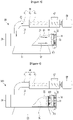
- FIG. 1 illustrates a schematic perspective view of a minute cutting apparatus for a super absorbent polymer hydrogel using a pump according to a first embodiment of the present invention
- FIG. 2 illustrates a schematic side view showing the minute cutting apparatus of FIG. 1
- FIG. 3 illustrates a schematic exploded side view of main parts showing the minute cutting apparatus of FIG. 2 .
- the minute cutting apparatus for the super absorbent polymer hydrogel using the pump includes a barrel body 10 in which a transfer space 11 through which the hydrogel is transferred is formed, a pumping unit 60 installed at an upper portion of the barrel body 10 to supply a pressing force to the transfer space 11, a rotation shaft 20 rotatably installed in the conveying space 11 of the barrel body 10, a cutter member 40 installed on the rotation shaft 20 to pulverize the hydrogel transferred through the pressing force generated in the transfer space 11, and a perforated plate 50 installed in the barrel body 10 to discharge the hydrogel pulverized by the cutter member 40 to the outside of the barrel body 10.
- the barrel body 10 may be installed in a state in which the transfer space 11 through which the hydrogel is transferred is formed along a longitudinal direction and supported on a bottom surface thereof.
- a support base 13 may protrude from a lower portion of the barrel body 10 for being stably supported on the bottom surface thereof.
- a discharging part 14, through which hydrogel particles that are pulverized by the cutter member 40 to be described later and passed through the perforated plate 50 may be discharged, may be formed at a side of the barrel body 10.
- the rotation shaft 20 may be rotatably installed in the inner transfer space 11 of the barrel body 10.
- the rotation shaft 20 may be installed to be rotatable in the longitudinal direction of the transfer space 11 inside the barrel body 10. As such, the rotation shaft 20 is installed to provide a rotational force to the cutter member 40 to be described later to properly pulverize the hydrogel.
- the rotation shaft 20 may be installed to have a first end thereof connected to a driving shaft of a driving motor 30 so as to be rotatable in one direction or in a reverse direction inside the barrel body 10.
- the driving motor 30 is installed at one side of the barrel body 10 in a state in which the driving shaft is connected to a first end of the rotation shaft 20, and thus a rotational driving force may be provided such that the rotation shaft 20 rotates at an appropriate rotational speed in one direction or in a reverse direction depending on an amount of the hydrogel injected into the barrel body 10.
- the cutter member 40 may be installed on the rotation shaft 20.
- the cutter member 40 which is rotatably installed at a position of the rotation shaft 20 corresponding to the discharge part 14 formed on the barrel body 10, may be installed to properly pulverize the hydrogel transferred from the transfer space 11 of the barrel body 10 by a pressing force 62 of the pumping unit 60.
- the cutter member 40 may be installed to protrude in a circular shape at an end of the rotation shaft 20, and may be installed to appropriately pulverize the hydrogel moving in a direction of the discharge part 14 from the inside of the barrel body 10.
- the cutter member 40 is exemplarily described to be installed in a protruding state at the end of the rotation shaft 20, but the present invention is not limited thereto, and a plurality of cutter members 40 may be installed to be spaced apart from each other at the end of the rotation shaft 20.
- the perforated plate 50 is installed at a position of the barrel body 10 corresponding to the discharge part 14, and a plurality of cutting holes may be formed therein.
- the hydrogel pulverized by the cutter member 40 is pressed and moved inside the barrel body 10 by a pressing force generated in the pumping unit 60, thereby being stably discharged through the cutting holes of the perforated plate 50 to perform a cutting process.
- the pumping unit 60 may be installed in the barrel body 10 to provide a pressing force for transferring the hydrogel.
- the pumping unit 60 includes a connection passage 61 installed at an upper portion of the barrel body 10 in communication with the transfer space 11, a body portion 63 connected to and fixed to the connection passage 61, and a rotor portion 65 rotatably installed inside the body portion 63 to provide a pressing force to the connection passage 61.
- connection passage 61 may be installed to have a first side connected to the upper portion of the barrel body 10 and communicates with the transfer space 11, and a second side thereof connected to the body portion 63.
- connection passage 61 which is connected to the body portion 63 in a state of protruding from the upper side of the barrel body 10, may support a state in which the body portion 63 is installed on an upper side of the barrel body 10.
- connection passage 61 may be formed of a steel material to support the body portion 63, or may be connected to the body portion 63 while being installed on a support frame (not illustrated).
- the body portion 63 which is installed at an upper portion of the barrel body 10 in a state of being connected to the connection passage 61, may have an installation space in which the rotor portion 65 is installed therein.
- the body portion 63 may be installed at an upper side of the barrel body 10 in a state of being connected to the connection passage 61 in various shapes such as a cylindrical shape or a polygonal shape.
- connection passage 61 is exemplarily described to be bent to connect the body portion 63 and the barrel body 10 to each other, but may be formed to have a linear shape when an installation position of the pumping unit 60 is changed.
- An injection hopper 67 for injecting the hydrogel may be installed at an upper portion of the body portion 63.
- the injection hopper 67 is not necessarily limited to being installed on the upper side of the body portion 63, and may be installed on a side surface of the body portion 63.
- the injection hopper 67 may be installed at a rear side of the body portion 63 when a position of a pumping motor 64 is changed.
- the hydrogel may be moved through the connection passage 61 depending on an operation of the rotor portion 65 to be described later to be supplied to the inside of the barrel body 10 in a state of being supplied to the inside of the body portion 63 through the injection hopper 67.
- the rotor portion 65 which is installed in the internal installation space of the body portion 63, may be selectively driven depending on an operation control of a user, and may be installed to supply a pumping force to the connection passage 61.
- the pumping unit 60 may have the spiral rotor portion 65 rotatably installed inside the body portion 10, to be applied as a type of progressive cavity pump that provides a pumping force that exceeds a pressure of the hydrogel.
- the rotor portion 65 may be rotatably installed inside the body portion 63 by a rotational force of the pumping motor 64.
- a rotor screw 68 may be installed between the rotor portion 65 and the pumping motor 64.
- the rotor screw 68 which is installed inside the body portion 63 may be installed inside the body portion 63 at a position where the injection hopper 67 is installed to transfer a rotational force of the pumping motor 64 to the rotor portion 65. Accordingly, the hydrogel may be pumped more stably in the pumping unit 60 to be transferred to the inside of the barrel body 10.
- the hydrogel may be pulverized by the cutter member 40 in the state of being supplied through the injection hopper 67 and moved to the inside of the barrel body 10 by the pumping force of the rotor portion 65.
- the hydrogel is further moved by the pressing force in the transfer space in the state of being pulverized by the cutter member 40 to be properly cut while passing through the perforated plate 50.
- the hydrogel may be cut while being pressed by a uniform pressing force on the entire side surface of the perforated plate 50 by the pumping force of the pumping unit 60 in an operation of being cut in the perforated plate 50.
- the hydrogel may be pressed on the side surface of the perforated plate 50 in a state of being completely uniformly filled in the inner space of the barrel body 10 by a pumping pressure of the pumping unit 60. Accordingly, since the hydrogel is uniformly pressed over an entire side area of the perforated plate 50, the hydrogel may be cut in a uniformly pressed state, thereby improving preparing quality of the super absorbent polymer.
- FIG. 4 illustrates a schematic exploded side view of main parts showing a minute cutting apparatus for a super absorbent polymer hydrogel using a pump according to a second embodiment of the present invention.
- the same reference numerals as those of FIG. 1 to FIG. 3 denote the same or similar members having the same or similar functions. Hereinafter, detailed descriptions of the same reference numerals will be omitted.
- a plurality of cutter members 140 and a plurality of perforated plates 150 of the minute cutting apparatus 300 for the super absorbent polymer hydrogel using the pump according to the second embodiment of the present invention may be continuously installed on the rotation shaft 20.
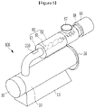
- FIG. 5 illustrates a schematic perspective view of a minute cutting apparatus for a super absorbent polymer hydrogel using a pump according to a third embodiment of the present invention.
- the same reference numerals as those of FIG. 1 to FIG. 4 denote the same or similar members having the same or similar functions. Hereinafter, detailed descriptions of the same reference numerals will be omitted.
- a display window 210 capable of confirming a connection passage may be installed in the minute cutting apparatus 300 for the super absorbent polymer hydrogel using the pump according to the third embodiment of the present invention.
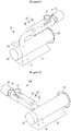
- FIG. 6 illustrates a schematic perspective view of a minute cutting apparatus for a super absorbent polymer hydrogel using a pump according to a fourth embodiment of the present invention.
- the same reference numerals as those of FIG. 1 to FIG. 5 denote the same or similar members having the same or similar functions. Hereinafter, detailed descriptions of the same reference numerals will be omitted.
- a pressure sensor 310 for sensing whether an internal pressure of the connection passage 61 is within a predetermined pressure range may be installed in the minute cutting apparatus 400 for the super absorbent polymer hydrogel using the pump according to the fourth embodiment of the present invention.
- the pressure sensor 310 may be installed to warn a user by recognizing a closed state such as clogging or a damaged state such as perforation when the internal pressure of the connection passage 61 is sensed as an abnormal pressure that exceeds a predetermined pressure. Accordingly, it is possible to quickly troubleshoot an abnormal operation and extend a service life.
- FIG. 7 illustrates a schematic perspective view of a minute cutting apparatus for a super absorbent polymer hydrogel using a pump according to a fifth embodiment of the present invention.
- the same reference numerals as those of FIG. 1 to FIG. 6 denote the same or similar members having the same or similar functions. Hereinafter, detailed descriptions of the same reference numerals will be omitted.
- a pumping unit 60 of the minute cutting apparatus 500 for the super absorbent polymer hydrogel using the pump according to the fifth embodiment of the present invention may be installed at a side surface of the barrel body 10, and the connection passage 61 may be connected to the side surface of the barrel body 10.
- the hydrogel may be supplied from the side surface of the barrel body 10 to the inside of the barrel body 10.
- the connection passage 61 is exemplarily described to be connected to the side surface of the barrel body 10, but it may be connected to a rear position of the barrel body 10 when a position of the driving motor 30 is changed.
Landscapes
- Engineering & Computer Science (AREA)
- Mechanical Engineering (AREA)
- Chemical & Material Sciences (AREA)
- Food Science & Technology (AREA)
- Dispersion Chemistry (AREA)
- Health & Medical Sciences (AREA)
- Chemical Kinetics & Catalysis (AREA)
- Medicinal Chemistry (AREA)
- Polymers & Plastics (AREA)
- Organic Chemistry (AREA)
- Manufacturing & Machinery (AREA)
- Crushing And Pulverization Processes (AREA)
Abstract
Description
- This application claims priority to and the benefit of
Korean Patent Application No. 10-2019-0130240, filed in the Korean Intellectual Property Office on October 18, 2019 Korean Patent Application No. 10-2020-0134112, filed in the Korean Intellectual Property Office on October 16, 2020 - The present invention relates to a minute cutting apparatus for a super absorbent polymer hydrogel using a pump, which uniformly cuts the hydrogel.
- A super absorbent polymer (SAP) is a synthetic polymer material with a function of being capable of absorbing moisture of 500 to 1000 times its own weight, and is referred to as a super absorbency material (SAM), an absorbent gel material (AGM), or the like by each developer. The above-described super absorbent polymer has begun to be put into practical use as a sanitary product, and is currently widely used as a material such as a soil repair agent for gardening, a water supply material for civil works or construction, a sheet for seedlings, a freshness maintenance agent in the food distribution field, and a material for a poultice in addition to hygiene products such as paper diapers for children.
- A hydrogel or hydrogel polymer obtained through the polymerization reaction as described above is generally pulverized after a drying process and then is commercially available as a powdery product is known. It is important to increase the surface area of the hydrogel polymer as much as possible in order to efficiently perform the drying step. Accordingly, a method of increasing a surface area of the hydrogel polymer to be dried by simply pulverizing the hydrogel polymer that is polymerized through thermal polymerization or photopolymerization may be considered in order to increase the surface area of the hydrogel polymer before the drying process as much as possible. A process of first pulverizing the hydrogel polymer after polymerization has been disclosed in order to increase the surface area of the hydrogel polymer as described above.
- A chopper is mainly used in the first pulverizing process of the hydrogel.
- Such a chopper includes a screw for moving the hydrogel, a barrel including a spiral, a cutter blade for cutting the hydrogel, and a perforated plate from which the cut hydrogel is discharged.
- In such a conventional chopper, a moving direction of hydrogel particles injected into a barrel and a screw is horizontal. Accordingly, a pressure applied to the hydrogel particles at the position where a perforated plate is positioned is not uniform, and a working pressure at a lower position of the barrel is greater than that at an upper portion thereof, so that uniform cutting is not performed in the perforated plate.
- As described above, when sizes of the minutely cut particles of the hydrogel are not uniform, non-uniform drying may occur for each particle during a drying process of the hydrogel, resulting in excessive drying or under-drying.
- Herein, the excessively dried product of the hydrogel may generate a large amount of fine powder in a preparing process of the super absorbent polymer, thereby causing a problem in the preparing process. In addition, the under-dried product of the hydrogel has a problem in that it is difficult to prepare a smooth super absorbent polymer in processes such as pulverization or classification as well as physical properties of the prepared super absorbent polymer.
- An embodiment of the present invention has been made in an effort to provide a minute cutting apparatus for a super absorbent polymer hydrogel using a pump, that is capable of uniform cutting of the hydrogel, thereby improving manufacturing quality of the super absorbent polymer.
- An embodiment of the present invention provides a minute cutting apparatus for a super absorbent polymer hydrogel using a pump, including: a barrel body in which a transfer space through which the hydrogel is transferred is formed; a pumping unit installed in the barrel body to supply a pressing force to the transfer space, a rotation shaft rotatably installed in the transfer space of the barrel body; a driving motor configured to provide a rotational driving force to the rotation shaft; a cutter member installed on the rotation shaft to pulverize the hydrogel transferred by the pressing force in the transfer space; and a perforated plate installed in the barrel body to discharge the hydrogel pulverized by the cutter member to an outside of the barrel body.
- The barrel body may have a transfer space in which the hydrogel is transferred, and the pumped pressing force may be supplied to an inside of the transfer space by being connected to the pumping unit at an upper portion thereof.
- The pumping unit may include: a connection passage installed on an upper portion of the barrel body to be in communication with the transfer space; a body portion fixedly installed in the connection passage; and a spiral rotor portion rotatably installed inside the body portion to provide a pressing force to the connection passage.
- An injection hopper into which the hydrogel is injected may be installed at an upper portion of the body portion.
- A plurality of cutter members and a plurality of perforated plates may be continuously installed on the rotation shaft.
- A display window capable of checking an inside may be installed in the connection passage.
- The minute cutting apparatus may further include a pressure sensor installed in the connection passage to sense whether or not an internal pressure is within a predetermined pressure range.
- According to an embodiment of the present invention, the hydrogel may be pressed against the side surface of the perforated plate while being filled in an entirely uniform state in the inner space of the barrel body by the pumping force of the pump unit. Accordingly, the hydrogel is uniformly pressed over an entire side area of the perforated plate, and thus the hydrogel may be cut in a uniformly pressed state, thereby improving preparing quality of the super absorbent polymer.
-
-
FIG. 1 illustrates a schematic perspective view of a minute cutting apparatus for a super absorbent polymer hydrogel using a pump according to a first embodiment of the present invention. -
FIG. 2 illustrates a schematic side view showing the minute cutting apparatus ofFIG. 1 . -
FIG. 3 illustrates a schematic exploded side view of main parts showing the minute cutting apparatus ofFIG. 2 . -
FIG. 4 illustrates a schematic exploded side view of main parts showing a minute cutting apparatus for a super absorbent polymer hydrogel using a pump according to a second embodiment of the present invention. -
FIG. 5 illustrates a schematic perspective view of a minute cutting apparatus for a super absorbent polymer hydrogel using a pump according to a third embodiment of the present invention. -
FIG. 6 illustrates a schematic perspective view of a minute cutting apparatus for a super absorbent polymer hydrogel using a pump according to a fourth embodiment of the present invention. -
FIG. 7 illustrates a schematic perspective view of a minute cutting apparatus for a super absorbent polymer hydrogel using a pump according to a fifth embodiment of the present invention. - Hereinafter, the present invention will be described more fully with reference to the accompanying drawings, in which embodiments of the invention are shown. As those skilled in the art would realize, the described embodiments may be modified in various different ways, all without departing from the scope of the present invention. The drawings and description are to be regarded as illustrative in nature and not restrictive. Like reference numerals designate like elements throughout the specification.
- A minute cutting apparatus for a super absorbent polymer hydrogel using a pump, which is described below, may be installed to improve physical properties by more precisely forming the super absorbent polymer into a particle shape. This will be described in detail below with reference to the drawings.
-
FIG. 1 illustrates a schematic perspective view of a minute cutting apparatus for a super absorbent polymer hydrogel using a pump according to a first embodiment of the present invention,FIG. 2 illustrates a schematic side view showing the minute cutting apparatus ofFIG. 1 , andFIG. 3 illustrates a schematic exploded side view of main parts showing the minute cutting apparatus ofFIG. 2 . - As illustrated in
FIG. 1 to FIG. 3 , according to the first embodiment of the present invention, the minute cutting apparatus for the super absorbent polymer hydrogel using the pump includes abarrel body 10 in which atransfer space 11 through which the hydrogel is transferred is formed, apumping unit 60 installed at an upper portion of thebarrel body 10 to supply a pressing force to thetransfer space 11, arotation shaft 20 rotatably installed in theconveying space 11 of thebarrel body 10, acutter member 40 installed on therotation shaft 20 to pulverize the hydrogel transferred through the pressing force generated in thetransfer space 11, and aperforated plate 50 installed in thebarrel body 10 to discharge the hydrogel pulverized by thecutter member 40 to the outside of thebarrel body 10. - The
barrel body 10 may be installed in a state in which thetransfer space 11 through which the hydrogel is transferred is formed along a longitudinal direction and supported on a bottom surface thereof. - A
support base 13 may protrude from a lower portion of thebarrel body 10 for being stably supported on the bottom surface thereof. - A
discharging part 14, through which hydrogel particles that are pulverized by thecutter member 40 to be described later and passed through theperforated plate 50 may be discharged, may be formed at a side of thebarrel body 10. - The
rotation shaft 20 may be rotatably installed in theinner transfer space 11 of thebarrel body 10. - The
rotation shaft 20 may be installed to be rotatable in the longitudinal direction of thetransfer space 11 inside thebarrel body 10. As such, therotation shaft 20 is installed to provide a rotational force to thecutter member 40 to be described later to properly pulverize the hydrogel. - The
rotation shaft 20 may be installed to have a first end thereof connected to a driving shaft of a drivingmotor 30 so as to be rotatable in one direction or in a reverse direction inside thebarrel body 10. - The driving
motor 30 is installed at one side of thebarrel body 10 in a state in which the driving shaft is connected to a first end of therotation shaft 20, and thus a rotational driving force may be provided such that therotation shaft 20 rotates at an appropriate rotational speed in one direction or in a reverse direction depending on an amount of the hydrogel injected into thebarrel body 10. - Meanwhile, the
cutter member 40 may be installed on therotation shaft 20. - The
cutter member 40, which is rotatably installed at a position of therotation shaft 20 corresponding to thedischarge part 14 formed on thebarrel body 10, may be installed to properly pulverize the hydrogel transferred from thetransfer space 11 of thebarrel body 10 by apressing force 62 of thepumping unit 60. - The
cutter member 40 may be installed to protrude in a circular shape at an end of therotation shaft 20, and may be installed to appropriately pulverize the hydrogel moving in a direction of thedischarge part 14 from the inside of thebarrel body 10. Thecutter member 40 is exemplarily described to be installed in a protruding state at the end of therotation shaft 20, but the present invention is not limited thereto, and a plurality ofcutter members 40 may be installed to be spaced apart from each other at the end of therotation shaft 20. - The
perforated plate 50 is installed at a position of thebarrel body 10 corresponding to thedischarge part 14, and a plurality of cutting holes may be formed therein. - Accordingly, the hydrogel pulverized by the
cutter member 40 is pressed and moved inside thebarrel body 10 by a pressing force generated in thepumping unit 60, thereby being stably discharged through the cutting holes of theperforated plate 50 to perform a cutting process. - Meanwhile, the
pumping unit 60 may be installed in thebarrel body 10 to provide a pressing force for transferring the hydrogel. - The
pumping unit 60 includes aconnection passage 61 installed at an upper portion of thebarrel body 10 in communication with thetransfer space 11, abody portion 63 connected to and fixed to theconnection passage 61, and arotor portion 65 rotatably installed inside thebody portion 63 to provide a pressing force to theconnection passage 61. - The
connection passage 61 may be installed to have a first side connected to the upper portion of thebarrel body 10 and communicates with thetransfer space 11, and a second side thereof connected to thebody portion 63. - The
connection passage 61, which is connected to thebody portion 63 in a state of protruding from the upper side of thebarrel body 10, may support a state in which thebody portion 63 is installed on an upper side of thebarrel body 10. - The
connection passage 61 may be formed of a steel material to support thebody portion 63, or may be connected to thebody portion 63 while being installed on a support frame (not illustrated). - The
body portion 63, which is installed at an upper portion of thebarrel body 10 in a state of being connected to theconnection passage 61, may have an installation space in which therotor portion 65 is installed therein. Thebody portion 63 may be installed at an upper side of thebarrel body 10 in a state of being connected to theconnection passage 61 in various shapes such as a cylindrical shape or a polygonal shape. - The
connection passage 61 is exemplarily described to be bent to connect thebody portion 63 and thebarrel body 10 to each other, but may be formed to have a linear shape when an installation position of thepumping unit 60 is changed. - An
injection hopper 67 for injecting the hydrogel may be installed at an upper portion of thebody portion 63. Theinjection hopper 67 is not necessarily limited to being installed on the upper side of thebody portion 63, and may be installed on a side surface of thebody portion 63. In addition, theinjection hopper 67 may be installed at a rear side of thebody portion 63 when a position of a pumpingmotor 64 is changed. - Accordingly, the hydrogel may be moved through the
connection passage 61 depending on an operation of therotor portion 65 to be described later to be supplied to the inside of thebarrel body 10 in a state of being supplied to the inside of thebody portion 63 through theinjection hopper 67. - The
rotor portion 65, which is installed in the internal installation space of thebody portion 63, may be selectively driven depending on an operation control of a user, and may be installed to supply a pumping force to theconnection passage 61. - According to the present embodiment, the
pumping unit 60 may have thespiral rotor portion 65 rotatably installed inside thebody portion 10, to be applied as a type of progressive cavity pump that provides a pumping force that exceeds a pressure of the hydrogel. - The
rotor portion 65 may be rotatably installed inside thebody portion 63 by a rotational force of the pumpingmotor 64. - A
rotor screw 68 may be installed between therotor portion 65 and the pumpingmotor 64. - The
rotor screw 68 which is installed inside thebody portion 63 may be installed inside thebody portion 63 at a position where theinjection hopper 67 is installed to transfer a rotational force of the pumpingmotor 64 to therotor portion 65. Accordingly, the hydrogel may be pumped more stably in thepumping unit 60 to be transferred to the inside of thebarrel body 10. - As described above, the hydrogel may be pulverized by the
cutter member 40 in the state of being supplied through theinjection hopper 67 and moved to the inside of thebarrel body 10 by the pumping force of therotor portion 65. - Subsequently, the hydrogel is further moved by the pressing force in the transfer space in the state of being pulverized by the
cutter member 40 to be properly cut while passing through theperforated plate 50. Herein, the hydrogel may be cut while being pressed by a uniform pressing force on the entire side surface of theperforated plate 50 by the pumping force of thepumping unit 60 in an operation of being cut in theperforated plate 50. - That is, the hydrogel may be pressed on the side surface of the
perforated plate 50 in a state of being completely uniformly filled in the inner space of thebarrel body 10 by a pumping pressure of thepumping unit 60. Accordingly, since the hydrogel is uniformly pressed over an entire side area of theperforated plate 50, the hydrogel may be cut in a uniformly pressed state, thereby improving preparing quality of the super absorbent polymer. -
FIG. 4 illustrates a schematic exploded side view of main parts showing a minute cutting apparatus for a super absorbent polymer hydrogel using a pump according to a second embodiment of the present invention. The same reference numerals as those ofFIG. 1 to FIG. 3 denote the same or similar members having the same or similar functions. Hereinafter, detailed descriptions of the same reference numerals will be omitted. - As illustrated in
FIG. 4 , a plurality ofcutter members 140 and a plurality ofperforated plates 150 of the minute cutting apparatus 300 for the super absorbent polymer hydrogel using the pump according to the second embodiment of the present invention may be continuously installed on therotation shaft 20. - Accordingly, it is possible to pulverize the hydrogel by using the
cutter members 140 according to a rotational operation of therotation shaft 20, so that an effective hydrogel pulverization operation may be performed. -
FIG. 5 illustrates a schematic perspective view of a minute cutting apparatus for a super absorbent polymer hydrogel using a pump according to a third embodiment of the present invention. The same reference numerals as those ofFIG. 1 to FIG. 4 denote the same or similar members having the same or similar functions. Hereinafter, detailed descriptions of the same reference numerals will be omitted. - As illustrated in
FIG. 5 , adisplay window 210 capable of confirming a connection passage may be installed in the minute cutting apparatus 300 for the super absorbent polymer hydrogel using the pump according to the third embodiment of the present invention. - Accordingly, it is possible to easily check an abnormal closing state due to clogging of the
connection passage 61 and a moving state of the hydrogel, so that quick troubleshooting may be performed. -
FIG. 6 illustrates a schematic perspective view of a minute cutting apparatus for a super absorbent polymer hydrogel using a pump according to a fourth embodiment of the present invention. The same reference numerals as those ofFIG. 1 to FIG. 5 denote the same or similar members having the same or similar functions. Hereinafter, detailed descriptions of the same reference numerals will be omitted. - As illustrated in
FIG. 6 , apressure sensor 310 for sensing whether an internal pressure of theconnection passage 61 is within a predetermined pressure range may be installed in theminute cutting apparatus 400 for the super absorbent polymer hydrogel using the pump according to the fourth embodiment of the present invention. - The
pressure sensor 310 may be installed to warn a user by recognizing a closed state such as clogging or a damaged state such as perforation when the internal pressure of theconnection passage 61 is sensed as an abnormal pressure that exceeds a predetermined pressure. Accordingly, it is possible to quickly troubleshoot an abnormal operation and extend a service life. -
FIG. 7 illustrates a schematic perspective view of a minute cutting apparatus for a super absorbent polymer hydrogel using a pump according to a fifth embodiment of the present invention. The same reference numerals as those ofFIG. 1 to FIG. 6 denote the same or similar members having the same or similar functions. Hereinafter, detailed descriptions of the same reference numerals will be omitted. - As illustrated in
FIG. 7 , apumping unit 60 of theminute cutting apparatus 500 for the super absorbent polymer hydrogel using the pump according to the fifth embodiment of the present invention may be installed at a side surface of thebarrel body 10, and theconnection passage 61 may be connected to the side surface of thebarrel body 10. - Accordingly, the hydrogel may be supplied from the side surface of the
barrel body 10 to the inside of thebarrel body 10. In the present embodiment, theconnection passage 61 is exemplarily described to be connected to the side surface of thebarrel body 10, but it may be connected to a rear position of thebarrel body 10 when a position of the drivingmotor 30 is changed. - While this invention has been described in connection with what is presently considered to be practical embodiments, it is to be understood that the invention is not limited to the disclosed embodiments, but, on the contrary, is intended to cover various modifications and equivalent arrangements included within the scope of the appended claims.
- Description of
Symbols 10 barrel body 11 transfer space 13 support base 20 rotation shaft 30 driving motor 40, 140 cutter member 50, 150 perforated plate 60 pumping unit 61 connection passage 63 body portion 64 pumping motor 65 rotor portion 67 injection hopper 68 rotor screw 210 display window 310 pressure sensor
Claims (7)
- A minute cutting apparatus for a superabsorbent polymer hydrogel using a pump, comprising:a barrel body comprising a transfer space through which the hydrogel is transferred;a pumping unit located in the transfer space of the barrel body that is configured to supply a pressing force to the transfer space;a rotation shaft which rotates in the transfer space of the barrel body;a driving motor configured to provide a rotational driving force to the rotation shaft;a cutter member attached to the rotation shaft configured to pulverize the hydrogel transferred by the pressing force in the transfer space; anda perforated plate located in the transfer space of the barrel body to discharge the hydrogel pulverized by the cutter member to an outside of the barrel body.
- A minute cutting apparatus of claim 1, wherein
the pressing force is supplied from an upper portion of the barrel body into inside of the transfer space. - The minute cutting apparatus of claim 2, wherein
the pumping unit includes:a connection passage connected to an upper portion of the barrel body to be in communication with the transfer space;a body portion attached to a side of the connection passage that is an opposite side of the connection passage to which the barrel body is attached; anda spiral rotor portion located inside the body portion and configured to provide a pressing force to the connection passage. - The minute cutting apparatus of claim 3, further comprising an injection hopper into which the hydrogel is injected and located at an upper portion of the body portion.
- The minute cutting apparatus of claim 1, further comprising a plurality of cutter members and a plurality of perforated plates located in the transfer space of the barrel body and attached to the rotation shaft.
- The minute cutting apparatus of claim 3, further comprising a display window capable of checking an inside located at the connection passage.
- The minute cutting apparatus of claim 1, further comprising a pressure sensor located at the connection passage to check whether or not an internal pressure is within a predetermined pressure range.
Applications Claiming Priority (2)
| Application Number | Priority Date | Filing Date | Title |
|---|---|---|---|
| KR20190130240 | 2019-10-18 | ||
| PCT/KR2020/014189 WO2021075921A1 (en) | 2019-10-18 | 2020-10-16 | Superabsorbent polymer hydrogel chopper using pump |
Publications (3)
| Publication Number | Publication Date |
|---|---|
| EP4000736A1 true EP4000736A1 (en) | 2022-05-25 |
| EP4000736A4 EP4000736A4 (en) | 2022-09-14 |
| EP4000736B1 EP4000736B1 (en) | 2025-12-03 |
Family
ID=75721322
Family Applications (1)
| Application Number | Title | Priority Date | Filing Date |
|---|---|---|---|
| EP20876176.7A Active EP4000736B1 (en) | 2019-10-18 | 2020-10-16 | Superabsorbent polymer hydrogel chopper using pump |
Country Status (3)
| Country | Link |
|---|---|
| EP (1) | EP4000736B1 (en) |
| KR (1) | KR20210046570A (en) |
| CN (1) | CN114340798B (en) |
Cited By (3)
| Publication number | Priority date | Publication date | Assignee | Title |
|---|---|---|---|---|
| EP3984711A4 (en) * | 2019-11-21 | 2022-08-24 | LG Chem, Ltd. | COMPOSITE CHOPPER FOR SUPERABSORBENT HYDROGEL |
| EP4197639A4 (en) * | 2021-06-18 | 2024-01-24 | Lg Chem, Ltd. | MICRONIZATION DEVICE FOR HYDROGEL MADE OF SUPERABSORBENT POLYMER |
| US12521726B2 (en) | 2021-06-18 | 2026-01-13 | Lg Chem, Ltd. | Micronizing apparatus for hydrogel of super absorbent polymer |
Family Cites Families (17)
| Publication number | Priority date | Publication date | Assignee | Title |
|---|---|---|---|---|
| WO1998041390A1 (en) * | 1997-03-20 | 1998-09-24 | Koch Feed Technologies Company | Extrusion apparatus |
| JP2002177807A (en) * | 2000-12-15 | 2002-06-25 | Toagosei Co Ltd | Method for reducing grain size of hydrated polymer gel |
| JP4034248B2 (en) * | 2003-07-11 | 2008-01-16 | 株式会社神戸製鋼所 | Quantitative supply apparatus, kneading extrusion equipment, quantitative supply method, kneading extrusion method |
| US7591974B2 (en) * | 2006-01-25 | 2009-09-22 | Absorbent Technologies, Inc. | Methods for producing superabsorbent polymers for use in agricultural applications |
| CN203357498U (en) * | 2013-06-04 | 2013-12-25 | 珠海得米新材料有限公司 | Composite cutting system for gel |
| EP3520978B1 (en) * | 2013-08-28 | 2020-11-04 | Nippon Shokubai Co., Ltd. | Polyacrylic acid (salt)-based water absorbent resin powder |
| US9750264B2 (en) * | 2013-10-22 | 2017-09-05 | Rome, Ltd. | Perforated plate for meat grinding reclamation system |
| CN106164151B (en) * | 2014-08-29 | 2018-03-02 | 株式会社Lg化学 | Composite material with improved mechanical properties and moldings comprising the same |
| CN204278300U (en) * | 2014-10-11 | 2015-04-22 | 宁波大学 | A kind of plastic granulator of combustion gas |
| KR101613249B1 (en) * | 2014-11-14 | 2016-04-18 | 주식회사 엘지화학 | Superadsorbent resin shredding device |
| CN204701022U (en) * | 2015-06-05 | 2015-10-14 | 东莞市能路塑胶模具有限公司 | A kind of environment-friendly type plastic comminutor |
| CN204869324U (en) * | 2015-08-28 | 2015-12-16 | 方瑞庭 | Dustless manufacturing installation of aminoplast moulding compound |
| CN206030293U (en) * | 2016-08-30 | 2017-03-22 | 陕西国防工业职业技术学院 | Super absorbent polymer resin particles apparatus for producing |
| KR101847180B1 (en) * | 2017-12-08 | 2018-04-09 | 허수범 | Manufacturing apparatus of foam-agent master batch and foam-agent master batch manufactur by using the apparatus |
| CN208975987U (en) * | 2018-09-28 | 2019-06-14 | 深圳市鑫威电子材料有限公司 | A kind of casting glue production equipment |
| US11975335B2 (en) * | 2019-09-19 | 2024-05-07 | Lg Chem, Ltd. | Super absorbent polymer hydrogel shredding device |
| KR20210062459A (en) * | 2019-11-21 | 2021-05-31 | 주식회사 엘지화학 | Complex minute cutting apparatus for super absorbent polymer hydrous gel |
-
2020
- 2020-10-16 CN CN202080060079.0A patent/CN114340798B/en active Active
- 2020-10-16 EP EP20876176.7A patent/EP4000736B1/en active Active
- 2020-10-16 KR KR1020200134112A patent/KR20210046570A/en not_active Ceased
Cited By (4)
| Publication number | Priority date | Publication date | Assignee | Title |
|---|---|---|---|---|
| EP3984711A4 (en) * | 2019-11-21 | 2022-08-24 | LG Chem, Ltd. | COMPOSITE CHOPPER FOR SUPERABSORBENT HYDROGEL |
| US12251856B2 (en) | 2019-11-21 | 2025-03-18 | Lg Chem, Ltd. | Complex minute cutting apparatus for super absorbent polymer hydrogel |
| EP4197639A4 (en) * | 2021-06-18 | 2024-01-24 | Lg Chem, Ltd. | MICRONIZATION DEVICE FOR HYDROGEL MADE OF SUPERABSORBENT POLYMER |
| US12521726B2 (en) | 2021-06-18 | 2026-01-13 | Lg Chem, Ltd. | Micronizing apparatus for hydrogel of super absorbent polymer |
Also Published As
| Publication number | Publication date |
|---|---|
| EP4000736A4 (en) | 2022-09-14 |
| EP4000736B1 (en) | 2025-12-03 |
| CN114340798B (en) | 2023-10-31 |
| KR20210046570A (en) | 2021-04-28 |
| CN114340798A (en) | 2022-04-12 |
Similar Documents
| Publication | Publication Date | Title |
|---|---|---|
| US12491662B2 (en) | Minute cutting apparatus for super absorbent polymer hydrogel using pump | |
| JP7282438B2 (en) | Water-containing gel shredder for super absorbent polymer | |
| EP4000736B1 (en) | Superabsorbent polymer hydrogel chopper using pump | |
| US12251856B2 (en) | Complex minute cutting apparatus for super absorbent polymer hydrogel | |
| EP4011576B1 (en) | Superabsorbent polymer hydrogel chopper | |
| EP2117796A1 (en) | Process and apparatus for treatment of a material | |
| ITBS20100159A1 (en) | BRAIDING MACHINE FOR LITTER PRODUCTS | |
| US20150272078A1 (en) | Method of producing animal litter | |
| KR102468197B1 (en) | Minute cutting apparatus for super absorbent polymer hydrous gel | |
| KR20250081347A (en) | Hole plate for chopper and chopper provided with the same | |
| CN203971998U (en) | A kind of feeding back device of plastic grain pulverizer | |
| KR20160020864A (en) | Superadsorbent resin shredding device | |
| EP3485211B1 (en) | Apparatus and process for drying and crushing a watery polymer gel | |
| CN112166837B (en) | Biomass straw crusher | |
| KR101613249B1 (en) | Superadsorbent resin shredding device | |
| CN209696842U (en) | A kind of solid fermentation Feed Manufacturing granulator | |
| BR112022006153B1 (en) | DETAIL CUTTING APPARATUS FOR SUPERABSORBENT HYDROGEL POLYMER USING A PUMP | |
| KR20210110169A (en) | Minute cutting apparatus for super absorbent polymer hydrous gel | |
| RU145601U1 (en) | DEVICE FOR PREPARING SUBSTRATE | |
| CN104224541A (en) | Auger-type granulator | |
| KR20190030061A (en) | Drying apparatus for absorbent polymer and drying method using the same | |
| KR20190038120A (en) | Extruding molding machine | |
| CN111066502A (en) | Forage grass rubbing crusher for agricultural machine |
Legal Events
| Date | Code | Title | Description |
|---|---|---|---|
| STAA | Information on the status of an ep patent application or granted ep patent |
Free format text: STATUS: THE INTERNATIONAL PUBLICATION HAS BEEN MADE |
|
| PUAI | Public reference made under article 153(3) epc to a published international application that has entered the european phase |
Free format text: ORIGINAL CODE: 0009012 |
|
| STAA | Information on the status of an ep patent application or granted ep patent |
Free format text: STATUS: REQUEST FOR EXAMINATION WAS MADE |
|
| 17P | Request for examination filed |
Effective date: 20220216 |
|
| AK | Designated contracting states |
Kind code of ref document: A1 Designated state(s): AL AT BE BG CH CY CZ DE DK EE ES FI FR GB GR HR HU IE IS IT LI LT LU LV MC MK MT NL NO PL PT RO RS SE SI SK SM TR |
|
| REG | Reference to a national code |
Ref country code: DE Ref legal event code: R079 Ipc: B29B0007420000 Ref document number: 602020063405 Country of ref document: DE Free format text: PREVIOUS MAIN CLASS: B02C0018140000 |
|
| A4 | Supplementary search report drawn up and despatched |
Effective date: 20220812 |
|
| RIC1 | Information provided on ipc code assigned before grant |
Ipc: C08J 3/075 20060101ALI20220808BHEP Ipc: B01J 2/00 20060101ALI20220808BHEP Ipc: C08J 3/12 20060101ALI20220808BHEP Ipc: B29B 9/12 20060101ALI20220808BHEP Ipc: B29B 9/06 20060101ALI20220808BHEP Ipc: B29B 7/60 20060101ALI20220808BHEP Ipc: B29B 7/42 20060101AFI20220808BHEP |
|
| DAV | Request for validation of the european patent (deleted) | ||
| DAX | Request for extension of the european patent (deleted) | ||
| STAA | Information on the status of an ep patent application or granted ep patent |
Free format text: STATUS: EXAMINATION IS IN PROGRESS |
|
| 17Q | First examination report despatched |
Effective date: 20231024 |
|
| GRAP | Despatch of communication of intention to grant a patent |
Free format text: ORIGINAL CODE: EPIDOSNIGR1 |
|
| STAA | Information on the status of an ep patent application or granted ep patent |
Free format text: STATUS: GRANT OF PATENT IS INTENDED |
|
| RIC1 | Information provided on ipc code assigned before grant |
Ipc: B29B 7/42 20060101AFI20250617BHEP Ipc: B29B 7/60 20060101ALI20250617BHEP Ipc: B29B 9/06 20060101ALI20250617BHEP Ipc: B29B 9/12 20060101ALI20250617BHEP Ipc: C08J 3/12 20060101ALI20250617BHEP Ipc: B01J 2/00 20060101ALI20250617BHEP Ipc: C08J 3/075 20060101ALI20250617BHEP Ipc: B29C 48/365 20190101ALN20250617BHEP Ipc: B29C 48/04 20190101ALN20250617BHEP Ipc: B29C 48/345 20190101ALN20250617BHEP Ipc: B29C 48/92 20190101ALN20250617BHEP |
|
| INTG | Intention to grant announced |
Effective date: 20250627 |
|
| GRAS | Grant fee paid |
Free format text: ORIGINAL CODE: EPIDOSNIGR3 |
|
| GRAA | (expected) grant |
Free format text: ORIGINAL CODE: 0009210 |
|
| STAA | Information on the status of an ep patent application or granted ep patent |
Free format text: STATUS: THE PATENT HAS BEEN GRANTED |
|
| AK | Designated contracting states |
Kind code of ref document: B1 Designated state(s): AL AT BE BG CH CY CZ DE DK EE ES FI FR GB GR HR HU IE IS IT LI LT LU LV MC MK MT NL NO PL PT RO RS SE SI SK SM TR |
|
| REG | Reference to a national code |
Ref country code: CH Ref legal event code: F10 Free format text: ST27 STATUS EVENT CODE: U-0-0-F10-F00 (AS PROVIDED BY THE NATIONAL OFFICE) Effective date: 20251203 Ref country code: GB Ref legal event code: FG4D |
|
| REG | Reference to a national code |
Ref country code: DE Ref legal event code: R096 Ref document number: 602020063405 Country of ref document: DE |
|
| REG | Reference to a national code |
Ref country code: IE Ref legal event code: FG4D |
|
| REG | Reference to a national code |
Ref country code: NL Ref legal event code: MP Effective date: 20251203 |
|
| PG25 | Lapsed in a contracting state [announced via postgrant information from national office to epo] |
Ref country code: ES Free format text: LAPSE BECAUSE OF FAILURE TO SUBMIT A TRANSLATION OF THE DESCRIPTION OR TO PAY THE FEE WITHIN THE PRESCRIBED TIME-LIMIT Effective date: 20251203 |
|
| REG | Reference to a national code |
Ref country code: LT Ref legal event code: MG9D |
|
| PG25 | Lapsed in a contracting state [announced via postgrant information from national office to epo] |
Ref country code: NO Free format text: LAPSE BECAUSE OF FAILURE TO SUBMIT A TRANSLATION OF THE DESCRIPTION OR TO PAY THE FEE WITHIN THE PRESCRIBED TIME-LIMIT Effective date: 20260303 |
|
| PG25 | Lapsed in a contracting state [announced via postgrant information from national office to epo] |
Ref country code: FI Free format text: LAPSE BECAUSE OF FAILURE TO SUBMIT A TRANSLATION OF THE DESCRIPTION OR TO PAY THE FEE WITHIN THE PRESCRIBED TIME-LIMIT Effective date: 20251203 Ref country code: HR Free format text: LAPSE BECAUSE OF FAILURE TO SUBMIT A TRANSLATION OF THE DESCRIPTION OR TO PAY THE FEE WITHIN THE PRESCRIBED TIME-LIMIT Effective date: 20251203 |
|
| PG25 | Lapsed in a contracting state [announced via postgrant information from national office to epo] |
Ref country code: RS Free format text: LAPSE BECAUSE OF FAILURE TO SUBMIT A TRANSLATION OF THE DESCRIPTION OR TO PAY THE FEE WITHIN THE PRESCRIBED TIME-LIMIT Effective date: 20260303 |
|
| PG25 | Lapsed in a contracting state [announced via postgrant information from national office to epo] |
Ref country code: PL Free format text: LAPSE BECAUSE OF FAILURE TO SUBMIT A TRANSLATION OF THE DESCRIPTION OR TO PAY THE FEE WITHIN THE PRESCRIBED TIME-LIMIT Effective date: 20251203 |
|
| PG25 | Lapsed in a contracting state [announced via postgrant information from national office to epo] |
Ref country code: LV Free format text: LAPSE BECAUSE OF FAILURE TO SUBMIT A TRANSLATION OF THE DESCRIPTION OR TO PAY THE FEE WITHIN THE PRESCRIBED TIME-LIMIT Effective date: 20251203 |
|
| PG25 | Lapsed in a contracting state [announced via postgrant information from national office to epo] |
Ref country code: BG Free format text: LAPSE BECAUSE OF FAILURE TO SUBMIT A TRANSLATION OF THE DESCRIPTION OR TO PAY THE FEE WITHIN THE PRESCRIBED TIME-LIMIT Effective date: 20251203 |