EP4000556A1 - Dental implant body and dental implant body manufacturing method - Google Patents
Dental implant body and dental implant body manufacturing method Download PDFInfo
- Publication number
- EP4000556A1 EP4000556A1 EP20841277.5A EP20841277A EP4000556A1 EP 4000556 A1 EP4000556 A1 EP 4000556A1 EP 20841277 A EP20841277 A EP 20841277A EP 4000556 A1 EP4000556 A1 EP 4000556A1
- Authority
- EP
- European Patent Office
- Prior art keywords
- blind
- dental implant
- equal
- implant body
- ceramics sintered
- Prior art date
- Legal status (The legal status is an assumption and is not a legal conclusion. Google has not performed a legal analysis and makes no representation as to the accuracy of the status listed.)
- Granted
Links
Images

Classifications
-
- A—HUMAN NECESSITIES
- A61—MEDICAL OR VETERINARY SCIENCE; HYGIENE
- A61K—PREPARATIONS FOR MEDICAL, DENTAL OR TOILETRY PURPOSES
- A61K6/00—Preparations for dentistry
- A61K6/80—Preparations for artificial teeth, for filling teeth or for capping teeth
- A61K6/802—Preparations for artificial teeth, for filling teeth or for capping teeth comprising ceramics
- A61K6/818—Preparations for artificial teeth, for filling teeth or for capping teeth comprising ceramics comprising zirconium oxide
-
- A—HUMAN NECESSITIES
- A61—MEDICAL OR VETERINARY SCIENCE; HYGIENE
- A61C—DENTISTRY; APPARATUS OR METHODS FOR ORAL OR DENTAL HYGIENE
- A61C13/00—Dental prostheses; Making same
- A61C13/0003—Making bridge-work, inlays, implants or the like
- A61C13/0006—Production methods
-
- A—HUMAN NECESSITIES
- A61—MEDICAL OR VETERINARY SCIENCE; HYGIENE
- A61C—DENTISTRY; APPARATUS OR METHODS FOR ORAL OR DENTAL HYGIENE
- A61C13/00—Dental prostheses; Making same
- A61C13/08—Artificial teeth; Making same
-
- A—HUMAN NECESSITIES
- A61—MEDICAL OR VETERINARY SCIENCE; HYGIENE
- A61C—DENTISTRY; APPARATUS OR METHODS FOR ORAL OR DENTAL HYGIENE
- A61C8/00—Means to be fixed to the jaw-bone for consolidating natural teeth or for fixing dental prostheses thereon; Dental implants; Implanting tools
- A61C8/0012—Means to be fixed to the jaw-bone for consolidating natural teeth or for fixing dental prostheses thereon; Dental implants; Implanting tools characterised by the material or composition, e.g. ceramics, surface layer, metal alloy
-
- A—HUMAN NECESSITIES
- A61—MEDICAL OR VETERINARY SCIENCE; HYGIENE
- A61C—DENTISTRY; APPARATUS OR METHODS FOR ORAL OR DENTAL HYGIENE
- A61C8/00—Means to be fixed to the jaw-bone for consolidating natural teeth or for fixing dental prostheses thereon; Dental implants; Implanting tools
- A61C8/0018—Means to be fixed to the jaw-bone for consolidating natural teeth or for fixing dental prostheses thereon; Dental implants; Implanting tools characterised by the shape
- A61C8/0037—Details of the shape
-
- A—HUMAN NECESSITIES
- A61—MEDICAL OR VETERINARY SCIENCE; HYGIENE
- A61C—DENTISTRY; APPARATUS OR METHODS FOR ORAL OR DENTAL HYGIENE
- A61C8/00—Means to be fixed to the jaw-bone for consolidating natural teeth or for fixing dental prostheses thereon; Dental implants; Implanting tools
- A61C8/0093—Features of implants not otherwise provided for
-
- A—HUMAN NECESSITIES
- A61—MEDICAL OR VETERINARY SCIENCE; HYGIENE
- A61L—METHODS OR APPARATUS FOR STERILISING MATERIALS OR OBJECTS IN GENERAL; DISINFECTION, STERILISATION OR DEODORISATION OF AIR; CHEMICAL ASPECTS OF BANDAGES, DRESSINGS, ABSORBENT PADS OR SURGICAL ARTICLES; MATERIALS FOR BANDAGES, DRESSINGS, ABSORBENT PADS OR SURGICAL ARTICLES
- A61L27/00—Materials for grafts or prostheses or for coating grafts or prostheses
- A61L27/02—Inorganic materials
- A61L27/10—Ceramics or glasses
-
- B—PERFORMING OPERATIONS; TRANSPORTING
- B28—WORKING CEMENT, CLAY, OR STONE
- B28B—SHAPING CLAY OR OTHER CERAMIC COMPOSITIONS; SHAPING SLAG; SHAPING MIXTURES CONTAINING CEMENTITIOUS MATERIAL, e.g. PLASTER
- B28B1/00—Producing shaped prefabricated articles from the material
- B28B1/007—Producing shaped prefabricated articles from the material by freezing the material
-
- B—PERFORMING OPERATIONS; TRANSPORTING
- B28—WORKING CEMENT, CLAY, OR STONE
- B28B—SHAPING CLAY OR OTHER CERAMIC COMPOSITIONS; SHAPING SLAG; SHAPING MIXTURES CONTAINING CEMENTITIOUS MATERIAL, e.g. PLASTER
- B28B11/00—Apparatus or processes for treating or working the shaped or preshaped articles
- B28B11/24—Apparatus or processes for treating or working the shaped or preshaped articles for curing, setting or hardening
- B28B11/243—Setting, e.g. drying, dehydrating or firing ceramic articles
-
- B—PERFORMING OPERATIONS; TRANSPORTING
- B28—WORKING CEMENT, CLAY, OR STONE
- B28B—SHAPING CLAY OR OTHER CERAMIC COMPOSITIONS; SHAPING SLAG; SHAPING MIXTURES CONTAINING CEMENTITIOUS MATERIAL, e.g. PLASTER
- B28B7/00—Moulds; Cores; Mandrels
- B28B7/16—Moulds for making shaped articles with cavities or holes open to the surface, e.g. with blind holes
- B28B7/18—Moulds for making shaped articles with cavities or holes open to the surface, e.g. with blind holes the holes passing completely through the article
-
- C—CHEMISTRY; METALLURGY
- C04—CEMENTS; CONCRETE; ARTIFICIAL STONE; CERAMICS; REFRACTORIES
- C04B—LIME, MAGNESIA; SLAG; CEMENTS; COMPOSITIONS THEREOF, e.g. MORTARS, CONCRETE OR LIKE BUILDING MATERIALS; ARTIFICIAL STONE; CERAMICS; REFRACTORIES; TREATMENT OF NATURAL STONE
- C04B35/00—Shaped ceramic products characterised by their composition; Ceramics compositions; Processing powders of inorganic compounds preparatory to the manufacturing of ceramic products
- C04B35/01—Shaped ceramic products characterised by their composition; Ceramics compositions; Processing powders of inorganic compounds preparatory to the manufacturing of ceramic products based on oxide ceramics
- C04B35/48—Shaped ceramic products characterised by their composition; Ceramics compositions; Processing powders of inorganic compounds preparatory to the manufacturing of ceramic products based on oxide ceramics based on zirconium or hafnium oxides, zirconates, zircon or hafnates
- C04B35/486—Fine ceramics
-
- C—CHEMISTRY; METALLURGY
- C04—CEMENTS; CONCRETE; ARTIFICIAL STONE; CERAMICS; REFRACTORIES
- C04B—LIME, MAGNESIA; SLAG; CEMENTS; COMPOSITIONS THEREOF, e.g. MORTARS, CONCRETE OR LIKE BUILDING MATERIALS; ARTIFICIAL STONE; CERAMICS; REFRACTORIES; TREATMENT OF NATURAL STONE
- C04B38/00—Porous mortars, concrete, artificial stone or ceramic ware; Preparation thereof
- C04B38/0045—Porous mortars, concrete, artificial stone or ceramic ware; Preparation thereof by a process involving the formation of a sol or a gel, e.g. sol-gel or precipitation processes
-
- C—CHEMISTRY; METALLURGY
- C04—CEMENTS; CONCRETE; ARTIFICIAL STONE; CERAMICS; REFRACTORIES
- C04B—LIME, MAGNESIA; SLAG; CEMENTS; COMPOSITIONS THEREOF, e.g. MORTARS, CONCRETE OR LIKE BUILDING MATERIALS; ARTIFICIAL STONE; CERAMICS; REFRACTORIES; TREATMENT OF NATURAL STONE
- C04B38/00—Porous mortars, concrete, artificial stone or ceramic ware; Preparation thereof
- C04B38/0051—Porous mortars, concrete, artificial stone or ceramic ware; Preparation thereof characterised by the pore size, pore shape or kind of porosity
- C04B38/0054—Porous mortars, concrete, artificial stone or ceramic ware; Preparation thereof characterised by the pore size, pore shape or kind of porosity the pores being microsized or nanosized
-
- A—HUMAN NECESSITIES
- A61—MEDICAL OR VETERINARY SCIENCE; HYGIENE
- A61L—METHODS OR APPARATUS FOR STERILISING MATERIALS OR OBJECTS IN GENERAL; DISINFECTION, STERILISATION OR DEODORISATION OF AIR; CHEMICAL ASPECTS OF BANDAGES, DRESSINGS, ABSORBENT PADS OR SURGICAL ARTICLES; MATERIALS FOR BANDAGES, DRESSINGS, ABSORBENT PADS OR SURGICAL ARTICLES
- A61L2430/00—Materials or treatment for tissue regeneration
- A61L2430/12—Materials or treatment for tissue regeneration for dental implants or prostheses
-
- C—CHEMISTRY; METALLURGY
- C04—CEMENTS; CONCRETE; ARTIFICIAL STONE; CERAMICS; REFRACTORIES
- C04B—LIME, MAGNESIA; SLAG; CEMENTS; COMPOSITIONS THEREOF, e.g. MORTARS, CONCRETE OR LIKE BUILDING MATERIALS; ARTIFICIAL STONE; CERAMICS; REFRACTORIES; TREATMENT OF NATURAL STONE
- C04B2111/00—Mortars, concrete or artificial stone or mixtures to prepare them, characterised by specific function, property or use
- C04B2111/00474—Uses not provided for elsewhere in C04B2111/00
- C04B2111/00836—Uses not provided for elsewhere in C04B2111/00 for medical or dental applications
-
- C—CHEMISTRY; METALLURGY
- C04—CEMENTS; CONCRETE; ARTIFICIAL STONE; CERAMICS; REFRACTORIES
- C04B—LIME, MAGNESIA; SLAG; CEMENTS; COMPOSITIONS THEREOF, e.g. MORTARS, CONCRETE OR LIKE BUILDING MATERIALS; ARTIFICIAL STONE; CERAMICS; REFRACTORIES; TREATMENT OF NATURAL STONE
- C04B2235/00—Aspects relating to ceramic starting mixtures or sintered ceramic products
- C04B2235/02—Composition of constituents of the starting material or of secondary phases of the final product
- C04B2235/30—Constituents and secondary phases not being of a fibrous nature
- C04B2235/32—Metal oxides, mixed metal oxides, or oxide-forming salts thereof, e.g. carbonates, nitrates, (oxy)hydroxides, chlorides
- C04B2235/3231—Refractory metal oxides, their mixed metal oxides, or oxide-forming salts thereof
- C04B2235/3244—Zirconium oxides, zirconates, hafnium oxides, hafnates, or oxide-forming salts thereof
-
- C—CHEMISTRY; METALLURGY
- C04—CEMENTS; CONCRETE; ARTIFICIAL STONE; CERAMICS; REFRACTORIES
- C04B—LIME, MAGNESIA; SLAG; CEMENTS; COMPOSITIONS THEREOF, e.g. MORTARS, CONCRETE OR LIKE BUILDING MATERIALS; ARTIFICIAL STONE; CERAMICS; REFRACTORIES; TREATMENT OF NATURAL STONE
- C04B2235/00—Aspects relating to ceramic starting mixtures or sintered ceramic products
- C04B2235/60—Aspects relating to the preparation, properties or mechanical treatment of green bodies or pre-forms
- C04B2235/602—Making the green bodies or pre-forms by moulding
-
- C—CHEMISTRY; METALLURGY
- C04—CEMENTS; CONCRETE; ARTIFICIAL STONE; CERAMICS; REFRACTORIES
- C04B—LIME, MAGNESIA; SLAG; CEMENTS; COMPOSITIONS THEREOF, e.g. MORTARS, CONCRETE OR LIKE BUILDING MATERIALS; ARTIFICIAL STONE; CERAMICS; REFRACTORIES; TREATMENT OF NATURAL STONE
- C04B2235/00—Aspects relating to ceramic starting mixtures or sintered ceramic products
- C04B2235/60—Aspects relating to the preparation, properties or mechanical treatment of green bodies or pre-forms
- C04B2235/602—Making the green bodies or pre-forms by moulding
- C04B2235/6023—Gel casting
-
- C—CHEMISTRY; METALLURGY
- C04—CEMENTS; CONCRETE; ARTIFICIAL STONE; CERAMICS; REFRACTORIES
- C04B—LIME, MAGNESIA; SLAG; CEMENTS; COMPOSITIONS THEREOF, e.g. MORTARS, CONCRETE OR LIKE BUILDING MATERIALS; ARTIFICIAL STONE; CERAMICS; REFRACTORIES; TREATMENT OF NATURAL STONE
- C04B2235/00—Aspects relating to ceramic starting mixtures or sintered ceramic products
- C04B2235/60—Aspects relating to the preparation, properties or mechanical treatment of green bodies or pre-forms
- C04B2235/606—Drying
-
- C—CHEMISTRY; METALLURGY
- C04—CEMENTS; CONCRETE; ARTIFICIAL STONE; CERAMICS; REFRACTORIES
- C04B—LIME, MAGNESIA; SLAG; CEMENTS; COMPOSITIONS THEREOF, e.g. MORTARS, CONCRETE OR LIKE BUILDING MATERIALS; ARTIFICIAL STONE; CERAMICS; REFRACTORIES; TREATMENT OF NATURAL STONE
- C04B2235/00—Aspects relating to ceramic starting mixtures or sintered ceramic products
- C04B2235/65—Aspects relating to heat treatments of ceramic bodies such as green ceramics or pre-sintered ceramics, e.g. burning, sintering or melting processes
- C04B2235/656—Aspects relating to heat treatments of ceramic bodies such as green ceramics or pre-sintered ceramics, e.g. burning, sintering or melting processes characterised by specific heating conditions during heat treatment
- C04B2235/6562—Heating rate
-
- C—CHEMISTRY; METALLURGY
- C04—CEMENTS; CONCRETE; ARTIFICIAL STONE; CERAMICS; REFRACTORIES
- C04B—LIME, MAGNESIA; SLAG; CEMENTS; COMPOSITIONS THEREOF, e.g. MORTARS, CONCRETE OR LIKE BUILDING MATERIALS; ARTIFICIAL STONE; CERAMICS; REFRACTORIES; TREATMENT OF NATURAL STONE
- C04B35/00—Shaped ceramic products characterised by their composition; Ceramics compositions; Processing powders of inorganic compounds preparatory to the manufacturing of ceramic products
- C04B35/622—Forming processes; Processing powders of inorganic compounds preparatory to the manufacturing of ceramic products
- C04B35/626—Preparing or treating the powders individually or as batches ; preparing or treating macroscopic reinforcing agents for ceramic products, e.g. fibres; mechanical aspects section B
- C04B35/62605—Treating the starting powders individually or as mixtures
- C04B35/62625—Wet mixtures
- C04B35/6263—Wet mixtures characterised by their solids loadings, i.e. the percentage of solids
Definitions
- the present invention relates to a dental implant body and a method for manufacturing the dental implant body.
- a dental implant body (a tooth root portion; hereinafter merely referred to as an "implant body” as necessary) used for dental implant treatment, not only the strength of the implant body alone but also adherence to jawbone cells for joint between the implant body and a bone are required for resistance to biting force and suppressing in aging deterioration.
- Ceramic has been known as the material of such an implant body.
- zirconia zirconia (ZrO 2 ) is specifically suitable for the dental implant body because zirconia has properties such as innoxiousness in terms of health in addition to excellent mechanical properties, chemical durability, and thermal resistance.
- Patent Literature 1 As one example of such a zirconia dental implant body, Patent Literature 1 has been filed as a patent application, for example.
- Patent Literature 1 is the application relating to an artificial tooth root zirconia implant member made of partially stabilized zirconia containing yttria.
- a cylinder type (cylindrical) implant body with no thread is formed with no thread portion, leading to the probability that the implant body is detached from the jawbone.
- the present invention has been made in view of the above-described problems, and an object of the present invention is to provide a dental implant body and a dental implant body manufacturing method capable of improving the strength of joint to a jawbone, reducing dropping and detachment from the jawbone, and improving a prognosis.
- the dental implant body of the present invention is characterized in that the dental implant body includes a ceramics sintered body, and the ceramics sintered body is a porous body having a blind/continuous hole formed from a surface of the ceramics sintered body, and having a wall formed by the blind/continuous hole.
- the dental implant body manufacturing method of the present invention is characterized in that the dental implant body is manufactured in such a manner that ceramic powder is dispersed in gelatable liquid to produce slurry, the slurry is gelated to produce a gel body, the produced gel body is frozen, dried, and sintered to form a porous body including a ceramics sintered body, having a blind/continuous hole formed from a surface of the ceramics sintered body, and having a wall formed by the blind/continuous hole.
- the dental implant body and the dental implant body manufacturing method of the present invention degradation of adherence to jawbone cells can be suppressed, and the strength of joint to a jawbone can be improved. With improvement of the joint strength, dropping and detachment of the dental implant body from the jawbone can be reduced, and a prognosis can be improved.
- a first feature of the present embodiment is a dental implant body including a ceramics sintered body, the ceramics sintered body being a porous body having blind/continuous holes formed from a surface of the ceramics sintered body and walls formed by the blind/continuous holes.
- a second feature of the present embodiment is the dental implant body in which the porosity of the blind/continuous holes is 50 ⁇ 10% and the diameter of the blind/continuous hole is equal to or greater than 50 ⁇ m and equal to or smaller than 190 ⁇ m.
- a third feature of the present embodiment is the method for manufacturing a dental implant body, the method including producing slurry by dispersing ceramic powder in gelatable liquid, producing a gel body by gelating the slurry, freezing the produced gel body, and drying and sintering the gel body to form a porous body including a ceramics sintered body, having blind/continuous holes formed from a surface of the ceramics sintered body, and having walls formed by the blind/continuous holes, thereby forming the dental implant body.
- a fourth feature of the present embodiment is the method for manufacturing the dental implant, in which the concentration of the ceramic powder dispersed in the gelatable liquid is set to equal to or higher than 5% and equal to or lower than 65%, the gel body is frozen at a range of equal to or higher than -40°C and equal to or lower than -10°C, and the porous body is formed such that the porosity of the blind/continuous holes is 50 ⁇ 10% and the diameter of the blind/continuous hole is equal to or greater than 50 ⁇ m and equal to or smaller than 190 ⁇ m.
- the blind/continuous hole indicates a pore formed to appear at a surface of a dental implant body. Further, the continuous hole indicates a pore penetrating a dental implant body from a front surface to a back surface as another surface. On the other hand, the blind hole indicates a pore not penetrating a dental implant body to aback surface.
- a fifth feature of the present embodiment is the dental implant body in which the ceramics sintered body is made of zirconia.
- a sixth feature of the present embodiment is the method for manufacturing the dental implant body, in which the ceramics sintered body is made of zirconia.
- zirconia is used for the ceramics sintered body.
- the zirconia ceramics sintered body is suitable for the dental implant body because such a ceramics sintered body has properties such as chemical durability, thermal resistance, and innoxiousness in terms of health. Further, favorable mechanical properties (mechanical strength and processability) are obtained.
- a seventh feature of the present embodiment is the dental implant body in which the blind/continuous holes are formed in a certain direction and the walls are densely formed.
- An eighth feature of the present embodiment is the method for manufacturing the dental implant body, in which ice crystals are grown in a certain direction in the gel body by freezing of the gel body, and accordingly, the blind/continuous holes are formed in the certain direction and the walls are densely formed.
- the direction of formation of the blind/continuous holes is one direction, and therefore, the walls can be more densely formed.
- the dental implant body can be obtained, which has high mechanical properties suitable for dental use while having the blind/continuous holes.
- the term "densely” includes not only a wall with no holes, micropores, or nanopores, but also a wall with a density of equal to or higher than 99%.
- a dental implant body As the manufacturing method according to the embodiment of the present invention, gelatable polymeric liquid is first prepared, and ceramic powder is dispersed in the liquid at a powder concentration of equal to or higher than 5 % and equal to or lower than 65%. Accordingly, slurry is produced.
- the ceramic powder dispersed in the liquid is made of zirconia (ZrO 2 ) and is granulated, and the average particle size of the ceramic powder is set to a range of 0.01 ⁇ m (10 nm) to 0.08 ⁇ m (80 nm). If the average particle size is smaller than 0.01 ⁇ m, it is not preferred because the ceramic powder is difficult to be handled and workability is degraded. On the other hand, if the average particle size exceeds 0.08 ⁇ m, it is not preferred because the ceramic powder is easily precipitated in the slurry and the slurry cannot be stably obtained.
- the water content of the slurry is set to 35 wt% to 95 wt%. If the water content is lower than 35 wt%, the ceramic powder is aggregated and easily precipitated and a stable dispersion state is difficult to be held. On the other hand, if the water content exceeds 95 wt%, the density of a ceramic molded body after water has been sublimed into ice crystals is extremely low and the ceramic molded body cannot satisfy a strength as the dental implant body.
- a gel body is produced.
- Gelation indicates that the slurry in which the ceramic powder is dispersed is solidified, and the gel body is formed with a cylindrical outer shape.
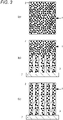
- Fig. 3(a) schematically shows a gel body 1. Black circles in the gel body 1 indicate dispersed ceramic powder 2.
- the produced gel body 1 is frozen at a range of equal to or higher than -40°C and equal to or lower than -10°C.
- the gel body 1 is frozen in such a manner that a bottom surface of the gel body 1 contacts a copper or aluminum freezing plate 7 as shown in Fig. 3(b) and the gel body 1 is, by heat transfer, cooled in a certain direction (an upward direction in Fig. 3(b) ) from the bottom surface to the other side.
- Fig. 3(b) is a sectional view of the gel body 1 cut along an optional section and the section of the gel body 1 in which the ceramic powder 2 is dispersed is shown without hatching for the sake of viewability.
- Fig. 3(c) is also a sectional view of the gel body 1 cut along an optional section as in Fig. 3(b) and the section of the gel body 1 in which the ceramic powder 2 is dispersed is shown without hatching for the sake of viewability.
- hatched portions indicate the ice crystals 3.
- the ceramic powder 2 is unevenly distributed in regions of the gel body 1 other than the ice crystals 3, as shown in Figs. 3(b) and 3(c) .
- the thickness (the dimension in the upper-lower direction in Fig. 3 ) of the gel body 1 shown in Fig. 3 is set to 1.2 ⁇ m to 130 ⁇ m.
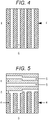
- Fig. 4 is a sectional view of the ceramics sintered body 4 cut along an optional section.
- a sintering method is atmospheric sintering, a heating temperature is 2°C/min to 10°C/min, a sintering temperature is 1300°C to 1500°C, atmosphere is atmospheric air, a pressure is an ordinary pressure, and a sintering time is one hour to four hours.
- blind/continuous holes 5 are formed from a surface of the ceramics sintered body 4 as shown in Fig. 4 , and a porous body in which a wall 6 is formed between adjacent ones of the blind/continuous holes 5 can be formed.
- Fig. 4 shows, as one example, the ceramics sintered body 4 in which only the continuous holes 5 are formed as pores and the wall 6 is formed between adjacent ones of the continuous holes 5.
- the blind/continuous hole indicates a pore formed to appear at a surface of a dental implant body including a ceramics sintered body. Further, the continuous hole indicates, as shown in Fig. 4 , a pore penetrating a dental implant body from a front surface to a back surface as another surface. On the other hand, the blind hole indicates a pore not penetrating a dental implant body to a back surface.
- the dental implant body is formed of the above-described porous body and the blind/continuous holes are formed from the surface, jawbone cell tissues can smoothly enter the blind/continuous holes when the dental implant body is fixed to a jawbone.
- degradation of adhesion of the implant body to jawbone cells can be suppressed without the need for forming a thread at the implant body, and the strength of joint to the jawbone can be improved.
- improvement of the joint strength dropping and detachment of the dental implant body from the jawbone can be reduced, and a prognosis (a progress after dental implant treatment) can be also improved.
- the porosity of the blind/continuous holes is set to 50 ⁇ 10%
- the diameter of the blind/continuous hole is set to equal to or greater than 50 ⁇ m and equal to or smaller than 190 ⁇ m. That is, in the present embodiment, all of the diameters of the blind/continuous holes formed from the surface of the ceramics sintered body are within a range of equal to or greater than 50 ⁇ m and equal to or smaller than 190 ⁇ m.
- the numerical values of the porosity and the diameter are set as described above, and these values are achieved simultaneously in the single porous body.
- the jawbone cell tissues can enter all of the blind/continuous holes.
- the porosity is 50% as a center value, and changes within a range of ⁇ 10%. It has found that if the porosity exceeds 50% + 10% (i.e., 60%), the implant body formed of the porous body does not satisfy a strength for dental use for which resistance to biting force in daily diet and suppression in aging deterioration due to biting are required. On the other hand, it has found that if the porosity is less than 50% - 10% (i.e., 40%), the number of jawbone cell tissues which can enter the blind/continuous holes decreases in association with a decrease in the porosity and adhesion of the implant body to the jawbone cells is degraded.
- the diameter of the blind/continuous hole exceeds 190 ⁇ m, the diameter is too expanded, the growth rate of the jawbone cells in the blind/continuous hole decreases, and the strength of joint between the implant body and the jawbone decreases.
- the diameter of the blind/continuous hole is smaller than 50 ⁇ m, the jawbone cell tissues are difficult to enter the blind/continuous holes, adhesion of the implant body to the jawbone cells is degraded, and the strength of joint between the implant body and the jawbone decreases.
- both of a blind/continuous hole porosity of 50 ⁇ 10% and a blind/continuous hole diameter of equal to or greater than 50 ⁇ m and equal to or smaller than 190 ⁇ m are essential for preventing degradation of adhesion of the dental implant body to the jawbone cells and preventing dropping and detachment of the dental implant body from the jawbone.
- the porosity can be measured by a mercury intrusion technique using a mercury porosimeter. Moreover, the diameter of the blind/continuous hole is measured using a scanning electron microscope (SEM) observation image.
- SEM scanning electron microscope
- the concentration of the ceramic powder dispersed in the gelatable liquid is set to equal to or higher than 5% and equal to or lower than 65% and set a gel body freezing temperature to a range of equal to or higher than -40°C and equal to or lower than -10°C. If either one of the concentration of the ceramic powder 2 or the freezing temperature of the gel body 1 falls outside the concentration or temperature range, both of the porosity and the diameter cannot be set within desired ranges.
- the concentration of the ceramic powder 2 is lower than 5%, the strength of the dental implant body cannot be satisfied due to an extremely-low density of the ceramic molded body. If the concentration exceeds 65%, the ceramic powder is aggregated and easily precipitated, and the stable dispersion state is difficult to be held.
- the gel body freezing temperature reaches lower than -40°C, the entire gel body is frozen before the ice crystals are formed in the frost column shape, and the ceramic powder cannot be unevenly distributed in the gel body regions other than the ice crystals. In addition, if the freezing temperature exceeds -10°C, the ice crystals are difficult to be formed in the gel body.
- the walls 6 are more preferably densely formed in such a manner that the gel body 1 is frozen such that the ice crystals 3 are grown in the certain direction in the gel body 1 as shown in Fig. 3 and the blind/continuous holes 5 are formed in the certain direction as shown in Fig. 4 .
- the term "densely” includes not only a wall with no holes, micropores, or nanopores, but also a wall with a density of equal to or higher than 99%.
- the dense wall is not limited to one with a density of 100% is that in addition to the frost-columnar ice crystals, ice having an extremely-smaller diameter than that of the ice crystal is formed in the walls in the gel body at the above-described freezing step in some cases. Such ice is also sublimed upon drying of the gel body, and therefore, fine holes or pores are formed after sublimation of the ice and holes, micropores, or nanopores are formed in the walls in some cases.
- the certain direction in which the blind/continuous holes are formed indicates one formation direction such as the continuous holes 5 of Fig. 4 formed from the front surface to the back surface (from up to down in Fig. 4 ) of the ceramics sintered body 4.
- the condition necessary for formation of the ice crystals in the certain direction is that the gel body is, by heat transfer, gradually frozen from one location to the other location along the certain direction at a range of equal to or higher than -40°C and equal to or lower than -10°C.
- the surface of the gel body 1 contacting the freezing plate 7 is one location from which freezing is started, and the gel body 1 is, by heat transfer, gradually frozen to the upper surface as the other location along the certain direction (the upward direction in Figs. 3(b) and 3(c) ).
- the direction of formation of the blind/continuous holes is one direction so that the ceramic powder can be unevenly distributed with regularity and the ice crystals can uniformly apply compression force to the entire surfaces of the walls.
- the walls can be more densely formed.
- the dental implant body can be obtained, which has high mechanical properties (mechanical strength and processability) suitable for dental use while having the blind/continuous holes. Consequently, in addition to setting of the porosity and diameter of the blind/continuous holes, the direction of formation of the blind/continuous holes is, for the dental implant body, more preferably set to one direction.
- the blind/continuous holes may be formed in the right-left direction, an oblique direction, or a combination thereof in the ceramics sintered body.
- Fig. 5 shows a variation example where multiple continuous holes 5 are formed from side surfaces in the horizontal direction as viewed in the figure at the upper half of the ceramics sintered body 4 and multiple continuous holes 5 are formed in the vertical direction as viewed in the figure at the lower half as in Fig. 4 .
- Fig. 5 is a sectional view of the ceramics sintered body 4 cut along an optional section. Of the multiple continuous holes 5 formed in the horizontal direction, the lowermost continuous hole 5 communicates with the continuous holes 5 formed in the vertical direction.
- the freezing plate 7 is arranged on the bottom surface to form the continuous holes 5 in the vertical direction, and a freezing agent is arranged on the entire circumference of the side surfaces of the upper half of the gel body to form the multiple continuous holes 5 from the side surfaces to the center of the gel body.
- the continuous holes communicate with each other at shifted positions as in the uppermost and lowermost ones of the multiple continuous holes 5 in the horizontal direction as shown in Fig. 5 .
- the continuous holes communicate with each other at coincident positions as in the continuous hole 5 formed in the middle.
- zirconia is used as the ceramic powder which is a raw material, and therefore, the ceramics sintered body is made of zirconia.
- the zirconia ceramics sintered body is suitable for the dental implant body because such a ceramics sintered body has properties such as chemical durability, thermal resistance, and innoxiousness in terms of health. Further, favorable mechanical properties (mechanical strength and processability) are obtained.
- yttria yttrium oxide: Y 2 O 3
- yttria containing zirconia is more preferred for ensuring higher mechanical strength.
- Specific examples include 2Y zirconia (2 mol% yttria containing zirconia), 2.5Y zirconia (2.5 mol% yttria containing zirconia), 3Y zirconia (3 mol% yttria containing zirconia), and 8Y zirconia (8 mol% yttria containing zirconia).
- the color of the implant body obtained as described above is white, and the Vickers hardness of the implant body is 10 GPa in one direction in which the blind/continuous holes are formed and is 3.5 GPa in other directions.
- the implant body can be formed into a one-piece type or a two-piece type with another abutment (support).
- a dental implant body As aforementioned, gelatable polymeric liquid was prepared, and granulated zirconia powder was dispersed in the liquid at a powder concentration of 35%. Accordingly, slurry was produced.
- polycrystalline zirconia containing no yttria, sintered for two hours at a temperature range of 1350°C to 1450°C, and having a density of 99% was used as a dense body.
- a copper freezing plate 7 contacted a bottom surface of the gel body as in Fig. 3(b) , and the gel body was, by heat transfer, cooled in a certain direction from the bottom surface to the other side and was frozen at -20°C. Accordingly, multiple ice crystals were formed in the certain direction as in Fig. 3(c) .
- the frozen gel body was dried in atmosphere, and the ice crystals were sublimed to obtain a ceramic molded body.
- the ceramic molded body was sintered to form a ceramics sintered body.
- a sintering method was atmospheric sintering, a heating temperature was 2°C/min, a sintering temperature was 1350°C, atmosphere was atmospheric air, a pressure was an ordinary pressure, and a sintering time was two hours.
- Figs. 1 and 2 SEM observation images of the obtained ceramics sintered body are shown in Figs. 1 and 2.
- Fig. 1 shows the observation image in a section perpendicular to the direction of formation of the blind/continuous holes
- Fig. 2 shows the observation image in a section in the direction of formation of the blind/continuous holes. From Fig. 1 , it has confirmed that the blind/continuous holes are formed from a surface of the ceramics sintered body. From Fig. 2 , it has also confirmed that the blind/continuous holes are formed in the certain direction (the upper-lower direction in Fig. 2 ). Moreover, it has also confirmed that a wall density is 99% and walls are densely formed.
Landscapes
- Chemical & Material Sciences (AREA)
- Engineering & Computer Science (AREA)
- Health & Medical Sciences (AREA)
- Ceramic Engineering (AREA)
- Oral & Maxillofacial Surgery (AREA)
- General Health & Medical Sciences (AREA)
- Life Sciences & Earth Sciences (AREA)
- Animal Behavior & Ethology (AREA)
- Public Health (AREA)
- Veterinary Medicine (AREA)
- Epidemiology (AREA)
- Structural Engineering (AREA)
- Dentistry (AREA)
- Manufacturing & Machinery (AREA)
- Materials Engineering (AREA)
- Organic Chemistry (AREA)
- Orthopedic Medicine & Surgery (AREA)
- Mechanical Engineering (AREA)
- Composite Materials (AREA)
- Dispersion Chemistry (AREA)
- Nanotechnology (AREA)
- Plastic & Reconstructive Surgery (AREA)
- Inorganic Chemistry (AREA)
- Dermatology (AREA)
- Medicinal Chemistry (AREA)
- Transplantation (AREA)
- Dental Prosthetics (AREA)
- Dental Preparations (AREA)
- Porous Artificial Stone Or Porous Ceramic Products (AREA)
Abstract
Description
- The present invention relates to a dental implant body and a method for manufacturing the dental implant body.
- For a dental implant body (a tooth root portion; hereinafter merely referred to as an "implant body" as necessary) used for dental implant treatment, not only the strength of the implant body alone but also adherence to jawbone cells for joint between the implant body and a bone are required for resistance to biting force and suppressing in aging deterioration.
- Ceramic has been known as the material of such an implant body. Of ceramic, zirconia (ZrO2) is specifically suitable for the dental implant body because zirconia has properties such as innoxiousness in terms of health in addition to excellent mechanical properties, chemical durability, and thermal resistance.
- As one example of such a zirconia dental implant body,
Patent Literature 1 has been filed as a patent application, for example.Patent Literature 1 is the application relating to an artificial tooth root zirconia implant member made of partially stabilized zirconia containing yttria. - PATENT LITERATURE 1:
JP-A-61-146757 - However, if a screw type (screw-shaped) implant body is produced from zirconia, chipping or cracking is caused at a thread, leading to the probability that the strength of joint to a jawbone decreases and the implant body drops from the jawbone.
- A cylinder type (cylindrical) implant body with no thread is formed with no thread portion, leading to the probability that the implant body is detached from the jawbone.
- The present invention has been made in view of the above-described problems, and an object of the present invention is to provide a dental implant body and a dental implant body manufacturing method capable of improving the strength of joint to a jawbone, reducing dropping and detachment from the jawbone, and improving a prognosis.
- The above-described problems are solved by the following aspects of the present invention. That is, the dental implant body of the present invention is characterized in that the dental implant body includes a ceramics sintered body, and the ceramics sintered body is a porous body having a blind/continuous hole formed from a surface of the ceramics sintered body, and having a wall formed by the blind/continuous hole.
- Moreover, for solving the above-described problems, the dental implant body manufacturing method of the present invention is characterized in that the dental implant body is manufactured in such a manner that ceramic powder is dispersed in gelatable liquid to produce slurry, the slurry is gelated to produce a gel body, the produced gel body is frozen, dried, and sintered to form a porous body including a ceramics sintered body, having a blind/continuous hole formed from a surface of the ceramics sintered body, and having a wall formed by the blind/continuous hole.
- According to the dental implant body and the dental implant body manufacturing method of the present invention, degradation of adherence to jawbone cells can be suppressed, and the strength of joint to a jawbone can be improved. With improvement of the joint strength, dropping and detachment of the dental implant body from the jawbone can be reduced, and a prognosis can be improved.
-
- [
Fig. 1] Fig. 1 shows a SEM observation image of an example of a dental implant body according to the present invention, the observation image showing a section in a direction perpendicular to the direction of formation of blind/continuous holes. - [
Fig. 2] Fig. 2 shows a SEM observation image of the example of the dental implant body according to the present invention, the observation image showing a section in the direction of formation of the blind/continuous holes. - [
Fig. 3] Fig. 3 shows schematic views of the steps of freezing a gel body in the method for manufacturing the dental implant body according to the present invention. - [
Fig. 4] Fig. 4 shows a sectional view schematically showing a ceramics sintered body forming the dental implant body according to the present invention. - [
Fig. 5] Fig. 5 shows a sectional view schematically showing a variation of the ceramics sintered body forming the dental implant body according to the present invention. - A first feature of the present embodiment is a dental implant body including a ceramics sintered body, the ceramics sintered body being a porous body having blind/continuous holes formed from a surface of the ceramics sintered body and walls formed by the blind/continuous holes.
- A second feature of the present embodiment is the dental implant body in which the porosity of the blind/continuous holes is 50 ± 10% and the diameter of the blind/continuous hole is equal to or greater than 50 µm and equal to or smaller than 190 µm.
- A third feature of the present embodiment is the method for manufacturing a dental implant body, the method including producing slurry by dispersing ceramic powder in gelatable liquid, producing a gel body by gelating the slurry, freezing the produced gel body, and drying and sintering the gel body to form a porous body including a ceramics sintered body, having blind/continuous holes formed from a surface of the ceramics sintered body, and having walls formed by the blind/continuous holes, thereby forming the dental implant body.
- A fourth feature of the present embodiment is the method for manufacturing the dental implant, in which the concentration of the ceramic powder dispersed in the gelatable liquid is set to equal to or higher than 5% and equal to or lower than 65%, the gel body is frozen at a range of equal to or higher than -40°C and equal to or lower than -10°C, and the porous body is formed such that the porosity of the blind/continuous holes is 50 ± 10% and the diameter of the blind/continuous hole is equal to or greater than 50 µm and equal to or smaller than 190 µm.
- According to these configuration and manufacturing method, degradation of adherence to jawbone cells can be suppressed or prevented, and the strength of joint to a jawbone can be improved. With improvement of the joint strength, dropping and detachment of the dental implant body from the jawbone can be reduced or prevented, and a prognosis (a progress after dental implant treatment) can be also improved.
- Note that in the present invention, the blind/continuous hole indicates a pore formed to appear at a surface of a dental implant body. Further, the continuous hole indicates a pore penetrating a dental implant body from a front surface to a back surface as another surface. On the other hand, the blind hole indicates a pore not penetrating a dental implant body to aback surface.
- A fifth feature of the present embodiment is the dental implant body in which the ceramics sintered body is made of zirconia.
- A sixth feature of the present embodiment is the method for manufacturing the dental implant body, in which the ceramics sintered body is made of zirconia.
- According to these configuration and manufacturing method, zirconia is used for the ceramics sintered body. Thus, the zirconia ceramics sintered body is suitable for the dental implant body because such a ceramics sintered body has properties such as chemical durability, thermal resistance, and innoxiousness in terms of health. Further, favorable mechanical properties (mechanical strength and processability) are obtained.
- A seventh feature of the present embodiment is the dental implant body in which the blind/continuous holes are formed in a certain direction and the walls are densely formed.
- An eighth feature of the present embodiment is the method for manufacturing the dental implant body, in which ice crystals are grown in a certain direction in the gel body by freezing of the gel body, and accordingly, the blind/continuous holes are formed in the certain direction and the walls are densely formed.
- According to these configuration and manufacturing method, the direction of formation of the blind/continuous holes is one direction, and therefore, the walls can be more densely formed. Thus, the dental implant body can be obtained, which has high mechanical properties suitable for dental use while having the blind/continuous holes.
- Note that in the present invention, the term "densely" includes not only a wall with no holes, micropores, or nanopores, but also a wall with a density of equal to or higher than 99%.
- Hereinafter, the method for manufacturing a dental implant body according to the present embodiment will be described in detail with reference to
Figs. 3 to 5 , and the dental implant body obtained by such a manufacturing method will be described as needed. As the manufacturing method according to the embodiment of the present invention, gelatable polymeric liquid is first prepared, and ceramic powder is dispersed in the liquid at a powder concentration of equal to or higher than 5 % and equal to or lower than 65%. Accordingly, slurry is produced. - The ceramic powder dispersed in the liquid is made of zirconia (ZrO2) and is granulated, and the average particle size of the ceramic powder is set to a range of 0.01 µm (10 nm) to 0.08 µm (80 nm). If the average particle size is smaller than 0.01 µm, it is not preferred because the ceramic powder is difficult to be handled and workability is degraded. On the other hand, if the average particle size exceeds 0.08 µm, it is not preferred because the ceramic powder is easily precipitated in the slurry and the slurry cannot be stably obtained.
- The water content of the slurry is set to 35 wt% to 95 wt%. If the water content is lower than 35 wt%, the ceramic powder is aggregated and easily precipitated and a stable dispersion state is difficult to be held. On the other hand, if the water content exceeds 95 wt%, the density of a ceramic molded body after water has been sublimed into ice crystals is extremely low and the ceramic molded body cannot satisfy a strength as the dental implant body.
- Next, the produced slurry is gelated, and a gel body is produced. Gelation indicates that the slurry in which the ceramic powder is dispersed is solidified, and the gel body is formed with a cylindrical outer shape.
Fig. 3(a) schematically shows agel body 1. Black circles in thegel body 1 indicate dispersedceramic powder 2. - Next, the produced
gel body 1 is frozen at a range of equal to or higher than -40°C and equal to or lower than -10°C. Thegel body 1 is frozen in such a manner that a bottom surface of thegel body 1 contacts a copper or aluminumfreezing plate 7 as shown inFig. 3(b) and thegel body 1 is, by heat transfer, cooled in a certain direction (an upward direction inFig. 3(b) ) from the bottom surface to the other side. Note thatFig. 3(b) is a sectional view of thegel body 1 cut along an optional section and the section of thegel body 1 in which theceramic powder 2 is dispersed is shown without hatching for the sake of viewability. - Since the
gel body 1 is frozen in the certain direction from the bottom surface contacting thefreezing plate 7,multiple ice crystals 3 frozen in a frost column shape from water without theceramic powder 2 being dispersed are formed in the certain direction in thegel body 1 as shown fromFig. 3(b) to Fig. 3(c) . Note thatFig. 3(c) is also a sectional view of thegel body 1 cut along an optional section as inFig. 3(b) and the section of thegel body 1 in which theceramic powder 2 is dispersed is shown without hatching for the sake of viewability. InFigs. 3(b) and 3(c) , hatched portions indicate theice crystals 3. - Meanwhile, the
ceramic powder 2 is unevenly distributed in regions of thegel body 1 other than theice crystals 3, as shown inFigs. 3(b) and 3(c) . Water expands due to freezing, and for this reason, the regions in which the ceramic powder is unevenly distributed are pushed and compressed by theice crystals 3. Due to such compression, the regions in which the ceramic powder is unevenly distributed are densified, and later-described walls are formed accordingly. Note that the thickness (the dimension in the upper-lower direction inFig. 3 ) of thegel body 1 shown inFig. 3 is set to 1.2 µm to 130 µm. - Next, the frozen gel body is dried in atmosphere, and the
ice crystals 3 are sublimed to obtain a ceramic molded body. Thereafter, the ceramic molded body is sintered to form a ceramics sinteredbody 4 shown inFig. 4 . Note thatFig. 4 is a sectional view of the ceramics sinteredbody 4 cut along an optional section. A sintering method is atmospheric sintering, a heating temperature is 2°C/min to 10°C/min, a sintering temperature is 1300°C to 1500°C, atmosphere is atmospheric air, a pressure is an ordinary pressure, and a sintering time is one hour to four hours. - The
ice crystals 3 are sublimed as described above, and are sintered thereafter. Accordingly, blind/continuous holes 5 are formed from a surface of the ceramics sinteredbody 4 as shown inFig. 4 , and a porous body in which awall 6 is formed between adjacent ones of the blind/continuous holes 5 can be formed.Fig. 4 shows, as one example, the ceramics sinteredbody 4 in which only thecontinuous holes 5 are formed as pores and thewall 6 is formed between adjacent ones of thecontinuous holes 5. - The blind/continuous hole indicates a pore formed to appear at a surface of a dental implant body including a ceramics sintered body. Further, the continuous hole indicates, as shown in
Fig. 4 , a pore penetrating a dental implant body from a front surface to a back surface as another surface. On the other hand, the blind hole indicates a pore not penetrating a dental implant body to a back surface. - Since the dental implant body is formed of the above-described porous body and the blind/continuous holes are formed from the surface, jawbone cell tissues can smoothly enter the blind/continuous holes when the dental implant body is fixed to a jawbone. Thus, degradation of adhesion of the implant body to jawbone cells can be suppressed without the need for forming a thread at the implant body, and the strength of joint to the jawbone can be improved. With improvement of the joint strength, dropping and detachment of the dental implant body from the jawbone can be reduced, and a prognosis (a progress after dental implant treatment) can be also improved. Moreover, there are no concerns about chipping and cracking due to thread formation.
- Further, in the present embodiment, the porosity of the blind/continuous holes is set to 50 ± 10%, and the diameter of the blind/continuous hole is set to equal to or greater than 50 µm and equal to or smaller than 190 µm. That is, in the present embodiment, all of the diameters of the blind/continuous holes formed from the surface of the ceramics sintered body are within a range of equal to or greater than 50 µm and equal to or smaller than 190 µm. The numerical values of the porosity and the diameter are set as described above, and these values are achieved simultaneously in the single porous body. Thus, the jawbone cell tissues can enter all of the blind/continuous holes. Consequently, degradation of adhesion of the implant body to the jawbone cells can be prevented without the need for forming the thread at the implant body, and the strength of joint to the jawbone can be further improved. With further improvement of the joint strength, dropping and detachment of the dental implant body from the jawbone can be prevented, and the prognosis can be also improved.
- The porosity is 50% as a center value, and changes within a range of ±10%. It has found that if the porosity exceeds 50% + 10% (i.e., 60%), the implant body formed of the porous body does not satisfy a strength for dental use for which resistance to biting force in daily diet and suppression in aging deterioration due to biting are required. On the other hand, it has found that if the porosity is less than 50% - 10% (i.e., 40%), the number of jawbone cell tissues which can enter the blind/continuous holes decreases in association with a decrease in the porosity and adhesion of the implant body to the jawbone cells is degraded.
- Further, it has found that if the diameter of the blind/continuous hole exceeds 190 µm, the diameter is too expanded, the growth rate of the jawbone cells in the blind/continuous hole decreases, and the strength of joint between the implant body and the jawbone decreases. On the other hand, it has found that if the diameter of the blind/continuous hole is smaller than 50 µm, the jawbone cell tissues are difficult to enter the blind/continuous holes, adhesion of the implant body to the jawbone cells is degraded, and the strength of joint between the implant body and the jawbone decreases.
- As described above, it has confirmed that in the dental implant body formed of the porous body, both of a blind/continuous hole porosity of 50 ± 10% and a blind/continuous hole diameter of equal to or greater than 50 µm and equal to or smaller than 190 µm are essential for preventing degradation of adhesion of the dental implant body to the jawbone cells and preventing dropping and detachment of the dental implant body from the jawbone.
- The porosity can be measured by a mercury intrusion technique using a mercury porosimeter. Moreover, the diameter of the blind/continuous hole is measured using a scanning electron microscope (SEM) observation image.
- In the present embodiment, it has found that as the conditions for achieving both of a blind/continuous hole porosity of 50 ± 10% and a blind/continuous hole diameter of equal to or greater than 50 µm and equal to or smaller than 190 µm, it is essential to set the concentration of the ceramic powder dispersed in the gelatable liquid to equal to or higher than 5% and equal to or lower than 65% and set a gel body freezing temperature to a range of equal to or higher than -40°C and equal to or lower than -10°C. If either one of the concentration of the
ceramic powder 2 or the freezing temperature of thegel body 1 falls outside the concentration or temperature range, both of the porosity and the diameter cannot be set within desired ranges. - Further, if the concentration of the
ceramic powder 2 is lower than 5%, the strength of the dental implant body cannot be satisfied due to an extremely-low density of the ceramic molded body. If the concentration exceeds 65%, the ceramic powder is aggregated and easily precipitated, and the stable dispersion state is difficult to be held. - If the gel body freezing temperature reaches lower than -40°C, the entire gel body is frozen before the ice crystals are formed in the frost column shape, and the ceramic powder cannot be unevenly distributed in the gel body regions other than the ice crystals. In addition, if the freezing temperature exceeds -10°C, the ice crystals are difficult to be formed in the gel body.
- Further, in the present embodiment, according to the porous body used for the dental implant body and the method for manufacturing such a porous body, the
walls 6 are more preferably densely formed in such a manner that thegel body 1 is frozen such that theice crystals 3 are grown in the certain direction in thegel body 1 as shown inFig. 3 and the blind/continuous holes 5 are formed in the certain direction as shown inFig. 4 . The term "densely" includes not only a wall with no holes, micropores, or nanopores, but also a wall with a density of equal to or higher than 99%. A reason why the dense wall is not limited to one with a density of 100% is that in addition to the frost-columnar ice crystals, ice having an extremely-smaller diameter than that of the ice crystal is formed in the walls in the gel body at the above-described freezing step in some cases. Such ice is also sublimed upon drying of the gel body, and therefore, fine holes or pores are formed after sublimation of the ice and holes, micropores, or nanopores are formed in the walls in some cases. - Note that the certain direction in which the blind/continuous holes are formed indicates one formation direction such as the
continuous holes 5 ofFig. 4 formed from the front surface to the back surface (from up to down inFig. 4 ) of the ceramics sinteredbody 4. - It is necessary for formation of the blind/continuous holes in the certain direction to form the ice crystals in the certain direction in the gel body. As a result of study conducted by the applicant of the present application, the condition necessary for formation of the ice crystals in the certain direction is that the gel body is, by heat transfer, gradually frozen from one location to the other location along the certain direction at a range of equal to or higher than -40°C and equal to or lower than -10°C.
- In
Figs. 3(b) and 3(c) , the surface of thegel body 1 contacting the freezingplate 7 is one location from which freezing is started, and thegel body 1 is, by heat transfer, gradually frozen to the upper surface as the other location along the certain direction (the upward direction inFigs. 3(b) and 3(c) ). - The direction of formation of the blind/continuous holes is one direction so that the ceramic powder can be unevenly distributed with regularity and the ice crystals can uniformly apply compression force to the entire surfaces of the walls. Thus, the walls can be more densely formed. Thus, the dental implant body can be obtained, which has high mechanical properties (mechanical strength and processability) suitable for dental use while having the blind/continuous holes. Consequently, in addition to setting of the porosity and diameter of the blind/continuous holes, the direction of formation of the blind/continuous holes is, for the dental implant body, more preferably set to one direction.
- The blind/continuous holes may be formed in the right-left direction, an oblique direction, or a combination thereof in the ceramics sintered body.
Fig. 5 shows a variation example where multiplecontinuous holes 5 are formed from side surfaces in the horizontal direction as viewed in the figure at the upper half of the ceramics sinteredbody 4 and multiplecontinuous holes 5 are formed in the vertical direction as viewed in the figure at the lower half as inFig. 4 . Note thatFig. 5 is a sectional view of the ceramics sinteredbody 4 cut along an optional section. Of the multiplecontinuous holes 5 formed in the horizontal direction, the lowermostcontinuous hole 5 communicates with thecontinuous holes 5 formed in the vertical direction. - For the ceramics sintered
body 4 ofFig. 5 , the freezingplate 7 is arranged on the bottom surface to form thecontinuous holes 5 in the vertical direction, and a freezing agent is arranged on the entire circumference of the side surfaces of the upper half of the gel body to form the multiplecontinuous holes 5 from the side surfaces to the center of the gel body. Thus, in some cases, the continuous holes communicate with each other at shifted positions as in the uppermost and lowermost ones of the multiplecontinuous holes 5 in the horizontal direction as shown inFig. 5 . In other cases, the continuous holes communicate with each other at coincident positions as in thecontinuous hole 5 formed in the middle. - Further, in the present embodiment, zirconia is used as the ceramic powder which is a raw material, and therefore, the ceramics sintered body is made of zirconia. The zirconia ceramics sintered body is suitable for the dental implant body because such a ceramics sintered body has properties such as chemical durability, thermal resistance, and innoxiousness in terms of health. Further, favorable mechanical properties (mechanical strength and processability) are obtained.
- Considering application of zirconia to the dental implant body as a biological reinforcement member, yttria (yttrium oxide: Y2O3) containing zirconia is more preferred for ensuring higher mechanical strength. Specific examples include 2Y zirconia (2 mol% yttria containing zirconia), 2.5Y zirconia (2.5 mol% yttria containing zirconia), 3Y zirconia (3 mol% yttria containing zirconia), and 8Y zirconia (8 mol% yttria containing zirconia).
- The color of the implant body obtained as described above is white, and the Vickers hardness of the implant body is 10 GPa in one direction in which the blind/continuous holes are formed and is 3.5 GPa in other directions. The implant body can be formed into a one-piece type or a two-piece type with another abutment (support).
- An example according to the present invention will be described below, but the present invention is not limited only to the following example.
- Hereinafter, the method for manufacturing a dental implant body according to the present example will be described. First, gelatable polymeric liquid was prepared, and granulated zirconia powder was dispersed in the liquid at a powder concentration of 35%. Accordingly, slurry was produced. In the present example, polycrystalline zirconia containing no yttria, sintered for two hours at a temperature range of 1350°C to 1450°C, and having a density of 99% was used as a dense body.
- Next, the produced slurry was gelated, and a gel body was produced. A
copper freezing plate 7 contacted a bottom surface of the gel body as inFig. 3(b) , and the gel body was, by heat transfer, cooled in a certain direction from the bottom surface to the other side and was frozen at -20°C. Accordingly, multiple ice crystals were formed in the certain direction as inFig. 3(c) . - Next, the frozen gel body was dried in atmosphere, and the ice crystals were sublimed to obtain a ceramic molded body. The ceramic molded body was sintered to form a ceramics sintered body. A sintering method was atmospheric sintering, a heating temperature was 2°C/min, a sintering temperature was 1350°C, atmosphere was atmospheric air, a pressure was an ordinary pressure, and a sintering time was two hours.
- SEM observation images of the obtained ceramics sintered body are shown in
Figs. 1 and 2. Fig. 1 shows the observation image in a section perpendicular to the direction of formation of the blind/continuous holes, andFig. 2 shows the observation image in a section in the direction of formation of the blind/continuous holes. FromFig. 1 , it has confirmed that the blind/continuous holes are formed from a surface of the ceramics sintered body. FromFig. 2 , it has also confirmed that the blind/continuous holes are formed in the certain direction (the upper-lower direction inFig. 2 ). Moreover, it has also confirmed that a wall density is 99% and walls are densely formed. - As a result of measurement of the porosity of the blind/continuous holes of the ceramics sintered body by a mercury intrusion technique using a mercury porosimeter, it has found that the porosity is 60%. As a result of observation of the diameter of the blind/continuous hole by means of the SEM observation images, it has also found that all diameters observed at multiple random locations of the SEM observation images are within a range of equal to or greater than 50 µm and equal to or smaller than 190 µm.
- Jawbone cell tissues of subjects randomly selected in terms of sex and age adhered to a surface of the ceramics sintered body, and entrance into the blind/continuous holes was observed. Further, it has confirmed that the jawbone cell tissues having entered the blind/continuous holes are held adhered to the surface of the ceramics sintered body without detachment.
-
- 1
- Gel Body
- 2
- Ceramic Powder
- 3
- Ice Crystal
- 4
- Ceramics Sintered Body
- 5
- Through-Hole
- 6
- Wall
- 7
- Freezing Plate
Claims (8)
- A dental implant body comprising:a ceramics sintered body,wherein the ceramics sintered body is a porous body having a blind/continuous hole formed from a surface of the ceramics sintered body and a wall formed by the blind/continuous hole.
- The dental implant body according to claim 1, whereina porosity of the blind/continuous hole is 50 ± 10%, anda diameter of the blind/continuous hole is equal to or greater than 50 µm and equal to or smaller than 190 µm.
- The dental implant body according to claim 1 or 2, wherein
the ceramics sintered body is made of zirconia. - The dental implant body according to any one of claims 1 to 3, wherein
the blind/continuous hole is formed in a certain direction, and the wall is densely formed. - A method for manufacturing a dental implant body, comprising:producing slurry by dispersing ceramic powder in gelatable liquid;producing a gel body by gelating the slurry;freezing the produced gel body; anddrying and sintering the gel body to form a porous body including a ceramics sintered body, having a blind/continuous hole formed from a surface of the ceramics sintered body, and having a wall formed by the blind/continuous hole, thereby forming the dental implant body.
- The method for manufacturing the dental implant body according to claim 5, whereina concentration of the ceramic powder dispersed in the gelatable liquid is set to equal to or higher than 5% and equal to or lower than 65%,the gel body is frozen at a range of equal to or higher than -40°C and equal to or lower than -10°C, andthe porous body is formed such that a porosity of the blind/continuous hole is 50 ± 10% and a diameter of the blind/continuous hole is equal to or greater than 50 µm and equal to or smaller than 190 µm.
- The method for manufacturing the dental implant body according to claim 5 or 6, wherein
the ceramics sintered body is made of zirconia. - The method for manufacturing the dental implant body according to any one of claims 5 to 7, wherein
an ice crystal is grown in a certain direction in the gel body by freezing of the gel body, and accordingly, the blind/continuous hole is formed in the certain direction and the wall is densely formed.
Applications Claiming Priority (2)
| Application Number | Priority Date | Filing Date | Title |
|---|---|---|---|
| JP2019132817A JP7455302B2 (en) | 2019-07-18 | 2019-07-18 | Dental implant body and method for manufacturing dental implant body |
| PCT/JP2020/027661 WO2021010435A1 (en) | 2019-07-18 | 2020-07-16 | Dental implant body and dental implant body manufacturing method |
Publications (4)
| Publication Number | Publication Date |
|---|---|
| EP4000556A1 true EP4000556A1 (en) | 2022-05-25 |
| EP4000556A4 EP4000556A4 (en) | 2023-08-02 |
| EP4000556B1 EP4000556B1 (en) | 2025-10-15 |
| EP4000556B8 EP4000556B8 (en) | 2025-11-26 |
Family
ID=74209894
Family Applications (1)
| Application Number | Title | Priority Date | Filing Date |
|---|---|---|---|
| EP20841277.5A Active EP4000556B8 (en) | 2019-07-18 | 2020-07-16 | Dental implant body and dental implant body manufacturing method |
Country Status (5)
| Country | Link |
|---|---|
| US (1) | US20220125557A1 (en) |
| EP (1) | EP4000556B8 (en) |
| JP (1) | JP7455302B2 (en) |
| CN (1) | CN114126536A (en) |
| WO (1) | WO2021010435A1 (en) |
Families Citing this family (1)
| Publication number | Priority date | Publication date | Assignee | Title |
|---|---|---|---|---|
| JP7465570B2 (en) * | 2022-04-10 | 2024-04-11 | 合同会社Medical EMW systems | Bone conduction hearing aids |
Family Cites Families (17)
| Publication number | Priority date | Publication date | Assignee | Title |
|---|---|---|---|---|
| JP3400740B2 (en) * | 1999-04-13 | 2003-04-28 | 東芝セラミックス株式会社 | Calcium phosphate porous sintered body and method for producing the same |
| EP1671662A4 (en) * | 2003-08-27 | 2010-12-15 | Makoto Ogiso | Structural body constituted of biocompatible material impregnated with fine bone dust and process for producing the same |
| US8814567B2 (en) * | 2005-05-26 | 2014-08-26 | Zimmer Dental, Inc. | Dental implant prosthetic device with improved osseointegration and esthetic features |
| JP2009516544A (en) * | 2005-11-18 | 2009-04-23 | セラマテック・インク | Porous load-bearing ceramic or metal implant |
| WO2007148788A1 (en) * | 2006-06-23 | 2007-12-27 | Kuraray Co., Ltd. | Porous ceramic material and method of producing the same |
| JP5176198B2 (en) * | 2007-02-21 | 2013-04-03 | 独立行政法人産業技術総合研究所 | Method for producing ceramic porous body having macroporous communication holes |
| US9744043B2 (en) * | 2007-07-16 | 2017-08-29 | Lifenet Health | Crafting of cartilage |
| JP4321637B2 (en) * | 2007-07-27 | 2009-08-26 | セイコーエプソン株式会社 | Method for producing dental implant |
| US20090098510A1 (en) * | 2007-10-16 | 2009-04-16 | Kai Zhang | Dental implant and prosthetic device preparation kit |
| WO2009072788A1 (en) * | 2007-12-03 | 2009-06-11 | Boo Rak Lee | A implant consisting of ball and manufacturing method thereof |
| JP5045943B2 (en) * | 2008-07-09 | 2012-10-10 | 国立大学法人京都大学 | Method for producing porous ceramic material |
| US9782518B2 (en) * | 2010-11-25 | 2017-10-10 | Kuraray Co., Ltd. | Method for producing implant material |
| FR2999193B1 (en) * | 2012-12-07 | 2017-07-28 | Saint-Gobain Centre De Rech Et D'Etudes Europeen | PRODUCT WITH ORIENTED FUNCTION. |
| WO2015168332A2 (en) * | 2014-04-30 | 2015-11-05 | Osseodyne Surgical Solutions, Llc | Osseointegrative surgical implant |
| KR101607655B1 (en) * | 2014-07-10 | 2016-03-31 | 고려대학교 산학협력단 | Macro / micro duplex tool shaping method for manufacturing a three-dimensional porous support and macro / micro duplex tool shaping three-dimensional porous support |
| FR3048354B1 (en) * | 2016-03-04 | 2021-12-10 | Michael Sadoun | PREFORM INTENDED FOR THE MANUFACTURE OF A DENTAL PROSTHESIS |
| JP6963966B2 (en) * | 2017-10-23 | 2021-11-10 | 株式会社クラレ | Porous ceramic material and its manufacturing method |
-
2019
- 2019-07-18 JP JP2019132817A patent/JP7455302B2/en active Active
-
2020
- 2020-07-16 WO PCT/JP2020/027661 patent/WO2021010435A1/en not_active Ceased
- 2020-07-16 CN CN202080051230.4A patent/CN114126536A/en active Pending
- 2020-07-16 EP EP20841277.5A patent/EP4000556B8/en active Active
-
2022
- 2022-01-10 US US17/647,550 patent/US20220125557A1/en active Pending
Also Published As
| Publication number | Publication date |
|---|---|
| EP4000556B1 (en) | 2025-10-15 |
| JP2021016477A (en) | 2021-02-15 |
| CN114126536A (en) | 2022-03-01 |
| US20220125557A1 (en) | 2022-04-28 |
| JP7455302B2 (en) | 2024-03-26 |
| EP4000556B8 (en) | 2025-11-26 |
| WO2021010435A1 (en) | 2021-01-21 |
| EP4000556A4 (en) | 2023-08-02 |
Similar Documents
| Publication | Publication Date | Title |
|---|---|---|
| US4983182A (en) | Ceramic implant and process for its production | |
| US7148167B2 (en) | Alumina/zirconia ceramics and method of producing the same | |
| CN102939274B (en) | Microreactor comprising porous ceramic material | |
| KR100547527B1 (en) | Hydrogen Permeable Structure and Manufacturing Method Thereof | |
| US20130307176A1 (en) | Single-Fire Two-Step Soak Method | |
| CN103562155A (en) | Method for controlling properties of aluminum titanate ceramic filters | |
| EP4000556B1 (en) | Dental implant body and dental implant body manufacturing method | |
| US7399722B2 (en) | Alumina/zirconia ceramics and method of producing the same | |
| KR20090105234A (en) | Tubular hydrogen separator and its manufacturing method | |
| US9237955B2 (en) | Intervertebral disc endoprosthesis | |
| EP0667322B1 (en) | Light-permeable ceramic material and method of manufacturing the same | |
| US7687138B2 (en) | Porous calcium phosphate ceramic and method for producing same | |
| US20020043735A1 (en) | Method for producing a silicon nitride filter | |
| EP3587376A1 (en) | High-purity calcium carbonate sintered body and production method thereof, and high-purity calcium carbonate porous sintered body and production method thereof | |
| US6821916B2 (en) | Ceramics for in vivo use | |
| JP2004275202A (en) | Porous ceramic implant material and method for producing the same | |
| JPH0859367A (en) | Preparation of porous ceramic or porous ceramic laminated body by using hollow spherical polymeric precursor | |
| Liou et al. | Crystallographic facetting in sintered barium titanate | |
| WO2023013551A1 (en) | Calcium carbonate raw material for sintered body, porous calcium carbonate sintered body, compact calcium carbonate sintered body, and methods for producing these | |
| EP3328452B1 (en) | Metallic and/or ceramic components with at least one osseointegrative and osteoinductive surface (multi)layer structure | |
| EP0607017A1 (en) | Composite biotic implant and method of making a composite biotic implant | |
| JPH08208317A (en) | Alumina sintered body and method for producing the same | |
| EP3943467A1 (en) | Calcium carbonate sintered body and method for producing same, and bone grafting material | |
| JPH07249414A (en) | Solid oxide fuel cell | |
| JP2006122634A (en) | Biomaterial, artificial joint using the same, and method for producing biomaterial |
Legal Events
| Date | Code | Title | Description |
|---|---|---|---|
| STAA | Information on the status of an ep patent application or granted ep patent |
Free format text: STATUS: THE INTERNATIONAL PUBLICATION HAS BEEN MADE |
|
| PUAI | Public reference made under article 153(3) epc to a published international application that has entered the european phase |
Free format text: ORIGINAL CODE: 0009012 |
|
| STAA | Information on the status of an ep patent application or granted ep patent |
Free format text: STATUS: REQUEST FOR EXAMINATION WAS MADE |
|
| 17P | Request for examination filed |
Effective date: 20220210 |
|
| AK | Designated contracting states |
Kind code of ref document: A1 Designated state(s): AL AT BE BG CH CY CZ DE DK EE ES FI FR GB GR HR HU IE IS IT LI LT LU LV MC MK MT NL NO PL PT RO RS SE SI SK SM TR |
|
| DAV | Request for validation of the european patent (deleted) | ||
| DAX | Request for extension of the european patent (deleted) | ||
| RAP3 | Party data changed (applicant data changed or rights of an application transferred) |
Owner name: NATIONAL INSTITUTE OF ADVANCED INDUSTRIAL SCIENCE AND TECHNOLOGY Owner name: ORBRAY CO., LTD. |
|
| A4 | Supplementary search report drawn up and despatched |
Effective date: 20230705 |
|
| RIC1 | Information provided on ipc code assigned before grant |
Ipc: A61K 6/84 20200101ALI20230629BHEP Ipc: C04B 35/486 20060101ALI20230629BHEP Ipc: A61C 8/00 20060101AFI20230629BHEP |
|
| STAA | Information on the status of an ep patent application or granted ep patent |
Free format text: STATUS: EXAMINATION IS IN PROGRESS |
|
| 17Q | First examination report despatched |
Effective date: 20240319 |
|
| GRAP | Despatch of communication of intention to grant a patent |
Free format text: ORIGINAL CODE: EPIDOSNIGR1 |
|
| STAA | Information on the status of an ep patent application or granted ep patent |
Free format text: STATUS: GRANT OF PATENT IS INTENDED |
|
| INTG | Intention to grant announced |
Effective date: 20250519 |
|
| GRAS | Grant fee paid |
Free format text: ORIGINAL CODE: EPIDOSNIGR3 |
|
| GRAA | (expected) grant |
Free format text: ORIGINAL CODE: 0009210 |
|
| STAA | Information on the status of an ep patent application or granted ep patent |
Free format text: STATUS: THE PATENT HAS BEEN GRANTED |
|
| AK | Designated contracting states |
Kind code of ref document: B1 Designated state(s): AL AT BE BG CH CY CZ DE DK EE ES FI FR GB GR HR HU IE IS IT LI LT LU LV MC MK MT NL NO PL PT RO RS SE SI SK SM TR |
|
| REG | Reference to a national code |
Ref country code: GB Ref legal event code: FG4D Ref country code: CH Ref legal event code: F10 Free format text: ST27 STATUS EVENT CODE: U-0-0-F10-F00 (AS PROVIDED BY THE NATIONAL OFFICE) Effective date: 20251015 |
|
| REG | Reference to a national code |
Ref country code: CH Ref legal event code: Q17 Free format text: ST27 STATUS EVENT CODE: U-0-0-Q10-Q17 (AS PROVIDED BY THE NATIONAL OFFICE) Effective date: 20251029 Ref country code: CH Ref legal event code: W10 Free format text: ST27 STATUS EVENT CODE: U-0-0-W10-W00 (AS PROVIDED BY THE NATIONAL OFFICE) Effective date: 20251029 |
|
| REG | Reference to a national code |
Ref country code: DE Ref legal event code: R081 Ref document number: 602020060630 Country of ref document: DE Owner name: ORBRAY CO., LTD., JP Free format text: FORMER OWNERS: NATIONAL INSTITUTE OF ADVANCED INDUSTRIAL SCIENCE AND TECHNOLOGY, TOKYO, JP; ORBRAY CO., LTD., TOKYO, JP |
|
| REG | Reference to a national code |
Ref country code: IE Ref legal event code: FG4D |
|
| REG | Reference to a national code |
Ref country code: DE Ref legal event code: R096 Ref document number: 602020060630 Country of ref document: DE |
|
| RAP2 | Party data changed (patent owner data changed or rights of a patent transferred) |
Owner name: ORBRAY CO., LTD. |
|
| REG | Reference to a national code |
Ref country code: CH Ref legal event code: R17 Free format text: ST27 STATUS EVENT CODE: U-0-0-R10-R17 (AS PROVIDED BY THE NATIONAL OFFICE) Effective date: 20251204 |
|
| REG | Reference to a national code |
Ref country code: SE Ref legal event code: TRGR |
|
| P01 | Opt-out of the competence of the unified patent court (upc) registered |
Free format text: CASE NUMBER: UPC_APP_0015722_4000556/2025 Effective date: 20251204 |
|
| REG | Reference to a national code |
Ref country code: NL Ref legal event code: MP Effective date: 20251015 |
|
| REG | Reference to a national code |
Ref country code: AT Ref legal event code: MK05 Ref document number: 1846272 Country of ref document: AT Kind code of ref document: T Effective date: 20251015 |
|
| PG25 | Lapsed in a contracting state [announced via postgrant information from national office to epo] |
Ref country code: NL Free format text: LAPSE BECAUSE OF FAILURE TO SUBMIT A TRANSLATION OF THE DESCRIPTION OR TO PAY THE FEE WITHIN THE PRESCRIBED TIME-LIMIT Effective date: 20251015 |
|
| PG25 | Lapsed in a contracting state [announced via postgrant information from national office to epo] |
Ref country code: ES Free format text: LAPSE BECAUSE OF FAILURE TO SUBMIT A TRANSLATION OF THE DESCRIPTION OR TO PAY THE FEE WITHIN THE PRESCRIBED TIME-LIMIT Effective date: 20251015 |
|
| REG | Reference to a national code |
Ref country code: LT Ref legal event code: MG9D |
|
| PG25 | Lapsed in a contracting state [announced via postgrant information from national office to epo] |
Ref country code: NO Free format text: LAPSE BECAUSE OF FAILURE TO SUBMIT A TRANSLATION OF THE DESCRIPTION OR TO PAY THE FEE WITHIN THE PRESCRIBED TIME-LIMIT Effective date: 20260115 |
|
| PG25 | Lapsed in a contracting state [announced via postgrant information from national office to epo] |
Ref country code: AT Free format text: LAPSE BECAUSE OF FAILURE TO SUBMIT A TRANSLATION OF THE DESCRIPTION OR TO PAY THE FEE WITHIN THE PRESCRIBED TIME-LIMIT Effective date: 20251015 Ref country code: HR Free format text: LAPSE BECAUSE OF FAILURE TO SUBMIT A TRANSLATION OF THE DESCRIPTION OR TO PAY THE FEE WITHIN THE PRESCRIBED TIME-LIMIT Effective date: 20251015 Ref country code: FI Free format text: LAPSE BECAUSE OF FAILURE TO SUBMIT A TRANSLATION OF THE DESCRIPTION OR TO PAY THE FEE WITHIN THE PRESCRIBED TIME-LIMIT Effective date: 20251015 |
|
| PG25 | Lapsed in a contracting state [announced via postgrant information from national office to epo] |
Ref country code: RS Free format text: LAPSE BECAUSE OF FAILURE TO SUBMIT A TRANSLATION OF THE DESCRIPTION OR TO PAY THE FEE WITHIN THE PRESCRIBED TIME-LIMIT Effective date: 20260115 |
|
| PG25 | Lapsed in a contracting state [announced via postgrant information from national office to epo] |
Ref country code: IS Free format text: LAPSE BECAUSE OF FAILURE TO SUBMIT A TRANSLATION OF THE DESCRIPTION OR TO PAY THE FEE WITHIN THE PRESCRIBED TIME-LIMIT Effective date: 20260215 |
|
| PG25 | Lapsed in a contracting state [announced via postgrant information from national office to epo] |
Ref country code: PT Free format text: LAPSE BECAUSE OF FAILURE TO SUBMIT A TRANSLATION OF THE DESCRIPTION OR TO PAY THE FEE WITHIN THE PRESCRIBED TIME-LIMIT Effective date: 20260216 |
|
| PG25 | Lapsed in a contracting state [announced via postgrant information from national office to epo] |
Ref country code: PL Free format text: LAPSE BECAUSE OF FAILURE TO SUBMIT A TRANSLATION OF THE DESCRIPTION OR TO PAY THE FEE WITHIN THE PRESCRIBED TIME-LIMIT Effective date: 20251015 |
|
| PG25 | Lapsed in a contracting state [announced via postgrant information from national office to epo] |
Ref country code: LV Free format text: LAPSE BECAUSE OF FAILURE TO SUBMIT A TRANSLATION OF THE DESCRIPTION OR TO PAY THE FEE WITHIN THE PRESCRIBED TIME-LIMIT Effective date: 20251015 |
|
| PG25 | Lapsed in a contracting state [announced via postgrant information from national office to epo] |
Ref country code: BG Free format text: LAPSE BECAUSE OF FAILURE TO SUBMIT A TRANSLATION OF THE DESCRIPTION OR TO PAY THE FEE WITHIN THE PRESCRIBED TIME-LIMIT Effective date: 20251015 |