EP4000544A1 - Surgical access device with fixation mechanism - Google Patents
Surgical access device with fixation mechanism Download PDFInfo
- Publication number
- EP4000544A1 EP4000544A1 EP21209207.6A EP21209207A EP4000544A1 EP 4000544 A1 EP4000544 A1 EP 4000544A1 EP 21209207 A EP21209207 A EP 21209207A EP 4000544 A1 EP4000544 A1 EP 4000544A1
- Authority
- EP
- European Patent Office
- Prior art keywords
- wing
- magnet
- elongated portion
- cannula body
- magnets
- Prior art date
- Legal status (The legal status is an assumption and is not a legal conclusion. Google has not performed a legal analysis and makes no representation as to the accuracy of the status listed.)
- Withdrawn
Links
Images





Classifications
-
- A—HUMAN NECESSITIES
- A61—MEDICAL OR VETERINARY SCIENCE; HYGIENE
- A61B—DIAGNOSIS; SURGERY; IDENTIFICATION
- A61B17/00—Surgical instruments, devices or methods
- A61B17/34—Trocars; Puncturing needles
- A61B17/3417—Details of tips or shafts, e.g. grooves, expandable, bendable; Multiple coaxial sliding cannulas, e.g. for dilating
- A61B17/3421—Cannulas
-
- A—HUMAN NECESSITIES
- A61—MEDICAL OR VETERINARY SCIENCE; HYGIENE
- A61B—DIAGNOSIS; SURGERY; IDENTIFICATION
- A61B17/00—Surgical instruments, devices or methods
- A61B17/34—Trocars; Puncturing needles
- A61B17/3417—Details of tips or shafts, e.g. grooves, expandable, bendable; Multiple coaxial sliding cannulas, e.g. for dilating
- A61B17/3421—Cannulas
- A61B17/3423—Access ports, e.g. toroid shape introducers for instruments or hands
-
- A—HUMAN NECESSITIES
- A61—MEDICAL OR VETERINARY SCIENCE; HYGIENE
- A61B—DIAGNOSIS; SURGERY; IDENTIFICATION
- A61B17/00—Surgical instruments, devices or methods
- A61B2017/00831—Material properties
- A61B2017/00876—Material properties magnetic
-
- A—HUMAN NECESSITIES
- A61—MEDICAL OR VETERINARY SCIENCE; HYGIENE
- A61B—DIAGNOSIS; SURGERY; IDENTIFICATION
- A61B17/00—Surgical instruments, devices or methods
- A61B17/34—Trocars; Puncturing needles
- A61B17/3417—Details of tips or shafts, e.g. grooves, expandable, bendable; Multiple coaxial sliding cannulas, e.g. for dilating
- A61B2017/3454—Details of tips
- A61B2017/346—Details of tips with wings
-
- A—HUMAN NECESSITIES
- A61—MEDICAL OR VETERINARY SCIENCE; HYGIENE
- A61B—DIAGNOSIS; SURGERY; IDENTIFICATION
- A61B17/00—Surgical instruments, devices or methods
- A61B17/34—Trocars; Puncturing needles
- A61B2017/348—Means for supporting the trocar against the body or retaining the trocar inside the body
- A61B2017/3482—Means for supporting the trocar against the body or retaining the trocar inside the body inside
- A61B2017/3484—Anchoring means, e.g. spreading-out umbrella-like structure
-
- A—HUMAN NECESSITIES
- A61—MEDICAL OR VETERINARY SCIENCE; HYGIENE
- A61B—DIAGNOSIS; SURGERY; IDENTIFICATION
- A61B17/00—Surgical instruments, devices or methods
- A61B17/34—Trocars; Puncturing needles
- A61B2017/348—Means for supporting the trocar against the body or retaining the trocar inside the body
- A61B2017/3492—Means for supporting the trocar against the body or retaining the trocar inside the body against the outside of the body
Definitions
- the present disclosure relates to a surgical access device. More particularly, the present disclosure relates to a surgical access device having a fixation mechanism to help maintain its position relative to a patient during a surgical procedure.
- a surgical access device permits the introduction of a variety of surgical instruments into a body cavity or opening.
- a surgical access device e.g., a cannula
- tissue i.e., a naturally occurring orifice or an incision
- the incision is typically made using an obturator having a blunt or sharp tip that has been inserted within the passageway of the surgical access device.
- a cannula has a tube of rigid material with a thin wall construction, through which an obturator may be passed. The obturator is utilized to penetrate a body wall, such as an abdominal wall, or to introduce the surgical access device through the body wall and is then removed to permit introduction of surgical instrumentation through the surgical access device to perform the surgical procedure.
- an expandable anchor or fixation mechanism disposed near a distal end of the surgical access device is occasionally used. Expanding such an anchor while the surgical access device is within the body helps prevent the surgical access device from undesired movement with respect to the body.
- the present disclosure relates to a surgical access device including a cannula body, an obturator, and a fixation mechanism.
- the cannula body includes a housing and an elongated portion extending distally from the housing.
- the elongated portion defines a longitudinal axis, and defines a channel extending therethrough.
- the obturator assembly includes a housing and an elongated portion extending distally from the housing. At least part of the elongated portion is configured to be inserted through the channel of the elongated portion of the cannula body.
- the fixation mechanism includes at least one wing, a first plurality of magnets, and a second plurality of magnets.
- the at least one wing is coupled to the elongated portion of the cannula body, and is movable relative to the elongated portion of the cannula between a first position where the at least one wing is parallel to the longitudinal axis, and a second position where the at least one wing is disposed at an angle to the longitudinal axis.
- the first plurality of magnets is disposed on the elongated portion of the obturator assembly.
- the second plurality of magnets is disposed on the at least one wing.
- a predetermined amount of translation of the elongated portion of the obturator assembly within the channel of the elongated portion of the cannula body causes the at least one wing to move from the first position to the second position.
- a predetermined amount of proximal translation of the obturator assembly relative to the cannula body may cause the at least one wing to move from the first position to the second position.
- a predetermined amount of distal translation of the obturator assembly relative to the cannula body may cause the at least one wing to move from the second position to the first position.
- the first plurality of magnets may include a first magnet and a second magnet.
- the first magnet of the first plurality of magnets may have a first polarity
- the second magnet of the first plurality of magnets may have a second polarity. The first polarity may be opposite from the second polarity.
- the at least one wing may include a wing and a second wing.
- a first magnet of the first plurality of magnets and a second magnet of the first plurality of magnets may define an annular ring.
- the second plurality of magnets may include a first magnet and a second magnet.
- the first magnet and the second magnet of the second plurality of magnets may have the same polarity as each other.
- the first magnet of the second plurality of magnets may be on an inner surface of the at least one wing, and the second magnet of the second plurality of magnets may be on an outer surface of the at least one wing.
- the at least one wing may be biased towards the second position.
- a first magnet and a second magnet of the second plurality of magnets may have the same polarity as each other and as the second magnet of the first plurality of magnets, and the second magnet of the first plurality of magnets may be disposed distally of the second magnet of the first plurality of magnets.
- the present disclosure also relates to a surgical access device including a cannula body and a fixation mechanism.
- the cannula body includes a housing and an elongated portion extending distally from the housing.
- the elongated portion defines a longitudinal axis, and defines a channel extending therethrough.
- the fixation mechanism includes a wing and a first magnet.
- the wing is pivotably engaged with the elongated portion of the cannula body and is movable between a first position where the wing is parallel to the longitudinal axis, and a second position where the wing is disposed at an angle to the longitudinal axis.
- the first magnet is disposed on the wing.
- a predetermined amount of translation of an obturator assembly within the channel of the elongated portion of the cannula body causes the wing to move from the first position to the second position.
- the surgical access device includes a second magnet disposed on the wing.
- the first magnet is disposed proximally of the second magnet when the wing is in the first position.
- the wing when the wing is in the second position, the wing is perpendicular to the longitudinal axis. In aspects, the wing is biased towards the second position.
- the present disclosure also relates to a method of deploying a fixation mechanism of a surgical access device.
- the method includes inserting an elongated portion of an obturator assembly at least partially through a channel of a cannula body, and advancing the obturator assembly distally relative to the cannula body such that a first magnet on the elongated portion of the obturator assembly attracts a first magnet of a wing of the cannula body, causing the wing to pivot relative to the cannula body such that the wing is parallel to a longitudinal axis defined by the channel.
- the method may include retracting the obturator assembly proximally relative to the cannula body such that a second magnet on the elongated portion of the obturator assembly repels the first magnet of the wing of the cannula body, causing the wing to pivot relative to the cannula body such that the wing is disposed at an angle to a longitudinal axis.
- advancing the obturator assembly distally relative to the cannula body may cause a second magnet on the elongated portion of the obturator assembly to repel a second magnet of the wing of the cannula body.
- proximal refers to that part or component closer to the user or operator, i.e. surgeon or physician
- distal refers to that part or component farther away from the user.
- parallel and perpendicular are understood to include relative configurations that are substantially parallel and substantially perpendicular up to about + or - 10 degrees from true parallel and true perpendicular, respectively, for example
- the surgical access device or cannula may be employed during surgery (e.g., laparoscopic surgery) and may, in various aspects, provide for the sealed access of laparoscopic surgical instruments into an insufflated body cavity, such as the abdominal cavity.
- the cannula is usable with an obturator insertable therethrough.
- the cannula and obturator are separate components but are capable of being selectively connected together.
- the obturator may be inserted into and through the cannula until the handle of the obturator engages, e.g., selectively locks into, a proximal housing of the cannula.
- the trocar assembly is employed to tunnel through an anatomical structure, e.g., the abdominal wall, either by making a new passage through the structure or by passing through an existing opening through the structure.
- anatomical structure e.g., the abdominal wall
- the obturator is removed, leaving the cannula in place in the structure, e.g., in the incision created by the trocar assembly.
- the proximal housing of the cannula may include seals or valves that prevent the escape of insufflation gases from the body cavity, while also allowing surgical instruments to be inserted into the body cavity.
- FIGS. 1-7 illustrate a surgical access device according to a first aspect of the present disclosure.
- the surgical access device 10 includes a cannula body 100, and a fixation mechanism 200.
- the cannula body 100 includes a proximal housing 120 at its proximal end and includes an elongated portion 140 extending distally from the proximal housing 120.
- the elongated portion 140 defines a channel 150 ( FIG. 2 ) extending therethrough, and defines a longitudinal axis "A-A.”
- An obturator (not shown) is insertable through the channel 150 and is engageable with the proximal housing 120, for instance.
- the fixation mechanism 200 is positionable around the elongated portion 140 of the cannula body 100 such that such that the fixation mechanism 200 radially surrounds a portion of the elongated portion 140. More particularly, portions of the fixation mechanism 200 are longitudinally translatable along the elongated portion 140 between a first position where a proximal part 211 of a collar 210 of the fixation mechanism 200 is farther away from a distal tip 141 of the elongated portion 140 and where a mid-portion 222 of an expandable member 220 of the fixation mechanism 200 is closer to the longitudinal axis "A-A" ( FIGS.
- the fixation mechanism 200 includes the collar 210, a sleeve 215 extending distally from the collar 210, a proximal ring 216 disposed at a distal end of the sleeve 215, the expandable member 220, a distal ring 225, and a biasing element 230.
- a proximal end 224 of the expandable member 220 includes a lip that is engaged with (e.g., positioned within a channel of) the proximal ring 216, and a distal end 226 of the expandable member 220 includes a lip that is engaged with (e.g., positioned within a channel 227 of) the distal ring 225 (see FIG. 4 ).
- the collar 210, the sleeve 215, and the proximal ring 216 are longitudinally translatable relative to the elongated portion 140 of the cannula body 100.
- a lip 141a ( FIG. 2 ) of the distal tip 141 of the elongated portion 140 restricts distal movement of the distal ring 225 relative to the elongated portion 140.
- Distal movement of the proximal end 224 of the expandable member 220 relative to the elongated portion 140 causes the mid-portion 222 of the expandable member 220 to move away from the longitudinal axis "A-A.”
- the biasing element 230 (e.g., a compression spring) radially surrounds the elongated portion 140 of the cannula body 100, and is positioned between a distal portion of the proximal housing 120 of the cannula body 100 and a proximal portion of the collar 210 of the fixation mechanism 200.
- the biasing element 230 biases the collar 210 distally relative to the elongated portion 140, in the general direction of arrow "B" in FIG. 1 , such that the expandable member 220 is biased towards its second position ( FIGS. 1 , 3 , 8 , and 9 ).
- a user pulls arms 214 of the collar 210 proximally relative to the elongated portion 140, in the general direction of arrow "C" in FIG. 5 , such that the expandable member 220 moves towards its first position ( FIGS. 5-7 ).
- the expandable member 220 includes four sections 223a, 223b, 223c, 223d, which are collectively referred to as section(s) 223.
- Each section 223 includes the proximal end 224, the mid-portion 222, and the distal end 226.
- a lip of the proximal end 224 fits at least partially within a channel 217 ( FIGS. 7 and 8 ) of the proximal ring 216, and a lip of the distal end 226 fits at least partially within the channel 227 of the distal ring 225.
- each section 223 of the expandable member 220 is longitudinally bound between the proximal ring 216 and the distal ring 225. Additionally, each section 223 of the expandable member 220 rotatably engages the proximal ring 216 and the distal ring 225.
- the expandable member 220 defines a plurality of diamondlike openings 221 around its perimeter.
- the openings 221 are configured such that narrow portions 221a thereof are located at the proximal end 224 and the distal end 226 of the expandable member 220, and a wide portion 221b of each opening 221 is located at or near the mid-portion 222 of the expandable member 220.
- This configuration allows or facilitates the expandable member 220 to effectively bend or fold (and unfold) at or near its mid-portion 222 as the fixation mechanism 200 transitions between its first position and its second position.
- the expandable member 220 includes a perforation or crease at or near the mid-portion 222 to further facilitate bending and/or folding.
- the expandable member 220 is made of rubber or plastic. Such a rubber or plastic expandable member 220 is able to retain its shape (in both the first position and the second position) without the need for the expandable member 220 to be filled with fluid (e.g., liquid or gas), for instance.
- fluid e.g., liquid or gas
- an anchor 400 is shown.
- the anchor 400 is positionable around the elongated portion 140 of the cannula body 100 such that the anchor 400 radially surrounds a portion of the elongated portion 140.
- the anchor 400 can either have a frictional engagement with the elongated portion 140 such that the anchor 400 can be pushed/pulled to move between longitudinal positions, or the anchor 400 can be rotationally engaged with the elongated portion 140 (e.g., a threaded connection) such that the anchor 400 can be rotated about the longitudinal axis "A-A" relative to the elongated portion 140 to move between longitudinal positions.
- the anchor 400 may also be fixed from longitudinal and/or rotational movement relative to the elongated portion 140.
- the fixation mechanism 200 when the fixation mechanism 200 is in its first position ( FIGS. 5-7 ) corresponding to the expandable member 220 being in its first position, and the biasing element 230 being in the compressed orientation (e.g., a user is pulling the arms 214 of the collar 210 proximally), the distal tip 141 of the elongated portion 140 of the cannula body 100 is inserted through an incision in tissue. Engagement between the anchor 400 and a proximal wall of the tissue prevents additional insertion of the cannula body 100.
- the user releases the proximal force exerted on the arms 214 thereby allowing the biasing element 230 to expand distally into its second orientation, which moves the collar 210 distally.
- This distal movement of the collar 210 relative to the elongated portion 140 causes the sleeve 215 and proximal ring 216 to move distally relative to the elongated portion 140 and relative to the distal ring 225. Further, as discussed above, this distal movement causes the mid-portion 222 of the expandable member 220 to move away from the elongated portion 140.
- the surgical access device 10 can be moved proximally relatively to the tissue "T" such that the expandable member 220 engages a distal portion of the tissue wall "T" ( FIG. 9 ).
- the anchor 400 is moved distally such that the anchor 400 contacts a proximal portion of the tissue wall "T,” thereby sandwiching the tissue wall "T” between the anchor 400 and the expandable member 220, and fixing the longitudinal position of the cannula body 100 relative to the tissue wall "T.”
- the surgical access device 500 includes a cannula body 1000, an obturator assembly 2000, and a fixation mechanism 3000.
- the cannula body 1000 includes a housing 1200 at its proximal end and includes an elongated portion 1400 extending distally from the housing 1200.
- the elongated portion 1400 defines a channel 1500 ( FIG. 11 ) extending therethrough, and defines a longitudinal axis "B-B.”
- the obturator assembly 2000 includes a proximal end 2200 and an elongated portion 2400 extending distally from the proximal end 2200.
- the elongated portion 2400 defines a channel 2500 ( FIG. 11 ) extending therein, which is configured to allow a portion of a surgical instrument to be inserted therein.
- At least part of the elongated portion 2400 of the obturator assembly 2000 is insertable through the channel 1500 defined by the elongated portion 1400 of the cannula body 1000, and the proximal end 2200 of the obturator assembly 2000 is engageable with the housing 1200 of the cannula body.
- the fixation mechanism 3000 includes at least one wing 3100 coupled to the elongated portion 1400 of the cannula body 1000, a first plurality of magnets 3200 disposed in mechanical cooperation with the elongated portion 2400 of the obturator assembly 2000, and a second plurality of magnets 3300 ( FIGS. 19, 20 , 22 , 24, 25 , and 27 ) disposed in mechanical cooperation with the at least one wing 3100 of the fixation mechanism.
- insertion of the elongated portion 2400 of the obturator assembly 2000 through the channel 1500 of the cannula body 1000 causes the first plurality of magnets 3200 to magnetically engage the second plurality of magnets 3300, which causes the at least one wing 3100 of the fixation mechanism 3000 to move between a first position ( FIGS. 11 , 13 , and 21-23 ), where the at least one wing 3100 is disposed generally parallel to the longitudinal axis "B-B", and a second position ( FIGS. 10 , 12 , 17 , 18 , and 24-27 ), where the at least one wing 3100 is disposed generally perpendicular to the longitudinal axis "B-B.”
- the fixation mechanism 3000 includes a first wing 3100a and a second wing 3100b.
- Each wing 3100a, 3100b is pivotally connected to the elongated portion 1400 of the cannula body 1000, and is pivotable between a first position ( FIGS. 12 and 17 ) where the wings 3100a, 3100b are generally perpendicular to the longitudinal axis "B-B," and a second position ( FIGS.
- the wings 3100a, 3100b are within respective recesses 1410a, 1410b of the elongated portion 1400 and generally parallel to the longitudinal axis "B-B."
- Gravity biases the wings 3100a, 3100b towards the first position, and magnetic forces urge the wings 3100a, 3100b towards the second position, as described below.
- the wings 3100a, 3100b may be biased towards the first position utilizing springs, for instance.
- each wing 3100a, 3100b includes a respective pin 3102a, 3102b extending laterally from a distal portion thereof.
- Each pin 3102a, 3102b mechanically engages (e.g., snap-locks) a slot 1412 of respective recesses 1410a, 1410b, thereby providing the pivotal movement between the at least one wing 3100 and the elongated portion 1400.
- fixation mechanism 3000 may include more or fewer wings without departing from the scope of the present disclosure.
- the first plurality of magnets 3200 includes a first magnet 3220 disposed at least partially within a first annular groove or channel 2420 within an outer wall of the elongated portion 2400 of the obturator assembly 2000, and a second magnet 3230 disposed at least partially within a second annular groove or channel 2430 with the outer wall of the elongated portion 2400 of the obturator assembly 2000.
- the first magnet 3220 is disposed proximally of the second magnet 3230 and has a first polarity (e.g., positive), and the second magnet 3230 has a second, opposite polarity (e.g., negative).
- the second plurality of magnets 3300 includes a first magnet 3320 disposed at least partially within an inner wall of the at least one wing 3100, and a second magnet 3330 disposed at least partially within an outer all of the at least one wing 3100.
- the first magnet 3320 is disposed proximally of the second magnet 3330 (when the at least one wing 3100 is generally parallel to the longitudinal axis "B-B") and has the same polarity (negative) as the second magnet 3230 of the first plurality of magnets 3200.
- the second magnet 3330 has the same polarity (negative) as the first magnet 3320 of the second plurality of magnets 3300 and the same polarity as the second magnet 3230 of the first plurality of magnets 3200.
- first magnet 3220 and the second magnet 3230 of the first plurality of magnets 3200 are annular rings, such that regardless of the rotational position of the obturator assembly 2000 relative to the cannula body 1000, the first plurality of magnets 3200 will be able to magnetically engage (i.e., attract and/or repel) the second plurality of magnets 3300.
- FIG. 17 shows the wings 3100a, 3100b of the fixation mechanism 3000 in the first position, and prior to the elongated portion 2400 of the obturator assembly 2000 being inserted through the channel 1500 of the cannula body 1000.
- part of the elongated portion 2400 of the obturator assembly 2000 is within the channel 1500 of the cannula body 1000.
- the first plurality of magnets 3200 of the elongated portion 2400 of the obturator assembly 2000 are too far from the second plurality of magnets 3300 of the at least one wing 3100 to result in any perceptible magnetic forces therebetween.
- the second magnet 3230 of the first plurality of magnets 3200 repels the second magnet 3330 of the second plurality of magnets 3300, resulting in the wings 3100a, 3100b pivoting in the general direction of arrow "C" towards their second position, where insertion of the distal portion of the cannula body 1000 into tissue is facilitated.
- FIGS. 21 and 22 show the elongated portion 2400 of the obturator assembly 2000 fully advanced within the channel 1500 of the cannula body 1000, and the wings 3100a, 3100b in their second position.
- the first magnet 3220 of the first plurality of magnets 3200 attracts the oppositely-polarized first magnet 3320 of the second plurality of magnets 3300.
- the distal portion of the surgical access device 500 can be inserted into tissue "T" ( FIG. 21 ).
- the obturator assembly 2000 is moved proximally relative to the cannula body 1000.
- the first plurality of magnets 3200 on the elongated portion 2400 on the obturator assembly 2000 moves proximally relative to the second plurality of magnets 3300 on the wings 3100a, 3100b. In the position shown in FIGS.
- the second magnet 3230 of the first plurality of magnets 3200 is in longitudinal alignment with the first magnet 3320 of the second plurality of magnets 3300. Since these magnets have opposite polarities, the wings 3100a, 3100b, which include the first magnet 3320 of the second plurality of magnets 3300, are repelled (and acted on by gravity) such that the wings 3100a, 3100b are pivoted in the general direction of arrow "D" towards their first position.
- FIG. 25 shows the elongated portion 2400 of the obturator assembly 2000 move farther proximally, while the wings 3100a, 3100b remain in their first position.
- the wings 3100a, 3100b are in their first position and the obturator assembly 2000 has been removed from the cannula body 1000.
- the cannula body 1000 can be moved proximally relative to the tissue "T” such that wings 3100a, 3100b contact a distal wall of the tissue "T” and resist further proximal movement of the cannula body 1000 relative to the tissue "T.”
- the anchor 4000 is moved distally such that the anchor 4000 contacts a proximal portion of the tissue "T,” thereby sandwiching the tissue "T” between the anchor 4000 and the wings 3 100a, 3 100b, and fixing the longitudinal position of the cannula body 1000 relative to the tissue "T.”
Landscapes
- Health & Medical Sciences (AREA)
- Surgery (AREA)
- Life Sciences & Earth Sciences (AREA)
- Biomedical Technology (AREA)
- Nuclear Medicine, Radiotherapy & Molecular Imaging (AREA)
- Engineering & Computer Science (AREA)
- Pathology (AREA)
- Heart & Thoracic Surgery (AREA)
- Medical Informatics (AREA)
- Molecular Biology (AREA)
- Animal Behavior & Ethology (AREA)
- General Health & Medical Sciences (AREA)
- Public Health (AREA)
- Veterinary Medicine (AREA)
- Surgical Instruments (AREA)
Abstract
Description
- The present disclosure relates to a surgical access device. More particularly, the present disclosure relates to a surgical access device having a fixation mechanism to help maintain its position relative to a patient during a surgical procedure.
- In minimally invasive surgical procedures, including endoscopic and laparoscopic surgeries, a surgical access device permits the introduction of a variety of surgical instruments into a body cavity or opening. A surgical access device (e.g., a cannula) is introduced through an opening in tissue (i.e., a naturally occurring orifice or an incision) to provide access to an underlying surgical site in the body. The incision is typically made using an obturator having a blunt or sharp tip that has been inserted within the passageway of the surgical access device. For example, a cannula has a tube of rigid material with a thin wall construction, through which an obturator may be passed. The obturator is utilized to penetrate a body wall, such as an abdominal wall, or to introduce the surgical access device through the body wall and is then removed to permit introduction of surgical instrumentation through the surgical access device to perform the surgical procedure.
- During these procedures, it may be challenging to maintain the position of the surgical access device with respect to the body wall, particularly when exposed to a pressurized environment. To help maintain the position of the surgical access device with respect to the body wall, an expandable anchor or fixation mechanism disposed near a distal end of the surgical access device is occasionally used. Expanding such an anchor while the surgical access device is within the body helps prevent the surgical access device from undesired movement with respect to the body.
- The present disclosure relates to a surgical access device including a cannula body, an obturator, and a fixation mechanism. The cannula body includes a housing and an elongated portion extending distally from the housing. The elongated portion defines a longitudinal axis, and defines a channel extending therethrough. The obturator assembly includes a housing and an elongated portion extending distally from the housing. At least part of the elongated portion is configured to be inserted through the channel of the elongated portion of the cannula body. The fixation mechanism includes at least one wing, a first plurality of magnets, and a second plurality of magnets. The at least one wing is coupled to the elongated portion of the cannula body, and is movable relative to the elongated portion of the cannula between a first position where the at least one wing is parallel to the longitudinal axis, and a second position where the at least one wing is disposed at an angle to the longitudinal axis. The first plurality of magnets is disposed on the elongated portion of the obturator assembly. The second plurality of magnets is disposed on the at least one wing. A predetermined amount of translation of the elongated portion of the obturator assembly within the channel of the elongated portion of the cannula body causes the at least one wing to move from the first position to the second position.
- In disclosed aspects, a predetermined amount of proximal translation of the obturator assembly relative to the cannula body may cause the at least one wing to move from the first position to the second position. In aspects, a predetermined amount of distal translation of the obturator assembly relative to the cannula body may cause the at least one wing to move from the second position to the first position.
- In other aspects, the first plurality of magnets may include a first magnet and a second magnet. In aspects, the first magnet of the first plurality of magnets may have a first polarity, and the second magnet of the first plurality of magnets may have a second polarity. The first polarity may be opposite from the second polarity.
- In disclosed aspects, the at least one wing may include a wing and a second wing.
- In aspects, a first magnet of the first plurality of magnets and a second magnet of the first plurality of magnets may define an annular ring.
- In additional aspects, the second plurality of magnets may include a first magnet and a second magnet. In aspects, the first magnet and the second magnet of the second plurality of magnets may have the same polarity as each other. Further, in aspects, the first magnet of the second plurality of magnets may be on an inner surface of the at least one wing, and the second magnet of the second plurality of magnets may be on an outer surface of the at least one wing.
- In yet other aspects, the at least one wing may be biased towards the second position.
- In aspects, a first magnet and a second magnet of the second plurality of magnets may have the same polarity as each other and as the second magnet of the first plurality of magnets, and the second magnet of the first plurality of magnets may be disposed distally of the second magnet of the first plurality of magnets.
- The present disclosure also relates to a surgical access device including a cannula body and a fixation mechanism. The cannula body includes a housing and an elongated portion extending distally from the housing. The elongated portion defines a longitudinal axis, and defines a channel extending therethrough. The fixation mechanism includes a wing and a first magnet. The wing is pivotably engaged with the elongated portion of the cannula body and is movable between a first position where the wing is parallel to the longitudinal axis, and a second position where the wing is disposed at an angle to the longitudinal axis. The first magnet is disposed on the wing. A predetermined amount of translation of an obturator assembly within the channel of the elongated portion of the cannula body causes the wing to move from the first position to the second position.
- In disclosed aspects, the surgical access device includes a second magnet disposed on the wing. In aspects, the first magnet is disposed proximally of the second magnet when the wing is in the first position.
- In other aspects, when the wing is in the second position, the wing is perpendicular to the longitudinal axis. In aspects, the wing is biased towards the second position.
- The present disclosure also relates to a method of deploying a fixation mechanism of a surgical access device. The method includes inserting an elongated portion of an obturator assembly at least partially through a channel of a cannula body, and advancing the obturator assembly distally relative to the cannula body such that a first magnet on the elongated portion of the obturator assembly attracts a first magnet of a wing of the cannula body, causing the wing to pivot relative to the cannula body such that the wing is parallel to a longitudinal axis defined by the channel.
- In disclosed aspects, the method may include retracting the obturator assembly proximally relative to the cannula body such that a second magnet on the elongated portion of the obturator assembly repels the first magnet of the wing of the cannula body, causing the wing to pivot relative to the cannula body such that the wing is disposed at an angle to a longitudinal axis. In aspects, advancing the obturator assembly distally relative to the cannula body may cause a second magnet on the elongated portion of the obturator assembly to repel a second magnet of the wing of the cannula body.
- Various aspects of the present disclosure are illustrated herein with reference to the accompanying drawings, wherein:
-
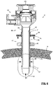
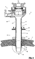
FIG. 1 is a perspective view of a surgical access device illustrating a fixation mechanism in a deployed configuration in accordance with a first aspect of the present disclosure; -
FIG. 2 is an assembly view of the surgical access device ofFIG. 1 ; -
FIG. 3 is a perspective view of the area of detail indicated inFIG. 1 ; -
FIG. 4 is a perspective view of the area of detail indicated inFIG. 2 ; -
FIG. 5 is a perspective view of the surgical access device ofFIG. 1 illustrating a portion of the fixation mechanism within tissue in an undeployed configuration; -
FIG. 6 is a longitudinal cross-sectional view of the surgical access device taken along section line 6-6 inFIG. 5 ; -
FIG. 7 is a longitudinal cross-sectional view of the area of detail indicated inFIG. 6 ; -
FIG. 8 is a longitudinal cross-sectional view of the area of detail indicated inFIG. 9 ; -
FIG. 9 is a longitudinal cross-sectional view of the surgical access device taken along section line 9-9 inFIG. 1 illustrating a portion of the fixation mechanism within tissue in a deployed configuration; -
FIG. 10 is a perspective view of a surgical access device illustrating a fixation mechanism in a deployed configuration in accordance with a second aspect of the present disclosure; -
FIG. 11 is an assembly view of the surgical access device ofFIG. 10 ; -
FIG. 12 is a perspective view of a distal portion of the surgical access device ofFIG. 10 illustrating a portion of the fixation mechanism in a deployed configuration; -
FIG. 13 is a perspective view of a distal portion of the surgical access device ofFIG. 10 illustrating a portion of the fixation mechanism in an undeployed configuration; -
FIG. 14 is an assembly view of a portion of the fixation mechanism of the surgical access device ofFIG. 10 ; -
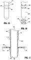
FIG. 15 is a perspective view of a distal portion of an obturator assembly including a portion of the fixation mechanism of the surgical access device ofFIG. 10 ; -
FIG. 16 is an assembly view of the distal portion of an obturator assembly and a portion of the fixation mechanism of the surgical access device ofFIG. 10 ; -
FIG. 17 is a longitudinal cross-sectional view of the surgical access device taken along section line 17-17 inFIG. 12 ; -
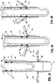
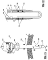
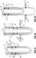
FIGS. 18-20 are longitudinal cross-sectional views of a distal portion of the surgical access device ofFIG. 10 illustrating portions of the fixation mechanism at various stages of retraction; -
FIG. 21 is a perspective view of the surgical access device ofFIG. 10 illustrating a portion of the fixation mechanism within tissue and in an undeployed configuration; -
FIG. 22 is a longitudinal cross-sectional view of the surgical access device taken along section line 22-22 inFIG. 21 ; -
FIGS. 23-25 are longitudinal cross-sectional views of a distal portion of the surgical access device ofFIG. 10 illustrating portions of the fixation mechanism at various stages of deployment; -
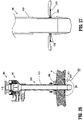
FIG. 26 is a longitudinal cross-sectional view of the surgical access device ofFIG. 10 illustrating a portion of the fixation mechanism within tissue and in a deployed configuration; and -
FIG. 27 is a longitudinal cross-sectional view of the area of detail indicated inFIG. 26 . - Aspects of the presently disclosed surgical access device will now be described in detail with reference to the drawings wherein like numerals designate identical or corresponding elements in each of the several views. As is common in the art, the term "proximal" refers to that part or component closer to the user or operator, i.e. surgeon or physician, while the term "distal" refers to that part or component farther away from the user. As used herein, the terms "parallel" and "perpendicular" are understood to include relative configurations that are substantially parallel and substantially perpendicular up to about + or - 10 degrees from true parallel and true perpendicular, respectively, for example
- Generally, the surgical access device or cannula, often part of a trocar assembly, may be employed during surgery (e.g., laparoscopic surgery) and may, in various aspects, provide for the sealed access of laparoscopic surgical instruments into an insufflated body cavity, such as the abdominal cavity. The cannula is usable with an obturator insertable therethrough. The cannula and obturator are separate components but are capable of being selectively connected together. For example, the obturator may be inserted into and through the cannula until the handle of the obturator engages, e.g., selectively locks into, a proximal housing of the cannula. In this initial configuration, the trocar assembly is employed to tunnel through an anatomical structure, e.g., the abdominal wall, either by making a new passage through the structure or by passing through an existing opening through the structure. Once the trocar assembly has tunneled through the anatomical structure, the obturator is removed, leaving the cannula in place in the structure, e.g., in the incision created by the trocar assembly. The proximal housing of the cannula may include seals or valves that prevent the escape of insufflation gases from the body cavity, while also allowing surgical instruments to be inserted into the body cavity.
-
FIGS. 1-7 illustrate a surgical access device according to a first aspect of the present disclosure. With initial reference toFIGS. 1 and2 , thesurgical access device 10 includes acannula body 100, and afixation mechanism 200. Thecannula body 100 includes aproximal housing 120 at its proximal end and includes anelongated portion 140 extending distally from theproximal housing 120. Theelongated portion 140 defines a channel 150 (FIG. 2 ) extending therethrough, and defines a longitudinal axis "A-A." An obturator (not shown) is insertable through thechannel 150 and is engageable with theproximal housing 120, for instance. - For a detailed description of the structure and function of an exemplary surgical access device including a fixation mechanism having a biasing element, please refer to commonly owned
U.S. Patent Application Serial No. 17/083,916 , the contents of which is incorporated by reference herein in its entirety. - The
fixation mechanism 200 is positionable around theelongated portion 140 of thecannula body 100 such that such that thefixation mechanism 200 radially surrounds a portion of theelongated portion 140. More particularly, portions of thefixation mechanism 200 are longitudinally translatable along theelongated portion 140 between a first position where aproximal part 211 of acollar 210 of thefixation mechanism 200 is farther away from adistal tip 141 of theelongated portion 140 and where amid-portion 222 of anexpandable member 220 of thefixation mechanism 200 is closer to the longitudinal axis "A-A" (FIGS. 5 - 7 ), and a second position, where theproximal part 211 of thecollar 210 is closer to thedistal tip 141 of theelongated portion 140 and where themid-portion 222 of theexpandable member 220 is farther away from the longitudinal axis "A-A" (FIG. 8 and9 ). - Referring to
FIGS. 1 and2 , the engagement between thefixation mechanism 200 and thecannula body 100 is shown. Thefixation mechanism 200 includes thecollar 210, asleeve 215 extending distally from thecollar 210, aproximal ring 216 disposed at a distal end of thesleeve 215, theexpandable member 220, adistal ring 225, and abiasing element 230. Aproximal end 224 of theexpandable member 220 includes a lip that is engaged with (e.g., positioned within a channel of) theproximal ring 216, and adistal end 226 of theexpandable member 220 includes a lip that is engaged with (e.g., positioned within achannel 227 of) the distal ring 225 (seeFIG. 4 ). - The
collar 210, thesleeve 215, and theproximal ring 216 are longitudinally translatable relative to theelongated portion 140 of thecannula body 100. Alip 141a (FIG. 2 ) of thedistal tip 141 of theelongated portion 140 restricts distal movement of thedistal ring 225 relative to theelongated portion 140. Distal movement of theproximal end 224 of theexpandable member 220 relative to theelongated portion 140 causes themid-portion 222 of theexpandable member 220 to move away from the longitudinal axis "A-A." - The biasing element 230 (e.g., a compression spring) radially surrounds the
elongated portion 140 of thecannula body 100, and is positioned between a distal portion of theproximal housing 120 of thecannula body 100 and a proximal portion of thecollar 210 of thefixation mechanism 200. The biasingelement 230 biases thecollar 210 distally relative to theelongated portion 140, in the general direction of arrow "B" inFIG. 1 , such that theexpandable member 220 is biased towards its second position (FIGS. 1 ,3 ,8 , and9 ). To overcome the bias of the biasingelement 230, a user pullsarms 214 of thecollar 210 proximally relative to theelongated portion 140, in the general direction of arrow "C" inFIG. 5 , such that theexpandable member 220 moves towards its first position (FIGS. 5-7 ). - Referring now to
FIGS. 3 and 4 , detailed views of theexpandable member 220 and thedistal ring 225 are shown. In the illustrated aspect, theexpandable member 220 includes foursections proximal end 224, the mid-portion 222, and thedistal end 226. A lip of theproximal end 224 fits at least partially within a channel 217 (FIGS. 7 and 8 ) of theproximal ring 216, and a lip of thedistal end 226 fits at least partially within thechannel 227 of thedistal ring 225. That is, each section 223 of theexpandable member 220 is longitudinally bound between theproximal ring 216 and thedistal ring 225. Additionally, each section 223 of theexpandable member 220 rotatably engages theproximal ring 216 and thedistal ring 225. - With reference to
FIG. 5 , theexpandable member 220 defines a plurality ofdiamondlike openings 221 around its perimeter. Theopenings 221 are configured such thatnarrow portions 221a thereof are located at theproximal end 224 and thedistal end 226 of theexpandable member 220, and awide portion 221b of eachopening 221 is located at or near the mid-portion 222 of theexpandable member 220. This configuration allows or facilitates theexpandable member 220 to effectively bend or fold (and unfold) at or near its mid-portion 222 as thefixation mechanism 200 transitions between its first position and its second position. In aspects, theexpandable member 220 includes a perforation or crease at or near the mid-portion 222 to further facilitate bending and/or folding. - In various aspects, the
expandable member 220 is made of rubber or plastic. Such a rubber or plasticexpandable member 220 is able to retain its shape (in both the first position and the second position) without the need for theexpandable member 220 to be filled with fluid (e.g., liquid or gas), for instance. - Referring now to
FIGS. 1 ,2 ,5 ,6 , and9 , ananchor 400 is shown. Theanchor 400 is positionable around theelongated portion 140 of thecannula body 100 such that theanchor 400 radially surrounds a portion of theelongated portion 140. Theanchor 400 can either have a frictional engagement with theelongated portion 140 such that theanchor 400 can be pushed/pulled to move between longitudinal positions, or theanchor 400 can be rotationally engaged with the elongated portion 140 (e.g., a threaded connection) such that theanchor 400 can be rotated about the longitudinal axis "A-A" relative to theelongated portion 140 to move between longitudinal positions. Theanchor 400 may also be fixed from longitudinal and/or rotational movement relative to theelongated portion 140. - In use, when the
fixation mechanism 200 is in its first position (FIGS. 5-7 ) corresponding to theexpandable member 220 being in its first position, and the biasingelement 230 being in the compressed orientation (e.g., a user is pulling thearms 214 of thecollar 210 proximally), thedistal tip 141 of theelongated portion 140 of thecannula body 100 is inserted through an incision in tissue. Engagement between theanchor 400 and a proximal wall of the tissue prevents additional insertion of thecannula body 100. - To transition the
fixation mechanism 200 to its second position (FIGS. 1 ,3 ,8 , and9 ), the user releases the proximal force exerted on thearms 214 thereby allowing the biasingelement 230 to expand distally into its second orientation, which moves thecollar 210 distally. This distal movement of thecollar 210 relative to theelongated portion 140 causes thesleeve 215 andproximal ring 216 to move distally relative to theelongated portion 140 and relative to thedistal ring 225. Further, as discussed above, this distal movement causes themid-portion 222 of theexpandable member 220 to move away from theelongated portion 140. In this position, thesurgical access device 10 can be moved proximally relatively to the tissue "T" such that theexpandable member 220 engages a distal portion of the tissue wall "T" (FIG. 9 ). - Next, in aspects where the
anchor 400 is longitudinally movable relative theelongated portion 140 of thecannula body 100, theanchor 400 is moved distally such that theanchor 400 contacts a proximal portion of the tissue wall "T," thereby sandwiching the tissue wall "T" between theanchor 400 and theexpandable member 220, and fixing the longitudinal position of thecannula body 100 relative to the tissue wall "T." - Referring now to
FIGS. 10-27 , a surgical access device according to a second aspect of the present disclosure is shown. With initial reference toFIGS. 10 and11 , thesurgical access device 500 includes acannula body 1000, anobturator assembly 2000, and afixation mechanism 3000. - The
cannula body 1000 includes ahousing 1200 at its proximal end and includes anelongated portion 1400 extending distally from thehousing 1200. Theelongated portion 1400 defines a channel 1500 (FIG. 11 ) extending therethrough, and defines a longitudinal axis "B-B." - The
obturator assembly 2000 includes aproximal end 2200 and anelongated portion 2400 extending distally from theproximal end 2200. Theelongated portion 2400 defines a channel 2500 (FIG. 11 ) extending therein, which is configured to allow a portion of a surgical instrument to be inserted therein. At least part of theelongated portion 2400 of theobturator assembly 2000 is insertable through thechannel 1500 defined by theelongated portion 1400 of thecannula body 1000, and theproximal end 2200 of theobturator assembly 2000 is engageable with thehousing 1200 of the cannula body. - The
fixation mechanism 3000 includes at least onewing 3100 coupled to theelongated portion 1400 of thecannula body 1000, a first plurality ofmagnets 3200 disposed in mechanical cooperation with theelongated portion 2400 of theobturator assembly 2000, and a second plurality of magnets 3300 (FIGS. 19, 20 ,22 ,24, 25 , and27 ) disposed in mechanical cooperation with the at least onewing 3100 of the fixation mechanism. - As will be described in further detail below, insertion of the
elongated portion 2400 of theobturator assembly 2000 through thechannel 1500 of thecannula body 1000 causes the first plurality ofmagnets 3200 to magnetically engage the second plurality ofmagnets 3300, which causes the at least onewing 3100 of thefixation mechanism 3000 to move between a first position (FIGS. 11 ,13 , and21-23 ), where the at least onewing 3100 is disposed generally parallel to the longitudinal axis "B-B", and a second position (FIGS. 10 ,12 ,17 ,18 , and24-27 ), where the at least onewing 3100 is disposed generally perpendicular to the longitudinal axis "B-B." - Referring to
FIGS. 12, 14 ,17 , and23 , thefixation mechanism 3000 includes afirst wing 3100a and asecond wing 3100b. Eachwing elongated portion 1400 of thecannula body 1000, and is pivotable between a first position (FIGS. 12 and17 ) where thewings FIGS. 13, 14 , and21-23 ) thewings respective recesses elongated portion 1400 and generally parallel to the longitudinal axis "B-B." Gravity biases thewings wings wings - More particularly, with reference to
FIGS. 12-14 , eachwing respective pin pin slot 1412 ofrespective recesses wing 3100 and theelongated portion 1400. - Additionally, while two
wings fixation mechanism 3000 may include more or fewer wings without departing from the scope of the present disclosure. - With particular reference to
FIGS. 15 and 16 , the first plurality ofmagnets 3200 includes afirst magnet 3220 disposed at least partially within a first annular groove orchannel 2420 within an outer wall of theelongated portion 2400 of theobturator assembly 2000, and asecond magnet 3230 disposed at least partially within a second annular groove orchannel 2430 with the outer wall of theelongated portion 2400 of theobturator assembly 2000. Thefirst magnet 3220 is disposed proximally of thesecond magnet 3230 and has a first polarity (e.g., positive), and thesecond magnet 3230 has a second, opposite polarity (e.g., negative). - With reference to
FIG. 17 , the second plurality ofmagnets 3300 includes afirst magnet 3320 disposed at least partially within an inner wall of the at least onewing 3100, and asecond magnet 3330 disposed at least partially within an outer all of the at least onewing 3100. Thefirst magnet 3320 is disposed proximally of the second magnet 3330 (when the at least onewing 3100 is generally parallel to the longitudinal axis "B-B") and has the same polarity (negative) as thesecond magnet 3230 of the first plurality ofmagnets 3200. Thesecond magnet 3330 has the same polarity (negative) as thefirst magnet 3320 of the second plurality ofmagnets 3300 and the same polarity as thesecond magnet 3230 of the first plurality ofmagnets 3200. - In the illustrated aspect, the
first magnet 3220 and thesecond magnet 3230 of the first plurality ofmagnets 3200 are annular rings, such that regardless of the rotational position of theobturator assembly 2000 relative to thecannula body 1000, the first plurality ofmagnets 3200 will be able to magnetically engage (i.e., attract and/or repel) the second plurality ofmagnets 3300. - Referring now to
FIGS. 17-27 , various steps illustrating the use of thesurgical access device 500 and thefixation mechanism 3000 are shown.FIG. 17 shows thewings fixation mechanism 3000 in the first position, and prior to theelongated portion 2400 of theobturator assembly 2000 being inserted through thechannel 1500 of thecannula body 1000. InFIG. 18 , part of theelongated portion 2400 of theobturator assembly 2000 is within thechannel 1500 of thecannula body 1000. The first plurality ofmagnets 3200 of theelongated portion 2400 of theobturator assembly 2000 are too far from the second plurality ofmagnets 3300 of the at least onewing 3100 to result in any perceptible magnetic forces therebetween. - Referring to
FIGS. 19 and 20 , the pivoting of thewings magnets 3200 of theelongated portion 2400 magnetically engages the second plurality ofmagnets 3300 of thewings second magnet 3230 of the first plurality ofmagnets 3200 is advanced longitudinally such that thesecond magnet 3230 is approximately aligned with the distal orsecond magnet 3330 of the second plurality ofmagnets 3300, thesecond magnet 3230 of the first plurality ofmagnets 3200 repels thesecond magnet 3330 of the second plurality ofmagnets 3300, resulting in thewings cannula body 1000 into tissue is facilitated. -
FIGS. 21 and 22 show theelongated portion 2400 of theobturator assembly 2000 fully advanced within thechannel 1500 of thecannula body 1000, and thewings second magnet 3230 of the first plurality ofmagnets 3200 repelling thesecond magnet 3330 of the second plurality ofmagnets 3300, thefirst magnet 3220 of the first plurality ofmagnets 3200 attracts the oppositely-polarizedfirst magnet 3320 of the second plurality ofmagnets 3300. In this position, the distal portion of thesurgical access device 500 can be inserted into tissue "T" (FIG. 21 ). - Referring now to
FIGS. 23-25 , to return thewings wings obturator assembly 2000 is moved proximally relative to thecannula body 1000. During proximal movement of theobturator assembly 2000, the first plurality ofmagnets 3200 on theelongated portion 2400 on theobturator assembly 2000 moves proximally relative to the second plurality ofmagnets 3300 on thewings FIGS. 23 and 24 , thesecond magnet 3230 of the first plurality ofmagnets 3200 is in longitudinal alignment with thefirst magnet 3320 of the second plurality ofmagnets 3300. Since these magnets have opposite polarities, thewings first magnet 3320 of the second plurality ofmagnets 3300, are repelled (and acted on by gravity) such that thewings FIG. 25 shows theelongated portion 2400 of theobturator assembly 2000 move farther proximally, while thewings - With reference to
FIGS. 26 and 27 , thewings obturator assembly 2000 has been removed from thecannula body 1000. Here, thecannula body 1000 can be moved proximally relative to the tissue "T" such thatwings cannula body 1000 relative to the tissue "T." Next, in aspects where ananchor 4000 is used, theanchor 4000 is moved distally such that theanchor 4000 contacts a proximal portion of the tissue "T," thereby sandwiching the tissue "T" between theanchor 4000 and thewings 3 100a, 3 100b, and fixing the longitudinal position of thecannula body 1000 relative to the tissue "T." - While the above description contains many specifics, these specifics should not be construed as limitations on the scope of the present disclosure, but merely as illustrations of various aspects thereof. Therefore, the above description should not be construed as limiting, but merely as exemplifications of various aspects. Those skilled in the art will envision other modifications within the scope and spirit of the claims appended hereto.
- The invention may be described by reference to the following numbered paragraphs:-
- 1. A surgical access device, comprising:
- a cannula body including a housing and an elongated portion extending distally from the housing, the elongated portion defining a longitudinal axis, and defining a channel extending therethrough;
- an obturator assembly including a housing and an elongated portion extending distally from the housing, at least part of the elongated portion configured to be inserted through the channel of the elongated portion of the cannula body; and
- a fixation mechanism including:
- at least one wing coupled to the elongated portion of the cannula body, the at least one wing movable relative to the elongated portion of the cannula between a first position where the at least one wing is parallel to the longitudinal axis, and a second position where the at least one wing is disposed at an angle to the longitudinal axis;
- a first plurality of magnets disposed on the elongated portion of the obturator assembly; and
- a second plurality of magnets disposed on the at least one wing;
- wherein a predetermined amount of translation of the elongated portion of the obturator assembly within the channel of the elongated portion of the cannula body causes the at least one wing to move from the first position to the second position.
- 2. The surgical access device according to paragraph 1, wherein a predetermined amount of proximal translation of the obturator assembly relative to the cannula body causes the at least one wing to move from the first position to the second position.
- 3. The surgical access device according to paragraph 2, wherein a predetermined amount of distal translation of the obturator assembly relative to the cannula body causes the at least one wing to move from the second position to the first position.
- 4. The surgical access device according to paragraph 1, wherein the at least one wing includes a first wing and a second wing.
- 5. The surgical access device according to
paragraph 4, wherein a first magnet of the first plurality of magnets has a first polarity and a second magnet of the first plurality of magnets has a second polarity, the first polarity being opposite from the second polarity. - 6. The surgical access device according to paragraph 1, wherein the first plurality of magnets includes a first magnet defining an annular ring.
- 7. The surgical access device according to
paragraph 6, wherein the first plurality of magnets includes a second magnet defining an annular ring. - 8. The surgical access device according to paragraph 1, wherein the at least one wing is biased towards the second position.
- 9. The surgical access device according to paragraph 1, wherein a first magnet and a second magnet of the second plurality of magnets have the same polarity as each other.
- 10. The surgical access device according to
paragraph 9, wherein the first magnet of the second plurality of magnets is on an inner surface of the at least one wing and the second magnet of the second plurality of magnets is on an outer surface of the at least one wing. - 11. The surgical access device according to paragraph 5, wherein the second plurality of magnets includes a first magnet and a second magnet, the first magnet and the second magnet of the second plurality of magnets have the same polarity as each other and as the second magnet of the first plurality of magnets, and the second magnet of the first plurality of magnets is disposed distally of the second magnet of the first plurality of magnets.
- 12. A surgical access device, comprising:
- a cannula body including a housing and an elongated portion extending distally from the housing, the elongated portion defining a longitudinal axis, and defining a channel extending therethrough; and
- a fixation mechanism including:
- a wing pivotably engaged with the elongated portion of the cannula body and movable between a first position where the wing is parallel to the longitudinal axis, and a second position where the wing is disposed at an angle to the longitudinal axis; and
- a first magnet disposed on the wing;
- wherein a predetermined amount of translation of an obturator assembly within the channel of the elongated portion of the cannula body causes the wing to move from the first position to the second position.
- 13. The surgical access device according to paragraph 12, further including a second magnet disposed on the wing.
- 14. The surgical access device according to paragraph 13, wherein the first magnet is disposed proximally of the second magnet when the wing is in the first position.
- 15. The surgical access device according to paragraph 12, wherein when the wing is in the second position, the wing is perpendicular to the longitudinal axis.
- 16. The surgical access device according to paragraph 15, wherein the wing is biased towards the second position.
- 17. A method of deploying a fixation mechanism of a surgical access device, including:
- inserting an elongated portion of an obturator assembly at least partially through a channel of a cannula body; and
- advancing the obturator assembly distally relative to the cannula body such that a first magnet on the elongated portion of the obturator assembly attracts a first magnet of a wing of the cannula body, thereby causing the wing to pivot relative to the cannula body such that the wing is parallel to a longitudinal axis defined by the channel.
- 18. The method according to
paragraph 17, further including retracting the obturator assembly proximally relative to the cannula body such that a second magnet on the elongated portion of the obturator assembly repels the first magnet of the wing of the cannula body, thereby causing the wing to pivot relative to the cannula body such that the wing is disposed at an angle to a longitudinal axis. - 19. The method according to paragraph 18, wherein advancing the obturator assembly distally relative to the cannula body causes the second magnet on the elongated portion of the obturator assembly to repel a second magnet of the wing of the cannula body.
- 20. The method according to
paragraph 17, wherein advancing the obturator assembly distally relative to the cannula body causes a second magnet on the elongated portion of the obturator assembly to repel a second magnet of the wing of the cannula body.
Claims (15)
- A surgical access device, comprising:a cannula body including a housing and an elongated portion extending distally from the housing, the elongated portion defining a longitudinal axis, and defining a channel extending therethrough;an obturator assembly including a housing and an elongated portion extending distally from the housing, at least part of the elongated portion configured to be inserted through the channel of the elongated portion of the cannula body; anda fixation mechanism including:at least one wing coupled to the elongated portion of the cannula body, the at least one wing movable relative to the elongated portion of the cannula between a first position where the at least one wing is parallel to the longitudinal axis, and a second position where the at least one wing is disposed at an angle to the longitudinal axis;a first plurality of magnets disposed on the elongated portion of the obturator assembly; anda second plurality of magnets disposed on the at least one wing;wherein a predetermined amount of translation of the elongated portion of the obturator assembly within the channel of the elongated portion of the cannula body causes the at least one wing to move from the first position to the second position.
- The surgical access device according to claim 1, wherein a predetermined amount of proximal translation of the obturator assembly relative to the cannula body causes the at least one wing to move from the first position to the second position.
- The surgical access device according to claim 2, wherein a predetermined amount of distal translation of the obturator assembly relative to the cannula body causes the at least one wing to move from the second position to the first position.
- The surgical access device according to any preceding claim, wherein the at least one wing includes a first wing and a second wing.
- The surgical access device according to claim 4, wherein a first magnet of the first plurality of magnets has a first polarity and a second magnet of the first plurality of magnets has a second polarity, the first polarity being opposite from the second polarity.
- The surgical access device according to any preceding claim, wherein the first plurality of magnets includes a first magnet defining an annular ring; preferably wherein the first plurality of magnets includes a second magnet defining an annular ring.
- The surgical access device according to any preceding claim, wherein the at least one wing is biased towards the second position.
- The surgical access device according to any preceding claim, wherein a first magnet and a second magnet of the second plurality of magnets have the same polarity as each other; preferably wherein the first magnet of the second plurality of magnets is on an inner surface of the at least one wing and the second magnet of the second plurality of magnets is on an outer surface of the at least one wing.
- The surgical access device according to claim 5, wherein the second plurality of magnets includes a first magnet and a second magnet, the first magnet and the second magnet of the second plurality of magnets have the same polarity as each other and as the second magnet of the first plurality of magnets, and the second magnet of the first plurality of magnets is disposed distally of the second magnet of the first plurality of magnets.
- A surgical access device, comprising:a cannula body including a housing and an elongated portion extending distally from the housing, the elongated portion defining a longitudinal axis, and defining a channel extending therethrough; anda fixation mechanism including:a wing pivotably engaged with the elongated portion of the cannula body and movable between a first position where the wing is parallel to the longitudinal axis, and a second position where the wing is disposed at an angle to the longitudinal axis; anda first magnet disposed on the wing;wherein a predetermined amount of translation of an obturator assembly within the channel of the elongated portion of the cannula body causes the wing to move from the first position to the second position.
- The surgical access device according to claim 10, further including a second magnet disposed on the wing; preferably wherein the first magnet is disposed proximally of the second magnet when the wing is in the first position.
- The surgical access device according to claim 10 or claim 11, wherein when the wing is in the second position, the wing is perpendicular to the longitudinal axis; preferably wherein the wing is biased towards the second position.
- A method of deploying a fixation mechanism of a surgical access device, including:inserting an elongated portion of an obturator assembly at least partially through a channel of a cannula body; andadvancing the obturator assembly distally relative to the cannula body such that a first magnet on the elongated portion of the obturator assembly attracts a first magnet of a wing of the cannula body, thereby causing the wing to pivot relative to the cannula body such that the wing is parallel to a longitudinal axis defined by the channel.
- The method according to claim 13, further including retracting the obturator assembly proximally relative to the cannula body such that a second magnet on the elongated portion of the obturator assembly repels the first magnet of the wing of the cannula body, thereby causing the wing to pivot relative to the cannula body such that the wing is disposed at an angle to a longitudinal axis; preferably wherein advancing the obturator assembly distally relative to the cannula body causes the second magnet on the elongated portion of the obturator assembly to repel a second magnet of the wing of the cannula body.
- The method according to claim 14, wherein advancing the obturator assembly distally relative to the cannula body causes a second magnet on the elongated portion of the obturator assembly to repel a second magnet of the wing of the cannula body.
Applications Claiming Priority (1)
| Application Number | Priority Date | Filing Date | Title |
|---|---|---|---|
| US17/101,135 US12137934B2 (en) | 2020-11-23 | 2020-11-23 | Surgical access device with fixation mechanism |
Publications (1)
| Publication Number | Publication Date |
|---|---|
| EP4000544A1 true EP4000544A1 (en) | 2022-05-25 |
Family
ID=78709269
Family Applications (1)
| Application Number | Title | Priority Date | Filing Date |
|---|---|---|---|
| EP21209207.6A Withdrawn EP4000544A1 (en) | 2020-11-23 | 2021-11-19 | Surgical access device with fixation mechanism |
Country Status (2)
| Country | Link |
|---|---|
| US (2) | US12137934B2 (en) |
| EP (1) | EP4000544A1 (en) |
Citations (6)
| Publication number | Priority date | Publication date | Assignee | Title |
|---|---|---|---|---|
| US20060079925A1 (en) * | 2002-10-23 | 2006-04-13 | Stephen Kerr | Direct vision port site dissector |
| US20080287740A1 (en) * | 2007-05-18 | 2008-11-20 | Barry Weitzner | Methods and devices for traversing an anatomic wall |
| US20110144447A1 (en) * | 2009-12-11 | 2011-06-16 | Ethicon Endo-Surgery, Inc. | Methods and devices for providing access through tissue to a surgical site |
| US20130053782A1 (en) * | 2011-08-25 | 2013-02-28 | Frederick E. Shelton, IV | Surgical Access Device with Adjustable Cannula |
| US20150297260A1 (en) * | 2012-11-20 | 2015-10-22 | Trokasure Gbr | Trocar device and use thereof |
| US20160038018A1 (en) * | 2013-03-13 | 2016-02-11 | Vantage Surgical Systems, Inc. | Merged trocar-obturator device for optical-entry in minimally invasive surgery |
Family Cites Families (163)
| Publication number | Priority date | Publication date | Assignee | Title |
|---|---|---|---|---|
| US512456A (en) | 1894-01-09 | Garland b | ||
| US397060A (en) | 1889-01-29 | Island | ||
| US1213005A (en) | 1914-12-22 | 1917-01-16 | Victor Czeskleba | Obstetrical instrument. |
| US2936760A (en) | 1956-09-10 | 1960-05-17 | Davol Rubber Co | Positive pressure catheter |
| US2912981A (en) | 1958-04-10 | 1959-11-17 | Frank J Keough | Inflatable retention catheter |
| US3050066A (en) | 1958-12-31 | 1962-08-21 | Wilbur R Koehn | Retention catheters |
| US3039468A (en) | 1959-01-07 | 1962-06-19 | Joseph L Price | Trocar and method of treating bloat |
| US3253594A (en) | 1963-07-30 | 1966-05-31 | Frank E Matthews | Peritoneal cannula |
| US3397699A (en) | 1966-05-05 | 1968-08-20 | Gerald C. Kohl | Retaining catheter having resiliently biased wing flanges |
| US3545443A (en) | 1968-09-26 | 1970-12-08 | Amir H Ansari | Suprapubic cystostomy needle |
| US3896816A (en) | 1971-05-03 | 1975-07-29 | Martin Mattler | Disposable catheter |
| US3774596A (en) | 1971-06-29 | 1973-11-27 | G Cook | Compliable cavity speculum |
| US3713447A (en) | 1971-08-16 | 1973-01-30 | E Adair | Suprapubic shunt |
| US3800788A (en) | 1972-07-12 | 1974-04-02 | N White | Antral catheter for reduction of fractures |
| USRE29207E (en) | 1973-06-25 | 1977-05-10 | Population Research Incorporated | Dispensing method and apparatus |
| US3882852A (en) | 1974-01-11 | 1975-05-13 | Manfred Sinnreich | Surgical dilators having insufflating means |
| US3961632A (en) | 1974-12-13 | 1976-06-08 | Moossun Mohamed H | Stomach intubation and catheter placement system |
| US4083369A (en) | 1976-07-02 | 1978-04-11 | Manfred Sinnreich | Surgical instruments |
| US4217889A (en) | 1976-09-15 | 1980-08-19 | Heyer-Schulte Corporation | Flap development device and method of progressively increasing skin area |
| US4345606A (en) | 1977-12-13 | 1982-08-24 | Littleford Philip O | Split sleeve introducers for pacemaker electrodes and the like |
| US4243050A (en) | 1977-12-13 | 1981-01-06 | Littleford Philip O | Method for inserting pacemaker electrodes and the like |
| US4327709A (en) | 1978-03-06 | 1982-05-04 | Datascope Corp. | Apparatus and method for the percutaneous introduction of intra-aortic balloons into the human body |
| US4276874A (en) | 1978-11-15 | 1981-07-07 | Datascope Corp. | Elongatable balloon catheter |
| US4312353A (en) | 1980-05-09 | 1982-01-26 | Mayfield Education And Research Fund | Method of creating and enlarging an opening in the brain |
| US4411654A (en) | 1981-04-30 | 1983-10-25 | Baxter Travenol Laboratories, Inc. | Peelable catheter with securing ring and suture sleeve |
| US4899747A (en) | 1981-12-10 | 1990-02-13 | Garren Lloyd R | Method and appartus for treating obesity |
| US4416267A (en) | 1981-12-10 | 1983-11-22 | Garren Lloyd R | Method and apparatus for treating obesity |
| US4496345A (en) | 1982-08-30 | 1985-01-29 | Hasson Harrith M | Ballooned cannula |
| US4490137A (en) | 1982-09-30 | 1984-12-25 | Moukheibir Nabil W | Surgically implantable peritoneal dialysis apparatus |
| US4644936A (en) | 1982-11-19 | 1987-02-24 | Iabp | Percutaneous intra-aortic balloon and method for using same |
| US4581025A (en) | 1983-11-14 | 1986-04-08 | Cook Incorporated | Sheath |
| US4574806A (en) | 1984-10-01 | 1986-03-11 | Cordis Corporation | Tunnelling device for peripheral vascular reconstruction |
| US4596559A (en) | 1984-11-02 | 1986-06-24 | Fleischhacker John J | Break-away handle for a catheter introducer set |
| US4701163A (en) | 1984-11-05 | 1987-10-20 | Medical Innovations Corporation | Gastrostomy feeding device |
| US4685447A (en) | 1985-03-25 | 1987-08-11 | Pmt Corporation | Tissue expander system |
| US4608965A (en) | 1985-03-27 | 1986-09-02 | Anspach Jr William E | Endoscope retainer and tissue retracting device |
| US4596554A (en) | 1985-04-19 | 1986-06-24 | Dastgeer Ghulam M | Colo-rectal evacuator |
| US4917088A (en) | 1985-05-02 | 1990-04-17 | C. R. Bard, Inc. | Balloon dilation probe |
| US4738666A (en) | 1985-06-11 | 1988-04-19 | Genus Catheter Technologies, Inc. | Variable diameter catheter |
| US4654030A (en) | 1986-02-24 | 1987-03-31 | Endotherapeutics | Trocar |
| US4769038A (en) | 1986-03-18 | 1988-09-06 | C. R. Bard, Inc. | Prostheses and techniques and repair of inguinal and femoral hernias |
| US4798205A (en) | 1986-05-08 | 1989-01-17 | Cox-Uphoff International | Method of using a subperiosteal tissue expander |
| IL78756A0 (en) | 1986-05-12 | 1986-08-31 | Biodan Medical Systems Ltd | Catheter and probe |
| US4854316A (en) | 1986-10-03 | 1989-08-08 | Davis Emsley A | Apparatus and method for repairing and preventing para-stomal hernias |
| US5030206A (en) | 1986-10-17 | 1991-07-09 | United States Surgical Corporation | Trocar |
| US4802479A (en) | 1986-10-31 | 1989-02-07 | C. R. Bard, Inc. | Hand-held instrument for implanting, dispensing, and inflating an inflatable membrane |
| US4793348A (en) | 1986-11-15 | 1988-12-27 | Palmaz Julio C | Balloon expandable vena cava filter to prevent migration of lower extremity venous clots into the pulmonary circulation |
| US5030227A (en) | 1988-06-02 | 1991-07-09 | Advanced Surgical Intervention, Inc. | Balloon dilation catheter |
| JPS63158064A (en) | 1986-12-23 | 1988-07-01 | テルモ株式会社 | Blood vessel dilating catheter |
| US4784133A (en) | 1987-01-28 | 1988-11-15 | Mackin Robert A | Working well balloon angioscope and method |
| US4779611A (en) | 1987-02-24 | 1988-10-25 | Grooters Ronald K | Disposable surgical scope guide |
| US4772266A (en) | 1987-05-04 | 1988-09-20 | Catheter Technology Corp. | Catheter dilator/sheath assembly and method |
| GB2205751A (en) | 1987-06-04 | 1988-12-21 | Femcare Ltd | Insertion of catheters |
| JPS642662A (en) | 1987-06-25 | 1989-01-06 | Nippon Sherwood Kk | Easy split plastic cannula excellent in stability |
| US4800901A (en) | 1987-09-09 | 1989-01-31 | Lior Rosenberg | Balloon-type Tissue expansion device |
| US4931042A (en) | 1987-10-26 | 1990-06-05 | Endotherapeutics | Trocar assembly with improved latch |
| DE3809127C1 (en) | 1988-03-18 | 1989-04-13 | B. Braun Melsungen Ag, 3508 Melsungen, De | |
| US4869717A (en) | 1988-04-25 | 1989-09-26 | Adair Edwin Lloyd | Gas insufflation needle with instrument port |
| US4840613A (en) | 1988-04-27 | 1989-06-20 | Menlo Care, Inc. | Protective sheath for catheter assembly |
| US4861334A (en) | 1988-06-24 | 1989-08-29 | Nawaz Arain | Self-retaining gastrostomy tube |
| US5215526A (en) | 1988-07-06 | 1993-06-01 | Ethicon, Inc. | Safety trocar |
| US6120437A (en) | 1988-07-22 | 2000-09-19 | Inbae Yoon | Methods for creating spaces at obstructed sites endoscopically and methods therefor |
| US5514091A (en) | 1988-07-22 | 1996-05-07 | Yoon; Inbae | Expandable multifunctional manipulating instruments for various medical procedures |
| US5159925A (en) | 1988-09-09 | 1992-11-03 | Gynelab, Inc. | Cauterizing apparatus and method for laparoscopic cholecystostomy, gallbladder ablation and treatment of benign prostate hypertrophy |
| US5183463A (en) | 1989-02-03 | 1993-02-02 | Elie Debbas | Apparatus for locating a breast mass |
| US5137512A (en) | 1989-03-17 | 1992-08-11 | Scimed Life Systems, Inc. | Multisegment balloon protector for dilatation catheter |
| US5176697A (en) | 1989-04-06 | 1993-01-05 | Hasson Harrith M | Laparoscopic cannula |
| US5002557A (en) | 1989-04-06 | 1991-03-26 | Hasson Harrith M | Laparoscopic cannula |
| US5147302A (en) | 1989-04-21 | 1992-09-15 | Scimed Life Systems, Inc. | Method of shaping a balloon of a balloon catheter |
| US5116318A (en) | 1989-06-06 | 1992-05-26 | Cordis Corporation | Dilatation balloon within an elastic sleeve |
| US5009643A (en) | 1989-08-09 | 1991-04-23 | Richard Wolf Medical Instruments Corp. | Self-retaining electrically insulative trocar sleeve and trocar |
| US5104383A (en) | 1989-10-17 | 1992-04-14 | United States Surgical Corporation | Trocar adapter seal and method of use |
| US5122122A (en) | 1989-11-22 | 1992-06-16 | Dexide, Incorporated | Locking trocar sleeve |
| US5330497A (en) | 1989-11-22 | 1994-07-19 | Dexide, Inc. | Locking trocar sleeve |
| US5232451A (en) | 1989-11-22 | 1993-08-03 | Dexide, Inc. | Locking trocar sleeve |
| US5074871A (en) | 1989-12-07 | 1991-12-24 | Evi Corporation | Catheter atherotome |
| US5141494A (en) | 1990-02-15 | 1992-08-25 | Danforth Biomedical, Inc. | Variable wire diameter angioplasty dilatation balloon catheter |
| US5163949A (en) | 1990-03-02 | 1992-11-17 | Bonutti Peter M | Fluid operated retractors |
| US5514153A (en) | 1990-03-02 | 1996-05-07 | General Surgical Innovations, Inc. | Method of dissecting tissue layers |
| US5345927A (en) | 1990-03-02 | 1994-09-13 | Bonutti Peter M | Arthroscopic retractors |
| CA2044867C (en) | 1990-06-25 | 1999-10-12 | James J. Rudnick | Direct vision prostate balloon catheter |
| US5250025A (en) | 1990-08-15 | 1993-10-05 | Intramed Laboratories | Percutaneous access catheter and method of use |
| US5188596A (en) | 1990-09-27 | 1993-02-23 | Mentor Corporation | Transparent prostate dilation balloon and scope |
| CA2052310A1 (en) | 1990-10-09 | 1992-04-10 | Thomas L. Foster | Surgical access sheath |
| WO1992006638A1 (en) | 1990-10-10 | 1992-04-30 | W.L. Gore & Associates, Inc. | A laparoscopy surgical instrument |
| US5141515A (en) | 1990-10-11 | 1992-08-25 | Eberbach Mark A | Apparatus and methods for repairing hernias |
| US5116357A (en) | 1990-10-11 | 1992-05-26 | Eberbach Mark A | Hernia plug and introducer apparatus |
| US5122155A (en) | 1990-10-11 | 1992-06-16 | Eberbach Mark A | Hernia repair apparatus and method of use |
| FR2668695B1 (en) | 1990-11-06 | 1995-09-29 | Ethnor | ENDOSCOPIC SURGICAL INSTRUMENT FOR MOVING TISSUES OR ORGANS. |
| US5147316A (en) | 1990-11-19 | 1992-09-15 | Castillenti Thomas A | Laparoscopic trocar with self-locking port sleeve |
| US5359995A (en) | 1991-02-04 | 1994-11-01 | Sewell Jr Frank | Method of using an inflatable laparoscopic retractor |
| US5188630A (en) | 1991-03-25 | 1993-02-23 | Christoudias George C | Christoudias endospongestick probe |
| DE9106553U1 (en) | 1991-04-10 | 1991-08-08 | Wisap Gesellschaft für wissenschaftlichen Apparatebau mbH, 8029 Sauerlach | Abdominal cavity expander |
| US5209725A (en) | 1991-04-11 | 1993-05-11 | Roth Robert A | Prostatic urethra dilatation catheter system and method |
| US5201742A (en) | 1991-04-16 | 1993-04-13 | Hasson Harrith M | Support jig for a surgical instrument |
| US5158545A (en) | 1991-05-02 | 1992-10-27 | Brigham And Women's Hospital | Diameter expansion cannula |
| US5803901A (en) | 1991-05-29 | 1998-09-08 | Origin Medsystems, Inc. | Inflatable devices for separating layers of tissue and methods of using |
| US5431173A (en) | 1991-05-29 | 1995-07-11 | Origin Medsystems, Inc. | Method and apparatus for body structure manipulation and dissection |
| US6361543B1 (en) | 1991-05-29 | 2002-03-26 | Sherwood Services Ag | Inflatable devices for separating layers of tissue, and methods of using |
| US5468248A (en) | 1991-05-29 | 1995-11-21 | Origin Medsystems, Inc. | Endoscopic inflatable retraction devices for separating layers of tissue |
| US5632761A (en) | 1991-05-29 | 1997-05-27 | Origin Medsystems, Inc. | Inflatable devices for separating layers of tissue, and methods of using |
| US5779728A (en) | 1991-05-29 | 1998-07-14 | Origin Medsystems, Inc. | Method and inflatable chamber apparatus for separating layers of tissue |
| US5383889A (en) | 1991-05-29 | 1995-01-24 | Origin Medsystems, Inc. | Tethered everting balloon retractor for hollow bodies and method of using |
| US5728119A (en) | 1991-05-29 | 1998-03-17 | Origin Medsystems, Inc. | Method and inflatable chamber apparatus for separating layers of tissue |
| US5704372A (en) | 1991-05-29 | 1998-01-06 | Origin Medsystems, Inc. | Endoscopic inflatable retraction devices for separating layers of tissue, and methods of using |
| US5370134A (en) | 1991-05-29 | 1994-12-06 | Orgin Medsystems, Inc. | Method and apparatus for body structure manipulation and dissection |
| US5361752A (en) | 1991-05-29 | 1994-11-08 | Origin Medsystems, Inc. | Retraction apparatus and methods for endoscopic surgery |
| US5098392A (en) | 1991-06-28 | 1992-03-24 | Fleischhacker John J | Locking dilator for peel away introducer sheath |
| US5183033A (en) | 1991-07-15 | 1993-02-02 | Wilk Peter J | Surgical instrument assembly and apparatus and surgical method |
| US5234454A (en) | 1991-08-05 | 1993-08-10 | Akron City Hospital | Percutaneous intragastric balloon catheter and method for controlling body weight therewith |
| US5222970A (en) | 1991-09-06 | 1993-06-29 | William A. Cook Australia Pty. Ltd. | Method of and system for mounting a vascular occlusion balloon on a delivery catheter |
| US5232446A (en) | 1991-10-30 | 1993-08-03 | Scimed Life Systems, Inc. | Multi-sinus perfusion balloon dilatation catheter |
| JPH07500758A (en) | 1991-11-06 | 1995-01-26 | ユーン、インバエ | surgical instrument stabilizer |
| US5226890A (en) | 1991-11-13 | 1993-07-13 | United States Surgical Corporation | Tissue gripping device |
| EP0613351B1 (en) | 1991-11-19 | 1997-03-05 | Origin Medsystems, Inc. | Endoscopic inflatable retraction devices for separating layers of tissue |
| US5308327A (en) | 1991-11-25 | 1994-05-03 | Advanced Surgical Inc. | Self-deployed inflatable retractor |
| US5147374A (en) | 1991-12-05 | 1992-09-15 | Alfredo Fernandez | Prosthetic mesh patch for hernia repair |
| US5176692A (en) | 1991-12-09 | 1993-01-05 | Wilk Peter J | Method and surgical instrument for repairing hernia |
| US5258026A (en) | 1992-02-06 | 1993-11-02 | Johnson Gerald W | Endoscopic augmentation mammoplasty and instruments therefor |
| US5607443A (en) | 1992-06-02 | 1997-03-04 | General Surgical Innovations, Inc. | Expansible tunneling apparatus for creating an anatomic working space with laparoscopic observation |
| US6540764B1 (en) | 1992-06-02 | 2003-04-01 | General Surgical Innovations, Inc. | Apparatus and method for dissecting tissue layers |
| US6432121B1 (en) | 1992-06-02 | 2002-08-13 | General Surgical Innovations, Inc. | Apparatus and method for guiding placement of a minimally invasive surgical instrument |
| US5540711A (en) | 1992-06-02 | 1996-07-30 | General Surgical Innovations, Inc. | Apparatus and method for developing an anatomic space for laparoscopic procedures with laparoscopic visualization |
| US5730756A (en) | 1992-06-02 | 1998-03-24 | General Surgical Innovations, Inc. | Method for developing an anatomic space for laparoscopic procedures with laparoscopic visualization |
| US6312442B1 (en) | 1992-06-02 | 2001-11-06 | General Surgical Innovations, Inc. | Method for developing an anatomic space for laparoscopic hernia repair |
| US5772680A (en) | 1992-06-02 | 1998-06-30 | General Surgical Innovations, Inc. | Apparatus and method for developing an anatomic space for laparoscopic procedures with laparoscopic visualization |
| US5269753A (en) | 1992-07-14 | 1993-12-14 | Wilk Peter J | Method for use in laparoscopic hernia repair |
| US5397311A (en) | 1992-09-09 | 1995-03-14 | Menlo Care, Inc. | Bloodless splittable introducer |
| US5346504A (en) | 1992-11-19 | 1994-09-13 | Ethicon, Inc. | Intraluminal manipulator with a head having articulating links |
| US5439476A (en) | 1993-02-04 | 1995-08-08 | Trigonon, Inc. | Inflatable laparoscopic retractor |
| US5407433A (en) | 1993-02-10 | 1995-04-18 | Origin Medsystems, Inc. | Gas-tight seal accommodating surgical instruments with a wide range of diameters |
| US5569183A (en) | 1994-06-01 | 1996-10-29 | Archimedes Surgical, Inc. | Method for performing surgery around a viewing space in the interior of the body |
| US5540658A (en) | 1994-06-27 | 1996-07-30 | Innerdyne, Inc. | Transcervical uterine access and sealing device |
| US5690668A (en) | 1994-06-29 | 1997-11-25 | General Surgical Innovations, Inc. | Extraluminal balloon dissection |
| US5713869A (en) | 1995-03-08 | 1998-02-03 | Morejon; Orlando | Trocar assembly |
| US5607441A (en) | 1995-03-24 | 1997-03-04 | Ethicon Endo-Surgery, Inc. | Surgical dissector |
| US5738628A (en) | 1995-03-24 | 1998-04-14 | Ethicon Endo-Surgery, Inc. | Surgical dissector and method for its use |
| US5593418A (en) | 1995-05-19 | 1997-01-14 | General Surgical Innovations, Inc. | Methods and devices for harvesting blood vessels with balloons |
| US5601581A (en) | 1995-05-19 | 1997-02-11 | General Surgical Innovations, Inc. | Methods and devices for blood vessel harvesting |
| US6179854B1 (en) | 1995-05-22 | 2001-01-30 | General Surgical Innovations, Inc. | Apparatus and method for dissecting and retracting elongate structures |
| US5893866A (en) | 1995-05-22 | 1999-04-13 | General Surgical Innovations, Inc. | Balloon dissecting instruments |
| US5993472A (en) | 1995-05-22 | 1999-11-30 | General Surgical Innovations, Inc. | Balloon dissecting instruments |
| US5968065A (en) | 1995-07-13 | 1999-10-19 | Origin Medsystems, Inc. | Tissue separation cannula |
| WO1997034532A1 (en) | 1996-03-20 | 1997-09-25 | General Surgical Innovations, Inc. | Method and apparatus for combined dissection and retraction |
| US5968068A (en) | 1996-09-12 | 1999-10-19 | Baxter International Inc. | Endovascular delivery system |
| US5810867A (en) | 1997-04-28 | 1998-09-22 | Medtronic, Inc. | Dilatation catheter with varied stiffness |
| US5836913A (en) | 1997-05-02 | 1998-11-17 | Innerdyne, Inc. | Device and method for accessing a body cavity |
| JPH1147143A (en) | 1997-05-27 | 1999-02-23 | Ethicon Endo Surgery Inc | Ultrasonic trocar assembly |
| US5928193A (en) | 1997-10-03 | 1999-07-27 | Boston Scientific Corporation | Balloon catheterization |
| US6592602B1 (en) | 1999-10-08 | 2003-07-15 | General Surgical Innovations, Inc. | Balloon dissection apparatus |
| US7041055B2 (en) | 2002-10-07 | 2006-05-09 | Mark LoGuidice | Instruments and methods for use in laparoscopic surgery |
| US6796960B2 (en) | 2001-05-04 | 2004-09-28 | Wit Ip Corporation | Low thermal resistance elastic sleeves for medical device balloons |
| CA2447100A1 (en) | 2001-05-31 | 2002-12-05 | Tyco Healthcare Group Lp | Balloon cannula with over-center clamp |
| ES2389919T3 (en) | 2002-10-04 | 2012-11-05 | Tyco Healthcare Group Lp | Cannula balloon dissector |
| US7300448B2 (en) | 2002-10-04 | 2007-11-27 | Tyco Healthcare Group Lp | Balloon dissector with cannula |
| US20100081875A1 (en) * | 2003-07-15 | 2010-04-01 | EndoRobotics Inc. | Surgical Device For Minimal Access Surgery |
| US7691089B2 (en) | 2005-06-21 | 2010-04-06 | Tyco Healthcare Group Lp | Adjustable trocar washer |
| US8137267B2 (en) * | 2009-04-08 | 2012-03-20 | Ethicon Endo-Surgery, Inc. | Retractor with flexible sleeve |
| US8926508B2 (en) | 2009-12-17 | 2015-01-06 | Covidien Lp | Access assembly with dual anchor and seal capabilities |
| US8586865B2 (en) * | 2011-03-23 | 2013-11-19 | Covidien Lp | Wire guides and anchors for endoscopy |
| KR20150063037A (en) | 2012-09-28 | 2015-06-08 | 코비디엔 엘피 | Optical trocar visualization system and apparatus |
| CA2985626A1 (en) | 2015-05-15 | 2016-11-24 | Covidien Lp | Surgical access device |
| GB201601858D0 (en) * | 2016-02-02 | 2016-03-16 | Univ Leeds | Surgical retraction device and procedure |
-
2020
- 2020-11-23 US US17/101,135 patent/US12137934B2/en active Active
-
2021
- 2021-11-19 EP EP21209207.6A patent/EP4000544A1/en not_active Withdrawn
-
2024
- 2024-10-07 US US18/908,378 patent/US20250025207A1/en active Pending
Patent Citations (6)
| Publication number | Priority date | Publication date | Assignee | Title |
|---|---|---|---|---|
| US20060079925A1 (en) * | 2002-10-23 | 2006-04-13 | Stephen Kerr | Direct vision port site dissector |
| US20080287740A1 (en) * | 2007-05-18 | 2008-11-20 | Barry Weitzner | Methods and devices for traversing an anatomic wall |
| US20110144447A1 (en) * | 2009-12-11 | 2011-06-16 | Ethicon Endo-Surgery, Inc. | Methods and devices for providing access through tissue to a surgical site |
| US20130053782A1 (en) * | 2011-08-25 | 2013-02-28 | Frederick E. Shelton, IV | Surgical Access Device with Adjustable Cannula |
| US20150297260A1 (en) * | 2012-11-20 | 2015-10-22 | Trokasure Gbr | Trocar device and use thereof |
| US20160038018A1 (en) * | 2013-03-13 | 2016-02-11 | Vantage Surgical Systems, Inc. | Merged trocar-obturator device for optical-entry in minimally invasive surgery |
Also Published As
| Publication number | Publication date |
|---|---|
| US20220160393A1 (en) | 2022-05-26 |
| US20250025207A1 (en) | 2025-01-23 |
| US12137934B2 (en) | 2024-11-12 |
Similar Documents
| Publication | Publication Date | Title |
|---|---|---|
| EP2391286B1 (en) | Transapical mini-introducer homeostasis valve and punch | |
| US5797888A (en) | Cannula with universal seal and method of introducing instruments therethrough | |
| EP2324782A1 (en) | Port fixation device | |
| US8496633B2 (en) | Surgical access device with adjustable cannula | |
| EP3998028B1 (en) | Surgical access device and sleeve stops for use therewith | |
| JP2012505055A (en) | Apparatus and method for performing minimally invasive surgical procedures with a single incision | |
| US20150223838A1 (en) | Articulating Method Including A Pre-Bent Tube | |
| US12588927B2 (en) | Surgical access device with fixation mechanism | |
| EP2359752A2 (en) | Expandable surgical access port | |
| US20250000546A1 (en) | Surgical access device including anchor with ratchet mechanism | |
| US11839405B2 (en) | Surgical access device with fixation mechanism | |
| US12114891B2 (en) | Surgical access device with fixation mechanism and illumination mechanism | |
| EP4000544A1 (en) | Surgical access device with fixation mechanism | |
| US12419665B2 (en) | Surgical access device with rotatably actuated fixation mechanism | |
| EP1738701A1 (en) | Beveled access apparatus with locking ribs elements | |
| US8439881B2 (en) | Surgical access device with adjustable cannula | |
| EP4696257A1 (en) | Surgical access device with improved seal housing and trocar interface | |
| AU2011221382B2 (en) | Insufflating optical surgical instrument | |
| EP3833279A1 (en) | Surgical devices and deployment apparatuses |
Legal Events
| Date | Code | Title | Description |
|---|---|---|---|
| PUAI | Public reference made under article 153(3) epc to a published international application that has entered the european phase |
Free format text: ORIGINAL CODE: 0009012 |
|
| STAA | Information on the status of an ep patent application or granted ep patent |
Free format text: STATUS: THE APPLICATION HAS BEEN PUBLISHED |
|
| AK | Designated contracting states |
Kind code of ref document: A1 Designated state(s): AL AT BE BG CH CY CZ DE DK EE ES FI FR GB GR HR HU IE IS IT LI LT LU LV MC MK MT NL NO PL PT RO RS SE SI SK SM TR |
|
| STAA | Information on the status of an ep patent application or granted ep patent |
Free format text: STATUS: REQUEST FOR EXAMINATION WAS MADE |
|
| 17P | Request for examination filed |
Effective date: 20221122 |
|
| RBV | Designated contracting states (corrected) |
Designated state(s): AL AT BE BG CH CY CZ DE DK EE ES FI FR GB GR HR HU IE IS IT LI LT LU LV MC MK MT NL NO PL PT RO RS SE SI SK SM TR |
|
| STAA | Information on the status of an ep patent application or granted ep patent |
Free format text: STATUS: EXAMINATION IS IN PROGRESS |
|
| 17Q | First examination report despatched |
Effective date: 20231102 |
|
| GRAP | Despatch of communication of intention to grant a patent |
Free format text: ORIGINAL CODE: EPIDOSNIGR1 |
|
| STAA | Information on the status of an ep patent application or granted ep patent |
Free format text: STATUS: GRANT OF PATENT IS INTENDED |
|
| INTG | Intention to grant announced |
Effective date: 20241118 |
|
| STAA | Information on the status of an ep patent application or granted ep patent |
Free format text: STATUS: THE APPLICATION IS DEEMED TO BE WITHDRAWN |
|
| 18D | Application deemed to be withdrawn |
Effective date: 20250319 |