EP4000539A1 - Implant device - Google Patents
Implant device Download PDFInfo
- Publication number
- EP4000539A1 EP4000539A1 EP20841266.8A EP20841266A EP4000539A1 EP 4000539 A1 EP4000539 A1 EP 4000539A1 EP 20841266 A EP20841266 A EP 20841266A EP 4000539 A1 EP4000539 A1 EP 4000539A1
- Authority
- EP
- European Patent Office
- Prior art keywords
- wire
- coil body
- outer diameter
- implant
- diameter
- Prior art date
- Legal status (The legal status is an assumption and is not a legal conclusion. Google has not performed a legal analysis and makes no representation as to the accuracy of the status listed.)
- Withdrawn
Links
- 239000007943 implant Substances 0.000 title claims abstract description 79
- 210000004204 blood vessel Anatomy 0.000 abstract description 9
- 239000000463 material Substances 0.000 description 12
- 239000011247 coating layer Substances 0.000 description 7
- 238000010586 diagram Methods 0.000 description 6
- BASFCYQUMIYNBI-UHFFFAOYSA-N platinum Chemical compound [Pt] BASFCYQUMIYNBI-UHFFFAOYSA-N 0.000 description 6
- 201000008450 Intracranial aneurysm Diseases 0.000 description 5
- 229910052751 metal Inorganic materials 0.000 description 5
- 239000002184 metal Substances 0.000 description 5
- 239000000956 alloy Substances 0.000 description 4
- 150000002739 metals Chemical class 0.000 description 4
- 238000000034 method Methods 0.000 description 4
- 230000010102 embolization Effects 0.000 description 3
- 229910001000 nickel titanium Inorganic materials 0.000 description 3
- 230000002093 peripheral effect Effects 0.000 description 3
- 229910052697 platinum Inorganic materials 0.000 description 3
- 229920005989 resin Polymers 0.000 description 3
- 239000011347 resin Substances 0.000 description 3
- 239000010935 stainless steel Substances 0.000 description 3
- 229910001220 stainless steel Inorganic materials 0.000 description 3
- WFKWXMTUELFFGS-UHFFFAOYSA-N tungsten Chemical compound [W] WFKWXMTUELFFGS-UHFFFAOYSA-N 0.000 description 3
- 229910052721 tungsten Inorganic materials 0.000 description 3
- 239000010937 tungsten Substances 0.000 description 3
- 238000004804 winding Methods 0.000 description 3
- 229920006122 polyamide resin Polymers 0.000 description 2
- 206010002329 Aneurysm Diseases 0.000 description 1
- 230000002411 adverse Effects 0.000 description 1
- 229910045601 alloy Inorganic materials 0.000 description 1
- 230000000903 blocking effect Effects 0.000 description 1
- 239000011248 coating agent Substances 0.000 description 1
- 238000000576 coating method Methods 0.000 description 1
- 230000000694 effects Effects 0.000 description 1
- PCHJSUWPFVWCPO-UHFFFAOYSA-N gold Chemical compound [Au] PCHJSUWPFVWCPO-UHFFFAOYSA-N 0.000 description 1
- 239000010931 gold Substances 0.000 description 1
- 229910052737 gold Inorganic materials 0.000 description 1
- 238000012986 modification Methods 0.000 description 1
- 230000004048 modification Effects 0.000 description 1
- 229920005672 polyolefin resin Polymers 0.000 description 1
- 229920000915 polyvinyl chloride Polymers 0.000 description 1
- 239000004800 polyvinyl chloride Substances 0.000 description 1
- 239000000057 synthetic resin Substances 0.000 description 1
- 229920003002 synthetic resin Polymers 0.000 description 1
- 229920002803 thermoplastic polyurethane Polymers 0.000 description 1
Images

Classifications
-
- A—HUMAN NECESSITIES
- A61—MEDICAL OR VETERINARY SCIENCE; HYGIENE
- A61B—DIAGNOSIS; SURGERY; IDENTIFICATION
- A61B17/00—Surgical instruments, devices or methods
- A61B17/12—Surgical instruments, devices or methods for ligaturing or otherwise compressing tubular parts of the body, e.g. blood vessels or umbilical cord
- A61B17/12022—Occluding by internal devices, e.g. balloons or releasable wires
- A61B17/12099—Occluding by internal devices, e.g. balloons or releasable wires characterised by the location of the occluder
- A61B17/12109—Occluding by internal devices, e.g. balloons or releasable wires characterised by the location of the occluder in a blood vessel
- A61B17/12113—Occluding by internal devices, e.g. balloons or releasable wires characterised by the location of the occluder in a blood vessel within an aneurysm
-
- A—HUMAN NECESSITIES
- A61—MEDICAL OR VETERINARY SCIENCE; HYGIENE
- A61B—DIAGNOSIS; SURGERY; IDENTIFICATION
- A61B17/00—Surgical instruments, devices or methods
- A61B17/12—Surgical instruments, devices or methods for ligaturing or otherwise compressing tubular parts of the body, e.g. blood vessels or umbilical cord
- A61B17/12022—Occluding by internal devices, e.g. balloons or releasable wires
- A61B17/12131—Occluding by internal devices, e.g. balloons or releasable wires characterised by the type of occluding device
- A61B17/1214—Coils or wires
-
- A—HUMAN NECESSITIES
- A61—MEDICAL OR VETERINARY SCIENCE; HYGIENE
- A61B—DIAGNOSIS; SURGERY; IDENTIFICATION
- A61B17/00—Surgical instruments, devices or methods
- A61B17/12—Surgical instruments, devices or methods for ligaturing or otherwise compressing tubular parts of the body, e.g. blood vessels or umbilical cord
- A61B17/12022—Occluding by internal devices, e.g. balloons or releasable wires
- A61B17/12131—Occluding by internal devices, e.g. balloons or releasable wires characterised by the type of occluding device
- A61B17/1214—Coils or wires
- A61B17/12145—Coils or wires having a pre-set deployed three-dimensional shape
-
- A—HUMAN NECESSITIES
- A61—MEDICAL OR VETERINARY SCIENCE; HYGIENE
- A61B—DIAGNOSIS; SURGERY; IDENTIFICATION
- A61B17/00—Surgical instruments, devices or methods
- A61B2017/00831—Material properties
- A61B2017/00867—Material properties shape memory effect
-
- A—HUMAN NECESSITIES
- A61—MEDICAL OR VETERINARY SCIENCE; HYGIENE
- A61B—DIAGNOSIS; SURGERY; IDENTIFICATION
- A61B17/00—Surgical instruments, devices or methods
- A61B17/12—Surgical instruments, devices or methods for ligaturing or otherwise compressing tubular parts of the body, e.g. blood vessels or umbilical cord
- A61B17/12022—Occluding by internal devices, e.g. balloons or releasable wires
- A61B2017/1205—Introduction devices
-
- A—HUMAN NECESSITIES
- A61—MEDICAL OR VETERINARY SCIENCE; HYGIENE
- A61B—DIAGNOSIS; SURGERY; IDENTIFICATION
- A61B17/00—Surgical instruments, devices or methods
- A61B17/12—Surgical instruments, devices or methods for ligaturing or otherwise compressing tubular parts of the body, e.g. blood vessels or umbilical cord
- A61B17/12022—Occluding by internal devices, e.g. balloons or releasable wires
- A61B2017/1205—Introduction devices
- A61B2017/12054—Details concerning the detachment of the occluding device from the introduction device
Definitions
- the present disclosure relates to an implant device.
- embolization is used as a treatment method for aneurysms and the like, and is performed by placing a coil or the like made of a metal that does not adversely affect the body inside a blood vessel.
- an instrument used in the embolization for example, an instrument provided with an implant and a positioning device having a positioner and an implant interface has been proposed (for example, see Patent Literature 1).
- Patent Literature 1 The instrument disclosed in Patent Literature 1 is configured such that, by pulling in a cord that is blocking a portion of the port of the implant interface toward the near side, the ball of a rod which is connected to a thread of the implant is released from the port, causing the implant to become detached from the positioning device.
- Patent Literature 1 Japanese Unexamined Patent Application Publication (Translation of PCT Application) No. 2010-521331
- An object of the present disclosure is to provide an implant device with which an implant portion can be stably placed within a blood vessel.
- an implant device which is an aspect of the present disclosure, includes: a first coil body having an inner cavity with a first inner diameter r1 that passes through from a proximal end to a distal end; a second coil body arranged more toward a distal end direction of the implant device than a distal end portion of the first coil body, and having a second inner diameter r2; a first wire having a small diameter portion having a first outer diameter R1, and a large diameter portion connected to the small diameter portion, and having a second outer diameter R2 that is larger than the first outer diameter R1; and a second wire having a third outer diameter R3; wherein the small diameter portion of the first wire and the second wire can be simultaneously inserted into the inner cavity of the first coil body, and the first outer diameter R1, the second outer diameter R2, the third outer diameter R3, and the first inner diameter r1 satisfy equation (1): (R1+R2)/2+R3 > r1 > R1+R3, and equation (2): r1 >
- the implant device further includes a third wire that is located on the proximal end side of the second wire, connected to the second wire, and capable of moving a predetermined distance along a long axis direction of the second wire.
- the second outer diameter R2, the third outer diameter R3, and the second inner diameter r2 may satisfy equation (3): r2 > (R1+R2)/2+R3.
- an implant device with which an implant portion can be stably placed within a blood vessel.
- a distal end refers to an end portion of the implant device in which a distal tip is located
- a proximal end refers to an end portion on the opposite side to the distal end
- the implant device 1 includes a delivery wire 10 and an implant portion 20.
- the delivery wire 10 includes a shaft 11, a delivery coil body 12, a coating layer 13, a first wire 14, a second wire 15, a third wire 16, and an operation shaft 17.
- the shaft 11 is a long, linear (wire-like) member having flexibility, and has a hollow shape in which an inner cavity 11a is formed that passes through from the proximal end to the distal end.
- a reduced diameter portion 11B whose outer diameter is reduced is provided in the distal end portion of the shaft 11.
- the proximal end portion of the shaft 11 functions as a grip portion which is gripped by an operator.
- the material forming the shaft 11 is not particularly limited as long it is a material having a level of flexibility that enables it to easily follow the curvature of the lumen inside the body (such as a blood vessel), and stainless steel, superelastic alloy materials such as nickel-titanium alloy, and synthetic resins such as polyvinyl chloride resins, urethane resins, polyolefin resins, polyamide resins, and fluororesins can be adopted as the material.
- the dimension of the shaft 11 is appropriately set according to the treatment target site; for example, when used for treatment of a cerebral aneurysm, the total length is set to about 100 to 2000 mm, and the outer diameter is set to about 0.2 to 2 mm.
- the delivery coil body 12 is provided on the distal end side of the shaft 11.
- the delivery coil body 12 is formed by spirally winding one or more wires so that adjacent wires make close contact with each other, and has a hollow shape having an inner cavity 12a that passes through from the proximal end to the distal end.
- the proximal end of the delivery coil body 12 is joined to a stepped surface 11C of the shaft 11.
- the reduced diameter portion 11B of the shaft 11 is inserted into a proximal end portion 12B of the delivery coil body 12.
- the delivery coil body 12 has a tapered portion 12C on the distal end side of the proximal end portion 12B, and a distal end portion 12D having a substantially constant outer diameter on the distal end side of the tapered portion 12C.
- the material forming the delivery coil body 12 is not particularly limited as long it is a material having a level of flexibility that enables it to easily follow the curvature of the lumen inside the body (such as a blood vessel), and stainless steel, superelastic alloy materials such as nickel-titanium alloy, and radiopaque metals such as platinum and tungsten can be adopted as the material.
- the dimensions of the delivery coil body 12 are appropriately set according to the treatment target site; for example, when used for treatment of a cerebral aneurysm, the total length is set to 0.5 to 200 mm, and the outer diameter is set to about 0.3 to 2 mm. Furthermore, the diameter of the wires constituting the delivery coil body 12 is about 0.01 to 0.1 mm.
- the coating layer 13 covers the entire outer peripheral surface of the delivery coil body 12.
- the coating layer 13 is, for example, a heat shrink tube, and examples of the resin constituting the coating layer 13 include biocompatible resin materials such as polyamide resins and fluororesins, and hydrophilic coating materials.
- the first wire 14 has a small diameter portion 14A and a large diameter portion 14B.
- the small diameter portion 14A has a substantially constant first outer diameter R1 ( FIG. 3 ) from the proximal end to the distal end.
- the proximal end of the small diameter portion 14A is located on the inside of the delivery coil body 12 and joined to the stepped surface 11C of the shaft 11, and the small diameter portion 14A extends from the stepped surface 11C of the shaft 11 through the inner cavity 12a of the delivery coil body 12 toward the distal end.
- the proximal end portion of the small diameter portion 14A is joined to the outer peripheral surface of the reduced diameter portion 11B of the shaft 11 and the inner peripheral surface of the delivery coil body 12.
- the first wire 14, the shaft 11, and the delivery coil body 12 are integrated.
- the distal end portion of the small diameter portion 14A protrudes from the inner cavity 12a of the delivery coil body 12. That is to say, the small diameter portion 14A is configured to be longer than the delivery coil body 12.
- the large diameter portion 14B is connected to the distal end of the small diameter portion 14A, and has a second outer diameter R2 ( FIG. 3 ) that is larger than the first outer diameter R1.
- the large diameter portion 14B is located on the outside of the delivery coil body 12. As shown in FIG. 2 , when the delivery wire 10 and the implant portion 20 are connected, the distal end portion of the first wire 14 passes through a connection coil body 21 described below, and the large diameter portion 14B is located inside an inner cavity 22a of an implant coil body 22 described below.
- the total length of the first wire 14 is, for example, about 0.5 to 200 mm
- the outer diameter of the small diameter portion 14A is, for example, about 0.1 to 0.5 mm
- the outer diameter of the large diameter portion 14B is, for example, about 0.1 to 1 mm.
- the shape of the large diameter portion 14B is a ball shape in the present embodiment, but may be any other shape.
- the outer diameter of the large diameter portion 14B is the maximum length in a direction perpendicular to an axial direction of the first wire 14 in a cross-section taken in a direction perpendicular to the axial direction of the first wire 14. According to this definition of the outer diameter, it is possible to identify the maximum length and determine the outer diameter of the large diameter portion 14B, even when the large diameter portion 14B is, for example, disc-shaped, a long spherical shape, or cone-shaped.
- the second wire 15 includes a wire portion 15A, a proximal end side bulging portion 15B, and a distal end side bulging portion 15C.
- the wire portion 15A has a substantially constant third outer diameter R3 ( FIG. 3 ) from the proximal end to the distal end.
- the proximal end side bulging portion 15B is provided on the proximal end of the wire portion 15A, and has an outer diameter which is larger than the third outer diameter R3.
- the distal end side bulging portion 15C is provided at a position of the wire portion 15A which is a predetermined distance on the distal end side from the proximal end side bulging portion 15B.
- the distal end side bulging portion 15C has an outer diameter which is larger than the third outer diameter R3.
- the distal end portion of the second wire 15 is inserted inside the connection coil body 21 described below.
- the total length of the second wire 15 is for example, about 0.5 to 200 mm, and the outer diameter is, for example, about 0.1 to 1 mm.
- the third wire 16 includes a connection portion 16A and a wire portion 16B.
- the connection portion 16A has a substantially annular shape, and is attached to the outer periphery of the wire portion 15A between the proximal end side bulging portion 15B and the distal end side bulging portion 15C of the second wire 15.
- the inner diameter of the connection portion 16A is larger than the outer diameter of the wire portion 15A of the second wire 15, and smaller than the outer diameter of the proximal end side bulging portion 15B and the distal end side bulging portion 15C.
- the connection portion 16A is configured to be capable of sliding a predetermined distance along the long axis direction of the wire portion 15A of the second wire 15 without being released from the wire portion 15A of the second wire 15.
- the predetermined distance is, for example, about 0.5 to 200 mm.
- the wire portion 16B has a substantially constant outer diameter from the proximal end to the distal end, has the proximal end connected to the operation shaft 17 described below, extends from the operation shaft 17 toward the earlier application side inside the inner cavity 11a of the shaft 11 and the inner cavity 12a of the delivery coil body 12, and the distal end of the wire portion 16B is connected to the connection portion 16A.
- the third wire 16 has the connection portion 16A attached to the outer periphery of the wire portion 15A of the second wire 15, and therefore, the third wire 16 is capable of moving a predetermined distance relative to the second wire 15 along the long axis direction of the second wire 15.
- the total length of the third wire 16 is for example, about 100 to 200 mm, and the outer diameter is, for example, about 0.1 to 1.0 mm.
- the material forming the first wire 14, the second wire 15, and the third wire 16 stainless steel, superelastic alloy materials such as nickel-titanium alloy, and radiopaque metals such as platinum and tungsten can be adopted.
- the operation shaft 17 has a substantially cylindrical shape, and the distal end portion of the operation shaft 17 is inserted into the shaft 11 from the proximal end side of the inner cavity 11a of the shaft 11.
- the operation shaft 17 is slidable and movable with respect to the shaft 11.
- the third wire 16 is connected to the operation shaft 17. Therefore, by moving the operation shaft 17 with respect to the shaft 11 in the long axis direction, the third wire 16 also moves along the long axis direction.
- the material constituting the operation shaft 17 the same materials as those constituting the shaft 11 may be adopted.
- the implant portion 20 includes a connection coil body 21, an implant coil body 22, and a distal end portion 23.
- connection coil body 21 is formed by spirally winding one or more wires so that adjacent wires make close contact with each other, and has a hollow shape having an inner cavity 21a with a first inner diameter r1 ( FIG. 3 ) that passes through from the proximal end to the distal end.
- first inner diameter r1 FIG. 3
- FIG. 2 when the delivery wire 10 and the implant portion 20 are connected, the proximal end portion of the connection coil body 21 is inserted into the inner cavity 12a of the delivery coil body 12. Note that the proximal end portion of the connection coil body 21 is not joined to the delivery coil body 12, and the connection coil body 21 is separable from the delivery coil body 12.
- the connection coil body 21 corresponds to the first coil body.
- connection coil body 21 The dimensions of the connection coil body 21 are appropriately set according to the treatment target site; for example, when used for treatment of a cerebral aneurysm, the total length is set to about 0.5 to 100 mm, and the inner diameter (first inner diameter r1) is set to about 0.2 to 1 mm. Furthermore, the diameter of the wires constituting the connection coil body 21 is about 0.01 to 0.1 mm.
- the implant coil body 22 is formed by spirally winding one or more wires so that adjacent wires make close contact with each other, and has a hollow shape having an inner cavity 22a with a second inner diameter r2 ( FIG. 3 ) that passes through from the proximal end to the distal end.
- the implant coil body 22 is disposed from the distal end portion of the connection coil body 21 toward the distal end direction.
- the distal end portion of the connection coil body 21 is inserted and joined to the proximal end portion of the implant coil body 22.
- the implant coil body 22 corresponds to the second coil body.
- the dimensions of the implant coil body 22 are appropriately set according to the treatment target site; for example, when used for treatment of a cerebral aneurysm, the total length is set to about 10 to 500 mm, and the inner diameter (second inner diameter r2) is set to about 0.4 to 2 mm. Furthermore, the diameter of the wires constituting the implant coil body 22 is about 0.01 to 0.1 mm.
- the distal end portion 23 is substantially ball-shaped, and is joined to the distal end of the implant coil body 22 so as to block the opening of the distal end of the implant coil body 22.
- the outer diameter of the distal end portion 23 is the same or slightly smaller than the outer diameter of the implant coil body 22.
- radiopaque metals such as platinum, gold, tungsten, and alloys of these metals can be adopted.
- the wires constituting the delivery coil body 12, the connection coil body 21, and the implant coil body 22 may be a single wire or a twisted wire in which a plurality of single wires are twisted together.
- FIG. 3(a) is an explanatory diagram of the dimensions of the first wire 14, the second wire 15, the connection coil body 21, and the implant coil body 22, and
- FIG. 3(b) is an explanatory diagram of the relationship between the dimensions of the first wire 14, the second wire 15, and the connection coil body 21.
- the small diameter portion 14A of the first wire 14 has the first outer diameter R1
- the large diameter portion 14B of the first wire 14 has the second outer diameter R2
- the second wire 15 has the third outer diameter R3
- the connection coil body 21 has the first inner diameter r1
- the implant coil body 22 has the second inner diameter r2.
- first wire 14, the second wire 15, and the connection coil body 21 are configured such that the first outer diameter R1 of the small diameter portion 14A, the second outer diameter R2 of the large diameter portion 14B, the third outer diameter R3 of the second wire 15, and the first inner diameter r1 of the connection coil body 21 satisfy equations (1) and (2) below.
- the term [(R1+R2)/2+R3] in equation (1) corresponds to a maximum width X of the first wire 14 and the second wire 15 when the first wire 14 and the second wire 15 are viewed from the distal end side in a state where the small diameter portion 14A of the first wire 14 and the second wire 15 are in contact with each other as shown in FIG. 3(b) , Because the relationship (R1+R2)/2+R3 > r1 shown in equation (1) is satisfied, the first wire 14 and the second wire 15 are configured so as to not become released from the connection coil body 21, even in a state where the small diameter portion 14A of the first wire 14 and the second wire 15 are in contact with each other. Because the relationship r1 > R1+R3 shown in equation (1) is satisfied, both the small diameter portion 14A of the first wire 14 and the second wire 15 can be simultaneously inserted into the connection coil body 21.
- the first wire 14 can be released from the connection coil body 21 after the second wire 15 is released from the connection coil body 21.
- first wire 14, the second wire 15, and the implant coil body 22 are configured such that the second outer diameter R2 of the large diameter portion 14B, the third outer diameter R3 of the second wire 15, and the second inner diameter r2 of the implant coil body 22 satisfy equation (3) below.
- the small diameter portion 14A of the first wire 14 and the second wire 15 can be simultaneously inserted into the connection coil body 21 inside the implant coil body 22.
- FIG. 4 is an explanatory diagram of a method of separating the implant portion 20 from the delivery wire 10.
- the illustration of the delivery coil body 12 and the coating layer 13 is omitted.
- the operation shaft 17 shown in FIG. 1 is positioned in the shaft 11 at the most distal end of the range of possible movement, and as shown in FIG. 4(a) , the distal end side bulging portion 15C of the second wire 15 is pushed by the connection portion 16A of the third wire 16 so as to advance the implant device 1 inside the blood vessel in a state where the wire portion 15A of the second wire 15 is located inside the connection coil body 21, which causes the implant coil body 22 to be inserted into the target site (such as a cerebral aneurysm).
- the target site such as a cerebral aneurysm
- the operation shaft 17 is pulled so as to move the third wire 16 by a predetermined distance toward the proximal end side with respect to the second wire 15, and as shown in FIG. 4(b) , the connection portion 16A of the third wire 16 is brought into contact with the proximal end side bulging portion 15B of the second wire 15. Further, as shown in FIG. 4(c) , by pulling the operation shaft 17, the second wire 15 is also pulled via the third wire 16, and the second wire 15 becomes released from the connection coil body 21.
- the first wire 14 is also pulled such that, as shown in FIG. 4(d) , the first wire 14 is released from the connection coil body 21.
- the implant portion 20 is separated from the delivery wire 10, and the implant portion 20 is placed in the target site.
- the first outer diameter R1 of the small diameter portion 14A, the second outer diameter R2 of the large diameter portion 14B, the third outer diameter R3 of the second wire 15, and the first inner diameter r1 of the connection coil body 21 are configured so as to satisfy the relationships of equation (1) and equation (2) above.
- the small diameter portion 14A of the first wire 14 and the second wire 15 can be simultaneously inserted into the connection coil body 21, and the first wire 14 and the second wire 15 can be prevented from being released from the connection coil body 21, even in a state where the small diameter portion 14A of the first wire 14 and the second wire 15 are in contact with each other.
- the first wire 14 can be released from the connection coil body 21 after the second wire 15 is released from the connection coil body 21.
- the implant portion 20 the connection coil body 21 and the implant coil body 22
- the delivery wire 10 the first wire 14, the second wire 15, and the third wire 16
- the implant device 1 includes the third wire 16, which is located on the proximal end side of the second wire 15, is connected to the second wire 15, and is capable of moving a predetermined distance relative to the second wire 15 along the long axis direction of the second wire 15. Therefore, when the implant device 1 is inserted inside a blood vessel, the second wire 15 can be prevented from being released from the connection coil body 21, even when the third wire 16 moves toward the proximal end side with respect to the second wire 15.
- the second outer diameter R2, the third outer diameter R3, and the second inner diameter r2 are configured so as to satisfy equation (3), the small diameter portion 14A of the first wire 14 and the second wire 15 can be simultaneously inserted into the connection coil body 21 inside the implant coil body 22.
Landscapes
- Health & Medical Sciences (AREA)
- Surgery (AREA)
- Life Sciences & Earth Sciences (AREA)
- Heart & Thoracic Surgery (AREA)
- Molecular Biology (AREA)
- Vascular Medicine (AREA)
- Engineering & Computer Science (AREA)
- Biomedical Technology (AREA)
- Reproductive Health (AREA)
- Medical Informatics (AREA)
- Nuclear Medicine, Radiotherapy & Molecular Imaging (AREA)
- Animal Behavior & Ethology (AREA)
- General Health & Medical Sciences (AREA)
- Public Health (AREA)
- Veterinary Medicine (AREA)
- Neurosurgery (AREA)
- Surgical Instruments (AREA)
Abstract
Description
- The present disclosure relates to an implant device.
- Currently, embolization is used as a treatment method for aneurysms and the like, and is performed by placing a coil or the like made of a metal that does not adversely affect the body inside a blood vessel. As an instrument used in the embolization, for example, an instrument provided with an implant and a positioning device having a positioner and an implant interface has been proposed (for example, see Patent Literature 1).
- The instrument disclosed in Patent Literature 1 is configured such that, by pulling in a cord that is blocking a portion of the port of the implant interface toward the near side, the ball of a rod which is connected to a thread of the implant is released from the port, causing the implant to become detached from the positioning device.
- Patent Literature 1:
Japanese Unexamined Patent Application Publication (Translation of PCT Application) No. 2010-521331 - However, in the instrument described above, when the ball of the rod of the implant is released from the port of the implant interface, a restoring force occurs in the thread that connects the holder of the implant and the rod, which may cause the position of the implant to be unstable.
- An object of the present disclosure is to provide an implant device with which an implant portion can be stably placed within a blood vessel.
- In order to solve the above object, an implant device, which is an aspect of the present disclosure, includes: a first coil body having an inner cavity with a first inner diameter r1 that passes through from a proximal end to a distal end; a second coil body arranged more toward a distal end direction of the implant device than a distal end portion of the first coil body, and having a second inner diameter r2; a first wire having a small diameter portion having a first outer diameter R1, and a large diameter portion connected to the small diameter portion, and having a second outer diameter R2 that is larger than the first outer diameter R1; and a second wire having a third outer diameter R3; wherein the small diameter portion of the first wire and the second wire can be simultaneously inserted into the inner cavity of the first coil body, and the first outer diameter R1, the second outer diameter R2, the third outer diameter R3, and the first inner diameter r1 satisfy equation (1): (R1+R2)/2+R3 > r1 > R1+R3, and equation (2): r1 > R2.
- The implant device further includes a third wire that is located on the proximal end side of the second wire, connected to the second wire, and capable of moving a predetermined distance along a long axis direction of the second wire.
- The second outer diameter R2, the third outer diameter R3, and the second inner diameter r2 may satisfy equation (3): r2 > (R1+R2)/2+R3.
- According to the present disclosure, it is possible to provide an implant device with which an implant portion can be stably placed within a blood vessel.
-
-
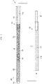
FIG. 1 is an overall view of an implant device according to an embodiment. -
FIG. 2 is a cross-sectional view of a part of the implant device. -
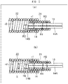
FIG. 3(a) is an explanatory diagram of the dimensions of a first wire, a second wire, a connection coil body, and an implant coil body, andFIG. 3(b) is an explanatory diagram of the relationship between the dimensions of the first wire, the second wire, and the connection coil body. -
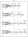
FIG. 4 is an explanatory diagram of a method of separating an implant portion from a delivery wire. - Hereinafter, an implant device according to an embodiment of the present disclosure will be described with reference to the drawings, but the present invention is not limited only to the embodiments illustrated in the drawings. In the present disclosure, a distal end refers to an end portion of the implant device in which a distal tip is located, and a proximal end refers to an end portion on the opposite side to the distal end.
-
-
FIG. 1 is an overall view of an implant device 1 according to the present embodiment. Note that, inFIG. 1 , illustration of thecoating layer 13 has been omitted. -
FIG. 2 is a cross-sectional view of a part of the implant device 1. - As shown in
FIG. 1 , the implant device 1 includes adelivery wire 10 and animplant portion 20. - The
delivery wire 10 includes ashaft 11, adelivery coil body 12, acoating layer 13, afirst wire 14, asecond wire 15, athird wire 16, and anoperation shaft 17. - The
shaft 11 is a long, linear (wire-like) member having flexibility, and has a hollow shape in which aninner cavity 11a is formed that passes through from the proximal end to the distal end. A reduceddiameter portion 11B whose outer diameter is reduced is provided in the distal end portion of theshaft 11. The proximal end portion of theshaft 11 functions as a grip portion which is gripped by an operator. - The material forming the
shaft 11 is not particularly limited as long it is a material having a level of flexibility that enables it to easily follow the curvature of the lumen inside the body (such as a blood vessel), and stainless steel, superelastic alloy materials such as nickel-titanium alloy, and synthetic resins such as polyvinyl chloride resins, urethane resins, polyolefin resins, polyamide resins, and fluororesins can be adopted as the material. The dimension of theshaft 11 is appropriately set according to the treatment target site; for example, when used for treatment of a cerebral aneurysm, the total length is set to about 100 to 2000 mm, and the outer diameter is set to about 0.2 to 2 mm. - The
delivery coil body 12 is provided on the distal end side of theshaft 11. Thedelivery coil body 12 is formed by spirally winding one or more wires so that adjacent wires make close contact with each other, and has a hollow shape having aninner cavity 12a that passes through from the proximal end to the distal end. The proximal end of thedelivery coil body 12 is joined to astepped surface 11C of theshaft 11. The reduceddiameter portion 11B of theshaft 11 is inserted into aproximal end portion 12B of thedelivery coil body 12. Thedelivery coil body 12 has atapered portion 12C on the distal end side of theproximal end portion 12B, and adistal end portion 12D having a substantially constant outer diameter on the distal end side of thetapered portion 12C. - The material forming the
delivery coil body 12 is not particularly limited as long it is a material having a level of flexibility that enables it to easily follow the curvature of the lumen inside the body (such as a blood vessel), and stainless steel, superelastic alloy materials such as nickel-titanium alloy, and radiopaque metals such as platinum and tungsten can be adopted as the material. The dimensions of thedelivery coil body 12 are appropriately set according to the treatment target site; for example, when used for treatment of a cerebral aneurysm, the total length is set to 0.5 to 200 mm, and the outer diameter is set to about 0.3 to 2 mm. Furthermore, the diameter of the wires constituting thedelivery coil body 12 is about 0.01 to 0.1 mm. - The
coating layer 13 covers the entire outer peripheral surface of thedelivery coil body 12. Thecoating layer 13 is, for example, a heat shrink tube, and examples of the resin constituting thecoating layer 13 include biocompatible resin materials such as polyamide resins and fluororesins, and hydrophilic coating materials. - The
first wire 14 has asmall diameter portion 14A and alarge diameter portion 14B. Thesmall diameter portion 14A has a substantially constant first outer diameter R1 (FIG. 3 ) from the proximal end to the distal end. The proximal end of thesmall diameter portion 14A is located on the inside of thedelivery coil body 12 and joined to thestepped surface 11C of theshaft 11, and thesmall diameter portion 14A extends from thestepped surface 11C of theshaft 11 through theinner cavity 12a of thedelivery coil body 12 toward the distal end. The proximal end portion of thesmall diameter portion 14A is joined to the outer peripheral surface of the reduceddiameter portion 11B of theshaft 11 and the inner peripheral surface of thedelivery coil body 12. As a result, thefirst wire 14, theshaft 11, and thedelivery coil body 12 are integrated. The distal end portion of thesmall diameter portion 14A protrudes from theinner cavity 12a of thedelivery coil body 12. That is to say, thesmall diameter portion 14A is configured to be longer than thedelivery coil body 12. - The
large diameter portion 14B is connected to the distal end of thesmall diameter portion 14A, and has a second outer diameter R2 (FIG. 3 ) that is larger than the first outer diameter R1. Thelarge diameter portion 14B is located on the outside of thedelivery coil body 12. As shown inFIG. 2 , when thedelivery wire 10 and theimplant portion 20 are connected, the distal end portion of thefirst wire 14 passes through aconnection coil body 21 described below, and thelarge diameter portion 14B is located inside aninner cavity 22a of animplant coil body 22 described below. The total length of thefirst wire 14 is, for example, about 0.5 to 200 mm, the outer diameter of thesmall diameter portion 14A is, for example, about 0.1 to 0.5 mm, and the outer diameter of thelarge diameter portion 14B is, for example, about 0.1 to 1 mm. - The shape of the
large diameter portion 14B is a ball shape in the present embodiment, but may be any other shape. The outer diameter of thelarge diameter portion 14B is the maximum length in a direction perpendicular to an axial direction of thefirst wire 14 in a cross-section taken in a direction perpendicular to the axial direction of thefirst wire 14. According to this definition of the outer diameter, it is possible to identify the maximum length and determine the outer diameter of thelarge diameter portion 14B, even when thelarge diameter portion 14B is, for example, disc-shaped, a long spherical shape, or cone-shaped. - The
second wire 15 includes awire portion 15A, a proximal endside bulging portion 15B, and a distal endside bulging portion 15C. Thewire portion 15A has a substantially constant third outer diameter R3 (FIG. 3 ) from the proximal end to the distal end. The proximal endside bulging portion 15B is provided on the proximal end of thewire portion 15A, and has an outer diameter which is larger than the third outer diameter R3. The distal endside bulging portion 15C is provided at a position of thewire portion 15A which is a predetermined distance on the distal end side from the proximal endside bulging portion 15B. The distal endside bulging portion 15C has an outer diameter which is larger than the third outer diameter R3. - As shown in
FIG. 2 , when thedelivery wire 10 and theimplant portion 20 are connected, the distal end portion of thesecond wire 15 is inserted inside theconnection coil body 21 described below. The total length of thesecond wire 15 is for example, about 0.5 to 200 mm, and the outer diameter is, for example, about 0.1 to 1 mm. - The
third wire 16 includes aconnection portion 16A and awire portion 16B. Theconnection portion 16A has a substantially annular shape, and is attached to the outer periphery of thewire portion 15A between the proximal endside bulging portion 15B and the distal endside bulging portion 15C of thesecond wire 15. The inner diameter of theconnection portion 16A is larger than the outer diameter of thewire portion 15A of thesecond wire 15, and smaller than the outer diameter of the proximal endside bulging portion 15B and the distal endside bulging portion 15C. As a result, theconnection portion 16A is configured to be capable of sliding a predetermined distance along the long axis direction of thewire portion 15A of thesecond wire 15 without being released from thewire portion 15A of thesecond wire 15. The predetermined distance is, for example, about 0.5 to 200 mm. - The
wire portion 16B has a substantially constant outer diameter from the proximal end to the distal end, has the proximal end connected to theoperation shaft 17 described below, extends from theoperation shaft 17 toward the earlier application side inside theinner cavity 11a of theshaft 11 and theinner cavity 12a of thedelivery coil body 12, and the distal end of thewire portion 16B is connected to theconnection portion 16A. Thethird wire 16 has theconnection portion 16A attached to the outer periphery of thewire portion 15A of thesecond wire 15, and therefore, thethird wire 16 is capable of moving a predetermined distance relative to thesecond wire 15 along the long axis direction of thesecond wire 15. The total length of thethird wire 16 is for example, about 100 to 200 mm, and the outer diameter is, for example, about 0.1 to 1.0 mm. - As examples of the material forming the
first wire 14, thesecond wire 15, and thethird wire 16, stainless steel, superelastic alloy materials such as nickel-titanium alloy, and radiopaque metals such as platinum and tungsten can be adopted. - The
operation shaft 17 has a substantially cylindrical shape, and the distal end portion of theoperation shaft 17 is inserted into theshaft 11 from the proximal end side of theinner cavity 11a of theshaft 11. Theoperation shaft 17 is slidable and movable with respect to theshaft 11. Thethird wire 16 is connected to theoperation shaft 17. Therefore, by moving theoperation shaft 17 with respect to theshaft 11 in the long axis direction, thethird wire 16 also moves along the long axis direction. As examples of the material constituting theoperation shaft 17, the same materials as those constituting theshaft 11 may be adopted. - The
implant portion 20 includes aconnection coil body 21, animplant coil body 22, and a distal end portion 23. - The
connection coil body 21 is formed by spirally winding one or more wires so that adjacent wires make close contact with each other, and has a hollow shape having aninner cavity 21a with a first inner diameter r1 (FIG. 3 ) that passes through from the proximal end to the distal end. As shown inFIG. 2 , when thedelivery wire 10 and theimplant portion 20 are connected, the proximal end portion of theconnection coil body 21 is inserted into theinner cavity 12a of thedelivery coil body 12. Note that the proximal end portion of theconnection coil body 21 is not joined to thedelivery coil body 12, and theconnection coil body 21 is separable from thedelivery coil body 12. Theconnection coil body 21 corresponds to the first coil body. - The dimensions of the
connection coil body 21 are appropriately set according to the treatment target site; for example, when used for treatment of a cerebral aneurysm, the total length is set to about 0.5 to 100 mm, and the inner diameter (first inner diameter r1) is set to about 0.2 to 1 mm. Furthermore, the diameter of the wires constituting theconnection coil body 21 is about 0.01 to 0.1 mm. - The
implant coil body 22 is formed by spirally winding one or more wires so that adjacent wires make close contact with each other, and has a hollow shape having aninner cavity 22a with a second inner diameter r2 (FIG. 3 ) that passes through from the proximal end to the distal end. Theimplant coil body 22 is disposed from the distal end portion of theconnection coil body 21 toward the distal end direction. The distal end portion of theconnection coil body 21 is inserted and joined to the proximal end portion of theimplant coil body 22. Theimplant coil body 22 corresponds to the second coil body. - The dimensions of the
implant coil body 22 are appropriately set according to the treatment target site; for example, when used for treatment of a cerebral aneurysm, the total length is set to about 10 to 500 mm, and the inner diameter (second inner diameter r2) is set to about 0.4 to 2 mm. Furthermore, the diameter of the wires constituting theimplant coil body 22 is about 0.01 to 0.1 mm. - The distal end portion 23 is substantially ball-shaped, and is joined to the distal end of the
implant coil body 22 so as to block the opening of the distal end of theimplant coil body 22. The outer diameter of the distal end portion 23 is the same or slightly smaller than the outer diameter of theimplant coil body 22. As examples of the material forming theconnection coil body 21, theimplant coil body 22, and the distal end portion 23, radiopaque metals such as platinum, gold, tungsten, and alloys of these metals can be adopted. - The wires constituting the
delivery coil body 12, theconnection coil body 21, and theimplant coil body 22 may be a single wire or a twisted wire in which a plurality of single wires are twisted together. - Next, the relationship between the dimensions of the
first wire 14, thesecond wire 15, theconnection coil body 21, and theimplant coil body 22 will be described. -
FIG. 3(a) is an explanatory diagram of the dimensions of thefirst wire 14, thesecond wire 15, theconnection coil body 21, and theimplant coil body 22, andFIG. 3(b) is an explanatory diagram of the relationship between the dimensions of thefirst wire 14, thesecond wire 15, and theconnection coil body 21. - As shown in
FIG. 3(a) , thesmall diameter portion 14A of thefirst wire 14 has the first outer diameter R1, thelarge diameter portion 14B of thefirst wire 14 has the second outer diameter R2, thesecond wire 15 has the third outer diameter R3, theconnection coil body 21 has the first inner diameter r1, and theimplant coil body 22 has the second inner diameter r2. - Further, the
first wire 14, thesecond wire 15, and theconnection coil body 21 are configured such that the first outer diameter R1 of thesmall diameter portion 14A, the second outer diameter R2 of thelarge diameter portion 14B, the third outer diameter R3 of thesecond wire 15, and the first inner diameter r1 of theconnection coil body 21 satisfy equations (1) and (2) below.

- The term [(R1+R2)/2+R3] in equation (1) corresponds to a maximum width X of the
first wire 14 and thesecond wire 15 when thefirst wire 14 and thesecond wire 15 are viewed from the distal end side in a state where thesmall diameter portion 14A of thefirst wire 14 and thesecond wire 15 are in contact with each other as shown inFIG. 3(b) , Because the relationship (R1+R2)/2+R3 > r1 shown in equation (1) is satisfied, thefirst wire 14 and thesecond wire 15 are configured so as to not become released from theconnection coil body 21, even in a state where thesmall diameter portion 14A of thefirst wire 14 and thesecond wire 15 are in contact with each other. Because the relationship r1 > R1+R3 shown in equation (1) is satisfied, both thesmall diameter portion 14A of thefirst wire 14 and thesecond wire 15 can be simultaneously inserted into theconnection coil body 21. - Further, because the relationship r1 > R2 shown in equation (2) is satisfied, the
first wire 14 can be released from theconnection coil body 21 after thesecond wire 15 is released from theconnection coil body 21. - Furthermore, the
first wire 14, thesecond wire 15, and theimplant coil body 22 are configured such that the second outer diameter R2 of thelarge diameter portion 14B, the third outer diameter R3 of thesecond wire 15, and the second inner diameter r2 of theimplant coil body 22 satisfy equation (3) below.
- Because the second inner diameter r2, the first outer diameter R1, the second outer diameter R2, and the third outer diameter R3 satisfy the relationship shown in equation (3), the
small diameter portion 14A of thefirst wire 14 and thesecond wire 15 can be simultaneously inserted into theconnection coil body 21 inside theimplant coil body 22. - Next, a method of separating the
implant portion 20 from thedelivery wire 10 in the implant device 1 of the present embodiment will be described with reference toFIG. 4 . -
FIG. 4 is an explanatory diagram of a method of separating theimplant portion 20 from thedelivery wire 10. InFIG. 4 , the illustration of thedelivery coil body 12 and thecoating layer 13 is omitted. - The
operation shaft 17 shown inFIG. 1 is positioned in theshaft 11 at the most distal end of the range of possible movement, and as shown inFIG. 4(a) , the distal endside bulging portion 15C of thesecond wire 15 is pushed by theconnection portion 16A of thethird wire 16 so as to advance the implant device 1 inside the blood vessel in a state where thewire portion 15A of thesecond wire 15 is located inside theconnection coil body 21, which causes theimplant coil body 22 to be inserted into the target site (such as a cerebral aneurysm). - Then, the
operation shaft 17 is pulled so as to move thethird wire 16 by a predetermined distance toward the proximal end side with respect to thesecond wire 15, and as shown inFIG. 4(b) , theconnection portion 16A of thethird wire 16 is brought into contact with the proximal endside bulging portion 15B of thesecond wire 15. Further, as shown inFIG. 4(c) , by pulling theoperation shaft 17, thesecond wire 15 is also pulled via thethird wire 16, and thesecond wire 15 becomes released from theconnection coil body 21. - Finally, by pulling the
shaft 11 toward the proximal end side, thefirst wire 14 is also pulled such that, as shown inFIG. 4(d) , thefirst wire 14 is released from theconnection coil body 21. As a result, theimplant portion 20 is separated from thedelivery wire 10, and theimplant portion 20 is placed in the target site. - As described above, according to the implant device 1 of the present disclosure, the first outer diameter R1 of the
small diameter portion 14A, the second outer diameter R2 of thelarge diameter portion 14B, the third outer diameter R3 of thesecond wire 15, and the first inner diameter r1 of theconnection coil body 21 are configured so as to satisfy the relationships of equation (1) and equation (2) above. With this configuration, thesmall diameter portion 14A of thefirst wire 14 and thesecond wire 15 can be simultaneously inserted into theconnection coil body 21, and thefirst wire 14 and thesecond wire 15 can be prevented from being released from theconnection coil body 21, even in a state where thesmall diameter portion 14A of thefirst wire 14 and thesecond wire 15 are in contact with each other. Further, thefirst wire 14 can be released from theconnection coil body 21 after thesecond wire 15 is released from theconnection coil body 21. As a result, it is possible to suppress force from acting on theimplant portion 20 when the implant portion 20 (theconnection coil body 21 and the implant coil body 22) is separated from the delivery wire 10 (thefirst wire 14, thesecond wire 15, and the third wire 16), and therefore, theimplant portion 20 can be stably placed within a blood vessel to perform embolization. - The implant device 1 includes the
third wire 16, which is located on the proximal end side of thesecond wire 15, is connected to thesecond wire 15, and is capable of moving a predetermined distance relative to thesecond wire 15 along the long axis direction of thesecond wire 15. Therefore, when the implant device 1 is inserted inside a blood vessel, thesecond wire 15 can be prevented from being released from theconnection coil body 21, even when thethird wire 16 moves toward the proximal end side with respect to thesecond wire 15. - Furthermore, because the second outer diameter R2, the third outer diameter R3, and the second inner diameter r2 are configured so as to satisfy equation (3), the
small diameter portion 14A of thefirst wire 14 and thesecond wire 15 can be simultaneously inserted into theconnection coil body 21 inside theimplant coil body 22. - Note that the present disclosure is not limited to the configurations of the embodiments described above, but is stipulated by the claims, and the present disclosure is intended to include all modifications within the meaning and scope equivalent to the claims.
-
- 1: Implant device
- 10: Delivery wire
- 11: Shaft
- 11a: Inner cavity
- 11B: Reduced diameter portion
- 11C: Stepped surface
- 12: Delivery coil body
- 12a: Inner cavity
- 12B: Proximal end portion
- 12C: Tapered portion
- 12D: Distal end portion
- 13: Coating layer
- 14: First wire
- 14A: Small diameter portion
- 14B: Large diameter portion
- 15: Second wire
- 15A: Wire portion
- 15B: Proximal end side bulging portion
- 15C: Distal end side bulging portion
- 16: Third wire
- 16A: Connection portion
- 16B: Wire portion
- 17: Operation shaft
- 20: Implant portion
- 21: Connection coil body
- 21a: Inner cavity
- 22: Implant coil body
- 22a: Inner cavity
- r1: First inner diameter
- r2: Second inner diameter
- R1: First outer diameter
- R2: Second outer diameter
- R3: Third outer diameter
Claims (3)
- An implant device, comprising:a first coil body having an inner cavity with a first inner diameter r1 that passes through from a proximal end to a distal end;a second coil body arranged more toward a distal end direction of the implant device than a distal end portion of the first coil body, and having a second inner diameter r2;a first wire having a small diameter portion having a first outer diameter R1, and a large diameter portion connected to the small diameter portion, and having a second outer diameter R2 that is larger than the first outer diameter R1; anda second wire having a third outer diameter R3; whereinthe small diameter portion of the first wire and the second wire can be simultaneously inserted into the inner cavity of the first coil body, andthe first outer diameter R1, the second outer diameter R2, the third outer diameter R3, and the first inner diameter r1 satisfy equation (1): (R1+R2)/2+R3 > r1 > R1+R3, and equation (2): r1 > R2.
- The implant device according to claim 1, further comprising
a third wire located on the proximal end side of the second wire, which is connected to the second wire, and is capable of moving a predetermined distance along a long axis direction of the second wire. - The implant device according to claim 1 or 2, wherein the second outer diameter R2, the third outer diameter R3, and the second inner diameter r2 satisfy equation (3): r2 > (R1+R2)/2+R3.
Applications Claiming Priority (2)
| Application Number | Priority Date | Filing Date | Title |
|---|---|---|---|
| JP2019132985A JP2021016485A (en) | 2019-07-18 | 2019-07-18 | Implant device |
| PCT/JP2020/026491 WO2021010222A1 (en) | 2019-07-18 | 2020-07-06 | Implant device |
Publications (1)
| Publication Number | Publication Date |
|---|---|
| EP4000539A1 true EP4000539A1 (en) | 2022-05-25 |
Family
ID=74210515
Family Applications (1)
| Application Number | Title | Priority Date | Filing Date |
|---|---|---|---|
| EP20841266.8A Withdrawn EP4000539A1 (en) | 2019-07-18 | 2020-07-06 | Implant device |
Country Status (5)
| Country | Link |
|---|---|
| US (1) | US20220133328A1 (en) |
| EP (1) | EP4000539A1 (en) |
| JP (1) | JP2021016485A (en) |
| CN (1) | CN114126511A (en) |
| WO (1) | WO2021010222A1 (en) |
Families Citing this family (2)
| Publication number | Priority date | Publication date | Assignee | Title |
|---|---|---|---|---|
| JP2022132760A (en) * | 2021-03-01 | 2022-09-13 | 朝日インテック株式会社 | delivery system |
| WO2022201226A1 (en) * | 2021-03-22 | 2022-09-29 | 朝日インテック株式会社 | Embolic coil and delivery system |
Family Cites Families (10)
| Publication number | Priority date | Publication date | Assignee | Title |
|---|---|---|---|---|
| US5578074A (en) * | 1994-12-22 | 1996-11-26 | Target Therapeutics, Inc. | Implant delivery method and assembly |
| FR2772592B1 (en) * | 1997-12-19 | 2000-04-07 | Braun Celsa Sa | ASSEMBLY FOR THE PLACEMENT OF AN IMPLANT IN AN INTERNAL CONDUIT OF A BODY |
| WO2008109557A1 (en) * | 2007-03-02 | 2008-09-12 | Marvell World Trade Ltd. | Dynamic image dithering |
| CA2681663A1 (en) * | 2007-04-12 | 2008-10-23 | Boston Scientific Limited | Instantaneous mechanical detachment mechanism for vaso-occlusive devices |
| EP2941296B1 (en) * | 2013-01-03 | 2019-05-15 | Donald K. Jones | Detachable coil release system and handle assembly |
| WO2014145012A2 (en) * | 2013-03-15 | 2014-09-18 | Covidien Lp | Delivery and detachment mechanisms for vascular implants |
| US11291452B2 (en) * | 2013-06-26 | 2022-04-05 | W. L. Gore & Associates, Inc. | Medical device deployment system |
| US9918718B2 (en) * | 2014-08-08 | 2018-03-20 | DePuy Synthes Products, Inc. | Embolic coil delivery system with retractable mechanical release mechanism |
| JP5948535B1 (en) * | 2015-05-29 | 2016-07-06 | 株式会社エフエムディ | Medical guidewire |
| US11051822B2 (en) * | 2016-06-28 | 2021-07-06 | Covidien Lp | Implant detachment with thermal activation |
-
2019
- 2019-07-18 JP JP2019132985A patent/JP2021016485A/en not_active Withdrawn
-
2020
- 2020-07-06 CN CN202080051462.XA patent/CN114126511A/en not_active Withdrawn
- 2020-07-06 EP EP20841266.8A patent/EP4000539A1/en not_active Withdrawn
- 2020-07-06 WO PCT/JP2020/026491 patent/WO2021010222A1/en not_active Ceased
-
2022
- 2022-01-14 US US17/576,473 patent/US20220133328A1/en not_active Abandoned
Also Published As
| Publication number | Publication date |
|---|---|
| US20220133328A1 (en) | 2022-05-05 |
| CN114126511A (en) | 2022-03-01 |
| WO2021010222A1 (en) | 2021-01-21 |
| JP2021016485A (en) | 2021-02-15 |
Similar Documents
| Publication | Publication Date | Title |
|---|---|---|
| US9937069B2 (en) | Pusher guide wire and delivery system comprising the same | |
| EP2417999B1 (en) | Guidewire with bent portion fixed with a fixing member | |
| EP3011938B1 (en) | Pusher guide wire | |
| EP2163276A1 (en) | Guide wire | |
| US20200016387A1 (en) | Dilator | |
| EP2338556A2 (en) | Guidewire | |
| EP2749314A1 (en) | Guidewire | |
| US20220133328A1 (en) | Implant device | |
| CN110193130B (en) | Guide wire | |
| EP3662954A1 (en) | Catheter | |
| US20210145465A1 (en) | Catheter | |
| EP3025752A1 (en) | Catheter | |
| JP2008099877A (en) | Stent delivery system | |
| US20230321409A1 (en) | Guide wire | |
| CN114668954B (en) | Guide wire | |
| JP7532573B2 (en) | Guidewires | |
| EP3298973B1 (en) | Endoscopic treatment instrument | |
| WO2019234797A1 (en) | Catheter | |
| EP4360688A1 (en) | Guide wire | |
| JP7548851B2 (en) | Delivery System | |
| EP3995169A1 (en) | Catheter | |
| US11931535B2 (en) | Guide wire | |
| JP7290451B2 (en) | guide wire | |
| WO2021255934A1 (en) | Delivery system | |
| JP2024027763A (en) | Medical long body |
Legal Events
| Date | Code | Title | Description |
|---|---|---|---|
| STAA | Information on the status of an ep patent application or granted ep patent |
Free format text: STATUS: THE INTERNATIONAL PUBLICATION HAS BEEN MADE |
|
| PUAI | Public reference made under article 153(3) epc to a published international application that has entered the european phase |
Free format text: ORIGINAL CODE: 0009012 |
|
| STAA | Information on the status of an ep patent application or granted ep patent |
Free format text: STATUS: REQUEST FOR EXAMINATION WAS MADE |
|
| 17P | Request for examination filed |
Effective date: 20220201 |
|
| AK | Designated contracting states |
Kind code of ref document: A1 Designated state(s): AL AT BE BG CH CY CZ DE DK EE ES FI FR GB GR HR HU IE IS IT LI LT LU LV MC MK MT NL NO PL PT RO RS SE SI SK SM TR |
|
| DAV | Request for validation of the european patent (deleted) | ||
| DAX | Request for extension of the european patent (deleted) | ||
| STAA | Information on the status of an ep patent application or granted ep patent |
Free format text: STATUS: THE APPLICATION HAS BEEN WITHDRAWN |
|
| 18W | Application withdrawn |
Effective date: 20221020 |