EP4000474A1 - Telescopic drinking straw - Google Patents
Telescopic drinking straw Download PDFInfo
- Publication number
- EP4000474A1 EP4000474A1 EP20207512.3A EP20207512A EP4000474A1 EP 4000474 A1 EP4000474 A1 EP 4000474A1 EP 20207512 A EP20207512 A EP 20207512A EP 4000474 A1 EP4000474 A1 EP 4000474A1
- Authority
- EP
- European Patent Office
- Prior art keywords
- straw
- locking elements
- paper
- telescopic
- locking
- Prior art date
- Legal status (The legal status is an assumption and is not a legal conclusion. Google has not performed a legal analysis and makes no representation as to the accuracy of the status listed.)
- Granted
Links
Images




Classifications
-
- A—HUMAN NECESSITIES
- A47—FURNITURE; DOMESTIC ARTICLES OR APPLIANCES; COFFEE MILLS; SPICE MILLS; SUCTION CLEANERS IN GENERAL
- A47G—HOUSEHOLD OR TABLE EQUIPMENT
- A47G21/00—Table-ware
- A47G21/18—Drinking straws or the like
- A47G21/189—Drinking straws or the like telescoping
Definitions
- the object of the invention is a telescopic paper drinking straw.
- the invention relates to beverage drinking straws, in particular telescopic straws made of biodegradable materials such as paper.
- straws which are usually made of plastic and pose a serious threat to ecosystems due to their long decay period of up to 200 years are used to drink various kinds of beverages. These may be both one-part and two-part straws, straight straws or bent straws.
- Plastic straws are made as one straight element or as an element having an articulated part allowing to bend it.
- Two-part straws usually have in their structure a lock connecting both parts so that after inserting one part into the other a beverage may be consumed with an already assembled straw without a fear that the connection will be leaky.
- Such connection allows taking a straw off, for example before wrapping the straw into a foil from which the straw is removed before consuming a beverage and which is unfolded to its maximum length.
- Such straws are referred to as telescopic straws.
- Telescopic drinking straws in particular made of plastic materials, are known in the prior art.
- a telescopic drinking straw provided with an outer straw and an inner straw.
- the inner straw has an extended part at the base, while the outer straw is narrowed at its tip. Transitions between the diameters are in both cases gradual so that the straws have a conical shape.
- the outer straw is provided with a part having a slightly reduced diameter
- the inner straw is provided with a part having a slightly increased diameter so that in an unfolded configuration the part with increased diameter of the inner straw overlaps the part with reduced diameter of the outer straw.
- the publication DE20309272U1 disclosed a telescopic straw provided with an outer straw with embossing directed to the inside of the outer straw and an inner straw provided with embossing directed to the inside of the inner straw. Due to the corresponding shape of the embossing, the embossing of the outer straw adapts to the embossing in the inner straw and fixes the inner straw inside the outer straw.
- the object of the invention is a telescopic paper drinking straw comprising: a first straw with a first outer diameter, a second straw with a second inner diameter, whereas the straw with the first outer diameter is situated at least partly inside the straw with the second inner diameter, coaxially with the straw with the second inner diameter.
- the straw according to the invention is characterised in that the first straw has at least two locking elements protruding from the outer surface of the first straw, and the second straw has at least two locking elements protruding from the inner surface of the second straw.
- the paper straw according to the invention is characterised in that at least two locking elements protruding from the inner surface of the second straw are arranged at a distance of at least half the diameter of the first straw.
- the paper straw according to the invention is characterised in that at least two locking elements protruding from the outer surface of the first straw are arranged at a distance of at least half the diameter of the first straw.
- the paper straw according to the invention is characterised in that the distance between the first and second locking elements on the first and second straw, respectively, is at least 2 mm.
- the paper straw according to the invention is characterised in that the locking elements have the form of ring-shaped embosses.
- the paper straw according to the invention is characterised in that the locking elements have different height or width.
- the paper straw according to the invention is characterised in that the locking elements are adapted to form a seal of a telescopic joint.
- the paper straw according to the invention is characterised in that at least one locking element on the first straw is situated at a distance of at least half the diameter of the first straw from one of its ends.
- the paper straw according to the invention is characterised in that at least one locking element on the second straw is situated at a distance of at least half the diameter of the second straw from one of its ends.
- the paper straw according to the invention is characterised in that the inner diameter of the second straw at one end is smaller than the outer diameter of the first straw.
- the paper straw according to the invention is characterised in that at least two locking elements of the first straw and at least two locking elements of the second straw are arranged at a distance corresponding to the diameter of the first straw.
- the paper straw according to the invention is characterised in that the distance between the locking elements of the first straw is greater than the width of the locking element of the second straw, and the distance between the locking elements of the second straw is greater than the width of the locking element of the first straw.
- the paper straw according to the invention is characterised by having two configurations, whereas in the first configuration the first straw is substantially inside the second straw, and a part of the first straw protrudes from the second straw allowing pulling the first straw out of the second straw, while in the second configuration the first straw is substantially pulled out of the second straw so that at least one locking element of the first straw is situated between the locking elements of the second straw, or at least one locking element of the second straw is situated between the locking elements of the first straw.
- the paper straw according to the invention is characterised in that in the second configuration, in the first working position, one of the locking elements of the first straw is situated between the locking elements of the second straw, and in the second working position the second locking element of the first straw is situated between the locking elements of the second straw.
- the paper straw according to the invention is characterised in that, in the second configuration, the lateral surface of at least one locking element of the first straw protruding from the external surface of the first straw is in contact with the lateral surface of at least one element protruding from the internal surface of the second straw.
- An advantage of the paper telescopic straw is its biodegradability. Moreover, advantageous features of the telescopic joint ensure that the telescopic straw maintains its axial stability in the unfolded configuration. Another advantage of the telescopic straw according to the invention is that during unfolding the user clearly feels the moment when the first locking elements squeeze through and may easily stop the unfolding movement, at the same time retaining the possibility to unfold the straw completely if necessary. Moreover, the straw according to the invention minimizes the material consumption while maintaining the axial stability, and also improves the safety of use because in case of an accident the straw folds to minimum dimensions.
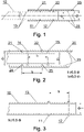
- Fig. 1 shows the first embodiment of a telescopic paper straw according to the invention.
- the telescopic straw substantially comprises a first straw 10 with a first outer diameter d 1 and a second straw 20 with a second inner diameter d 2 .
- the straw 10 is situated coaxially with the straw 20 having the second diameter and at least partly inside the straw 20. A part of the straw 10 protrudes out of the straw 20 to facilitate pulling the first straw 10 out of the second straw 20.
- the first straw 10 has at least two locking elements 11, 12 protruding from its outer surface 13, while the second straw 20 has at least two locking elements 21, 22 protruding inwards from its inner surface 23.
- Fig. 1 the straw according to the first embodiment of the invention was shown in an extended configuration in one of the working positions.
- the straws 10 and 20 are spiral straws made of at least two paper bands, preferably of three paper bands, joined by means of an appropriate adhesive suitable for food applications. Such straws are biodegradable and do not permanently contaminate the environment.
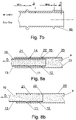
- Fig. 2 shows the second straw 20 and an outline of the first straw 10, in addition, locking elements 21 and 22 situated on the second straw 20 and protruding from the inner surface 23 of the straw 20 are clearly shown.
- the locking elements 21, 22 have the form of circumferential embosses directed towards the inside of the second straw 20.
- the paper of which the straw is made is a material of cellulose fibres, it is susceptible to shaping, e.g. extrusion or embossing, whereas it retains a certain degree of elasticity, which has an advantageous effect on the sealing properties of the telescopic joint.
- the contact points 14, 15, 24, 25 are formed by contacts of the locking elements 11, 12 of the first straw with the inner surface 23 of the second straw 20 and by contacts of the locking elements 21, 22 of the second straw 20 with the outer surface 13 of the first straw 10.
- advantageous effects of axial stabilisation may be observed already for 2 mm spacing of the locking elements 21 and 22 on the straw 20, whereas in this case the straw 20 has an inner diameter of approx. 4 mm.
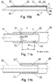
- Fig. 3 shows the first straw 10 which is provided with the first locking elements 11 and the second locking elements 12 protruding from the outer surface 13 of the straw 10.
- the straw 10 works with the straw 20, therefore the arrangement of the locking elements on the straw 10 should substantially correspond to the arrangement of the locking elements on the straw 20.
- the locking elements 11 and 12 are arranged at a distance I 1 of at least half the diameter d 1 of the straw 10. It corresponds to the arrangement of the locking elements 21, 22 on the straw 20.
- Fig. 4 shows the first straw 10 in an isometric view, in particular the shape of the locking elements 11, 12 is shown.
- the locking elements 11 and 12 have the shape of embosses made substantially on the whole circumference of the straw 10.
- the locking elements 11 and 12 may have the form of embosses due to the use of paper as the material of which the telescopic straw is made.
- the paper as a material composed of fibres, is susceptible to embossing.
- FIG. 5a shows contact points 14, 15 of the locking elements 11,12 of the first straw 10 with the inner surface 23 of the second straw 20. Since in this embodiment the locking elements 11, 12 are substantially identical and form the same contact points, they were marked in the figure as the same element.
- the tightness of connection between the straws 10 and 20 is ensured by the elasticity of the material of the locking elements 11, 12 which impact the inner surface 23 of the straw 20 with their top part 16, 17 by forming the contact points 14, 15.
- a similar situation occurs in the case of the connection between the straws 10 and 20 shown in Fig. 5b .
- the top parts 26, 27 of the locking elements 21, 22 of the straw 20 form the contact points 24, 25 with the outer surface 13 of the straw 10 which ensure the support and the stability as well as the tightness of the joint.
- Figs. 6A and 6B show the first straw 10 and the second straw 20, respectively, together with the corresponding locking elements 11', 12' and 21', 22'.
- the locking elements 11' and 12' have different heights h 11 and h 12
- the locking elements 21' and 22' have different heights h 21 and h 22 , respectively.
- h 11 >h 12 , and h 21 >h 22 in another embodiment not shown in the figures, the relationship of heights of the locking elements is opposite, and h 11 ⁇ h 12 , and h 21 ⁇ h 22 .
- Fig. 6c shows a joint of the straws 10 and 20 having the locking elements 11', 12' and 21', 22', respectively.
- the first contact point 24 is formed at the point of contact of the top part 26 of the locking element 21' of the straw 20 with the outer surface 13 of the straw 10.
- the second contact point 14 is formed at the point of contact of the top part 16 of the locking element 11' of the straw 10 with the inner surface 23 of the straw 20.
- the contact points will be at the point 15' for the locking element 12', respectively, whereas the contact point 16' is formed at the point of contact of the top lateral part 17' with the top lateral part 27' of the locking element 22'.
- the locking elements 12" and 22' in this embodiment act more as a threshold informing the user, pulling the straw 10 out of the straw 20 to the working position, that the first locking element 21' has passed through the locking element 12', thus that the force used to pull the straw 10 out of the straw 20 needs to be reduced.
- Fig. 7A shows the straw 10 with the locking elements 11 and 12 having the width w 11 and w 12 , respectively, where w 11 >w 12 .
- the relationship of the width of the locking elements may be opposite, where w 11 ⁇ w 12 .
- Fig. 7B shows an embodiment wherein the straw 10 is provided with the locking elements 11 and 12 having different widths and heights, whereas h 11 >h 12 and w 11 >w 12 .
- the height and the width of the locking elements 21 and 22 formed on the straw 20 are subject to the same variability. With increasing width of the locking element, there is also an increase in the tightness of the telescopic joint and at the same time in the limiting axial force required to unfold the telescopic straw. Similar technical effects are observed when the height of the locking elements is increased.
- Fig. 8a shows the telescopic straw in the extended configuration in the first working position, filled with liquid F.
- the first working position occurs when the locking element 11 is between the locking elements 21 and 22 of the straw 20.
- the locking element 12 of the straw 10 touches the inner surface 23 of the straw 20 at the point of contact 15 and creates an airtight barrier preventing the penetration of the liquid F into the space between the locking elements 11, 12.
- An additional barrier is formed by the locking element 22 of the straw 20 which contacts the outer surface 13 of the straw 10.
- the locking elements 11 and 21 of the straws 10 and 20, respectively, form subsequent barriers preventing the penetration of the liquid F through the telescopic joint and a lock against slipping out of the straw 10 from the straw 20 when pulling the straw 10 out of the straw 20 in the direction D.
- the spacing of the locking elements 11, 12 and 21 and 22 results in a limitation of the possibility of reciprocal displacement of the straws 10 and 20.
- it increases the axial stability of the telescopic straw in the extended position, which also contributes to an increase in tightness of the joint as it limits the leakage of the liquid F through subsequent sealing barriers even if a significant force is applied to the pulled out end of the straw 10 in a direction perpendicular to its longitudinal axis, which results in the occurrence of a rotating moment having a tendency to unseal the tight barrier formed by the element 12 and also the element 22.
- Additional tight barriers are also formed by contacting lateral surfaces of the locking elements 12 and 22, as well as by contacting lateral surfaces of the locking elements 11 and 21. These additional barriers have an advantageous effect on increasing the tightness of the telescopic joint.
- the telescopic straw in Fig. 8b is in an intermediate position between the first position and the second working position in the extended configuration.
- the locking element 11 of the straw 10 has been moved behind the locking element 21 of the straw 20 when pulling the straw 10 out in the direction D, and the locking element 12 is between the locking elements 21 and 22 of the straw 20.
- the telescopic straw passes to the second working position shown in Fig. 8c .
- the locking element 12 of the straw 10 is between two locking elements 21, 22 of the outer straw 20 as in the intermediate position described above.
- the lateral surfaces of the locking elements 12 and 21 come into contact with each other and form additional tight barriers.
- the joint between the straws 10 and 20 should have at least two points of support.
- the same condition may also be fulfilled in a configuration not shown in the figure where the distance between the second locking element 12 of the straw 10 and its edge is greater than or equal to the length of the distance between the locking elements 21 and 22 of the straw 20.
- Fig. 9 shows another embodiment of the telescopic straw, in particular Fig. 9 shows the straw 10 with the locking elements 11 and 12. It should be noted that the locking element 12 is situated at a distance of I 12 from the end of the straw 10, and the straw 10 has a diameter d 1 . In the preferred embodiment, the distance I 12 is less than half the diameter of the straw 10. It is advantageous to minimise the distance I 12 due to the resulting material savings.
- the straw 20, at the end 40 without the locking elements 21, 22, has an inner diameter d 22 smaller than the outer diameter d 1 of the straw 10.
- the diameter reduction has the form of a circumferential crease 41 and prevents the straw 10 from slipping out of the straw 20 through the end 40 when the telescopic straw is in the folded configuration in which most of the straw 10 is inside the straw 20.
- Fig. 10a shows an embodiment with the crease 41 wherein the end 40 of the straw 22 without the locking elements 21, 22 has a diameter d 22 ⁇ d 1 . In the embodiment shown in Fig.
- the locking elements 11, 12 of the straw 10 are spaced at the distance I 1
- the locking elements 21, 22 of the straw 20 are spaced at the distance I 2 , where I 1 ⁇ I 2 ⁇ d 1 . It was determined through tests that advantageous spacing of the locking elements for both elements 11 and 12 and elements 21, 22 is the distance corresponding to the diameter d 1 of the straw 10. This allows achieving a compromise between ensuring the axial stability of the telescopic joint and the material consumption associated with the formation of a stabilisation area in which both straws 10 and 20 are inserted into each other when the telescopic straw is in the extended configuration.
- Fig. 10b shows another embodiment of the outer straw 20 whose end 40 has a minimum crease 41'.
- the distance I 4 corresponds to the length of the straw's 20 end section which has been creased inwards.
- the distance I 4 should extend radially inside the straw as deep as to come up at least to the inner surface of the 18 inner straw 10.
- Fig. 11a shows, in close-up, a fragment of the telescopic straw with clearly visible locking elements 11 and 12 of the straw 10 and locking elements 21, 22 of the straw 20.
- the width of the locking element 11 is marked as w 11 and the width of the locking element 22 as w 22 .
- the distance between the locking elements 11 and 12 is marked as I 1 and the distance between the locking elements 21 and 22 as I 2 .
- the distance I 1 is greater than the width w 11
- the distance I 2 is greater than the width w 22 .
- Fig. 11b shows the locking element 21" as a locking element formed at the end of the straw 20 as a crease or a collar, which allows using to the maximum the material of which the telescopic straw is made.
- Fig. 12a shows the telescopic straw in the first configuration, i.e. in the folded (or transport) configuration.
- the telescopic straw In this configuration, most of the straw 10 is situated inside the straw 20 and is held inside the straw by the crease 41 of the free end of the straw 40, i.e. the end at which the locking elements 21, 22 were not formed.
- the telescopic straw In the folded configuration, the telescopic straw has a smaller overall length. It is also the configuration in which the telescopic straw is attached to the package of e.g. a beverage.
- Fig. 12b shows the telescopic straw in the second configuration in the first working position.
- the straw 10 is pulled out of the straw 20 so that the locking elements 11 have been pushed through the locking elements 22 and are in the area between the locking elements 21 and 22.
- the lateral surfaces of the locking elements 11 and 21 and the locking elements 12 and 22 contact each other, which increases the tightness of the telescopic joint.
- Puling the straw 10 out to the first working position requires the first limiting force to be applied axially. Passing through a clamp in the form of the locking elements 22 by the locking elements 11 is clearly perceptible to the user and allows reducing the axial force with which the straw 10 is pulled out below the threshold of the first limiting force and stabilising the telescopic straw in its first working position. If the locking elements 21, 22 and 11 and 12 are placed too close to each other, the user may not be able to reduce the axial force with which the straw 10 is pulled out below the threshold of the first limiting force, which will result in the locking element 11 passing through the locking elements 21.
- the straw 10 may also be passed through the crease 41 formed at the free end 40 of the straw 20 when it is pushed into the straw 20 by applying an axial force above the second limiting force to the straw 10.
- the ability to squeeze through the creased free end of the straw 20 is an important function increasing the safety of use of the telescopic straw, e.g. in the event of a fall when drinking a beverage through the telescopic straw, the telescopic straw will fold to the minimum length and minimise possible injuries.
Landscapes
- Table Equipment (AREA)
- Packages (AREA)
Abstract
Description
- The object of the invention is a telescopic paper drinking straw.
- The invention relates to beverage drinking straws, in particular telescopic straws made of biodegradable materials such as paper.
- In the food industry, straws which are usually made of plastic and pose a serious threat to ecosystems due to their long decay period of up to 200 years are used to drink various kinds of beverages. These may be both one-part and two-part straws, straight straws or bent straws. Plastic straws are made as one straight element or as an element having an articulated part allowing to bend it. Two-part straws usually have in their structure a lock connecting both parts so that after inserting one part into the other a beverage may be consumed with an already assembled straw without a fear that the connection will be leaky. Such connection allows taking a straw off, for example before wrapping the straw into a foil from which the straw is removed before consuming a beverage and which is unfolded to its maximum length. Such straws are referred to as telescopic straws.
- Telescopic drinking straws, in particular made of plastic materials, are known in the prior art.
- From the document
EP0139074A is known a telescopic drinking straw provided with an outer straw and an inner straw. The inner straw has an extended part at the base, while the outer straw is narrowed at its tip. Transitions between the diameters are in both cases gradual so that the straws have a conical shape. The outer straw is provided with a part having a slightly reduced diameter, and the inner straw is provided with a part having a slightly increased diameter so that in an unfolded configuration the part with increased diameter of the inner straw overlaps the part with reduced diameter of the outer straw. - The publication
DE20309272U1 disclosed a telescopic straw provided with an outer straw with embossing directed to the inside of the outer straw and an inner straw provided with embossing directed to the inside of the inner straw. Due to the corresponding shape of the embossing, the embossing of the outer straw adapts to the embossing in the inner straw and fixes the inner straw inside the outer straw. - In the publication
US4657182 is disclosed a telescopic straw in which the inner straw is provided with an extension at one end, and the outer straw is successively clamped on the inner straw to form a unit preventing the inner straw from sliding out. - The object of the invention is a telescopic paper drinking straw comprising: a first straw with a first outer diameter, a second straw with a second inner diameter, whereas the straw with the first outer diameter is situated at least partly inside the straw with the second inner diameter, coaxially with the straw with the second inner diameter. The straw according to the invention is characterised in that the first straw has at least two locking elements protruding from the outer surface of the first straw, and the second straw has at least two locking elements protruding from the inner surface of the second straw.
- The paper straw according to the invention is characterised in that at least two locking elements protruding from the inner surface of the second straw are arranged at a distance of at least half the diameter of the first straw.
- The paper straw according to the invention is characterised in that at least two locking elements protruding from the outer surface of the first straw are arranged at a distance of at least half the diameter of the first straw.
- The paper straw according to the invention is characterised in that the distance between the first and second locking elements on the first and second straw, respectively, is at least 2 mm.
- The paper straw according to the invention is characterised in that the locking elements have the form of ring-shaped embosses.
- The paper straw according to the invention is characterised in that the locking elements have different height or width.
- The paper straw according to the invention is characterised in that the locking elements are adapted to form a seal of a telescopic joint.
- The paper straw according to the invention is characterised in that at least one locking element on the first straw is situated at a distance of at least half the diameter of the first straw from one of its ends.
- The paper straw according to the invention is characterised in that at least one locking element on the second straw is situated at a distance of at least half the diameter of the second straw from one of its ends.
- The paper straw according to the invention is characterised in that the inner diameter of the second straw at one end is smaller than the outer diameter of the first straw.
- The paper straw according to the invention is characterised in that at least two locking elements of the first straw and at least two locking elements of the second straw are arranged at a distance corresponding to the diameter of the first straw.
- The paper straw according to the invention is characterised in that the distance between the locking elements of the first straw is greater than the width of the locking element of the second straw, and the distance between the locking elements of the second straw is greater than the width of the locking element of the first straw.
- The paper straw according to the invention is characterised by having two configurations, whereas in the first configuration the first straw is substantially inside the second straw, and a part of the first straw protrudes from the second straw allowing pulling the first straw out of the second straw, while in the second configuration the first straw is substantially pulled out of the second straw so that at least one locking element of the first straw is situated between the locking elements of the second straw, or at least one locking element of the second straw is situated between the locking elements of the first straw.
- The paper straw according to the invention is characterised in that in the second configuration, in the first working position, one of the locking elements of the first straw is situated between the locking elements of the second straw, and in the second working position the second locking element of the first straw is situated between the locking elements of the second straw.
- The paper straw according to the invention is characterised in that, in the second configuration, the lateral surface of at least one locking element of the first straw protruding from the external surface of the first straw is in contact with the lateral surface of at least one element protruding from the internal surface of the second straw.
- An advantage of the paper telescopic straw is its biodegradability. Moreover, advantageous features of the telescopic joint ensure that the telescopic straw maintains its axial stability in the unfolded configuration. Another advantage of the telescopic straw according to the invention is that during unfolding the user clearly feels the moment when the first locking elements squeeze through and may easily stop the unfolding movement, at the same time retaining the possibility to unfold the straw completely if necessary. Moreover, the straw according to the invention minimizes the material consumption while maintaining the axial stability, and also improves the safety of use because in case of an accident the straw folds to minimum dimensions.
- The object of the invention is shown in detail in a preferred embodiment in a drawing in which:
-
Fig. 1 shows a cross-section through a telescopic straw according to the invention; -
Fig. 2 shows a cross-section through a locking area of the telescopic straw; -
Fig. 3 shows a cross-section through an inner straw of the telescopic straw; -
Fig. 4 shows the inner straw of the telescopic straw in an isometric view; -
Fig. 5a shows a cross-section through a fragment of the telescopic straw with a locking element of the inner straw; -
Fig. 5b shows a cross-section through a fragment of connection between the telescopic straw and a locking element of an outer straw; -
Fig. 6a shows a cross-section through the inner straw of the telescopic straw according to another embodiment of the invention; -
Fig. 6b shows a cross-section through the outer straw of the telescopic straw according to another embodiment of the invention; -
Fig. 6c shows a cross-section through the connection of the telescopic straw according to another embodiment of the invention; -
Fig. 7a shows a cross-section through the inner straw of the telescopic straw according to another embodiment of the invention; -
Fig. 7b shows a cross-section through the inner straw of the telescopic straw according to another embodiment of the invention; -
Fig. 8a shows the telescopic straw filled with liquid in a first working position; -
Fig. 8b shows the telescopic straw filled with liquid in an intermediate working position; -
Fig. 8c shows the telescopic straw filled with liquid in a second working position; -
Fig. 9 shows the inner straw of the telescopic straw in another embodiment; -
Fig. 10a shows the telescopic straw with a creased end according to the first embodiment of the invention; -
Fig. 10b shows the telescopic straw with a creased end according to another embodiment of the invention; -
Fig. 11a shows a cross-section through a fragment of the inner straw with a locking element of the telescopic straw; -
Fig. 11b shows a cross-section through a fragment of the inner straw with the locking element of the telescopic straw according to another embodiment of the invention; -
Fig. 12 shows the telescopic straw in its first configuration; -
Fig. 12b shows the telescopic straw in the first configuration in the second embodiment; -
Fig. 1 shows the first embodiment of a telescopic paper straw according to the invention. The telescopic straw substantially comprises afirst straw 10 with a first outer diameter d1 and asecond straw 20 with a second inner diameter d2. Thestraw 10 is situated coaxially with thestraw 20 having the second diameter and at least partly inside thestraw 20. A part of thestraw 10 protrudes out of thestraw 20 to facilitate pulling thefirst straw 10 out of thesecond straw 20. - The
first straw 10 has at least two lockingelements outer surface 13, while thesecond straw 20 has at least two lockingelements inner surface 23. - In
Fig. 1 , the straw according to the first embodiment of the invention was shown in an extended configuration in one of the working positions. - The
straws -
Fig. 2 shows thesecond straw 20 and an outline of thefirst straw 10, in addition, lockingelements second straw 20 and protruding from theinner surface 23 of thestraw 20 are clearly shown. The lockingelements second straw 20. As the paper of which the straw is made is a material of cellulose fibres, it is susceptible to shaping, e.g. extrusion or embossing, whereas it retains a certain degree of elasticity, which has an advantageous effect on the sealing properties of the telescopic joint. - Traditional telescopic joints of paper straws are characterised by axial instability resulting from the bending torque that occurs when forces are applied perpendicularly to the axis of the extended
straw 10. A solution to this problem is introducing at least two locking means situated at a distance of I1, I2 from each other, of at least half the diameter d1 of theinner straw 10. It is advantageous to use a joint having at least two points of contact between thefirst straw 10 and thesecond straw 20. In the cross-sectional view, the places of contact have the form of points, while in a three-dimensional object they form circles around the circumference of the straws. In the embodiment shown, there are fourcontact points first straw 10 with thesecond straw 20. The contact points 14, 15, 24, 25 are formed by contacts of the lockingelements inner surface 23 of thesecond straw 20 and by contacts of the lockingelements second straw 20 with theouter surface 13 of thefirst straw 10. Depending on dimensions of the straws, advantageous effects of axial stabilisation may be observed already for 2 mm spacing of the lockingelements straw 20, whereas in this case thestraw 20 has an inner diameter of approx. 4 mm. Considerable spacing of the lockingelements straw 20, although it brings a further increase in the stabilisation effect, is not practical as it contributes to an increase in material consumption for the final product, thus an increase in the stabilisation area generates material costs which smooth away the advantageous stabilisation effects in an overall evaluation of the telescopic paper straw production process. -
Fig. 3 shows thefirst straw 10 which is provided with thefirst locking elements 11 and thesecond locking elements 12 protruding from theouter surface 13 of thestraw 10. Thestraw 10 works with thestraw 20, therefore the arrangement of the locking elements on thestraw 10 should substantially correspond to the arrangement of the locking elements on thestraw 20. In the case of thestraw 10 thelocking elements straw 10. It corresponds to the arrangement of the lockingelements straw 20. -
Fig. 4 shows thefirst straw 10 in an isometric view, in particular the shape of the lockingelements Fig. 5a and 5b , it can be seen that the lockingelements straw 10. The lockingelements elements elements straw 10. The lockingelements straw 20 have a similar structure, but thelocking elements straw 20 are directed towards the inside ofstraw 20.Fig. 5a shows contact points 14, 15 of the lockingelements first straw 10 with theinner surface 23 of thesecond straw 20. Since in this embodiment the lockingelements straws elements inner surface 23 of thestraw 20 with theirtop part straws Fig. 5b . Thetop parts elements straw 20 form the contact points 24, 25 with theouter surface 13 of thestraw 10 which ensure the support and the stability as well as the tightness of the joint. -
Figs. 6A and6B show thefirst straw 10 and thesecond straw 20, respectively, together with the corresponding locking elements 11', 12' and 21', 22'. In this embodiment, the locking elements 11' and 12' have different heights h11 and h12, and the locking elements 21' and 22' have different heights h21 and h22, respectively. It should be also noted that h11>h12, and h21>h22, in another embodiment not shown in the figures, the relationship of heights of the locking elements is opposite, and h11<h12, and h21<h22. -
Fig. 6c shows a joint of thestraws first contact point 24 is formed at the point of contact of thetop part 26 of the locking element 21' of thestraw 20 with theouter surface 13 of thestraw 10. Thesecond contact point 14 is formed at the point of contact of thetop part 16 of the locking element 11' of thestraw 10 with theinner surface 23 of thestraw 20. In the case of the locking elements 12' and 22' whose height is smaller than the height of the locking elements 11' and 21', the contact points will be at the point 15' for the locking element 12', respectively, whereas the contact point 16' is formed at the point of contact of the top lateral part 17' with the top lateral part 27' of the locking element 22'. The lockingelements 12" and 22' in this embodiment act more as a threshold informing the user, pulling thestraw 10 out of thestraw 20 to the working position, that the first locking element 21' has passed through the locking element 12', thus that the force used to pull thestraw 10 out of thestraw 20 needs to be reduced. -
Fig. 7A shows thestraw 10 with the lockingelements -
Fig. 7B shows an embodiment wherein thestraw 10 is provided with the lockingelements elements elements straw 20 are subject to the same variability. With increasing width of the locking element, there is also an increase in the tightness of the telescopic joint and at the same time in the limiting axial force required to unfold the telescopic straw. Similar technical effects are observed when the height of the locking elements is increased. -
Fig. 8a shows the telescopic straw in the extended configuration in the first working position, filled with liquid F. The first working position occurs when the lockingelement 11 is between the lockingelements straw 20. The lockingelement 12 of thestraw 10 touches theinner surface 23 of thestraw 20 at the point ofcontact 15 and creates an airtight barrier preventing the penetration of the liquid F into the space between the lockingelements element 22 of thestraw 20 which contacts theouter surface 13 of thestraw 10. The lockingelements straws straw 10 from thestraw 20 when pulling thestraw 10 out of thestraw 20 in the direction D. The spacing of the lockingelements straws straw 10 in a direction perpendicular to its longitudinal axis, which results in the occurrence of a rotating moment having a tendency to unseal the tight barrier formed by theelement 12 and also theelement 22. Additional tight barriers are also formed by contacting lateral surfaces of the lockingelements elements - The telescopic straw in
Fig. 8b is in an intermediate position between the first position and the second working position in the extended configuration. In the intermediate position, the lockingelement 11 of thestraw 10 has been moved behind the lockingelement 21 of thestraw 20 when pulling thestraw 10 out in the direction D, and the lockingelement 12 is between the lockingelements straw 20. During further pulling of thestraw 10 out of theouter straw 20, the telescopic straw passes to the second working position shown inFig. 8c . In the second working position, the lockingelement 12 of thestraw 10 is between two lockingelements outer straw 20 as in the intermediate position described above. In addition, the lateral surfaces of the lockingelements straws elements inner surface 23 of thestraw 20, and at thecontact point 24 of the lockingelement 21 of thestraw 20 with theouter surface 13 of thestraw 10. In order to provide three points of support, it is important that the length I22 of theouter straw 20 from its edge to thefirst locking element 21 is greater than or equal to the length I1 of the distance between the two lockingelements straw 10. The same condition may also be fulfilled in a configuration not shown in the figure where the distance between thesecond locking element 12 of thestraw 10 and its edge is greater than or equal to the length of the distance between the lockingelements straw 20. -
Fig. 9 shows another embodiment of the telescopic straw, in particularFig. 9 shows thestraw 10 with the lockingelements element 12 is situated at a distance of I12 from the end of thestraw 10, and thestraw 10 has a diameter d1. In the preferred embodiment, the distance I12 is less than half the diameter of thestraw 10. It is advantageous to minimise the distance I12 due to the resulting material savings. - The
straw 20, at theend 40 without the lockingelements straw 10. The diameter reduction has the form of acircumferential crease 41 and prevents thestraw 10 from slipping out of thestraw 20 through theend 40 when the telescopic straw is in the folded configuration in which most of thestraw 10 is inside thestraw 20.Fig. 10a shows an embodiment with thecrease 41 wherein theend 40 of thestraw 22 without the lockingelements Fig. 10a , the lockingelements straw 10 are spaced at the distance I1, and thelocking elements straw 20 are spaced at the distance I2, where I1 ≈ I2 ≈ d1. It was determined through tests that advantageous spacing of the locking elements for bothelements elements straw 10. This allows achieving a compromise between ensuring the axial stability of the telescopic joint and the material consumption associated with the formation of a stabilisation area in which bothstraws -
Fig. 10b shows another embodiment of theouter straw 20 whoseend 40 has a minimum crease 41'. The distance I4 corresponds to the length of the straw's 20 end section which has been creased inwards. The distance I4 should extend radially inside the straw as deep as to come up at least to the inner surface of the 18inner straw 10.Fig. 11a shows, in close-up, a fragment of the telescopic straw with clearlyvisible locking elements straw 10 and lockingelements straw 20. InFig. 11a , the width of the lockingelement 11 is marked as w11 and the width of the lockingelement 22 as w22. The distance between the lockingelements elements -
Fig. 11b shows the lockingelement 21" as a locking element formed at the end of thestraw 20 as a crease or a collar, which allows using to the maximum the material of which the telescopic straw is made. -
Fig. 12a shows the telescopic straw in the first configuration, i.e. in the folded (or transport) configuration. In this configuration, most of thestraw 10 is situated inside thestraw 20 and is held inside the straw by thecrease 41 of the free end of thestraw 40, i.e. the end at which thelocking elements -
Fig. 12b shows the telescopic straw in the second configuration in the first working position. In this position, thestraw 10 is pulled out of thestraw 20 so that the lockingelements 11 have been pushed through the lockingelements 22 and are in the area between the lockingelements elements locking elements - Puling the
straw 10 out to the first working position requires the first limiting force to be applied axially. Passing through a clamp in the form of the lockingelements 22 by the lockingelements 11 is clearly perceptible to the user and allows reducing the axial force with which thestraw 10 is pulled out below the threshold of the first limiting force and stabilising the telescopic straw in its first working position. If the lockingelements straw 10 is pulled out below the threshold of the first limiting force, which will result in the lockingelement 11 passing through the lockingelements 21. This will cause a loss of axial stability of the telescopic joint, but will not yet lead to unsealing because at least the seal resulting from the contact of the lockingelement 12 with theinner wall 23 of thestraw 20 will be maintained. Only if pulling out thestraw 10 with an axial force above the first limiting force is continued, the lockingelement 12 will pass through the lockingelement 21 and lead to inevitable unsealing of the telescopic joint when the lockingelement 12 slides out of thestraw 20. - As regards
Figs. 12a and 12b , it should be noted that thestraw 10 may also be passed through thecrease 41 formed at thefree end 40 of thestraw 20 when it is pushed into thestraw 20 by applying an axial force above the second limiting force to thestraw 10. The ability to squeeze through the creased free end of thestraw 20 is an important function increasing the safety of use of the telescopic straw, e.g. in the event of a fall when drinking a beverage through the telescopic straw, the telescopic straw will fold to the minimum length and minimise possible injuries. - A method of manufacturing and an apparatus for manufacturing the paper telescopic straw according to the invention were described in the European patent application
EP20171882.2
Claims (15)
- A telescopic paper drinking straw comprising:a first straw with a first outer diameter,a second straw with a second inner diameter, whereasthe straw with the first outer diameter is situated at least partly inside the straw with the second inner diameter, coaxially with the straw with the second inner diameter,characterised in thatthe first straw has at least two locking elements protruding from an outer surface of the first straw,and the second straw has at least two locking elements protruding from an inner surface of the second straw.
- The paper straw as in claim 1, wherein at least two locking elements protruding from the inner surface of the second straw are arranged at a distance of at least half the diameter of the first straw.
- The paper straw as in claim 1 or 2, wherein at least two locking elements protruding from the outer surface of the first straw are arranged at a distance of at least half the diameter of the first straw.
- The paper straw as in any of the claims 1 to 3, wherein a distance between the first and second locking elements on the first and second straw, respectively, is at least 2 mm.
- The paper straw as in any of preceding claims, wherein the locking elements have the form of ring-shaped embosses.
- The paper straw as in any of preceding claims, wherein the locking elements have different height or width.
- The paper straw as in any of preceding claims, wherein the locking elements are adapted to form a seal of a telescopic joint.
- The paper straw as in any of preceding claims, wherein at least one locking element on the first straw is situated at a distance of at least half the diameter of the first straw from one of its ends.
- The paper straw as in any of preceding claims, wherein at least one locking element on the second straw is situated at a distance of at least half the diameter of the second straw from one of its ends.
- The paper straw as in any of preceding claims, wherein the inner diameter of the second straw at one end is smaller than the outer diameter of the first straw.
- The paper straw as in any of preceding claims, wherein at least two locking elements of the first straw and at least two locking elements of the second straw are arranged at a distance corresponding to the diameter of the first straw.
- The paper straw as in any of preceding claims, wherein the distance between the locking elements of the first straw is greater than a width of the locking element of the second straw, and the distance between the locking elements of the second straw is greater than a width of the locking element of the first straw.
- The paper straw as in any of preceding claims, characterised by having two configurations, whereasin a first configuration the first straw is substantially inside the second straw, and a part of the first straw protrudes out of the second straw allowing pulling the first straw out of the second straw, whilein a second configuration the first straw is substantially pulled out of the second straw so that at least one locking element of the first straw is situated between the locking elements of the second straw, or at least one locking element of the second straw is situated between the locking elements of the first straw.
- The paper straw as in claim 13, wherein in the second configuration, in a first working position, one of the locking elements of the first straw is situated between the locking elements of the second straw, and in a second working position the second locking element of the first straw is situated between the locking elements of the second straw.
- The paper straw as in any of preceding claims 13 or 14, wherein in the second configuration, a lateral surface of at least one locking element of the first straw protruding from the external surface of the first straw is in contact with a lateral surface of at least one element protruding from the internal surface of the second straw.
Priority Applications (19)
| Application Number | Priority Date | Filing Date | Title |
|---|---|---|---|
| PT202075123T PT4000474T (en) | 2020-11-13 | 2020-11-13 | Telescopic drinking straw |
| FIEP20207512.3T FI4000474T3 (en) | 2020-11-13 | 2020-11-13 | Telescopic drinking straw |
| SI202030195T SI4000474T1 (en) | 2020-11-13 | 2020-11-13 | Telescopic drinking straw |
| DK20207512.3T DK4000474T3 (en) | 2020-11-13 | 2020-11-13 | TELESCOPIC SUCTION TUBE |
| HRP20230496TT HRP20230496T1 (en) | 2020-11-13 | 2020-11-13 | Telescopic drinking straw |
| LTEP20207512.3T LT4000474T (en) | 2020-11-13 | 2020-11-13 | Telescopic drinking straw |
| EP20207512.3A EP4000474B1 (en) | 2020-11-13 | 2020-11-13 | Telescopic drinking straw |
| PL20207512.3T PL4000474T3 (en) | 2020-11-13 | 2020-11-13 | Telescopic drinking straw |
| HUE20207512A HUE062043T2 (en) | 2020-11-13 | 2020-11-13 | Telescopic drinking straw |
| ES20207512T ES2944466T3 (en) | 2020-11-13 | 2020-11-13 | telescopic drinking straw |
| RS20230372A RS64240B1 (en) | 2020-11-13 | 2020-11-13 | TELESCOPIC DRINKING STRAW |
| US17/995,712 US12446718B2 (en) | 2020-04-28 | 2021-04-28 | Telescopic paper drinking straw |
| PCT/EP2021/061135 WO2021219718A1 (en) | 2020-04-28 | 2021-04-28 | Telescopic paper drinking straw |
| CA3175768A CA3175768A1 (en) | 2020-04-28 | 2021-04-28 | Telescopic paper drinking straw |
| CN202180031313.1A CN115515459A (en) | 2020-04-28 | 2021-04-28 | Retractable Paper Drinking Straw |
| AU2021265131A AU2021265131A1 (en) | 2020-04-28 | 2021-04-28 | Telescopic paper drinking straw |
| BR112022021932A BR112022021932A2 (en) | 2020-04-28 | 2021-04-28 | TELESCOPIC PAPER DRINKING STRAW |
| JP2022565882A JP7634559B2 (en) | 2020-04-28 | 2021-04-28 | Paper stretchable straw |
| KR1020227035856A KR20230002421A (en) | 2020-04-28 | 2021-04-28 | telescopic paper straws |
Applications Claiming Priority (1)
| Application Number | Priority Date | Filing Date | Title |
|---|---|---|---|
| EP20207512.3A EP4000474B1 (en) | 2020-11-13 | 2020-11-13 | Telescopic drinking straw |
Publications (2)
| Publication Number | Publication Date |
|---|---|
| EP4000474A1 true EP4000474A1 (en) | 2022-05-25 |
| EP4000474B1 EP4000474B1 (en) | 2023-03-01 |
Family
ID=74124969
Family Applications (1)
| Application Number | Title | Priority Date | Filing Date |
|---|---|---|---|
| EP20207512.3A Active EP4000474B1 (en) | 2020-04-28 | 2020-11-13 | Telescopic drinking straw |
Country Status (11)
| Country | Link |
|---|---|
| EP (1) | EP4000474B1 (en) |
| DK (1) | DK4000474T3 (en) |
| ES (1) | ES2944466T3 (en) |
| FI (1) | FI4000474T3 (en) |
| HR (1) | HRP20230496T1 (en) |
| HU (1) | HUE062043T2 (en) |
| LT (1) | LT4000474T (en) |
| PL (1) | PL4000474T3 (en) |
| PT (1) | PT4000474T (en) |
| RS (1) | RS64240B1 (en) |
| SI (1) | SI4000474T1 (en) |
Citations (8)
| Publication number | Priority date | Publication date | Assignee | Title |
|---|---|---|---|---|
| EP0139074A2 (en) | 1983-04-11 | 1985-05-02 | Sanyo Shiki Kabushiki Kaisha | Telescopic drinking straw |
| DE3427732A1 (en) * | 1984-07-27 | 1986-03-20 | Overbeck GmbH & Co, 2800 Bremen | Length-changeable drinking straw and process for its production |
| US4657182A (en) | 1984-05-31 | 1987-04-14 | Showa Denko Kabushiki Kaisha | Two-stage type of freely elongatable sucking pipe |
| JPS63109823A (en) * | 1986-10-25 | 1988-05-14 | 昭和電工株式会社 | Two-step straw having stopper |
| DE20309272U1 (en) | 2003-06-12 | 2003-09-25 | Pötzsch, Lutz, 04178 Leipzig | Adjustable straw, has sealable through flow opening between its upper and lower sections |
| US20110057050A1 (en) * | 2006-01-17 | 2011-03-10 | Shailendria Shakur-Jenkins | Modular bendable straw with secure connection |
| EP3698679A1 (en) * | 2019-02-22 | 2020-08-26 | 5G Investment GmbH & Co. KG | Variable-length drinking straw |
| CN211632704U (en) * | 2019-12-05 | 2020-10-09 | 嘉兴市外卖哥餐具科技有限公司 | Telescopic straw |
Family Cites Families (7)
| Publication number | Priority date | Publication date | Assignee | Title |
|---|---|---|---|---|
| JPS5836874U (en) | 1981-09-03 | 1983-03-10 | 株式会社ヤクルト本社 | Straws adjustable to any length |
| JPS62249616A (en) | 1986-04-22 | 1987-10-30 | 三陽紙器株式会社 | Extensible straw for beverage |
| JPH0511876U (en) | 1991-08-01 | 1993-02-19 | 友勝 伊藤 | Drinking straws |
| CN201200256Y (en) | 2008-04-28 | 2009-03-04 | 吴成芳 | Telescopic siphon |
| KR102248853B1 (en) | 2018-12-04 | 2021-05-07 | 주식회사 서일 | Telescopic Paper Straw for Drinks |
| CN210540587U (en) | 2019-05-27 | 2020-05-19 | 薛羽 | Telescopic paper straw |
| EP3903649A1 (en) | 2020-04-28 | 2021-11-03 | International Tobacco Machinery Poland SP. Z O.O. | Apparatus and method for assembling telescopic straws |
-
2020
- 2020-11-13 SI SI202030195T patent/SI4000474T1/en unknown
- 2020-11-13 ES ES20207512T patent/ES2944466T3/en active Active
- 2020-11-13 PL PL20207512.3T patent/PL4000474T3/en unknown
- 2020-11-13 PT PT202075123T patent/PT4000474T/en unknown
- 2020-11-13 HU HUE20207512A patent/HUE062043T2/en unknown
- 2020-11-13 RS RS20230372A patent/RS64240B1/en unknown
- 2020-11-13 HR HRP20230496TT patent/HRP20230496T1/en unknown
- 2020-11-13 FI FIEP20207512.3T patent/FI4000474T3/en active
- 2020-11-13 LT LTEP20207512.3T patent/LT4000474T/en unknown
- 2020-11-13 EP EP20207512.3A patent/EP4000474B1/en active Active
- 2020-11-13 DK DK20207512.3T patent/DK4000474T3/en active
Patent Citations (8)
| Publication number | Priority date | Publication date | Assignee | Title |
|---|---|---|---|---|
| EP0139074A2 (en) | 1983-04-11 | 1985-05-02 | Sanyo Shiki Kabushiki Kaisha | Telescopic drinking straw |
| US4657182A (en) | 1984-05-31 | 1987-04-14 | Showa Denko Kabushiki Kaisha | Two-stage type of freely elongatable sucking pipe |
| DE3427732A1 (en) * | 1984-07-27 | 1986-03-20 | Overbeck GmbH & Co, 2800 Bremen | Length-changeable drinking straw and process for its production |
| JPS63109823A (en) * | 1986-10-25 | 1988-05-14 | 昭和電工株式会社 | Two-step straw having stopper |
| DE20309272U1 (en) | 2003-06-12 | 2003-09-25 | Pötzsch, Lutz, 04178 Leipzig | Adjustable straw, has sealable through flow opening between its upper and lower sections |
| US20110057050A1 (en) * | 2006-01-17 | 2011-03-10 | Shailendria Shakur-Jenkins | Modular bendable straw with secure connection |
| EP3698679A1 (en) * | 2019-02-22 | 2020-08-26 | 5G Investment GmbH & Co. KG | Variable-length drinking straw |
| CN211632704U (en) * | 2019-12-05 | 2020-10-09 | 嘉兴市外卖哥餐具科技有限公司 | Telescopic straw |
Also Published As
| Publication number | Publication date |
|---|---|
| HUE062043T2 (en) | 2023-09-28 |
| ES2944466T3 (en) | 2023-06-21 |
| HRP20230496T1 (en) | 2023-09-29 |
| PT4000474T (en) | 2023-05-09 |
| RS64240B1 (en) | 2023-06-30 |
| LT4000474T (en) | 2023-06-12 |
| DK4000474T3 (en) | 2023-05-08 |
| PL4000474T3 (en) | 2023-06-19 |
| SI4000474T1 (en) | 2023-07-31 |
| FI4000474T3 (en) | 2023-05-15 |
| EP4000474B1 (en) | 2023-03-01 |
Similar Documents
| Publication | Publication Date | Title |
|---|---|---|
| US6772893B2 (en) | Cap for bottle stopping device | |
| EP4000474B1 (en) | Telescopic drinking straw | |
| US12446718B2 (en) | Telescopic paper drinking straw | |
| US20030054928A1 (en) | Former and method for forming a rectangular bag tube | |
| US7666073B2 (en) | Closure clip with round bottom | |
| KR950704175A (en) | CORES PROVIDING REDUCED SPINDLE CLEARANCE FOR CORE WOUND PAPER PRODUCTS | |
| WO2022034416A1 (en) | Food straw and the method for making it | |
| JP2011116412A (en) | Heat-insulating container | |
| AU2020233125B2 (en) | Paper straw | |
| JP2011116411A (en) | Heat-insulating container | |
| RU2253601C2 (en) | Flexible drinking straw (variants) | |
| CN115872055B (en) | Double-layer palm-closing shrink film | |
| CN103619716B (en) | Container body and manufacture method thereof | |
| US20070164041A1 (en) | Beverage container insulators and methods for making the same | |
| JP2021122606A (en) | Rewrapping device | |
| EP3839926B1 (en) | Information display stand with snap-in locking assembly | |
| US20150305950A1 (en) | Tampon wrapper | |
| EP3663216B1 (en) | Body, container, and method for manufacturing container | |
| RU2808649C2 (en) | Paper straw | |
| IT201900003245A1 (en) | PAPER STRAW | |
| EP3530587B1 (en) | Container for pourable food products | |
| US6712309B1 (en) | Method and means for packaging draperies for purposes of storage or transportation | |
| JP6803746B2 (en) | Bottle | |
| WO2015131092A1 (en) | Straw having shape memory and intended for use in a drink box | |
| EP3424830A1 (en) | Method and device for cutting of packages |
Legal Events
| Date | Code | Title | Description |
|---|---|---|---|
| PUAI | Public reference made under article 153(3) epc to a published international application that has entered the european phase |
Free format text: ORIGINAL CODE: 0009012 |
|
| STAA | Information on the status of an ep patent application or granted ep patent |
Free format text: STATUS: THE APPLICATION HAS BEEN PUBLISHED |
|
| AK | Designated contracting states |
Kind code of ref document: A1 Designated state(s): AL AT BE BG CH CY CZ DE DK EE ES FI FR GB GR HR HU IE IS IT LI LT LU LV MC MK MT NL NO PL PT RO RS SE SI SK SM TR |
|
| STAA | Information on the status of an ep patent application or granted ep patent |
Free format text: STATUS: REQUEST FOR EXAMINATION WAS MADE |
|
| 17P | Request for examination filed |
Effective date: 20221003 |
|
| RBV | Designated contracting states (corrected) |
Designated state(s): AL AT BE BG CH CY CZ DE DK EE ES FI FR GB GR HR HU IE IS IT LI LT LU LV MC MK MT NL NO PL PT RO RS SE SI SK SM TR |
|
| GRAP | Despatch of communication of intention to grant a patent |
Free format text: ORIGINAL CODE: EPIDOSNIGR1 |
|
| STAA | Information on the status of an ep patent application or granted ep patent |
Free format text: STATUS: GRANT OF PATENT IS INTENDED |
|
| GRAS | Grant fee paid |
Free format text: ORIGINAL CODE: EPIDOSNIGR3 |
|
| INTG | Intention to grant announced |
Effective date: 20230104 |
|
| GRAA | (expected) grant |
Free format text: ORIGINAL CODE: 0009210 |
|
| STAA | Information on the status of an ep patent application or granted ep patent |
Free format text: STATUS: THE PATENT HAS BEEN GRANTED |
|
| AK | Designated contracting states |
Kind code of ref document: B1 Designated state(s): AL AT BE BG CH CY CZ DE DK EE ES FI FR GB GR HR HU IE IS IT LI LT LU LV MC MK MT NL NO PL PT RO RS SE SI SK SM TR |
|
| REG | Reference to a national code |
Ref country code: GB Ref legal event code: FG4D |
|
| REG | Reference to a national code |
Ref country code: CH Ref legal event code: EP Ref country code: AT Ref legal event code: REF Ref document number: 1550423 Country of ref document: AT Kind code of ref document: T Effective date: 20230315 |
|
| REG | Reference to a national code |
Ref country code: DE Ref legal event code: R096 Ref document number: 602020008444 Country of ref document: DE |
|
| REG | Reference to a national code |
Ref country code: IE Ref legal event code: FG4D |
|
| REG | Reference to a national code |
Ref country code: DK Ref legal event code: T3 Effective date: 20230503 |
|
| REG | Reference to a national code |
Ref country code: PT Ref legal event code: SC4A Ref document number: 4000474 Country of ref document: PT Date of ref document: 20230509 Kind code of ref document: T Free format text: AVAILABILITY OF NATIONAL TRANSLATION Effective date: 20230502 |
|
| REG | Reference to a national code |
Ref country code: RO Ref legal event code: EPE |
|
| REG | Reference to a national code |
Ref country code: SE Ref legal event code: TRGR |
|
| REG | Reference to a national code |
Ref country code: NL Ref legal event code: FP |
|
| REG | Reference to a national code |
Ref country code: NO Ref legal event code: T2 Effective date: 20230301 |
|
| REG | Reference to a national code |
Ref country code: ES Ref legal event code: FG2A Ref document number: 2944466 Country of ref document: ES Kind code of ref document: T3 Effective date: 20230621 |
|
| REG | Reference to a national code |
Ref country code: EE Ref legal event code: FG4A Ref document number: E023296 Country of ref document: EE Effective date: 20230505 |
|
| REG | Reference to a national code |
Ref country code: GR Ref legal event code: EP Ref document number: 20230400779 Country of ref document: GR Effective date: 20230710 |
|
| REG | Reference to a national code |
Ref country code: SK Ref legal event code: T3 Ref document number: E 41853 Country of ref document: SK |
|
| REG | Reference to a national code |
Ref country code: HU Ref legal event code: AG4A Ref document number: E062043 Country of ref document: HU |
|
| REG | Reference to a national code |
Ref country code: HR Ref legal event code: T1PR Ref document number: P20230496 Country of ref document: HR |
|
| PG25 | Lapsed in a contracting state [announced via postgrant information from national office to epo] |
Ref country code: SM Free format text: LAPSE BECAUSE OF FAILURE TO SUBMIT A TRANSLATION OF THE DESCRIPTION OR TO PAY THE FEE WITHIN THE PRESCRIBED TIME-LIMIT Effective date: 20230301 |
|
| REG | Reference to a national code |
Ref country code: HR Ref legal event code: ODRP Ref document number: P20230496 Country of ref document: HR Payment date: 20231103 Year of fee payment: 4 |
|
| PG25 | Lapsed in a contracting state [announced via postgrant information from national office to epo] |
Ref country code: IS Free format text: LAPSE BECAUSE OF FAILURE TO SUBMIT A TRANSLATION OF THE DESCRIPTION OR TO PAY THE FEE WITHIN THE PRESCRIBED TIME-LIMIT Effective date: 20230701 Ref country code: AL Free format text: LAPSE BECAUSE OF FAILURE TO SUBMIT A TRANSLATION OF THE DESCRIPTION OR TO PAY THE FEE WITHIN THE PRESCRIBED TIME-LIMIT Effective date: 20230301 |
|
| REG | Reference to a national code |
Ref country code: DE Ref legal event code: R026 Ref document number: 602020008444 Country of ref document: DE |
|
| PLBI | Opposition filed |
Free format text: ORIGINAL CODE: 0009260 |
|
| PGFP | Annual fee paid to national office [announced via postgrant information from national office to epo] |
Ref country code: NL Payment date: 20231120 Year of fee payment: 4 Ref country code: LU Payment date: 20231120 Year of fee payment: 4 |
|
| 26 | Opposition filed |
Opponent name: G.D S.P.A. Effective date: 20231201 |
|
| PGFP | Annual fee paid to national office [announced via postgrant information from national office to epo] |
Ref country code: SK Payment date: 20231107 Year of fee payment: 4 |
|
| PGFP | Annual fee paid to national office [announced via postgrant information from national office to epo] |
Ref country code: GR Payment date: 20231121 Year of fee payment: 4 |
|
| PLAX | Notice of opposition and request to file observation + time limit sent |
Free format text: ORIGINAL CODE: EPIDOSNOBS2 |
|
| PGFP | Annual fee paid to national office [announced via postgrant information from national office to epo] |
Ref country code: TR Payment date: 20231110 Year of fee payment: 4 Ref country code: SI Payment date: 20231102 Year of fee payment: 4 Ref country code: RS Payment date: 20231106 Year of fee payment: 4 Ref country code: RO Payment date: 20231102 Year of fee payment: 4 Ref country code: PT Payment date: 20231102 Year of fee payment: 4 Ref country code: NO Payment date: 20231124 Year of fee payment: 4 Ref country code: LV Payment date: 20231115 Year of fee payment: 4 Ref country code: IE Payment date: 20231121 Year of fee payment: 4 Ref country code: HU Payment date: 20231122 Year of fee payment: 4 Ref country code: HR Payment date: 20231103 Year of fee payment: 4 Ref country code: FR Payment date: 20231120 Year of fee payment: 4 Ref country code: FI Payment date: 20231121 Year of fee payment: 4 Ref country code: EE Payment date: 20231117 Year of fee payment: 4 Ref country code: DK Payment date: 20231124 Year of fee payment: 4 Ref country code: CZ Payment date: 20231106 Year of fee payment: 4 Ref country code: CH Payment date: 20231201 Year of fee payment: 4 Ref country code: BG Payment date: 20231120 Year of fee payment: 4 |
|
| PLAN | Information deleted related to communication of a notice of opposition and request to file observations + time limit |
Free format text: ORIGINAL CODE: EPIDOSDOBS2 |
|
| PLAX | Notice of opposition and request to file observation + time limit sent |
Free format text: ORIGINAL CODE: EPIDOSNOBS2 |
|
| REG | Reference to a national code |
Ref country code: AT Ref legal event code: UEP Ref document number: 1550423 Country of ref document: AT Kind code of ref document: T Effective date: 20230301 |
|
| PGFP | Annual fee paid to national office [announced via postgrant information from national office to epo] |
Ref country code: BE Payment date: 20231120 Year of fee payment: 4 |
|
| PLBB | Reply of patent proprietor to notice(s) of opposition received |
Free format text: ORIGINAL CODE: EPIDOSNOBS3 |
|
| PG25 | Lapsed in a contracting state [announced via postgrant information from national office to epo] |
Ref country code: MC Free format text: LAPSE BECAUSE OF FAILURE TO SUBMIT A TRANSLATION OF THE DESCRIPTION OR TO PAY THE FEE WITHIN THE PRESCRIBED TIME-LIMIT Effective date: 20230301 |
|
| PG25 | Lapsed in a contracting state [announced via postgrant information from national office to epo] |
Ref country code: MC Free format text: LAPSE BECAUSE OF FAILURE TO SUBMIT A TRANSLATION OF THE DESCRIPTION OR TO PAY THE FEE WITHIN THE PRESCRIBED TIME-LIMIT Effective date: 20230301 |
|
| REG | Reference to a national code |
Ref country code: DE Ref legal event code: R100 Ref document number: 602020008444 Country of ref document: DE |
|
| PLCK | Communication despatched that opposition was rejected |
Free format text: ORIGINAL CODE: EPIDOSNREJ1 |
|
| REG | Reference to a national code |
Ref country code: HR Ref legal event code: PBON Ref document number: P20230496 Country of ref document: HR Effective date: 20241113 |
|
| PG25 | Lapsed in a contracting state [announced via postgrant information from national office to epo] |
Ref country code: RS Free format text: LAPSE BECAUSE OF NON-PAYMENT OF DUE FEES Effective date: 20241113 |
|
| REG | Reference to a national code |
Ref country code: EE Ref legal event code: MM4A Ref document number: E023296 Country of ref document: EE Effective date: 20241130 |
|
| REG | Reference to a national code |
Ref country code: DK Ref legal event code: EBP Effective date: 20241130 |
|
| REG | Reference to a national code |
Ref country code: SK Ref legal event code: MM4A Ref document number: E 41853 Country of ref document: SK Effective date: 20241113 |
|
| REG | Reference to a national code |
Ref country code: CH Ref legal event code: PL |
|
| PG25 | Lapsed in a contracting state [announced via postgrant information from national office to epo] |
Ref country code: FI Free format text: LAPSE BECAUSE OF NON-PAYMENT OF DUE FEES Effective date: 20241113 |
|
| REG | Reference to a national code |
Ref country code: NL Ref legal event code: MM Effective date: 20241201 |
|
| PLBN | Opposition rejected |
Free format text: ORIGINAL CODE: 0009273 |
|
| STAA | Information on the status of an ep patent application or granted ep patent |
Free format text: STATUS: OPPOSITION REJECTED |
|
| PG25 | Lapsed in a contracting state [announced via postgrant information from national office to epo] |
Ref country code: NO Free format text: LAPSE BECAUSE OF NON-PAYMENT OF DUE FEES Effective date: 20241130 |
|
| PG25 | Lapsed in a contracting state [announced via postgrant information from national office to epo] |
Ref country code: LU Free format text: LAPSE BECAUSE OF NON-PAYMENT OF DUE FEES Effective date: 20241113 |
|
| REG | Reference to a national code |
Ref country code: CH Ref legal event code: PL |
|
| PG25 | Lapsed in a contracting state [announced via postgrant information from national office to epo] |
Ref country code: HR Free format text: LAPSE BECAUSE OF NON-PAYMENT OF DUE FEES Effective date: 20241113 |
|
| PG25 | Lapsed in a contracting state [announced via postgrant information from national office to epo] |
Ref country code: PT Free format text: LAPSE BECAUSE OF NON-PAYMENT OF DUE FEES Effective date: 20250513 Ref country code: LV Free format text: LAPSE BECAUSE OF NON-PAYMENT OF DUE FEES Effective date: 20241113 |
|
| PG25 | Lapsed in a contracting state [announced via postgrant information from national office to epo] |
Ref country code: EE Free format text: LAPSE BECAUSE OF NON-PAYMENT OF DUE FEES Effective date: 20241130 |
|
| PG25 | Lapsed in a contracting state [announced via postgrant information from national office to epo] |
Ref country code: GR Free format text: LAPSE BECAUSE OF NON-PAYMENT OF DUE FEES Effective date: 20250610 Ref country code: BG Free format text: LAPSE BECAUSE OF NON-PAYMENT OF DUE FEES Effective date: 20241113 |
|
| GBPC | Gb: european patent ceased through non-payment of renewal fee |
Effective date: 20241113 |
|
| PG25 | Lapsed in a contracting state [announced via postgrant information from national office to epo] |
Ref country code: CH Free format text: LAPSE BECAUSE OF NON-PAYMENT OF DUE FEES Effective date: 20241130 |
|
| PG25 | Lapsed in a contracting state [announced via postgrant information from national office to epo] |
Ref country code: RO Free format text: LAPSE BECAUSE OF NON-PAYMENT OF DUE FEES Effective date: 20241113 |
|
| PG25 | Lapsed in a contracting state [announced via postgrant information from national office to epo] |
Ref country code: SK Free format text: LAPSE BECAUSE OF NON-PAYMENT OF DUE FEES Effective date: 20241113 Ref country code: CY Free format text: LAPSE BECAUSE OF FAILURE TO SUBMIT A TRANSLATION OF THE DESCRIPTION OR TO PAY THE FEE WITHIN THE PRESCRIBED TIME-LIMIT; INVALID AB INITIO Effective date: 20201113 |
|
| PG25 | Lapsed in a contracting state [announced via postgrant information from national office to epo] |
Ref country code: CZ Free format text: LAPSE BECAUSE OF NON-PAYMENT OF DUE FEES Effective date: 20241113 |
|
| PG25 | Lapsed in a contracting state [announced via postgrant information from national office to epo] |
Ref country code: HU Free format text: LAPSE BECAUSE OF NON-PAYMENT OF DUE FEES Effective date: 20241114 |
|
| 27O | Opposition rejected |
Effective date: 20250401 |
|
| PG25 | Lapsed in a contracting state [announced via postgrant information from national office to epo] |
Ref country code: NL Free format text: LAPSE BECAUSE OF NON-PAYMENT OF DUE FEES Effective date: 20241201 |
|
| REG | Reference to a national code |
Ref country code: BE Ref legal event code: MM Effective date: 20241130 |
|
| REG | Reference to a national code |
Ref country code: SI Ref legal event code: KO00 Effective date: 20241114 |
|
| PG25 | Lapsed in a contracting state [announced via postgrant information from national office to epo] |
Ref country code: DK Free format text: LAPSE BECAUSE OF NON-PAYMENT OF DUE FEES Effective date: 20241130 |
|
| PG25 | Lapsed in a contracting state [announced via postgrant information from national office to epo] |
Ref country code: BE Free format text: LAPSE BECAUSE OF NON-PAYMENT OF DUE FEES Effective date: 20241130 Ref country code: GB Free format text: LAPSE BECAUSE OF NON-PAYMENT OF DUE FEES Effective date: 20241113 |
|
| PG25 | Lapsed in a contracting state [announced via postgrant information from national office to epo] |
Ref country code: FR Free format text: LAPSE BECAUSE OF NON-PAYMENT OF DUE FEES Effective date: 20241130 |
|
| PG25 | Lapsed in a contracting state [announced via postgrant information from national office to epo] |
Ref country code: IE Free format text: LAPSE BECAUSE OF NON-PAYMENT OF DUE FEES Effective date: 20241113 |
|
| PGFP | Annual fee paid to national office [announced via postgrant information from national office to epo] |
Ref country code: DE Payment date: 20251119 Year of fee payment: 6 |
|
| PGFP | Annual fee paid to national office [announced via postgrant information from national office to epo] |
Ref country code: LT Payment date: 20251027 Year of fee payment: 6 |
|
| PGFP | Annual fee paid to national office [announced via postgrant information from national office to epo] |
Ref country code: AT Payment date: 20260113 Year of fee payment: 5 |
|
| PGFP | Annual fee paid to national office [announced via postgrant information from national office to epo] |
Ref country code: IT Payment date: 20251125 Year of fee payment: 6 |
|
| PGFP | Annual fee paid to national office [announced via postgrant information from national office to epo] |
Ref country code: SE Payment date: 20251119 Year of fee payment: 6 |
|
| PGFP | Annual fee paid to national office [announced via postgrant information from national office to epo] |
Ref country code: PL Payment date: 20251112 Year of fee payment: 6 |
|
| PGFP | Annual fee paid to national office [announced via postgrant information from national office to epo] |
Ref country code: ES Payment date: 20251229 Year of fee payment: 6 |