EP3998840A1 - Microwave oven - Google Patents
Microwave oven Download PDFInfo
- Publication number
- EP3998840A1 EP3998840A1 EP19946955.2A EP19946955A EP3998840A1 EP 3998840 A1 EP3998840 A1 EP 3998840A1 EP 19946955 A EP19946955 A EP 19946955A EP 3998840 A1 EP3998840 A1 EP 3998840A1
- Authority
- EP
- European Patent Office
- Prior art keywords
- conductor
- magnetron
- frequency converter
- microwave oven
- section
- Prior art date
- Legal status (The legal status is an assumption and is not a legal conclusion. Google has not performed a legal analysis and makes no representation as to the accuracy of the status listed.)
- Granted
Links
Images


Classifications
-
- H—ELECTRICITY
- H05—ELECTRIC TECHNIQUES NOT OTHERWISE PROVIDED FOR
- H05B—ELECTRIC HEATING; ELECTRIC LIGHT SOURCES NOT OTHERWISE PROVIDED FOR; CIRCUIT ARRANGEMENTS FOR ELECTRIC LIGHT SOURCES, IN GENERAL
- H05B6/00—Heating by electric, magnetic or electromagnetic fields
- H05B6/64—Heating using microwaves
- H05B6/66—Circuits
- H05B6/664—Aspects related to the power supply of the microwave heating apparatus
-
- F—MECHANICAL ENGINEERING; LIGHTING; HEATING; WEAPONS; BLASTING
- F24—HEATING; RANGES; VENTILATING
- F24C—DOMESTIC STOVES OR RANGES ; DETAILS OF DOMESTIC STOVES OR RANGES, OF GENERAL APPLICATION
- F24C7/00—Stoves or ranges heated by electric energy
-
- H—ELECTRICITY
- H01—ELECTRIC ELEMENTS
- H01J—ELECTRIC DISCHARGE TUBES OR DISCHARGE LAMPS
- H01J23/00—Details of transit-time tubes of the types covered by group H01J25/00
- H01J23/36—Coupling devices having distributed capacitance and inductance, structurally associated with the tube, for introducing or removing wave energy
- H01J23/54—Filtering devices preventing unwanted frequencies or modes to be coupled to, or out of, the interaction circuit; Prevention of high frequency leakage in the environment
-
- H—ELECTRICITY
- H05—ELECTRIC TECHNIQUES NOT OTHERWISE PROVIDED FOR
- H05B—ELECTRIC HEATING; ELECTRIC LIGHT SOURCES NOT OTHERWISE PROVIDED FOR; CIRCUIT ARRANGEMENTS FOR ELECTRIC LIGHT SOURCES, IN GENERAL
- H05B6/00—Heating by electric, magnetic or electromagnetic fields
- H05B6/64—Heating using microwaves
- H05B6/6426—Aspects relating to the exterior of the microwave heating apparatus, e.g. metal casing, power cord
-
- H—ELECTRICITY
- H05—ELECTRIC TECHNIQUES NOT OTHERWISE PROVIDED FOR
- H05K—PRINTED CIRCUITS; CASINGS OR CONSTRUCTIONAL DETAILS OF ELECTRIC APPARATUS; MANUFACTURE OF ASSEMBLAGES OF ELECTRICAL COMPONENTS
- H05K9/00—Screening of apparatus or components against electric or magnetic fields
- H05K9/0064—Earth or grounding circuit
Definitions
- the described embodiments relate to the field of electric appliances, and in particular, to a microwave oven.
- Electromagnetic compatibility (EMC) of electric appliances is a very important quality index, which is not only related to operational reliability and use safety of electric appliances, but also affects a normal operation of other equipment and systems. Therefore, microwave ovens must pass the EMC standards before being released into the market.
- the microwave ovens currently on the market are mainly divided into power frequency microwave ovens and variable frequency microwave ovens.
- the power frequency microwave ovens use commercial frequency transformers to boost voltage, while the variable frequency microwave ovens use frequency conversion technology and convert commercial power into high voltage at high frequencies.
- the variable frequency microwave ovens use frequency converters to replace the commercial frequency transformers of the power frequency microwave ovens, so that volumes and weights of the microwave ovens have been significantly reduced, and the microwave ovens are widely popular with consumers.
- the technical problem to be solved by the present disclosure is how to reduce the RE of the microwave oven to make the microwave oven meet the EMC standards.
- a technical solution of the present disclosure may provide a microwave oven.
- the microwave oven includes a frequency converter, a magnetron, a first conductor, and a second conductor; a power supply end of the frequency converter is connected to a power supply end of the magnetron via the first conductor, and a ground end of the frequency converter is connected to a ground end of the magnetron via the second conductor; the first conductor and a part of the second conductor are arranged in parallel, and a distance between the first conductor and the part of the second conductor is less than a preset distance.
- a housing of the magnetron is grounded, the ground end of the magnetron is connected to the housing of the magnetron, and the ground end of the frequency converter is connected to the housing of the magnetron via the second conductor.
- the second conductor includes a first section, the first section of the second conductor is routed from the ground end of the frequency converter to the power supply end of the frequency converter; and a second section, the ground end of the frequency converter is connected to the second section of the second conductor via the first section of the second conductor, and the second section of the second conductor arranged in parallel to the first conductor.
- the ground end of the frequency converter is grounded, the ground end of the magnetron is connected to a housing of the magnetron, and the housing of the magnetron is connected to the ground end of the frequency converter via the second conductor.
- the second conductor includes a first section, the first section of the second conductor is arranged in parallel to the first conductor; and a second section, the second section of the second conductor is routed from the power supply end of the frequency converter to the ground end of the frequency converter, and the housing of the magnetron is connected to the second section of the second conductor via the first section of the second conductor.
- the housing of the magnetron is arranged with a ground point, and the ground end of the frequency converter is connected to the ground point via the second conductor.
- the power supply end of the magnetron is arranged on a first side of the magnetron, the ground point is arranged on a second side of the magnetron, the ground end of the frequency converter is arranged on a first side of the frequency converter, and the power supply end of is arranged on a second side of the frequency converter; a third side of the magnetron is arranged opposite to the second side of the frequency converter, the first side of the magnetron and the first side of the frequency converter are arranged on a same side, and the second side of the magnetron is arranged opposite to the third side of the magnetron.
- a sleeve is sleeved on the first conductor.
- the first conductor and the second conductor are bound with each other.
- the distance between the first conductor and the part of the second conductor is less than a distance between the power supply end of the frequency converter and a power connection end of the frequency converter.
- the microwave oven includes a frequency converter, a magnetron, a first conductor, and a second conductor; a power supply end of the frequency converter is connected to a power supply end of the magnetron via the first conductor, and a ground end of the frequency converter is connected to a ground end of the magnetron via the second conductor.
- the first conductor and a part of the second conductor are arranged in parallel, and a distance between the first conductor and the part of the second conductor is less than a preset distance.
- the first conductor as a cathode wire and the part of the second conductor as a ground wire are arranged in parallel in some embodiments of the present disclosure, so as to reduce a distance between the cathode wire and the ground wire, and then reduce an area of a closed loop formed by the cathode wire and the ground wire, thus reducing the RE of the microwave oven to make the microwave oven meet the EMC standards.
- a magnetic ring is usually applied to the microwave oven by an ordinary skilled person in the art.
- the RE is shielded via the magnetic ring, so as to reduce leakage.
- material cost and production cost of the magnetic ring are higher, and a shield effect of the magnetic ring on the RE is not obvious, which cannot suppress full-band electromagnetic wave.
- disturbance characteristics of the microwave ovens with different batches are various due to different types, and it is necessary to make different magnetic rings according to the RE test, thus technical versatility is low.
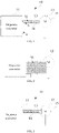
- FIG.1 is a structural view of the microwave oven according to an embodiment of the present disclosure.
- the microwave oven 10 includes a frequency converter 11, a magnetron 12, a first conductor or conductive wire 13, and a second conductor or conductive wire 14.
- a power supply end (not shown) of the frequency converter 11 is connected to a power supply end (not shown) of the magnetron 12 via the first conductor 13, and a ground end (not shown) of the frequency converter 11 is connected to a ground end (not shown) of the magnetron 12 via the second conductor 14.
- the first conductor 13 and a part of the second conductor 14 are arranged in parallel, and a distance between the first conductor 13 and the part of the second conductor 14 is less than a preset distance.
- the frequency converter 11 may be a single-phase, a triple-phase, a high frequency converter, a general frequency converter, or the like.
- the frequency converter 11 at least includes a rectifier (not shown), a filter (not shown), an inverter (not shown).
- the frequency converter 11 is configured to cause a change in power of a power supply for voltage regulation and frequency modification, so that the frequency converter 11 outputs electrical energy of different values to the magnetron 12, and the magnetron 12 is driven to output microwaves of different energy levels.
- the microwave oven 10 may output powers of different sizes according to environmental conditions or users' needs, thus achieving the purpose of energy saving.
- the magnetron 12 is configured for generation and emission of microwave energy during a heating process of the microwave oven 10.
- the magnetron 12 may be a continuous-wave magnetron, pulse-wave magnetron, or the like.
- the magnetron 12 at least includes an antenna (not shown), a cathode (not shown), and an anode (not shown).
- the cathode used as a power supply end is configured to obtain electrical signals from the power supply end of the frequency converter 11 and emit electrons to the anode.
- the electrons are received by the anode to generate an anode current, and the power is further transmitted to the antenna.
- the antenna sends the microwaves to the microwave oven 10, so that food in the microwave oven can be heated.
- the power supply end of the magnetron 12 is the cathode of the magnetron 12, therefore, the first conductor 13 is usually referred to as a cathode wire.
- the first conductor 13 includes two cathode wires (not shown).
- the second conductor 14 is a ground wire, and is configured to connect the ground end of the frequency converter 11 to the ground end of the magnetron 12.
- the anode of the magnetron 12 is connected to the ground end of the magnetron 12.
- a voltage between the two cathode wires of the magnetron 12 is 3.3V, and configured to heat the magnetron 12, so that the electrons can be excited more easily.
- a voltage between the cathode wire and the ground end is 4kV, and configured to convert the electrical energy into the microwave energy.
- a closed loop with current flowing through can emit electromagnetic energy to the surrounding space due to an antenna effect.
- the radiation resistance (R rad ) is equal to 320 ⁇ 4 ⁇ S 2 / ⁇ 4 , where ⁇ is a wavelength corresponding to an electromagnetic frequency, and S is an area of the antenna.
- an electromagnetic frequency band of the RE is about 30MHz to 1GHz.
- the closed loop in the microwave oven 10 basically meets requirements of the circumference of the antenna as described above. Therefore, the larger the area of the closed loop, the stronger the ability to radiate the electromagnetic energy.
- a largest closed loop in the microwave oven 10 is formed by the cathode wire and the ground wire, that is to say, the closed loop 16 formed by the first wire 13 and the second wire 14.
- the area of the largest closed loop 16 in the microwave oven 10 in the embodiment of FIG. 1 is significantly reduced.
- the first conductor 13 used as the cathode wire and the second conductor 14 used as the ground wire are arranged in parallel. In this way, the distance between the cathode wire and the ground wire is reduced, so as to reduce the area of the closed loop 16 formed by the cathode wire and the ground wire, so that the RE of the microwave oven 10 is reduced, thus making the microwave oven 10 meet the EMC standards.
- the second conductor 14 includes a first section a and a second section b, the ground end of the frequency converter 11 is connected to the second section b of the second conductor 14 via the first section a of the second conductor 14, the first section a of the second conductor 14 is routed from the ground end of the frequency converter 11 to the power supply end of the frequency converter 11, and the second section b of the second conductor 14 is arranged in parallel to the first conductor 13.
- a distance between the first conductor 13 and the part of the second conductor 14, that is between the first conductor 13 and the second section b of the second conductor 14, is less than a distance between the power supply end of the frequency converter 11 and a power connection end of the frequency converter 11.
- the first conductor 13 and the second conductor 14 may be bound with each other via a lace (not shown) or a sleeve (not shown). It should be understood that, in other embodiments, the first conductor and the second conductor may be bound with each other via other ways, such as by means of pasting, and the like.
- a sleeve (not shown) may be further sleeved on a periphery of the first conductor 13.
- the ground end of the frequency converter 11 is connected to the ground end of the magnetron 12, and the ground end of the magnetron 12 is grounded.
- a difference between the microwave oven 10 of this embodiment and the microwave oven 10 as shown in FIG. 1 is that the ground end of the magnetron 12 is connected to a housing 15 of the magnetron 12, the ground end of the frequency converter 11 is connected to the housing 15 of the magnetron 12 via the second conductor 14, and the housing 15 of the magnetron 12 is connected to a case (not shown) of the microwave oven 10 so as to be grounded.
- the second conductor 14 may be connected closely to the housing 15 of the magnetron 12, so as to reduce a length of the second conductor 14.
- a difference between the microwave oven 10 of this embodiment and the microwave oven 10 as shown in FIG. 3 is that the housing 15 of the magnetron 12 is arranged with a ground point 16 and the ground end of the frequency converter 11 is connected to the ground point 16 via the second conductor 14.
- the power supply end of the magnetron 12 is arranged on a first side of the magnetron 12, and the ground point 16 is arranged on a second side of the magnetron 12.
- the ground end of the frequency converter 11 is arranged on a first side of the frequency converter 11, and the power supply end of the frequency converter 11 is arranged on a second side of the frequency converter 11.
- a third side of the magnetron 12 is arranged opposite to the second side of the frequency converter 11, the first side of the magnetron 12 and the first side of the frequency converter 11 are arranged on a same side, and the second side of the magnetron 11 is arranged opposite to the third side of the magnetron 12.
- FIG. 5 is a view of the RE test results of the microwave oven in the embodiment of FIG. 4
- FIG. 6 is a view of RE test results of the microwave oven as shown in FIG. 2 .
- the RE of the microwave oven 10 of this embodiment is significantly reduced compared to a technical solution that the ground end of the frequency converter is connected directly to the ground and the ground end of the magnetron is connected directly to the ground.
- each pin of the magnetron and each pin of the frequency converter can also have other setting locations, and the magnetron and the frequency converter can also have other relative position relationships, which will not be repeated here.
- a difference between the microwave oven 10 of this embodiment and the microwave oven 10 as described above is that the ground end of the frequency converter 11 is grounded, the ground end of the magnetron 12 is connected to the housing 15 of the magnetron 12, and the housing 15 of the magnetron 12 is connected to the ground end of the frequency converter 11 via the second conductor 14.
- the second conductor 14 includes a first section c and a second section d
- the housing 15 of the magnetron 12 is connected to the second section d of the second conductor 14 via the first section c of the second conductor 14, the second section d of the second conductor 14 is routed from the power supply end of the frequency converter 11 to the ground end of the frequency converter 11, and the first section c of the second conductor 14 is arranged in parallel to the first conductor 13.
- the microwave oven 10 in this embodiment further includes an Electro Magnetic Interference (EMI) filter board 17. Further, an input end of the EMI filter board 17 is connected to the commercial power 20, an output end of the EMI filter board 17 is connected to an input end of the frequency converter 11, and the EMI filter board 17 is configured to filter the commercial power 20 to filter out high-frequency interference in the commercial power 20, and the like.
- EMI Electro Magnetic Interference
- the EMI filter board 17 is mainly configured to filter the interference of high-frequency pulses of an external power grid to the power supply, and reduce the electromagnetic interference of the power supply to the outside world at the same time.
- the EMI filter board 17 may be implemented as capacitors and inductors.
- the microwave oven includes the frequency converter, the magnetron, the first conductor, and the second conductor.
- the power supply end of the frequency converter is connected to the power supply end of the magnetron via the first conductor
- the ground end of the frequency converter is connected to the ground end of the magnetron via the second conductor.
- the first conductor and the part of the second conductor are arranged in parallel, and the distance between the first conductor and the part of the second conductor is less than the preset distance.
- the first conductor as the cathode wire and the part of the second conductor as the ground wire are arranged in parallel in some embodiments of the present disclosure, so as to reduce a distance between the cathode wire and the ground wire, and then reduce the area of the closed loop formed by the cathode wire and the ground wire, thus reducing the RE of the microwave oven to make the microwave oven meet the EMC standards.
Landscapes
- Physics & Mathematics (AREA)
- Electromagnetism (AREA)
- Engineering & Computer Science (AREA)
- Microelectronics & Electronic Packaging (AREA)
- Chemical & Material Sciences (AREA)
- Combustion & Propulsion (AREA)
- Mechanical Engineering (AREA)
- General Engineering & Computer Science (AREA)
- Control Of High-Frequency Heating Circuits (AREA)
- Electric Ovens (AREA)
Abstract
Description
- The application claims foreign priority to
Chinese Patent Application No. 201910906612.X, filed on September 24, 2019 - The described embodiments relate to the field of electric appliances, and in particular, to a microwave oven.
- Electromagnetic compatibility (EMC) of electric appliances is a very important quality index, which is not only related to operational reliability and use safety of electric appliances, but also affects a normal operation of other equipment and systems. Therefore, microwave ovens must pass the EMC standards before being released into the market.
- During a long period of research and development, inventors of the present disclosure found that the microwave ovens currently on the market are mainly divided into power frequency microwave ovens and variable frequency microwave ovens. The power frequency microwave ovens use commercial frequency transformers to boost voltage, while the variable frequency microwave ovens use frequency conversion technology and convert commercial power into high voltage at high frequencies. The variable frequency microwave ovens use frequency converters to replace the commercial frequency transformers of the power frequency microwave ovens, so that volumes and weights of the microwave ovens have been significantly reduced, and the microwave ovens are widely popular with consumers.
- However, a plurality of electronic components are used in the existing variable frequency microwave ovens due to the arrangement of the frequency converters, resulting in serious EMC problems. For example, severe attenuation vibration is generated at the moment when high current of a switch tube is turned off, and a spike voltage is generated by reverse recovery characteristics of a diode, and both include electromagnetic interference with rich spectrum, which is emitted to a surrounding space through a wiring harness connected to the switch tube or the diode to form Radiated Emission (RE).
- The technical problem to be solved by the present disclosure is how to reduce the RE of the microwave oven to make the microwave oven meet the EMC standards.
- In order to solve the above technical problem, a technical solution of the present disclosure may provide a microwave oven. The microwave oven includes a frequency converter, a magnetron, a first conductor, and a second conductor; a power supply end of the frequency converter is connected to a power supply end of the magnetron via the first conductor, and a ground end of the frequency converter is connected to a ground end of the magnetron via the second conductor; the first conductor and a part of the second conductor are arranged in parallel, and a distance between the first conductor and the part of the second conductor is less than a preset distance.
- In one embodiment, a housing of the magnetron is grounded, the ground end of the magnetron is connected to the housing of the magnetron, and the ground end of the frequency converter is connected to the housing of the magnetron via the second conductor.
- In one embodiment, the second conductor includes a first section, the first section of the second conductor is routed from the ground end of the frequency converter to the power supply end of the frequency converter; and a second section, the ground end of the frequency converter is connected to the second section of the second conductor via the first section of the second conductor, and the second section of the second conductor arranged in parallel to the first conductor.
- In one embodiment, the ground end of the frequency converter is grounded, the ground end of the magnetron is connected to a housing of the magnetron, and the housing of the magnetron is connected to the ground end of the frequency converter via the second conductor.
- In one embodiment, the second conductor includes a first section, the first section of the second conductor is arranged in parallel to the first conductor; and a second section, the second section of the second conductor is routed from the power supply end of the frequency converter to the ground end of the frequency converter, and the housing of the magnetron is connected to the second section of the second conductor via the first section of the second conductor.
- In one embodiment, the housing of the magnetron is arranged with a ground point, and the ground end of the frequency converter is connected to the ground point via the second conductor.
- In one embodiment, the power supply end of the magnetron is arranged on a first side of the magnetron, the ground point is arranged on a second side of the magnetron, the ground end of the frequency converter is arranged on a first side of the frequency converter, and the power supply end of is arranged on a second side of the frequency converter; a third side of the magnetron is arranged opposite to the second side of the frequency converter, the first side of the magnetron and the first side of the frequency converter are arranged on a same side, and the second side of the magnetron is arranged opposite to the third side of the magnetron.
- In one embodiment, a sleeve is sleeved on the first conductor.
- In one embodiment, the first conductor and the second conductor are bound with each other.
- In one embodiment, the distance between the first conductor and the part of the second conductor is less than a distance between the power supply end of the frequency converter and a power connection end of the frequency converter.
- Different from the related art, the present disclosure has the following beneficial effects: the microwave oven according to some embodiments of the present disclosure includes a frequency converter, a magnetron, a first conductor, and a second conductor; a power supply end of the frequency converter is connected to a power supply end of the magnetron via the first conductor, and a ground end of the frequency converter is connected to a ground end of the magnetron via the second conductor. The first conductor and a part of the second conductor are arranged in parallel, and a distance between the first conductor and the part of the second conductor is less than a preset distance. In this way, the first conductor as a cathode wire and the part of the second conductor as a ground wire are arranged in parallel in some embodiments of the present disclosure, so as to reduce a distance between the cathode wire and the ground wire, and then reduce an area of a closed loop formed by the cathode wire and the ground wire, thus reducing the RE of the microwave oven to make the microwave oven meet the EMC standards.
- In order to make the technical solution described in the embodiments of the present disclosure more clearly, the drawings used for the description of the embodiments will be briefly described. Apparently, the drawings described below are only for illustration but not for limitation. It should be understood that, one skilled in the art might acquire other drawings based on these drawings, without paying any creative efforts.
-
FIG. 1 is a structural view of a microwave oven according to an embodiment of the present disclosure. -
FIG. 2 is a structural view of a microwave oven. -
FIG. 3 is a structural view of a microwave oven according to an embodiment of the present disclosure. -
FIG. 4 is a structural view of a microwave oven according to an embodiment of the present disclosure. -
FIG. 5 is a view of RE test results of the microwave oven in the embodiment ofFIG. 4 . -
FIG. 6 is a view of RE test results of the microwave oven as shown inFIG. 2 . -
FIG. 7 is a structural view of a microwave oven according to an embodiment of the present disclosure. -
FIG. 8 is a structural view of a microwave oven according to an embodiment of the present disclosure. - Technical solutions of the embodiments of the present disclosure may be described in detailed by referring to accompanying figures of the embodiments. Obviously, embodiments to be described are only a part of, but not all of, the embodiments of the present disclosure. Any ordinary skilled person in the art may obtain other embodiments without any creative work, and the other embodiments should be included in the scope of the present disclosure.
- In order to suppress the RE of the microwave oven, a magnetic ring is usually applied to the microwave oven by an ordinary skilled person in the art. In this way, the RE is shielded via the magnetic ring, so as to reduce leakage. However, material cost and production cost of the magnetic ring are higher, and a shield effect of the magnetic ring on the RE is not obvious, which cannot suppress full-band electromagnetic wave. Meanwhile, disturbance characteristics of the microwave ovens with different batches are various due to different types, and it is necessary to make different magnetic rings according to the RE test, thus technical versatility is low.
- Therefore, in some embodiments of the present disclosure, a microwave oven is provided, the microwave oven has high versatility and low cost, and the RE of the microwave oven is very small, which can meet the EMC standards. As shown in
FIG. 1, FIG.1 is a structural view of the microwave oven according to an embodiment of the present disclosure. In some embodiments, themicrowave oven 10 includes afrequency converter 11, amagnetron 12, a first conductor orconductive wire 13, and a second conductor orconductive wire 14. A power supply end (not shown) of thefrequency converter 11 is connected to a power supply end (not shown) of themagnetron 12 via thefirst conductor 13, and a ground end (not shown) of thefrequency converter 11 is connected to a ground end (not shown) of themagnetron 12 via thesecond conductor 14. Thefirst conductor 13 and a part of thesecond conductor 14 are arranged in parallel, and a distance between thefirst conductor 13 and the part of thesecond conductor 14 is less than a preset distance. - In some embodiments, the
frequency converter 11 may be a single-phase, a triple-phase, a high frequency converter, a general frequency converter, or the like. Thefrequency converter 11 at least includes a rectifier (not shown), a filter (not shown), an inverter (not shown). Thefrequency converter 11 is configured to cause a change in power of a power supply for voltage regulation and frequency modification, so that the frequency converter 11 outputs electrical energy of different values to themagnetron 12, and themagnetron 12 is driven to output microwaves of different energy levels. In this way, themicrowave oven 10 may output powers of different sizes according to environmental conditions or users' needs, thus achieving the purpose of energy saving. - The
magnetron 12 is configured for generation and emission of microwave energy during a heating process of themicrowave oven 10. In this embodiment, themagnetron 12 may be a continuous-wave magnetron, pulse-wave magnetron, or the like. Themagnetron 12 at least includes an antenna (not shown), a cathode (not shown), and an anode (not shown). Further, the cathode used as a power supply end is configured to obtain electrical signals from the power supply end of thefrequency converter 11 and emit electrons to the anode. The electrons are received by the anode to generate an anode current, and the power is further transmitted to the antenna. In this way, the antenna sends the microwaves to themicrowave oven 10, so that food in the microwave oven can be heated. - The power supply end of the
magnetron 12 is the cathode of themagnetron 12, therefore, thefirst conductor 13 is usually referred to as a cathode wire. In this embodiment, thefirst conductor 13 includes two cathode wires (not shown). Thesecond conductor 14 is a ground wire, and is configured to connect the ground end of thefrequency converter 11 to the ground end of themagnetron 12. The anode of themagnetron 12 is connected to the ground end of themagnetron 12. - In an application scenario, a voltage between the two cathode wires of the
magnetron 12 is 3.3V, and configured to heat themagnetron 12, so that the electrons can be excited more easily. Further, a voltage between the cathode wire and the ground end is 4kV, and configured to convert the electrical energy into the microwave energy. - According to an antenna theory, a closed loop with current flowing through can emit electromagnetic energy to the surrounding space due to an antenna effect. A radiated power can be regarded as a power loss of the current in a resistance, and the resistance is called as a radiation resistance (which represents an ability to radiate the electromagnetic energy), that is to say, P=I2∗Rrad, where P is a total radiation power of the antenna, I is a feed current of the antenna, and Rrad is the radiation resistance. Further, the larger the Rrad, the stronger the antenna radiation capacity. When a circumference (C) of the antenna is less than or equal to 5λ (C ≤ 5λ), the radiation resistance (Rrad) is equal to 320π4∗S2/λ4, where λ is a wavelength corresponding to an electromagnetic frequency, and S is an area of the antenna.
- For the
microwave oven 10, an electromagnetic frequency band of the RE is about 30MHz to 1GHz. The closed loop in themicrowave oven 10 basically meets requirements of the circumference of the antenna as described above. Therefore, the larger the area of the closed loop, the stronger the ability to radiate the electromagnetic energy. A largest closed loop in themicrowave oven 10 is formed by the cathode wire and the ground wire, that is to say, theclosed loop 16 formed by thefirst wire 13 and thesecond wire 14. - During a long period of research and development, inventors of the present disclosure found that there is a long distance between the
frequency converter 11 and themagnetron 12 in a hardware configuration of themicrowave oven 10, so that there is a great distance between the ground end of thefrequency converter 11 and the ground end of themagnetron 12, and there is also a long distance between the power supply end of thefrequency converter 11 and the ground end of thefrequency converter 11. Based on the hardware configuration, if the ground end of thefrequency converter 11 and the ground end of themagnetron 12 are grounded closely or nearby, an area of aclosed loop 20 formed by the cathode wire and the ground wire will be larger, and themicrowave oven 10 has a stronger ability to radiate electromagnetic energy into space, as shown inFIG. 2 . - Compared with the largest
closed loop 20 in the microwave oven as shown inFIG. 2 , the area of the largestclosed loop 16 in themicrowave oven 10 in the embodiment ofFIG. 1 is significantly reduced. - Therefore, in the embodiment, the
first conductor 13 used as the cathode wire and thesecond conductor 14 used as the ground wire are arranged in parallel. In this way, the distance between the cathode wire and the ground wire is reduced, so as to reduce the area of the closedloop 16 formed by the cathode wire and the ground wire, so that the RE of themicrowave oven 10 is reduced, thus making themicrowave oven 10 meet the EMC standards. - Referring to
FIG.1 , in the embodiment, thesecond conductor 14 includes a first section a and a second section b, the ground end of thefrequency converter 11 is connected to the second section b of thesecond conductor 14 via the first section a of thesecond conductor 14, the first section a of thesecond conductor 14 is routed from the ground end of thefrequency converter 11 to the power supply end of thefrequency converter 11, and the second section b of thesecond conductor 14 is arranged in parallel to thefirst conductor 13. - Furthermore, a distance between the
first conductor 13 and the part of thesecond conductor 14, that is between thefirst conductor 13 and the second section b of thesecond conductor 14, is less than a distance between the power supply end of thefrequency converter 11 and a power connection end of thefrequency converter 11. - In this way, it is possible to reduce a distance between a current path, between the power supply end of the
frequency converter 11 in theclosed loop 16 and the power supply end of themagnetron 12, and a current path, between the ground end of thefrequency converter 11 and the ground end of themagnetron 12, thus reducing the area of the closedloop 16. - In some embodiments, in order to reduce the distance between the
first conductor 13 and the second section b of thesecond conductor 14 as much as possible, thefirst conductor 13 and thesecond conductor 14 may be bound with each other via a lace (not shown) or a sleeve (not shown). It should be understood that, in other embodiments, the first conductor and the second conductor may be bound with each other via other ways, such as by means of pasting, and the like. - In some embodiments, in order to prevent an insulation layer outside the
first conductor 13 and/or an insulation layer outside thesecond conductor 14 from being worn or cracked, which may cause a short circuit between thefirst conductor 13 and thesecond conductor 14, a sleeve (not shown) may be further sleeved on a periphery of thefirst conductor 13. - In this embodiment, the ground end of the
frequency converter 11 is connected to the ground end of themagnetron 12, and the ground end of themagnetron 12 is grounded. - In another embodiment, as shown in
FIG. 3 , a difference between themicrowave oven 10 of this embodiment and themicrowave oven 10 as shown inFIG. 1 is that the ground end of themagnetron 12 is connected to ahousing 15 of themagnetron 12, the ground end of thefrequency converter 11 is connected to thehousing 15 of themagnetron 12 via thesecond conductor 14, and thehousing 15 of themagnetron 12 is connected to a case (not shown) of themicrowave oven 10 so as to be grounded. - In this way, the
second conductor 14 may be connected closely to thehousing 15 of themagnetron 12, so as to reduce a length of thesecond conductor 14. - In another embodiment, as shown in
FIG. 4 , a difference between themicrowave oven 10 of this embodiment and themicrowave oven 10 as shown inFIG. 3 is that thehousing 15 of themagnetron 12 is arranged with aground point 16 and the ground end of thefrequency converter 11 is connected to theground point 16 via thesecond conductor 14. - In some embodiments, the power supply end of the
magnetron 12 is arranged on a first side of themagnetron 12, and theground point 16 is arranged on a second side of themagnetron 12. The ground end of thefrequency converter 11 is arranged on a first side of thefrequency converter 11, and the power supply end of thefrequency converter 11 is arranged on a second side of thefrequency converter 11. Furthermore, a third side of themagnetron 12 is arranged opposite to the second side of thefrequency converter 11, the first side of themagnetron 12 and the first side of thefrequency converter 11 are arranged on a same side, and the second side of themagnetron 11 is arranged opposite to the third side of themagnetron 12. - As shown in
FIG. 5 and6 ,FIG. 5 is a view of the RE test results of the microwave oven in the embodiment ofFIG. 4 , andFIG. 6 is a view of RE test results of the microwave oven as shown inFIG. 2 . Obviously, it should be found that the RE of themicrowave oven 10 of this embodiment is significantly reduced compared to a technical solution that the ground end of the frequency converter is connected directly to the ground and the ground end of the magnetron is connected directly to the ground. - In some embodiments, it should be understood that each pin of the magnetron and each pin of the frequency converter can also have other setting locations, and the magnetron and the frequency converter can also have other relative position relationships, which will not be repeated here.
- In another embodiment, as shown in
FIG. 7 , a difference between themicrowave oven 10 of this embodiment and themicrowave oven 10 as described above is that the ground end of thefrequency converter 11 is grounded, the ground end of themagnetron 12 is connected to thehousing 15 of themagnetron 12, and thehousing 15 of themagnetron 12 is connected to the ground end of thefrequency converter 11 via thesecond conductor 14. - In some embodiments, the
second conductor 14 includes a first section c and a second section d, and thehousing 15 of themagnetron 12 is connected to the second section d of thesecond conductor 14 via the first section c of thesecond conductor 14, the second section d of thesecond conductor 14 is routed from the power supply end of thefrequency converter 11 to the ground end of thefrequency converter 11, and the first section c of thesecond conductor 14 is arranged in parallel to thefirst conductor 13. - In another embodiment, as shown in
FIG. 8 , based on themicrowave oven 10 in the embodiment ofFIG. 1 , themicrowave oven 10 in this embodiment further includes an Electro Magnetic Interference (EMI)filter board 17. Further, an input end of theEMI filter board 17 is connected to thecommercial power 20, an output end of theEMI filter board 17 is connected to an input end of thefrequency converter 11, and theEMI filter board 17 is configured to filter thecommercial power 20 to filter out high-frequency interference in thecommercial power 20, and the like. - After the
commercial power 20 is supplied to the power supply, thecommercial power 20 firstly passes through theEMI filter board 17. TheEMI filter board 17 is mainly configured to filter the interference of high-frequency pulses of an external power grid to the power supply, and reduce the electromagnetic interference of the power supply to the outside world at the same time. - The
EMI filter board 17 may be implemented as capacitors and inductors. - Different from the related art, the microwave oven according to some embodiments of the present disclosure includes the frequency converter, the magnetron, the first conductor, and the second conductor. The power supply end of the frequency converter is connected to the power supply end of the magnetron via the first conductor, and the ground end of the frequency converter is connected to the ground end of the magnetron via the second conductor. The first conductor and the part of the second conductor are arranged in parallel, and the distance between the first conductor and the part of the second conductor is less than the preset distance. In this way, the first conductor as the cathode wire and the part of the second conductor as the ground wire are arranged in parallel in some embodiments of the present disclosure, so as to reduce a distance between the cathode wire and the ground wire, and then reduce the area of the closed loop formed by the cathode wire and the ground wire, thus reducing the RE of the microwave oven to make the microwave oven meet the EMC standards.
- The above are only embodiments of the present disclosure and are not intended to limit the scope of the present disclosure. Any equivalent structural changes made under the concept of the present disclosure, using the contents of the specification of the present disclosure and the accompanying drawings, or applied directly/indirectly in other related fields of technology are included in the scope of protection of the present disclosure.
Claims (10)
- A microwave oven, comprising:a frequency converter;a magnetron;a first conductor, wherein a power supply end of the frequency converter is connected to a power supply end of the magnetron via the first conductor; anda second conductor, wherein a ground end of the frequency converter is connected to a ground end of the magnetron via the second conductor;wherein the first conductor and a part of the second conductor are arranged in parallel, and a distance between the first conductor and the part of the second conductor is less than a preset distance.
- The microwave oven as claimed in claim 1, wherein a housing of the magnetron is grounded, the ground end of the magnetron is connected to the housing of the magnetron, and the ground end of the frequency converter is connected to the housing of the magnetron via the second conductor.
- The microwave oven as claimed in claim 2, wherein the second conductor comprises:a first section, wherein the first section of the second conductor is routed from the ground end of the frequency converter to the power supply end of the frequency converter; anda second section, wherein the ground end of the frequency converter is connected to the second section of the second conductor via the first section of the second conductor, and the second section of the second conductor arranged in parallel to the first conductor.
- The microwave oven as claimed in claim 1, wherein the ground end of the frequency converter is grounded, the ground end of the magnetron is connected to a housing of the magnetron, and the housing of the magnetron is connected to the ground end of the frequency converter via the second conductor.
- The microwave oven as claimed in claim 4, wherein the second conductor comprises:a first section, wherein the first section of the second conductor is arranged in parallel to the first conductor; anda second section, wherein the second section of the second conductor is routed from the power supply end of the frequency converter to the ground end of the frequency converter, and the housing of the magnetron is connected to the second section of the second conductor via the first section of the second conductor.
- The microwave oven as claimed in claim 2, wherein the housing of the magnetron is arranged with a ground point, and the ground end of the frequency converter is connected to the ground point via the second conductor.
- The microwave oven as claimed in claim 6, wherein the power supply end of the magnetron is arranged on a first side of the magnetron, the ground point is arranged on a second side of the magnetron, the ground end of the frequency converter is arranged on a first side of the frequency converter, and the power supply end of is arranged on a second side of the frequency converter;
wherein a third side of the magnetron is arranged opposite to the second side of the frequency converter, the first side of the magnetron and the first side of the frequency converter are arranged on a same side, and the second side of the magnetron is arranged opposite to the third side of the magnetron. - The microwave oven as claimed in claim 1, wherein a sleeve is sleeved on the first conductor.
- The microwave oven as claimed in claim 1, wherein the first conductor and the second conductor are bound with each other.
- The microwave oven as claimed in claim 1, wherein the distance between the first conductor and the part of the second conductor is less than a distance between the power supply end of the frequency converter and a power connection end of the frequency converter.
Applications Claiming Priority (2)
| Application Number | Priority Date | Filing Date | Title |
|---|---|---|---|
| CN201910906612.XA CN110831272B (en) | 2019-09-24 | 2019-09-24 | a microwave oven |
| PCT/CN2019/124120 WO2021056834A1 (en) | 2019-09-24 | 2019-12-09 | Microwave oven |
Publications (3)
| Publication Number | Publication Date |
|---|---|
| EP3998840A1 true EP3998840A1 (en) | 2022-05-18 |
| EP3998840A4 EP3998840A4 (en) | 2022-10-12 |
| EP3998840B1 EP3998840B1 (en) | 2023-06-21 |
Family
ID=69548187
Family Applications (1)
| Application Number | Title | Priority Date | Filing Date |
|---|---|---|---|
| EP19946955.2A Active EP3998840B1 (en) | 2019-09-24 | 2019-12-09 | Microwave oven |
Country Status (5)
| Country | Link |
|---|---|
| US (1) | US20220183120A1 (en) |
| EP (1) | EP3998840B1 (en) |
| JP (1) | JP7327888B2 (en) |
| CN (1) | CN110831272B (en) |
| WO (1) | WO2021056834A1 (en) |
Family Cites Families (16)
| Publication number | Priority date | Publication date | Assignee | Title |
|---|---|---|---|---|
| JPS5342254U (en) * | 1976-09-16 | 1978-04-12 | ||
| US4356431A (en) * | 1978-02-21 | 1982-10-26 | Advance Transformer Company | Magnetron energizing circuit |
| JPH0685350B2 (en) * | 1985-11-15 | 1994-10-26 | 松下電器産業株式会社 | High frequency heating device |
| JPS63150881A (en) * | 1986-12-15 | 1988-06-23 | 松下電器産業株式会社 | Radio frequency heater |
| US4977301A (en) * | 1988-10-13 | 1990-12-11 | Matsushita Electric Industrial Co., Ltd. | High-frequency heating apparatus using frequency-converter-type power supply |
| JP3168929B2 (en) * | 1996-12-11 | 2001-05-21 | 松下電器産業株式会社 | High frequency heating equipment |
| JP2000195657A (en) | 1998-12-25 | 2000-07-14 | Matsushita Electronics Industry Corp | Microwave-oven power supply part and microwave oven |
| JP2004241311A (en) | 2003-02-07 | 2004-08-26 | Matsushita Electric Ind Co Ltd | High frequency heating equipment |
| JP2005044765A (en) | 2003-07-21 | 2005-02-17 | Susumu Kiyokawa | Electric wire, power-transmission method and electrical equipment |
| CN200972169Y (en) * | 2006-09-18 | 2007-11-07 | 上海松下微波炉有限公司 | Microwave oven |
| KR101039476B1 (en) * | 2008-07-28 | 2011-06-07 | 엘지전자 주식회사 | Doors and microwave ovens containing them |
| CN201294142Y (en) | 2008-09-20 | 2009-08-19 | 梁伟国 | Microwave oven |
| JP2011159615A (en) | 2010-02-04 | 2011-08-18 | Panasonic Corp | High frequency heating device |
| CN105253781A (en) * | 2015-10-31 | 2016-01-20 | 长治清华机械厂 | Moment limiter suitable for complex electromagnetic compatibility environment |
| CN206302344U (en) * | 2016-12-29 | 2017-07-04 | 广东美的厨房电器制造有限公司 | Frequency converter and micro-wave oven |
| CN107191980A (en) * | 2017-06-20 | 2017-09-22 | 广东美的厨房电器制造有限公司 | The determination methods and frequency-conversion microwave oven of frequency-conversion microwave oven state of ground wire |
-
2019
- 2019-09-24 CN CN201910906612.XA patent/CN110831272B/en active Active
- 2019-12-09 WO PCT/CN2019/124120 patent/WO2021056834A1/en not_active Ceased
- 2019-12-09 EP EP19946955.2A patent/EP3998840B1/en active Active
- 2019-12-09 JP JP2022509668A patent/JP7327888B2/en active Active
-
2022
- 2022-02-23 US US17/679,022 patent/US20220183120A1/en active Pending
Also Published As
| Publication number | Publication date |
|---|---|
| CN110831272B (en) | 2021-01-26 |
| WO2021056834A1 (en) | 2021-04-01 |
| CN110831272A (en) | 2020-02-21 |
| EP3998840B1 (en) | 2023-06-21 |
| JP2022545396A (en) | 2022-10-27 |
| JP7327888B2 (en) | 2023-08-16 |
| US20220183120A1 (en) | 2022-06-09 |
| EP3998840A4 (en) | 2022-10-12 |
Similar Documents
| Publication | Publication Date | Title |
|---|---|---|
| US8885369B2 (en) | Power regeneration device, method of regenerating power, power storage system, method of storing power, and high frequency device | |
| US20210151250A1 (en) | Coil Module, Wireless Charging Transmitting Apparatus, Wireless Charging Receiving Apparatus, Wireless Charging System, and Mobile Terminal | |
| CA2153834C (en) | Power distribution system having effectively zero electromagnetic field radiation | |
| US6188297B1 (en) | Low-EMI circuit board and low-EMI cable connector | |
| US4984146A (en) | Suppression of radiated EMI for power supplies | |
| EP2887378B1 (en) | Magnetron and high-frequency heating apparatus having the same | |
| US11750035B2 (en) | Wireless power transfer device with electromagnetic interference (EMI) suppression | |
| US3681652A (en) | Capacitive filter for suppression of spurious electrical radiation | |
| EP3998840B1 (en) | Microwave oven | |
| JP2014161154A (en) | Noise countermeasure filter | |
| KR101675401B1 (en) | Reactor for Electromagnetic Interference Filter And Electromagnetic Interference Filter Using Same | |
| EP3148050A1 (en) | Protecting wireless communication components in a highly resonant field | |
| Wong et al. | Electromagnetic interference of switching mode power regulator with chaotic frequency modulation | |
| CN208063043U (en) | A kind of anti-interference switch power transformer | |
| US3531613A (en) | Capacitive filter for suppression of spurious electrical radiation | |
| CN115313847A (en) | High-voltage power supply of electromagnetic compatible millimeter wave transmitter and generation method thereof | |
| Mu et al. | The design, experiment investigation, and experience of 324 MHz/3 MW klystron power source system for CSNS Linac | |
| US20220302769A1 (en) | Wireless power transmission system and wireless power reception device | |
| AU2012215196B2 (en) | Filter for a magnetron power supply lead | |
| US20120012761A1 (en) | High-power pulse-signal radiation system | |
| CN203761261U (en) | Anti-radiation switching mode power supply | |
| Waghela et al. | Switched-mode power supply design guidelines for smartphones and tablets for reducing rf emissions | |
| CN109698731B (en) | Terahertz electromagnetic interference system and application method thereof | |
| JP2019532241A (en) | Microwave oven having power supply unit for generator with discharge function | |
| Jeong et al. | Design of 36 W Class LED Lighting Equipment Radiation Disturbance Reduction |
Legal Events
| Date | Code | Title | Description |
|---|---|---|---|
| STAA | Information on the status of an ep patent application or granted ep patent |
Free format text: STATUS: THE INTERNATIONAL PUBLICATION HAS BEEN MADE |
|
| PUAI | Public reference made under article 153(3) epc to a published international application that has entered the european phase |
Free format text: ORIGINAL CODE: 0009012 |
|
| STAA | Information on the status of an ep patent application or granted ep patent |
Free format text: STATUS: REQUEST FOR EXAMINATION WAS MADE |
|
| 17P | Request for examination filed |
Effective date: 20220214 |
|
| AK | Designated contracting states |
Kind code of ref document: A1 Designated state(s): AL AT BE BG CH CY CZ DE DK EE ES FI FR GB GR HR HU IE IS IT LI LT LU LV MC MK MT NL NO PL PT RO RS SE SI SK SM TR |
|
| REG | Reference to a national code |
Ref legal event code: R079 Ipc: H05B0006660000 Ref country code: DE Ref legal event code: R079 Ref document number: 602019031536 Country of ref document: DE Free format text: PREVIOUS MAIN CLASS: H05B0006640000 Ipc: H05B0006660000 |
|
| A4 | Supplementary search report drawn up and despatched |
Effective date: 20220914 |
|
| RIC1 | Information provided on ipc code assigned before grant |
Ipc: H05B 6/66 20060101AFI20220908BHEP |
|
| DAV | Request for validation of the european patent (deleted) | ||
| DAX | Request for extension of the european patent (deleted) | ||
| GRAP | Despatch of communication of intention to grant a patent |
Free format text: ORIGINAL CODE: EPIDOSNIGR1 |
|
| STAA | Information on the status of an ep patent application or granted ep patent |
Free format text: STATUS: GRANT OF PATENT IS INTENDED |
|
| INTG | Intention to grant announced |
Effective date: 20230322 |
|
| GRAS | Grant fee paid |
Free format text: ORIGINAL CODE: EPIDOSNIGR3 |
|
| GRAA | (expected) grant |
Free format text: ORIGINAL CODE: 0009210 |
|
| STAA | Information on the status of an ep patent application or granted ep patent |
Free format text: STATUS: THE PATENT HAS BEEN GRANTED |
|
| AK | Designated contracting states |
Kind code of ref document: B1 Designated state(s): AL AT BE BG CH CY CZ DE DK EE ES FI FR GB GR HR HU IE IS IT LI LT LU LV MC MK MT NL NO PL PT RO RS SE SI SK SM TR |
|
| REG | Reference to a national code |
Ref country code: CH Ref legal event code: EP |
|
| REG | Reference to a national code |
Ref country code: DE Ref legal event code: R096 Ref document number: 602019031536 Country of ref document: DE |
|
| REG | Reference to a national code |
Ref country code: AT Ref legal event code: REF Ref document number: 1581847 Country of ref document: AT Kind code of ref document: T Effective date: 20230715 |
|
| REG | Reference to a national code |
Ref country code: IE Ref legal event code: FG4D |
|
| REG | Reference to a national code |
Ref country code: LT Ref legal event code: MG9D |
|
| REG | Reference to a national code |
Ref country code: NL Ref legal event code: MP Effective date: 20230621 |
|
| PG25 | Lapsed in a contracting state [announced via postgrant information from national office to epo] |
Ref country code: SE Free format text: LAPSE BECAUSE OF FAILURE TO SUBMIT A TRANSLATION OF THE DESCRIPTION OR TO PAY THE FEE WITHIN THE PRESCRIBED TIME-LIMIT Effective date: 20230621 Ref country code: NO Free format text: LAPSE BECAUSE OF FAILURE TO SUBMIT A TRANSLATION OF THE DESCRIPTION OR TO PAY THE FEE WITHIN THE PRESCRIBED TIME-LIMIT Effective date: 20230921 |
|
| REG | Reference to a national code |
Ref country code: AT Ref legal event code: MK05 Ref document number: 1581847 Country of ref document: AT Kind code of ref document: T Effective date: 20230621 |
|
| PG25 | Lapsed in a contracting state [announced via postgrant information from national office to epo] |
Ref country code: RS Free format text: LAPSE BECAUSE OF FAILURE TO SUBMIT A TRANSLATION OF THE DESCRIPTION OR TO PAY THE FEE WITHIN THE PRESCRIBED TIME-LIMIT Effective date: 20230621 Ref country code: NL Free format text: LAPSE BECAUSE OF FAILURE TO SUBMIT A TRANSLATION OF THE DESCRIPTION OR TO PAY THE FEE WITHIN THE PRESCRIBED TIME-LIMIT Effective date: 20230621 Ref country code: LV Free format text: LAPSE BECAUSE OF FAILURE TO SUBMIT A TRANSLATION OF THE DESCRIPTION OR TO PAY THE FEE WITHIN THE PRESCRIBED TIME-LIMIT Effective date: 20230621 Ref country code: LT Free format text: LAPSE BECAUSE OF FAILURE TO SUBMIT A TRANSLATION OF THE DESCRIPTION OR TO PAY THE FEE WITHIN THE PRESCRIBED TIME-LIMIT Effective date: 20230621 Ref country code: HR Free format text: LAPSE BECAUSE OF FAILURE TO SUBMIT A TRANSLATION OF THE DESCRIPTION OR TO PAY THE FEE WITHIN THE PRESCRIBED TIME-LIMIT Effective date: 20230621 Ref country code: GR Free format text: LAPSE BECAUSE OF FAILURE TO SUBMIT A TRANSLATION OF THE DESCRIPTION OR TO PAY THE FEE WITHIN THE PRESCRIBED TIME-LIMIT Effective date: 20230922 |
|
| PG25 | Lapsed in a contracting state [announced via postgrant information from national office to epo] |
Ref country code: FI Free format text: LAPSE BECAUSE OF FAILURE TO SUBMIT A TRANSLATION OF THE DESCRIPTION OR TO PAY THE FEE WITHIN THE PRESCRIBED TIME-LIMIT Effective date: 20230621 |
|
| PG25 | Lapsed in a contracting state [announced via postgrant information from national office to epo] |
Ref country code: SK Free format text: LAPSE BECAUSE OF FAILURE TO SUBMIT A TRANSLATION OF THE DESCRIPTION OR TO PAY THE FEE WITHIN THE PRESCRIBED TIME-LIMIT Effective date: 20230621 |
|
| PG25 | Lapsed in a contracting state [announced via postgrant information from national office to epo] |
Ref country code: ES Free format text: LAPSE BECAUSE OF FAILURE TO SUBMIT A TRANSLATION OF THE DESCRIPTION OR TO PAY THE FEE WITHIN THE PRESCRIBED TIME-LIMIT Effective date: 20230621 |
|
| PG25 | Lapsed in a contracting state [announced via postgrant information from national office to epo] |
Ref country code: IS Free format text: LAPSE BECAUSE OF FAILURE TO SUBMIT A TRANSLATION OF THE DESCRIPTION OR TO PAY THE FEE WITHIN THE PRESCRIBED TIME-LIMIT Effective date: 20231021 |
|
| PG25 | Lapsed in a contracting state [announced via postgrant information from national office to epo] |
Ref country code: SM Free format text: LAPSE BECAUSE OF FAILURE TO SUBMIT A TRANSLATION OF THE DESCRIPTION OR TO PAY THE FEE WITHIN THE PRESCRIBED TIME-LIMIT Effective date: 20230621 Ref country code: SK Free format text: LAPSE BECAUSE OF FAILURE TO SUBMIT A TRANSLATION OF THE DESCRIPTION OR TO PAY THE FEE WITHIN THE PRESCRIBED TIME-LIMIT Effective date: 20230621 Ref country code: RO Free format text: LAPSE BECAUSE OF FAILURE TO SUBMIT A TRANSLATION OF THE DESCRIPTION OR TO PAY THE FEE WITHIN THE PRESCRIBED TIME-LIMIT Effective date: 20230621 Ref country code: PT Free format text: LAPSE BECAUSE OF FAILURE TO SUBMIT A TRANSLATION OF THE DESCRIPTION OR TO PAY THE FEE WITHIN THE PRESCRIBED TIME-LIMIT Effective date: 20231023 Ref country code: IS Free format text: LAPSE BECAUSE OF FAILURE TO SUBMIT A TRANSLATION OF THE DESCRIPTION OR TO PAY THE FEE WITHIN THE PRESCRIBED TIME-LIMIT Effective date: 20231021 Ref country code: ES Free format text: LAPSE BECAUSE OF FAILURE TO SUBMIT A TRANSLATION OF THE DESCRIPTION OR TO PAY THE FEE WITHIN THE PRESCRIBED TIME-LIMIT Effective date: 20230621 Ref country code: EE Free format text: LAPSE BECAUSE OF FAILURE TO SUBMIT A TRANSLATION OF THE DESCRIPTION OR TO PAY THE FEE WITHIN THE PRESCRIBED TIME-LIMIT Effective date: 20230621 Ref country code: CZ Free format text: LAPSE BECAUSE OF FAILURE TO SUBMIT A TRANSLATION OF THE DESCRIPTION OR TO PAY THE FEE WITHIN THE PRESCRIBED TIME-LIMIT Effective date: 20230621 Ref country code: AT Free format text: LAPSE BECAUSE OF FAILURE TO SUBMIT A TRANSLATION OF THE DESCRIPTION OR TO PAY THE FEE WITHIN THE PRESCRIBED TIME-LIMIT Effective date: 20230621 |
|
| PG25 | Lapsed in a contracting state [announced via postgrant information from national office to epo] |
Ref country code: PL Free format text: LAPSE BECAUSE OF FAILURE TO SUBMIT A TRANSLATION OF THE DESCRIPTION OR TO PAY THE FEE WITHIN THE PRESCRIBED TIME-LIMIT Effective date: 20230621 |
|
| REG | Reference to a national code |
Ref country code: DE Ref legal event code: R097 Ref document number: 602019031536 Country of ref document: DE |
|
| PLBE | No opposition filed within time limit |
Free format text: ORIGINAL CODE: 0009261 |
|
| STAA | Information on the status of an ep patent application or granted ep patent |
Free format text: STATUS: NO OPPOSITION FILED WITHIN TIME LIMIT |
|
| PG25 | Lapsed in a contracting state [announced via postgrant information from national office to epo] |
Ref country code: DK Free format text: LAPSE BECAUSE OF FAILURE TO SUBMIT A TRANSLATION OF THE DESCRIPTION OR TO PAY THE FEE WITHIN THE PRESCRIBED TIME-LIMIT Effective date: 20230621 |
|
| PG25 | Lapsed in a contracting state [announced via postgrant information from national office to epo] |
Ref country code: SI Free format text: LAPSE BECAUSE OF FAILURE TO SUBMIT A TRANSLATION OF THE DESCRIPTION OR TO PAY THE FEE WITHIN THE PRESCRIBED TIME-LIMIT Effective date: 20230621 |
|
| 26N | No opposition filed |
Effective date: 20240322 |
|
| PG25 | Lapsed in a contracting state [announced via postgrant information from national office to epo] |
Ref country code: SI Free format text: LAPSE BECAUSE OF FAILURE TO SUBMIT A TRANSLATION OF THE DESCRIPTION OR TO PAY THE FEE WITHIN THE PRESCRIBED TIME-LIMIT Effective date: 20230621 Ref country code: IT Free format text: LAPSE BECAUSE OF FAILURE TO SUBMIT A TRANSLATION OF THE DESCRIPTION OR TO PAY THE FEE WITHIN THE PRESCRIBED TIME-LIMIT Effective date: 20230621 |
|
| P01 | Opt-out of the competence of the unified patent court (upc) registered |
Effective date: 20240520 |
|
| REG | Reference to a national code |
Ref country code: CH Ref legal event code: PL |
|
| PG25 | Lapsed in a contracting state [announced via postgrant information from national office to epo] |
Ref country code: LU Free format text: LAPSE BECAUSE OF NON-PAYMENT OF DUE FEES Effective date: 20231209 |
|
| PG25 | Lapsed in a contracting state [announced via postgrant information from national office to epo] |
Ref country code: MC Free format text: LAPSE BECAUSE OF FAILURE TO SUBMIT A TRANSLATION OF THE DESCRIPTION OR TO PAY THE FEE WITHIN THE PRESCRIBED TIME-LIMIT Effective date: 20230621 |
|
| REG | Reference to a national code |
Ref country code: BE Ref legal event code: MM Effective date: 20231231 |
|
| PG25 | Lapsed in a contracting state [announced via postgrant information from national office to epo] |
Ref country code: MC Free format text: LAPSE BECAUSE OF FAILURE TO SUBMIT A TRANSLATION OF THE DESCRIPTION OR TO PAY THE FEE WITHIN THE PRESCRIBED TIME-LIMIT Effective date: 20230621 Ref country code: LU Free format text: LAPSE BECAUSE OF NON-PAYMENT OF DUE FEES Effective date: 20231209 |
|
| REG | Reference to a national code |
Ref country code: IE Ref legal event code: MM4A |
|
| PG25 | Lapsed in a contracting state [announced via postgrant information from national office to epo] |
Ref country code: IE Free format text: LAPSE BECAUSE OF NON-PAYMENT OF DUE FEES Effective date: 20231209 |
|
| PG25 | Lapsed in a contracting state [announced via postgrant information from national office to epo] |
Ref country code: BE Free format text: LAPSE BECAUSE OF NON-PAYMENT OF DUE FEES Effective date: 20231231 |
|
| PG25 | Lapsed in a contracting state [announced via postgrant information from national office to epo] |
Ref country code: CH Free format text: LAPSE BECAUSE OF NON-PAYMENT OF DUE FEES Effective date: 20231231 |
|
| PG25 | Lapsed in a contracting state [announced via postgrant information from national office to epo] |
Ref country code: IE Free format text: LAPSE BECAUSE OF NON-PAYMENT OF DUE FEES Effective date: 20231209 Ref country code: CH Free format text: LAPSE BECAUSE OF NON-PAYMENT OF DUE FEES Effective date: 20231231 Ref country code: BE Free format text: LAPSE BECAUSE OF NON-PAYMENT OF DUE FEES Effective date: 20231231 |
|
| PG25 | Lapsed in a contracting state [announced via postgrant information from national office to epo] |
Ref country code: BG Free format text: LAPSE BECAUSE OF FAILURE TO SUBMIT A TRANSLATION OF THE DESCRIPTION OR TO PAY THE FEE WITHIN THE PRESCRIBED TIME-LIMIT Effective date: 20230621 |
|
| PG25 | Lapsed in a contracting state [announced via postgrant information from national office to epo] |
Ref country code: BG Free format text: LAPSE BECAUSE OF FAILURE TO SUBMIT A TRANSLATION OF THE DESCRIPTION OR TO PAY THE FEE WITHIN THE PRESCRIBED TIME-LIMIT Effective date: 20230621 |
|
| PG25 | Lapsed in a contracting state [announced via postgrant information from national office to epo] |
Ref country code: CY Free format text: LAPSE BECAUSE OF FAILURE TO SUBMIT A TRANSLATION OF THE DESCRIPTION OR TO PAY THE FEE WITHIN THE PRESCRIBED TIME-LIMIT; INVALID AB INITIO Effective date: 20191209 |
|
| PG25 | Lapsed in a contracting state [announced via postgrant information from national office to epo] |
Ref country code: HU Free format text: LAPSE BECAUSE OF FAILURE TO SUBMIT A TRANSLATION OF THE DESCRIPTION OR TO PAY THE FEE WITHIN THE PRESCRIBED TIME-LIMIT; INVALID AB INITIO Effective date: 20191209 |
|
| PG25 | Lapsed in a contracting state [announced via postgrant information from national office to epo] |
Ref country code: TR Free format text: LAPSE BECAUSE OF FAILURE TO SUBMIT A TRANSLATION OF THE DESCRIPTION OR TO PAY THE FEE WITHIN THE PRESCRIBED TIME-LIMIT Effective date: 20230621 |
|
| PGFP | Annual fee paid to national office [announced via postgrant information from national office to epo] |
Ref country code: DE Payment date: 20251212 Year of fee payment: 7 |
|
| PGFP | Annual fee paid to national office [announced via postgrant information from national office to epo] |
Ref country code: GB Payment date: 20251211 Year of fee payment: 7 |
|
| PGFP | Annual fee paid to national office [announced via postgrant information from national office to epo] |
Ref country code: FR Payment date: 20251212 Year of fee payment: 7 |