EP3998692A1 - Output control device and method, and storage medium - Google Patents
Output control device and method, and storage medium Download PDFInfo
- Publication number
- EP3998692A1 EP3998692A1 EP19942614.9A EP19942614A EP3998692A1 EP 3998692 A1 EP3998692 A1 EP 3998692A1 EP 19942614 A EP19942614 A EP 19942614A EP 3998692 A1 EP3998692 A1 EP 3998692A1
- Authority
- EP
- European Patent Office
- Prior art keywords
- circuit
- sub
- switch
- output
- turned
- Prior art date
- Legal status (The legal status is an assumption and is not a legal conclusion. Google has not performed a legal analysis and makes no representation as to the accuracy of the status listed.)
- Pending
Links
Images


Classifications
-
- H—ELECTRICITY
- H02—GENERATION; CONVERSION OR DISTRIBUTION OF ELECTRIC POWER
- H02J—ELECTRIC POWER NETWORKS; CIRCUIT ARRANGEMENTS OR SYSTEMS FOR SUPPLYING OR DISTRIBUTING ELECTRIC POWER; SYSTEMS FOR STORING ELECTRIC ENERGY
- H02J50/00—Circuit arrangements or systems for wireless supply or distribution of electric power
- H02J50/10—Circuit arrangements or systems for wireless supply or distribution of electric power using inductive coupling
-
- H—ELECTRICITY
- H02—GENERATION; CONVERSION OR DISTRIBUTION OF ELECTRIC POWER
- H02J—ELECTRIC POWER NETWORKS; CIRCUIT ARRANGEMENTS OR SYSTEMS FOR SUPPLYING OR DISTRIBUTING ELECTRIC POWER; SYSTEMS FOR STORING ELECTRIC ENERGY
- H02J50/00—Circuit arrangements or systems for wireless supply or distribution of electric power
- H02J50/10—Circuit arrangements or systems for wireless supply or distribution of electric power using inductive coupling
- H02J50/12—Circuit arrangements or systems for wireless supply or distribution of electric power using inductive coupling of the resonant type
-
- B—PERFORMING OPERATIONS; TRANSPORTING
- B60—VEHICLES IN GENERAL
- B60L—PROPULSION OF ELECTRICALLY-PROPELLED VEHICLES; SUPPLYING ELECTRIC POWER FOR AUXILIARY EQUIPMENT OF ELECTRICALLY-PROPELLED VEHICLES; ELECTRODYNAMIC BRAKE SYSTEMS FOR VEHICLES IN GENERAL; MAGNETIC SUSPENSION OR LEVITATION FOR VEHICLES; MONITORING OPERATING VARIABLES OF ELECTRICALLY-PROPELLED VEHICLES; ELECTRIC SAFETY DEVICES FOR ELECTRICALLY-PROPELLED VEHICLES
- B60L53/00—Methods of charging batteries, specially adapted for electric vehicles; Charging stations or on-board charging equipment therefor; Exchange of energy storage elements in electric vehicles
- B60L53/10—Methods of charging batteries, specially adapted for electric vehicles; Charging stations or on-board charging equipment therefor; Exchange of energy storage elements in electric vehicles characterised by the energy transfer between the charging station and the vehicle
- B60L53/12—Inductive energy transfer
-
- H—ELECTRICITY
- H02—GENERATION; CONVERSION OR DISTRIBUTION OF ELECTRIC POWER
- H02J—ELECTRIC POWER NETWORKS; CIRCUIT ARRANGEMENTS OR SYSTEMS FOR SUPPLYING OR DISTRIBUTING ELECTRIC POWER; SYSTEMS FOR STORING ELECTRIC ENERGY
- H02J7/00—Circuit arrangements for charging or discharging batteries or for supplying loads from batteries
- H02J7/70—Circuit arrangements for charging or discharging batteries or for supplying loads from batteries characterised by the mechanical construction
- H02J7/731—Circuit arrangements for charging or discharging batteries or for supplying loads from batteries characterised by the mechanical construction specially adapted for holding portable devices containing batteries
-
- H—ELECTRICITY
- H04—ELECTRIC COMMUNICATION TECHNIQUE
- H04B—TRANSMISSION
- H04B5/00—Near-field transmission systems, e.g. inductive or capacitive transmission systems
- H04B5/20—Near-field transmission systems, e.g. inductive or capacitive transmission systems characterised by the transmission technique; characterised by the transmission medium
- H04B5/24—Inductive coupling
- H04B5/26—Inductive coupling using coils
-
- H—ELECTRICITY
- H04—ELECTRIC COMMUNICATION TECHNIQUE
- H04B—TRANSMISSION
- H04B5/00—Near-field transmission systems, e.g. inductive or capacitive transmission systems
- H04B5/70—Near-field transmission systems, e.g. inductive or capacitive transmission systems specially adapted for specific purposes
- H04B5/79—Near-field transmission systems, e.g. inductive or capacitive transmission systems specially adapted for specific purposes for data transfer in combination with power transfer
-
- H—ELECTRICITY
- H05—ELECTRIC TECHNIQUES NOT OTHERWISE PROVIDED FOR
- H05B—ELECTRIC HEATING; ELECTRIC LIGHT SOURCES NOT OTHERWISE PROVIDED FOR; CIRCUIT ARRANGEMENTS FOR ELECTRIC LIGHT SOURCES, IN GENERAL
- H05B1/00—Details of electric heating devices
- H05B1/02—Automatic switching arrangements specially adapted to apparatus ; Control of heating devices
- H05B1/0202—Switches
-
- H—ELECTRICITY
- H05—ELECTRIC TECHNIQUES NOT OTHERWISE PROVIDED FOR
- H05B—ELECTRIC HEATING; ELECTRIC LIGHT SOURCES NOT OTHERWISE PROVIDED FOR; CIRCUIT ARRANGEMENTS FOR ELECTRIC LIGHT SOURCES, IN GENERAL
- H05B6/00—Heating by electric, magnetic or electromagnetic fields
- H05B6/02—Induction heating
- H05B6/06—Control, e.g. of temperature, of power
-
- H—ELECTRICITY
- H05—ELECTRIC TECHNIQUES NOT OTHERWISE PROVIDED FOR
- H05B—ELECTRIC HEATING; ELECTRIC LIGHT SOURCES NOT OTHERWISE PROVIDED FOR; CIRCUIT ARRANGEMENTS FOR ELECTRIC LIGHT SOURCES, IN GENERAL
- H05B6/00—Heating by electric, magnetic or electromagnetic fields
- H05B6/02—Induction heating
- H05B6/06—Control, e.g. of temperature, of power
- H05B6/062—Control, e.g. of temperature, of power for cooking plates or the like
-
- H—ELECTRICITY
- H05—ELECTRIC TECHNIQUES NOT OTHERWISE PROVIDED FOR
- H05B—ELECTRIC HEATING; ELECTRIC LIGHT SOURCES NOT OTHERWISE PROVIDED FOR; CIRCUIT ARRANGEMENTS FOR ELECTRIC LIGHT SOURCES, IN GENERAL
- H05B6/00—Heating by electric, magnetic or electromagnetic fields
- H05B6/02—Induction heating
- H05B6/10—Induction heating apparatus, other than furnaces, for specific applications
- H05B6/12—Cooking devices
- H05B6/1209—Cooking devices induction cooking plates or the like and devices to be used in combination with them
- H05B6/1236—Cooking devices induction cooking plates or the like and devices to be used in combination with them adapted to induce current in a coil to supply power to a device and electrical heating devices powered in this way
-
- H—ELECTRICITY
- H05—ELECTRIC TECHNIQUES NOT OTHERWISE PROVIDED FOR
- H05B—ELECTRIC HEATING; ELECTRIC LIGHT SOURCES NOT OTHERWISE PROVIDED FOR; CIRCUIT ARRANGEMENTS FOR ELECTRIC LIGHT SOURCES, IN GENERAL
- H05B6/00—Heating by electric, magnetic or electromagnetic fields
- H05B6/02—Induction heating
- H05B6/36—Coil arrangements
-
- Y—GENERAL TAGGING OF NEW TECHNOLOGICAL DEVELOPMENTS; GENERAL TAGGING OF CROSS-SECTIONAL TECHNOLOGIES SPANNING OVER SEVERAL SECTIONS OF THE IPC; TECHNICAL SUBJECTS COVERED BY FORMER USPC CROSS-REFERENCE ART COLLECTIONS [XRACs] AND DIGESTS
- Y02—TECHNOLOGIES OR APPLICATIONS FOR MITIGATION OR ADAPTATION AGAINST CLIMATE CHANGE
- Y02T—CLIMATE CHANGE MITIGATION TECHNOLOGIES RELATED TO TRANSPORTATION
- Y02T10/00—Road transport of goods or passengers
- Y02T10/60—Other road transportation technologies with climate change mitigation effect
- Y02T10/70—Energy storage systems for electromobility, e.g. batteries
-
- Y—GENERAL TAGGING OF NEW TECHNOLOGICAL DEVELOPMENTS; GENERAL TAGGING OF CROSS-SECTIONAL TECHNOLOGIES SPANNING OVER SEVERAL SECTIONS OF THE IPC; TECHNICAL SUBJECTS COVERED BY FORMER USPC CROSS-REFERENCE ART COLLECTIONS [XRACs] AND DIGESTS
- Y02—TECHNOLOGIES OR APPLICATIONS FOR MITIGATION OR ADAPTATION AGAINST CLIMATE CHANGE
- Y02T—CLIMATE CHANGE MITIGATION TECHNOLOGIES RELATED TO TRANSPORTATION
- Y02T10/00—Road transport of goods or passengers
- Y02T10/60—Other road transportation technologies with climate change mitigation effect
- Y02T10/7072—Electromobility specific charging systems or methods for batteries, ultracapacitors, supercapacitors or double-layer capacitors
-
- Y—GENERAL TAGGING OF NEW TECHNOLOGICAL DEVELOPMENTS; GENERAL TAGGING OF CROSS-SECTIONAL TECHNOLOGIES SPANNING OVER SEVERAL SECTIONS OF THE IPC; TECHNICAL SUBJECTS COVERED BY FORMER USPC CROSS-REFERENCE ART COLLECTIONS [XRACs] AND DIGESTS
- Y02—TECHNOLOGIES OR APPLICATIONS FOR MITIGATION OR ADAPTATION AGAINST CLIMATE CHANGE
- Y02T—CLIMATE CHANGE MITIGATION TECHNOLOGIES RELATED TO TRANSPORTATION
- Y02T90/00—Enabling technologies or technologies with a potential or indirect contribution to GHG emissions mitigation
- Y02T90/10—Technologies relating to charging of electric vehicles
- Y02T90/14—Plug-in electric vehicles
Definitions
- the present invention relates to the technical field of electronic control, in particular to an output control device and method, and a storage medium.
- heating devices and wireless power transmission devices are constantly emerging, which has brought great convenience to people's lives.
- electric heating devices used to heat objects can only be used for heating but cannot carry out wireless power transmission, such as induction cookers and other heating devices.
- high-power transmission device can only be used for wireless power transmission but cannot be used for heating objects, such as automobile wireless charging devices. Therefore, when using the heating function and the wireless charging function, the user needs to select a device with corresponding function, so that the utilization rate, intelligence and user experience of the device are low. Therefore, how to combine the heating function with the wireless power transmission function so as to improve the utilization rate of the device is an urgent problem to be solved.
- an output control device comprising: an output component, a first switch and a second switch.
- the output component comprises a first output wire coil, and is configured to control the first output wire coil to enter a heating working state when a first circuit is turned on and a second circuit is not turned on; and to control the first output wire coil to enter a power transmission working state when the first circuit is not turned on and the second circuit is turned on.
- the first switch is located in the first circuit and is configured to turn on the first circuit when being closed.
- the second switch is located in the second circuit and is configured to turn on the second circuit when being closed.
- an output control method comprising the following operations.
- the first output wire coil of the output component enters a power transmission working state.
- the first circuit is provided with a first switch and is turned on when the first switch is closed.
- the second circuit is provided with a second switch and is turned on when the second switch is closed.
- a computer-readable storage medium stores one or more programs executable by one or more processors to implement the steps of the output control method according to the second aspect.
- the output control device, the output control method and the computer storage medium provided in the embodiments of the present invention may comprise an output component, a first switch and a second switch.
- the output component comprises a first output wire coil, and is configured to control the first output wire coil to enter a heating working state when a first circuit is turned on and a second circuit is not turned on; and to control the first output wire coil to enter a power transmission working state when the first circuit is not turned on and the second circuit is turned on.
- the first switch is located in the first circuit and is configured to turn on the first circuit when being closed; and the second switch is located in the second circuit and is configured to turn on the second circuit when being closed.
- the heating function and the power transmission function are integrated in the same device through the output component, the first switch and the second switch, and the switching between the heating working state and the power transmission working state is realized through the closed or open state of the first switch and the second switch.
- the utilization rate and intelligence degree of the device are improved, and the users' experience is enhanced.
- the circuit topology of the heating device may be shown in FIG. 1 , the heating device 10 specifically comprises an inverter bridge circuit 101, a capacitor 102 and a heating wire reel 103.
- the capacitor may be a compensation capacitor.
- the heating device makes the heating wire reel generate an alternating magnetic field with a constantly changing direction through the inverter bridge circuit, and eddy current will appear inside a conductor located in the alternating magnetic field, the conductor is warmed up through the Joule heating effect of the eddy current, thereby realizing the heating.
- the wireless power transmission device 20 specifically comprises an inverter bridge circuit 201, an inductor 202, a resonant capacitor 203, a capacitor 204, and a power transmission wire reel 205.
- the inductor 202 may be a compensation/filter/bandpass inductor
- the capacitor 204 may be a compensation/ oscillation capacitor.
- the wireless power transmission device is connected by the circuit shown in FIG. 2 , such that the power transmission wire reel generates an induced magnetic flux to transmit power.
- the working property of the heating device is different from the working property of the power transmission device.
- the heating device and the power transmission device are both single entities, the heating device cannot realize the power transmission function, and the power transmission device cannot heat objects. Therefore, when using the heating function and the wireless charging function, the user needs to select the device with corresponding function, and thus the utilization rate, intelligence and user experience of the device are low.
- the embodiment of the present invention provides an output control device.
- the output control device 30 comprises: an output component 301, a first switch 302 and a second switch 303.
- the output component 301 comprises a first output wire coil, and the output component is configured to control the first output wire coil to enter a heating working state when a first circuit is turned on and a second circuit is not turned on; and to control the first output wire coil to enter a power transmission working state when the first circuit is not turned on and the second circuit is turned on.
- the first switch 302 is located in the first circuit and is configured to turn on the first circuit when being closed.
- the second switch 302 is located in the second circuit and is configured to turn on the second circuit when being closed.
- the output control device further comprises a first circuit 304, a second circuit 305 and an inverter circuit 306.
- the output component 301 is connected to a first end of the first circuit 304 and a first end of the second circuit 305, respectively.
- a second end of the first circuit 304 and a second end of the second circuit 305 are connected to the inverter circuit 306.
- the inverter circuit 306 may provide alternating current to the output device via the first circuit or the second circuit.
- the inverter circuit 306 is preferably an inverter bridge circuit.
- the first switch 302 and the second switch 303 may be circuit switches having both closed and open states.
- the first switch When the first switch is closed and the second switch is opened, the first circuit is turned on and the second circuit is not turned on.
- the inverter circuit 306 is connected to the output component via the first circuit, and the output component controls the first output wire coil to be in the heating working state through the connection of the first circuit.
- the first switch When the first switch is opened and the second switch is closed, the first circuit is not turned on and the second circuit is turned on. At this time, the inverter circuit 306 is connected to the output component via the second circuit, and the output component controls the first output wire coil to be in the power transmission working state through the connection of the second circuit.
- the output component comprises a first output wire coil, which may be an operation wire reel constituted by at least one wire coil.
- the operation wire reel may generate an alternating magnetic field with a constantly changing direction, and the conductor is warmed up through the Joule heating effect, thereby realizing the heating function.
- the above operation wire reel can generate an induced magnetic flux for power transmission.
- the first switch 302 further comprises a first sub-switch 401 and a second sub-switch 402.
- the first sub-switch 401 is located in a first sub-circuit 403 and is configured to turn on the first sub-circuit when being closed; and the second sub-switch 402 is located in a second sub-circuit 404 and is configured to turn on the second sub-circuit when being closed.
- the first sub-circuit and/or the second sub-circuit may constitute the first circuit 304.
- the output control device further comprises an inverter circuit 306.
- the output component 301 is connected to the first end of the first circuit 304 and the first end of the second circuit 305, respectively.
- the second end of the first circuit 304 and the second end of the second circuit 305 are connected to the inverter circuit 306.
- the inverter circuit 306 may provide an alternating current to the output device via the first circuit or the second circuit.
- the inverter circuit 306 is preferably an inverter bridge circuit.
- the first sub-switch and the second sub-switch each may be a circuit switch, and the first sub-circuit and the second sub-circuit can be connected in parallel.
- the first circuit is constituted by the first sub-circuit.
- the first circuit is constituted by the second sub-circuit.
- the first circuit is constituted by the first sub-circuit and the second sub-circuit.
- the first output wire coil is controlled to enter a first heating working state in which a first output power interval is adopted for heating.
- the first output wire coil is controlled to enter a second heating working state in which a second output power interval is adopted for heating.
- the first output wire coil is controlled to enter a third heating working state in which a third output power interval is adopted for heating.
- the first sub-circuit is constituted by the first sub-switch and the first sub-capacitor
- the second sub-circuit is constituted by the second sub-switch and the second sub-capacitor.
- the capacitance of the first sub-capacitor and the capacitance of the second sub-capacitor are different.
- the powers of the first output power interval, the second output power interval and the third power interval are different.
- the first output power interval may be 1kW-3kW
- the second output power interval may be 100W-1kW
- the third output power interval may be 1.5 kW-3.3 kW.
- the first sub-capacitor in the first sub-circuit is in an working state, and the alternating current output by the inverter circuit 306 acts on the first output wire coil in the output component 301 via the first sub-capacitor, such that the first output wire coil heats the target object in the first output power interval.
- the second sub-circuit under the condition that the first sub-circuit is not turned on, the second sub-circuit is turned on and the second circuit is not turned on (that is, the first sub-switch is not closed, the second sub-switch is closed and the second switch is not closed), the second sub-capacitor in the second sub-circuit is in an working state, and the alternating current output by the inverter circuit 306 acts on the first output wire coil in the output component 301 via the second sub-capacitor, such that the first output wire coil heats the target object in the second output power interval.
- the alternating current output by the inverter circuit 306 is acted on the first output wire coil in the output component 301 via the first sub-capacitor and the second sub-capacitor in parallel, such that the first output wire coil heats the target object in the third output power interval.
- the alternating current output by the inverter circuit 306 acts on the first output wire coil in the output component 301 via the second circuit, such that the first output wire coil enters the power transmission working state for transmitting power to the target object.
- the output control device integrateds the heating function and the power transmission function in the same device via the output component, the first switch and the second switch.
- the heating function and the power transmission function share the same first output wire coil, and the switching between the heating working state and the power transmission working state is realized through the closed or open state of the first switch and the second switch. As such, the utilization rate and the intelligent degree of the device are improved, and the users' experience is enhanced.
- an embodiment of the present invention provides an output control device.
- the device comprises: an output component 501, a first switch 502 and a second switch 503.
- the output component 501 comprises a first output wire coil, and is configured to control the first output wire coil to enter a heating working state when a first circuit is turned on and a second circuit is not turned on, and to control the first output wire coil to enter a power transmission working state when the first circuit is not turned on and the second circuit is turned on.
- the first switch 502 is located in the first circuit and is configured to turn on the first circuit when being closed.
- the second switch 503 is located in the second circuit and is configured to turn on the second circuit when being closed.
- the output device further comprises an inverter bridge circuit 504, to supply an alternating current to the first output wire coil in the output component 501.
- the output control device further comprises: a first inductor 505 and/or a first capacitor 506.
- the first inductor 505 and/or the first capacitor 506 are arranged in the second circuit.
- the first inductor may be a compensation/filter/bandpass inductor.
- the output control device further comprises: a second capacitor 507, a third capacitor 508 and a fourth capacitor 509.
- the second capacitor 507 and the third capacitor 508 are arranged in the second circuit.
- the fourth capacitor 509 is a capacitor shared by the first circuit and the second circuit and is arranged in the first circuit and the second circuit.
- a first end of the inverter bridge circuit 504 is connected to a first end of the first inductor 505/the first capacitor 506 and a first end of the first switch 502, respectively; and a second end of the first inductor 505/the first capacitor 506 is connected to a first end of the second switch 503 and a first end of the third capacitor 508, respectively.
- a second end of the second switch 503 is connected to a first end of the second capacitor 507, and a second end of the second capacitor 507 is connected to a second end of the inverter bridge circuit 504 and a second end of the output component 501.
- a second end of the third capacitor 508 is connected to a second end of the first switch 502 and a first end of the fourth capacitor 509, respectively.
- a second end of the fourth capacitor 509 is connected to a first end of the output component 501.
- the output control device comprises the first inductor 505 and the first capacitor 506, the first inductor 505 and the first capacitor 506 are connected in series.
- the first end of the inverter bridge circuit 504 is connected to the first end of the first capacitor 506 and the first end of the first switch 502, respectively;
- the second end of the first capacitor 506 is connected to the first end of the first inductor 505;
- the second end of the first inductor 505 is connected to the first end of the second switch 503 and the first end of the third capacitor 508, respectively;
- the second end of the second switch 503 is connected to the first end of the second capacitor 507, and the second end of the second capacitor 507 is connected to the second end of the inverter bridge circuit 504 and the second end of the output component 501.
- the second end of the third capacitor is connected to the second end of the first switch 502 and the first end of the fourth capacitor 509, respectively.
- the second end of the fourth capacitor 509 is connected to the first
- the circuit topology is similar to that shown in FIG. 1 . Therefore, when the first switch 502 is closed and the second switch 503 is not closed, the first output wire coil in the output component is in the heating working state. In addition, when the first switch 502 is not closed and the second switch 503 is closed, the circuit topology is similar to the topology structure shown in FIG. 2 . Therefore, when the first switch 502 is not closed and the second switch 503 is closed, the first output wire coil in the output component is in the power transmission working state.
- the first switch 502 further comprises a first sub-switch 601 and a second sub-switch 602.
- the first sub-switch 601 is located in a first sub-circuit and is configured to turn on the first sub-circuit when being closed.
- the second sub-switch 602 is located in a second sub-circuit and is configured to turn on the second sub-circuit when being closed.
- the first sub-circuit and/or the second sub-circuit may constitute the first circuit.
- the output control device further comprises a fifth capacitor 603 and a sixth capacitor 604.
- the fifth capacitor 603 is arranged in the first sub-circuit
- the sixth capacitor 604 is a capacitor shared by the second sub-circuit and the second circuit.
- the first end of the inverter bridge circuit 504 is connected to the first end of the first capacitor 506, a first end of the first sub-switch 601 and a first end of the second sub-switch 602, respectively;
- the second end of the first capacitor 506 is connected to the first end of the first inductor 505;
- the second end of the first inductor 505 is connected to the first end of the second switch 503 and the first end of the third capacitor 508, respectively;
- the second end of the second switch 503 is connected to the first end of the second capacitor 507, and the second end of the second capacitor 507 is connected to the second end of the inverter bridge circuit 504 and the second end of the output component 501.
- the second end of the third capacitor 508 is connected to a second end of the second sub-switch 602 and a first end of the sixth capacitor 604, respectively.
- a second end of the sixth capacitor 604 is connected to the first end of the output component 501 and a second end of the fifth capacitor 603, respectively.
- a second end of the first sub-switch 601 is connected to a first end of the fifth capacitor 603.
- the sixth capacitor 604 is in an working state, and the alternating current output by the inverter circuit 504 acts on the output component 501 via the sixth capacitor 604, such that the first output wire coil in the output component heats the target object with a power in the second output power interval.
- the alternating current output by the inverter circuit 504 is acted on the output component 501 via the fifth capacitor 603 and the sixth capacitor 604 in parallel, such that the first output wire coil in the output component heats the target object with a power in the third output power interval.
- the alternating current output by the inverter circuit 504 acts on the output component 501 via the first capacitor 506, the first inductor 505, the second capacitor 507, the third capacitor 508 and the sixth capacitor 604, such that the first output wire coil in the output component enters the power transmission working state to transmit power to the target object.
- the output device further comprises a processor, which is configured to determine that the first output wire coil of the output component enters the heating working state or the power transmission working state based on a control instruction.
- control instruction may be a working state switching instruction input by a user.
- the output control device can provide buttons with different functions on the outermost side, for example, power transmission mode button and heating mode button.
- the processor may determine based on the control instruction the working state that the output control device will enter.
- the output control device may further comprise a memory, and a controller switches the working state of the output device based on the software program stored in the memory. In particular, when it is determined that the first output wire coil of the output component enters the heating working state, the first switch is controlled to be closed and the second switch is controlled not to be closed; and when it is determined that the first output wire coil of the output component enters the power transmission working state, the second switch is controlled to be closed and the first switch is controlled not to be closed.
- the output control device may comprise an output component, a first switch and a second switch.
- the output component comprises a first output wire coil, and is configured to control the first output wire coil to enter a heating working state when a first circuit is turned on and a second circuit is not turned on, and to control the first output wire coil to enter a power transmission working state when the first circuit is not turned on and the second circuit is turned on.
- the first switch is located in the first circuit and is configured to turn on the first circuit when being closed.
- the second switch is located in the second circuit and is configured to turn on the second circuit when being closed.
- the heating function and the power transmission function are integrated in the same device via the output component, the first switch and the second switch, and the switching between the heating working state and the power transmission working state is realized through the closed or open state of the first switch and the second switch.
- the utilization rate and intelligent degree of the device are improved, and the users' experience is enhanced.
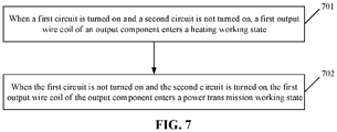
- the embodiment of the present invention also provides an output control method, as shown in FIG. 7 , the method comprises the following steps.
- the first output wire coil of the output component enters a power transmission working state.
- the first circuit is provided with a first switch and is turned on when the first switch is closed
- the second circuit is provided with a second switch and is turned on when the second switch is closed.
- steps 701 and 702 are executed by the processor in the output control device.
- the first switch 302 and the second switch 303 may be circuit switches having both closed and open states.
- the processor determines that the first circuit is connected to the output component, and controls the first output wire coil in the output component to be in the heating working state.
- the processor determines that the second circuit is connected to the output component, and controls the first output wire coil in the output component to be in the power transmission working state.
- the first output wire coil may be an operation wire reel constituted by at least one wire coil.
- the operation wire reel may generate an alternating magnetic field with a constantly changing direction, and the conductor is warmed up through the Joule heating effect, thereby realizing the heating function.
- the above operation wire reel may generate an induced magnetic flux for power transmission.
- the operation that when the first circuit is turned on and the second circuit is not turned on, the output component enters the heating working state comprises the following operations.
- the first output wire coil enters a first heating working state in which a first output power interval is adopted for heating.
- the first output wire coil enters a second heating working state in which a second output power interval is adopted for heating.
- the first output wire coil enters a third heating working state in which a third output power interval is adopted for heating.
- the first sub-circuit is provided with a first sub-switch and is turned on when the first sub-switch is closed.
- the second sub-circuit is provided with a second sub-switch and is turned on when the second sub-switch is closed.
- the first sub-circuit is constituted by the first sub-switch and a first sub-capacitor
- the second sub-circuit is constituted by the second sub-switch and a second sub-capacitor.
- the capacitance of the first sub-capacitor and the capacitance of the second sub-capacitor are different.
- the powers of the first output power interval, the second output power interval and the third power interval are different.
- the first output power interval may be 1kW-3kW
- the second output power interval may be 100W-1kW
- the third output power range may be 1.5 kW-3.3 kW.
- the processor determines that the first sub-capacitor acts on the output component 301, and controls the first output wire coil in the output component to heat the target object with a power in the first output power interval.
- the processor determines that the second sub-capacitor acts on the output component 301, and controls the first output wire coil in the output component to heat the target object with a power in the second output power interval.
- the processor determines that the first sub-capacitor and the second sub-capacitor acts on the output component 301 in parallel, such that the first output wire coil in the output component heats the target object with a power in the third output power interval.
- the processor determines that the second circuit acts on the output component 301, such that the first output wire coil in the output component enters the power transmission working state to transmit power to the target objects.
- the processor determines that the first output wire coil of the output component enters the heating working state or the power transmission working state based on a control instruction.
- the output control method provided in an embodiment of the present invention may comprise an output component, a first switch and a second switch.
- the output component comprises a first output wire coil, and is configured to control the first output wire coil to enter a heating working state when a first circuit is turned on and a second circuit is not turned on, and to control the first output wire coil to enter a power transmission working state when the first circuit is not turned on and the second circuit is turned on.
- the first switch is located in the first circuit and is configured to turn on the first circuit when being closed.
- the second switch is located in the second circuit and is configured to turn on the second circuit when being closed.
- the heating function and the power transmission function are integrated in the same device via the output component, the first switch and the second switch, and the switching between the heating working state and the power transmission working state is realized through the closed or open state of the first switch and the second switch.
- the utilization rate and intelligent degree of the device are improved, and the users' experience is enhanced.
- an embodiment of the present invention also provides a computer readable storage medium, for example, a memory comprising a computer program executable by a processor of an output control device to implement the steps of the aforementioned method.
- the computer readable storage medium may be ferromagnetic random access memory (FRAM), read only memory (ROM), programmable read-only memory (PROM), erasable programmable read-only memory (EPROM), electrically erasable programmable read-only memory (EEPROM), flash memory, magnetic surface memory, compact disc, or compact disc read-only memory (CD-ROM).
- FRAM ferromagnetic random access memory
- ROM read only memory
- PROM programmable read-only memory
- EPROM erasable programmable read-only memory
- EEPROM electrically erasable programmable read-only memory
- flash memory magnetic surface memory, compact disc, or compact disc read-only memory (CD-ROM).
- embodiments of the present invention may be provided as methods, systems or computer program products. Therefore, the present invention may take the form of a hardware embodiment, a software embodiment or an embodiment combining software and hardware aspects. Further, the present invention may take the form of a computer program product implemented on one or more computer-usable storage media (including, but not limited to, disk storage, optical storage, etc.) containing computer-usable program code therein.
- a computer-usable storage media including, but not limited to, disk storage, optical storage, etc.
- each flow and/or block in the flow diagrams and/or block diagrams, as well as combinations of the flow and/or block in the flow diagrams and/or block diagrams, may be implemented by computer program instructions.
- These computer program instructions may be provided to a processor of a general purpose computer, a special purpose computer, an embedded processor, or other programmable data processing device to generate a machine, such that instructions executed by a processor of a computer or other programmable data processing device generate a device for implementing the functions specified in one or more flows of the flow diagrams and/or one or more blocks of the block diagrams.
- These computer program instructions may also be stored in a computer readable memory that directs a computer or other programmable data processing device to operate in a specific manner, such that the instructions stored in the computer readable memory generate an article of manufacture comprising instruction device.
- the instruction device implements the functions specified in one or more flows of the flow diagrams and/or one or more blocks of the block diagrams.
- These computer program instructions may also be loaded onto a computer or other programmable data processing device, such that a series of operational steps are executed on the computer or other programmable device to produce computer-implemented processes, such that instructions executed on the computer or other programmable device provide steps for implementing the functions specified in one or more flows of the flow diagrams and/or one or more blocks of the block diagrams.
Landscapes
- Engineering & Computer Science (AREA)
- Physics & Mathematics (AREA)
- Electromagnetism (AREA)
- Power Engineering (AREA)
- Computer Networks & Wireless Communication (AREA)
- Signal Processing (AREA)
- Transportation (AREA)
- Mechanical Engineering (AREA)
- General Induction Heating (AREA)
Abstract
Description
- The present invention relates to the technical field of electronic control, in particular to an output control device and method, and a storage medium.
- With the increasing popularity of electric heating technology and the rapid development of wireless charging technology, a variety of heating devices and wireless power transmission devices are constantly emerging, which has brought great convenience to people's lives. However, due to the different working properties of heating technology and wireless power transmission technology, at present, electric heating devices used to heat objects can only be used for heating but cannot carry out wireless power transmission, such as induction cookers and other heating devices. Moreover, high-power transmission device can only be used for wireless power transmission but cannot be used for heating objects, such as automobile wireless charging devices. Therefore, when using the heating function and the wireless charging function, the user needs to select a device with corresponding function, so that the utilization rate, intelligence and user experience of the device are low. Therefore, how to combine the heating function with the wireless power transmission function so as to improve the utilization rate of the device is an urgent problem to be solved.
- In order to solve the above technical problems, it is desirable for the embodiments of the present invention to provide an output control device, an output control method and a computer storage medium.
- The technical solution of the invention is realized as follows.
- According to a first aspect, there is provided an output control device comprising: an output component, a first switch and a second switch.
- The output component comprises a first output wire coil, and is configured to control the first output wire coil to enter a heating working state when a first circuit is turned on and a second circuit is not turned on; and to control the first output wire coil to enter a power transmission working state when the first circuit is not turned on and the second circuit is turned on.
- The first switch is located in the first circuit and is configured to turn on the first circuit when being closed.
- The second switch is located in the second circuit and is configured to turn on the second circuit when being closed.
- According to a second aspect, there is provided an output control method comprising the following operations.
- When a first circuit is turned on and a second circuit is not turned on, a first output wire coil of an output component enters a heating working state.
- When the first circuit is not turned on and the second circuit is turned on, the first output wire coil of the output component enters a power transmission working state.
- The first circuit is provided with a first switch and is turned on when the first switch is closed. The second circuit is provided with a second switch and is turned on when the second switch is closed.
- According to a third aspect, there is provided a computer-readable storage medium. The computer-readable storage medium stores one or more programs executable by one or more processors to implement the steps of the output control method according to the second aspect.
- The output control device, the output control method and the computer storage medium provided in the embodiments of the present invention may comprise an output component, a first switch and a second switch. The output component comprises a first output wire coil, and is configured to control the first output wire coil to enter a heating working state when a first circuit is turned on and a second circuit is not turned on; and to control the first output wire coil to enter a power transmission working state when the first circuit is not turned on and the second circuit is turned on. The first switch is located in the first circuit and is configured to turn on the first circuit when being closed; and the second switch is located in the second circuit and is configured to turn on the second circuit when being closed. In this way, the heating function and the power transmission function are integrated in the same device through the output component, the first switch and the second switch, and the switching between the heating working state and the power transmission working state is realized through the closed or open state of the first switch and the second switch. As such, the utilization rate and intelligence degree of the device are improved, and the users' experience is enhanced.
-
-
FIG. 1 is a schematic view of a circuit topology of a heating device provided by an embodiment of the present invention; -
FIG. 2 is a schematic view of a circuit topology of a wireless power transmission device provided by an embodiment of the present invention; -
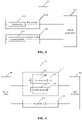
FIG. 3 is a schematic structural view of an output control device provided by an embodiment of the present invention; -
FIG. 4 is a schematic structural view of another output control device provided by an embodiment of the present invention; -
FIG. 5 is a schematic view of a circuit topology of an output control device provided by an embodiment of the present invention; -
FIG. 6 is a schematic view of a circuit topology of another output control device provided by an embodiment of the present invention; -
FIG. 7 is flow diagram of an output control method provided by an embodiment of the present invention. - The technical solution in the embodiments of the invention will be clearly and completely described below with reference to the drawings in the embodiments of the invention.
- In practical use, the circuit topology of the heating device may be shown in
FIG. 1 , theheating device 10 specifically comprises aninverter bridge circuit 101, acapacitor 102 and aheating wire reel 103. The capacitor may be a compensation capacitor. The heating device makes the heating wire reel generate an alternating magnetic field with a constantly changing direction through the inverter bridge circuit, and eddy current will appear inside a conductor located in the alternating magnetic field, the conductor is warmed up through the Joule heating effect of the eddy current, thereby realizing the heating. - In addition, the circuit topology of the wireless power transmission device in the prior art is shown in
FIG. 2 . The wirelesspower transmission device 20 specifically comprises aninverter bridge circuit 201, aninductor 202, aresonant capacitor 203, acapacitor 204, and a powertransmission wire reel 205. Theinductor 202 may be a compensation/filter/bandpass inductor, and thecapacitor 204 may be a compensation/ oscillation capacitor. Herein, the wireless power transmission device is connected by the circuit shown inFIG. 2 , such that the power transmission wire reel generates an induced magnetic flux to transmit power. - As can be seen from the schematic view of the circuit topology in
FIG. 1 and FIG. 2 , the working property of the heating device is different from the working property of the power transmission device. At present, the heating device and the power transmission device are both single entities, the heating device cannot realize the power transmission function, and the power transmission device cannot heat objects. Therefore, when using the heating function and the wireless charging function, the user needs to select the device with corresponding function, and thus the utilization rate, intelligence and user experience of the device are low. - Based on the above problems, the embodiment of the present invention provides an output control device. Referring to
FIG. 3 , theoutput control device 30 comprises: anoutput component 301, afirst switch 302 and asecond switch 303. - The
output component 301 comprises a first output wire coil, and the output component is configured to control the first output wire coil to enter a heating working state when a first circuit is turned on and a second circuit is not turned on; and to control the first output wire coil to enter a power transmission working state when the first circuit is not turned on and the second circuit is turned on. - The
first switch 302 is located in the first circuit and is configured to turn on the first circuit when being closed. - The
second switch 302 is located in the second circuit and is configured to turn on the second circuit when being closed. - In other embodiments of the invention, the output control device further comprises a
first circuit 304, asecond circuit 305 and aninverter circuit 306. Specifically, theoutput component 301 is connected to a first end of thefirst circuit 304 and a first end of thesecond circuit 305, respectively. A second end of thefirst circuit 304 and a second end of thesecond circuit 305 are connected to theinverter circuit 306. Here, theinverter circuit 306 may provide alternating current to the output device via the first circuit or the second circuit. In this embodiment, theinverter circuit 306 is preferably an inverter bridge circuit. - In other embodiments of the present invention, the
first switch 302 and thesecond switch 303 may be circuit switches having both closed and open states. When the first switch is closed and the second switch is opened, the first circuit is turned on and the second circuit is not turned on. At this time, theinverter circuit 306 is connected to the output component via the first circuit, and the output component controls the first output wire coil to be in the heating working state through the connection of the first circuit. When the first switch is opened and the second switch is closed, the first circuit is not turned on and the second circuit is turned on. At this time, theinverter circuit 306 is connected to the output component via the second circuit, and the output component controls the first output wire coil to be in the power transmission working state through the connection of the second circuit. - Further, the output component comprises a first output wire coil, which may be an operation wire reel constituted by at least one wire coil. Under the condition that the first circuit is turned on and the second circuit is not turned on, the operation wire reel may generate an alternating magnetic field with a constantly changing direction, and the conductor is warmed up through the Joule heating effect, thereby realizing the heating function. In addition, under the condition that the first circuit is not turned on and the second circuit is turned on, the above operation wire reel can generate an induced magnetic flux for power transmission.
- Based on the foregoing embodiments, in another embodiment of the present invention, as shown in
FIG. 4 , thefirst switch 302 further comprises a first sub-switch 401 and asecond sub-switch 402. - Specifically, the first sub-switch 401 is located in a
first sub-circuit 403 and is configured to turn on the first sub-circuit when being closed; and thesecond sub-switch 402 is located in asecond sub-circuit 404 and is configured to turn on the second sub-circuit when being closed. The first sub-circuit and/or the second sub-circuit may constitute thefirst circuit 304. - In other embodiments of the invention, the output control device further comprises an
inverter circuit 306. Specifically, theoutput component 301 is connected to the first end of thefirst circuit 304 and the first end of thesecond circuit 305, respectively. The second end of thefirst circuit 304 and the second end of thesecond circuit 305 are connected to theinverter circuit 306. Here, theinverter circuit 306 may provide an alternating current to the output device via the first circuit or the second circuit. In this embodiment, theinverter circuit 306 is preferably an inverter bridge circuit. - Here, the first sub-switch and the second sub-switch each may be a circuit switch, and the first sub-circuit and the second sub-circuit can be connected in parallel. When the first sub-circuit is turned on and the second sub-circuit is not turned on, the first circuit is constituted by the first sub-circuit. When the first sub-circuit is not turned on and the second sub-circuit is turned on, the first circuit is constituted by the second sub-circuit. When the first sub-circuit and the second sub-circuit are simultaneously turned on, the first circuit is constituted by the first sub-circuit and the second sub-circuit.
- In other embodiments of the present invention, when the first sub-circuit is turned on and the second sub-circuit is not turned on, the first output wire coil is controlled to enter a first heating working state in which a first output power interval is adopted for heating.
- When the second sub-circuit is turned on and the first sub-circuit is not turned on, the first output wire coil is controlled to enter a second heating working state in which a second output power interval is adopted for heating.
- When the first sub-circuit is turned on and the second sub-circuit is turned on, the first output wire coil is controlled to enter a third heating working state in which a third output power interval is adopted for heating.
- Specifically, the first sub-circuit is constituted by the first sub-switch and the first sub-capacitor, and the second sub-circuit is constituted by the second sub-switch and the second sub-capacitor. The capacitance of the first sub-capacitor and the capacitance of the second sub-capacitor are different. The powers of the first output power interval, the second output power interval and the third power interval are different. Exemplarily, the first output power interval may be 1kW-3kW, the second output power interval may be 100W-1kW, and the third output power interval may be 1.5 kW-3.3 kW.
- In this way, under the condition that the first sub-circuit is turned on, the second sub-circuit is not turned on and the second circuit is not turned on (that is, the first sub-switch is closed, the second sub-switch is not closed and the second switch is not closed), the first sub-capacitor in the first sub-circuit is in an working state, and the alternating current output by the
inverter circuit 306 acts on the first output wire coil in theoutput component 301 via the first sub-capacitor, such that the first output wire coil heats the target object in the first output power interval. - In addition, under the condition that the first sub-circuit is not turned on, the second sub-circuit is turned on and the second circuit is not turned on (that is, the first sub-switch is not closed, the second sub-switch is closed and the second switch is not closed), the second sub-capacitor in the second sub-circuit is in an working state, and the alternating current output by the
inverter circuit 306 acts on the first output wire coil in theoutput component 301 via the second sub-capacitor, such that the first output wire coil heats the target object in the second output power interval. - Further, under the condition that both the first sub-circuit and the second sub-circuit are turned on, and the second circuit is not turned on (that is, both the first sub-switch and the second sub-switch are closed, and the second switch is not closed), the alternating current output by the
inverter circuit 306 is acted on the first output wire coil in theoutput component 301 via the first sub-capacitor and the second sub-capacitor in parallel, such that the first output wire coil heats the target object in the third output power interval. - Finally, under the condition that neither the first sub-circuit nor the second sub-circuit is turned on, and the second circuit is turned on (that is, neither the first sub-switch nor the second sub-switch is closed, and the second switch is closed), the alternating current output by the
inverter circuit 306 acts on the first output wire coil in theoutput component 301 via the second circuit, such that the first output wire coil enters the power transmission working state for transmitting power to the target object. - The output control device provided by the embodiments of the present invention integrates the heating function and the power transmission function in the same device via the output component, the first switch and the second switch. The heating function and the power transmission function share the same first output wire coil, and the switching between the heating working state and the power transmission working state is realized through the closed or open state of the first switch and the second switch. As such, the utilization rate and the intelligent degree of the device are improved, and the users' experience is enhanced.
- Based on the foregoing embodiments, an embodiment of the present invention provides an output control device. Referring to
FIG. 5 , the device comprises: anoutput component 501, afirst switch 502 and asecond switch 503. - The
output component 501 comprises a first output wire coil, and is configured to control the first output wire coil to enter a heating working state when a first circuit is turned on and a second circuit is not turned on, and to control the first output wire coil to enter a power transmission working state when the first circuit is not turned on and the second circuit is turned on. - The
first switch 502 is located in the first circuit and is configured to turn on the first circuit when being closed. - The
second switch 503 is located in the second circuit and is configured to turn on the second circuit when being closed. - The output device further comprises an
inverter bridge circuit 504, to supply an alternating current to the first output wire coil in theoutput component 501. - In other embodiments of the present invention, the output control device further comprises: a
first inductor 505 and/or afirst capacitor 506. Thefirst inductor 505 and/or thefirst capacitor 506 are arranged in the second circuit. The first inductor may be a compensation/filter/bandpass inductor. In addition, the output control device further comprises: asecond capacitor 507, athird capacitor 508 and afourth capacitor 509. Thesecond capacitor 507 and thethird capacitor 508 are arranged in the second circuit. Thefourth capacitor 509 is a capacitor shared by the first circuit and the second circuit and is arranged in the first circuit and the second circuit. - The connection of individual components is described in detail below.
- Specifically, when the output control device comprises the
first inductor 505 or thefirst capacitor 506, a first end of theinverter bridge circuit 504 is connected to a first end of thefirst inductor 505/thefirst capacitor 506 and a first end of thefirst switch 502, respectively; and a second end of thefirst inductor 505/thefirst capacitor 506 is connected to a first end of thesecond switch 503 and a first end of thethird capacitor 508, respectively. A second end of thesecond switch 503 is connected to a first end of thesecond capacitor 507, and a second end of thesecond capacitor 507 is connected to a second end of theinverter bridge circuit 504 and a second end of theoutput component 501. Further, a second end of thethird capacitor 508 is connected to a second end of thefirst switch 502 and a first end of thefourth capacitor 509, respectively. In addition, a second end of thefourth capacitor 509 is connected to a first end of theoutput component 501. - Moreover, when the output control device comprises the
first inductor 505 and thefirst capacitor 506, thefirst inductor 505 and thefirst capacitor 506 are connected in series. Specifically, as shown inFIG. 5 , the first end of theinverter bridge circuit 504 is connected to the first end of thefirst capacitor 506 and the first end of thefirst switch 502, respectively; the second end of thefirst capacitor 506 is connected to the first end of thefirst inductor 505; the second end of thefirst inductor 505 is connected to the first end of thesecond switch 503 and the first end of thethird capacitor 508, respectively; the second end of thesecond switch 503 is connected to the first end of thesecond capacitor 507, and the second end of thesecond capacitor 507 is connected to the second end of theinverter bridge circuit 504 and the second end of theoutput component 501. Further, the second end of the third capacitor is connected to the second end of thefirst switch 502 and the first end of thefourth capacitor 509, respectively. In addition, the second end of thefourth capacitor 509 is connected to the first end of theoutput component 501. - As can be seen from
FIG. 5 , when thefirst switch 502 is closed and thesecond switch 503 is not closed, the circuit topology is similar to that shown inFIG. 1 . Therefore, when thefirst switch 502 is closed and thesecond switch 503 is not closed, the first output wire coil in the output component is in the heating working state. In addition, when thefirst switch 502 is not closed and thesecond switch 503 is closed, the circuit topology is similar to the topology structure shown inFIG. 2 . Therefore, when thefirst switch 502 is not closed and thesecond switch 503 is closed, the first output wire coil in the output component is in the power transmission working state. - Based on the foregoing embodiments, in another embodiment of the present invention, as shown in
FIG. 6 , thefirst switch 502 further comprises a first sub-switch 601 and a second sub-switch 602. The first sub-switch 601 is located in a first sub-circuit and is configured to turn on the first sub-circuit when being closed. The second sub-switch 602 is located in a second sub-circuit and is configured to turn on the second sub-circuit when being closed. The first sub-circuit and/or the second sub-circuit may constitute the first circuit. The output control device further comprises afifth capacitor 603 and asixth capacitor 604. Thefifth capacitor 603 is arranged in the first sub-circuit, and thesixth capacitor 604 is a capacitor shared by the second sub-circuit and the second circuit. - Specially, as shown in
FIG. 6 , the first end of theinverter bridge circuit 504 is connected to the first end of thefirst capacitor 506, a first end of the first sub-switch 601 and a first end of the second sub-switch 602, respectively; the second end of thefirst capacitor 506 is connected to the first end of thefirst inductor 505; the second end of thefirst inductor 505 is connected to the first end of thesecond switch 503 and the first end of thethird capacitor 508, respectively; the second end of thesecond switch 503 is connected to the first end of thesecond capacitor 507, and the second end of thesecond capacitor 507 is connected to the second end of theinverter bridge circuit 504 and the second end of theoutput component 501. Further, the second end of thethird capacitor 508 is connected to a second end of the second sub-switch 602 and a first end of thesixth capacitor 604, respectively. In addition, a second end of thesixth capacitor 604 is connected to the first end of theoutput component 501 and a second end of thefifth capacitor 603, respectively. A second end of the first sub-switch 601 is connected to a first end of thefifth capacitor 603. - In this way, in the circuit topology shown in
FIG. 6 , under the condition that the first sub-switch 601 is closed, the second sub-switch 602 is not closed and thesecond switch 503 is closed, thefifth capacitor 603 is in an working state, and the alternating current output by theinverter circuit 504 acts on theoutput component 501 via thefifth capacitor 603, such that the first output wire coil in the output component heats the target object with a power in the first output power interval. Under the condition that the first sub-switch 601 is not closed, the second sub-switch 602 is closed and thesecond switch 503 is closed, thesixth capacitor 604 is in an working state, and the alternating current output by theinverter circuit 504 acts on theoutput component 501 via thesixth capacitor 604, such that the first output wire coil in the output component heats the target object with a power in the second output power interval. - In addition, under the condition that both the first sub-switch 601 and the second sub-switch 602 are closed, and the
second switch 503 is not closed, the alternating current output by theinverter circuit 504 is acted on theoutput component 501 via thefifth capacitor 603 and thesixth capacitor 604 in parallel, such that the first output wire coil in the output component heats the target object with a power in the third output power interval. Under the condition that neither the first sub-switch 601 nor the second sub-switch 602 is closed and thesecond switch 503 is closed, the alternating current output by theinverter circuit 504 acts on theoutput component 501 via thefirst capacitor 506, thefirst inductor 505, thesecond capacitor 507, thethird capacitor 508 and thesixth capacitor 604, such that the first output wire coil in the output component enters the power transmission working state to transmit power to the target object. - In another embodiment, the output device further comprises a processor, which is configured to determine that the first output wire coil of the output component enters the heating working state or the power transmission working state based on a control instruction.
- Here, the control instruction may be a working state switching instruction input by a user. Generally, the output control device can provide buttons with different functions on the outermost side, for example, power transmission mode button and heating mode button. The processor may determine based on the control instruction the working state that the output control device will enter.
- Specifically, the output control device may further comprise a memory, and a controller switches the working state of the output device based on the software program stored in the memory. In particular, when it is determined that the first output wire coil of the output component enters the heating working state, the first switch is controlled to be closed and the second switch is controlled not to be closed; and when it is determined that the first output wire coil of the output component enters the power transmission working state, the second switch is controlled to be closed and the first switch is controlled not to be closed.
- It should be noted that the same steps and contents in this embodiment as in other embodiments can be described with reference to other embodiments and will be not repeatedly described here.
- The output control device provided in the embodiment of the present invention may comprise an output component, a first switch and a second switch. The output component comprises a first output wire coil, and is configured to control the first output wire coil to enter a heating working state when a first circuit is turned on and a second circuit is not turned on, and to control the first output wire coil to enter a power transmission working state when the first circuit is not turned on and the second circuit is turned on. The first switch is located in the first circuit and is configured to turn on the first circuit when being closed. The second switch is located in the second circuit and is configured to turn on the second circuit when being closed. In this way, the heating function and the power transmission function are integrated in the same device via the output component, the first switch and the second switch, and the switching between the heating working state and the power transmission working state is realized through the closed or open state of the first switch and the second switch. As such, the utilization rate and intelligent degree of the device are improved, and the users' experience is enhanced.
- Based on the above output control device, the embodiment of the present invention also provides an output control method, as shown in
FIG. 7 , the method comprises the following steps. - At 701, when a first circuit is turned on and a second circuit is not turned on, a first output wire coil of an output component enters a heating working state.
- At 702, when the first circuit is not turned on and the second circuit is turned on, the first output wire coil of the output component enters a power transmission working state.
- The first circuit is provided with a first switch and is turned on when the first switch is closed, and the second circuit is provided with a second switch and is turned on when the second switch is closed.
- Here, the
steps - Specifically, the
first switch 302 and thesecond switch 303 may be circuit switches having both closed and open states. When the first switch is closed and the second switch is opened, the first circuit is turned on and the second circuit is not turned on. At this time, the processor determines that the first circuit is connected to the output component, and controls the first output wire coil in the output component to be in the heating working state. When the first switch is opened and the second switch is closed, the first circuit is not turned on and the second circuit is turned on. At this time, the processor determines that the second circuit is connected to the output component, and controls the first output wire coil in the output component to be in the power transmission working state. - Further, the first output wire coil may be an operation wire reel constituted by at least one wire coil. Under the condition that the first circuit is turned on and the second circuit is not turned on, the operation wire reel may generate an alternating magnetic field with a constantly changing direction, and the conductor is warmed up through the Joule heating effect, thereby realizing the heating function. In addition, under the condition that the first circuit is not turned on and the second circuit is turned on, the above operation wire reel may generate an induced magnetic flux for power transmission.
- Specifically, the operation that when the first circuit is turned on and the second circuit is not turned on, the output component enters the heating working state, comprises the following operations.
- When a first sub-circuit is turned on and a second sub-circuit is not turned on, the first output wire coil enters a first heating working state in which a first output power interval is adopted for heating.
- When the second sub-circuit is turned on and the first sub-circuit is not turned on, the first output wire coil enters a second heating working state in which a second output power interval is adopted for heating.
- When the first sub-circuit is turned on and the second sub-circuit is turned on, the first output wire coil enters a third heating working state in which a third output power interval is adopted for heating.
- The first sub-circuit is provided with a first sub-switch and is turned on when the first sub-switch is closed.
- The second sub-circuit is provided with a second sub-switch and is turned on when the second sub-switch is closed.
- Specifically, the first sub-circuit is constituted by the first sub-switch and a first sub-capacitor, and the second sub-circuit is constituted by the second sub-switch and a second sub-capacitor. The capacitance of the first sub-capacitor and the capacitance of the second sub-capacitor are different. The powers of the first output power interval, the second output power interval and the third power interval are different. Exemplarily, the first output power interval may be 1kW-3kW; the second output power interval may be 100W-1kW; the third output power range may be 1.5 kW-3.3 kW.
- In this way, under the condition that the first sub-circuit is turned on, the second sub-circuit is not turned on and the second circuit is not turned on (that is, the first sub-switch is closed, the second sub-switch is not closed and the second switch is not closed), the first sub-capacitor in the first sub-circuit is in an working state, the processor determines that the first sub-capacitor acts on the
output component 301, and controls the first output wire coil in the output component to heat the target object with a power in the first output power interval. - In addition, under the condition that the first sub-circuit is not turned on, the second sub-circuit is turned on and the second circuit is not turned on (that is, the first sub-switch is not closed, the second sub-switch is closed and the second switch is not closed), the second sub-capacitor in the second sub-circuit is in an working state, the processor determines that the second sub-capacitor acts on the
output component 301, and controls the first output wire coil in the output component to heat the target object with a power in the second output power interval. - Further, under the condition that both the first sub-circuit and the second sub-circuit are turned on, and the second circuit is not turned on (that is, both the first sub-switch and the second sub-switch are closed, and the second switch is not closed), the processor determines that the first sub-capacitor and the second sub-capacitor acts on the
output component 301 in parallel, such that the first output wire coil in the output component heats the target object with a power in the third output power interval. - Finally, under the condition that neither the first sub-circuit nor the second sub-circuit is turned on, and the second circuit is turned on (that is, neither the first sub-switch nor the second sub-switch is closed, and the second switch is closed), the processor determines that the second circuit acts on the
output component 301, such that the first output wire coil in the output component enters the power transmission working state to transmit power to the target objects. - In other embodiments of the present invention, the following operation is further comprised.
- The processor determines that the first output wire coil of the output component enters the heating working state or the power transmission working state based on a control instruction.
- It should be noted that the same steps and contents in this embodiment as in other embodiments can be described with reference to other embodiments and will be not repeatedly described here.
- The output control method provided in an embodiment of the present invention may comprise an output component, a first switch and a second switch. The output component comprises a first output wire coil, and is configured to control the first output wire coil to enter a heating working state when a first circuit is turned on and a second circuit is not turned on, and to control the first output wire coil to enter a power transmission working state when the first circuit is not turned on and the second circuit is turned on. The first switch is located in the first circuit and is configured to turn on the first circuit when being closed. The second switch is located in the second circuit and is configured to turn on the second circuit when being closed. In this way, the heating function and the power transmission function are integrated in the same device via the output component, the first switch and the second switch, and the switching between the heating working state and the power transmission working state is realized through the closed or open state of the first switch and the second switch. As such, the utilization rate and intelligent degree of the device are improved, and the users' experience is enhanced.
- In an exemplary embodiment, an embodiment of the present invention also provides a computer readable storage medium, for example, a memory comprising a computer program executable by a processor of an output control device to implement the steps of the aforementioned method. The computer readable storage medium may be ferromagnetic random access memory (FRAM), read only memory (ROM), programmable read-only memory (PROM), erasable programmable read-only memory (EPROM), electrically erasable programmable read-only memory (EEPROM), flash memory, magnetic surface memory, compact disc, or compact disc read-only memory (CD-ROM).
- Those skilled in the art should understand that embodiments of the present invention may be provided as methods, systems or computer program products. Therefore, the present invention may take the form of a hardware embodiment, a software embodiment or an embodiment combining software and hardware aspects. Further, the present invention may take the form of a computer program product implemented on one or more computer-usable storage media (including, but not limited to, disk storage, optical storage, etc.) containing computer-usable program code therein.
- The present invention is described with reference to flow diagrams and/or block diagrams of methods, devices (systems), and computer program products according to embodiments of the present invention. It should be understood that each flow and/or block in the flow diagrams and/or block diagrams, as well as combinations of the flow and/or block in the flow diagrams and/or block diagrams, may be implemented by computer program instructions. These computer program instructions may be provided to a processor of a general purpose computer, a special purpose computer, an embedded processor, or other programmable data processing device to generate a machine, such that instructions executed by a processor of a computer or other programmable data processing device generate a device for implementing the functions specified in one or more flows of the flow diagrams and/or one or more blocks of the block diagrams.
- These computer program instructions may also be stored in a computer readable memory that directs a computer or other programmable data processing device to operate in a specific manner, such that the instructions stored in the computer readable memory generate an article of manufacture comprising instruction device. The instruction device implements the functions specified in one or more flows of the flow diagrams and/or one or more blocks of the block diagrams.
- These computer program instructions may also be loaded onto a computer or other programmable data processing device, such that a series of operational steps are executed on the computer or other programmable device to produce computer-implemented processes, such that instructions executed on the computer or other programmable device provide steps for implementing the functions specified in one or more flows of the flow diagrams and/or one or more blocks of the block diagrams.
- The above description is only preferred embodiments of the present invention and is not intended to limit the scope of protection of the present invention.
Claims (10)
- An output control device, characterised in that the output control device comprises: an output component, a first switch and a second switch; wherein,the output component comprises a first output wire coil, and is configured to control the first output wire coil to enter a heating working state when a first circuit is turned on and a second circuit is not turned on and to control the first output wire coil to enter a power transmission working state when the first circuit is not turned on and the second circuit is turned on;the first switch is located in the first circuit and is configured to turn on the first circuit when being closed;the second switch is located in the second circuit and is configured to turn on the second circuit when being closed.
- The device according to claim 1, characterised in that the first switch comprises: a first sub-switch and a second sub-switch; wherein,the first sub-switch is located in a first sub-circuit and is configured to turn on the first sub-circuit when being closed; andthe second sub-switch is located in a second sub-circuit and is configured to turn on the second sub-circuit when being closed;wherein the first sub-circuit and/or the second sub-circuit constitute the first circuit.
- The device according to claim 2, characterised in that the output component is configured to execute one of the following operations:when the first sub-circuit is turned on and the second sub-circuit is not turned on, the first output wire coil is controlled to enter a first heating working state in which a first output power interval is adopted for heating;when the second sub-circuit is turned on and the first sub-circuit is not turned on, the first output wire coil is controlled to enter a second heating working state in which a second output power interval is adopted for heating; orwhen the first sub-circuit is turned on and the second sub-circuit is turned on, the first output wire coil is controlled to enter a third heating working state in which a third output power interval is adopted for heating.
- The device according to claim 1, characterised in that the device further comprises: a first inductor and/or a first capacitor;
wherein the first inductor and/or the first capacitor are arranged in the second circuit. - The device according to any one of claims 1 to 4, characterised in that the device further comprises:
a processor, configured to determine that the first output wire coil of the output component enters the heating working state or the power transmission working state based on a control instruction. - The device according to claim 5, characterised in thatthe processor is configured to control the first switch to be closed and the second switch not to be closed when it is determined that the first output wire coil of the output component enters the heating working state; andto control the second switch to be closed and the first switch not to be closed when it is determined that the first output wire coil of the output component enters the power transmission working state.
- An output control method, characterised in that the output control method comprises:controlling a first output wire coil of an output component to enter a heating working state when a first circuit is turned on and a second circuit is not turned on; andcontrolling the first output wire coil of the output component to enter a power transmission working state when the first circuit is not turned on and the second circuit is turned on;wherein the first circuit is provided with a first switch and is turned on when the first switch is closed; and the second circuit is provided with a second switch and is turned on when the second switch is closed.
- The method according to claim 7, characterised in that said controlling a first output wire coil of an output component to enter a heating working state when a first circuit is turned on and a second circuit is not turned on comprises the following operations:when a first sub-circuit is turned on and a second sub-circuit is not turned on, the first output coil enters a first heating working state in which a first output power interval is adopted for heating;when a second sub-circuit is turned on and a first sub-circuit is not turned on, the first output wire coil enters a second heating working state in which a second output power interval is adopted for heating;when a first sub-circuit is turned on and a second sub-circuit is turned on, the first output wire coil enters a third heating working state in which a third output power interval is adopted for heating;wherein,the first sub-circuit is provided with a first sub-switch and is turned on when the first sub-switch is closed; andthe second sub-circuit is provided with a second sub-switch and is turned on when the second sub-switch is closed.
- The method according to claim 7 or 8, characterised in that the method further comprises:
determining that the first output wire coil of the output component enters the heating working state or the power transmission working state based on a control instruction. - A computer-readable storage medium, characterised in that the computer-readable storage medium stores one or more programs executable by one or more processors to implement the steps of the output control method according to any one of claims 7 to 9.
Applications Claiming Priority (2)
| Application Number | Priority Date | Filing Date | Title |
|---|---|---|---|
| CN201910765738.XA CN112398234A (en) | 2019-08-19 | 2019-08-19 | An output control device, method and storage medium |
| PCT/CN2019/122810 WO2021031450A1 (en) | 2019-08-19 | 2019-12-03 | Output control device and method, and storage medium |
Publications (2)
| Publication Number | Publication Date |
|---|---|
| EP3998692A1 true EP3998692A1 (en) | 2022-05-18 |
| EP3998692A4 EP3998692A4 (en) | 2023-03-22 |
Family
ID=74603563
Family Applications (1)
| Application Number | Title | Priority Date | Filing Date |
|---|---|---|---|
| EP19942614.9A Pending EP3998692A4 (en) | 2019-08-19 | 2019-12-03 | OUTPUT CONTROL DEVICE AND METHOD, AND MEDIA |
Country Status (5)
| Country | Link |
|---|---|
| US (1) | US11791660B2 (en) |
| EP (1) | EP3998692A4 (en) |
| JP (1) | JP7409751B2 (en) |
| CN (1) | CN112398234A (en) |
| WO (1) | WO2021031450A1 (en) |
Family Cites Families (26)
| Publication number | Priority date | Publication date | Assignee | Title |
|---|---|---|---|---|
| US3710062A (en) * | 1971-04-06 | 1973-01-09 | Environment One Corp | Metal base cookware induction heating apparatus having improved power supply and gating control circuit using infra-red temperature sensor and improved induction heating coil arrangement |
| US4792965A (en) * | 1987-01-29 | 1988-12-20 | Morgan Harvey L | Oscillator system for detecting a selected one of a plurality of tuned circuits |
| US9515494B2 (en) | 2008-09-27 | 2016-12-06 | Witricity Corporation | Wireless power system including impedance matching network |
| JP5591810B2 (en) * | 2008-10-01 | 2014-09-17 | レステック リミテッド | Circuit and method for coupling electrical energy to a resonant inductive load |
| ES2356441B1 (en) | 2008-12-19 | 2012-03-13 | Bsh Electrodomésticos España, S.A. | COOKING FIELD WITH AN INDUCTOR, AN INVESTOR AND A CONNECTION DEVICE. |
| JP5419842B2 (en) | 2010-10-06 | 2014-02-19 | 三菱電機株式会社 | Power processing device |
| CN104113143A (en) * | 2013-04-19 | 2014-10-22 | 美的集团股份有限公司 | Wireless electric energy transmission system and control method thereof |
| CN103744492A (en) * | 2013-11-20 | 2014-04-23 | 无锡通明科技有限公司 | Heat dissipation cushion for wireless charging notebook computer |
| JP6328572B2 (en) | 2015-01-22 | 2018-05-23 | 三菱電機株式会社 | Induction heating cooker with non-contact power feeding function and control method thereof |
| CN106162963A (en) * | 2015-04-07 | 2016-11-23 | 佛山市顺德区美的电热电器制造有限公司 | Cooking apparatus and the electric heater unit for cooking apparatus |
| JP6173623B2 (en) | 2015-07-31 | 2017-08-02 | 三菱電機株式会社 | Induction heating cooker and control method thereof |
| JP2017046510A (en) | 2015-08-28 | 2017-03-02 | パナソニックIpマネジメント株式会社 | Cooking system |
| WO2017054228A1 (en) * | 2015-10-01 | 2017-04-06 | 史利利 | Induction stove |
| WO2017082475A1 (en) * | 2015-11-11 | 2017-05-18 | 엘지전자(주) | Wireless power transmission system communication protocol |
| KR101727744B1 (en) * | 2016-02-26 | 2017-04-17 | (주)그린파워 | method for identifying load for operating control of power supply apparatus using as a two-way induction cooker and wireless power transmitting device |
| CN206176478U (en) * | 2016-11-14 | 2017-05-17 | 浙江绍兴苏泊尔生活电器有限公司 | Electromagnetic oven |
| CN106685102A (en) * | 2016-12-19 | 2017-05-17 | 美的集团股份有限公司 | Household electrical appliance, wireless power transmission and electromagnetic heating switching device, and wireless power transmission and electromagnetic heating switching method thereof |
| KR101968553B1 (en) * | 2017-01-04 | 2019-04-12 | 엘지전자 주식회사 | Induction heat cooking apparatus to implement wpt and pfc power converter |
| JP2020512170A (en) | 2017-03-28 | 2020-04-23 | インダクティブ インテリジェンス,リミティド ライアビリティ カンパニー | Smart appliance, system and method |
| US10998822B2 (en) * | 2017-05-26 | 2021-05-04 | General Electric Company | Power transfer device with a plurality of converters |
| EP3474629B1 (en) * | 2017-10-19 | 2020-12-02 | LG Electronics Inc. -1- | Induction heating and wireless power transferring device having improved resonant current detection accuracy |
| EP3474630B1 (en) | 2017-10-19 | 2024-06-26 | LG Electronics Inc. | Induction heating device having improved target object detection accuracy and induction heating system including the same |
| KR102040221B1 (en) * | 2017-12-20 | 2019-11-04 | 엘지전자 주식회사 | Induction heating device having improved interference noise canceling function and power control function |
| KR102101898B1 (en) * | 2018-05-16 | 2020-05-29 | 엘지전자 주식회사 | Induction heating device having improved control algorithm and circuit structure |
| CN109567276B (en) * | 2018-11-30 | 2023-12-01 | 深圳华大北斗科技股份有限公司 | Non-contact heating element and electron cigarette |
| KR102889478B1 (en) * | 2020-02-18 | 2025-11-20 | 엘지전자 주식회사 | Wireless power transfer apparatus, wireless power reception apparatus, and system including the same |
-
2019
- 2019-08-19 CN CN201910765738.XA patent/CN112398234A/en active Pending
- 2019-12-03 WO PCT/CN2019/122810 patent/WO2021031450A1/en not_active Ceased
- 2019-12-03 EP EP19942614.9A patent/EP3998692A4/en active Pending
- 2019-12-03 JP JP2022511093A patent/JP7409751B2/en active Active
-
2022
- 2022-02-17 US US17/674,208 patent/US11791660B2/en active Active
Also Published As
| Publication number | Publication date |
|---|---|
| CN112398234A (en) | 2021-02-23 |
| EP3998692A4 (en) | 2023-03-22 |
| US11791660B2 (en) | 2023-10-17 |
| WO2021031450A1 (en) | 2021-02-25 |
| JP7409751B2 (en) | 2024-01-09 |
| US20220173621A1 (en) | 2022-06-02 |
| JP2022545004A (en) | 2022-10-24 |
Similar Documents
| Publication | Publication Date | Title |
|---|---|---|
| KR102031875B1 (en) | Induction heat cooking apparatus and method for controlling of output level the same | |
| US10897374B2 (en) | Scalable smart environment for controlling a plurality of controlled apparatuses using a connection hub to route a processed subset of control data received from a cloud computing resource to terminal units | |
| CN105532073A (en) | A method and device for determining the suitability of a cookware for a corresponding induction coil of an induction cooking hob | |
| KR102031907B1 (en) | Induction heat cooking apparatus and method for controlling of output level the same | |
| US20220170966A1 (en) | Detection Circuit, Appliance and Control Method | |
| US11791660B2 (en) | Output control device for controlling an operation mode of a coil | |
| EP3509399A1 (en) | Induction heating cooker | |
| CN108506969A (en) | A kind of control method of gas-cooker and a kind of gas-cooker | |
| CN113271696B (en) | Electromagnetic induction heating circuit, control method thereof and electromagnetic heating equipment | |
| CN105376915B (en) | A kind of non-contact switch | |
| CN102256401A (en) | Multi-coil electromagnetic heating system and method | |
| KR102097430B1 (en) | Induction heating apparatus and water purifier including the same | |
| CN114062908B (en) | Relay state detection method, device and equipment of electromagnetic heating appliance | |
| KR101537033B1 (en) | Electric range and key operation control method of the same | |
| CN112394243B (en) | Detection modules and electrical equipment | |
| CN207424589U (en) | A kind of timing controller for microcontroller | |
| CN206755272U (en) | Electromagnetic oven with WiFi module | |
| KR102954151B1 (en) | Cooking apparatus and method for controlling thereof | |
| CN109519979B (en) | Method for realizing electromagnetic oven fire output pause and electromagnetic oven | |
| US20240318825A1 (en) | Cooking device and control method therefor | |
| KR102957007B1 (en) | Heating cooking apparatus and method for controlling the same | |
| CN110604468A (en) | A cooking device control method, cooking device and computer-readable storage medium | |
| CN120076088A (en) | Control method and device of electrical equipment, electrical equipment and storage medium | |
| CN117254693A (en) | A soft switch implementation circuit and wireless charging system | |
| HK40029427A (en) | A scalable smart environment using a gateway thermostat |
Legal Events
| Date | Code | Title | Description |
|---|---|---|---|
| STAA | Information on the status of an ep patent application or granted ep patent |
Free format text: STATUS: THE INTERNATIONAL PUBLICATION HAS BEEN MADE |
|
| PUAI | Public reference made under article 153(3) epc to a published international application that has entered the european phase |
Free format text: ORIGINAL CODE: 0009012 |
|
| STAA | Information on the status of an ep patent application or granted ep patent |
Free format text: STATUS: REQUEST FOR EXAMINATION WAS MADE |
|
| 17P | Request for examination filed |
Effective date: 20220214 |
|
| AK | Designated contracting states |
Kind code of ref document: A1 Designated state(s): AL AT BE BG CH CY CZ DE DK EE ES FI FR GB GR HR HU IE IS IT LI LT LU LV MC MK MT NL NO PL PT RO RS SE SI SK SM TR |
|
| DAV | Request for validation of the european patent (deleted) | ||
| DAX | Request for extension of the european patent (deleted) | ||
| A4 | Supplementary search report drawn up and despatched |
Effective date: 20230216 |
|
| RIC1 | Information provided on ipc code assigned before grant |
Ipc: H02J 7/00 20060101ALI20230210BHEP Ipc: H05B 6/12 20060101ALI20230210BHEP Ipc: H05B 6/06 20060101ALI20230210BHEP Ipc: H02J 50/10 20160101AFI20230210BHEP |