EP3998624A1 - Mass spectrometer - Google Patents
Mass spectrometer Download PDFInfo
- Publication number
- EP3998624A1 EP3998624A1 EP19936872.1A EP19936872A EP3998624A1 EP 3998624 A1 EP3998624 A1 EP 3998624A1 EP 19936872 A EP19936872 A EP 19936872A EP 3998624 A1 EP3998624 A1 EP 3998624A1
- Authority
- EP
- European Patent Office
- Prior art keywords
- gas
- ion source
- mass spectrometer
- sample
- flow
- Prior art date
- Legal status (The legal status is an assumption and is not a legal conclusion. Google has not performed a legal analysis and makes no representation as to the accuracy of the status listed.)
- Pending
Links
Images


Classifications
-
- H—ELECTRICITY
- H01—ELECTRIC ELEMENTS
- H01J—ELECTRIC DISCHARGE TUBES OR DISCHARGE LAMPS
- H01J49/00—Particle spectrometers or separator tubes
- H01J49/02—Details
- H01J49/04—Arrangements for introducing or extracting samples to be analysed, e.g. vacuum locks; Arrangements for external adjustment of electron- or ion-optical components
- H01J49/0422—Arrangements for introducing or extracting samples to be analysed, e.g. vacuum locks; Arrangements for external adjustment of electron- or ion-optical components for gaseous samples
-
- H—ELECTRICITY
- H01—ELECTRIC ELEMENTS
- H01J—ELECTRIC DISCHARGE TUBES OR DISCHARGE LAMPS
- H01J49/00—Particle spectrometers or separator tubes
- H01J49/0027—Methods for using particle spectrometers
- H01J49/0036—Step by step routines describing the handling of the data generated during a measurement
-
- H—ELECTRICITY
- H01—ELECTRIC ELEMENTS
- H01J—ELECTRIC DISCHARGE TUBES OR DISCHARGE LAMPS
- H01J49/00—Particle spectrometers or separator tubes
- H01J49/02—Details
- H01J49/10—Ion sources; Ion guns
- H01J49/16—Ion sources; Ion guns using surface ionisation, e.g. field-, thermionic- or photo-emission
- H01J49/165—Electrospray ionisation
-
- H—ELECTRICITY
- H01—ELECTRIC ELEMENTS
- H01J—ELECTRIC DISCHARGE TUBES OR DISCHARGE LAMPS
- H01J49/00—Particle spectrometers or separator tubes
- H01J49/02—Details
- H01J49/24—Vacuum systems, e.g. maintaining desired pressures
Definitions
- the present invention relates to a mass spectrometer using an ion source.
- Ionization by an electrospray ionization (ESI) method is performed in the following procedure.
- a sample solution flows through a capillary to which a high voltage is applied, a sample is ejected from a tip end of the capillary, heated gas is blown from a periphery, and the sample solution is sprayed to generate charged droplets.
- the charged droplets are evaporated and split, ions are generated.
- the ions are drawn in a low vacuum vacuumed by a vacuum pump by an electric field or the like.
- the ions pass through an ion lens having various functions, and are then guided to a quadrupole analysis unit.
- the quadrupole analysis unit includes four metal rods. A high frequency voltage and a DC voltage are applied to these metal rods, and specific ions are separated by passing only those having a ratio m/z of a mass (m) and an electric charge (z) of the specific ions.
- Components are analyzed by detecting the separated ions with an ion detector.
- a quadrupole analysis unit including triple stations is called a triple quadrupole analysis unit.
- mass separation is performed in a first stage and a third stage, and collision induced dissociation (CID) is performed in a second stage.
- CID collision induced dissociation
- a technique described in the following PTL 1 provides a second gas source that supplies a second gas to an ionization region (a region between an ion source and a collection conduit) at a predetermined flow rate.
- the second gas is supplied from a direction perpendicular to a direction in which the ion source emits a gas.
- an ESI ion source and an atmospheric pressure chemical ionization (APCI) ion source are arranged in the same ion source container, a distance between an ionization probe outlet end and a heating chamber is changed by a driving device, and two ionization methods are individually performed to quickly change an ESI mode and an APCI mode, so that a throughput of an apparatus is increased.
- APCI atmospheric pressure chemical ionization
- the invention has been made in view of the above problems, and an object of the invention is to provide a mass spectrometer capable of preventing a sample from remaining inside an ion source container for a long time.
- a second gas flowing toward an exhaust unit along an inner wall of the ion source container is supplied inside the ion source container.
- a flow of the second gas (flow of a curtain gas) along a wall surface of the ion source container is generated, and a circulation flow such as a vortex can be prevented from being generated inside the ion source.
- a circulation flow such as a vortex
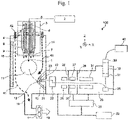
- FIG. 1 is a cross-sectional view showing a configuration of a mass spectrometer 100 according to a first embodiment of the invention.
- the mass spectrometer 100 is a device that analyzes components of a sample by ions ionized by an ion source 3. A pressure of tens of megapascals or less is applied to a sample solution 1, in which the sample (object to be analyzed) is dissolved in a solvent such as methanol or water, by a syringe pump 2, and a liquid is supplied to a capillary 4 in the ion source 3 to which a high voltage is applied via a peak tube 5.
- a tip end of the capillary 4 is an ultrafine tube having an inner diameter of tens to hundreds of micrometers.
- the sample solution 1 is injected from the tip end of the capillary 4.
- a positive or negative voltage of kilovolts is applied to the capillary 4.
- a nebulizer gas pipe 6 having a concentric shaft is provided on an outer periphery of the capillary 4.
- a nebulizer gas (atomized gas) 7 flows in the nebulizer gas pipe 6 at a speed of liters/minute. Miniaturized droplets charged to the same sign as the voltage applied to the capillary 4 are generated downstream of the capillary 4.
- An auxiliary heating gas pipe 8 having a concentric shaft is further provided on an outer periphery of the nebulizer gas pipe 6.
- the auxiliary heating gas pipe 8 is heated by a heater having a capacity of hundreds of watts (not shown), and an auxiliary heating gas 9 such as a nitrogen gas is injected at a flow rate of tens of liters/minute.
- an auxiliary heating gas 9 such as a nitrogen gas is injected at a flow rate of tens of liters/minute.
- the ions 10 are taken in by an electric field of a counter plate 12 in which a hole having a diameter of millimeters is opened in a triangular pyramid shape.
- Neutral particles other than the ions 10 and the sample in a liquid state that is not vaporized are also taken in from the counter plate 12 to a downstream side by a flow generated by a vacuum difference. Since the neutral particles other than the ions, the sample solution 1 in the liquid state that is not vaporized, and the like cause contamination, a counter gas 13 flows back to an ion source 3 side at a flow rate of liters/minute so as to prevent the neutral particles and the sample solution from entering the inside of the counter plate 12 as much as possible.
- the sample solution 1 and the like that is not taken into the counter plate 12 passes through an exhaust pipe 18 by an air flow of a blower 17 and is discharged (19).
- a flow rate of the nebulizer gas 7 is about 3 liters/minute
- a flow rate of the auxiliary heating gas 9 is about 10 liters/minute
- a flow rate of the counter gas 13 is about 5 liters/minute
- a flow rate of a gas flowing downstream from the counter plate 12 is about 5 liters/minute, so that a difference of about 13 liters/minute is discharged from the blower 17.
- About 30% of a gas flow rate including the sample solution 1 flows toward the blower 17.
- the blower 17 may have a constant performance (air volume-pressure loss value) in a rotation speed, a supply voltage, and a frequency, or may have an exhaust performance that is changeable by changing the rotation speed.
- the ion source container 15, the exhaust pipe 18, and the blower 17 to which the sample is adhered are also desired to be heated to a high temperature of about 200°C so that the sample is not adhered.
- problems such as a large required heater capacity and an increased size of the device by adopting a complicated structure due to a heat insulating structure occur, and it is practically difficult to implement the process. Therefore, in practice, the sample solution 1 is adhered to the ion source container 15, the exhaust pipe 18, the blower 17, and the like. After the sample solution 1 is adhered, the sample solution 1 is separated and floated. When a component of the sample is detected, this detection becomes a cause of erroneous detection in which a component that is not supposed to be detected is detected.
- the ion source 3 includes the capillary 4, the nebulizer gas pipe 6, the auxiliary heating gas pipe 8, a heater (not shown), a high-voltage applying structure, an electric insulator, a gas introducing structure, a stage (not shown) that adjusts a position of the capillary or the like in X, Y, and Z axis directions shown in FIG. 1 by millimeters, and the like. By this stage, the position of the capillary 4 is adjusted so as to optimize a performance such as device sensitivity.
- the nitrogen gas (first gas) whose flow rate and pressure are controlled is supplied from a gas control unit (not shown) to the nebulizer gas pipe 6 and the auxiliary heating gas pipe 8.
- the ion source 3 is fixed to the ion source container 15 by fixing a stage portion with a screw.
- the ion source container 15 is made of metal such as aluminum or stainless steel.
- a monitoring window 16 made of transparent glass, resin, or the like is arranged on a side surface of the ion source container 15.
- the capillary 4 which is a consumable item, is replaced, the peak tube 5 is removed, only the capillary 4 is replaced, or the capillary 4 is taken out together with the nebulizer gas pipe 6 and replaced with a new one.
- the first pore 21 having a hole diameter of less than 1 millimeter and a length of tens of millimeters is provided downstream of the counter plate 12. Due to a large flow path resistance of a hole portion, an inflow amount to the first pore 21 is limited.
- the axis shifting unit 22 is provided downstream of the first pore 21. Since the component of the sample solution 1 in a liquid state or the like travels straight, the component collides with an inner wall of the axis shifting unit 22 and is removed. On the other hand, ions and light mass components flow downstream along the flow.
- the ion guide 25 of octopole and quadrupole that focuses ions are arranged downstream of the axis shifting unit 22.
- a high-frequency potential of positive and negative are applied to a Q rod (a round bar of metal or ceramics) adjacent to the ion guide 25, and the ions 10 are captured in a region surrounded by the Q rod.
- An axis of an octupole portion and an axis of a quadrupole portion are offset from each other by millimeters in a direction orthogonal to an ion traveling axis. As a result, the neutral particles and the like are removed, and only necessary ion components are moved downstream by an electric field in an ion traveling axis direction.
- a second pore 26 having a flat plate shape that has a hole having a diameter of millimeters and a plate thickness of millimeters is provided downstream of the ion guide 25.
- a plate having a pore By arranging a plate having a pore, a room having different vacuum degrees is formed, unnecessary ions are blocked by a pore portion, and only necessary components are taken out.
- the first pore 21, the axis shifting unit 22, the ion guide 25, and the second pore 26 are arranged in a first differential exhaust chamber 23.
- the first differential exhaust chamber 23 is evacuated by a dry pump 32 and kept at a vacuum degree of about hundreds of pascals.
- a quadrupole called an ion thermalizer 27 (collision damper) is provided downstream of the second pore 26.
- a high-frequency potential of positive and negative is applied to an adjacent Q rod, and the ions 10 are captured in a region surrounded by the Q rod.
- Kinetic energy of the ions 10 is reduced due to collision with a residual gas, and the ions are focused in the vicinity of the ion traveling axis.
- a third pore 28 having a flat plate shape that has a hole having a diameter of millimeters and a plate thickness of millimeters is provided downstream of the ion thermalizer 27.
- the second pore 26, the ion thermalizer 27, and the third pore 28 are arranged in a second differential exhaust chamber 30.
- the second differential exhaust chamber 30 is connected to a first exhaust port of a turbo molecular pump 29, and is maintained at a vacuum degree of pascals.
- a triple quadrupole (mass filter) 31 IS provided downstream of the third pore 28.
- An ion detector including the triple quadrupole 31, a conversion dynode 36, a scintillator 37, an electron multiplier 38, and the like is arranged in an analysis chamber 33.
- the analysis chamber 33 is evacuated from a second exhaust port of the turbo molecular pump 29 and is maintained at a vacuum degree of 1E -3 pascals or less.
- a downstream side of the turbo molecular pump 29 is connected to the dry pump 32 to exhaust gas therefrom.
- the triple quadrupole 31 includes a first quadrupole, a collision chamber, and a second quadrupole from an upstream side.
- the first quadrupole allows only precursor ions of a particular mass-to-charge ratio (m/z) to pass by controlling a high-frequency voltage applied thereto.
- the ions 10 are guided to the collision chamber into which a collision gas (helium, nitrogen gas, or the like) located downstream of the ions 10 was introduced.
- the ions 10 collide with the gas, and are cleaved at sites where chemical bonds are weak.
- the cleaved ions 10 are referred to as product ions.
- the ions 10 are incident on the second quadrupole located downstream of the ions 10 and subjected to mass separation, and thereby the quantitative analysis can be performed with high sensitivity.
- the ions 10 are incident on the conversion dynode 36 by an electric field. Secondary electrons are generated by an ion collision, attracted by the electric field, and incident on the scintillator 37. Photoelectrons are generated, amplified by the electron multiplier 38, and converted by an analog/digital converter 39. A mass spectrum based on a digital value is displayed on a monitor 40. A sample component is specified by being compared with known data collected in advance. With these configurations, the first differential exhaust chamber 23 in FIG. 1 and each configuration portion arranged downstream of the first differential exhaust chamber 23 function as an ion measuring unit.
- a gas 42 flows from an upstream side of the ion generation region 11.
- the gas 42 flows from a hole portion or the like provided in the ion source container 15.
- a part of a spacer is inserted into an attachment surface between a fixed flange of the ion source 3 and the ion source container 15, and the gas 42 flows from a gap between the fixed flange and the ion source container 15.
- a reason why the nitrogen gas is desirable is that an organic solvent such as methanol may explode in a certain oxygen concentration region and cause ignition, and the nitrogen gas is to prevent the situation.
- a through hole may be provided in a part of the ion source 3 to flow the gas 42 into the inside of the ion source container 15.
- An inflow amount of the gas 42 is determined by (a) an area of the hole portion, an area of the gap, a flow path resistance of the flow, a flow path resistance value at each portion determined by a structure or the like inside the ion source container 15, (b) the flow rate flowing downstream from the first pore 21, (c) the flow rate of the nebulizer gas 7, (d) the flow rate of the auxiliary heating gas 9, (e) the flow rate of the sample solution 1, and (f) a discharge capacity determined by the rotation speed of the blower 17.
- the area of the hole portion, the area of the gap, a shape of the ion source container 15, and the structure inside the ion source container 15 have almost fixed values once the device is manufactured.
- the flow rate flowing downstream from the first pores 21 is a product of a pressure difference between the upstream side (atmosphere) and the downstream side of the first pore 21 and a conductance value determined by a shape of an elongated hole.
- the flow rate of the nebulizer gas 7 and the flow rate of the auxiliary heating gas 9 are determined.
- the gas 42 flows from an outer peripheral side (an inner wall surface side of the ion source container 15) of the ion generation region 11, and flows as a curtain gas 41 flowing toward the exhaust pipe 18 along an inner wall surface of the ion source container 15.
- the curtain gas 41 flows mainly to an outer side of the ion generation region 11.
- a reason for flowing to the outer side is that the ion generation region 11 contains a large amount of the ions 10 and the sample solution 1, and thus there is a high possibility that the flow in this region is disturbed and the device sensitivity is reduced.
- Another reason is that a gas flow toward the inner wall of the ion source container 15 is generated, the amount of the sample adhered to the inner wall of the ion source container 15 is increased, and the problems already described occur.
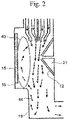
- FIG. 2 is a schematic diagram showing a result of simulating the flow inside an ion source of the related art.
- a broken line arrow in the drawing indicates a direction of a gas flow 44.
- a length of the arrow and a flow velocity are not proportional to each other.
- Calculation conditions are such that the flow rate of the nebulizer gas 7 is 2 liters/minute, the flow rate of the auxiliary heating gas 9 is 10 liters/minute, and the flow rate of the counter gas 13 is 5 liters/minute.
- the flow rate flowing out from the first pore 21 is about 5 liters/minute.
- a discharge amount of the blower 17 is about 12 liters/minute.
- a flow velocity at an outlet of the nebulizer gas pipe 6 exceeds a sound velocity at about 380 meters/second.
- a flow velocity at an outlet of the auxiliary heating gas pipe 8 is about 4 meters/second, and there is a large difference of about 100 times.
- a distance from the nebulizer gas pipes 6 to the ion source container 15 is tens of millimeters. Assuming that the flow velocity at the outlet of the nebulizer gas pipe 6 is maintained as it is and proceeds, the gas reaches the inner wall of the ion source container 15 at less than 1 millisecond. A part of the ions are taken into the inside of the counter plate 12 by the electric field within a short time.
- the gas containing the sample solution 1 collides with a lower portion of the exhaust pipe 18 to generate a reverse flow and form a circulation flow (vortex) 43.
- the gas containing the sample solution 1 collides with the ion source container 15 and the monitoring window 16 at a temperature lower than about 200°C, and part of the gas adheres to the ion source container 15 and the monitoring window 16.
- a part of the sample solution 1 is continuously supplied to the circulation flow (vortex) 43, and the sample is adhered to the inner surface of the ion source container 15 for a long time.
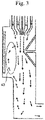
- FIG. 3 shows a result of simulating the flow in the ion source container 15 when a length of the exhaust pipe 18 is increased in order to reduce the reverse flow as compared with FIG. 2 .
- the flow velocity of the gas containing the sample at the lower portion of the exhaust pipe 18 is reduced, and the reverse flow is less likely to occur.
- the length of the exhaust pipe 18 is limited.
- a reverse flow region is reduced, but the circulation flow (vortex) 43 is present. Therefore, as in FIG. 2 , the sample is adhered to the ion source container 15. Although an adhesion amount can be reduced, the above problems are still generated.
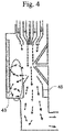
- FIG. 4 shows a result of simulating the flow in the ion source container 15 when the centralized exhaust pipe 45 is added to the structure of FIG. 2 .
- the centralized exhaust pipe 45 makes it possible to reduce the reverse flow generated by the gas colliding with the lower portion of the exhaust pipe 18.
- a part of the gas containing the sample solution 1 collides with the centralized exhaust pipe 45, and the circulation flow (vortex) 43 shown in the figure is generated.
- two circulation flows (vortex) 43 shown in the figure are generated.
- a part of the sample solution 1 is continuously supplied to the circulation flow (vortex) 43, and the sample is adhered to the inner surface of the ion source container 15 for a long time.
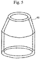
- FIG. 5 is a schematic diagram of the centralized exhaust pipe 45.
- the centralized exhaust pipe 45 is a metal pipe having an outermost diameter of about 30 millimeters and a height of about 60 millimeters, and a diameter of a tip end portion thereof is tapered.
- the centralized exhaust pipe 45 is arranged in the vicinity of the counter plate 12.
- the centralized exhaust pipe 45 is kept at a high temperature by heat-insulating and heating with the heater.
- FIG. 6 is a diagram showing a state of the flow inside the ion source container 15 according to the first embodiment.
- the gas 42 flows in at a flow rate of 20 liters/minute. Other calculation conditions are the same as those in FIG. 2 .
- Apart of the gas 42 is a flow of the curtain gas 41 along the inner wall of the ion source container 15.
- the curtain gas 41 acts to push the circulation flow (vortex) 43 shown in FIG. 2 to the downstream side. Accordingly, it is possible to reduce the amount of the sample adhered to the inner wall surface of the ion source container 15, and it is possible to solve the problems caused by the adhesion.
- FIG. 7 is a diagram showing a state of the flow inside the ion source container 15 when the centralized exhaust pipe 45 is added to the structure of FIG. 6 .
- the flow rate of the gas 42 is 20 liters/minute as in FIG. 6 .
- the other calculation conditions are the same as those in FIG. 2 .
- An intake port of the centralized exhaust pipe 45 is arranged at a position where a central axis of the ion source 3 is extended.
- the branched circulation flow (vortex) 43 shown in FIG. 4 is small.
- the flow does not reach the inner wall of the ion source container 15. As a result, it is possible to solve the problems caused by the sample adhesion.
- FIG. 8 is a diagram showing a structure of a gas supply member 48.
- the gas supply member 48 is a member that uniformly irradiates the gas 42, and is arranged at an inlet portion through which the gas 42 flows into the ion source container 15.
- the gas 42 is supplied into the ion source container 15 from a gas source 52 such as a nitrogen gas cylinder to an inlet hole 47 of the gas supply member 48 via a mass flow controller 51 (gas supply device) at a required pressure and flow rate.
- the gas 42 spreads inside the gas supply member 48.
- a large number of outlet holes 49 having a smaller diameter than the inlet hole 47 are provided on a lower surface of the gas supply member 48.
- the number of outlet holes 49 is larger than that of the inlet hole 47.
- a gas flow velocity corresponds to a current flow value I
- a difference between a gas pressure supplied from the mass flow controller 51 and a pressure inside the ion source container 15 corresponds to a potential difference V.
- R1 is a flow path resistance value in the inlet hole 47
- the flow path resistance value of R3m is increased (conductance is reduced).
- V31 gas outlet flow velocity in each section
- V32 ⁇ ... ⁇ V3m ⁇ V1 (inlet flow velocity)
- an outflow velocity at each gas outlet of the gas supply member 48 can be made uniform. That is, the gas 42 can be radiated in a shower shape.
- a reason why the gas is uniformly radiated in the shower shape is to form a flow of the curtain gas 41 with less turbulence inside the ion source container 15.
- a laminar flow is formed.
- the curtain gas 41 is preferably the laminar flow with less turbulence.
- the gas source 52, the mass flow controller 51, the gas supply member 48, and the inlet hole to which the gas supply member 48 is attached function as a gas supply unit (second gas supply unit) that supplies the gas 42 to the inside of the ion source container 15.
- Discharge ports (outlet holes 49) of the gas 42 are arranged on the upstream side of the ion generation region 11 and on the outer side of the central axis of the ion source 3 (a side closer to the inner wall of the ion source container 15) in a direction along the gas flow.
- the inlet hole, the gas source, and the like that supply the nebulizer gas 7 and the like function as a gas supply unit (first gas supply unit) that supplies these gases to the ion source 3.
- the mass spectrometer 100 flows the gas 42 toward the exhaust pipe 18 along the inner wall of the ion source container 15. As a result, the circulation flow 43 of the sample solution 1 can be prevented, and the sample can be smoothly discharged. As a result, the sample solution 1 is prevented from adhering to the inner wall of the ion source container 15 or the like, and staying time of a residual sample inside the ion source container 15 can be shortened. Therefore, when the same sample is continuously analyzed, since the residual time and amount of the sample are reduced, accuracy of the quantitative analysis is improved, and the S/N ratio is improved.
- the mass spectrometer 100 of the first embodiment even when different samples are analyzed, an influence of the previous sample can be reduced, and a risk of the erroneous detection and an erroneous determination can be reduced. Further, it is possible to minimize the adhesion amount of dirt to the downstream ion lens and to extend the maintenance cycle. As a result, a processing throughput of the apparatus can be improved, and the maintenance cost in a certain period of time (for example, per year) can be reduced.
- the gas supply member 48 can make the flow velocity of the curtain gas 41 slower than that of other gases such as the nebulizer gas 7.
- the flow velocity of the curtain gas 41 may be similarly reduced by adjusting the flow velocity of the gas 42 by the mass flow controller 51, which will be described later.
- FIG. 9 is a configuration diagram of the mass spectrometer 100 according to a second embodiment of the invention.
- the ion source container 15 has a cylindrical shape having an axis in an axial direction of the counter plates ⁇ 12. A flat portion is provided in the cylindrical shape, and the ion source 3 is mounted on a flat surface thereof.
- a guide plate 55 is further provided in addition to the configuration described in the first embodiment.
- the guide plate 55 is curved along an inner circumference of a cylinder of the ion source container 15, thereby guiding the curtain gas 41 along the inner wall of the ion source container 15.
- the guide plate 55 includes the flat portion for fixing and has an R surface along the inner wall of the ion source container 15.
- the flat portion of the guide plate 55 is fixed to the ion source container 15 by, for example, a screw. Other configurations are the same as those of the first embodiment.
- the curtain gas 41 can flow along the inner wall of the ion source container 15 by the guide plate 55. As a result, since the curtain gas 41 reliably avoids the ion generation region 11, it is possible to prevent an ion generation action in the ion generation region 11 from being inhibited.
- a flow rate of the sample solution 1, a temperature of the ion source 3, a flow rate of the nebulizer gas 7, a flow rate of the auxiliary heating gas 9, a flow rate of the counter gas 13, and the like, which are analysis conditions, are different depending on an analysis object. Therefore, a gas flow in the ion source container 15 differs for each analysis object. Depending on the conditions, it is expected that the circulation flow (vortex) 43 is generated and a problem caused by the generation is generated. Therefore, in a third embodiment of the invention, an operation procedure for checking whether the curtain gas 41 sufficiently acts will be described.
- the configuration of the mass spectrometer 100 is the same as that of the first and second embodiments.
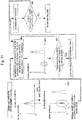
- FIG. 10 is a flowchart showing a procedure for checking the action of the curtain gas 41. Hereinafter, each procedure will be described with reference to FIG. 10 .
- a sample A is analyzed using the mass spectrometer 100 (step 1). As an analysis result, a detection signal distribution corresponding to the sample A is obtained.
- a sample B is analyzed (step 2).
- a residual component of the sample A exceeding a threshold value (determination value) is detected. It is considered that this residual component is generated by the circulation flow (vortex) 43 inside the ion source container 15.
- the mass flow controller 51 increases or decreases the inflow amount of the gas 42, or increases or decreases the rotation speed of the blower 17 when an inlet of the gas 42 is open to the atmosphere (step 3). Both of these operations may be performed. As a result, the flow rate of the curtain gas 41 inside the ion source container 15 is changed. Thereafter, a residual amount of the sample A is checked again. An operation of changing the flow rate of the curtain gas 41 is repeated until the residual amount of the sample A is equal to or less than the threshold value (determination value) (step 4).
- step 5 rechecking is performed under the same conditions (step 5).
- the processing returns to step 3 and the same procedure is repeated.
- the residual amount of the sample A is not equal to or less than the threshold value even when the rechecking is repeated a predetermined number of times, it is considered that the device is abnormal or the inside of the ion source container 15 is already contaminated, and thus an alarm is issued and the mass spectrometer 100 is stopped.
- the curtain gas 41 can reliably act, and a highly accurate analysis can be performed in which an influence of carryover and cross-contamination is prevented.
- the outlet holes 49 of the gas supply member 48 are not necessarily arranged at equal intervals.
- the number of outlet holes 49 may be increased at a position at which a larger amount of curtain gas 41 is desired to flow.
- the number of outlet holes 49 may be increased at a position at which the flow velocity of the curtain gas 41 is desired to be reduced.
- the ion source 3 using an electrospray ionization method as the ionization method has been described.
- the ion source 3 using an atmospheric pressure chemical ionization method, a chemical ionization method (CI method), an electron impact ionization method (EI method), or the like may be used.
- An ECR (microwave) plasma ion source, an inductively coupled plasma ion source, a penning ion source, a laser ion source, or the like may be used as the ion source 3.
- a quadrupole mass spectrometer has been exemplified as the mass spectrometer 100.
- a time of flight mass spectrometer TOF/MS
- a fourier transform ion cyclotron resonance mass spectrometer and a magnetic sector mass spectrometer may be used.
Landscapes
- Chemical & Material Sciences (AREA)
- Analytical Chemistry (AREA)
- Physics & Mathematics (AREA)
- Engineering & Computer Science (AREA)
- Plasma & Fusion (AREA)
- Other Investigation Or Analysis Of Materials By Electrical Means (AREA)
Abstract
Description
- The present invention relates to a mass spectrometer using an ion source.
- Ionization by an electrospray ionization (ESI) method is performed in the following procedure. A sample solution flows through a capillary to which a high voltage is applied, a sample is ejected from a tip end of the capillary, heated gas is blown from a periphery, and the sample solution is sprayed to generate charged droplets. When the charged droplets are evaporated and split, ions are generated.
- In a mass spectrometer using ions generated from an ion source, the ions are drawn in a low vacuum vacuumed by a vacuum pump by an electric field or the like. The ions pass through an ion lens having various functions, and are then guided to a quadrupole analysis unit. The quadrupole analysis unit includes four metal rods. A high frequency voltage and a DC voltage are applied to these metal rods, and specific ions are separated by passing only those having a ratio m/z of a mass (m) and an electric charge (z) of the specific ions.
- Components are analyzed by detecting the separated ions with an ion detector. A quadrupole analysis unit including triple stations is called a triple quadrupole analysis unit. In this configuration, mass separation is performed in a first stage and a third stage, and collision induced dissociation (CID) is performed in a second stage.
- A technique described in the following
PTL 1 provides a second gas source that supplies a second gas to an ionization region (a region between an ion source and a collection conduit) at a predetermined flow rate. The second gas is supplied from a direction perpendicular to a direction in which the ion source emits a gas. - In the following
PTL 2, an ESI ion source and an atmospheric pressure chemical ionization (APCI) ion source are arranged in the same ion source container, a distance between an ionization probe outlet end and a heating chamber is changed by a driving device, and two ionization methods are individually performed to quickly change an ESI mode and an APCI mode, so that a throughput of an apparatus is increased. -
- PTL 1:
JP-A-2007-066903 - PTL 2:
Japanese Patent No. 6181764 - When the sample solution is not smoothly discharged from the inside of the ion source and remains for a long time and a sample to be analyzed next is of the same type, a previous remaining component amount is overlapped in an analysis result, and a detected signal amount is increased. That is, accuracy of a quantitative analysis is reduced. In addition, since a background component that is noise remains, a signal (S)/noise (N) ratio changes. When a sample to be analyzed next is different from the previous sample and the previous sample remains, a signal of a sample that is not supposed to be present is detected. That is, a result of an erroneous detection is obtained.
- When the sample is not immediately discharged from the inside of the ion source and remains for a long time, an amount of the sample inside the ion source is increased, and the amount of the sample flowing into the ion lens on a downstream side is increased. As a result, an amount of the sample adhered to an ion source wall surface or the ion lens is increased, and a maintenance cycle for removing the sample is shortened. As a result, problems such as a decrease in a processing throughput of the apparatus and an increase in maintenance cost occur.
- In
PTLs - In the mass spectrometer according to the invention, in addition to a first gas used for ionizing an ion source, a second gas flowing toward an exhaust unit along an inner wall of the ion source container is supplied inside the ion source container.
- According to the mass spectrometer of the invention, a flow of the second gas (flow of a curtain gas) along a wall surface of the ion source container is generated, and a circulation flow such as a vortex can be prevented from being generated inside the ion source. As a result, an amount of the sample adhered to the wall surface or the like can be reduced.
-
- [
FIG. 1] FIG. 1 is a cross-sectional view showing a configuration of amass spectrometer 100 according to a first embodiment. - [
FIG. 2] FIG. 2 is a schematic diagram showing a result of simulating a flow inside an ion source of the related art. - [
FIG. 3] FIG. 3 shows a result of simulating a flow in anion source container 15 when a length of anexhaust pipe 18 is increased in order to reduce a reverse flow as compared withFIG. 2 . - [
FIG. 4] FIG. 4 shows a result of simulating the flow in theion source container 15 when a centralizedexhaust pipe 45 is added to a structure ofFIG. 2 . - [
FIG. 5] FIG. 5 is a schematic diagram of the centralizedexhaust pipe 45. - [
FIG. 6] FIG. 6 is a diagram showing a state of the flow inside theion source container 15 according to the first embodiment. - [
FIG. 7] FIG. 7 is a diagram showing a state of the flow inside theion source container 15 when the centralizedexhaust pipe 45 is added to a structure ofFIG. 6 . - [
FIG. 8] FIG. 8 is a diagram showing a structure of agas supply member 48. - [
FIG. 9] FIG. 9 is a configuration diagram of amass spectrometer 100 according to a second embodiment. - [
FIG. 10] FIG. 10 is a flowchart showing a procedure for checking an action of acurtain gas 41. -
FIG. 1 is a cross-sectional view showing a configuration of amass spectrometer 100 according to a first embodiment of the invention. Themass spectrometer 100 is a device that analyzes components of a sample by ions ionized by anion source 3. A pressure of tens of megapascals or less is applied to asample solution 1, in which the sample (object to be analyzed) is dissolved in a solvent such as methanol or water, by asyringe pump 2, and a liquid is supplied to acapillary 4 in theion source 3 to which a high voltage is applied via apeak tube 5. A tip end of thecapillary 4 is an ultrafine tube having an inner diameter of tens to hundreds of micrometers. - The
sample solution 1 is injected from the tip end of thecapillary 4. A positive or negative voltage of kilovolts is applied to thecapillary 4. Anebulizer gas pipe 6 having a concentric shaft is provided on an outer periphery of thecapillary 4. A nebulizer gas (atomized gas) 7 flows in thenebulizer gas pipe 6 at a speed of liters/minute. Miniaturized droplets charged to the same sign as the voltage applied to thecapillary 4 are generated downstream of thecapillary 4. An auxiliaryheating gas pipe 8 having a concentric shaft is further provided on an outer periphery of thenebulizer gas pipe 6. The auxiliaryheating gas pipe 8 is heated by a heater having a capacity of hundreds of watts (not shown), and anauxiliary heating gas 9 such as a nitrogen gas is injected at a flow rate of tens of liters/minute. As a result, vaporization and miniaturization of the droplets are further accelerated. When a surface electric field increase of the miniaturized droplets is increased and a repulsive force between electric charges exceeds a surface tension of the liquid, the droplets are split. Next, ion evaporation occurs, andions 10 are generated in anion generation region 11. Theion generation region 11 is formed in a downstream region where thesample solution 1 is ejected. - The
ions 10 are taken in by an electric field of acounter plate 12 in which a hole having a diameter of millimeters is opened in a triangular pyramid shape. Neutral particles other than theions 10 and the sample in a liquid state that is not vaporized are also taken in from thecounter plate 12 to a downstream side by a flow generated by a vacuum difference. Since the neutral particles other than the ions, thesample solution 1 in the liquid state that is not vaporized, and the like cause contamination, acounter gas 13 flows back to anion source 3 side at a flow rate of liters/minute so as to prevent the neutral particles and the sample solution from entering the inside of thecounter plate 12 as much as possible. - Surfaces of the
counter plate 12, afirst pore 21, and an axis shifting unit 22 are heated to about 200°C by a heater (not shown) in order to reduce the contamination due to sample adhesion as much as possible. In some cases, subsequent ion lenses (for example, ion guide 25) are also heated. - The
sample solution 1 and the like that is not taken into thecounter plate 12 passes through anexhaust pipe 18 by an air flow of ablower 17 and is discharged (19). A flow rate of thenebulizer gas 7 is about 3 liters/minute, a flow rate of theauxiliary heating gas 9 is about 10 liters/minute, a flow rate of thecounter gas 13 is about 5 liters/minute, and a flow rate of a gas flowing downstream from thecounter plate 12 is about 5 liters/minute, so that a difference of about 13 liters/minute is discharged from theblower 17. About 30% of a gas flow rate including thesample solution 1 flows toward theblower 17. - The
blower 17 may have a constant performance (air volume-pressure loss value) in a rotation speed, a supply voltage, and a frequency, or may have an exhaust performance that is changeable by changing the rotation speed. - Originally, the
ion source container 15, theexhaust pipe 18, and theblower 17 to which the sample is adhered are also desired to be heated to a high temperature of about 200°C so that the sample is not adhered. However, problems such as a large required heater capacity and an increased size of the device by adopting a complicated structure due to a heat insulating structure occur, and it is practically difficult to implement the process. Therefore, in practice, thesample solution 1 is adhered to theion source container 15, theexhaust pipe 18, theblower 17, and the like. After thesample solution 1 is adhered, thesample solution 1 is separated and floated. When a component of the sample is detected, this detection becomes a cause of erroneous detection in which a component that is not supposed to be detected is detected. In addition, even when a sample of the same type is analyzed, a next detection amount is increased from an originally correct amount, and measurement accuracy of a quantitative analysis is reduced. In addition, since an amount of the component flowing into the ion lens downstream of thecounter plate 12 is increased and a maintenance cycle is necessary to be shortened, problems such as an increase in maintenance cost and a decrease in a throughput of an apparatus occur. - The
ion source 3 includes thecapillary 4, thenebulizer gas pipe 6, the auxiliaryheating gas pipe 8, a heater (not shown), a high-voltage applying structure, an electric insulator, a gas introducing structure, a stage (not shown) that adjusts a position of the capillary or the like in X, Y, and Z axis directions shown inFIG. 1 by millimeters, and the like. By this stage, the position of thecapillary 4 is adjusted so as to optimize a performance such as device sensitivity. The nitrogen gas (first gas) whose flow rate and pressure are controlled is supplied from a gas control unit (not shown) to thenebulizer gas pipe 6 and the auxiliaryheating gas pipe 8. - The
ion source 3 is fixed to theion source container 15 by fixing a stage portion with a screw. Theion source container 15 is made of metal such as aluminum or stainless steel. In order to monitor a state or the like inside theion source container 15, amonitoring window 16 made of transparent glass, resin, or the like is arranged on a side surface of theion source container 15. - When the
capillary 4, which is a consumable item, is replaced, thepeak tube 5 is removed, only thecapillary 4 is replaced, or thecapillary 4 is taken out together with thenebulizer gas pipe 6 and replaced with a new one. - The
first pore 21 having a hole diameter of less than 1 millimeter and a length of tens of millimeters is provided downstream of thecounter plate 12. Due to a large flow path resistance of a hole portion, an inflow amount to thefirst pore 21 is limited. - The axis shifting unit 22 is provided downstream of the
first pore 21. Since the component of thesample solution 1 in a liquid state or the like travels straight, the component collides with an inner wall of the axis shifting unit 22 and is removed. On the other hand, ions and light mass components flow downstream along the flow. - The
ion guide 25 of octopole and quadrupole that focuses ions are arranged downstream of the axis shifting unit 22. A high-frequency potential of positive and negative are applied to a Q rod (a round bar of metal or ceramics) adjacent to theion guide 25, and theions 10 are captured in a region surrounded by the Q rod. An axis of an octupole portion and an axis of a quadrupole portion are offset from each other by millimeters in a direction orthogonal to an ion traveling axis. As a result, the neutral particles and the like are removed, and only necessary ion components are moved downstream by an electric field in an ion traveling axis direction. - A
second pore 26 having a flat plate shape that has a hole having a diameter of millimeters and a plate thickness of millimeters is provided downstream of theion guide 25. By arranging a plate having a pore, a room having different vacuum degrees is formed, unnecessary ions are blocked by a pore portion, and only necessary components are taken out. Thefirst pore 21, the axis shifting unit 22, theion guide 25, and thesecond pore 26 are arranged in a firstdifferential exhaust chamber 23. The firstdifferential exhaust chamber 23 is evacuated by adry pump 32 and kept at a vacuum degree of about hundreds of pascals. - A quadrupole called an ion thermalizer 27 (collision damper) is provided downstream of the
second pore 26. Similarly to theion guide 25, a high-frequency potential of positive and negative is applied to an adjacent Q rod, and theions 10 are captured in a region surrounded by the Q rod. Kinetic energy of theions 10 is reduced due to collision with a residual gas, and the ions are focused in the vicinity of the ion traveling axis. Athird pore 28 having a flat plate shape that has a hole having a diameter of millimeters and a plate thickness of millimeters is provided downstream of theion thermalizer 27. Thesecond pore 26, theion thermalizer 27, and thethird pore 28 are arranged in a seconddifferential exhaust chamber 30. The seconddifferential exhaust chamber 30 is connected to a first exhaust port of a turbomolecular pump 29, and is maintained at a vacuum degree of pascals. - A triple quadrupole (mass filter) 31 IS provided downstream of the
third pore 28. An ion detector including thetriple quadrupole 31, aconversion dynode 36, ascintillator 37, anelectron multiplier 38, and the like is arranged in ananalysis chamber 33. Theanalysis chamber 33 is evacuated from a second exhaust port of the turbomolecular pump 29 and is maintained at a vacuum degree of 1E-3 pascals or less. A downstream side of the turbomolecular pump 29 is connected to thedry pump 32 to exhaust gas therefrom. Thetriple quadrupole 31 includes a first quadrupole, a collision chamber, and a second quadrupole from an upstream side. The first quadrupole allows only precursor ions of a particular mass-to-charge ratio (m/z) to pass by controlling a high-frequency voltage applied thereto. Theions 10 are guided to the collision chamber into which a collision gas (helium, nitrogen gas, or the like) located downstream of theions 10 was introduced. Theions 10 collide with the gas, and are cleaved at sites where chemical bonds are weak. The cleavedions 10 are referred to as product ions. Theions 10 are incident on the second quadrupole located downstream of theions 10 and subjected to mass separation, and thereby the quantitative analysis can be performed with high sensitivity. - The
ions 10 are incident on theconversion dynode 36 by an electric field. Secondary electrons are generated by an ion collision, attracted by the electric field, and incident on thescintillator 37. Photoelectrons are generated, amplified by theelectron multiplier 38, and converted by an analog/digital converter 39. A mass spectrum based on a digital value is displayed on amonitor 40. A sample component is specified by being compared with known data collected in advance. With these configurations, the firstdifferential exhaust chamber 23 inFIG. 1 and each configuration portion arranged downstream of the firstdifferential exhaust chamber 23 function as an ion measuring unit. - A gas 42 (desirably, inert gas such as nitrogen) flows from an upstream side of the
ion generation region 11. Thegas 42 flows from a hole portion or the like provided in theion source container 15. Alternatively, a part of a spacer is inserted into an attachment surface between a fixed flange of theion source 3 and theion source container 15, and thegas 42 flows from a gap between the fixed flange and theion source container 15. A reason why the nitrogen gas is desirable is that an organic solvent such as methanol may explode in a certain oxygen concentration region and cause ignition, and the nitrogen gas is to prevent the situation. As a gas introduction position, a through hole may be provided in a part of theion source 3 to flow thegas 42 into the inside of theion source container 15. - An inflow amount of the
gas 42 is determined by (a) an area of the hole portion, an area of the gap, a flow path resistance of the flow, a flow path resistance value at each portion determined by a structure or the like inside theion source container 15, (b) the flow rate flowing downstream from thefirst pore 21, (c) the flow rate of thenebulizer gas 7, (d) the flow rate of theauxiliary heating gas 9, (e) the flow rate of thesample solution 1, and (f) a discharge capacity determined by the rotation speed of theblower 17. - The area of the hole portion, the area of the gap, a shape of the
ion source container 15, and the structure inside theion source container 15 have almost fixed values once the device is manufactured. The flow rate flowing downstream from the first pores 21 is a product of a pressure difference between the upstream side (atmosphere) and the downstream side of thefirst pore 21 and a conductance value determined by a shape of an elongated hole. In addition, when analysis conditions are determined, the flow rate of thenebulizer gas 7 and the flow rate of theauxiliary heating gas 9 are determined. In order to change a state of the flow of thegas 42 in theion source container 15, it is necessary to change the inflow amount of thegas 42. For this purpose, it is necessary to change the rotation speed of theblower 17. - The
gas 42 flows from an outer peripheral side (an inner wall surface side of the ion source container 15) of theion generation region 11, and flows as acurtain gas 41 flowing toward theexhaust pipe 18 along an inner wall surface of theion source container 15. Thecurtain gas 41 flows mainly to an outer side of theion generation region 11. A reason for flowing to the outer side is that theion generation region 11 contains a large amount of theions 10 and thesample solution 1, and thus there is a high possibility that the flow in this region is disturbed and the device sensitivity is reduced. Another reason is that a gas flow toward the inner wall of theion source container 15 is generated, the amount of the sample adhered to the inner wall of theion source container 15 is increased, and the problems already described occur. -
FIG. 2 is a schematic diagram showing a result of simulating the flow inside an ion source of the related art. A broken line arrow in the drawing indicates a direction of agas flow 44. A length of the arrow and a flow velocity are not proportional to each other. Calculation conditions are such that the flow rate of thenebulizer gas 7 is 2 liters/minute, the flow rate of theauxiliary heating gas 9 is 10 liters/minute, and the flow rate of thecounter gas 13 is 5 liters/minute. The flow rate flowing out from thefirst pore 21 is about 5 liters/minute. A discharge amount of theblower 17 is about 12 liters/minute. A flow velocity at an outlet of thenebulizer gas pipe 6 exceeds a sound velocity at about 380 meters/second. A flow velocity at an outlet of the auxiliaryheating gas pipe 8 is about 4 meters/second, and there is a large difference of about 100 times. A distance from thenebulizer gas pipes 6 to theion source container 15 is tens of millimeters. Assuming that the flow velocity at the outlet of thenebulizer gas pipe 6 is maintained as it is and proceeds, the gas reaches the inner wall of theion source container 15 at less than 1 millisecond. A part of the ions are taken into the inside of thecounter plate 12 by the electric field within a short time. - The gas containing the
sample solution 1 collides with a lower portion of theexhaust pipe 18 to generate a reverse flow and form a circulation flow (vortex) 43. The gas containing thesample solution 1 collides with theion source container 15 and themonitoring window 16 at a temperature lower than about 200°C, and part of the gas adheres to theion source container 15 and themonitoring window 16. A part of thesample solution 1 is continuously supplied to the circulation flow (vortex) 43, and the sample is adhered to the inner surface of theion source container 15 for a long time. -
FIG. 3 shows a result of simulating the flow in theion source container 15 when a length of theexhaust pipe 18 is increased in order to reduce the reverse flow as compared withFIG. 2 . By increasing the length of theexhaust pipe 18, the flow velocity of the gas containing the sample at the lower portion of theexhaust pipe 18 is reduced, and the reverse flow is less likely to occur. However, since the size of the device is limited, the length of theexhaust pipe 18 is limited. In a structure ofFIG. 3 , a reverse flow region is reduced, but the circulation flow (vortex) 43 is present. Therefore, as inFIG. 2 , the sample is adhered to theion source container 15. Although an adhesion amount can be reduced, the above problems are still generated. -
FIG. 4 shows a result of simulating the flow in theion source container 15 when thecentralized exhaust pipe 45 is added to the structure ofFIG. 2 . Thecentralized exhaust pipe 45 makes it possible to reduce the reverse flow generated by the gas colliding with the lower portion of theexhaust pipe 18. On the other hand, a part of the gas containing thesample solution 1 collides with thecentralized exhaust pipe 45, and the circulation flow (vortex) 43 shown in the figure is generated. In a calculation, two circulation flows (vortex) 43 shown in the figure are generated. As inFIG. 2 , a part of thesample solution 1 is continuously supplied to the circulation flow (vortex) 43, and the sample is adhered to the inner surface of theion source container 15 for a long time. -
FIG. 5 is a schematic diagram of thecentralized exhaust pipe 45. Thecentralized exhaust pipe 45 is a metal pipe having an outermost diameter of about 30 millimeters and a height of about 60 millimeters, and a diameter of a tip end portion thereof is tapered. Thecentralized exhaust pipe 45 is arranged in the vicinity of thecounter plate 12. When an analysis operation is performed usingvarious sample solutions 1, a part of thesample solutions 1 is adhered to thecentralized exhaust pipe 45. The adhesion is a reason of the erroneous detection. Therefore, thecentralized exhaust pipe 45 is kept at a high temperature by heat-insulating and heating with the heater. -
FIG. 6 is a diagram showing a state of the flow inside theion source container 15 according to the first embodiment. Thegas 42 flows in at a flow rate of 20 liters/minute. Other calculation conditions are the same as those inFIG. 2 . Apart of thegas 42 is a flow of thecurtain gas 41 along the inner wall of theion source container 15. Thecurtain gas 41 acts to push the circulation flow (vortex) 43 shown inFIG. 2 to the downstream side. Accordingly, it is possible to reduce the amount of the sample adhered to the inner wall surface of theion source container 15, and it is possible to solve the problems caused by the adhesion. -
FIG. 7 is a diagram showing a state of the flow inside theion source container 15 when thecentralized exhaust pipe 45 is added to the structure ofFIG. 6 . The flow rate of thegas 42 is 20 liters/minute as inFIG. 6 . The other calculation conditions are the same as those inFIG. 2 . An intake port of thecentralized exhaust pipe 45 is arranged at a position where a central axis of theion source 3 is extended. The branched circulation flow (vortex) 43 shown inFIG. 4 is small. In addition, the flow does not reach the inner wall of theion source container 15. As a result, it is possible to solve the problems caused by the sample adhesion. -
FIG. 8 is a diagram showing a structure of agas supply member 48. Thegas supply member 48 is a member that uniformly irradiates thegas 42, and is arranged at an inlet portion through which thegas 42 flows into theion source container 15. Thegas 42 is supplied into theion source container 15 from agas source 52 such as a nitrogen gas cylinder to aninlet hole 47 of thegas supply member 48 via a mass flow controller 51 (gas supply device) at a required pressure and flow rate. Thegas 42 spreads inside thegas supply member 48. A large number of outlet holes 49 having a smaller diameter than theinlet hole 47 are provided on a lower surface of thegas supply member 48. The number of outlet holes 49 is larger than that of theinlet hole 47. - When a flow path resistance of the
gas supply member 48 is replaced with an equivalent electric circuit, a lower right figure ofFIG. 8 is obtained. A gas flow velocity corresponds to a current flow value I, and a difference between a gas pressure supplied from themass flow controller 51 and a pressure inside theion source container 15 corresponds to a potential difference V. R1 is a flow path resistance value in theinlet hole 47, R2n (n = 1, 2 ... n) is a flow path resistance value in each section inside thegas supply member 48, and R3m (m = 1, 2 ... m) is a flow path resistance value in the outlet holes 49. By reducing a hole diameter of the outlet holes 49 or making the flow path elongated, the flow path resistance value of R3m is increased (conductance is reduced). By setting R1 and R2n <<R3m, V31 (gas outlet flow velocity in each section) ≈ V32 ≈ ... ≈ V3m << V1 (inlet flow velocity), and an outflow velocity at each gas outlet of thegas supply member 48 can be made uniform. That is, thegas 42 can be radiated in a shower shape. - A reason why the gas is uniformly radiated in the shower shape is to form a flow of the
curtain gas 41 with less turbulence inside theion source container 15. Preferably, a laminar flow is formed. When the flow is turbulent, the sample adhered to the inner wall of theion source container 15 is likely to be detached, and the problems already described are likely to occur. Therefore, it can be said that thecurtain gas 41 is preferably the laminar flow with less turbulence. - The
gas source 52, themass flow controller 51, thegas supply member 48, and the inlet hole to which thegas supply member 48 is attached function as a gas supply unit (second gas supply unit) that supplies thegas 42 to the inside of theion source container 15. Discharge ports (outlet holes 49) of thegas 42 are arranged on the upstream side of theion generation region 11 and on the outer side of the central axis of the ion source 3 (a side closer to the inner wall of the ion source container 15) in a direction along the gas flow. Similarly, the inlet hole, the gas source, and the like that supply thenebulizer gas 7 and the like function as a gas supply unit (first gas supply unit) that supplies these gases to theion source 3. - The
mass spectrometer 100 according to the first embodiment flows thegas 42 toward theexhaust pipe 18 along the inner wall of theion source container 15. As a result, thecirculation flow 43 of thesample solution 1 can be prevented, and the sample can be smoothly discharged. As a result, thesample solution 1 is prevented from adhering to the inner wall of theion source container 15 or the like, and staying time of a residual sample inside theion source container 15 can be shortened. Therefore, when the same sample is continuously analyzed, since the residual time and amount of the sample are reduced, accuracy of the quantitative analysis is improved, and the S/N ratio is improved. - According to the
mass spectrometer 100 of the first embodiment, even when different samples are analyzed, an influence of the previous sample can be reduced, and a risk of the erroneous detection and an erroneous determination can be reduced. Further, it is possible to minimize the adhesion amount of dirt to the downstream ion lens and to extend the maintenance cycle. As a result, a processing throughput of the apparatus can be improved, and the maintenance cost in a certain period of time (for example, per year) can be reduced. - In the first embodiment, the
gas supply member 48 can make the flow velocity of thecurtain gas 41 slower than that of other gases such as thenebulizer gas 7. In addition, the flow velocity of thecurtain gas 41 may be similarly reduced by adjusting the flow velocity of thegas 42 by themass flow controller 51, which will be described later. -
FIG. 9 is a configuration diagram of themass spectrometer 100 according to a second embodiment of the invention. Theion source container 15 has a cylindrical shape having an axis in an axial direction of the counter plates¥ 12. A flat portion is provided in the cylindrical shape, and theion source 3 is mounted on a flat surface thereof. In the second embodiment, aguide plate 55 is further provided in addition to the configuration described in the first embodiment. Theguide plate 55 is curved along an inner circumference of a cylinder of theion source container 15, thereby guiding thecurtain gas 41 along the inner wall of theion source container 15. Theguide plate 55 includes the flat portion for fixing and has an R surface along the inner wall of theion source container 15. The flat portion of theguide plate 55 is fixed to theion source container 15 by, for example, a screw. Other configurations are the same as those of the first embodiment. - According to the
mass spectrometer 100 of the second embodiment, thecurtain gas 41 can flow along the inner wall of theion source container 15 by theguide plate 55. As a result, since thecurtain gas 41 reliably avoids theion generation region 11, it is possible to prevent an ion generation action in theion generation region 11 from being inhibited. - A flow rate of the
sample solution 1, a temperature of theion source 3, a flow rate of thenebulizer gas 7, a flow rate of theauxiliary heating gas 9, a flow rate of thecounter gas 13, and the like, which are analysis conditions, are different depending on an analysis object. Therefore, a gas flow in theion source container 15 differs for each analysis object. Depending on the conditions, it is expected that the circulation flow (vortex) 43 is generated and a problem caused by the generation is generated. Therefore, in a third embodiment of the invention, an operation procedure for checking whether thecurtain gas 41 sufficiently acts will be described. The configuration of themass spectrometer 100 is the same as that of the first and second embodiments. -
FIG. 10 is a flowchart showing a procedure for checking the action of thecurtain gas 41. Hereinafter, each procedure will be described with reference toFIG. 10 . - First, a sample A is analyzed using the mass spectrometer 100 (step 1). As an analysis result, a detection signal distribution corresponding to the sample A is obtained. Next, a sample B is analyzed (step 2). Here, it is assumed that a residual component of the sample A exceeding a threshold value (determination value) is detected. It is considered that this residual component is generated by the circulation flow (vortex) 43 inside the
ion source container 15. - The
mass flow controller 51 increases or decreases the inflow amount of thegas 42, or increases or decreases the rotation speed of theblower 17 when an inlet of thegas 42 is open to the atmosphere (step 3). Both of these operations may be performed. As a result, the flow rate of thecurtain gas 41 inside theion source container 15 is changed. Thereafter, a residual amount of the sample A is checked again. An operation of changing the flow rate of thecurtain gas 41 is repeated until the residual amount of the sample A is equal to or less than the threshold value (determination value) (step 4). - Since the sample A flows to the downstream side even when the sample A is left unattended, the detection amount is gradually reduced. Therefore, even when the residual amount of the sample A is equal to or less than the threshold value, the result may due to a worker taking time and effort in
step 3 andstep 4. Therefore, rechecking is performed under the same conditions (step 5). When the residual amount of the sample A is not equal to or less than the threshold value, the processing returns to step 3 and the same procedure is repeated. When the residual amount of the sample A is not equal to or less than the threshold value even when the rechecking is repeated a predetermined number of times, it is considered that the device is abnormal or the inside of theion source container 15 is already contaminated, and thus an alarm is issued and themass spectrometer 100 is stopped. - When the residual amount of the sample A is equal to or less than the threshold value, it is determined that generation of the circulation flow (vortex) 43 inside the
ion source container 15 is prevented, and the current analysis is performed (step 6). According to the above procedure, thecurtain gas 41 can reliably act, and a highly accurate analysis can be performed in which an influence of carryover and cross-contamination is prevented. - In the above embodiments, the outlet holes 49 of the
gas supply member 48 are not necessarily arranged at equal intervals. For example, the number of outlet holes 49 may be increased at a position at which a larger amount ofcurtain gas 41 is desired to flow. Similarly, the number of outlet holes 49 may be increased at a position at which the flow velocity of thecurtain gas 41 is desired to be reduced. - In the above embodiments, the
ion source 3 using an electrospray ionization method as the ionization method has been described. Alternatively, theion source 3 using an atmospheric pressure chemical ionization method, a chemical ionization method (CI method), an electron impact ionization method (EI method), or the like may be used. An ECR (microwave) plasma ion source, an inductively coupled plasma ion source, a penning ion source, a laser ion source, or the like may be used as theion source 3. - In the above embodiments, a quadrupole mass spectrometer has been exemplified as the
mass spectrometer 100. Alternatively, a time of flight mass spectrometer (TOF/MS), a fourier transform ion cyclotron resonance mass spectrometer, and a magnetic sector mass spectrometer may be used. -
- 1 sample solution
- 2 syringe pump
- 3 ion source
- 4 capillary
- 5 peak tube
- 6 nebulizer gas pipe
- 7 nebulizer gas
- 8 auxiliary heating gas pipe
- 9 auxiliary heating gas
- 10 ion
- 11 ion generation region
- 12 counter plate
- 13 counter gas
- 15 ion source container
- 16 monitoring window
- 17 blower
- 18 exhaust pipe
- 19 discharge
- 21 first pore
- 22 axis shifting unit
- 23 first differential exhaust chamber
- 24 dry pump
- 25 ion guide
- 26 second pore
- 27 ion thermalizer
- 28 third pore
- 29 turbo molecular pump
- 30 second differential exhaust chamber
- 31 triple quadrupole
- 32 dry pump
- 33 analysis chamber
- 36 conversion dynode
- 37 scintillator
- 38 electron multiplier
- 39 analog/digital converter
- 40 monitor
- 41 curtain gas
- 42 gas
- 43 circulation flow (vortex)
- 44 gas flow
- 45 centralized exhaust pipe
- 48 gas supply member
- 47 inlet hole
- 49 outlet hole
- 51 mass flow controller
- 52 gas source
- 55 guide plate
Claims (13)
- A mass spectrometer comprising:an ion source that generates ions;a container that accommodates the ion source;a first gas supply unit that supplies a first gas used by the ion source to generate the ions to the ion source;an exhaust unit that exhausts the first gas from the container; anda second gas supply unit that supplies a second gas that flows toward the exhaust unit along an inner wall of the container inside the container and outside the ion source.
- The mass spectrometer according to claim 1, whereina discharge port through which the second gas supply unit discharges the second gas is arranged on an upstream side of a discharge port through which the ion source discharges the first gas in a direction in which the first gas flows, andthe second gas supply unit supplies the second gas so as to flow from the upstream side toward the exhaust unit.
- The mass spectrometer according to claim 2, whereinthe second gas supply unit includes a member including an inlet hole for introducing the second gas and an outlet hole for discharging the second gas, andthe outlet hole is arranged on an outer side of an ejection port, from which the ion source ejects the first gas, when viewed from a center of the ion source on a plane perpendicular to a flow path through which the first gas passes through the inside of the ion source.
- The mass spectrometer according to claim 3, wherein
a flow path resistance generated by the outlet hole is larger than a flow path resistance generated by the inlet hole. - The mass spectrometer according to claim 4, wherein
the number of the outlet hole is larger than the number of the inlet hole. - The mass spectrometer according to claim 4, wherein
a hole diameter of the outlet hole is smaller than a hole diameter of the inlet hole. - The mass spectrometer according to claim 4, wherein
a flow path length of the outlet hole is larger than a flow path length of the inlet hole. - The mass spectrometer according to claim 1, further comprising:a gas supply device that supplies the second gas, whereinthe gas supply device supplies the second gas such that a flow velocity of the second gas is lower than a flow velocity of the first gas.
- The mass spectrometer according to claim 1, whereinthe exhaust unit includes an exhaust pipe that tapers from the exhaust unit toward the ion source, andan intake port of the exhaust pipe is arranged at a position where a central axis of the ion source is extended.
- The mass spectrometer according to claim 1, further comprising:
a guide plate that guides the second gas along the inner wall of the container. - The mass spectrometer according to claim 10, whereina side wall of the container has a curved shape, andthe guide plate is curved so as to guide the second gas along the curved shape.
- The mass spectrometer according to claim 1, further comprising:a measurement unit that measures an amount of a substance contained in a sample by using the ions; anda control unit that controls at least one of a flow rate of the second gas or an exhaust amount from the exhaust unit, whereinthe measurement unit measures a first sample containing a first substance, and then measures a second sample containing a second substance, andthe control unit performs at least one of increasing the flow rate of the second gas or increasing the exhaust amount from the exhaust unit when the first substance is detected to be equal to or more than a threshold value in a measurement result of the second sample by the measurement unit.
- The mass spectrometer according to claim 12, whereinthe control unit repeats the at least one of increasing the flow rate of the second gas or increasing the exhaust amount from the exhaust unit until an amount of the first substance detected by the measurement unit is less than the threshold value,when the amount of the first substance detected by the measurement unit is less than the threshold value, the measurement unit remeasures the first sample and then remeasures the second sample, andthe control unit performs the at least one of increasing the flow rate of the second gas or increasing the exhaust amount from the exhaust unit when the first substance is detected to be equal to or more than the threshold value in a measurement result of the second sample by the remeasurement.
Applications Claiming Priority (1)
| Application Number | Priority Date | Filing Date | Title |
|---|---|---|---|
| PCT/JP2019/027237 WO2021005730A1 (en) | 2019-07-10 | 2019-07-10 | Mass spectrometer |
Publications (2)
| Publication Number | Publication Date |
|---|---|
| EP3998624A1 true EP3998624A1 (en) | 2022-05-18 |
| EP3998624A4 EP3998624A4 (en) | 2023-03-29 |
Family
ID=74114994
Family Applications (1)
| Application Number | Title | Priority Date | Filing Date |
|---|---|---|---|
| EP19936872.1A Pending EP3998624A4 (en) | 2019-07-10 | 2019-07-10 | MASS SPECTROMETER |
Country Status (5)
| Country | Link |
|---|---|
| US (1) | US12087565B2 (en) |
| EP (1) | EP3998624A4 (en) |
| JP (1) | JP7138247B2 (en) |
| CN (1) | CN114026671B (en) |
| WO (1) | WO2021005730A1 (en) |
Families Citing this family (4)
| Publication number | Priority date | Publication date | Assignee | Title |
|---|---|---|---|---|
| JP7657089B2 (en) * | 2021-04-05 | 2025-04-04 | 株式会社日立ハイテク | Mass spectrometer and control method thereof |
| CN114496716A (en) * | 2022-01-24 | 2022-05-13 | 天津国科医工科技发展有限公司 | Atmospheric pressure ion source exhaust device of mass spectrometer |
| US20250087475A1 (en) * | 2022-02-28 | 2025-03-13 | Shimadzu Corporation | Mass spectrometer |
| WO2026052951A1 (en) * | 2024-09-05 | 2026-03-12 | Micromass Uk Limited | Analytical instrument |
Family Cites Families (14)
| Publication number | Priority date | Publication date | Assignee | Title |
|---|---|---|---|---|
| JP2001272375A (en) | 2000-03-24 | 2001-10-05 | Shimadzu Corp | Liquid chromatograph mass spectrometer |
| JP4164569B2 (en) * | 2002-06-25 | 2008-10-15 | 独立行政法人科学技術振興機構 | Jet discharge atmospheric pressure ionization method used for mass spectrometry etc. |
| DE102004025841B4 (en) * | 2004-05-24 | 2015-07-09 | Bruker Daltonik Gmbh | Method and apparatus for mass spectroscopic analysis of analytes |
| WO2006060130A2 (en) * | 2004-11-09 | 2006-06-08 | E.I. Dupont De Nemours And Company | Ion source for a mass spectrometer |
| US7397028B2 (en) | 2005-08-30 | 2008-07-08 | Agilent Technologies, Inc. | Apparatus and method for gas flow management |
| US7737395B2 (en) * | 2006-09-20 | 2010-06-15 | Agilent Technologies, Inc. | Apparatuses, methods and compositions for ionization of samples and mass calibrants |
| US8039795B2 (en) * | 2008-04-04 | 2011-10-18 | Agilent Technologies, Inc. | Ion sources for improved ionization |
| JP5718223B2 (en) * | 2008-05-30 | 2015-05-13 | パーキンエルマー ヘルス サイエンス インコーポレイテッドPerkinelmer Health Sciences Inc. | Simple and multi-operation mode ion sources used for atmospheric pressure chemical ionization |
| US8242441B2 (en) * | 2009-12-18 | 2012-08-14 | Thermo Finnigan Llc | Apparatus and methods for pneumatically-assisted electrospray emitter array |
| JP5497615B2 (en) * | 2010-11-08 | 2014-05-21 | 株式会社日立ハイテクノロジーズ | Mass spectrometer |
| CA2837478C (en) * | 2011-06-03 | 2019-02-26 | Perkinelmer Health Sciences, Inc. | Direct sample analysis ion source |
| US9852897B2 (en) * | 2012-11-29 | 2017-12-26 | Hitachi High-Technologies Corporation | Hybrid ion source, mass spectrometer, and ion mobility device |
| US9704699B2 (en) | 2013-09-05 | 2017-07-11 | Hitachi High-Technologies Corporation | Hybrid ion source and mass spectrometric device |
| GB201409604D0 (en) * | 2014-05-30 | 2014-07-16 | Shimadzu Corp | Improvements in or relating to mass spectrometry |
-
2019
- 2019-07-10 EP EP19936872.1A patent/EP3998624A4/en active Pending
- 2019-07-10 US US17/597,245 patent/US12087565B2/en active Active
- 2019-07-10 JP JP2021530412A patent/JP7138247B2/en active Active
- 2019-07-10 WO PCT/JP2019/027237 patent/WO2021005730A1/en not_active Ceased
- 2019-07-10 CN CN201980097858.5A patent/CN114026671B/en active Active
Also Published As
| Publication number | Publication date |
|---|---|
| CN114026671B (en) | 2024-12-13 |
| US20220319825A1 (en) | 2022-10-06 |
| JP7138247B2 (en) | 2022-09-15 |
| EP3998624A4 (en) | 2023-03-29 |
| WO2021005730A1 (en) | 2021-01-14 |
| JPWO2021005730A1 (en) | 2021-01-14 |
| US12087565B2 (en) | 2024-09-10 |
| CN114026671A (en) | 2022-02-08 |
Similar Documents
| Publication | Publication Date | Title |
|---|---|---|
| US12087565B2 (en) | Mass spectrometer | |
| US6177669B1 (en) | Vortex gas flow interface for electrospray mass spectrometry | |
| JP5671145B2 (en) | Atmospheric pressure ionization inlet of mass spectrometer | |
| JP2006510905A (en) | Method and apparatus for aerodynamic ion focusing | |
| EP3069375B1 (en) | Concentric apci surface ionization ion source, ion guide, and method of use | |
| CN205081089U (en) | Sample atomizer and sample analytic system | |
| EP2808888B1 (en) | Mass analysis device | |
| JP6685698B2 (en) | Method for generating sample atoms, method for analyzing a liquid sample and plasma source | |
| US8481927B2 (en) | High yield atmospheric pressure ion source for ion spectrometers in vacuum | |
| CN102574058B (en) | For the system of anti-backflow in ion gun | |
| JP6609379B2 (en) | Ion analyzer | |
| JP2000513873A (en) | Ion source for mass spectrometer and method of providing an ion source for analysis | |
| EP2981983B1 (en) | Improvements in and relating to the production and control of ions | |
| US20030062474A1 (en) | Electrospray ion source for mass spectrometry with atmospheric pressure desolvating capabilities | |
| JPH10247472A (en) | Surface ionization type ionizer | |
| US8680460B2 (en) | Converging-diverging supersonic shock disruptor for fluid nebulization and drop fragmentation | |
| CN111540665A (en) | Ionization device and application thereof | |
| US12002672B2 (en) | Apparatus and methods for reduced neutral contamination in a mass spectrometer | |
| US20240429037A1 (en) | Mass spectrometer for analyzing an analyte sample | |
| US8502162B2 (en) | Atmospheric pressure ionization apparatus and method |
Legal Events
| Date | Code | Title | Description |
|---|---|---|---|
| STAA | Information on the status of an ep patent application or granted ep patent |
Free format text: STATUS: THE INTERNATIONAL PUBLICATION HAS BEEN MADE |
|
| PUAI | Public reference made under article 153(3) epc to a published international application that has entered the european phase |
Free format text: ORIGINAL CODE: 0009012 |
|
| STAA | Information on the status of an ep patent application or granted ep patent |
Free format text: STATUS: REQUEST FOR EXAMINATION WAS MADE |
|
| 17P | Request for examination filed |
Effective date: 20220210 |
|
| AK | Designated contracting states |
Kind code of ref document: A1 Designated state(s): AL AT BE BG CH CY CZ DE DK EE ES FI FR GB GR HR HU IE IS IT LI LT LU LV MC MK MT NL NO PL PT RO RS SE SI SK SM TR |
|
| DAV | Request for validation of the european patent (deleted) | ||
| DAX | Request for extension of the european patent (deleted) | ||
| REG | Reference to a national code |
Ref country code: DE Ref legal event code: R079 Free format text: PREVIOUS MAIN CLASS: H01J0049100000 Ipc: H01J0049160000 |
|
| A4 | Supplementary search report drawn up and despatched |
Effective date: 20230227 |
|
| RIC1 | Information provided on ipc code assigned before grant |
Ipc: H01J 49/24 20060101ALI20230221BHEP Ipc: H01J 49/16 20060101AFI20230221BHEP |
|
| STAA | Information on the status of an ep patent application or granted ep patent |
Free format text: STATUS: EXAMINATION IS IN PROGRESS |
|
| 17Q | First examination report despatched |
Effective date: 20251203 |