EP3998466A1 - Ionization gauge and cartridge - Google Patents
Ionization gauge and cartridge Download PDFInfo
- Publication number
- EP3998466A1 EP3998466A1 EP19944839.0A EP19944839A EP3998466A1 EP 3998466 A1 EP3998466 A1 EP 3998466A1 EP 19944839 A EP19944839 A EP 19944839A EP 3998466 A1 EP3998466 A1 EP 3998466A1
- Authority
- EP
- European Patent Office
- Prior art keywords
- cathode plate
- electromagnetic wave
- hole
- wave source
- cathode
- Prior art date
- Legal status (The legal status is an assumption and is not a legal conclusion. Google has not performed a legal analysis and makes no representation as to the accuracy of the status listed.)
- Granted
Links
Images





Classifications
-
- G—PHYSICS
- G01—MEASURING; TESTING
- G01L—MEASURING FORCE, STRESS, TORQUE, WORK, MECHANICAL POWER, MECHANICAL EFFICIENCY, OR FLUID PRESSURE
- G01L21/00—Vacuum gauges
- G01L21/30—Vacuum gauges by making use of ionisation effects
- G01L21/34—Vacuum gauges by making use of ionisation effects using electric discharge tubes with cold cathodes
-
- H—ELECTRICITY
- H01—ELECTRIC ELEMENTS
- H01J—ELECTRIC DISCHARGE TUBES OR DISCHARGE LAMPS
- H01J41/00—Discharge tubes for measuring pressure of introduced gas or for detecting presence of gas; Discharge tubes for evacuation by diffusion of ions
- H01J41/02—Discharge tubes for measuring pressure of introduced gas or for detecting presence of gas
- H01J41/06—Discharge tubes for measuring pressure of introduced gas or for detecting presence of gas with ionisation by means of cold cathodes
-
- G—PHYSICS
- G01—MEASURING; TESTING
- G01L—MEASURING FORCE, STRESS, TORQUE, WORK, MECHANICAL POWER, MECHANICAL EFFICIENCY, OR FLUID PRESSURE
- G01L19/00—Details of, or accessories for, apparatus for measuring steady or quasi-steady pressure of a fluent medium insofar as such details or accessories are not special to particular types of pressure gauges
- G01L19/06—Means for preventing overload or deleterious influence of the measured medium on the measuring device or vice versa
Definitions
- the present invention relates to an ionization gauge and a cartridge.
- a gas is ionized by applying a voltage between an anode and a cathode and thus causing discharge, and a current flowing between the cathode and the anode is measured to detect a pressure.
- the ionization gauge can be provided with an inducing unit configured to promote discharge between the anode and the cathode.
- a cathode is irradiated with an electromagnetic wave, and electrons are emitted from the cathode by the photoelectric effect, thereby inducing discharge.
- substances may be deposited on the surface of the electrode, and discharge may be difficult to induce.
- the present invention provides a technique advantageous in suppressing lowering of discharge inducing performance in an ionization gauge.
- an ionization gauge comprising an anode, a cathode, and an electromagnetic wave source
- the cathode comprises a first cathode plate including a through hole through which the anode passes, and a storage portion configured to store the electromagnetic wave source
- the first cathode plate includes, between the storage portion and the through hole, a passage configured to pass an electromagnetic wave generated by the electromagnetic wave source.
- a cartridge used in an ionization gauge including an anode, an electromagnetic wave source, and a container, the cartridge comprising a first cathode plate including a through hole through which the anode passes, a storage portion configured to store the electromagnetic wave source, and wherein the first cathode plate includes, between the storage portion and the through hole, a passage configured to pass an electromagnetic wave generated by the electromagnetic wave source.
- Fig. 1 shows a vacuum processing apparatus S according to an embodiment and an ionization gauge 100 attached to it.
- the vacuum processing apparatus S can be, for example, a deposition apparatus. Examples of the deposition apparatus are a sputtering apparatus, a PVD apparatus, and a CVD apparatus.
- the vacuum processing apparatus S may be a surface treatment processing such as an ashing apparatus or a dry etching apparatus.
- the ionization gauge 100 can include a probe 102, and a control unit 13 connected to the probe 102.
- the vacuum processing apparatus S includes a vacuum container 101, and can process a processing target object such as a substrate in the vacuum container 101.
- the probe 102 is attached to an opening portion provided in the wall of the vacuum container 101 while holding airtightness.
- the probe 102 can be connected via a flange 8 of the vacuum container 101.
- the control unit 13 and the probe 102 may be configured to be separable from each other or may be integrated.
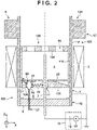
- Fig. 2 shows the arrangement of an ionization gauge 100 according to the first embodiment.
- the ionization gauge 100 can be configured as, for example, a reverse magnetron type gauge, but is not limited to this.
- a probe 102 can include a container 103 that forms a cathode 1, and an anode 2.
- the container 103 that forms the cathode 1 can include a tubular portion TP having, for example, a tubular shape such as a cylindrical shape.
- the anode 2 can have a rod shape.
- the cathode 1 can be arranged to surround the rod-shaped anode 2.
- a discharge space 4 can be defined by the anode 2 and the cathode 1.
- the container 103 can be made of a conductor such as a metal (for example, stainless steel).
- the anode 2 can be made of a conductor such as a metal (for example, molybdenum, tungsten, nickel, or titanium).
- the probe 102 can further include a magnet 3 that forms a magnetic field.
- the magnet 3 can be arranged to surround the tubular portion TP, and can have a ring shape.
- the magnet 3 can be, for example, a permanent magnet such as a ferrite magnet.
- One end (the side of the vacuum container 101) of the tubular portion TP of the container 103 can be opened, and the other end of the tubular portion TP can be sealed by an insulating sealing member 6.
- the anode 2 can be arranged to extend through the sealing member 6.
- the sealing member 6 can be made of, for example, alumina ceramic.
- An exchangeable cartridge 106 may be arranged in the container 103.
- the cartridge 106 can be a consumable component usable in the ionization gauge 100.
- the cartridge 106 can be, for example, a cathode structure.
- the cartridge 106 can include pole pieces (cathode plates) 104 and 105, and an inner tube 110.
- the pole pieces 104 and 105 can have a function of adjusting a magnetic field, and a function of surrounding the discharge space 4.
- the inner tube 110 can include an outer surface that is in contact with the inner surface of the container 103, and an inner surface surrounding the discharge space 4, and can support the pole pieces 104 and 105.
- the pole pieces 104 and 105 and the inner tube 110 can be made of a conductor such as a metal.
- the conductor that can form the pole pieces 104 and 105 may be a magnetic material (for example, stainless steel having magnetism), or may be a nonmagnetic material (for example, stainless steel that has no magnetism).
- the cartridge 106 is electrically connected to the tubular portion TP, and the pole pieces 104 and 105 and the inner tube 110 can form a part of the cathode 1. If the cartridge 106 has degraded due to collision of ions or the like against the cartridge 106, the degraded cartridge 106 is exchanged with a new cartridge 106, thereby recovering the function of the ionization gauge 100. In this example, the cartridge 106 is exchangeable. However, the cartridge 106 may be inseparably coupled with the tubular portion TP.
- the pole piece (first cathode plate) 105 can include a through hole 11 through which the anode 2 extends, and a storage portion 22 that stores an electromagnetic wave source 15.
- the through hole 11 is provided not to electrically connect the pole piece 105 and the anode 2, that is, to form a gap between the pole piece 105 and the anode 2.
- the electromagnetic wave source 15 can be, for example, a light source.
- the pole piece 105 is provided with a cover 25 that covers the electromagnetic wave source 15. When the cartridge 106 is detached from the tubular portion TP, the cover 25 can be detached from the tubular portion TP together with the pole piece 105. In this case, the cover 25 can be exchanged by exchanging the cartridge 106.
- the cover 25 can be made of a material (for example, silica) that passes an electromagnetic wave radiated from the electromagnetic wave source 15.
- the cover 25 prevents particles generated by sputtering the cathode 1 (mainly the cartridge 106) facing the discharge space 4 from being deposited on the electromagnetic wave source 15.
- the cover 25 can have, for example, a cylindrical shape.
- the pole piece (second cathode plate) 104 is arranged apart from the pole piece 105, and the discharge space 4 can be defined between the pole piece 105 and the pole piece 104.
- the pole piece 105 can be arranged between the pole piece 104 and the sealing member 6.
- the pole piece 105 can be arranged at an end of the inner tube 110 (an end on the side of the sealing member 6.
- the pole piece 104 can be arranged at the other end of the inner tube 110 (an end on the open end of the tubular portion TP).
- the pole piece 104 includes one or a plurality of through holes 10, and the vacuum container 101 and the discharge space 4 communicate via the one or the plurality of through holes 10.
- the cartridge 106 or the cathode 1 can further include a cathode plate (third cathode plate) 20 between the pole piece 105 (first cathode plate) and the pole piece 104 (second cathode plate).
- the cathode plate 20 can be arranged to be in contact with the pole piece 105.
- the cathode plate 20 includes a through hole to pass the anode 2.
- the cathode plate 20 can be configured to transmit the electromagnetic wave generated by the electromagnetic wave source 15 to the discharge space 4 surrounded by the pole piece 104, the cathode plate 20, and the inner tube 110 (tubular portion TP).
- the cathode plate 20 can be configured to form a gap 21 between the cathode plate 20 and the inner tube 110 and transmit, via the gap 21, the electromagnetic wave generated by the electromagnetic wave source 15 to the discharge space 4. Not only the electromagnetic wave generated by the electromagnetic wave source 15 but also electrons generated by the photoelectric effect upon irradiating a portion between the cathode plate 20 and the pole piece 105 in the inner tube 110 with the electromagnetic wave can be supplied to the discharge space 4 via the gap 21.
- the inner tube 110 can be made of the same material as the pole pieces 105 and 104.
- the anode 2 is electrically connected to the control unit 13.
- the control unit 13 can include a power supply 18 configured to apply a voltage to the anode 2, and a current detection unit 19 configured to measure a discharge current flowing between the anode 2 and the cathode 1.
- the discharge current detected by the current detection unit 19 has a correlation with the pressure in the discharge space 4, and the pressure can be calculated by a processor (not shown) based on the correlation. The pressure in the vacuum container 101 can thus be detected.
- Fig. 3A is a plan view of the pole piece 105 shown in Fig. 2 , which is viewed from the + direction of the z-axis in Fig. 2 . Note that in Fig. 3A , the cathode plate 20 is not illustrated.
- Fig. 3B is a sectional view of the pole piece 105 taken along a line A - A' in Fig. 3A .
- the pole piece (first cathode plate) 105 can include, between the storage portion 22 and the through hole 11, a passage 50 configured to pass the electromagnetic wave generated by the electromagnetic wave source 15.
- the passage 50 can be provided to form a linear path between the electromagnetic wave source 15 and the through hole 11.
- the passage 50 can extend in a radial direction to connect the storage portion 22 and the through hole 11.
- the passage 50 can be provided to face a space 5 surrounded by the pole piece 105, the sealing member 6, and the tubular portion TP.
- the electromagnetic wave generated by the electromagnetic wave source 15 irradiates the surface of the through hole 11 via the passage 50, and generates electrons on the surface of the through hole 11 by the photoelectric effect.
- the electromagnetic wave generated by the electromagnetic wave source 15 can directly irradiate the surface of the through hole 11, and can also be reflected by the surface of the passage 50 and/or the anode 2 and then irradiate the surface of the through hole 11.
- a part of the electromagnetic wave generated by the electromagnetic wave source 15 can generate electrons on the surface of the passage 50 by the photoelectric effect.
- the electrons generated on the surface of the through hole 11 and the surface of the passage 50 can be supplied to the discharge space 4.
- the inter-electrode distance (the distance between the pole piece 105 and the anode 2) in the through hole 11 is relatively shorter than the inter-electrode distance in another space in the ionization gauge 100.
- the electric field in the through hole 11 is relatively large. For this reason, the electric field efficiently concentrates in a bending portion (projection) 60 formed at the boundary between the passage 50 and the through hole 11, and electrons can be generated by field emission from the bending portion (projection) 60. From the above, when the passage 50 is provided, the amount of electrons emitted to the discharge space 4 can be increased, and as a result, discharge inducing performance can be improved.
- the electromagnetic wave source 15 can generate an electromagnetic wave, for example, soft x-rays.
- the storage portion 22 that stores the electromagnetic wave source 15 can be, for example, a through hole or a concave portion provided in the pole piece 105.
- the storage portion 22 may be in contact with the electromagnetic wave source 15 or not.
- the storage portion 22 may hold the electromagnetic wave source 15 or not.
- the distance between the storage portion 22 and the inner tube 110 may be shorter than the distance between the storage portion 22 and the anode 2.
- the distance between the electromagnetic wave source 15 and the inner tube 110 may be shorter than the distance between the electromagnetic wave source 15 and the anode 2. This arrangement can reduce the attenuation of the electromagnetic wave that is generated by the electromagnetic wave source 15 and enters the inner tube 110. This is advantageous in increasing the electrons emitted from the inner tube 110 to the discharge space 4 by the photoelectric effect.
- the cathode plate 20 can be arranged between the electromagnetic wave source 15 and the discharge space 4.
- the cathode plate 20 can prevent particles generated by sputtering the cathode 1 (mainly the cartridge 106) facing the discharge space 4 from being deposited on the electromagnetic wave source 15.
- a surface of the pole piece 105 on the side of the discharge space 4 can include a portion that tilts to provide the electromagnetic wave radiated from the electromagnetic wave source 15 to the inner tube 110 and/or the gap 21.
- Power supply to the electromagnetic wave source 15 can be done by a power cable 27.
- the power cable 27 can be extracted to the outside of the container 103 via the sealing member 6.
- the arrangement for extracting the power cable 27 and the anode 2 to the outside via the sealing member 6 common to these is advantageous in simplifying the structure of the ionization gauge 100.
- At least one of the electromagnetic wave source 15 and the cover 25 may be coated with a film made of a material of a low work function, for example, a metal. If the electromagnetic wave enters the material of the low work function, electrons are efficiently generated. Hence, when at least one of the electromagnetic wave source 15 and the cover 25 is coated with the film made of the material of the low work function, electrons can efficiently be generated.
- the inner surface of the inner tube 110 may be coated with a material whose work function is lower than that of the base material of the inner tube 110.
- Figs. 4A , 5A, and 5B show the arrangement of an ionization gauge 100 according to the second embodiment.
- Fig. 5A is a plan view of a pole piece 105 shown in Fig. 4A , which is viewed from the + direction of the z-axis in Fig. 4A .
- a cathode plate 20 is not illustrated.
- Fig. 5B is a sectional view of the pole piece 105 taken along a line B - B' in Fig. 5A . Matters that are not mentioned as the second embodiment can comply with the first embodiment.
- the pole piece (first cathode plate) 105 can include, between a storage portion 22 and a through hole 11, a passage 70 configured to pass an electromagnetic wave generated by an electromagnetic wave source 15.
- the passage 70 can be a through hole that makes the storage portion 22 and the through hole 11 communicate.
- the passage 70 can be provided to form a linear path between the electromagnetic wave source 15 and the through hole 11.
- the passage 70 can extend in a radial direction to connect the storage portion 22 and the through hole 11.
- the passage 70 may include a portion extending between the storage portion 22 and an inner tube 110.
- Figs. 4B , 5C, and 5D show the arrangement of a modification of the ionization gauge 100 according to the second embodiment.
- Fig. 5C is a plan view of the pole piece 105 shown in Fig. 4B , which is viewed from the + direction of the z-axis in Fig. 4B .
- the cathode plate 20 is not illustrated.
- Fig. 5D is a sectional view of the pole piece 105 taken along a line B - B' in Fig. 5C .
- the passage 70 is formed as a groove or a slit exposed to a space 5. This arrangement is excellent because machining is easy.
- the passage 70 may include a portion extending between the storage portion 22 and the inner tube 110.
- Figs. 6 , 7A, and 7B show the arrangement of an ionization gauge 100 according to the third embodiment.
- Fig. 7A is a plan view of a pole piece 105 shown in Fig. 6 , which is viewed from the + direction of the z-axis in Fig. 6 .
- Fig. 7B is a sectional view of the pole piece 105 taken along a line C - C' in Fig. 7A .
- Matters that are not mentioned as the third embodiment can comply with the first or second embodiment.
- the pole piece (first cathode plate) 105 can include, between a storage portion 22 and a through hole 11, a passage 80 configured to pass an electromagnetic wave generated by an electromagnetic wave source 15.
- the passage 80 can be provided to face a space 5 surrounded by the pole piece 105, a sealing member 6, and a tubular portion TP.
- the passage 80 may be a through hole that makes the storage portion 22 and the through hole 11 communicate.
- the passage 80 can be provided to form a linear path between the electromagnetic wave source 15 and the through hole 11.
- the passage 80 can extend in a radial direction to connect the storage portion 22 and the through hole 11.
- the electromagnetic wave radiated from the electromagnetic wave source 15 can move in the passage 80 while being reflected and reach the surface of the through hole 11.
- a surface of the pole piece 105 on the side of the space 5 can include a portion that tilts to provide the electromagnetic wave radiated from the electromagnetic wave source 15 to an inner tube 110 and/or a gap 21.
Landscapes
- Physics & Mathematics (AREA)
- General Physics & Mathematics (AREA)
- Measuring Fluid Pressure (AREA)
Abstract
Description
- The present invention relates to an ionization gauge and a cartridge.
- In an ionization gauge, a gas is ionized by applying a voltage between an anode and a cathode and thus causing discharge, and a current flowing between the cathode and the anode is measured to detect a pressure. The ionization gauge can be provided with an inducing unit configured to promote discharge between the anode and the cathode. In
PTL 1, a cathode is irradiated with an electromagnetic wave, and electrons are emitted from the cathode by the photoelectric effect, thereby inducing discharge. However, in long-time use, substances may be deposited on the surface of the electrode, and discharge may be difficult to induce. - PTL 1:
Japanese Patent No. 6177492 - The present invention provides a technique advantageous in suppressing lowering of discharge inducing performance in an ionization gauge.
- According to the first aspect of the present invention, there is provided an ionization gauge comprising an anode, a cathode, and an electromagnetic wave source, wherein the cathode comprises a first cathode plate including a through hole through which the anode passes, and a storage portion configured to store the electromagnetic wave source, and wherein the first cathode plate includes, between the storage portion and the through hole, a passage configured to pass an electromagnetic wave generated by the electromagnetic wave source.
- According to the second aspect of the present invention, there is provided a cartridge used in an ionization gauge including an anode, an electromagnetic wave source, and a container, the cartridge comprising a first cathode plate including a through hole through which the anode passes, a storage portion configured to store the electromagnetic wave source, and wherein the first cathode plate includes, between the storage portion and the through hole, a passage configured to pass an electromagnetic wave generated by the electromagnetic wave source.
- Further features of the present invention will become apparent from the following description of exemplary embodiments with reference to the attached drawings.
-
-
Fig. 1 is a view showing a vacuum processing apparatus according to an embodiment and an ionization gauge attached to it; -
Fig. 2 is a view showing the arrangement of an ionization gauge according to the first embodiment; -
Fig. 3A is a view showing the arrangement of the ionization gauge according to the first embodiment; -
Fig. 3B is a view showing the arrangement of the ionization gauge according to the first embodiment; -
Fig. 4A is a view showing the arrangement of an ionization gauge according to the second embodiment; -
Fig. 4B is a view showing the arrangement of a modification of the ionization gauge according to the second embodiment; -
Fig. 5A is a view showing the arrangement of the ionization gauge according to the second embodiment; -
Fig. 5B is a view showing the arrangement of the ionization gauge according to the second embodiment; -
Fig. 5C is a view showing the arrangement of the modification of the ionization gauge according to the second embodiment; -
Fig. 5D is a view showing the arrangement of the modification of the ionization gauge according to the second embodiment; -
Fig. 6 is a view showing the arrangement of an ionization gauge according to the third embodiment; -
Fig. 7A is a view showing the arrangement of the ionization gauge according to the third embodiment; and -
Fig. 7B is a view showing the arrangement of the ionization gauge according to the third embodiment. - Hereinafter, the embodiments will be described in detail with reference to the accompanying drawings. It should be noted that the following embodiments are not intended to limit the scope of the appended claims of the present invention. A plurality of features are described in the embodiments. However, not all of the plurality of features are necessarily essential to the present invention, and the plurality of features may arbitrarily be combined. Also, the same reference numerals denote the same or similar parts throughout the accompanying drawings, and a repetitive description thereof will be omitted.
-
Fig. 1 shows a vacuum processing apparatus S according to an embodiment and anionization gauge 100 attached to it. The vacuum processing apparatus S can be, for example, a deposition apparatus. Examples of the deposition apparatus are a sputtering apparatus, a PVD apparatus, and a CVD apparatus. The vacuum processing apparatus S may be a surface treatment processing such as an ashing apparatus or a dry etching apparatus. - The
ionization gauge 100 can include aprobe 102, and acontrol unit 13 connected to theprobe 102. The vacuum processing apparatus S includes avacuum container 101, and can process a processing target object such as a substrate in thevacuum container 101. Theprobe 102 is attached to an opening portion provided in the wall of thevacuum container 101 while holding airtightness. In an example, theprobe 102 can be connected via aflange 8 of thevacuum container 101. Thecontrol unit 13 and theprobe 102 may be configured to be separable from each other or may be integrated. -
Fig. 2 shows the arrangement of anionization gauge 100 according to the first embodiment. Theionization gauge 100 can be configured as, for example, a reverse magnetron type gauge, but is not limited to this. Aprobe 102 can include acontainer 103 that forms acathode 1, and ananode 2. Thecontainer 103 that forms thecathode 1 can include a tubular portion TP having, for example, a tubular shape such as a cylindrical shape. Theanode 2 can have a rod shape. Thecathode 1 can be arranged to surround the rod-shaped anode 2. Adischarge space 4 can be defined by theanode 2 and thecathode 1. Thecontainer 103 can be made of a conductor such as a metal (for example, stainless steel). Theanode 2 can be made of a conductor such as a metal (for example, molybdenum, tungsten, nickel, or titanium). Theprobe 102 can further include amagnet 3 that forms a magnetic field. Themagnet 3 can be arranged to surround the tubular portion TP, and can have a ring shape. Themagnet 3 can be, for example, a permanent magnet such as a ferrite magnet. One end (the side of the vacuum container 101) of the tubular portion TP of thecontainer 103 can be opened, and the other end of the tubular portion TP can be sealed by an insulating sealingmember 6. In an example, theanode 2 can be arranged to extend through the sealingmember 6. The sealingmember 6 can be made of, for example, alumina ceramic. - An
exchangeable cartridge 106 may be arranged in thecontainer 103. Thecartridge 106 can be a consumable component usable in theionization gauge 100. Thecartridge 106 can be, for example, a cathode structure. Thecartridge 106 can include pole pieces (cathode plates) 104 and 105, and aninner tube 110. Thepole pieces discharge space 4. Theinner tube 110 can include an outer surface that is in contact with the inner surface of thecontainer 103, and an inner surface surrounding thedischarge space 4, and can support thepole pieces pole pieces inner tube 110 can be made of a conductor such as a metal. The conductor that can form thepole pieces - The
cartridge 106 is electrically connected to the tubular portion TP, and thepole pieces inner tube 110 can form a part of thecathode 1. If thecartridge 106 has degraded due to collision of ions or the like against thecartridge 106, thedegraded cartridge 106 is exchanged with anew cartridge 106, thereby recovering the function of theionization gauge 100. In this example, thecartridge 106 is exchangeable. However, thecartridge 106 may be inseparably coupled with the tubular portion TP. - The pole piece (first cathode plate) 105 can include a through
hole 11 through which theanode 2 extends, and astorage portion 22 that stores anelectromagnetic wave source 15. The throughhole 11 is provided not to electrically connect thepole piece 105 and theanode 2, that is, to form a gap between thepole piece 105 and theanode 2. Theelectromagnetic wave source 15 can be, for example, a light source. Thepole piece 105 is provided with acover 25 that covers theelectromagnetic wave source 15. When thecartridge 106 is detached from the tubular portion TP, thecover 25 can be detached from the tubular portion TP together with thepole piece 105. In this case, thecover 25 can be exchanged by exchanging thecartridge 106. Thecover 25 can be made of a material (for example, silica) that passes an electromagnetic wave radiated from theelectromagnetic wave source 15. Thecover 25 prevents particles generated by sputtering the cathode 1 (mainly the cartridge 106) facing thedischarge space 4 from being deposited on theelectromagnetic wave source 15. Thecover 25 can have, for example, a cylindrical shape. - The pole piece (second cathode plate) 104 is arranged apart from the
pole piece 105, and thedischarge space 4 can be defined between thepole piece 105 and thepole piece 104. Thepole piece 105 can be arranged between thepole piece 104 and the sealingmember 6. Thepole piece 105 can be arranged at an end of the inner tube 110 (an end on the side of the sealingmember 6. Thepole piece 104 can be arranged at the other end of the inner tube 110 (an end on the open end of the tubular portion TP). Thepole piece 104 includes one or a plurality of throughholes 10, and thevacuum container 101 and thedischarge space 4 communicate via the one or the plurality of throughholes 10. - The
cartridge 106 or thecathode 1 can further include a cathode plate (third cathode plate) 20 between the pole piece 105 (first cathode plate) and the pole piece 104 (second cathode plate). Thecathode plate 20 can be arranged to be in contact with thepole piece 105. Thecathode plate 20 includes a through hole to pass theanode 2. Thecathode plate 20 can be configured to transmit the electromagnetic wave generated by theelectromagnetic wave source 15 to thedischarge space 4 surrounded by thepole piece 104, thecathode plate 20, and the inner tube 110 (tubular portion TP). For example, thecathode plate 20 can be configured to form agap 21 between thecathode plate 20 and theinner tube 110 and transmit, via thegap 21, the electromagnetic wave generated by theelectromagnetic wave source 15 to thedischarge space 4. Not only the electromagnetic wave generated by theelectromagnetic wave source 15 but also electrons generated by the photoelectric effect upon irradiating a portion between thecathode plate 20 and thepole piece 105 in theinner tube 110 with the electromagnetic wave can be supplied to thedischarge space 4 via thegap 21. Theinner tube 110 can be made of the same material as thepole pieces - The
anode 2 is electrically connected to thecontrol unit 13. Thecontrol unit 13 can include apower supply 18 configured to apply a voltage to theanode 2, and acurrent detection unit 19 configured to measure a discharge current flowing between theanode 2 and thecathode 1. The discharge current detected by thecurrent detection unit 19 has a correlation with the pressure in thedischarge space 4, and the pressure can be calculated by a processor (not shown) based on the correlation. The pressure in thevacuum container 101 can thus be detected. -
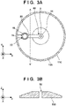
Fig. 3A is a plan view of thepole piece 105 shown inFig. 2 , which is viewed from the + direction of the z-axis inFig. 2 . Note that inFig. 3A , thecathode plate 20 is not illustrated.Fig. 3B is a sectional view of thepole piece 105 taken along a line A - A' inFig. 3A . As shown inFigs. 2 ,3A, and 3B , the pole piece (first cathode plate) 105 can include, between thestorage portion 22 and the throughhole 11, apassage 50 configured to pass the electromagnetic wave generated by theelectromagnetic wave source 15. Thepassage 50 can be provided to form a linear path between theelectromagnetic wave source 15 and the throughhole 11. Thepassage 50 can extend in a radial direction to connect thestorage portion 22 and the throughhole 11. Thepassage 50 can be provided to face aspace 5 surrounded by thepole piece 105, the sealingmember 6, and the tubular portion TP. When thepassage 50 is provided in thepole piece 105, the electromagnetic wave generated by theelectromagnetic wave source 15 irradiates the surface of the throughhole 11 via thepassage 50, and generates electrons on the surface of the throughhole 11 by the photoelectric effect. The electromagnetic wave generated by theelectromagnetic wave source 15 can directly irradiate the surface of the throughhole 11, and can also be reflected by the surface of thepassage 50 and/or theanode 2 and then irradiate the surface of the throughhole 11. A part of the electromagnetic wave generated by theelectromagnetic wave source 15 can generate electrons on the surface of thepassage 50 by the photoelectric effect. The electrons generated on the surface of the throughhole 11 and the surface of thepassage 50 can be supplied to thedischarge space 4. In addition, the inter-electrode distance (the distance between thepole piece 105 and the anode 2) in the throughhole 11 is relatively shorter than the inter-electrode distance in another space in theionization gauge 100. Hence, the electric field in the throughhole 11 is relatively large. For this reason, the electric field efficiently concentrates in a bending portion (projection) 60 formed at the boundary between thepassage 50 and the throughhole 11, and electrons can be generated by field emission from the bending portion (projection) 60. From the above, when thepassage 50 is provided, the amount of electrons emitted to thedischarge space 4 can be increased, and as a result, discharge inducing performance can be improved. - The
electromagnetic wave source 15 can generate an electromagnetic wave, for example, soft x-rays. Thestorage portion 22 that stores theelectromagnetic wave source 15 can be, for example, a through hole or a concave portion provided in thepole piece 105. Thestorage portion 22 may be in contact with theelectromagnetic wave source 15 or not. Thestorage portion 22 may hold theelectromagnetic wave source 15 or not. In an example, the distance between thestorage portion 22 and theinner tube 110 may be shorter than the distance between thestorage portion 22 and theanode 2. In another viewpoint, the distance between theelectromagnetic wave source 15 and theinner tube 110 may be shorter than the distance between theelectromagnetic wave source 15 and theanode 2. This arrangement can reduce the attenuation of the electromagnetic wave that is generated by theelectromagnetic wave source 15 and enters theinner tube 110. This is advantageous in increasing the electrons emitted from theinner tube 110 to thedischarge space 4 by the photoelectric effect. - The
cathode plate 20 can be arranged between theelectromagnetic wave source 15 and thedischarge space 4. Thecathode plate 20 can prevent particles generated by sputtering the cathode 1 (mainly the cartridge 106) facing thedischarge space 4 from being deposited on theelectromagnetic wave source 15. In an example, a surface of thepole piece 105 on the side of thedischarge space 4 can include a portion that tilts to provide the electromagnetic wave radiated from theelectromagnetic wave source 15 to theinner tube 110 and/or thegap 21. Power supply to theelectromagnetic wave source 15 can be done by apower cable 27. Thepower cable 27 can be extracted to the outside of thecontainer 103 via the sealingmember 6. The arrangement for extracting thepower cable 27 and theanode 2 to the outside via the sealingmember 6 common to these is advantageous in simplifying the structure of theionization gauge 100. - At least one of the
electromagnetic wave source 15 and thecover 25 may be coated with a film made of a material of a low work function, for example, a metal. If the electromagnetic wave enters the material of the low work function, electrons are efficiently generated. Hence, when at least one of theelectromagnetic wave source 15 and thecover 25 is coated with the film made of the material of the low work function, electrons can efficiently be generated. In addition, the inner surface of theinner tube 110 may be coated with a material whose work function is lower than that of the base material of theinner tube 110. -
Figs. 4A ,5A, and 5B show the arrangement of anionization gauge 100 according to the second embodiment. Here,Fig. 5A is a plan view of apole piece 105 shown inFig. 4A , which is viewed from the + direction of the z-axis inFig. 4A . Note that inFig. 5A , acathode plate 20 is not illustrated.Fig. 5B is a sectional view of thepole piece 105 taken along a line B - B' inFig. 5A . Matters that are not mentioned as the second embodiment can comply with the first embodiment. - As shown in
Figs. 4A ,5A, and 5B , the pole piece (first cathode plate) 105 can include, between astorage portion 22 and a throughhole 11, apassage 70 configured to pass an electromagnetic wave generated by anelectromagnetic wave source 15. Thepassage 70 can be a through hole that makes thestorage portion 22 and the throughhole 11 communicate. Thepassage 70 can be provided to form a linear path between theelectromagnetic wave source 15 and the throughhole 11. Thepassage 70 can extend in a radial direction to connect thestorage portion 22 and the throughhole 11. When thepassage 70 is formed as a through hole, the electromagnetic wave radiated from theelectromagnetic wave source 15 can be confined in thepassage 70, and the electromagnetic wave can therefore more efficiently reach the surface of the throughhole 11. Thepassage 70 may include a portion extending between thestorage portion 22 and aninner tube 110. -
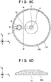
Figs. 4B ,5C, and 5D show the arrangement of a modification of theionization gauge 100 according to the second embodiment. Here,Fig. 5C is a plan view of thepole piece 105 shown inFig. 4B , which is viewed from the + direction of the z-axis inFig. 4B . Note that inFig. 5C , thecathode plate 20 is not illustrated.Fig. 5D is a sectional view of thepole piece 105 taken along a line B - B' inFig. 5C . In the modification, thepassage 70 is formed as a groove or a slit exposed to aspace 5. This arrangement is excellent because machining is easy. Thepassage 70 may include a portion extending between thestorage portion 22 and theinner tube 110. -
Figs. 6 ,7A, and 7B show the arrangement of anionization gauge 100 according to the third embodiment. Here,Fig. 7A is a plan view of apole piece 105 shown inFig. 6 , which is viewed from the + direction of the z-axis inFig. 6 .Fig. 7B is a sectional view of thepole piece 105 taken along a line C - C' inFig. 7A . Matters that are not mentioned as the third embodiment can comply with the first or second embodiment. - As shown in
Figs. 6 ,7A, and 7B , the pole piece (first cathode plate) 105 can include, between astorage portion 22 and a throughhole 11, apassage 80 configured to pass an electromagnetic wave generated by anelectromagnetic wave source 15. Thepassage 80 can be provided to face aspace 5 surrounded by thepole piece 105, a sealingmember 6, and a tubular portion TP. Thepassage 80 may be a through hole that makes thestorage portion 22 and the throughhole 11 communicate. Thepassage 80 can be provided to form a linear path between theelectromagnetic wave source 15 and the throughhole 11. Thepassage 80 can extend in a radial direction to connect thestorage portion 22 and the throughhole 11. The electromagnetic wave radiated from theelectromagnetic wave source 15 can move in thepassage 80 while being reflected and reach the surface of the throughhole 11. A surface of thepole piece 105 on the side of thespace 5 can include a portion that tilts to provide the electromagnetic wave radiated from theelectromagnetic wave source 15 to aninner tube 110 and/or agap 21. - The present invention is not limited to the above embodiments, and various changes and modifications can be made within the spirit and scope of the present invention. Therefore, to apprise the public of the scope of the present invention, the following claims are made.
Claims (12)
- An ionization gauge comprising an anode, a cathode, and an electromagnetic wave source, whereinthe cathode comprises a first cathode plate including a through hole through which the anode passes, and a storage portion configured to store the electromagnetic wave source, andwherein the first cathode plate includes, between the storage portion and the through hole, a passage configured to pass an electromagnetic wave generated by the electromagnetic wave source.
- The ionization gauge according to claim 1, wherein the cathode further includes a tubular portion configured to surround the anode and the first cathode plate, and a second cathode plate arranged in the tubular portion and including a through hole, and
one end of the tubular portion is opened, the other end of the tubular portion is sealed by a sealing member, and the first cathode plate is arranged between the second cathode plate and the sealing member. - The ionization gauge according to claim 2, wherein the passage faces a space surrounded by the first cathode plate, the sealing member, and the tubular portion.
- The ionization gauge according to claim 2, wherein the passage comprises a through hole configured to make the storage portion and the through hole communicate.
- The ionization gauge according to any one of claims 2 to 4, wherein the cathode further includes a third cathode plate between the first cathode plate and the second cathode plate, and
the third cathode plate is configured to transmit an electromagnetic wave generated by the electromagnetic wave source to a discharge space surrounded by the second cathode plate, the third cathode plate, and the tubular portion. - The ionization gauge according to any one of claims 1 to 5, wherein the passage is provided to form a linear path between the electromagnetic wave source and the through hole of the first cathode plate.
- A cartridge used in an ionization gauge including an anode, an electromagnetic wave source, and a container, the cartridge comprisinga first cathode plate including a through hole through which the anode passes, and a storage portion configured to store the electromagnetic wave source,wherein the first cathode plate includes, between the storage portion and the through hole, a passage configured to pass an electromagnetic wave generated by the electromagnetic wave source.
- The cartridge according to claim 7, further comprising a second cathode plate arranged apart from the first cathode plate and including a through hole, and an inner tube arranged in the container to support the first cathode plate and the second cathode plate.
- The cartridge according to claim 8, wherein one end of the container is opened, and the other end of the container is sealed by a sealing member, and
the passage faces a space between the first cathode plate and the sealing member. - The cartridge according to claim 8, wherein the passage comprises a through hole configured to make the storage portion and the through hole communicate.
- The cartridge according to any one of claims 8 to 10, further comprising a third cathode plate between the first cathode plate and the second cathode plate,
wherein the third cathode plate is configured to transmit an electromagnetic wave generated by the electromagnetic wave source to a space which is surrounded by the second cathode plate, the third cathode plate and the inner tube. - The cartridge according to any one of claims 7 to 11, wherein the passage is provided to form a linear path between the electromagnetic wave source and the through hole of the first cathode plate.
Applications Claiming Priority (1)
| Application Number | Priority Date | Filing Date | Title |
|---|---|---|---|
| PCT/JP2019/036191 WO2021049026A1 (en) | 2019-09-13 | 2019-09-13 | Ionization gauge and cartridge |
Publications (3)
| Publication Number | Publication Date |
|---|---|
| EP3998466A1 true EP3998466A1 (en) | 2022-05-18 |
| EP3998466A4 EP3998466A4 (en) | 2022-07-27 |
| EP3998466B1 EP3998466B1 (en) | 2023-11-01 |
Family
ID=70413760
Family Applications (1)
| Application Number | Title | Priority Date | Filing Date |
|---|---|---|---|
| EP19944839.0A Active EP3998466B1 (en) | 2019-09-13 | 2019-09-13 | Ionization gauge and cartridge therefor |
Country Status (7)
| Country | Link |
|---|---|
| US (1) | US10969291B1 (en) |
| EP (1) | EP3998466B1 (en) |
| JP (1) | JP6687823B1 (en) |
| KR (1) | KR102390110B1 (en) |
| CN (1) | CN114341607B (en) |
| TW (1) | TWI758851B (en) |
| WO (1) | WO2021049026A1 (en) |
Families Citing this family (2)
| Publication number | Priority date | Publication date | Assignee | Title |
|---|---|---|---|---|
| JP7096628B1 (en) * | 2022-03-22 | 2022-07-06 | バキュームプロダクツ株式会社 | Septal pressure gauge and compound pressure gauge |
| USD989951S1 (en) * | 2022-03-24 | 2023-06-20 | Teoxane S.A. | Laboratory hand instrument and utensil |
Family Cites Families (7)
| Publication number | Priority date | Publication date | Assignee | Title |
|---|---|---|---|---|
| JPS4836306B1 (en) * | 1969-03-26 | 1973-11-02 | ||
| US5198772A (en) * | 1991-03-12 | 1993-03-30 | Mks Instruments, Inc. | Removable discharge initiating means for cold cathode discharge ionization gauge |
| US5157333A (en) * | 1991-03-12 | 1992-10-20 | Mks Instruments, Inc. | Discharge initiating means for cold cathode discharge ionization gauge |
| MX9709805A (en) * | 1995-06-09 | 1998-03-29 | Toshiba Kk | Impregnated cathode structure, cathode substrate used for the structure, electron gun structure using the cathode structure, and electron tube. |
| GB9906788D0 (en) * | 1999-03-24 | 1999-05-19 | Boc Group Plc | Vacuum gauge |
| JP5669411B2 (en) * | 2009-04-09 | 2015-02-12 | キヤノンアネルバ株式会社 | Cold cathode ionization vacuum gauge, vacuum processing apparatus equipped with the same, and discharge start auxiliary electrode |
| EP4016035A1 (en) * | 2017-03-13 | 2022-06-22 | Canon Anelva Corporation | Cold cathode ionization gauge and cold cathode ionization gauge cartridge |
-
2019
- 2019-09-13 KR KR1020227005335A patent/KR102390110B1/en active Active
- 2019-09-13 CN CN201980099766.0A patent/CN114341607B/en active Active
- 2019-09-13 EP EP19944839.0A patent/EP3998466B1/en active Active
- 2019-09-13 WO PCT/JP2019/036191 patent/WO2021049026A1/en not_active Ceased
- 2019-09-13 JP JP2020510148A patent/JP6687823B1/en active Active
-
2020
- 2020-09-08 TW TW109130687A patent/TWI758851B/en active
- 2020-09-14 US US17/019,419 patent/US10969291B1/en active Active
Also Published As
| Publication number | Publication date |
|---|---|
| US10969291B1 (en) | 2021-04-06 |
| WO2021049026A1 (en) | 2021-03-18 |
| JPWO2021049026A1 (en) | 2021-09-30 |
| CN114341607A (en) | 2022-04-12 |
| TWI758851B (en) | 2022-03-21 |
| KR20220025285A (en) | 2022-03-03 |
| TW202124931A (en) | 2021-07-01 |
| EP3998466B1 (en) | 2023-11-01 |
| JP6687823B1 (en) | 2020-04-28 |
| EP3998466A4 (en) | 2022-07-27 |
| US20210080336A1 (en) | 2021-03-18 |
| CN114341607B (en) | 2022-06-24 |
| KR102390110B1 (en) | 2022-04-25 |
Similar Documents
| Publication | Publication Date | Title |
|---|---|---|
| EP2618360B1 (en) | Target for X-ray generation, X-ray generator, and method for producing target for X-ray generation | |
| TWI667680B (en) | Ion generating device and hot electron emitting unit | |
| TWI625755B (en) | Insulation structure, ion source device, ion implantation device and insulation method | |
| US10969291B1 (en) | Ionization gauge and cartridge | |
| CN113272931A (en) | X-ray generating tube, X-ray generating apparatus, and X-ray imaging apparatus | |
| US10222287B2 (en) | Cold cathode ionization gauge and cold cathode ionization gauge cartridge | |
| US11092506B2 (en) | Ionization gauge and cartridge | |
| JP2006351374A (en) | Ion source | |
| US20220285123A1 (en) | Ion gun and ion milling machine | |
| JP5118607B2 (en) | Vacuum processing equipment | |
| WO2024224498A1 (en) | Charged particle beam device | |
| JP2004265800A (en) | Vacuum interrupter | |
| JPH04118837A (en) | Ion source |
Legal Events
| Date | Code | Title | Description |
|---|---|---|---|
| STAA | Information on the status of an ep patent application or granted ep patent |
Free format text: STATUS: THE INTERNATIONAL PUBLICATION HAS BEEN MADE |
|
| PUAI | Public reference made under article 153(3) epc to a published international application that has entered the european phase |
Free format text: ORIGINAL CODE: 0009012 |
|
| STAA | Information on the status of an ep patent application or granted ep patent |
Free format text: STATUS: REQUEST FOR EXAMINATION WAS MADE |
|
| 17P | Request for examination filed |
Effective date: 20220211 |
|
| AK | Designated contracting states |
Kind code of ref document: A1 Designated state(s): AL AT BE BG CH CY CZ DE DK EE ES FI FR GB GR HR HU IE IS IT LI LT LU LV MC MK MT NL NO PL PT RO RS SE SI SK SM TR |
|
| A4 | Supplementary search report drawn up and despatched |
Effective date: 20220623 |
|
| RIC1 | Information provided on ipc code assigned before grant |
Ipc: G01L 21/34 20060101AFI20220617BHEP |
|
| DAV | Request for validation of the european patent (deleted) | ||
| DAX | Request for extension of the european patent (deleted) | ||
| GRAP | Despatch of communication of intention to grant a patent |
Free format text: ORIGINAL CODE: EPIDOSNIGR1 |
|
| STAA | Information on the status of an ep patent application or granted ep patent |
Free format text: STATUS: GRANT OF PATENT IS INTENDED |
|
| INTG | Intention to grant announced |
Effective date: 20230601 |
|
| GRAS | Grant fee paid |
Free format text: ORIGINAL CODE: EPIDOSNIGR3 |
|
| GRAA | (expected) grant |
Free format text: ORIGINAL CODE: 0009210 |
|
| STAA | Information on the status of an ep patent application or granted ep patent |
Free format text: STATUS: THE PATENT HAS BEEN GRANTED |
|
| AK | Designated contracting states |
Kind code of ref document: B1 Designated state(s): AL AT BE BG CH CY CZ DE DK EE ES FI FR GB GR HR HU IE IS IT LI LT LU LV MC MK MT NL NO PL PT RO RS SE SI SK SM TR |
|
| REG | Reference to a national code |
Ref country code: GB Ref legal event code: FG4D |
|
| REG | Reference to a national code |
Ref country code: CH Ref legal event code: EP |
|
| REG | Reference to a national code |
Ref country code: IE Ref legal event code: FG4D |
|
| REG | Reference to a national code |
Ref country code: DE Ref legal event code: R096 Ref document number: 602019040881 Country of ref document: DE |
|
| REG | Reference to a national code |
Ref country code: LT Ref legal event code: MG9D |
|
| REG | Reference to a national code |
Ref country code: NL Ref legal event code: MP Effective date: 20231101 |
|
| PG25 | Lapsed in a contracting state [announced via postgrant information from national office to epo] |
Ref country code: GR Free format text: LAPSE BECAUSE OF FAILURE TO SUBMIT A TRANSLATION OF THE DESCRIPTION OR TO PAY THE FEE WITHIN THE PRESCRIBED TIME-LIMIT Effective date: 20240202 |
|
| PG25 | Lapsed in a contracting state [announced via postgrant information from national office to epo] |
Ref country code: IS Free format text: LAPSE BECAUSE OF FAILURE TO SUBMIT A TRANSLATION OF THE DESCRIPTION OR TO PAY THE FEE WITHIN THE PRESCRIBED TIME-LIMIT Effective date: 20240301 |
|
| PG25 | Lapsed in a contracting state [announced via postgrant information from national office to epo] |
Ref country code: LT Free format text: LAPSE BECAUSE OF FAILURE TO SUBMIT A TRANSLATION OF THE DESCRIPTION OR TO PAY THE FEE WITHIN THE PRESCRIBED TIME-LIMIT Effective date: 20231101 |
|
| REG | Reference to a national code |
Ref country code: AT Ref legal event code: MK05 Ref document number: 1627723 Country of ref document: AT Kind code of ref document: T Effective date: 20231101 |
|
| PG25 | Lapsed in a contracting state [announced via postgrant information from national office to epo] |
Ref country code: NL Free format text: LAPSE BECAUSE OF FAILURE TO SUBMIT A TRANSLATION OF THE DESCRIPTION OR TO PAY THE FEE WITHIN THE PRESCRIBED TIME-LIMIT Effective date: 20231101 |
|
| PG25 | Lapsed in a contracting state [announced via postgrant information from national office to epo] |
Ref country code: AT Free format text: LAPSE BECAUSE OF FAILURE TO SUBMIT A TRANSLATION OF THE DESCRIPTION OR TO PAY THE FEE WITHIN THE PRESCRIBED TIME-LIMIT Effective date: 20231101 |
|
| PG25 | Lapsed in a contracting state [announced via postgrant information from national office to epo] |
Ref country code: ES Free format text: LAPSE BECAUSE OF FAILURE TO SUBMIT A TRANSLATION OF THE DESCRIPTION OR TO PAY THE FEE WITHIN THE PRESCRIBED TIME-LIMIT Effective date: 20231101 |
|
| PG25 | Lapsed in a contracting state [announced via postgrant information from national office to epo] |
Ref country code: NL Free format text: LAPSE BECAUSE OF FAILURE TO SUBMIT A TRANSLATION OF THE DESCRIPTION OR TO PAY THE FEE WITHIN THE PRESCRIBED TIME-LIMIT Effective date: 20231101 Ref country code: LT Free format text: LAPSE BECAUSE OF FAILURE TO SUBMIT A TRANSLATION OF THE DESCRIPTION OR TO PAY THE FEE WITHIN THE PRESCRIBED TIME-LIMIT Effective date: 20231101 Ref country code: IS Free format text: LAPSE BECAUSE OF FAILURE TO SUBMIT A TRANSLATION OF THE DESCRIPTION OR TO PAY THE FEE WITHIN THE PRESCRIBED TIME-LIMIT Effective date: 20240301 Ref country code: GR Free format text: LAPSE BECAUSE OF FAILURE TO SUBMIT A TRANSLATION OF THE DESCRIPTION OR TO PAY THE FEE WITHIN THE PRESCRIBED TIME-LIMIT Effective date: 20240202 Ref country code: ES Free format text: LAPSE BECAUSE OF FAILURE TO SUBMIT A TRANSLATION OF THE DESCRIPTION OR TO PAY THE FEE WITHIN THE PRESCRIBED TIME-LIMIT Effective date: 20231101 Ref country code: BG Free format text: LAPSE BECAUSE OF FAILURE TO SUBMIT A TRANSLATION OF THE DESCRIPTION OR TO PAY THE FEE WITHIN THE PRESCRIBED TIME-LIMIT Effective date: 20240201 Ref country code: AT Free format text: LAPSE BECAUSE OF FAILURE TO SUBMIT A TRANSLATION OF THE DESCRIPTION OR TO PAY THE FEE WITHIN THE PRESCRIBED TIME-LIMIT Effective date: 20231101 Ref country code: PT Free format text: LAPSE BECAUSE OF FAILURE TO SUBMIT A TRANSLATION OF THE DESCRIPTION OR TO PAY THE FEE WITHIN THE PRESCRIBED TIME-LIMIT Effective date: 20240301 |
|
| PG25 | Lapsed in a contracting state [announced via postgrant information from national office to epo] |
Ref country code: SE Free format text: LAPSE BECAUSE OF FAILURE TO SUBMIT A TRANSLATION OF THE DESCRIPTION OR TO PAY THE FEE WITHIN THE PRESCRIBED TIME-LIMIT Effective date: 20231101 Ref country code: RS Free format text: LAPSE BECAUSE OF FAILURE TO SUBMIT A TRANSLATION OF THE DESCRIPTION OR TO PAY THE FEE WITHIN THE PRESCRIBED TIME-LIMIT Effective date: 20231101 Ref country code: PL Free format text: LAPSE BECAUSE OF FAILURE TO SUBMIT A TRANSLATION OF THE DESCRIPTION OR TO PAY THE FEE WITHIN THE PRESCRIBED TIME-LIMIT Effective date: 20231101 Ref country code: NO Free format text: LAPSE BECAUSE OF FAILURE TO SUBMIT A TRANSLATION OF THE DESCRIPTION OR TO PAY THE FEE WITHIN THE PRESCRIBED TIME-LIMIT Effective date: 20240201 Ref country code: LV Free format text: LAPSE BECAUSE OF FAILURE TO SUBMIT A TRANSLATION OF THE DESCRIPTION OR TO PAY THE FEE WITHIN THE PRESCRIBED TIME-LIMIT Effective date: 20231101 Ref country code: HR Free format text: LAPSE BECAUSE OF FAILURE TO SUBMIT A TRANSLATION OF THE DESCRIPTION OR TO PAY THE FEE WITHIN THE PRESCRIBED TIME-LIMIT Effective date: 20231101 |
|
| PG25 | Lapsed in a contracting state [announced via postgrant information from national office to epo] |
Ref country code: DK Free format text: LAPSE BECAUSE OF FAILURE TO SUBMIT A TRANSLATION OF THE DESCRIPTION OR TO PAY THE FEE WITHIN THE PRESCRIBED TIME-LIMIT Effective date: 20231101 |
|
| PG25 | Lapsed in a contracting state [announced via postgrant information from national office to epo] |
Ref country code: CZ Free format text: LAPSE BECAUSE OF FAILURE TO SUBMIT A TRANSLATION OF THE DESCRIPTION OR TO PAY THE FEE WITHIN THE PRESCRIBED TIME-LIMIT Effective date: 20231101 |
|
| PG25 | Lapsed in a contracting state [announced via postgrant information from national office to epo] |
Ref country code: SK Free format text: LAPSE BECAUSE OF FAILURE TO SUBMIT A TRANSLATION OF THE DESCRIPTION OR TO PAY THE FEE WITHIN THE PRESCRIBED TIME-LIMIT Effective date: 20231101 |
|
| PG25 | Lapsed in a contracting state [announced via postgrant information from national office to epo] |
Ref country code: SM Free format text: LAPSE BECAUSE OF FAILURE TO SUBMIT A TRANSLATION OF THE DESCRIPTION OR TO PAY THE FEE WITHIN THE PRESCRIBED TIME-LIMIT Effective date: 20231101 Ref country code: SK Free format text: LAPSE BECAUSE OF FAILURE TO SUBMIT A TRANSLATION OF THE DESCRIPTION OR TO PAY THE FEE WITHIN THE PRESCRIBED TIME-LIMIT Effective date: 20231101 Ref country code: IT Free format text: LAPSE BECAUSE OF FAILURE TO SUBMIT A TRANSLATION OF THE DESCRIPTION OR TO PAY THE FEE WITHIN THE PRESCRIBED TIME-LIMIT Effective date: 20231101 Ref country code: EE Free format text: LAPSE BECAUSE OF FAILURE TO SUBMIT A TRANSLATION OF THE DESCRIPTION OR TO PAY THE FEE WITHIN THE PRESCRIBED TIME-LIMIT Effective date: 20231101 Ref country code: DK Free format text: LAPSE BECAUSE OF FAILURE TO SUBMIT A TRANSLATION OF THE DESCRIPTION OR TO PAY THE FEE WITHIN THE PRESCRIBED TIME-LIMIT Effective date: 20231101 Ref country code: CZ Free format text: LAPSE BECAUSE OF FAILURE TO SUBMIT A TRANSLATION OF THE DESCRIPTION OR TO PAY THE FEE WITHIN THE PRESCRIBED TIME-LIMIT Effective date: 20231101 |
|
| REG | Reference to a national code |
Ref country code: DE Ref legal event code: R097 Ref document number: 602019040881 Country of ref document: DE |
|
| PLBE | No opposition filed within time limit |
Free format text: ORIGINAL CODE: 0009261 |
|
| STAA | Information on the status of an ep patent application or granted ep patent |
Free format text: STATUS: NO OPPOSITION FILED WITHIN TIME LIMIT |
|
| 26N | No opposition filed |
Effective date: 20240802 |
|
| PG25 | Lapsed in a contracting state [announced via postgrant information from national office to epo] |
Ref country code: SI Free format text: LAPSE BECAUSE OF FAILURE TO SUBMIT A TRANSLATION OF THE DESCRIPTION OR TO PAY THE FEE WITHIN THE PRESCRIBED TIME-LIMIT Effective date: 20231101 |
|
| PG25 | Lapsed in a contracting state [announced via postgrant information from national office to epo] |
Ref country code: SI Free format text: LAPSE BECAUSE OF FAILURE TO SUBMIT A TRANSLATION OF THE DESCRIPTION OR TO PAY THE FEE WITHIN THE PRESCRIBED TIME-LIMIT Effective date: 20231101 |
|
| PG25 | Lapsed in a contracting state [announced via postgrant information from national office to epo] |
Ref country code: MC Free format text: LAPSE BECAUSE OF FAILURE TO SUBMIT A TRANSLATION OF THE DESCRIPTION OR TO PAY THE FEE WITHIN THE PRESCRIBED TIME-LIMIT Effective date: 20231101 |
|
| REG | Reference to a national code |
Ref country code: CH Ref legal event code: PL |
|
| PG25 | Lapsed in a contracting state [announced via postgrant information from national office to epo] |
Ref country code: LU Free format text: LAPSE BECAUSE OF NON-PAYMENT OF DUE FEES Effective date: 20240913 |
|
| REG | Reference to a national code |
Ref country code: BE Ref legal event code: MM Effective date: 20240930 |
|
| PG25 | Lapsed in a contracting state [announced via postgrant information from national office to epo] |
Ref country code: BE Free format text: LAPSE BECAUSE OF NON-PAYMENT OF DUE FEES Effective date: 20240930 |
|
| PG25 | Lapsed in a contracting state [announced via postgrant information from national office to epo] |
Ref country code: CH Free format text: LAPSE BECAUSE OF NON-PAYMENT OF DUE FEES Effective date: 20240930 |
|
| PG25 | Lapsed in a contracting state [announced via postgrant information from national office to epo] |
Ref country code: IE Free format text: LAPSE BECAUSE OF NON-PAYMENT OF DUE FEES Effective date: 20240913 |
|
| PG25 | Lapsed in a contracting state [announced via postgrant information from national office to epo] |
Ref country code: FI Free format text: LAPSE BECAUSE OF FAILURE TO SUBMIT A TRANSLATION OF THE DESCRIPTION OR TO PAY THE FEE WITHIN THE PRESCRIBED TIME-LIMIT Effective date: 20231101 |
|
| PGFP | Annual fee paid to national office [announced via postgrant information from national office to epo] |
Ref country code: DE Payment date: 20250730 Year of fee payment: 7 |
|
| PGFP | Annual fee paid to national office [announced via postgrant information from national office to epo] |
Ref country code: GB Payment date: 20250731 Year of fee payment: 7 |
|
| PGFP | Annual fee paid to national office [announced via postgrant information from national office to epo] |
Ref country code: FR Payment date: 20250808 Year of fee payment: 7 |
|
| PG25 | Lapsed in a contracting state [announced via postgrant information from national office to epo] |
Ref country code: RO Free format text: LAPSE BECAUSE OF FAILURE TO SUBMIT A TRANSLATION OF THE DESCRIPTION OR TO PAY THE FEE WITHIN THE PRESCRIBED TIME-LIMIT Effective date: 20231101 |
|
| PG25 | Lapsed in a contracting state [announced via postgrant information from national office to epo] |
Ref country code: CY Free format text: LAPSE BECAUSE OF FAILURE TO SUBMIT A TRANSLATION OF THE DESCRIPTION OR TO PAY THE FEE WITHIN THE PRESCRIBED TIME-LIMIT; INVALID AB INITIO Effective date: 20190913 |
|
| PG25 | Lapsed in a contracting state [announced via postgrant information from national office to epo] |
Ref country code: HU Free format text: LAPSE BECAUSE OF FAILURE TO SUBMIT A TRANSLATION OF THE DESCRIPTION OR TO PAY THE FEE WITHIN THE PRESCRIBED TIME-LIMIT; INVALID AB INITIO Effective date: 20190913 |