EP3998441A1 - Indoor unit of refrigeration device - Google Patents
Indoor unit of refrigeration device Download PDFInfo
- Publication number
- EP3998441A1 EP3998441A1 EP20840388.1A EP20840388A EP3998441A1 EP 3998441 A1 EP3998441 A1 EP 3998441A1 EP 20840388 A EP20840388 A EP 20840388A EP 3998441 A1 EP3998441 A1 EP 3998441A1
- Authority
- EP
- European Patent Office
- Prior art keywords
- indoor unit
- gas sensor
- heat exchanger
- refrigerant
- indoor
- Prior art date
- Legal status (The legal status is an assumption and is not a legal conclusion. Google has not performed a legal analysis and makes no representation as to the accuracy of the status listed.)
- Granted
Links
Images




Classifications
-
- F—MECHANICAL ENGINEERING; LIGHTING; HEATING; WEAPONS; BLASTING
- F24—HEATING; RANGES; VENTILATING
- F24F—AIR-CONDITIONING; AIR-HUMIDIFICATION; VENTILATION; USE OF AIR CURRENTS FOR SCREENING
- F24F1/00—Room units for air-conditioning, e.g. separate or self-contained units or units receiving primary air from a central station
- F24F1/0007—Indoor units, e.g. fan coil units
- F24F1/0043—Indoor units, e.g. fan coil units characterised by mounting arrangements
- F24F1/0047—Indoor units, e.g. fan coil units characterised by mounting arrangements mounted in the ceiling or at the ceiling
-
- F—MECHANICAL ENGINEERING; LIGHTING; HEATING; WEAPONS; BLASTING
- F24—HEATING; RANGES; VENTILATING
- F24F—AIR-CONDITIONING; AIR-HUMIDIFICATION; VENTILATION; USE OF AIR CURRENTS FOR SCREENING
- F24F1/00—Room units for air-conditioning, e.g. separate or self-contained units or units receiving primary air from a central station
- F24F1/0007—Indoor units, e.g. fan coil units
- F24F1/0059—Indoor units, e.g. fan coil units characterised by heat exchangers
- F24F1/0063—Indoor units, e.g. fan coil units characterised by heat exchangers by the mounting or arrangement of the heat exchangers
-
- F—MECHANICAL ENGINEERING; LIGHTING; HEATING; WEAPONS; BLASTING
- F24—HEATING; RANGES; VENTILATING
- F24F—AIR-CONDITIONING; AIR-HUMIDIFICATION; VENTILATION; USE OF AIR CURRENTS FOR SCREENING
- F24F1/00—Room units for air-conditioning, e.g. separate or self-contained units or units receiving primary air from a central station
- F24F1/0007—Indoor units, e.g. fan coil units
- F24F1/0071—Indoor units, e.g. fan coil units with means for purifying supplied air
- F24F1/0073—Indoor units, e.g. fan coil units with means for purifying supplied air characterised by the mounting or arrangement of filters
-
- F—MECHANICAL ENGINEERING; LIGHTING; HEATING; WEAPONS; BLASTING
- F24—HEATING; RANGES; VENTILATING
- F24F—AIR-CONDITIONING; AIR-HUMIDIFICATION; VENTILATION; USE OF AIR CURRENTS FOR SCREENING
- F24F11/00—Control or safety arrangements
- F24F11/30—Control or safety arrangements for purposes related to the operation of the system, e.g. for safety or monitoring
-
- F—MECHANICAL ENGINEERING; LIGHTING; HEATING; WEAPONS; BLASTING
- F24—HEATING; RANGES; VENTILATING
- F24F—AIR-CONDITIONING; AIR-HUMIDIFICATION; VENTILATION; USE OF AIR CURRENTS FOR SCREENING
- F24F11/00—Control or safety arrangements
- F24F11/30—Control or safety arrangements for purposes related to the operation of the system, e.g. for safety or monitoring
- F24F11/32—Responding to malfunctions or emergencies
- F24F11/36—Responding to malfunctions or emergencies to leakage of heat-exchange fluid
-
- F—MECHANICAL ENGINEERING; LIGHTING; HEATING; WEAPONS; BLASTING
- F24—HEATING; RANGES; VENTILATING
- F24F—AIR-CONDITIONING; AIR-HUMIDIFICATION; VENTILATION; USE OF AIR CURRENTS FOR SCREENING
- F24F11/00—Control or safety arrangements
- F24F11/89—Arrangement or mounting of control or safety devices
-
- F—MECHANICAL ENGINEERING; LIGHTING; HEATING; WEAPONS; BLASTING
- F24—HEATING; RANGES; VENTILATING
- F24F—AIR-CONDITIONING; AIR-HUMIDIFICATION; VENTILATION; USE OF AIR CURRENTS FOR SCREENING
- F24F13/00—Details common to, or for air-conditioning, air-humidification, ventilation or use of air currents for screening
- F24F13/20—Casings or covers
-
- F—MECHANICAL ENGINEERING; LIGHTING; HEATING; WEAPONS; BLASTING
- F24—HEATING; RANGES; VENTILATING
- F24F—AIR-CONDITIONING; AIR-HUMIDIFICATION; VENTILATION; USE OF AIR CURRENTS FOR SCREENING
- F24F13/00—Details common to, or for air-conditioning, air-humidification, ventilation or use of air currents for screening
- F24F13/22—Means for preventing condensation or evacuating condensate
- F24F13/222—Means for preventing condensation or evacuating condensate for evacuating condensate
-
- F—MECHANICAL ENGINEERING; LIGHTING; HEATING; WEAPONS; BLASTING
- F25—REFRIGERATION OR COOLING; COMBINED HEATING AND REFRIGERATION SYSTEMS; HEAT PUMP SYSTEMS; MANUFACTURE OR STORAGE OF ICE; LIQUEFACTION SOLIDIFICATION OF GASES
- F25B—REFRIGERATION MACHINES, PLANTS OR SYSTEMS; COMBINED HEATING AND REFRIGERATION SYSTEMS; HEAT PUMP SYSTEMS
- F25B13/00—Compression machines, plants or systems, with reversible cycle
-
- F—MECHANICAL ENGINEERING; LIGHTING; HEATING; WEAPONS; BLASTING
- F25—REFRIGERATION OR COOLING; COMBINED HEATING AND REFRIGERATION SYSTEMS; HEAT PUMP SYSTEMS; MANUFACTURE OR STORAGE OF ICE; LIQUEFACTION SOLIDIFICATION OF GASES
- F25B—REFRIGERATION MACHINES, PLANTS OR SYSTEMS; COMBINED HEATING AND REFRIGERATION SYSTEMS; HEAT PUMP SYSTEMS
- F25B49/00—Arrangement or mounting of control or safety devices
- F25B49/005—Arrangement or mounting of control or safety devices of safety devices
-
- F—MECHANICAL ENGINEERING; LIGHTING; HEATING; WEAPONS; BLASTING
- F24—HEATING; RANGES; VENTILATING
- F24F—AIR-CONDITIONING; AIR-HUMIDIFICATION; VENTILATION; USE OF AIR CURRENTS FOR SCREENING
- F24F2221/00—Details or features not otherwise provided for
- F24F2221/14—Details or features not otherwise provided for mounted on the ceiling
-
- F—MECHANICAL ENGINEERING; LIGHTING; HEATING; WEAPONS; BLASTING
- F24—HEATING; RANGES; VENTILATING
- F24F—AIR-CONDITIONING; AIR-HUMIDIFICATION; VENTILATION; USE OF AIR CURRENTS FOR SCREENING
- F24F8/00—Treatment, e.g. purification, of air supplied to human living or working spaces otherwise than by heating, cooling, humidifying or drying
- F24F8/10—Treatment, e.g. purification, of air supplied to human living or working spaces otherwise than by heating, cooling, humidifying or drying by separation, e.g. by filtering
-
- F—MECHANICAL ENGINEERING; LIGHTING; HEATING; WEAPONS; BLASTING
- F25—REFRIGERATION OR COOLING; COMBINED HEATING AND REFRIGERATION SYSTEMS; HEAT PUMP SYSTEMS; MANUFACTURE OR STORAGE OF ICE; LIQUEFACTION SOLIDIFICATION OF GASES
- F25B—REFRIGERATION MACHINES, PLANTS OR SYSTEMS; COMBINED HEATING AND REFRIGERATION SYSTEMS; HEAT PUMP SYSTEMS
- F25B2500/00—Problems to be solved
- F25B2500/22—Preventing, detecting or repairing leaks of refrigeration fluids
- F25B2500/222—Detecting refrigerant leaks
Definitions
- the present disclosure relates to an indoor unit of a refrigeration apparatus configured to detect refrigerant leakage.
- low GWP refrigerants refrigerants having low global warming potential (GWP)
- low GWP refrigerants include a refrigerant disclosed in Patent Literature 1 ( JP 2019-11914 A ).
- a location of the gas sensor is not regarded as being selected to facilitate attachment and detachment.
- An indoor unit of a refrigeration apparatus is to be installed at a ceiling, and includes a casing and a plate-shaped member.
- the casing has a plurality of blow-out ports and a blow-in port provided in a lower surface.
- the plate-shaped member is installed below the blow-in port.
- the casing accommodates a heat exchanger, a control board, a support member, and a gas sensor.
- the heat exchanger allows a refrigerant larger in specific gravity than air to flow therein.
- the support member supports the control board.
- the gas sensor is installed at or adjacent to the support member, and detects refrigerant leakage. The gas sensor is ejectable when the plate-shaped member is shifted.
- a user or a service person can attach and detach the gas sensor by shifting the plate-shaped member, so that the indoor unit provides excellent maintainability.
- An indoor unit of a refrigeration apparatus is the indoor unit of the refrigeration apparatus according to the first aspect, and the indoor unit further includes a drain pan installed below the heat exchanger.
- the drain pan has a first surface facing a bottom of the heat exchanger, and a second surface other than the first surface.
- the gas sensor is installed at the second surface.
- An indoor unit of a refrigeration apparatus is the indoor unit of the refrigeration apparatus according to the second aspect, and the indoor unit further includes a bell mouth configured to guide air introduced via the blow-in port.
- the drain pan is installed around the bell mouth.
- An indoor unit of a refrigeration apparatus is the indoor unit of the refrigeration apparatus according to any one of the first to third aspects, in which the casing has a plurality of side walls.
- the plurality of side walls forms a plurality of corners.
- the plurality of corners includes a first corner that an end part of the heat exchanger is installed.
- the support member is disposed along at least one of two side walls forming the first corner of the casing.
- An indoor unit of a refrigeration apparatus is the indoor unit of the refrigeration apparatus according to any one of the first to fourth aspects, and the indoor unit further includes a filter installed between the blow-in port and the plate-shaped member.
- a user or a service person can attach and detach the gas sensor exposed when the filter is detached, so that the indoor unit provides excellent maintainability.
- An indoor unit of a refrigeration apparatus is the indoor unit of the refrigeration apparatus according to any one of the first to fifth aspects, and the indoor unit further includes a plurality of gas sensors.
- the plurality of gas sensors are installed at or adjacent to the support member.
- An indoor unit of a refrigeration apparatus is the indoor unit of the refrigeration apparatus according to any one of the first to sixth aspects, in which the gas sensor is covered with a case having a first opening for ventilation.
- the case in the indoor unit can exert two functions of protecting the gas sensor and introducing refrigerant gas as a leaking refrigerant.
- An indoor unit of a refrigeration apparatus is the indoor unit of the refrigeration apparatus according to the seventh aspect, in which the case has a ventilation surface facing the plate-shaped member.
- the ventilation surface is provided with the first opening.
- An indoor unit of a refrigeration apparatus is the indoor unit of the refrigeration apparatus according to the seventh or eighth aspect, in which the case has a side surface provided with a second opening.
- part of refrigerant gas entered via the first opening can flow to a gas sensor 55 and the remaining can exit via the second opening.
- part of refrigerant gas entered via the second opening can flow to the gas sensor 55 and the remaining can exit via the first opening.
- FIG. 1 is a piping diagram depicting a configuration of a refrigerant circuit C in the air conditioner 10 according to an embodiment of the present disclosure.
- the air conditioner 10 depicted in FIG. 1 cools and heats air in a room.
- the air conditioner 10 includes an outdoor unit 11 disposed outdoors and an indoor unit 20 installed in the room.
- the outdoor unit 11 and the indoor unit 20 are connected to each other by two connection pipes 2 and 3.
- the refrigerant circuit C is accordingly constituted in the air conditioner 10.
- the refrigerant circuit C is filled with a refrigerant that circulates to achieve a vapor compression refrigeration cycle.
- the outdoor unit 11 is provided with a compressor 12, an outdoor heat exchanger 13, an outdoor expansion valve 14, and a four-way switching valve 15.
- the compressor 12 compresses a low-pressure refrigerant and discharges a highpressure refrigerant obtained by compression.
- the compressor 12 includes a compression mechanism of a scroll type, a rotary type, or the like driven by a compressor motor 12a.
- the compressor motor 12a has an operating frequency variable by means of an inverter device.
- a discharge pipe 121 connecting a refrigerant discharge port of the compressor 12 and the four-way switching valve 15.
- suction pipe 122 connecting a suction port of the compressor 12 and the four-way switching valve 15.
- the outdoor heat exchanger 13 is of a fin and tube type. There is installed an outdoor fan 16 adjacent to the outdoor heat exchanger 13. The outdoor heat exchanger 13 causes heat exchange between air conveyed by the outdoor fan 16 and a refrigerant flowing in the outdoor heat exchanger 13.
- a first pipe 131 connecting a refrigerant inflow port of the outdoor heat exchanger 13 and the four-way switching valve 15 during cooling operation.
- the outdoor expansion valve 14 is an electronic expansion valve having a variable opening degree.
- the outdoor expansion valve 14 is installed downstream of the outdoor heat exchanger 13 in a refrigerant flow direction in the refrigerant circuit C during cooling operation.
- the opening degree of the outdoor expansion valve 14 is fully opened during cooling operation. In contrast, during heating operation, the opening degree of the outdoor expansion valve 14 is adjusted such that a refrigerant flowing into the outdoor heat exchanger 13 is decompressed to pressure enabling evaporation (evaporation pressure) in the outdoor heat exchanger 13.
- the four-way switching valve 15 has first to fourth ports. At the four-way switching valve 15, a first port P1 is connected to the discharge pipe 121 of the compressor 12, a second port P2 is connected to the suction pipe 122 of the compressor 12, a third port P3 is connected to the first pipe 131 of the outdoor heat exchanger 13, and a fourth port P4 is connected to a gas shutoff valve 5.
- the four-way switching valve 15 is switched between a first state (state indicated by solid lines in FIG. 1 ) and a second state (state indicated by broken lines in FIG. 1 ).
- first state state indicated by solid lines in FIG. 1
- second state state indicated by broken lines in FIG. 1
- first port P1 and the third port P3 communicate with each other and the second port P2 and the fourth port P4 communicate with each other.
- first port P1 and the fourth port P4 communicate with each other and the second port P2 and the third port P3 communicate with each other.
- the outdoor fan 16 is constituted as a propeller fan driven by an outdoor fan motor 16a.
- An operating frequency of the outdoor fan motor 16a is variable by means of an inverter device.
- the two connection pipes include the liquid connection pipe 2 and the gas connection pipe 3.
- the liquid connection pipe 2 has a first end connected to a liquid shutoff valve 4 and a second end connected to a liquid connecting pipe 6 of an indoor heat exchanger 32.
- the liquid connecting pipe 6 is connected directly or indirectly to a refrigerant inlet of the indoor heat exchanger 32 during cooling operation.
- the gas connection pipe 3 has a first end connected to the gas shutoff valve 5 and a second end connected to a gas connecting pipe 7 of the indoor heat exchanger 32. As depicted in FIG. 1 , the gas connecting pipe 7 is connected directly or indirectly to a refrigerant outlet of the indoor heat exchanger 32 during cooling operation.
- FIG. 2 is a longitudinal sectional view of the indoor unit 20 of the air conditioner 10.
- FIG. 3 is a perspective view from an air blow-in side, of the indoor unit 20 with a decorative panel being separated.
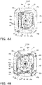
- FIG. 4A is a plan view from the air blow-in side, of the indoor unit 20 with a decorative panel 40 being separated.
- the indoor unit 20 is of a ceiling embedded type.
- the indoor unit 20 includes a body 21, and the decorative panel 40 attached to a bottom of the body 21.
- the body 21 includes a casing 22, the indoor heat exchanger 32, an indoor expansion valve 39, an indoor fan 30, and a gas sensor 55.
- the decorative panel 40 is attached to the bottom of the body 21.
- the decorative panel 40 includes a panel portion 41 and a suction grill 60.
- the panel portion 41 is provided with a single blow-in flow path 42 and four blow-out flow paths 43. As depicted in FIG. 2 , the blow-in flow path 42 is provided at a center of the panel portion 41.
- the body 21 and the blow-in flow path 42 interpose a blow-in port 42a.
- the blow-in flow path 42 in the panel portion 41 has a lower end provided with an opening 41a corresponding to the blow-in port 42a.
- the opening 41a has a quadrilateral shape in a planar view, and the suction grill 60 is attached to prevent an interior of the indoor unit 20 from being visible via the opening 41a.
- the opening 41a and the blow-in port 42a interpose a filter 45 configured to capture dust in air sucked via the opening 41a.
- the blow-out flow paths 43 are provided outside the blow-in flow path 42 to surround the blow-in flow path 42.
- the blow-out flow paths 43 respectively extend along four sides of the blow-in flow path 42.
- the body 21 and each of the blow-out flow paths 43 interpose a blow-out port 37a.
- the blow-out flow paths 43 in the panel portion 41 each have a lower end provided with an opening 43a corresponding to the blow-out port 37a.
- the casing 22 has a plurality of side walls, and has an octagonal shape obtained by alternately connecting four short sides and four long sides in a planar view.
- FIG. 4A depicts a first short side wall 22a as a side wall penetrated by the liquid connecting pipe 6 and the gas connecting pipe 7 connected to the indoor heat exchanger 32.
- the first short side wall 22a has a portion that is penetrated by the liquid connecting pipe 6 and the gas connecting pipe 7 and is bent to be perpendicular to the pipes.
- FIG. 4A depicts a first long side wall 22b, a second short side wall 22c, a second long side wall 22d, a third short side wall 22e, a third long side wall 22f, a fourth short side wall 22g, and a fourth long side wall 22h, which are disposed clockwise from the first short side wall 22a.
- FIG. 4B is a plan view from the blow-in port 42a, of the indoor unit 20 with a drain pan 36 being separated from a state of FIG. 4A .
- the plurality of side walls depicted in FIG. 4B forms a first corner 221, a second corner 222, a third corner 223, and a fourth corner 224 in the casing 22.
- the first corner 221 is formed by the first long side wall 22b and the fourth long side wall 22h, faces the first short side wall 22a, and an end part 32a of the indoor heat exchanger 32 is installed at the first corner 221.
- the end part of the indoor heat exchanger 32 is connected with the liquid connecting pipe 6 and the gas connecting pipe 7 that penetrate the first short side wall 22a as described above.
- the liquid connecting pipe 6 is connected with the liquid connection pipe 2 and the gas connecting pipe 7 is connected with the gas connection pipe 3.
- the casing 22 accommodates the indoor fan 30, a bell mouth 31, the indoor heat exchanger 32, and the drain pan 36.
- the indoor fan 30 is a centrifugal fan driven by an indoor fan motor 30a.
- An operating frequency of the indoor fan motor 30a is variable by means of an inverter device.
- the indoor fan 30 is disposed at a center in the casing 22.
- the indoor fan 30 includes the indoor fan motor 30a and an impeller 30b.
- the indoor fan motor 30a is supported by a top panel of the casing 22.
- the impeller 30b is constituted by a plurality of turbo wings arranged in a rotation direction of a drive shaft.
- the bell mouth 31 is disposed below the indoor fan 30.
- the bell mouth 31 has a circular opening at each of upper and lower ends, and has a tubular shape with an opening area gradually increased toward the decorative panel 40.
- the bell mouth 31 has an arc surface that smoothly connects from the upper end to the lower end and the portion forming the arc surface is called an arc plate 31a.
- the bell mouth 31 has an internal space communicating with an accommodation space of the indoor fan 30.
- the bell mouth 31 can thus guide air introduced from the opening 41a via the blow-in port 42a into the indoor unit 20.
- the indoor heat exchanger 32 is of a fin and tube type.
- the indoor heat exchanger 32 is installed adjacent to the indoor fan 30.
- the indoor heat exchanger 32 includes a heat transfer tube bent to surround the indoor fan 30.
- the indoor heat exchanger 32 is installed on an upper surface of the drain pan 36 to rise upward.
- the indoor heat exchanger 32 allows passage of air blown laterally from the indoor fan 30.
- the indoor heat exchanger 32 constitutes an evaporator configured to cool air during cooling operation, and constitutes a radiator configured to heat air during heating operation.
- the drain pan 36 is installed around the bell mouth 31.
- the indoor heat exchanger 32 is installed above the drain pan 36 that receives water condensed by the indoor heat exchanger 32 and falling downward.
- the drain pan 36 has a first surface 36a facing a bottom of the indoor heat exchanger 32, and a second surface 36b other than the first surface 36a.
- the indoor expansion valve 39 is connected to a liquid end part of the indoor heat exchanger 32 in the refrigerant circuit C.
- the indoor expansion valve 39 is constituted by an electronic expansion valve having a variable opening degree.
- the casing 22 accommodates an electric component box 50.
- the electric component box 50 is installed at a position visible by a user or a service person when the user or the service person shifts the suction grill 60.
- the electric component box 50 is installed along at least one of the first long side wall 22b and the fourth long side wall 22h forming the first corner 221 of the casing 22.
- the electric component box 50 accommodates a control board 501 that is also disposed along at least one of the first long side wall 22b and the fourth long side wall 22h forming the first corner 221 of the casing 22.
- the control board 501 is equipped with a microcomputer MC that is configured to determine whether or not a refrigerant is leaking in accordance with a signal inputted from the gas sensor 55 or the like.
- FIG. 5A is a perspective view of the gas sensor 55 to be covered with a case 56.
- FIG. 5B is a perspective view of the gas sensor 55 covered with the case 56.
- the gas sensor 55 depicted in FIG. 5A and FIG. 5B detects refrigerant leakage.
- the gas sensor 55 includes a substrate 551, a sensor unit 552, and a wiring unit 553.
- the sensor unit 552 includes a sensor element 552a, and a cylindrical pipe 552b covering the sensor element 552a.
- the sensor element 552a is mounted on the substrate 551 and detects whether or not there is refrigerant gas.
- the cylindrical pipe 552b has an upper end surface provided with a hole 552c allowing entry of refrigerant gas.
- the wiring unit 553 includes a female connector 553a mounted on the substrate 551, a male connector 553b inserted to the female connector 553a, and a cable 553c connected to the male connector 553b.
- the wiring unit 553 electrically connects the sensor element 552a and the control board 551.
- the case 56 has a first opening 561 for ventilation.
- the first opening 561 is provided in a surface called a ventilation surface 56a.
- the ventilation surface 56a crosses a side surface 56b provided with a second opening 562.
- part of refrigerant gas entered via the first opening 561 can flow to the sensor unit 552 of the gas sensor 55 and the remaining can exit via the second opening 562.
- part of refrigerant gas entered via the second opening 562 can flow to the sensor unit 552 of the gas sensor 55 and the remaining can exit via the first opening 561.
- the ventilation surface 56a has a plurality of first openings 561 and the side surface 56b has a plurality of second openings 562. There may alternatively be provided a single first opening 561 and a single second opening 562.
- the case 56 exerts two functions of protecting the sensor unit 552 and introducing refrigerant gas as a leaking refrigerant.
- the air conditioner 10 according to the present embodiment will be described next in terms of its operation.
- the air conditioner 10 switchingly executes cooling operation and heating operation.
- the four-way switching valve 15 depicted in FIG. 1 is in the state indicated by solid lines, and the compressor 12, the indoor fan 30, and the outdoor fan 16 are in an operating state.
- the refrigerant circuit C thus achieves a refrigeration cycle in which the outdoor heat exchanger 13 functions as a radiator and the indoor heat exchanger 32 functions as an evaporator.
- a high pressure refrigerant compressed by the compressor 12 flows in the outdoor heat exchanger 13 to exchange heat with outdoor air.
- the high pressure refrigerant radiates heat to the outdoor air in the outdoor heat exchanger 13.
- a refrigerant condensed by the outdoor heat exchanger 13 is sent to the indoor unit 20.
- the refrigerant in the indoor unit 20 is decompressed by the indoor expansion valve 39 and then flows in the indoor heat exchanger 32.
- indoor air blown out of the indoor fan 30 passes the indoor heat exchanger 32 to exchange heat with the refrigerant.
- the refrigerant in the indoor heat exchanger 32 is evaporated by absorbing heat from the indoor air.
- the indoor air is cooled by the refrigerant.
- the air cooled by the indoor heat exchanger 32 is supplied into an indoor space.
- the refrigerant evaporated in the indoor heat exchanger 32 is sucked into the compressor 12 to be compressed again.
- the four-way switching valve 15 depicted in FIG. 1 is in the state indicated by broken lines, and the compressor 12, the indoor fan 30, and the outdoor fan 16 are in the operating state.
- the refrigerant circuit C thus achieves a refrigeration cycle in which the indoor heat exchanger 32 functions as a condenser and the outdoor heat exchanger 13 functions as an evaporator.
- a high pressure refrigerant compressed by the compressor 12 flows in the indoor heat exchanger 32 of the indoor unit 20.
- indoor air blown out of the indoor fan 30 passes the indoor heat exchanger 32 to exchange heat with the refrigerant.
- the refrigerant in the indoor heat exchanger 32 is condensed by radiating heat to the indoor air.
- the indoor air is heated by the refrigerant.
- the air heated in the indoor heat exchanger 32 is supplied into the indoor space.
- the refrigerant condensed in the indoor heat exchanger 32 is decompressed by the outdoor expansion valve 14 and then flows in the outdoor heat exchanger 13.
- the refrigerant in the outdoor heat exchanger 13 absorbs heat from outdoor air to be evaporated.
- the refrigerant evaporated in the outdoor heat exchanger 13 is sucked into the compressor 12 to be compressed again.
- the gas sensor 55 is accommodated in the casing 22, but is positioned to be ejectable when the suction grill 60 is shifted. Specifically, the gas sensor 55 is installed at the second surface 36b of the drain pan 36 so as to be adjacent to the electric component box 50.
- the second surface 36b of the drain pan 36 corresponds to the surface excluding the first surface 36a facing the bottom of the indoor heat exchanger 32.
- the second surface 36b is desirably displaced along the blow-in port 42a.
- the present embodiment provides a flat plate 31b disposed adjacent to a lower end of the arc plate 31a of the bell mouth 31 so as to surround the lower end.
- the flat plate 31b is positioned below a bottom wall of the drain pan 36.
- the bottom wall of the drain pan 36 has a step 361 to be in contact with the flat plate 31b.
- the step 361 ( FIG. 1 ) includes a horizontal plane 361a in contact with an end part of the flat plate 31b, and a vertical plane 361b standing vertically downward from a terminal end of the horizontal plane 361a.
- the gas sensor 55 is positioned adjacent to the electric component box 50 as depicted in FIG. 3 , and is attached onto the flat plate 31b in a posture such that the hole 552c of the cylindrical pipe 552b in the sensor unit 552 depicted in FIG. 5A is directed vertically downward.
- FIG. 5C is an enlarged plan view of a location of the gas sensor 55.
- FIG. 5D is a side view, along arrow A indicated in FIG. 5C , of the gas sensor 55.
- the ventilation surface 56a of the case 56 faces the suction grill 60 and is disposed along an opening plane of the blow-in port 42a.
- the cable 553c of the wiring unit 553 is curved to be positioned below the sensor unit 552 and is then introduced into the electric component box 50. This configuration prevents any waterdrop adhering to the cable from permeating the substrate 551 along the cable 553c.
- the refrigerant gas is blocked by the filter 45 to fill a space between the flat plate 31b and the filter 45.
- the refrigerant gas flows from the ventilation surface 56a of the case 56, reaches the sensor unit 552 via the first openings 561, and enters the cylindrical pipe 552b via the hole 552c of the cylindrical pipe 552b to come into contact with the sensor element 552a.
- the sensor element 552a outputs different voltage values before and after the refrigerant gas comes into contact with the sensor element 552a.
- the microcomputer MC accordingly determines that refrigerant leakage has occurred in accordance with change in signal voltage inputted to the control board 501 via the wiring unit 553.
- the electric component box 50 and the gas sensor 55 are installed below the bell mouth 31 and above the filter 45. As depicted in FIG. 2 and FIG. 3 , the electric component box 50 and the gas sensor 55 are disposed within a lateral width of the opening 41a. When a user or a service person detaches the suction grill 60 from the opening 41a and further detaches the filter 45, the electric component box 50 and the gas sensor 55 are thus positioned to be visible by the user or the service person and be reached by a hand of the user or the service person.
- the gas sensor 55 according to the present embodiment is attached at a position facilitating attachment of the gas sensor 55 with excellent maintainability.
- the gas sensor 55 configured to detect refrigerant leakage is positioned to be ejectable when the suction grill 60 is shifted. A user or a service person can thus easily attach and detach the gas sensor 55 with excellent maintainability.
- the drain pan 36 has the first surface 36a facing the bottom of the indoor heat exchanger 32 and the second surface 36b other than the first surface 36a, and the gas sensor 55 is installed at the second surface 36b.
- the drain pan 36 is installed around the bell mouth 31.
- the end part 32a of the indoor heat exchanger 32 is disposed at the first corner 221 among the plurality of corners of the casing 22, and the electric component box 50 is installed along at least one of the first long side wall 22b and the fourth long side wall 22h forming the first corner 221.
- the filter 45 is installed between the blow-in port 42a and the suction grill 60.
- the gas sensor 55 is exposed when the filter 45 is detached, and a user or a service person can thus easily attach and detach the gas sensor 55 with excellent maintainability.
- a plurality of gas sensors 55 is installed at or adjacent to the electric component box 50.
- the gas sensor 55 is covered with the case 56 having the first openings 561 for ventilation, and the case 56 exerts two functions of protecting the sensor unit 552 and introducing refrigerant gas as a leaking refrigerant.
- the ventilation surface 56a of the case 56 is provided with the first openings 561.
- the ventilation surface 56a faces the suction grill 60.
- the side surface 56b of the case 56 is provided with the second openings 562.
- part of refrigerant gas entered via the first openings 561 can flow to the sensor unit 552 of the gas sensor 55 and the remaining can exit via the second openings 562.
- part of refrigerant gas entered via the second openings 562 can flow to the sensor unit 552 of the gas sensor 55 and the remaining can exit via the first openings 561.
- the indoor unit 20 may further include a plurality of gas sensors 55 that is installed at a plurality of different positions.
- FIG. 6 is a perspective view from below, of the indoor unit 20 according to the first modification example, with the decorative panel 40 being detached, depicting locations of the plurality of gas sensors 55 being installed.
- FIG. 6 depicts three gas sensors 55 being installed.
- the three gas sensors 55 include a first gas sensor 55A, a second gas sensor 55B, and a third gas sensor 55C.
- the first gas sensor 55A is installed at the second surface 36b of the drain pan 36, at a position adjacent to the electric component box 50 and also adjacent to the end part 32a of the indoor heat exchanger 32.
- the second gas sensor 55B is installed at a center of the surface, facing the suction grill 60, of the electric component box 50.
- the third gas sensor 55C is installed at the second surface 36b of the drain pan 36, at a position adjacent to the electric component box 50 and farther than the first gas sensor 55A from the end part 32a of the indoor heat exchanger 32.
- a refrigerant leaking from the indoor heat exchanger 32 accumulates at the drain pan 36, and refrigerant gas as a leaking refrigerant overflown therefrom flows beyond the bell mouth 31 and out of the blow-in port 42a to spread to a border between the body 21 and the decorative panel 40.
- the gas sensor 55 is thus ideally installed to surround the arc plate 31a of the bell mouth 31.
- the plurality of gas sensors 55 is desirably installed at or adjacent to the electric component box 50 as described above.
- the above first modification example exemplifies the locations of the plurality of gas sensors 55, though there is no need to simultaneously use all the gas sensors 55 thus installed.
- only the first gas sensor 55A may be used initially and the second gas sensor 55B may be switchingly used before the first gas sensor 55A terminates its durability life cycle.
- the first gas sensor 55A can be switched at timing that can be exemplarily determined in accordance with guarantee years of the gas sensor 55A.
- the first gas sensor 55A may alternatively be switched to a subsequent gas sensor 55 when abnormality different from refrigerant leakage is assumed in accordance with an output signal of the first gas sensor 55A.
- the second gas sensor 55B and the third gas sensor 55C may be used in this order.
- FIG. 6B is a perspective view from below, of the indoor unit 20 according to the third modification example, with the decorative panel 40 being detached, depicting locations of the first gas sensor 55A and the second gas sensor 55B.
- the first gas sensor 55A and the second gas sensor 55B depicted in FIG. 6B are installed vertically.
- examples of a method of use include a first aspect of connecting each of the first gas sensor 55A and the second gas sensor 55B to the control board 501, and a second aspect of connecting only one of the gas sensors.
- any gas sensor not detecting refrigerant leakage after elapse of the predetermined period can thus be determined as being abnormal.
- only the first gas sensor 55A in the first gas sensor 55A and the second gas sensor 55B is exemplarily connected to the control board 501 to be in use, whereas the remaining gas sensor is not in use.
- the first gas sensor 55A When the first gas sensor 55A is in trouble, a user or a service person has only to connect, in place of the first gas sensor 55A, the second gas sensor 55B stored below the first gas sensor 55A to the control board 501 to complete replacement of the gas sensor.
- the user or the service person can thus replace the gas sensor even when visiting for repair without carrying any gas sensor for replacement.
- the embodiment and the modification examples described above exemplify the case where installation conditions of the gas sensor 55 are applied to an indoor unit of a ceiling embedded type for full blowoff.
- the installation conditions are exemplarily applicable also to an indoor unit of the ceiling embedded type for four-way blowoff, and an indoor unit of the ceiling embedded type for two-way blowoff.
- the embodiment and the modification examples described above have no limitation in terms of a refrigerant enclosed in the refrigerant circuit C. All refrigerants, irrespective of incombustible refrigerants or combustible refrigerants, can be adopted. In view of safety, the embodiment and the modification examples described above are useful to combustible refrigerants.
- Examples of the combustible refrigerant include refrigerants categorized in Class 3 (higher flammability), Class 2 (lower flammability), and Subclass 2L (slight flammability) in the standards according to ASHRAE 34 Designation and safety classification of refrigerant in the U.S.A. or the standards according to ISO 817 Refrigerants - Designation and safety classification.
- Exemplarily adopted as the combustible refrigerant is any one of R1234yf, R1234ze(E), R516A, R445A, R444A, R454C, R444B, R454A, R455A, R457A, R459B, R452B, R454B, R447B, R32, R447A, R446A, and R459A.
- the embodiment and the modification examples described above refer to the air conditioner as an exemplary refrigeration apparatus.
- the refrigeration apparatus include, as well as the air conditioner, a low temperature warehouse storing articles that need to be frozen, refrigerated, or kept at low temperature.
- the ventilation surface 56a facing the suction grill 60 is provided with the first openings 561, and the side surface 56b crossing the ventilation surface 56a is provided with the second openings 562.
- the first openings 561 and the second openings 562 are disposed in a mode that should not be limited to the above.
- the ventilation surface 56a is provided with the plurality of first openings 561, part of which may serve as a refrigerant gas inflow port and the remaining may serve as a refrigerant gas outflow port.
- the second openings 562 in the side surface 56b can be eliminated in this case.
- Patent Literature 1 JP 2019-11914 A
Landscapes
- Engineering & Computer Science (AREA)
- Mechanical Engineering (AREA)
- General Engineering & Computer Science (AREA)
- Chemical & Material Sciences (AREA)
- Combustion & Propulsion (AREA)
- Physics & Mathematics (AREA)
- Thermal Sciences (AREA)
- Air Conditioning Control Device (AREA)
- Air Filters, Heat-Exchange Apparatuses, And Housings Of Air-Conditioning Units (AREA)
- Devices For Blowing Cold Air, Devices For Blowing Warm Air, And Means For Preventing Water Condensation In Air Conditioning Units (AREA)
Abstract
Description
- The present disclosure relates to an indoor unit of a refrigeration apparatus configured to detect refrigerant leakage.
- In recent years, air conditioners adopting refrigerants having low global warming potential (GWP) (hereinafter, called low GWP refrigerants) in view of environmental protection. Examples of the low GWP refrigerants include a refrigerant disclosed in Patent Literature 1 (
JP 2019-11914 A - It is necessary to install a gas sensor for future refrigerant leakage. When the gas sensor has abnormality, a user or a service person repairs or replaces the gas sensor.
- In an indoor unit of a conventional air conditioner including a gas sensor, in view of whether or not a user or a service person can easily attach and detach the gas sensor, a location of the gas sensor is not regarded as being selected to facilitate attachment and detachment.
- There is accordingly an object of selecting the location of the gas sensor that can be easily attached and detached by the user or the service person.
- An indoor unit of a refrigeration apparatus according to a first aspect is to be installed at a ceiling, and includes a casing and a plate-shaped member. The casing has a plurality of blow-out ports and a blow-in port provided in a lower surface. The plate-shaped member is installed below the blow-in port. The casing accommodates a heat exchanger, a control board, a support member, and a gas sensor. The heat exchanger allows a refrigerant larger in specific gravity than air to flow therein. The support member supports the control board. The gas sensor is installed at or adjacent to the support member, and detects refrigerant leakage. The gas sensor is ejectable when the plate-shaped member is shifted.
- A user or a service person can attach and detach the gas sensor by shifting the plate-shaped member, so that the indoor unit provides excellent maintainability.
- An indoor unit of a refrigeration apparatus according to a second aspect is the indoor unit of the refrigeration apparatus according to the first aspect, and the indoor unit further includes a drain pan installed below the heat exchanger. The drain pan has a first surface facing a bottom of the heat exchanger, and a second surface other than the first surface. The gas sensor is installed at the second surface.
- An indoor unit of a refrigeration apparatus according to a third aspect is the indoor unit of the refrigeration apparatus according to the second aspect, and the indoor unit further includes a bell mouth configured to guide air introduced via the blow-in port. The drain pan is installed around the bell mouth.
- An indoor unit of a refrigeration apparatus according to a fourth aspect is the indoor unit of the refrigeration apparatus according to any one of the first to third aspects, in which the casing has a plurality of side walls. The plurality of side walls forms a plurality of corners. The plurality of corners includes a first corner that an end part of the heat exchanger is installed. The support member is disposed along at least one of two side walls forming the first corner of the casing.
- An indoor unit of a refrigeration apparatus according to a fifth aspect is the indoor unit of the refrigeration apparatus according to any one of the first to fourth aspects, and the indoor unit further includes a filter installed between the blow-in port and the plate-shaped member.
- A user or a service person can attach and detach the gas sensor exposed when the filter is detached, so that the indoor unit provides excellent maintainability.
- An indoor unit of a refrigeration apparatus according to a sixth aspect is the indoor unit of the refrigeration apparatus according to any one of the first to fifth aspects, and the indoor unit further includes a plurality of gas sensors. The plurality of gas sensors are installed at or adjacent to the support member.
- An indoor unit of a refrigeration apparatus according to a seventh aspect is the indoor unit of the refrigeration apparatus according to any one of the first to sixth aspects, in which the gas sensor is covered with a case having a first opening for ventilation.
- The case in the indoor unit can exert two functions of protecting the gas sensor and introducing refrigerant gas as a leaking refrigerant.
- An indoor unit of a refrigeration apparatus according to an eighth aspect is the indoor unit of the refrigeration apparatus according to the seventh aspect, in which the case has a ventilation surface facing the plate-shaped member. The ventilation surface is provided with the first opening.
- An indoor unit of a refrigeration apparatus according to a ninth aspect is the indoor unit of the refrigeration apparatus according to the seventh or eighth aspect, in which the case has a side surface provided with a second opening.
- When the indoor unit has refrigerant leakage, part of refrigerant gas entered via the first opening can flow to a
gas sensor 55 and the remaining can exit via the second opening. Alternatively, part of refrigerant gas entered via the second opening can flow to thegas sensor 55 and the remaining can exit via the first opening. -
-
FIG. 1 is a piping diagram depicting a configuration of a refrigerant circuit in an air conditioner according to an embodiment of the present disclosure. -
FIG. 2 is a longitudinal sectional view of an indoor unit of the air conditioner. -
FIG. 3 is a perspective view from an air blow-in side, of the indoor unit with a decorative panel being separated. -
FIG. 4A is a plan view from the air blow-in side, of the indoor unit with the decorative panel being separated. -
FIG. 4B is a plan view from a blow-in port, of the indoor unit with the decorative panel and a drain pan being separated. -
FIG. 5A is a perspective view of a gas sensor to be covered with a case. -
FIG. 5B is a perspective view of the gas sensor covered with the case. -
FIG. 5C is an enlarged plan view of a location of the gas sensor. -
FIG. 5D is a side view, along arrow A indicated inFIG. 5C , of the gas sensor. -
FIG. 6A is a perspective view from below, of an indoor unit according to a first modification example, with a decorative panel being detached. -
FIG. 6B is a partial enlarged perspective view from below, of an indoor unit according to a third modification example, with a decorative panel being detached. - Description is made herein to an air conditioner 10 as an exemplary refrigeration apparatus.
-
FIG. 1 is a piping diagram depicting a configuration of a refrigerant circuit C in the air conditioner 10 according to an embodiment of the present disclosure. The air conditioner 10 depicted inFIG. 1 cools and heats air in a room. As depicted inFIG. 1 , the air conditioner 10 includes anoutdoor unit 11 disposed outdoors and anindoor unit 20 installed in the room. Theoutdoor unit 11 and theindoor unit 20 are connected to each other by twoconnection pipes - The
outdoor unit 11 is provided with acompressor 12, anoutdoor heat exchanger 13, anoutdoor expansion valve 14, and a four-way switching valve 15. - The
compressor 12 compresses a low-pressure refrigerant and discharges a highpressure refrigerant obtained by compression. Thecompressor 12 includes a compression mechanism of a scroll type, a rotary type, or the like driven by acompressor motor 12a. Thecompressor motor 12a has an operating frequency variable by means of an inverter device. - As depicted in
FIG. 1 , there is provided adischarge pipe 121 connecting a refrigerant discharge port of thecompressor 12 and the four-way switching valve 15. There is further provided asuction pipe 122 connecting a suction port of thecompressor 12 and the four-way switching valve 15. - The
outdoor heat exchanger 13 is of a fin and tube type. There is installed anoutdoor fan 16 adjacent to theoutdoor heat exchanger 13. Theoutdoor heat exchanger 13 causes heat exchange between air conveyed by theoutdoor fan 16 and a refrigerant flowing in theoutdoor heat exchanger 13. - As depicted in
FIG. 1 , there is provided afirst pipe 131 connecting a refrigerant inflow port of theoutdoor heat exchanger 13 and the four-way switching valve 15 during cooling operation. - The
outdoor expansion valve 14 is an electronic expansion valve having a variable opening degree. Theoutdoor expansion valve 14 is installed downstream of theoutdoor heat exchanger 13 in a refrigerant flow direction in the refrigerant circuit C during cooling operation. - The opening degree of the
outdoor expansion valve 14 is fully opened during cooling operation. In contrast, during heating operation, the opening degree of theoutdoor expansion valve 14 is adjusted such that a refrigerant flowing into theoutdoor heat exchanger 13 is decompressed to pressure enabling evaporation (evaporation pressure) in theoutdoor heat exchanger 13. - The four-
way switching valve 15 has first to fourth ports. At the four-way switching valve 15, a first port P1 is connected to thedischarge pipe 121 of thecompressor 12, a second port P2 is connected to thesuction pipe 122 of thecompressor 12, a third port P3 is connected to thefirst pipe 131 of theoutdoor heat exchanger 13, and a fourth port P4 is connected to agas shutoff valve 5. - The four-
way switching valve 15 is switched between a first state (state indicated by solid lines inFIG. 1 ) and a second state (state indicated by broken lines inFIG. 1 ). At the four-way switching valve 15 in the first state, the first port P1 and the third port P3 communicate with each other and the second port P2 and the fourth port P4 communicate with each other. At the four-way switching valve 15 in the second state, the first port P1 and the fourth port P4 communicate with each other and the second port P2 and the third port P3 communicate with each other. - The
outdoor fan 16 is constituted as a propeller fan driven by anoutdoor fan motor 16a. An operating frequency of theoutdoor fan motor 16a is variable by means of an inverter device. - The two connection pipes include the
liquid connection pipe 2 and thegas connection pipe 3. Theliquid connection pipe 2 has a first end connected to aliquid shutoff valve 4 and a second end connected to aliquid connecting pipe 6 of anindoor heat exchanger 32. As depicted inFIG. 1 , theliquid connecting pipe 6 is connected directly or indirectly to a refrigerant inlet of theindoor heat exchanger 32 during cooling operation. - The
gas connection pipe 3 has a first end connected to thegas shutoff valve 5 and a second end connected to agas connecting pipe 7 of theindoor heat exchanger 32. As depicted inFIG. 1 , thegas connecting pipe 7 is connected directly or indirectly to a refrigerant outlet of theindoor heat exchanger 32 during cooling operation. -
FIG. 2 is a longitudinal sectional view of theindoor unit 20 of the air conditioner 10.FIG. 3 is a perspective view from an air blow-in side, of theindoor unit 20 with a decorative panel being separated.FIG. 4A is a plan view from the air blow-in side, of theindoor unit 20 with adecorative panel 40 being separated. - In
FIG. 2 ,FIG. 3 , andFIG. 4A , theindoor unit 20 according to the present embodiment is of a ceiling embedded type. Theindoor unit 20 includes abody 21, and thedecorative panel 40 attached to a bottom of thebody 21. - As depicted in
FIG. 2 andFIG. 3 , thebody 21 includes acasing 22, theindoor heat exchanger 32, an indoor expansion valve 39, anindoor fan 30, and agas sensor 55. - The
decorative panel 40 is attached to the bottom of thebody 21. Thedecorative panel 40 includes apanel portion 41 and asuction grill 60. - The
panel portion 41 is provided with a single blow-inflow path 42 and four blow-outflow paths 43. As depicted inFIG. 2 , the blow-inflow path 42 is provided at a center of thepanel portion 41. Thebody 21 and the blow-inflow path 42 interpose a blow-inport 42a. The blow-inflow path 42 in thepanel portion 41 has a lower end provided with anopening 41a corresponding to the blow-inport 42a. - The
opening 41a has a quadrilateral shape in a planar view, and thesuction grill 60 is attached to prevent an interior of theindoor unit 20 from being visible via theopening 41a. - The
opening 41a and the blow-inport 42a interpose afilter 45 configured to capture dust in air sucked via theopening 41a. - The blow-out
flow paths 43 are provided outside the blow-inflow path 42 to surround the blow-inflow path 42. The blow-outflow paths 43 respectively extend along four sides of the blow-inflow path 42. Thebody 21 and each of the blow-outflow paths 43 interpose a blow-outport 37a. The blow-outflow paths 43 in thepanel portion 41 each have a lower end provided with anopening 43a corresponding to the blow-outport 37a. - The
casing 22 has a plurality of side walls, and has an octagonal shape obtained by alternately connecting four short sides and four long sides in a planar view.FIG. 4A depicts a firstshort side wall 22a as a side wall penetrated by theliquid connecting pipe 6 and thegas connecting pipe 7 connected to theindoor heat exchanger 32. The firstshort side wall 22a has a portion that is penetrated by theliquid connecting pipe 6 and thegas connecting pipe 7 and is bent to be perpendicular to the pipes. -
FIG. 4A depicts a firstlong side wall 22b, a secondshort side wall 22c, a secondlong side wall 22d, a thirdshort side wall 22e, a thirdlong side wall 22f, a fourthshort side wall 22g, and a fourthlong side wall 22h, which are disposed clockwise from the firstshort side wall 22a. -
FIG. 4B is a plan view from the blow-inport 42a, of theindoor unit 20 with adrain pan 36 being separated from a state ofFIG. 4A . The plurality of side walls depicted inFIG. 4B forms afirst corner 221, asecond corner 222, athird corner 223, and afourth corner 224 in thecasing 22. - The
first corner 221 is formed by the firstlong side wall 22b and the fourthlong side wall 22h, faces the firstshort side wall 22a, and anend part 32a of theindoor heat exchanger 32 is installed at thefirst corner 221. - The end part of the
indoor heat exchanger 32 is connected with theliquid connecting pipe 6 and thegas connecting pipe 7 that penetrate the firstshort side wall 22a as described above. Theliquid connecting pipe 6 is connected with theliquid connection pipe 2 and thegas connecting pipe 7 is connected with thegas connection pipe 3. - The
casing 22 accommodates theindoor fan 30, abell mouth 31, theindoor heat exchanger 32, and thedrain pan 36. - The
indoor fan 30 is a centrifugal fan driven by anindoor fan motor 30a. An operating frequency of theindoor fan motor 30a is variable by means of an inverter device. - As depicted in
FIG. 3 ,FIG. 4A, and FIG. 4B , theindoor fan 30 is disposed at a center in thecasing 22. Theindoor fan 30 includes theindoor fan motor 30a and animpeller 30b. Theindoor fan motor 30a is supported by a top panel of thecasing 22. Theimpeller 30b is constituted by a plurality of turbo wings arranged in a rotation direction of a drive shaft. - The
bell mouth 31 is disposed below theindoor fan 30. Thebell mouth 31 has a circular opening at each of upper and lower ends, and has a tubular shape with an opening area gradually increased toward thedecorative panel 40. Thebell mouth 31 has an arc surface that smoothly connects from the upper end to the lower end and the portion forming the arc surface is called anarc plate 31a. - The
bell mouth 31 has an internal space communicating with an accommodation space of theindoor fan 30. Thebell mouth 31 can thus guide air introduced from theopening 41a via the blow-inport 42a into theindoor unit 20. - The
indoor heat exchanger 32 is of a fin and tube type. Theindoor heat exchanger 32 is installed adjacent to theindoor fan 30. As depicted inFIG. 4A and FIG. 4B , theindoor heat exchanger 32 includes a heat transfer tube bent to surround theindoor fan 30. - The
indoor heat exchanger 32 is installed on an upper surface of thedrain pan 36 to rise upward. Theindoor heat exchanger 32 allows passage of air blown laterally from theindoor fan 30. Theindoor heat exchanger 32 constitutes an evaporator configured to cool air during cooling operation, and constitutes a radiator configured to heat air during heating operation. - The
drain pan 36 is installed around thebell mouth 31. Theindoor heat exchanger 32 is installed above thedrain pan 36 that receives water condensed by theindoor heat exchanger 32 and falling downward. Thedrain pan 36 has afirst surface 36a facing a bottom of theindoor heat exchanger 32, and asecond surface 36b other than thefirst surface 36a. - The indoor expansion valve 39 is connected to a liquid end part of the
indoor heat exchanger 32 in the refrigerant circuit C. The indoor expansion valve 39 is constituted by an electronic expansion valve having a variable opening degree. - The
casing 22 accommodates anelectric component box 50. Theelectric component box 50 is installed at a position visible by a user or a service person when the user or the service person shifts thesuction grill 60. - Specifically, the
electric component box 50 is installed along at least one of the firstlong side wall 22b and the fourthlong side wall 22h forming thefirst corner 221 of thecasing 22. - The
electric component box 50 accommodates acontrol board 501 that is also disposed along at least one of the firstlong side wall 22b and the fourthlong side wall 22h forming thefirst corner 221 of thecasing 22. - The
control board 501 is equipped with a microcomputer MC that is configured to determine whether or not a refrigerant is leaking in accordance with a signal inputted from thegas sensor 55 or the like. -
FIG. 5A is a perspective view of thegas sensor 55 to be covered with acase 56.FIG. 5B is a perspective view of thegas sensor 55 covered with thecase 56. Thegas sensor 55 depicted inFIG. 5A and FIG. 5B detects refrigerant leakage. Thegas sensor 55 includes asubstrate 551, asensor unit 552, and awiring unit 553. Thesensor unit 552 includes asensor element 552a, and acylindrical pipe 552b covering thesensor element 552a. - The
sensor element 552a is mounted on thesubstrate 551 and detects whether or not there is refrigerant gas. Thecylindrical pipe 552b has an upper end surface provided with ahole 552c allowing entry of refrigerant gas. - The
wiring unit 553 includes afemale connector 553a mounted on thesubstrate 551, amale connector 553b inserted to thefemale connector 553a, and acable 553c connected to themale connector 553b. Thewiring unit 553 electrically connects thesensor element 552a and thecontrol board 551. - At least the
sensor unit 552 of thegas sensor 55 is covered with theprotective case 56. Thecase 56 has afirst opening 561 for ventilation. Thefirst opening 561 is provided in a surface called aventilation surface 56a. - The
ventilation surface 56a according to the present embodiment crosses aside surface 56b provided with asecond opening 562. - When a refrigerant leaks, part of refrigerant gas entered via the
first opening 561 can flow to thesensor unit 552 of thegas sensor 55 and the remaining can exit via thesecond opening 562. Alternatively, when the refrigerant leaks, part of refrigerant gas entered via thesecond opening 562 can flow to thesensor unit 552 of thegas sensor 55 and the remaining can exit via thefirst opening 561. - According to the present embodiment, the
ventilation surface 56a has a plurality offirst openings 561 and theside surface 56b has a plurality ofsecond openings 562. There may alternatively be provided a singlefirst opening 561 and a singlesecond opening 562. - The
case 56 exerts two functions of protecting thesensor unit 552 and introducing refrigerant gas as a leaking refrigerant. - The air conditioner 10 according to the present embodiment will be described next in terms of its operation. The air conditioner 10 switchingly executes cooling operation and heating operation.
- During cooling operation, the four-
way switching valve 15 depicted inFIG. 1 is in the state indicated by solid lines, and thecompressor 12, theindoor fan 30, and theoutdoor fan 16 are in an operating state. The refrigerant circuit C thus achieves a refrigeration cycle in which theoutdoor heat exchanger 13 functions as a radiator and theindoor heat exchanger 32 functions as an evaporator. - Specifically, a high pressure refrigerant compressed by the
compressor 12 flows in theoutdoor heat exchanger 13 to exchange heat with outdoor air. The high pressure refrigerant radiates heat to the outdoor air in theoutdoor heat exchanger 13. A refrigerant condensed by theoutdoor heat exchanger 13 is sent to theindoor unit 20. The refrigerant in theindoor unit 20 is decompressed by the indoor expansion valve 39 and then flows in theindoor heat exchanger 32. - In the
indoor unit 20, indoor air blown out of theindoor fan 30 passes theindoor heat exchanger 32 to exchange heat with the refrigerant. The refrigerant in theindoor heat exchanger 32 is evaporated by absorbing heat from the indoor air. The indoor air is cooled by the refrigerant. - The air cooled by the
indoor heat exchanger 32 is supplied into an indoor space. The refrigerant evaporated in theindoor heat exchanger 32 is sucked into thecompressor 12 to be compressed again. - During heating operation, the four-
way switching valve 15 depicted inFIG. 1 is in the state indicated by broken lines, and thecompressor 12, theindoor fan 30, and theoutdoor fan 16 are in the operating state. The refrigerant circuit C thus achieves a refrigeration cycle in which theindoor heat exchanger 32 functions as a condenser and theoutdoor heat exchanger 13 functions as an evaporator. - Specifically, a high pressure refrigerant compressed by the
compressor 12 flows in theindoor heat exchanger 32 of theindoor unit 20. In theindoor unit 20, indoor air blown out of theindoor fan 30 passes theindoor heat exchanger 32 to exchange heat with the refrigerant. The refrigerant in theindoor heat exchanger 32 is condensed by radiating heat to the indoor air. The indoor air is heated by the refrigerant. - The air heated in the
indoor heat exchanger 32 is supplied into the indoor space. The refrigerant condensed in theindoor heat exchanger 32 is decompressed by theoutdoor expansion valve 14 and then flows in theoutdoor heat exchanger 13. The refrigerant in theoutdoor heat exchanger 13 absorbs heat from outdoor air to be evaporated. The refrigerant evaporated in theoutdoor heat exchanger 13 is sucked into thecompressor 12 to be compressed again. - The
gas sensor 55 is accommodated in thecasing 22, but is positioned to be ejectable when thesuction grill 60 is shifted. Specifically, thegas sensor 55 is installed at thesecond surface 36b of thedrain pan 36 so as to be adjacent to theelectric component box 50. - The
second surface 36b of thedrain pan 36 corresponds to the surface excluding thefirst surface 36a facing the bottom of theindoor heat exchanger 32. In view of maintainability for replacement of thegas sensor 55, thesecond surface 36b is desirably displaced along the blow-inport 42a. - The present embodiment provides a
flat plate 31b disposed adjacent to a lower end of thearc plate 31a of thebell mouth 31 so as to surround the lower end. Theflat plate 31b is positioned below a bottom wall of thedrain pan 36. In order to avoid interference between theflat plate 31b and the bottom wall of thedrain pan 36, the bottom wall of thedrain pan 36 has astep 361 to be in contact with theflat plate 31b. - The step 361 (
FIG. 1 ) includes ahorizontal plane 361a in contact with an end part of theflat plate 31b, and avertical plane 361b standing vertically downward from a terminal end of thehorizontal plane 361a. - The
gas sensor 55 is positioned adjacent to theelectric component box 50 as depicted inFIG. 3 , and is attached onto theflat plate 31b in a posture such that thehole 552c of thecylindrical pipe 552b in thesensor unit 552 depicted inFIG. 5A is directed vertically downward. -
FIG. 5C is an enlarged plan view of a location of thegas sensor 55.FIG. 5D is a side view, along arrow A indicated inFIG. 5C , of thegas sensor 55. InFIG. 5C and FIG. 5D , theventilation surface 56a of thecase 56 faces thesuction grill 60 and is disposed along an opening plane of the blow-inport 42a. - As depicted in
FIG. 5D , thecable 553c of thewiring unit 553 is curved to be positioned below thesensor unit 552 and is then introduced into theelectric component box 50. This configuration prevents any waterdrop adhering to the cable from permeating thesubstrate 551 along thecable 553c. - Most of a refrigerant leaking from the
indoor heat exchanger 32 accumulates at thedrain pan 36, and refrigerant gas as a leaking refrigerant overflown therefrom flows beyond thebell mouth 31 and out of the blow-inport 42a to spread to a border between thebody 21 and thedecorative panel 40. - The refrigerant gas is blocked by the
filter 45 to fill a space between theflat plate 31b and thefilter 45. At thegas sensor 55, the refrigerant gas flows from theventilation surface 56a of thecase 56, reaches thesensor unit 552 via thefirst openings 561, and enters thecylindrical pipe 552b via thehole 552c of thecylindrical pipe 552b to come into contact with thesensor element 552a. - The
sensor element 552a outputs different voltage values before and after the refrigerant gas comes into contact with thesensor element 552a. The microcomputer MC accordingly determines that refrigerant leakage has occurred in accordance with change in signal voltage inputted to thecontrol board 501 via thewiring unit 553. - As depicted in
FIG. 2 ,FIG. 3 ,FIG. 4A, and FIG. 4B , theelectric component box 50 and thegas sensor 55 are installed below thebell mouth 31 and above thefilter 45. As depicted inFIG. 2 andFIG. 3 , theelectric component box 50 and thegas sensor 55 are disposed within a lateral width of theopening 41a. When a user or a service person detaches thesuction grill 60 from theopening 41a and further detaches thefilter 45, theelectric component box 50 and thegas sensor 55 are thus positioned to be visible by the user or the service person and be reached by a hand of the user or the service person. - As described above, the
gas sensor 55 according to the present embodiment is attached at a position facilitating attachment of thegas sensor 55 with excellent maintainability. - In the
indoor unit 20 of the air conditioner 10, thegas sensor 55 configured to detect refrigerant leakage is positioned to be ejectable when thesuction grill 60 is shifted. A user or a service person can thus easily attach and detach thegas sensor 55 with excellent maintainability. - In the
indoor unit 20 of the air conditioner 10, thedrain pan 36 has thefirst surface 36a facing the bottom of theindoor heat exchanger 32 and thesecond surface 36b other than thefirst surface 36a, and thegas sensor 55 is installed at thesecond surface 36b. - In the
indoor unit 20 of the air conditioner 10, thedrain pan 36 is installed around thebell mouth 31. - In the
indoor unit 20 of the air conditioner 10, theend part 32a of theindoor heat exchanger 32 is disposed at thefirst corner 221 among the plurality of corners of thecasing 22, and theelectric component box 50 is installed along at least one of the firstlong side wall 22b and the fourthlong side wall 22h forming thefirst corner 221. - In the
indoor unit 20 of the air conditioner 10, thefilter 45 is installed between the blow-inport 42a and thesuction grill 60. Thegas sensor 55 is exposed when thefilter 45 is detached, and a user or a service person can thus easily attach and detach thegas sensor 55 with excellent maintainability. - In the
indoor unit 20 of the air conditioner 10, a plurality ofgas sensors 55 is installed at or adjacent to theelectric component box 50. - In the
indoor unit 20 of the air conditioner 10, thegas sensor 55 is covered with thecase 56 having thefirst openings 561 for ventilation, and thecase 56 exerts two functions of protecting thesensor unit 552 and introducing refrigerant gas as a leaking refrigerant. - In the
indoor unit 20 of the air conditioner 10, theventilation surface 56a of thecase 56 is provided with thefirst openings 561. Theventilation surface 56a faces thesuction grill 60. - In the
indoor unit 20 of the air conditioner 10, theside surface 56b of thecase 56 is provided with thesecond openings 562. When a refrigerant leaks, part of refrigerant gas entered via thefirst openings 561 can flow to thesensor unit 552 of thegas sensor 55 and the remaining can exit via thesecond openings 562. Alternatively, when a refrigerant leaks, part of refrigerant gas entered via thesecond openings 562 can flow to thesensor unit 552 of thegas sensor 55 and the remaining can exit via thefirst openings 561. - The above embodiment provides an aspect of installing the
single gas sensor 55. However, the present disclosure should not be limited to this aspect. Alternatively, theindoor unit 20 may further include a plurality ofgas sensors 55 that is installed at a plurality of different positions. -
FIG. 6 is a perspective view from below, of theindoor unit 20 according to the first modification example, with thedecorative panel 40 being detached, depicting locations of the plurality ofgas sensors 55 being installed.FIG. 6 depicts threegas sensors 55 being installed. - For easier description, assume that the three
gas sensors 55 include afirst gas sensor 55A, asecond gas sensor 55B, and a third gas sensor 55C. Thefirst gas sensor 55A is installed at thesecond surface 36b of thedrain pan 36, at a position adjacent to theelectric component box 50 and also adjacent to theend part 32a of theindoor heat exchanger 32. Thesecond gas sensor 55B is installed at a center of the surface, facing thesuction grill 60, of theelectric component box 50. The third gas sensor 55C is installed at thesecond surface 36b of thedrain pan 36, at a position adjacent to theelectric component box 50 and farther than thefirst gas sensor 55A from theend part 32a of theindoor heat exchanger 32. - A refrigerant leaking from the
indoor heat exchanger 32 accumulates at thedrain pan 36, and refrigerant gas as a leaking refrigerant overflown therefrom flows beyond thebell mouth 31 and out of the blow-inport 42a to spread to a border between thebody 21 and thedecorative panel 40. Thegas sensor 55 is thus ideally installed to surround thearc plate 31a of thebell mouth 31. However, in view of economic efficiency and maintainability, the plurality ofgas sensors 55 is desirably installed at or adjacent to theelectric component box 50 as described above. - The above first modification example exemplifies the locations of the plurality of
gas sensors 55, though there is no need to simultaneously use all thegas sensors 55 thus installed. With exemplary reference toFIG. 6A , only thefirst gas sensor 55A may be used initially and thesecond gas sensor 55B may be switchingly used before thefirst gas sensor 55A terminates its durability life cycle. - The
first gas sensor 55A can be switched at timing that can be exemplarily determined in accordance with guarantee years of thegas sensor 55A. Thefirst gas sensor 55A may alternatively be switched to asubsequent gas sensor 55 when abnormality different from refrigerant leakage is assumed in accordance with an output signal of thefirst gas sensor 55A. - In a similar manner, the
second gas sensor 55B and the third gas sensor 55C may be used in this order. - The plurality of
gas sensors 55 may alternatively be installed vertically.FIG. 6B is a perspective view from below, of theindoor unit 20 according to the third modification example, with thedecorative panel 40 being detached, depicting locations of thefirst gas sensor 55A and thesecond gas sensor 55B. Thefirst gas sensor 55A and thesecond gas sensor 55B depicted inFIG. 6B are installed vertically. - Assumed examples of a method of use include a first aspect of connecting each of the
first gas sensor 55A and thesecond gas sensor 55B to thecontrol board 501, and a second aspect of connecting only one of the gas sensors. - According to the first aspect, either one of the
first gas sensor 55A and thesecond gas sensor 55B installed vertically detects any refrigerant leakage. Even in a case where any one of the gas sensors is in trouble, the remaining gas sensor detects refrigerant leakage. This configuration achieves quick detection of refrigerant leakage. - Furthermore, according to the first aspect, after elapse of a predetermined period from occurrence of refrigerant leakage, all the gas sensors operating normally detect refrigerant leakage. Any gas sensor not detecting refrigerant leakage after elapse of the predetermined period can thus be determined as being abnormal.
- According to the second aspect, only the
first gas sensor 55A in thefirst gas sensor 55A and thesecond gas sensor 55B is exemplarily connected to thecontrol board 501 to be in use, whereas the remaining gas sensor is not in use. - When the
first gas sensor 55A is in trouble, a user or a service person has only to connect, in place of thefirst gas sensor 55A, thesecond gas sensor 55B stored below thefirst gas sensor 55A to thecontrol board 501 to complete replacement of the gas sensor. - The user or the service person can thus replace the gas sensor even when visiting for repair without carrying any gas sensor for replacement.
- The embodiment and the modification examples described above exemplify the case where installation conditions of the
gas sensor 55 are applied to an indoor unit of a ceiling embedded type for full blowoff. However, the present disclosure should not be limited to this case. The installation conditions are exemplarily applicable also to an indoor unit of the ceiling embedded type for four-way blowoff, and an indoor unit of the ceiling embedded type for two-way blowoff. - The embodiment and the modification examples described above have no limitation in terms of a refrigerant enclosed in the refrigerant circuit C. All refrigerants, irrespective of incombustible refrigerants or combustible refrigerants, can be adopted. In view of safety, the embodiment and the modification examples described above are useful to combustible refrigerants.
- Examples of the combustible refrigerant include refrigerants categorized in Class 3 (higher flammability), Class 2 (lower flammability), and Subclass 2L (slight flammability) in the standards according to ASHRAE 34 Designation and safety classification of refrigerant in the U.S.A. or the standards according to ISO 817 Refrigerants - Designation and safety classification.
- Exemplarily adopted as the combustible refrigerant is any one of R1234yf, R1234ze(E), R516A, R445A, R444A, R454C, R444B, R454A, R455A, R457A, R459B, R452B, R454B, R447B, R32, R447A, R446A, and R459A.
- The embodiment and the modification examples described above adopt R32 as a refrigerant.
- The embodiment and the modification examples described above refer to the air conditioner as an exemplary refrigeration apparatus. However, the present disclosure should not be limited to this case. Examples of the refrigeration apparatus include, as well as the air conditioner, a low temperature warehouse storing articles that need to be frozen, refrigerated, or kept at low temperature.
- In the
case 56 according to the embodiment and the modification examples described above, theventilation surface 56a facing thesuction grill 60 is provided with thefirst openings 561, and theside surface 56b crossing theventilation surface 56a is provided with thesecond openings 562. - The
first openings 561 and thesecond openings 562 are disposed in a mode that should not be limited to the above. For example, theventilation surface 56a is provided with the plurality offirst openings 561, part of which may serve as a refrigerant gas inflow port and the remaining may serve as a refrigerant gas outflow port. Thesecond openings 562 in theside surface 56b can be eliminated in this case. - The embodiment of the present disclosure has been described above. Various modifications to modes and details should be available without departing from the object and the scope of the present disclosure recited in the claims.
-
- 10: air conditioner (refrigeration apparatus)
- 20: indoor unit
- 22: casing
- 31: bell mouth
- 32: indoor heat exchanger
- 32a: end part
- 36: drain pan
- 36a: first surface
- 36b: second surface
- 37a: blow-out port
- 42a: blow-in port
- 45: filter
- 50: electric component box (support member)
- 55: gas sensor
- 56: case
- 56a: ventilation surface
- 56b: side surface
- 60: suction grill (plate-shaped member)
- 221: first corner
- 501: control board
- 561: first opening
- 562: second opening
- Patent Literature 1:
JP 2019-11914 A
Claims (9)
- An indoor unit (20) of a refrigeration apparatus to be installed at a ceiling, the indoor unit comprising:a casing (22) having a plurality of blow-out ports (37a) and a blow-in port (42a) provided in a lower surface; anda plate-shaped member (60) installed below the blow-in port (42a),wherein the casing (22) accommodatesa heat exchanger (32) allowing a refrigerant larger in specific gravity than air to flow therein,a control board (501),a support member (50) supporting the control board (501), anda gas sensor (55) installed at or adjacent to the support member (50) and configured to detect refrigerant leakage, andthe gas sensor (55) is ejectable when the plate-shaped member (60) is shifted.
- The indoor unit (20) of the refrigeration apparatus according to claim 1, the indoor unit (20) further comprisinga drain pan (36) installed below the heat exchanger (32),wherein the drain pan (36) has a first surface (36a) facing a bottom of the heat exchanger (32), and a second surface (36b) other than the first surface (36a), andthe gas sensor (55) is installed at the second surface (36b).
- The indoor unit (20) of the refrigeration apparatus according to claim 2, the indoor unit (20) further comprisinga bell mouth (31) guiding air introduced via the blow-in port (42a),wherein the drain pan (36) is installed around the bell mouth (31).
- The indoor unit (20) of the refrigeration apparatus according to any one of claims 1 to 3, whereinthe casing (22) has a plurality of side walls,the plurality of side walls forms a plurality of corners,the plurality of corners includes a first corner (221) that an end part (32a) of the heat exchanger (32) is installed, andthe support member (50) is disposed along at least one of two side walls forming the first corner (221) of the casing (22).
- The indoor unit (20) of the refrigeration apparatus according to any one of claims 1 to 4, the indoor unit (20) further comprising
a filter (45) installed between the blow-in port (42a) and the plate-shaped member (60). - The indoor unit (20) of the refrigeration apparatus according to any one of claims 1 to 5, the indoor unit (20) further comprisingthe plurality of gas sensors (55),wherein the plurality of gas sensors (55) is installed at or adjacent to the support member (50).
- The indoor unit (20) of the refrigeration apparatus according to any one of claims 1 to 6, wherein
the gas sensor (55) is covered with a case (56) having a first opening (561) for ventilation. - The indoor unit (20) of the refrigeration apparatus according to claim 7, whereinthe case (56) has a ventilation surface (56a) facing the plate-shaped member (60), andthe ventilation surface (56a) is provided with the first opening (561).
- The indoor unit (20) of the refrigeration apparatus according to claim 7 or 8, wherein the case (56) has a side surface provided with a second opening (562).
Applications Claiming Priority (2)
| Application Number | Priority Date | Filing Date | Title |
|---|---|---|---|
| JP2019130646A JP6922947B2 (en) | 2019-07-12 | 2019-07-12 | Indoor unit of refrigeration equipment |
| PCT/JP2020/026437 WO2021010212A1 (en) | 2019-07-12 | 2020-07-06 | Indoor unit of refrigeration device |
Publications (3)
| Publication Number | Publication Date |
|---|---|
| EP3998441A1 true EP3998441A1 (en) | 2022-05-18 |
| EP3998441A4 EP3998441A4 (en) | 2022-08-24 |
| EP3998441B1 EP3998441B1 (en) | 2025-03-05 |
Family
ID=74210631
Family Applications (1)
| Application Number | Title | Priority Date | Filing Date |
|---|---|---|---|
| EP20840388.1A Active EP3998441B1 (en) | 2019-07-12 | 2020-07-06 | Indoor unit of refrigeration device |
Country Status (6)
| Country | Link |
|---|---|
| US (1) | US12072129B2 (en) |
| EP (1) | EP3998441B1 (en) |
| JP (1) | JP6922947B2 (en) |
| CN (1) | CN114127478B (en) |
| ES (1) | ES3015172T3 (en) |
| WO (1) | WO2021010212A1 (en) |
Cited By (1)
| Publication number | Priority date | Publication date | Assignee | Title |
|---|---|---|---|---|
| EP4603756A1 (en) * | 2024-02-14 | 2025-08-20 | Panasonic Intellectual Property Management Co., Ltd. | Indoor unit of air conditioner |
Families Citing this family (12)
| Publication number | Priority date | Publication date | Assignee | Title |
|---|---|---|---|---|
| JP6922947B2 (en) * | 2019-07-12 | 2021-08-18 | ダイキン工業株式会社 | Indoor unit of refrigeration equipment |
| US11231198B2 (en) | 2019-09-05 | 2022-01-25 | Trane International Inc. | Systems and methods for refrigerant leak detection in a climate control system |
| EP3901526B1 (en) * | 2020-04-24 | 2022-06-22 | Daikin Industries, Ltd. | Ceiling-mounted air conditioning unit for a heat pump comprising a refrigerant circuit with a refrigerant leakage sensor |
| EP3901530B1 (en) * | 2020-04-24 | 2023-08-23 | Daikin Industries, Ltd. | Refrigerant leakage detection sensor for a heat pump and air conditioning apparatus including same |
| CN113983610B (en) * | 2020-07-27 | 2025-09-02 | Lg电子株式会社 | Diagonal flow fan module and portable air purifier having the same |
| US12487008B2 (en) | 2022-01-14 | 2025-12-02 | Trane International Inc. | Method of commissioning an HVAC system |
| JP7155459B1 (en) | 2022-03-07 | 2022-10-18 | 三菱重工サーマルシステムズ株式会社 | Ceiling-mounted air conditioner |
| US12117191B2 (en) | 2022-06-24 | 2024-10-15 | Trane International Inc. | Climate control system with improved leak detector |
| CN221258949U (en) * | 2023-09-28 | 2024-07-02 | 广东美的暖通设备有限公司 | HVAC equipment indoor unit and HVAC equipment |
| JP7623610B1 (en) * | 2023-09-29 | 2025-01-29 | ダイキン工業株式会社 | Indoor unit and air conditioner equipped with same |
| WO2025253487A1 (en) * | 2024-06-04 | 2025-12-11 | 三菱電機株式会社 | Indoor unit and air conditioner |
| WO2026091288A1 (en) * | 2024-10-31 | 2026-05-07 | 广东美的制冷设备有限公司 | Indoor unit and air handling unit |
Family Cites Families (28)
| Publication number | Priority date | Publication date | Assignee | Title |
|---|---|---|---|---|
| JPS62132619U (en) * | 1986-02-17 | 1987-08-21 | ||
| JPH10115478A (en) | 1996-10-09 | 1998-05-06 | Sanyo Electric Co Ltd | Air conditioner |
| KR20050062044A (en) * | 2003-12-19 | 2005-06-23 | 삼성전자주식회사 | Air conditioner |
| JP5148240B2 (en) * | 2007-10-24 | 2013-02-20 | 東芝キヤリア株式会社 | Air conditioner indoor unit |
| JP2012220163A (en) * | 2011-04-13 | 2012-11-12 | Mitsubishi Heavy Ind Ltd | Air conditioner |
| JP2014224612A (en) * | 2011-09-16 | 2014-12-04 | パナソニック株式会社 | Air conditioner |
| JP2013088086A (en) * | 2011-10-20 | 2013-05-13 | Mitsubishi Electric Corp | Ceiling-embedded air conditioner |
| JP5931688B2 (en) * | 2012-10-17 | 2016-06-08 | ジョンソンコントロールズ ヒタチ エア コンディショニング テクノロジー(ホンコン)リミテッド | Air conditioner |
| WO2015194596A1 (en) * | 2014-06-19 | 2015-12-23 | 三菱電機株式会社 | Indoor unit for air-conditioning device, and air-conditioning device provided with said indoor unit |
| JP6448981B2 (en) * | 2014-10-23 | 2019-01-09 | 日立ジョンソンコントロールズ空調株式会社 | Air conditioner indoor unit |
| JP2015017802A (en) | 2014-10-30 | 2015-01-29 | 三菱電機株式会社 | Embedded ceiling air conditioner |
| JP6248898B2 (en) | 2014-10-31 | 2017-12-20 | ダイキン工業株式会社 | Air conditioner |
| JP6466219B2 (en) * | 2015-03-20 | 2019-02-06 | 日立ジョンソンコントロールズ空調株式会社 | Air conditioner indoor unit |
| JP6582496B2 (en) * | 2015-03-31 | 2019-10-02 | ダイキン工業株式会社 | Air conditioning indoor unit |
| CN108474604B (en) * | 2015-03-31 | 2020-09-01 | 大金工业株式会社 | Air conditioner |
| JP6519360B2 (en) * | 2015-07-01 | 2019-05-29 | ダイキン工業株式会社 | Indoor unit of air conditioner |
| JP6519373B2 (en) * | 2015-07-15 | 2019-05-29 | ダイキン工業株式会社 | Indoor unit of air conditioner |
| JP6613734B2 (en) * | 2015-09-04 | 2019-12-04 | ダイキン工業株式会社 | Air conditioning system |
| JP6754559B2 (en) * | 2015-09-29 | 2020-09-16 | 日本碍子株式会社 | Gas sensor |
| WO2017109847A1 (en) | 2015-12-22 | 2017-06-29 | 三菱電機株式会社 | Air conditioner |
| JP6827279B2 (en) * | 2016-07-15 | 2021-02-10 | 日立ジョンソンコントロールズ空調株式会社 | Cooling / heating switching unit and air conditioner equipped with it |
| JP7176175B2 (en) | 2017-06-30 | 2022-11-22 | 三菱電機株式会社 | air conditioner |
| JP6658687B2 (en) * | 2017-07-10 | 2020-03-04 | ダイキン工業株式会社 | Indoor unit of an air conditioner having a refrigerant detection sensor |
| JP6929747B2 (en) * | 2017-09-25 | 2021-09-01 | 東芝キヤリア株式会社 | Air conditioner |
| CN112105876B (en) * | 2018-05-10 | 2022-06-14 | 三菱电机株式会社 | Refrigerant leakage determination device, air conditioner, and refrigerant leakage determination method |
| WO2019234902A1 (en) * | 2018-06-08 | 2019-12-12 | 三菱電機株式会社 | Air-conditioning-device indoor unit and air conditioning device |
| JP6922947B2 (en) * | 2019-07-12 | 2021-08-18 | ダイキン工業株式会社 | Indoor unit of refrigeration equipment |
| EP3901526B1 (en) * | 2020-04-24 | 2022-06-22 | Daikin Industries, Ltd. | Ceiling-mounted air conditioning unit for a heat pump comprising a refrigerant circuit with a refrigerant leakage sensor |
-
2019
- 2019-07-12 JP JP2019130646A patent/JP6922947B2/en active Active
-
2020
- 2020-07-06 WO PCT/JP2020/026437 patent/WO2021010212A1/en not_active Ceased
- 2020-07-06 EP EP20840388.1A patent/EP3998441B1/en active Active
- 2020-07-06 ES ES20840388T patent/ES3015172T3/en active Active
- 2020-07-06 CN CN202080050504.8A patent/CN114127478B/en active Active
-
2022
- 2022-01-11 US US17/573,043 patent/US12072129B2/en active Active
Cited By (1)
| Publication number | Priority date | Publication date | Assignee | Title |
|---|---|---|---|---|
| EP4603756A1 (en) * | 2024-02-14 | 2025-08-20 | Panasonic Intellectual Property Management Co., Ltd. | Indoor unit of air conditioner |
Also Published As
| Publication number | Publication date |
|---|---|
| JP2021014963A (en) | 2021-02-12 |
| CN114127478B (en) | 2022-11-15 |
| JP6922947B2 (en) | 2021-08-18 |
| EP3998441A4 (en) | 2022-08-24 |
| ES3015172T3 (en) | 2025-04-29 |
| US20220128281A1 (en) | 2022-04-28 |
| WO2021010212A1 (en) | 2021-01-21 |
| EP3998441B1 (en) | 2025-03-05 |
| CN114127478A (en) | 2022-03-01 |
| US12072129B2 (en) | 2024-08-27 |
Similar Documents
| Publication | Publication Date | Title |
|---|---|---|
| EP3998441B1 (en) | Indoor unit of refrigeration device | |
| EP3998443B1 (en) | Indoor unit of refrigeration equipment | |
| US10634404B2 (en) | Air-conditioning apparatus | |
| EP3578894B1 (en) | Air conditioner | |
| JP7004836B2 (en) | Refrigeration cycle device | |
| CN108369048B (en) | Refrigeration cycle device | |
| EP3279591A1 (en) | Indoor air conditioning unit | |
| CN107429957A (en) | Refrigerating circulatory device and cooling cycle system | |
| EP3306237B1 (en) | Refrigeration cycle device and method for detecting coolant leakage | |
| CN107208954B (en) | Air conditioner | |
| EP3859252A1 (en) | Heat exchange unit | |
| CN109073306A (en) | Refrigerating circulatory device | |
| JPWO2018092197A1 (en) | Air conditioner and refrigerant leakage detection method | |
| CN113614464A (en) | Substrate holder, refrigerant detection device, and refrigeration cycle device | |
| EP3910258B1 (en) | Air-conditioning apparatus | |
| KR20180101781A (en) | an outdoor unit of an air conditioner | |
| KR20090103416A (en) | Air conditioning system | |
| WO2020110226A1 (en) | Outdoor machine |
Legal Events
| Date | Code | Title | Description |
|---|---|---|---|
| STAA | Information on the status of an ep patent application or granted ep patent |
Free format text: STATUS: THE INTERNATIONAL PUBLICATION HAS BEEN MADE |
|
| PUAI | Public reference made under article 153(3) epc to a published international application that has entered the european phase |
Free format text: ORIGINAL CODE: 0009012 |
|
| STAA | Information on the status of an ep patent application or granted ep patent |
Free format text: STATUS: REQUEST FOR EXAMINATION WAS MADE |
|
| 17P | Request for examination filed |
Effective date: 20220119 |
|
| AK | Designated contracting states |
Kind code of ref document: A1 Designated state(s): AL AT BE BG CH CY CZ DE DK EE ES FI FR GB GR HR HU IE IS IT LI LT LU LV MC MK MT NL NO PL PT RO RS SE SI SK SM TR |
|
| A4 | Supplementary search report drawn up and despatched |
Effective date: 20220727 |
|
| RIC1 | Information provided on ipc code assigned before grant |
Ipc: F25B 13/00 20060101ALI20220722BHEP Ipc: F25B 49/00 20060101ALI20220722BHEP Ipc: F24F 13/22 20060101ALI20220722BHEP Ipc: F24F 11/89 20180101ALI20220722BHEP Ipc: F24F 1/0047 20190101ALI20220722BHEP Ipc: F24F 11/36 20180101ALI20220722BHEP Ipc: F25B 49/02 20060101AFI20220722BHEP |
|
| DAV | Request for validation of the european patent (deleted) | ||
| DAX | Request for extension of the european patent (deleted) | ||
| RAP3 | Party data changed (applicant data changed or rights of an application transferred) |
Owner name: DAIKIN INDUSTRIES, LTD. |
|
| STAA | Information on the status of an ep patent application or granted ep patent |
Free format text: STATUS: EXAMINATION IS IN PROGRESS |
|
| 17Q | First examination report despatched |
Effective date: 20230418 |
|
| P01 | Opt-out of the competence of the unified patent court (upc) registered |
Effective date: 20230525 |
|
| GRAP | Despatch of communication of intention to grant a patent |
Free format text: ORIGINAL CODE: EPIDOSNIGR1 |
|
| STAA | Information on the status of an ep patent application or granted ep patent |
Free format text: STATUS: GRANT OF PATENT IS INTENDED |
|
| INTG | Intention to grant announced |
Effective date: 20240712 |
|
| GRAJ | Information related to disapproval of communication of intention to grant by the applicant or resumption of examination proceedings by the epo deleted |
Free format text: ORIGINAL CODE: EPIDOSDIGR1 |
|
| STAA | Information on the status of an ep patent application or granted ep patent |
Free format text: STATUS: EXAMINATION IS IN PROGRESS |
|
| GRAP | Despatch of communication of intention to grant a patent |
Free format text: ORIGINAL CODE: EPIDOSNIGR1 |
|
| STAA | Information on the status of an ep patent application or granted ep patent |
Free format text: STATUS: GRANT OF PATENT IS INTENDED |
|
| INTC | Intention to grant announced (deleted) | ||
| INTG | Intention to grant announced |
Effective date: 20241014 |
|
| GRAS | Grant fee paid |
Free format text: ORIGINAL CODE: EPIDOSNIGR3 |
|
| GRAA | (expected) grant |
Free format text: ORIGINAL CODE: 0009210 |
|
| STAA | Information on the status of an ep patent application or granted ep patent |
Free format text: STATUS: THE PATENT HAS BEEN GRANTED |
|
| AK | Designated contracting states |
Kind code of ref document: B1 Designated state(s): AL AT BE BG CH CY CZ DE DK EE ES FI FR GB GR HR HU IE IS IT LI LT LU LV MC MK MT NL NO PL PT RO RS SE SI SK SM TR |
|
| REG | Reference to a national code |
Ref country code: GB Ref legal event code: FG4D |
|
| REG | Reference to a national code |
Ref country code: CH Ref legal event code: EP |
|
| REG | Reference to a national code |
Ref country code: DE Ref legal event code: R096 Ref document number: 602020047351 Country of ref document: DE |
|
| REG | Reference to a national code |
Ref country code: IE Ref legal event code: FG4D |
|
| REG | Reference to a national code |
Ref country code: ES Ref legal event code: FG2A Ref document number: 3015172 Country of ref document: ES Kind code of ref document: T3 Effective date: 20250429 |
|
| PG25 | Lapsed in a contracting state [announced via postgrant information from national office to epo] |
Ref country code: RS Free format text: LAPSE BECAUSE OF FAILURE TO SUBMIT A TRANSLATION OF THE DESCRIPTION OR TO PAY THE FEE WITHIN THE PRESCRIBED TIME-LIMIT Effective date: 20250605 |
|
| PG25 | Lapsed in a contracting state [announced via postgrant information from national office to epo] |
Ref country code: FI Free format text: LAPSE BECAUSE OF FAILURE TO SUBMIT A TRANSLATION OF THE DESCRIPTION OR TO PAY THE FEE WITHIN THE PRESCRIBED TIME-LIMIT Effective date: 20250305 |
|
| REG | Reference to a national code |
Ref country code: NL Ref legal event code: MP Effective date: 20250305 |
|
| REG | Reference to a national code |
Ref country code: LT Ref legal event code: MG9D |
|
| PG25 | Lapsed in a contracting state [announced via postgrant information from national office to epo] |
Ref country code: NO Free format text: LAPSE BECAUSE OF FAILURE TO SUBMIT A TRANSLATION OF THE DESCRIPTION OR TO PAY THE FEE WITHIN THE PRESCRIBED TIME-LIMIT Effective date: 20250605 |
|
| PG25 | Lapsed in a contracting state [announced via postgrant information from national office to epo] |
Ref country code: HR Free format text: LAPSE BECAUSE OF FAILURE TO SUBMIT A TRANSLATION OF THE DESCRIPTION OR TO PAY THE FEE WITHIN THE PRESCRIBED TIME-LIMIT Effective date: 20250305 |
|
| PG25 | Lapsed in a contracting state [announced via postgrant information from national office to epo] |
Ref country code: LV Free format text: LAPSE BECAUSE OF FAILURE TO SUBMIT A TRANSLATION OF THE DESCRIPTION OR TO PAY THE FEE WITHIN THE PRESCRIBED TIME-LIMIT Effective date: 20250305 |
|
| PG25 | Lapsed in a contracting state [announced via postgrant information from national office to epo] |
Ref country code: BG Free format text: LAPSE BECAUSE OF FAILURE TO SUBMIT A TRANSLATION OF THE DESCRIPTION OR TO PAY THE FEE WITHIN THE PRESCRIBED TIME-LIMIT Effective date: 20250305 Ref country code: GR Free format text: LAPSE BECAUSE OF FAILURE TO SUBMIT A TRANSLATION OF THE DESCRIPTION OR TO PAY THE FEE WITHIN THE PRESCRIBED TIME-LIMIT Effective date: 20250606 |
|
| REG | Reference to a national code |
Ref country code: AT Ref legal event code: MK05 Ref document number: 1773236 Country of ref document: AT Kind code of ref document: T Effective date: 20250305 |
|
| PG25 | Lapsed in a contracting state [announced via postgrant information from national office to epo] |
Ref country code: NL Free format text: LAPSE BECAUSE OF FAILURE TO SUBMIT A TRANSLATION OF THE DESCRIPTION OR TO PAY THE FEE WITHIN THE PRESCRIBED TIME-LIMIT Effective date: 20250305 |
|
| PG25 | Lapsed in a contracting state [announced via postgrant information from national office to epo] |
Ref country code: SE Free format text: LAPSE BECAUSE OF FAILURE TO SUBMIT A TRANSLATION OF THE DESCRIPTION OR TO PAY THE FEE WITHIN THE PRESCRIBED TIME-LIMIT Effective date: 20250305 |
|
| PG25 | Lapsed in a contracting state [announced via postgrant information from national office to epo] |
Ref country code: SM Free format text: LAPSE BECAUSE OF FAILURE TO SUBMIT A TRANSLATION OF THE DESCRIPTION OR TO PAY THE FEE WITHIN THE PRESCRIBED TIME-LIMIT Effective date: 20250305 |
|
| PG25 | Lapsed in a contracting state [announced via postgrant information from national office to epo] |
Ref country code: PT Free format text: LAPSE BECAUSE OF FAILURE TO SUBMIT A TRANSLATION OF THE DESCRIPTION OR TO PAY THE FEE WITHIN THE PRESCRIBED TIME-LIMIT Effective date: 20250707 |
|
| PGFP | Annual fee paid to national office [announced via postgrant information from national office to epo] |
Ref country code: ES Payment date: 20250827 Year of fee payment: 6 |
|
| PGFP | Annual fee paid to national office [announced via postgrant information from national office to epo] |
Ref country code: DE Payment date: 20250722 Year of fee payment: 6 |
|
| PG25 | Lapsed in a contracting state [announced via postgrant information from national office to epo] |
Ref country code: PL Free format text: LAPSE BECAUSE OF FAILURE TO SUBMIT A TRANSLATION OF THE DESCRIPTION OR TO PAY THE FEE WITHIN THE PRESCRIBED TIME-LIMIT Effective date: 20250305 |
|
| PG25 | Lapsed in a contracting state [announced via postgrant information from national office to epo] |
Ref country code: AT Free format text: LAPSE BECAUSE OF FAILURE TO SUBMIT A TRANSLATION OF THE DESCRIPTION OR TO PAY THE FEE WITHIN THE PRESCRIBED TIME-LIMIT Effective date: 20250305 |
|
| PG25 | Lapsed in a contracting state [announced via postgrant information from national office to epo] |
Ref country code: CZ Free format text: LAPSE BECAUSE OF FAILURE TO SUBMIT A TRANSLATION OF THE DESCRIPTION OR TO PAY THE FEE WITHIN THE PRESCRIBED TIME-LIMIT Effective date: 20250305 Ref country code: EE Free format text: LAPSE BECAUSE OF FAILURE TO SUBMIT A TRANSLATION OF THE DESCRIPTION OR TO PAY THE FEE WITHIN THE PRESCRIBED TIME-LIMIT Effective date: 20250305 |
|
| PG25 | Lapsed in a contracting state [announced via postgrant information from national office to epo] |
Ref country code: RO Free format text: LAPSE BECAUSE OF FAILURE TO SUBMIT A TRANSLATION OF THE DESCRIPTION OR TO PAY THE FEE WITHIN THE PRESCRIBED TIME-LIMIT Effective date: 20250305 |
|
| PG25 | Lapsed in a contracting state [announced via postgrant information from national office to epo] |
Ref country code: SK Free format text: LAPSE BECAUSE OF FAILURE TO SUBMIT A TRANSLATION OF THE DESCRIPTION OR TO PAY THE FEE WITHIN THE PRESCRIBED TIME-LIMIT Effective date: 20250305 |
|
| PG25 | Lapsed in a contracting state [announced via postgrant information from national office to epo] |
Ref country code: IS Free format text: LAPSE BECAUSE OF FAILURE TO SUBMIT A TRANSLATION OF THE DESCRIPTION OR TO PAY THE FEE WITHIN THE PRESCRIBED TIME-LIMIT Effective date: 20250705 |
|
| REG | Reference to a national code |
Ref country code: DE Ref legal event code: R097 Ref document number: 602020047351 Country of ref document: DE |
|
| PLBE | No opposition filed within time limit |
Free format text: ORIGINAL CODE: 0009261 |
|
| STAA | Information on the status of an ep patent application or granted ep patent |
Free format text: STATUS: NO OPPOSITION FILED WITHIN TIME LIMIT |
|
| PG25 | Lapsed in a contracting state [announced via postgrant information from national office to epo] |
Ref country code: DK Free format text: LAPSE BECAUSE OF FAILURE TO SUBMIT A TRANSLATION OF THE DESCRIPTION OR TO PAY THE FEE WITHIN THE PRESCRIBED TIME-LIMIT Effective date: 20250305 |
|
| REG | Reference to a national code |
Ref country code: CH Ref legal event code: L10 Free format text: ST27 STATUS EVENT CODE: U-0-0-L10-L00 (AS PROVIDED BY THE NATIONAL OFFICE) Effective date: 20260114 |
|
| 26N | No opposition filed |
Effective date: 20251208 |
|
| REG | Reference to a national code |
Ref country code: CH Ref legal event code: H13 Free format text: ST27 STATUS EVENT CODE: U-0-0-H10-H13 (AS PROVIDED BY THE NATIONAL OFFICE) Effective date: 20260224 |
|
| PG25 | Lapsed in a contracting state [announced via postgrant information from national office to epo] |
Ref country code: LU Free format text: LAPSE BECAUSE OF NON-PAYMENT OF DUE FEES Effective date: 20250706 |
|
| REG | Reference to a national code |
Ref country code: BE Ref legal event code: MM Effective date: 20250731 |
|
| PG25 | Lapsed in a contracting state [announced via postgrant information from national office to epo] |
Ref country code: BE Free format text: LAPSE BECAUSE OF NON-PAYMENT OF DUE FEES Effective date: 20250731 |
|
| PG25 | Lapsed in a contracting state [announced via postgrant information from national office to epo] |
Ref country code: CH Free format text: LAPSE BECAUSE OF NON-PAYMENT OF DUE FEES Effective date: 20250731 |
|
| PG25 | Lapsed in a contracting state [announced via postgrant information from national office to epo] |
Ref country code: LT Free format text: LAPSE BECAUSE OF FAILURE TO SUBMIT A TRANSLATION OF THE DESCRIPTION OR TO PAY THE FEE WITHIN THE PRESCRIBED TIME-LIMIT Effective date: 20250305 |
|
| PGFP | Annual fee paid to national office [announced via postgrant information from national office to epo] |
Ref country code: GB Payment date: 20260601 Year of fee payment: 7 |
|
| PGFP | Annual fee paid to national office [announced via postgrant information from national office to epo] |
Ref country code: IT Payment date: 20260622 Year of fee payment: 7 |
|
| PG25 | Lapsed in a contracting state [announced via postgrant information from national office to epo] |
Ref country code: IE Free format text: LAPSE BECAUSE OF NON-PAYMENT OF DUE FEES Effective date: 20250706 |
|
| PG25 | Lapsed in a contracting state [announced via postgrant information from national office to epo] |
Ref country code: MC Free format text: LAPSE BECAUSE OF FAILURE TO SUBMIT A TRANSLATION OF THE DESCRIPTION OR TO PAY THE FEE WITHIN THE PRESCRIBED TIME-LIMIT Effective date: 20250305 |
|
| PGFP | Annual fee paid to national office [announced via postgrant information from national office to epo] |
Ref country code: FR Payment date: 20260608 Year of fee payment: 7 |
|
| PG25 | Lapsed in a contracting state [announced via postgrant information from national office to epo] |
Ref country code: CY Free format text: LAPSE BECAUSE OF FAILURE TO SUBMIT A TRANSLATION OF THE DESCRIPTION OR TO PAY THE FEE WITHIN THE PRESCRIBED TIME-LIMIT Effective date: 20250305 |