EP3998397B1 - Steam turbine with diffuser - Google Patents
Steam turbine with diffuser Download PDFInfo
- Publication number
- EP3998397B1 EP3998397B1 EP21217964.2A EP21217964A EP3998397B1 EP 3998397 B1 EP3998397 B1 EP 3998397B1 EP 21217964 A EP21217964 A EP 21217964A EP 3998397 B1 EP3998397 B1 EP 3998397B1
- Authority
- EP
- European Patent Office
- Prior art keywords
- region
- rotor blade
- axial direction
- flow passage
- steam
- Prior art date
- Legal status (The legal status is an assumption and is not a legal conclusion. Google has not performed a legal analysis and makes no representation as to the accuracy of the status listed.)
- Active
Links
Images


Classifications
-
- F—MECHANICAL ENGINEERING; LIGHTING; HEATING; WEAPONS; BLASTING
- F01—MACHINES OR ENGINES IN GENERAL; ENGINE PLANTS IN GENERAL; STEAM ENGINES
- F01D—NON-POSITIVE DISPLACEMENT MACHINES OR ENGINES, e.g. STEAM TURBINES
- F01D25/00—Component parts, details, or accessories, not provided for in, or of interest apart from, other groups
- F01D25/30—Exhaust heads, chambers, or the like
-
- F—MECHANICAL ENGINEERING; LIGHTING; HEATING; WEAPONS; BLASTING
- F01—MACHINES OR ENGINES IN GENERAL; ENGINE PLANTS IN GENERAL; STEAM ENGINES
- F01D—NON-POSITIVE DISPLACEMENT MACHINES OR ENGINES, e.g. STEAM TURBINES
- F01D1/00—Non-positive-displacement machines or engines, e.g. steam turbines
- F01D1/02—Non-positive-displacement machines or engines, e.g. steam turbines with stationary working-fluid guiding means and bladed or like rotor, e.g. multi-bladed impulse steam turbines
- F01D1/10—Non-positive-displacement machines or engines, e.g. steam turbines with stationary working-fluid guiding means and bladed or like rotor, e.g. multi-bladed impulse steam turbines having two or more stages subjected to working-fluid flow without essential intermediate pressure change, i.e. with velocity stages
-
- F—MECHANICAL ENGINEERING; LIGHTING; HEATING; WEAPONS; BLASTING
- F01—MACHINES OR ENGINES IN GENERAL; ENGINE PLANTS IN GENERAL; STEAM ENGINES
- F01D—NON-POSITIVE DISPLACEMENT MACHINES OR ENGINES, e.g. STEAM TURBINES
- F01D11/00—Preventing or minimising internal leakage of working-fluid, e.g. between stages
- F01D11/02—Preventing or minimising internal leakage of working-fluid, e.g. between stages by non-contact sealings, e.g. of labyrinth type
-
- F—MECHANICAL ENGINEERING; LIGHTING; HEATING; WEAPONS; BLASTING
- F01—MACHINES OR ENGINES IN GENERAL; ENGINE PLANTS IN GENERAL; STEAM ENGINES
- F01D—NON-POSITIVE DISPLACEMENT MACHINES OR ENGINES, e.g. STEAM TURBINES
- F01D9/00—Stators
- F01D9/02—Nozzles; Nozzle boxes; Stator blades; Guide conduits, e.g. individual nozzles
-
- F—MECHANICAL ENGINEERING; LIGHTING; HEATING; WEAPONS; BLASTING
- F01—MACHINES OR ENGINES IN GENERAL; ENGINE PLANTS IN GENERAL; STEAM ENGINES
- F01D—NON-POSITIVE DISPLACEMENT MACHINES OR ENGINES, e.g. STEAM TURBINES
- F01D9/00—Stators
- F01D9/02—Nozzles; Nozzle boxes; Stator blades; Guide conduits, e.g. individual nozzles
- F01D9/04—Nozzles; Nozzle boxes; Stator blades; Guide conduits, e.g. individual nozzles forming ring or sector
- F01D9/041—Nozzles; Nozzle boxes; Stator blades; Guide conduits, e.g. individual nozzles forming ring or sector using blades
-
- F—MECHANICAL ENGINEERING; LIGHTING; HEATING; WEAPONS; BLASTING
- F05—INDEXING SCHEMES RELATING TO ENGINES OR PUMPS IN VARIOUS SUBCLASSES OF CLASSES F01-F04
- F05D—INDEXING SCHEME FOR ASPECTS RELATING TO NON-POSITIVE-DISPLACEMENT MACHINES OR ENGINES, GAS-TURBINES OR JET-PROPULSION PLANTS
- F05D2210/00—Working fluids
- F05D2210/40—Flow geometry or direction
- F05D2210/42—Axial inlet and radial outlet
-
- F—MECHANICAL ENGINEERING; LIGHTING; HEATING; WEAPONS; BLASTING
- F05—INDEXING SCHEMES RELATING TO ENGINES OR PUMPS IN VARIOUS SUBCLASSES OF CLASSES F01-F04
- F05D—INDEXING SCHEME FOR ASPECTS RELATING TO NON-POSITIVE-DISPLACEMENT MACHINES OR ENGINES, GAS-TURBINES OR JET-PROPULSION PLANTS
- F05D2220/00—Application
- F05D2220/30—Application in turbines
- F05D2220/31—Application in turbines in steam turbines
-
- F—MECHANICAL ENGINEERING; LIGHTING; HEATING; WEAPONS; BLASTING
- F05—INDEXING SCHEMES RELATING TO ENGINES OR PUMPS IN VARIOUS SUBCLASSES OF CLASSES F01-F04
- F05D—INDEXING SCHEME FOR ASPECTS RELATING TO NON-POSITIVE-DISPLACEMENT MACHINES OR ENGINES, GAS-TURBINES OR JET-PROPULSION PLANTS
- F05D2250/00—Geometry
- F05D2250/30—Arrangement of components
- F05D2250/32—Arrangement of components according to their shape
- F05D2250/324—Arrangement of components according to their shape divergent
-
- F—MECHANICAL ENGINEERING; LIGHTING; HEATING; WEAPONS; BLASTING
- F05—INDEXING SCHEMES RELATING TO ENGINES OR PUMPS IN VARIOUS SUBCLASSES OF CLASSES F01-F04
- F05D—INDEXING SCHEME FOR ASPECTS RELATING TO NON-POSITIVE-DISPLACEMENT MACHINES OR ENGINES, GAS-TURBINES OR JET-PROPULSION PLANTS
- F05D2250/00—Geometry
- F05D2250/50—Inlet or outlet
- F05D2250/52—Outlet
-
- F—MECHANICAL ENGINEERING; LIGHTING; HEATING; WEAPONS; BLASTING
- F05—INDEXING SCHEMES RELATING TO ENGINES OR PUMPS IN VARIOUS SUBCLASSES OF CLASSES F01-F04
- F05D—INDEXING SCHEME FOR ASPECTS RELATING TO NON-POSITIVE-DISPLACEMENT MACHINES OR ENGINES, GAS-TURBINES OR JET-PROPULSION PLANTS
- F05D2250/00—Geometry
- F05D2250/70—Shape
- F05D2250/71—Shape curved
- F05D2250/711—Shape curved convex
-
- F—MECHANICAL ENGINEERING; LIGHTING; HEATING; WEAPONS; BLASTING
- F05—INDEXING SCHEMES RELATING TO ENGINES OR PUMPS IN VARIOUS SUBCLASSES OF CLASSES F01-F04
- F05D—INDEXING SCHEME FOR ASPECTS RELATING TO NON-POSITIVE-DISPLACEMENT MACHINES OR ENGINES, GAS-TURBINES OR JET-PROPULSION PLANTS
- F05D2270/00—Control
- F05D2270/01—Purpose of the control system
- F05D2270/17—Purpose of the control system to control boundary layer
Definitions
- the present invention relates to a steam turbine.
- the steam turbine includes a diffuser on the downstream side of a a final stage for recovering static pressure and discharging steam to the outside.
- a diffuser on the downstream side of a a final stage for recovering static pressure and discharging steam to the outside.
- Japanese Unexamined Patent Application, First Publication No. 2004-353629 discloses a configuration in which a turbine casing has a diffuser formed by a double structure of an outer casing and an inner casing.
- the diffuser is formed such that a cross-sectional area of a flow passage thereof gradually expands from the upstream side to the downstream side. With such a diffuser, the static pressure can be recovered by guiding the flow of steam discharged from the final stage.
- the flow velocity of the steam flowing inside when the flow velocity of the steam flowing inside is high, the flow velocity of the steam at an outlet of the final stage may become a transonic speed or a subsonic speed.
- the flow velocity of steam becomes the transonic speed or the subsonic speed, the steam may cause a shock wave or peeling in the diffuser. Therefore, it is desired to recover the static pressure more effectively in the diffuser and improve the efficiency of the steam turbine.
- the present invention provides a steam turbine capable of efficiently recovering the static pressure of steam in a diffuser.
- a steam turbine 1A of the present embodiment has a rotor 20 that rotates about an axis O and a casing 10 that covers the rotor 20.
- a direction in which the axis O extends is referred to as an axial direction Da.
- a radial direction in the rotor 20 with respect to the axis O is simply referred to as a radial direction Dr.
- a circumferential direction of the rotor 20 about the axis O is simply referred to as a circumferential direction Dc.
- the rotor 20 has a rotor shaft 21 and a rotor blade row 31.
- the rotor shaft 21 extends in the axial direction Da about the axis O.
- the rotor shaft 21 is rotatable about the axis O.
- the rotor shaft 21 has a shaft core portion 22 and a plurality of disc portions 23.
- the shaft core portion 22 is formed in a columnar shape about the axis O and extends in the axial direction Da.
- the plurality of disc portions 23 are disposed at intervals in the axial direction Da.
- Each disc portion 23 is integrally formed with the shaft core portion 22 so as to constitute an outer peripheral portion of the rotor shaft 21.
- Each disc portion 23 is disposed so as to extend from the shaft core portion 22 to the outer side Dro in the radial direction Dr.
- the rotor blade row 31 is fixed to the outer side Dro of the rotor shaft 21 in the radial direction Dr.
- a plurality of rows of rotor blade row 31 are disposed at intervals along the axial direction Da of the rotor shaft 21.
- the rotor blade rows 31 are disposed in four rows, for example. Therefore, in the case of the present embodiment, the rotor blade rows 31 are disposed from the first row to the fourth row of rotor blade rows 31.
- the rotor blade rows 31 of each row have a plurality of rotor blades 32 arranged side by side in the circumferential direction Dc.
- the plurality of rotor blades 32 are attached side by side on an outer circumference of the disc portion 23.
- Each rotor blade 32 has a rotor blade main body 33, a shroud 34, and a platform 35.
- Each rotor blade main body 33 extends in the radial direction Dr.
- the shroud 34 is disposed on the outer side Dro in the radial direction Dr with respect to the rotor blade main body 33.
- the platform 35 is disposed on an inner side Dri in the radial direction Dr with respect to the rotor blade main body 33.
- the platform 35 is fixed to the disc portion 23.
- a part of a steam main flow passage 15 which is a flow passage through which steam S flows is formed between the shroud 34 and the platform 35. That is, the steam main flow passage 15 is formed between the shroud 34 positioned on an outer peripheral edge of the rotor blade row 31 and the platform 35 positioned on an inner peripheral edge of the rotor blade row 31.
- the casing 10 is formed so as to cover the rotor shaft 21, the plurality of rotor blade rows 31, that is, the rotor 20.
- a stator vane row 41 is fixed to the inner side Dri of the radial direction Dr in the casing 10.
- a plurality of stator vane rows 41 are disposed at intervals along the axial direction Da. In the present embodiment, the number of rows of the stator vane rows 41 is disposed in the same four rows as that of the rotor blade rows 31.
- the stator vane rows 41 are disposed so as to be arranged side by side at intervals on a first side Dau in the axial direction Da with respect to each rotor blade row 31.
- the stator vane row 41 constitutes one compression stage together with the rotor blade row 31. Therefore, in the present embodiment, the four rows of rotor blade rows 31 and the stator vane rows 41 constitute four compression stages having the fourth stages as the final stage.
- the stator vane row 41 of each row has a plurality of stator vanes 42 arranged side by side in the circumferential direction Dc.
- the stator vane row 41 has an outer ring 43, a stator vane main body 44, and an inner ring 46.
- the outer ring 43 is formed in an annular shape.
- the outer ring 43 is disposed on the outer side Dro of the stator vane main body 44 in the radial direction Dr.
- the inner ring 46 is formed in an annular shape.
- the inner ring 46 is disposed on the inner side Dri of the stator vane main body 44 in the radial direction Dr.
- An annular space between the outer ring 43 and the inner ring 46 forms a part of the steam main flow passage 15 through which the steam S flows.
- the steam main flow passage 15 extends in the axial direction Da across a plurality of rotor blade rows 31 and stator vane rows 41.
- the first side Dau in the axial direction Da is the upstream side in the flow direction of the steam S in the steam main flow passage 15.
- a second side Dad in the axial direction Da is on the opposite side to the first side Dau, and is the downstream side in the flow direction of the steam S in the steam main flow passage 15. That is, the steam S flows in the casing 10 from the first side Dau to the second side Dad in the axial direction Da.
- the casing 10 includes an exhaust casing 51 and a diffuser 70.
- the exhaust casing 51 is connected to the outside of the casing 10.
- the exhaust casing 51 discharges the steam S flowing through the steam main flow passage 15 to the outside of the casing 10.
- the exhaust casing 51 is disposed on the second side Dad farthest in the axial direction Da in the casing 10.
- An exhaust port 513 (refer to FIG. 1 ) that opens downward is formed in a lower portion of the exhaust casing 51.
- the exhaust casing 51 exhausts the steam S whose static pressure has been recovered by the diffuser 70, which will be described later, to the outside through the exhaust port 513.
- the diffuser 70 guides the steam S flowing out from the rotor blade row 31F of the final stage, which is disposed on the second side Dad farthest in the axial direction Da among a plurality of the rotor blade rows 31, to the outside of the casing 10 via the exhaust casing 51.
- the diffuser 70 is disposed between the rotor blade row 31F of the final stage and the exhaust casing 51.
- the diffuser 70 of the present embodiment has an outer guide 71 and an inner guide 72.
- the outer guide 71 is disposed on the second side Dad in the axial direction Da with respect to the rotor blade row 31F of the final stage.
- the outer guide 71 is formed so as to gradually expand to the outer side Dro in the radial direction Dr from the first side Dau to the second side Dad in the axial direction Da.
- the outer guide 71 of the present embodiment is curved so as to be convex toward the inner side Dri in the radial direction Dr.
- the outer guide 71 has a first diameter-expanded portion 711 and a second diameter-expanded portion 712.
- the first diameter-expanded portion 711 is disposed on the first side Dau farthest in the axial direction Da in the outer guide 71. That is, in the present embodiment, the first diameter-expanded portion 711 is disposed at a position closest to the rotor blade row 31F of the final stage in the outer guide 71.
- the first diameter-expanded portion 711 is formed so as to gradually expand to the outer side Dro in the radial direction Dr at a first radius of curvature R1 from the first side Dau to the second side Dad in the axial direction Da.
- the first diameter-expanded portion 711 is formed in a curved plate shape with the first radius of curvature R1 in a cross-sectional view parallel to and orthogonal to the axis O. Specifically, the first diameter-expanded portion 711 is formed by curving, in a cross-sectional view parallel to and orthogonal to the axis O, such that an intermediate portion 7113 of the diameter-enlarged portion in the axial direction Da extends to the inner side Dri in the radial direction Dr with respect to a first end 7111 of the first diameter-enlarged portion of the first side Dau in the axial direction Da and a second end 7112 of the second diameter-enlarged portion of the second side Dad in the axial direction Da.
- the second diameter-expanded portion 712 is disposed on the second side Dad in the axial direction Da with respect to the first diameter-expanded portion 711.
- the second diameter-expanded portion 712 is integrally formed so as to be connected to the first diameter-expanded portion 711 by the second side Dad in the axial direction Da.
- the second diameter-expanded portion 712 is formed so as to gradually expand to the outer side Dro in the radial direction Dr from the first side Dau to the second side Dad in the axial direction Da.
- the second diameter-expanded portion 712 has a second radius of curvature R2 larger than the first radius of curvature R1 and gradually expands to the outer side in the radial direction Dr.
- the second diameter-expanded portion 712 is formed in a curved plate shape with the second radius of curvature R2 in a cross-sectional view parallel to and orthogonal to the axis O.
- the second radius of curvature R2 is preferably as large as possible with respect to the first radius of curvature R1. That is, the second diameter-expanded portion 712 expands more slowly than the first diameter-expanded portion 711.
- the second diameter-expanded portion 712 linearly expands in diameter from the first side Dau to the second side Dad in the axial direction Da.
- the inner guide 72 is disposed at intervals in the inner side Dri in the radial direction with respect to the outer guide 71.
- an annular flow passage 100 which is the flow passage through which the steam S can flow, is defined between the outer guide 71 and the inner guide 72.
- the annular flow passage 100 is defined between the outer guide 71 and the inner guide 72 so as to form an annular shape when viewed from the axial direction Da.
- the annular flow passage 100 is connected to the steam main flow passage 15 by the second side Dad in the axial direction Da.
- the inner guide 72 is formed so as to gradually expand to the outer side Dro in the radial direction Dr from the first side Dau to the second side Dad in the axial direction Da with a third radius of curvature R3.
- the inner guide 72 has an inner curved diameter-expanded portion 73.
- the inner curved diameter-expanded portion 73 is formed in a curved plate shape with the third radius of curvature R3 in a cross-sectional view parallel to and orthogonal to the axis O.
- the inner curved diameter-expanded portion 73 is formed by curving, in a cross-sectional view parallel to and orthogonal to the axis O, such that an intermediate portion 733 of the inner guide between a first end 731 of the inner guide and a second end 732 of the inner guide extends to the inner side Dri in the radial direction Dr with respect to the first end 731 of the inner guide of the first side Dau in the axial direction Da and the second end 732 of the inner guide of the second side Dad in the axial direction Da.
- the third radius of curvature R3 is preferably set be larger than the first radius of curvature R1 of the first diameter-expanded portion 711.
- the third radius of curvature R3 is larger than the first radius of curvature R1 and smaller than the second radius of curvature R2.
- the third radius of curvature R3 is not limited to being smaller than the second radius of curvature R2 as long as the third radius of curvature R3 is larger than the first radius of curvature R1. Accordingly, the third radius of curvature R3 may be the same as the second radius of curvature R2.
- the diffuser 70 is divided into a first region P1 positioned on the first side Dau in the axial direction Da and a second region P2 positioned on the second side Dad in the axial direction Da.
- the first region P1 is a region closest to the rotor blade row 31F of the final stage in the axial direction Da.
- the first diameter-expanded portion 711 is disposed in the first region P1.
- a part of the inner curved diameter-expanded portion 73 including the first end 731 of the inner guide is disposed.
- the second region P2 is a region connected to the first region P1 by a second side Dad in the axial direction Da.
- the second diameter-expanded portion 712 is disposed in the second region P2.
- a part of the inner curved diameter-expanded portion 73 including the second end 732 of the inner guide is disposed in the second region P2.
- a length L2 of the second region P2 in the axial direction Da is preferably, for example, about 0.5 to 2.0 times a length L1 of the first region P1 in the axial direction Da.
- the length L1 of the first region P1 and the length L2 of the second region P2 are the lengths near the center of the annular flow passage 100 in the radial direction Dr in each region.
- the length L2 of the second region P2 is preferably about 0.7 to 1.5 times the length L1 of the first region P1.
- the length L2 of the second region P2 is further preferably about 0.8 to 1.2 times the length L1 of the first region P1.
- the flow velocity (average flow velocity) of the steam S flowing out from the rotor blade row 31F of the final stage may be the transonic speed.
- the flow velocity distribution of the steam S flowing out from the rotor blade row 31F of the final stage gradually increases from the inner side Dri to the outer side Dro in the radial direction Dr due to the influence of the centrifugal force by the rotor blade row 31. Therefore, when the flow velocity of the steam S flowing out from the rotor blade row 31F of the final stage is transonic speed, the flow velocity of the steam S is further increased in a region close to the shroud 34.
- the steam S flows obliquely toward the outer side Dro in the radial direction Dr with respect to the axis O.
- the steam S flowing in the diffuser 70 is easily peeled off from a wall surface forming the diffuser 70 before flowing into the exhaust casing 51.
- the exhaust loss increases.
- the inner curved diameter-expanded portion 73 is curved. Accordingly, the steam S flowing out from the rotor blade row 31F of the final stage flows along the inner curved diameter-expanded portion 73 in the portion close to the inner guide 72 in the radial direction Dr. As a result, in the vicinity of the inner curved diameter-expanded portion 73, the steam S flows such that the flow direction is changed to the outer side Dro in the radial direction Dr while suppressing the peeling from the inner curved diameter-expanded portion 73.
- the first diameter-expanded portion 711 is curved with the first radius of curvature R1.
- the steam S flowing out from the rotor blade row 31F of the final stage flows, in the first region P1, along the first diameter-expanded portion 711 in the portion close to the outer guide 71 in the radial direction Dr.
- the steam S flowing out from the rotor blade row 31F of the final stage can be efficiently guided.
- the steam S flowing in the portion close to the outer guide 71 in the radial direction Dr flows, in the second region P2, along the second diameter-expanded portion 712.
- the second diameter-expanded portion 712 slowly expands to the outer side Dro in the radial direction Dr as compared with the first diameter-expanded portion 711.
- the second diameter-expanded portion 712 is formed along the direction in which the steam S flowing from the first diameter-expanded portion 711 peels off. Therefore, the flow of the steam S can be suppressed to the inner side Dri in the radial direction Dr as compared with when the second diameter-expanded portion 712 is formed with the first radius of curvature R1 such that the first diameter-expanded portion 711 is extended as it is. Therefore, the steam S flowing along the first diameter-expanded portion 711 flows along the second diameter-expanded portion 712 without causing peeling.
- the diffuser 70 can reduce the flow velocity while suppressing the peeling of the steam S. Therefore, even when the flow velocity (average flow velocity) of the steam S flowing out from the rotor blade row 31F of the final stage is transonic speed, the occurrence of peeling can be suppressed. Accordingly, it is possible to efficiently recover the static pressure of the steam S in the diffuser 70.
- the third radius of curvature R3 of the inner curved diameter-expanded portion 73 is larger than the first radius of curvature R1 of the first diameter-expanded portion 711.
- the length L2 of the axial direction Da of the second region P2 is 0.5 to 2.0 times the length L1 of the axial direction Da of the first region P1. That is, the length of the second diameter-expanded portion 712 in the axial direction Da is 0.5 to 2.0 times the length of the first diameter-expanded portion 711 in the axial direction Da.
- the flow velocity of the steam S can be adjusted in a well-balanced manner in the first region P1 and the second region P2. Therefore, it is possible to efficiently recover the static pressure.
- the structure of the diffuser 60 is different from that of the first embodiment.
- the diffuser 60 of the second embodiment has an outer guide 61 and an inner guide 62.
- the outer guide 61 is disposed on the second side Dad in the axial direction Da with respect to the rotor blade row 31F of the final stage.
- the outer guide 61 is formed so as to gradually expand to the outer side Dro in the radial direction Dr from the first side Dau to the second side Dad in the axial direction Da.
- the outer guide 61 has a first inclined portion 611 and a second inclined portion 612.
- the first inclined portion 611 is disposed on the first side Dau farthest in the axial direction Da in the outer guide 61. That is, in the present embodiment, the first inclined portion 611 is disposed at a position closest to the rotor blade row 31F of the final stage in the outer guide 61.
- the first inclined portion 611 is formed so as to gradually expand to the outer side Dro in the radial direction Dr from the first side Dau to the second side Dad in the axial direction Da.
- the first inclined portion 611 is inclined at a first inclination angle ⁇ 1 with respect to the axis O in a cross-sectional view parallel to and orthogonal to the axis O.
- the first inclined portion 611 is formed in a flat plate shape in a cross-sectional view parallel to and orthogonal to the axis O. That is, the first inclined portion 611 is formed linearly in a cross-sectional view parallel to and orthogonal to the axis O.
- the second inclined portion 612 is disposed on the second side Dad in the axial direction Da with respect to the first inclined portion 611.
- the second inclined portion 612 is formed integrally with the first inclined portion 611.
- the second inclined portion 612 is formed so as to gradually expand to the outer side Dro in the radial direction Dr from the first side Dau to the second side Dad in the axial direction Da.
- the second inclined portion 612 is inclined at a second inclination angle ⁇ 2 larger than the first inclination angle ⁇ 1 with respect to the axis O in a cross-sectional view parallel to and orthogonal to the axis O.
- the second inclined portion 612 is formed in a flat plate shape in a cross-sectional view parallel to and orthogonal to the axis O. That is, the second inclined portion 612 is formed linearly in a cross-sectional view parallel to and orthogonal to the axis O.
- the inner guide 62 is disposed at intervals in the inner side Dri in the radial direction Dr with respect to the outer guide 61.
- an annular flow passage 100 which is the flow passage through which the steam S can flow, is defined between the outer guide 61 and the inner guide 62.
- the inner guide 62 is formed so as to gradually expand to the outer side Dro in the radial direction Dr from the first side Dau to the second side Dad in the axial direction Da.
- the length of the axial direction Da of the inner guide 62 is formed to be longer than the length of the axial direction Da of the outer guide 61.
- the inner guide 62 extends to be longer than the outer guide 61 on the second side Dad in the axial direction Da.
- the inner guide 62 is inclined at a third inclination angle ⁇ 3 with respect to the axis O in a cross-sectional view parallel to and orthogonal to the axis O.
- the inner guide 62 is formed in a flat plate shape in a cross-sectional view parallel to and orthogonal to the axis O. Accordingly, the inner guide 62 is formed so as to extend linearly and straight without bending even once from the first end 621 of the inner guide of the first side Dau in the axial direction Da toward the second end 622 of the inner guide of the second side Dad in the axial direction Da in a cross sectional view parallel and perpendicular to the axis O.
- the angle of the third inclination angle ⁇ 3 with respect to the axis O is larger than that of the first inclination angle ⁇ 1 and smaller than that of the second inclination angle ⁇ 2.
- the first inclined portion 611 is disposed in the first region P11 of the second embodiment.
- a part of the inner guide 62 including the first end 621 of the inner guide is disposed in the first region P11.
- a cross-sectional area of the annular flow passage 100 which is a flow passage defined between the outer guide 61 and the inner guide 62, gradually decreases from the first side Dau to the second side Dad in the axial direction Da. That is, in the first region P11, the cross-sectional area of the annular flow passage 100 is maximum on the first side Dau in the axial direction Da and minimum on the second side Dad in the axial direction Da.
- the minimum cross-sectional area A1 min of the annular flow passage 100 in the first region P11 is formed to be larger than a cross-sectional area Aw of the steam main flow passage 15 in the rotor blade row 31F of the final stage.
- the second inclined portion 612 is disposed in the second region P12 of the second embodiment.
- a part of the inner guide 62 including the second end 622 of the inner guide is disposed in the second region P12.
- a cross-sectional area A2 of the annular flow passage 100 is formed so as to gradually increase toward the second side Dad in the axial direction Da. That is, in the second region P12, the cross-sectional area of the annular flow passage 100 is the minimum on the first side Dau in the axial direction Da and maximum on the second side Dad in the axial direction Da.
- the maximum cross-sectional area A2max of the annular flow passage 100 in the second region P12 is formed so as to be larger than the maximum cross-sectional area A1 max of the annular flow passage 100 in the first flow passage 101.
- a length L2 of the second region P12 in the axial direction Da is preferably, for example, about 0.5 to 2.0 times a length L1 of the first region P11 in the axial direction Da. Further, the length L2 of the second region P12 is preferably about 0.7 to 1.5 times the length L1 of the first region P11. In particular, the length L2 of the second region P12 is further preferably about 0.8 to 1.2 times the length L1 of the first region P11.
- the flow velocity of the steam S flowing out from the rotor blade row 31F of the final stage when the steam turbine 1B is in rated operation is subsonic speed
- the flow velocity of the steam S may further increase in a region close to the shroud 34 to become supersonic speed.
- the cross-sectional area A1 of the annular flow passage 100 gradually becomes smaller toward the second side Dad in the axial direction Da.
- the annular flow passage 100 is narrowed, so that the flow velocity (mach number) of the steam S flowing out from the rotor blade row 31F of the final stage is entirely reduced in the first region P11.
- the flow velocity of the steam S in a region close to the outer guide 61 in the radial direction Dr in the first region P11 is reduced from supersonic speed to subsonic speed.
- the steam S flows from the first region P11 to the second region P12.
- the flow velocity of the steam S in the second region P12 is further reduced by gradually increasing the cross-sectional area A2 of the annular flow passage 100 toward the second side Dad in the axial direction Da while being reduced to the subsonic speed.
- the static pressure can be recovered. Accordingly, even when the flow velocity of the steam S flowing out from the rotor blade row 31F of the final stage is subsonic speed, it is possible to efficiently recover the static pressure of the steam S in the diffuser 60.
- the minimum cross-sectional area A1 min of the annular flow passage 100 in the first region P11 is larger than the cross-sectional area Aw of the steam main flow passage 15 formed between the outer peripheral edge and the inner peripheral edge of the rotor blade row 31F of the final stage.
- the maximum cross-sectional area A2max of the annular flow passage 100 in the second region P12 is larger than the maximum cross-sectional area A1 max of the annular flow passage 100 in the first region P11.
- the flow velocity of the steam S flowing into the second region P12 after the flow velocity is reduced in the first region P11 can be surely reduced.
- the inner guide 62 is formed so as to extend linearly from the first end 621 of the inner guide of the first side Dau in the axial direction Da toward the second end 622 of the inner guide of the second side Dad in the axial direction Da. Further, the inner guide 62 is inclined at the third inclination angle ⁇ 3 that is larger than the first inclination angle ⁇ 1 of the first inclined portion 611 and smaller than the second inclination angle ⁇ 2 of the second inclined portion 612. As a result, in the annular flow passage 100, the turbulence of the flow of the steam S at the inner side Dri in the radial direction Dr can be suppressed.
- the length L2 of the axial direction Da of the second region P12 is 0.5 to 2.0 times the length L1 of the axial direction Da of the first region P11.
- the flow velocity of the steam S can be adjusted in a well-balanced manner in the first region P11 and the second region P12. Therefore, it is possible to efficiently recover the static pressure.
- each part of the steam turbines 1A and 1B including the number of stages of the rotor blade row 31 and the stator vane row 41, can be changed as appropriate.
Landscapes
- Engineering & Computer Science (AREA)
- Mechanical Engineering (AREA)
- General Engineering & Computer Science (AREA)
- Physics & Mathematics (AREA)
- Fluid Mechanics (AREA)
- Turbine Rotor Nozzle Sealing (AREA)
Description
- The present invention relates to a steam turbine.
- The steam turbine includes a diffuser on the downstream side of a a final stage for recovering static pressure and discharging steam to the outside. For example,
Japanese Unexamined Patent Application, First Publication No. 2004-353629 - Other known steam turbines are disclosed in
JPS62174507 A EP3054086 A1 ,EP3653850 A1 ,US2012163969 A1 ,US3625630 A orEP1253295 A1 . - However, in the steam turbine as described above, when the flow velocity of the steam flowing inside is high, the flow velocity of the steam at an outlet of the final stage may become a transonic speed or a subsonic speed. When the flow velocity of steam becomes the transonic speed or the subsonic speed, the steam may cause a shock wave or peeling in the diffuser. Therefore, it is desired to recover the static pressure more effectively in the diffuser and improve the efficiency of the steam turbine.
- The present invention provides a steam turbine capable of efficiently recovering the static pressure of steam in a diffuser.
- The aforementioned advantage is reached by a steam turbine as claimed in the appended set of claims.
-
-
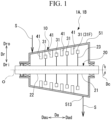
FIG. 1 is a schematic view showing an overall configuration of a steam turbine according to an embodiment of the present disclosure. -
FIG. 2 is a cross-sectional view showing a configuration around a diffuser according to a first embodiment of the steam turbine not forming part of the present invention but useful to its understanding. -
FIG. 3 is a cross-sectional view showing a configuration around a diffuser according to a second embodiment of the steam turbine according to the present invention - Hereinafter, an embodiment of a steam turbine according to the present disclosure will be described below with reference to the accompanying drawings. However, the present disclosure is not limited to the embodiment.
- As shown in
FIG. 1 , asteam turbine 1A of the present embodiment has arotor 20 that rotates about an axis O and acasing 10 that covers therotor 20. - For the convenience of the following description, a direction in which the axis O extends is referred to as an axial direction Da. In addition, a radial direction in the
rotor 20 with respect to the axis O is simply referred to as a radial direction Dr. Further, a circumferential direction of therotor 20 about the axis O is simply referred to as a circumferential direction Dc. - The
rotor 20 has arotor shaft 21 and arotor blade row 31. Therotor shaft 21 extends in the axial direction Da about the axis O. Therotor shaft 21 is rotatable about the axis O. Therotor shaft 21 has ashaft core portion 22 and a plurality ofdisc portions 23. Theshaft core portion 22 is formed in a columnar shape about the axis O and extends in the axial direction Da. The plurality ofdisc portions 23 are disposed at intervals in the axial direction Da. Eachdisc portion 23 is integrally formed with theshaft core portion 22 so as to constitute an outer peripheral portion of therotor shaft 21. Eachdisc portion 23 is disposed so as to extend from theshaft core portion 22 to the outer side Dro in the radial direction Dr. - The
rotor blade row 31 is fixed to the outer side Dro of therotor shaft 21 in the radial direction Dr. A plurality of rows ofrotor blade row 31 are disposed at intervals along the axial direction Da of therotor shaft 21. In the case of the present embodiment, therotor blade rows 31 are disposed in four rows, for example. Therefore, in the case of the present embodiment, therotor blade rows 31 are disposed from the first row to the fourth row ofrotor blade rows 31. - As shown in
FIG. 2 , therotor blade rows 31 of each row have a plurality ofrotor blades 32 arranged side by side in the circumferential direction Dc. The plurality ofrotor blades 32 are attached side by side on an outer circumference of thedisc portion 23. Eachrotor blade 32 has a rotor blademain body 33, ashroud 34, and aplatform 35. - Each rotor blade
main body 33 extends in the radial direction Dr. Theshroud 34 is disposed on the outer side Dro in the radial direction Dr with respect to the rotor blademain body 33. Theplatform 35 is disposed on an inner side Dri in the radial direction Dr with respect to the rotor blademain body 33. Theplatform 35 is fixed to thedisc portion 23. In therotor blade 32, a part of a steammain flow passage 15 which is a flow passage through which steam S flows is formed between theshroud 34 and theplatform 35. That is, the steammain flow passage 15 is formed between theshroud 34 positioned on an outer peripheral edge of therotor blade row 31 and theplatform 35 positioned on an inner peripheral edge of therotor blade row 31. By disposing a plurality ofrotor blades 32 side by side in the circumferential direction Dc, the steammain flow passage 15 is formed in an annular shape on the outer peripheral portion of therotor 20. - The
casing 10 is formed so as to cover therotor shaft 21, the plurality ofrotor blade rows 31, that is, therotor 20. Astator vane row 41 is fixed to the inner side Dri of the radial direction Dr in thecasing 10. A plurality ofstator vane rows 41 are disposed at intervals along the axial direction Da. In the present embodiment, the number of rows of thestator vane rows 41 is disposed in the same four rows as that of therotor blade rows 31. Thestator vane rows 41 are disposed so as to be arranged side by side at intervals on a first side Dau in the axial direction Da with respect to eachrotor blade row 31. Thestator vane row 41 constitutes one compression stage together with therotor blade row 31. Therefore, in the present embodiment, the four rows ofrotor blade rows 31 and thestator vane rows 41 constitute four compression stages having the fourth stages as the final stage. - The
stator vane row 41 of each row has a plurality ofstator vanes 42 arranged side by side in the circumferential direction Dc. Thestator vane row 41 has anouter ring 43, a stator vanemain body 44, and aninner ring 46. Theouter ring 43 is formed in an annular shape. Theouter ring 43 is disposed on the outer side Dro of the stator vanemain body 44 in the radial direction Dr. Theinner ring 46 is formed in an annular shape. Theinner ring 46 is disposed on the inner side Dri of the stator vanemain body 44 in the radial direction Dr. An annular space between theouter ring 43 and theinner ring 46 forms a part of the steammain flow passage 15 through which the steam S flows. - The steam
main flow passage 15 extends in the axial direction Da across a plurality ofrotor blade rows 31 andstator vane rows 41. Here, the first side Dau in the axial direction Da is the upstream side in the flow direction of the steam S in the steammain flow passage 15. In addition, a second side Dad in the axial direction Da is on the opposite side to the first side Dau, and is the downstream side in the flow direction of the steam S in the steammain flow passage 15. That is, the steam S flows in thecasing 10 from the first side Dau to the second side Dad in the axial direction Da. - The
casing 10 includes anexhaust casing 51 and adiffuser 70. Theexhaust casing 51 is connected to the outside of thecasing 10. Theexhaust casing 51 discharges the steam S flowing through the steammain flow passage 15 to the outside of thecasing 10. Theexhaust casing 51 is disposed on the second side Dad farthest in the axial direction Da in thecasing 10. An exhaust port 513 (refer toFIG. 1 ) that opens downward is formed in a lower portion of theexhaust casing 51. Theexhaust casing 51 exhausts the steam S whose static pressure has been recovered by thediffuser 70, which will be described later, to the outside through theexhaust port 513. - The
diffuser 70 guides the steam S flowing out from therotor blade row 31F of the final stage, which is disposed on the second side Dad farthest in the axial direction Da among a plurality of therotor blade rows 31, to the outside of thecasing 10 via theexhaust casing 51. Thediffuser 70 is disposed between therotor blade row 31F of the final stage and theexhaust casing 51. Thediffuser 70 of the present embodiment has anouter guide 71 and aninner guide 72. - The
outer guide 71 is disposed on the second side Dad in the axial direction Da with respect to therotor blade row 31F of the final stage. Theouter guide 71 is formed so as to gradually expand to the outer side Dro in the radial direction Dr from the first side Dau to the second side Dad in the axial direction Da. Theouter guide 71 of the present embodiment is curved so as to be convex toward the inner side Dri in the radial direction Dr. Theouter guide 71 has a first diameter-expandedportion 711 and a second diameter-expandedportion 712. - The first diameter-expanded
portion 711 is disposed on the first side Dau farthest in the axial direction Da in theouter guide 71. That is, in the present embodiment, the first diameter-expandedportion 711 is disposed at a position closest to therotor blade row 31F of the final stage in theouter guide 71. The first diameter-expandedportion 711 is formed so as to gradually expand to the outer side Dro in the radial direction Dr at a first radius of curvature R1 from the first side Dau to the second side Dad in the axial direction Da. The first diameter-expandedportion 711 is formed in a curved plate shape with the first radius of curvature R1 in a cross-sectional view parallel to and orthogonal to the axis O. Specifically, the first diameter-expandedportion 711 is formed by curving, in a cross-sectional view parallel to and orthogonal to the axis O, such that anintermediate portion 7113 of the diameter-enlarged portion in the axial direction Da extends to the inner side Dri in the radial direction Dr with respect to afirst end 7111 of the first diameter-enlarged portion of the first side Dau in the axial direction Da and asecond end 7112 of the second diameter-enlarged portion of the second side Dad in the axial direction Da. - The second diameter-expanded
portion 712 is disposed on the second side Dad in the axial direction Da with respect to the first diameter-expandedportion 711. The second diameter-expandedportion 712 is integrally formed so as to be connected to the first diameter-expandedportion 711 by the second side Dad in the axial direction Da. In the present embodiment, the second diameter-expandedportion 712 is formed so as to gradually expand to the outer side Dro in the radial direction Dr from the first side Dau to the second side Dad in the axial direction Da. The second diameter-expandedportion 712 has a second radius of curvature R2 larger than the first radius of curvature R1 and gradually expands to the outer side in the radial direction Dr. The second diameter-expandedportion 712 is formed in a curved plate shape with the second radius of curvature R2 in a cross-sectional view parallel to and orthogonal to the axis O. Specifically, the second radius of curvature R2 is preferably as large as possible with respect to the first radius of curvature R1. That is, the second diameter-expandedportion 712 expands more slowly than the first diameter-expandedportion 711. In the present embodiment, the second diameter-expandedportion 712 linearly expands in diameter from the first side Dau to the second side Dad in the axial direction Da. - The
inner guide 72 is disposed at intervals in the inner side Dri in the radial direction with respect to theouter guide 71. As a result, anannular flow passage 100, which is the flow passage through which the steam S can flow, is defined between theouter guide 71 and theinner guide 72. Theannular flow passage 100 is defined between theouter guide 71 and theinner guide 72 so as to form an annular shape when viewed from the axial direction Da. Theannular flow passage 100 is connected to the steammain flow passage 15 by the second side Dad in the axial direction Da. Theinner guide 72 is formed so as to gradually expand to the outer side Dro in the radial direction Dr from the first side Dau to the second side Dad in the axial direction Da with a third radius of curvature R3. Theinner guide 72 has an inner curved diameter-expandedportion 73. The inner curved diameter-expandedportion 73 is formed in a curved plate shape with the third radius of curvature R3 in a cross-sectional view parallel to and orthogonal to the axis O. Specifically, the inner curved diameter-expandedportion 73 is formed by curving, in a cross-sectional view parallel to and orthogonal to the axis O, such that anintermediate portion 733 of the inner guide between afirst end 731 of the inner guide and asecond end 732 of the inner guide extends to the inner side Dri in the radial direction Dr with respect to thefirst end 731 of the inner guide of the first side Dau in the axial direction Da and thesecond end 732 of the inner guide of the second side Dad in the axial direction Da. The third radius of curvature R3 is preferably set be larger than the first radius of curvature R1 of the first diameter-expandedportion 711. In the present embodiment, the third radius of curvature R3 is larger than the first radius of curvature R1 and smaller than the second radius of curvature R2. The third radius of curvature R3 is not limited to being smaller than the second radius of curvature R2 as long as the third radius of curvature R3 is larger than the first radius of curvature R1. Accordingly, the third radius of curvature R3 may be the same as the second radius of curvature R2. - In addition, the
diffuser 70 is divided into a first region P1 positioned on the first side Dau in the axial direction Da and a second region P2 positioned on the second side Dad in the axial direction Da. - The first region P1 is a region closest to the
rotor blade row 31F of the final stage in the axial direction Da. The first diameter-expandedportion 711 is disposed in the first region P1. In the first region P1, a part of the inner curved diameter-expandedportion 73 including thefirst end 731 of the inner guide is disposed. - The second region P2 is a region connected to the first region P1 by a second side Dad in the axial direction Da. The second diameter-expanded
portion 712 is disposed in the second region P2. A part of the inner curved diameter-expandedportion 73 including thesecond end 732 of the inner guide is disposed in the second region P2. - In addition, a length L2 of the second region P2 in the axial direction Da is preferably, for example, about 0.5 to 2.0 times a length L1 of the first region P1 in the axial direction Da. Here, the length L1 of the first region P1 and the length L2 of the second region P2 are the lengths near the center of the
annular flow passage 100 in the radial direction Dr in each region. Further, the length L2 of the second region P2 is preferably about 0.7 to 1.5 times the length L1 of the first region P1. In particular, the length L2 of the second region P2 is further preferably about 0.8 to 1.2 times the length L1 of the first region P1. - Generally, when the
steam turbine 1A is in rated operation, the flow velocity (average flow velocity) of the steam S flowing out from therotor blade row 31F of the final stage may be the transonic speed. Further, the flow velocity distribution of the steam S flowing out from therotor blade row 31F of the final stage gradually increases from the inner side Dri to the outer side Dro in the radial direction Dr due to the influence of the centrifugal force by therotor blade row 31. Therefore, when the flow velocity of the steam S flowing out from therotor blade row 31F of the final stage is transonic speed, the flow velocity of the steam S is further increased in a region close to theshroud 34. Accordingly, in theannular flow passage 100, the steam S flows obliquely toward the outer side Dro in the radial direction Dr with respect to the axis O. As a result, the steam S flowing in thediffuser 70 is easily peeled off from a wall surface forming thediffuser 70 before flowing into theexhaust casing 51. When the peeling occurs, the exhaust loss increases. - On the other hand, in the
steam turbine 1A having the above-described configuration, the inner curved diameter-expandedportion 73 is curved. Accordingly, the steam S flowing out from therotor blade row 31F of the final stage flows along the inner curved diameter-expandedportion 73 in the portion close to theinner guide 72 in the radial direction Dr. As a result, in the vicinity of the inner curved diameter-expandedportion 73, the steam S flows such that the flow direction is changed to the outer side Dro in the radial direction Dr while suppressing the peeling from the inner curved diameter-expandedportion 73. In addition, the first diameter-expandedportion 711 is curved with the first radius of curvature R1. Therefore, the steam S flowing out from therotor blade row 31F of the final stage flows, in the first region P1, along the first diameter-expandedportion 711 in the portion close to theouter guide 71 in the radial direction Dr. By flowing the steam S along the curved surface, the steam S flowing out from therotor blade row 31F of the final stage can be efficiently guided. After that, the steam S flowing in the portion close to theouter guide 71 in the radial direction Dr flows, in the second region P2, along the second diameter-expandedportion 712. The second diameter-expandedportion 712 slowly expands to the outer side Dro in the radial direction Dr as compared with the first diameter-expandedportion 711. Thus, the second diameter-expandedportion 712 is formed along the direction in which the steam S flowing from the first diameter-expandedportion 711 peels off. Therefore, the flow of the steam S can be suppressed to the inner side Dri in the radial direction Dr as compared with when the second diameter-expandedportion 712 is formed with the first radius of curvature R1 such that the first diameter-expandedportion 711 is extended as it is. Therefore, the steam S flowing along the first diameter-expandedportion 711 flows along the second diameter-expandedportion 712 without causing peeling. In this way, by increasing the radius of curvature on the downstream side (second side Dad) of theouter guide 71, it is possible to suppress the occurrence of peeling in the flow of the steam S on the outer side Dro in the radial direction Dr. In this way, thediffuser 70 can reduce the flow velocity while suppressing the peeling of the steam S. Therefore, even when the flow velocity (average flow velocity) of the steam S flowing out from therotor blade row 31F of the final stage is transonic speed, the occurrence of peeling can be suppressed. Accordingly, it is possible to efficiently recover the static pressure of the steam S in thediffuser 70. - In addition, in the
steam turbine 1B, the third radius of curvature R3 of the inner curved diameter-expandedportion 73 is larger than the first radius of curvature R1 of the first diameter-expandedportion 711. Thus, the occurrence of peeling can be efficiently suppressed even on the inner side Dri in the radial direction Dr. As a result, it becomes possible to more efficiently recover the static pressure of the steam S in thediffuser 70. - In addition, in the
steam turbine 1A, the length L2 of the axial direction Da of the second region P2 is 0.5 to 2.0 times the length L1 of the axial direction Da of the first region P1. That is, the length of the second diameter-expandedportion 712 in the axial direction Da is 0.5 to 2.0 times the length of the first diameter-expandedportion 711 in the axial direction Da. As a result, the flow velocity of the steam S can be adjusted in a well-balanced manner in the first region P1 and the second region P2. Therefore, it is possible to efficiently recover the static pressure. - In the second embodiment described below, the same reference numerals are given in the drawings to the configurations common to the first embodiment, and the description thereof will be omitted.
- As shown in
FIG. 3 , in thesteam turbine 1B of the second embodiment, the structure of thediffuser 60 is different from that of the first embodiment. - The
diffuser 60 of the second embodiment has anouter guide 61 and aninner guide 62. - The
outer guide 61 is disposed on the second side Dad in the axial direction Da with respect to therotor blade row 31F of the final stage. Theouter guide 61 is formed so as to gradually expand to the outer side Dro in the radial direction Dr from the first side Dau to the second side Dad in the axial direction Da. Theouter guide 61 has a firstinclined portion 611 and a secondinclined portion 612. - The first
inclined portion 611 is disposed on the first side Dau farthest in the axial direction Da in theouter guide 61. That is, in the present embodiment, the firstinclined portion 611 is disposed at a position closest to therotor blade row 31F of the final stage in theouter guide 61. The firstinclined portion 611 is formed so as to gradually expand to the outer side Dro in the radial direction Dr from the first side Dau to the second side Dad in the axial direction Da. The firstinclined portion 611 is inclined at a first inclination angle θ1 with respect to the axis O in a cross-sectional view parallel to and orthogonal to the axis O. The firstinclined portion 611 is formed in a flat plate shape in a cross-sectional view parallel to and orthogonal to the axis O. That is, the firstinclined portion 611 is formed linearly in a cross-sectional view parallel to and orthogonal to the axis O. - The second
inclined portion 612 is disposed on the second side Dad in the axial direction Da with respect to the firstinclined portion 611. The secondinclined portion 612 is formed integrally with the firstinclined portion 611. The secondinclined portion 612 is formed so as to gradually expand to the outer side Dro in the radial direction Dr from the first side Dau to the second side Dad in the axial direction Da. The secondinclined portion 612 is inclined at a second inclination angle θ2 larger than the first inclination angle θ1 with respect to the axis O in a cross-sectional view parallel to and orthogonal to the axis O. The secondinclined portion 612 is formed in a flat plate shape in a cross-sectional view parallel to and orthogonal to the axis O. That is, the secondinclined portion 612 is formed linearly in a cross-sectional view parallel to and orthogonal to the axis O. - The
inner guide 62 is disposed at intervals in the inner side Dri in the radial direction Dr with respect to theouter guide 61. As a result, anannular flow passage 100, which is the flow passage through which the steam S can flow, is defined between theouter guide 61 and theinner guide 62. Theinner guide 62 is formed so as to gradually expand to the outer side Dro in the radial direction Dr from the first side Dau to the second side Dad in the axial direction Da. The length of the axial direction Da of theinner guide 62 is formed to be longer than the length of the axial direction Da of theouter guide 61. Theinner guide 62 extends to be longer than theouter guide 61 on the second side Dad in the axial direction Da. Theinner guide 62 is inclined at a third inclination angle θ3 with respect to the axis O in a cross-sectional view parallel to and orthogonal to the axis O. Theinner guide 62 is formed in a flat plate shape in a cross-sectional view parallel to and orthogonal to the axis O. Accordingly, theinner guide 62 is formed so as to extend linearly and straight without bending even once from thefirst end 621 of the inner guide of the first side Dau in the axial direction Da toward thesecond end 622 of the inner guide of the second side Dad in the axial direction Da in a cross sectional view parallel and perpendicular to the axis O. The angle of the third inclination angle θ3 with respect to the axis O is larger than that of the first inclination angle θ1 and smaller than that of the second inclination angle θ2. - The first
inclined portion 611 is disposed in the first region P11 of the second embodiment. A part of theinner guide 62 including thefirst end 621 of the inner guide is disposed in the first region P11. In the first region P11, a cross-sectional area of theannular flow passage 100, which is a flow passage defined between theouter guide 61 and theinner guide 62, gradually decreases from the first side Dau to the second side Dad in the axial direction Da. That is, in the first region P11, the cross-sectional area of theannular flow passage 100 is maximum on the first side Dau in the axial direction Da and minimum on the second side Dad in the axial direction Da. The minimum cross-sectional area A1 min of theannular flow passage 100 in the first region P11 is formed to be larger than a cross-sectional area Aw of the steammain flow passage 15 in therotor blade row 31F of the final stage. - The second
inclined portion 612 is disposed in the second region P12 of the second embodiment. A part of theinner guide 62 including thesecond end 622 of the inner guide is disposed in the second region P12. In the second region P12, a cross-sectional area A2 of theannular flow passage 100 is formed so as to gradually increase toward the second side Dad in the axial direction Da. That is, in the second region P12, the cross-sectional area of theannular flow passage 100 is the minimum on the first side Dau in the axial direction Da and maximum on the second side Dad in the axial direction Da. The maximum cross-sectional area A2max of theannular flow passage 100 in the second region P12 is formed so as to be larger than the maximum cross-sectional area A1 max of theannular flow passage 100 in the first flow passage 101. - In addition, a length L2 of the second region P12 in the axial direction Da is preferably, for example, about 0.5 to 2.0 times a length L1 of the first region P11 in the axial direction Da. Further, the length L2 of the second region P12 is preferably about 0.7 to 1.5 times the length L1 of the first region P11. In particular, the length L2 of the second region P12 is further preferably about 0.8 to 1.2 times the length L1 of the first region P11.
- In a case where the flow velocity (average flow velocity) of the steam S flowing out from the
rotor blade row 31F of the final stage when thesteam turbine 1B is in rated operation is subsonic speed, the flow velocity of the steam S may further increase in a region close to theshroud 34 to become supersonic speed. On the other hand, in the present embodiment, in the first region P11 of thediffuser 60, the cross-sectional area A1 of theannular flow passage 100 gradually becomes smaller toward the second side Dad in the axial direction Da. Theannular flow passage 100 is narrowed, so that the flow velocity (mach number) of the steam S flowing out from therotor blade row 31F of the final stage is entirely reduced in the first region P11. As a result, the flow velocity of the steam S in a region close to theouter guide 61 in the radial direction Dr in the first region P11 is reduced from supersonic speed to subsonic speed. After that, the steam S flows from the first region P11 to the second region P12. The flow velocity of the steam S in the second region P12 is further reduced by gradually increasing the cross-sectional area A2 of theannular flow passage 100 toward the second side Dad in the axial direction Da while being reduced to the subsonic speed. Thus, the static pressure can be recovered. Accordingly, even when the flow velocity of the steam S flowing out from therotor blade row 31F of the final stage is subsonic speed, it is possible to efficiently recover the static pressure of the steam S in thediffuser 60. - In addition, in the
steam turbine 1B, the minimum cross-sectional area A1 min of theannular flow passage 100 in the first region P11 is larger than the cross-sectional area Aw of the steammain flow passage 15 formed between the outer peripheral edge and the inner peripheral edge of therotor blade row 31F of the final stage. As a result, it is possible to suppress the flow of steam S flowing out from therotor blade row 31F of the final stage from being choked in the first region P11 (the flow rate does not change even if the pressure ratio is large). - In addition, in the
steam turbine 1B, the maximum cross-sectional area A2max of theannular flow passage 100 in the second region P12 is larger than the maximum cross-sectional area A1 max of theannular flow passage 100 in the first region P11. As a result, the flow velocity of the steam S flowing into the second region P12 after the flow velocity is reduced in the first region P11 can be surely reduced. - In addition, in the
steam turbine 1B, theinner guide 62 is formed so as to extend linearly from thefirst end 621 of the inner guide of the first side Dau in the axial direction Da toward thesecond end 622 of the inner guide of the second side Dad in the axial direction Da. Further, theinner guide 62 is inclined at the third inclination angle θ3 that is larger than the first inclination angle θ1 of the firstinclined portion 611 and smaller than the second inclination angle θ2 of the secondinclined portion 612. As a result, in theannular flow passage 100, the turbulence of the flow of the steam S at the inner side Dri in the radial direction Dr can be suppressed. - In addition, in the
steam turbine 1B, the length L2 of the axial direction Da of the second region P12 is 0.5 to 2.0 times the length L1 of the axial direction Da of the first region P11. As a result, the flow velocity of the steam S can be adjusted in a well-balanced manner in the first region P11 and the second region P12. Therefore, it is possible to efficiently recover the static pressure. - The embodiments of the present disclosure have been described in detail with reference to the drawings, but the specific configuration is not limited to the embodiments, and includes design changes and the like within the scope of the invention as defined in the appended set of claims.
- For example, the configuration of each part of the
steam turbines rotor blade row 31 and thestator vane row 41, can be changed as appropriate. -
- 1A, 1B: Steam turbine
- 10: Casing
- 15: Steam main flow passage
- 20: Rotor
- 21: Rotor shaft
- 22: Shaft core portion
- 23: Disc portion
- 31: Rotor blade row
- 31F: Rotor blade row of final stage
- 32: Rotor blade
- 33: Rotor blade main body
- 34: Shroud
- 35: Platform
- 41: Stator vane row
- 42: Stator vane
- 43: Outer ring
- 44: Stator vane main body
- 46: Inner ring
- 51: Exhaust casing
- 513: Exhaust port
- 60, 70: Diffuser
- 61, 71: Outer guide
- 611: First inclined portion
- 612: Second inclined portion
- 62, 72: Inner guide
- 621, 731: First end of inner guide
- 622, 732: Second end of inner guide
- 711: First diameter-expanded portion
- 7111: First end of diameter-expanded portion
- 7112: Second end of diameter-expanded portion
- 7113: Intermediate portion of diameter-expanded portion
- 712: Second diameter-expanded portion
- 73: Inner curved diameter-expanded portion
- 733: Inner guide intermediate portion
- 100: Annular flow passage
- A1: Cross-sectional area
- A1 max: Maximum cross-sectional area
- A1 min: Minimum cross-sectional area
- A2: Cross-sectional area
- A2max: Maximum cross-sectional area
- Aw: Cross-sectional area
- Da: Axial direction
- Dad: Second side
- Dau: First side
- Dc: Circumferential direction
- Dr: Radial direction
- Dri: Inner side
- Dro: Outer side
- O: Axis
- P1, P11: First region
- P2, P12: Second region
- R1: First radius of curvature
- R2: Second radius of curvature
- R3: Third radius of curvature
- S: Steam
- θ1: First inclination angle
- θ2: Second inclination angle
- θ3: Third inclination angle
Claims (4)
- A steam turbine (1B) comprising:a rotor shaft (21) that is configured to rotate about an axis (O);a plurality of rotor blade rows (31) that are fixed to an outer side of the rotor shaft (21) and disposed at intervals in an axial direction along which the axis extends;a casing (10) that covers the rotor shaft (21) and the plurality of rotor blade rows (31); andstator vane rows (41) that are fixed to the casing (10), wherein each of the stator vane rows (41) is disposed at intervals axially upstream of a respective rotor blade row of the plurality of rotor blade rows (41), whereinthe casing (10) has a diffuser (60) that is configured to guide steam flowing out from a rotor blade row (31F) of a final stage, that is disposed axially most downstream among the plurality of rotor blade rows (31), to an outside of the casing (10),the diffuser (60) includingan outer guide (61) that gradually expands radially outwards from its upstream end to its downstream end,an inner guide (62) that is disposed radially inwards of the outer guide (61) and gradually expands radially outwards from its upstream end to its downstream end, wherein an annular flow passage (100) is defined between the outer guide (61) and the inner guide (62), and characterized in that:
the diffuser (60) includesa first region (P11) that is a region closest to the rotor blade row (31F) of the final stage in the axial direction in which a cross-sectional area of the flow passage defined between the outer guide (61) and the inner guide (62) gradually decreases from one end to the other end in an axial downstream direction, anda second region (P12) that is connected to the first region (P11) on the downstream side in the axial direction, in which the cross-sectional area of the flow passage gradually increases from one end to the other end in an axial downstream direction. - The steam turbine according to claim 1, wherein
a minimum cross-sectional area of the flow passage in the first region (P11) is larger than a cross-sectional area of the flow passage defined between an outer peripheral edge and an inner peripheral edge of the rotor blade row (31) in the final stage. - The steam turbine according to claim 1 or 2, wherein
a maximum cross-sectional area of the flow passage in the second region (P12) is larger than a maximum cross-sectional area of the flow passage in the first region (P11). - The steam turbine according to any one of claims 1 to 3, whereinthe outer guide (61) includesa first inclined portion (611) that is disposed in the first region (P11) and is inclined at a first inclination angle (θ1) with respect to the axis (O), anda second inclined portion (612) that is disposed in the second region and is inclined at a second inclination angle (θ2) larger than the first inclination angle (θ1) with respect to the axis (O), andthe inner guide (62) is formed linearly from a first end of the inner guide (62) on the upstream side in the axial direction toward a second end of the inner guide (62) on the downstream side in the axial direction, and a third inclination angle (θ3) of the inner guide (62) with respect to the axis (O) is larger than the first inclination angle (θ1) and smaller than the second inclination angle (θ2).
Applications Claiming Priority (2)
| Application Number | Priority Date | Filing Date | Title |
|---|---|---|---|
| JP2020154499A JP7458947B2 (en) | 2020-09-15 | 2020-09-15 | Steam turbine |
| EP21187261.9A EP3967848B1 (en) | 2020-09-15 | 2021-07-22 | Steam turbine with exhaust diffuser |
Related Parent Applications (2)
| Application Number | Title | Priority Date | Filing Date |
|---|---|---|---|
| EP21187261.9A Division-Into EP3967848B1 (en) | 2020-09-15 | 2021-07-22 | Steam turbine with exhaust diffuser |
| EP21187261.9A Division EP3967848B1 (en) | 2020-09-15 | 2021-07-22 | Steam turbine with exhaust diffuser |
Publications (2)
| Publication Number | Publication Date |
|---|---|
| EP3998397A1 EP3998397A1 (en) | 2022-05-18 |
| EP3998397B1 true EP3998397B1 (en) | 2024-09-04 |
Family
ID=77042734
Family Applications (2)
| Application Number | Title | Priority Date | Filing Date |
|---|---|---|---|
| EP21217964.2A Active EP3998397B1 (en) | 2020-09-15 | 2021-07-22 | Steam turbine with diffuser |
| EP21187261.9A Active EP3967848B1 (en) | 2020-09-15 | 2021-07-22 | Steam turbine with exhaust diffuser |
Family Applications After (1)
| Application Number | Title | Priority Date | Filing Date |
|---|---|---|---|
| EP21187261.9A Active EP3967848B1 (en) | 2020-09-15 | 2021-07-22 | Steam turbine with exhaust diffuser |
Country Status (3)
| Country | Link |
|---|---|
| US (1) | US11702962B2 (en) |
| EP (2) | EP3998397B1 (en) |
| JP (1) | JP7458947B2 (en) |
Families Citing this family (2)
| Publication number | Priority date | Publication date | Assignee | Title |
|---|---|---|---|---|
| KR102707856B1 (en) * | 2022-02-07 | 2024-09-23 | 두산에너빌리티 주식회사 | Compressor to minimize vane tip clearance and gas turbine including the same |
| JP2024093395A (en) * | 2022-12-27 | 2024-07-09 | 三菱重工コンプレッサ株式会社 | Steam turbine |
Family Cites Families (13)
| Publication number | Priority date | Publication date | Assignee | Title |
|---|---|---|---|---|
| US3625630A (en) * | 1970-03-27 | 1971-12-07 | Caterpillar Tractor Co | Axial flow diffuser |
| JPS62174507A (en) * | 1986-01-27 | 1987-07-31 | Toshiba Corp | Exhaust diffuser for axial flow turbo machine |
| US5257906A (en) * | 1992-06-30 | 1993-11-02 | Westinghouse Electric Corp. | Exhaust system for a turbomachine |
| JP3564420B2 (en) * | 2001-04-27 | 2004-09-08 | 三菱重工業株式会社 | gas turbine |
| JP4342840B2 (en) | 2003-05-30 | 2009-10-14 | 株式会社東芝 | Steam turbine |
| US20120034064A1 (en) * | 2010-08-06 | 2012-02-09 | General Electric Company | Contoured axial-radial exhaust diffuser |
| US20120163969A1 (en) * | 2010-12-23 | 2012-06-28 | General Electric Company | Turbine including exhaust hood |
| JP5606373B2 (en) * | 2011-03-28 | 2014-10-15 | 株式会社東芝 | Steam turbine |
| EP2677123B2 (en) * | 2012-06-18 | 2018-04-25 | General Electric Technology GmbH | Diffuser for turbomachines |
| JP6334258B2 (en) * | 2013-08-28 | 2018-05-30 | 株式会社東芝 | Steam turbine |
| EP3054086B1 (en) | 2015-02-05 | 2017-09-13 | General Electric Technology GmbH | Steam turbine diffuser configuration |
| JP6847673B2 (en) | 2017-01-17 | 2021-03-24 | 株式会社東芝 | Turbine exhaust chamber |
| EP3653850B1 (en) * | 2018-11-16 | 2021-09-29 | Doosan Skoda Power S.r.o. | Exhaust diffuser for a steam turbine and corresponding steam turbine |
-
2020
- 2020-09-15 JP JP2020154499A patent/JP7458947B2/en active Active
-
2021
- 2021-07-21 US US17/381,680 patent/US11702962B2/en active Active
- 2021-07-22 EP EP21217964.2A patent/EP3998397B1/en active Active
- 2021-07-22 EP EP21187261.9A patent/EP3967848B1/en active Active
Also Published As
| Publication number | Publication date |
|---|---|
| EP3967848A1 (en) | 2022-03-16 |
| US11702962B2 (en) | 2023-07-18 |
| EP3967848B1 (en) | 2023-05-10 |
| US20220082025A1 (en) | 2022-03-17 |
| JP2022048602A (en) | 2022-03-28 |
| JP7458947B2 (en) | 2024-04-01 |
| EP3998397A1 (en) | 2022-05-18 |
Similar Documents
| Publication | Publication Date | Title |
|---|---|---|
| US8308421B2 (en) | Axial turbine | |
| EP3564537B1 (en) | Centrifugal compressor and turbocharger | |
| EP1921278A1 (en) | Diffuser and exhaust system for turbine | |
| EP2886875B1 (en) | Centrifugal compressor | |
| EP2540967A2 (en) | Supersonic turbine moving blade and axial-flow turbine | |
| EP3663514B1 (en) | Steam turbine blade and steam turbine | |
| WO2018181343A1 (en) | Centrifugal compressor | |
| EP3967848B1 (en) | Steam turbine with exhaust diffuser | |
| CN110418896B (en) | Return Stage and Radial Turbine Fluid Energy Machinery | |
| JP4869974B2 (en) | Axial flow turbine | |
| EP3561312B1 (en) | Centrifugal compressor | |
| JP2019157807A (en) | Centrifugal pump | |
| US8870532B2 (en) | Exhaust hood diffuser | |
| JP7336026B2 (en) | Turbine and turbocharger with this turbine | |
| KR102223293B1 (en) | Rotating machine, exhaust member of rotating machine | |
| JP4515404B2 (en) | Axial flow turbine | |
| EP3686439B1 (en) | Multi-stage centrifugal compressor | |
| EP3839263B1 (en) | Shrouded impeller with shroud reinforcing struts in the impeller suction eye | |
| JP6178268B2 (en) | Turbine blades and steam turbines | |
| JP2020186729A (en) | Centrifugal compressor |
Legal Events
| Date | Code | Title | Description |
|---|---|---|---|
| PUAI | Public reference made under article 153(3) epc to a published international application that has entered the european phase |
Free format text: ORIGINAL CODE: 0009012 |
|
| STAA | Information on the status of an ep patent application or granted ep patent |
Free format text: STATUS: REQUEST FOR EXAMINATION WAS MADE |
|
| 17P | Request for examination filed |
Effective date: 20211228 |
|
| AC | Divisional application: reference to earlier application |
Ref document number: 3967848 Country of ref document: EP Kind code of ref document: P |
|
| AK | Designated contracting states |
Kind code of ref document: A1 Designated state(s): AL AT BE BG CH CY CZ DE DK EE ES FI FR GB GR HR HU IE IS IT LI LT LU LV MC MK MT NL NO PL PT RO RS SE SI SK SM TR |
|
| GRAP | Despatch of communication of intention to grant a patent |
Free format text: ORIGINAL CODE: EPIDOSNIGR1 |
|
| STAA | Information on the status of an ep patent application or granted ep patent |
Free format text: STATUS: GRANT OF PATENT IS INTENDED |
|
| INTG | Intention to grant announced |
Effective date: 20240216 |
|
| GRAS | Grant fee paid |
Free format text: ORIGINAL CODE: EPIDOSNIGR3 |
|
| GRAA | (expected) grant |
Free format text: ORIGINAL CODE: 0009210 |
|
| STAA | Information on the status of an ep patent application or granted ep patent |
Free format text: STATUS: THE PATENT HAS BEEN GRANTED |
|
| AC | Divisional application: reference to earlier application |
Ref document number: 3967848 Country of ref document: EP Kind code of ref document: P |
|
| AK | Designated contracting states |
Kind code of ref document: B1 Designated state(s): AL AT BE BG CH CY CZ DE DK EE ES FI FR GB GR HR HU IE IS IT LI LT LU LV MC MK MT NL NO PL PT RO RS SE SI SK SM TR |
|
| REG | Reference to a national code |
Ref country code: GB Ref legal event code: FG4D |
|
| REG | Reference to a national code |
Ref country code: CH Ref legal event code: EP |
|
| REG | Reference to a national code |
Ref country code: IE Ref legal event code: FG4D |
|
| REG | Reference to a national code |
Ref country code: DE Ref legal event code: R096 Ref document number: 602021018264 Country of ref document: DE |
|
| REG | Reference to a national code |
Ref country code: LT Ref legal event code: MG9D |
|
| REG | Reference to a national code |
Ref country code: NL Ref legal event code: MP Effective date: 20240904 |
|
| PG25 | Lapsed in a contracting state [announced via postgrant information from national office to epo] |
Ref country code: NO Free format text: LAPSE BECAUSE OF FAILURE TO SUBMIT A TRANSLATION OF THE DESCRIPTION OR TO PAY THE FEE WITHIN THE PRESCRIBED TIME-LIMIT Effective date: 20241204 |
|
| PG25 | Lapsed in a contracting state [announced via postgrant information from national office to epo] |
Ref country code: PL Free format text: LAPSE BECAUSE OF FAILURE TO SUBMIT A TRANSLATION OF THE DESCRIPTION OR TO PAY THE FEE WITHIN THE PRESCRIBED TIME-LIMIT Effective date: 20240904 Ref country code: GR Free format text: LAPSE BECAUSE OF FAILURE TO SUBMIT A TRANSLATION OF THE DESCRIPTION OR TO PAY THE FEE WITHIN THE PRESCRIBED TIME-LIMIT Effective date: 20241205 Ref country code: FI Free format text: LAPSE BECAUSE OF FAILURE TO SUBMIT A TRANSLATION OF THE DESCRIPTION OR TO PAY THE FEE WITHIN THE PRESCRIBED TIME-LIMIT Effective date: 20240904 |
|
| PG25 | Lapsed in a contracting state [announced via postgrant information from national office to epo] |
Ref country code: BG Free format text: LAPSE BECAUSE OF FAILURE TO SUBMIT A TRANSLATION OF THE DESCRIPTION OR TO PAY THE FEE WITHIN THE PRESCRIBED TIME-LIMIT Effective date: 20240904 |
|
| PG25 | Lapsed in a contracting state [announced via postgrant information from national office to epo] |
Ref country code: LV Free format text: LAPSE BECAUSE OF FAILURE TO SUBMIT A TRANSLATION OF THE DESCRIPTION OR TO PAY THE FEE WITHIN THE PRESCRIBED TIME-LIMIT Effective date: 20240904 |
|
| PG25 | Lapsed in a contracting state [announced via postgrant information from national office to epo] |
Ref country code: HR Free format text: LAPSE BECAUSE OF FAILURE TO SUBMIT A TRANSLATION OF THE DESCRIPTION OR TO PAY THE FEE WITHIN THE PRESCRIBED TIME-LIMIT Effective date: 20240904 |
|
| PG25 | Lapsed in a contracting state [announced via postgrant information from national office to epo] |
Ref country code: RS Free format text: LAPSE BECAUSE OF FAILURE TO SUBMIT A TRANSLATION OF THE DESCRIPTION OR TO PAY THE FEE WITHIN THE PRESCRIBED TIME-LIMIT Effective date: 20241204 Ref country code: ES Free format text: LAPSE BECAUSE OF FAILURE TO SUBMIT A TRANSLATION OF THE DESCRIPTION OR TO PAY THE FEE WITHIN THE PRESCRIBED TIME-LIMIT Effective date: 20240904 |
|
| PG25 | Lapsed in a contracting state [announced via postgrant information from national office to epo] |
Ref country code: RS Free format text: LAPSE BECAUSE OF FAILURE TO SUBMIT A TRANSLATION OF THE DESCRIPTION OR TO PAY THE FEE WITHIN THE PRESCRIBED TIME-LIMIT Effective date: 20241204 Ref country code: PL Free format text: LAPSE BECAUSE OF FAILURE TO SUBMIT A TRANSLATION OF THE DESCRIPTION OR TO PAY THE FEE WITHIN THE PRESCRIBED TIME-LIMIT Effective date: 20240904 Ref country code: NO Free format text: LAPSE BECAUSE OF FAILURE TO SUBMIT A TRANSLATION OF THE DESCRIPTION OR TO PAY THE FEE WITHIN THE PRESCRIBED TIME-LIMIT Effective date: 20241204 Ref country code: LV Free format text: LAPSE BECAUSE OF FAILURE TO SUBMIT A TRANSLATION OF THE DESCRIPTION OR TO PAY THE FEE WITHIN THE PRESCRIBED TIME-LIMIT Effective date: 20240904 Ref country code: HR Free format text: LAPSE BECAUSE OF FAILURE TO SUBMIT A TRANSLATION OF THE DESCRIPTION OR TO PAY THE FEE WITHIN THE PRESCRIBED TIME-LIMIT Effective date: 20240904 Ref country code: GR Free format text: LAPSE BECAUSE OF FAILURE TO SUBMIT A TRANSLATION OF THE DESCRIPTION OR TO PAY THE FEE WITHIN THE PRESCRIBED TIME-LIMIT Effective date: 20241205 Ref country code: FI Free format text: LAPSE BECAUSE OF FAILURE TO SUBMIT A TRANSLATION OF THE DESCRIPTION OR TO PAY THE FEE WITHIN THE PRESCRIBED TIME-LIMIT Effective date: 20240904 Ref country code: ES Free format text: LAPSE BECAUSE OF FAILURE TO SUBMIT A TRANSLATION OF THE DESCRIPTION OR TO PAY THE FEE WITHIN THE PRESCRIBED TIME-LIMIT Effective date: 20240904 Ref country code: BG Free format text: LAPSE BECAUSE OF FAILURE TO SUBMIT A TRANSLATION OF THE DESCRIPTION OR TO PAY THE FEE WITHIN THE PRESCRIBED TIME-LIMIT Effective date: 20240904 |
|
| REG | Reference to a national code |
Ref country code: AT Ref legal event code: MK05 Ref document number: 1720604 Country of ref document: AT Kind code of ref document: T Effective date: 20240904 |
|
| PG25 | Lapsed in a contracting state [announced via postgrant information from national office to epo] |
Ref country code: NL Free format text: LAPSE BECAUSE OF FAILURE TO SUBMIT A TRANSLATION OF THE DESCRIPTION OR TO PAY THE FEE WITHIN THE PRESCRIBED TIME-LIMIT Effective date: 20240904 |
|
| PG25 | Lapsed in a contracting state [announced via postgrant information from national office to epo] |
Ref country code: IS Free format text: LAPSE BECAUSE OF FAILURE TO SUBMIT A TRANSLATION OF THE DESCRIPTION OR TO PAY THE FEE WITHIN THE PRESCRIBED TIME-LIMIT Effective date: 20250104 Ref country code: PT Free format text: LAPSE BECAUSE OF FAILURE TO SUBMIT A TRANSLATION OF THE DESCRIPTION OR TO PAY THE FEE WITHIN THE PRESCRIBED TIME-LIMIT Effective date: 20250106 |
|
| PG25 | Lapsed in a contracting state [announced via postgrant information from national office to epo] |
Ref country code: RO Free format text: LAPSE BECAUSE OF FAILURE TO SUBMIT A TRANSLATION OF THE DESCRIPTION OR TO PAY THE FEE WITHIN THE PRESCRIBED TIME-LIMIT Effective date: 20240904 Ref country code: SM Free format text: LAPSE BECAUSE OF FAILURE TO SUBMIT A TRANSLATION OF THE DESCRIPTION OR TO PAY THE FEE WITHIN THE PRESCRIBED TIME-LIMIT Effective date: 20240904 |
|
| PG25 | Lapsed in a contracting state [announced via postgrant information from national office to epo] |
Ref country code: EE Free format text: LAPSE BECAUSE OF FAILURE TO SUBMIT A TRANSLATION OF THE DESCRIPTION OR TO PAY THE FEE WITHIN THE PRESCRIBED TIME-LIMIT Effective date: 20240904 Ref country code: AT Free format text: LAPSE BECAUSE OF FAILURE TO SUBMIT A TRANSLATION OF THE DESCRIPTION OR TO PAY THE FEE WITHIN THE PRESCRIBED TIME-LIMIT Effective date: 20240904 |
|
| PG25 | Lapsed in a contracting state [announced via postgrant information from national office to epo] |
Ref country code: CZ Free format text: LAPSE BECAUSE OF FAILURE TO SUBMIT A TRANSLATION OF THE DESCRIPTION OR TO PAY THE FEE WITHIN THE PRESCRIBED TIME-LIMIT Effective date: 20240904 |
|
| PG25 | Lapsed in a contracting state [announced via postgrant information from national office to epo] |
Ref country code: SK Free format text: LAPSE BECAUSE OF FAILURE TO SUBMIT A TRANSLATION OF THE DESCRIPTION OR TO PAY THE FEE WITHIN THE PRESCRIBED TIME-LIMIT Effective date: 20240904 |
|
| REG | Reference to a national code |
Ref country code: DE Ref legal event code: R097 Ref document number: 602021018264 Country of ref document: DE |
|
| PG25 | Lapsed in a contracting state [announced via postgrant information from national office to epo] |
Ref country code: DK Free format text: LAPSE BECAUSE OF FAILURE TO SUBMIT A TRANSLATION OF THE DESCRIPTION OR TO PAY THE FEE WITHIN THE PRESCRIBED TIME-LIMIT Effective date: 20240904 |
|
| PLBE | No opposition filed within time limit |
Free format text: ORIGINAL CODE: 0009261 |
|
| STAA | Information on the status of an ep patent application or granted ep patent |
Free format text: STATUS: NO OPPOSITION FILED WITHIN TIME LIMIT |
|
| 26N | No opposition filed |
Effective date: 20250605 |
|
| PG25 | Lapsed in a contracting state [announced via postgrant information from national office to epo] |
Ref country code: SE Free format text: LAPSE BECAUSE OF FAILURE TO SUBMIT A TRANSLATION OF THE DESCRIPTION OR TO PAY THE FEE WITHIN THE PRESCRIBED TIME-LIMIT Effective date: 20240904 |
|
| PGFP | Annual fee paid to national office [announced via postgrant information from national office to epo] |
Ref country code: DE Payment date: 20250528 Year of fee payment: 5 |
|
| PGFP | Annual fee paid to national office [announced via postgrant information from national office to epo] |
Ref country code: IT Payment date: 20250623 Year of fee payment: 5 |
|
| REG | Reference to a national code |
Ref country code: CH Ref legal event code: H13 Free format text: ST27 STATUS EVENT CODE: U-0-0-H10-H13 (AS PROVIDED BY THE NATIONAL OFFICE) Effective date: 20260224 |
|
| PG25 | Lapsed in a contracting state [announced via postgrant information from national office to epo] |
Ref country code: LU Free format text: LAPSE BECAUSE OF NON-PAYMENT OF DUE FEES Effective date: 20250722 |
|
| GBPC | Gb: european patent ceased through non-payment of renewal fee |
Effective date: 20250722 |
|
| REG | Reference to a national code |
Ref country code: BE Ref legal event code: MM Effective date: 20250731 |
|
| PG25 | Lapsed in a contracting state [announced via postgrant information from national office to epo] |
Ref country code: GB Free format text: LAPSE BECAUSE OF NON-PAYMENT OF DUE FEES Effective date: 20250722 |
|
| PG25 | Lapsed in a contracting state [announced via postgrant information from national office to epo] |
Ref country code: BE Free format text: LAPSE BECAUSE OF NON-PAYMENT OF DUE FEES Effective date: 20250731 |
|
| PG25 | Lapsed in a contracting state [announced via postgrant information from national office to epo] |
Ref country code: FR Free format text: LAPSE BECAUSE OF NON-PAYMENT OF DUE FEES Effective date: 20250731 |
|
| PG25 | Lapsed in a contracting state [announced via postgrant information from national office to epo] |
Ref country code: CH Free format text: LAPSE BECAUSE OF NON-PAYMENT OF DUE FEES Effective date: 20250731 |