EP3998239A1 - Electrolytic assembly and laundry treatment apparatus - Google Patents
Electrolytic assembly and laundry treatment apparatus Download PDFInfo
- Publication number
- EP3998239A1 EP3998239A1 EP19940515.0A EP19940515A EP3998239A1 EP 3998239 A1 EP3998239 A1 EP 3998239A1 EP 19940515 A EP19940515 A EP 19940515A EP 3998239 A1 EP3998239 A1 EP 3998239A1
- Authority
- EP
- European Patent Office
- Prior art keywords
- electrolytic
- anode
- electrode
- electrolytic assembly
- cathode
- Prior art date
- Legal status (The legal status is an assumption and is not a legal conclusion. Google has not performed a legal analysis and makes no representation as to the accuracy of the status listed.)
- Granted
Links
Images





Classifications
-
- C—CHEMISTRY; METALLURGY
- C02—TREATMENT OF WATER, WASTE WATER, SEWAGE, OR SLUDGE
- C02F—TREATMENT OF WATER, WASTE WATER, SEWAGE, OR SLUDGE
- C02F1/00—Treatment of water, waste water, or sewage
- C02F1/46—Treatment of water, waste water, or sewage by electrochemical methods
- C02F1/461—Treatment of water, waste water, or sewage by electrochemical methods by electrolysis
- C02F1/46104—Devices therefor; Their operating or servicing
-
- C—CHEMISTRY; METALLURGY
- C02—TREATMENT OF WATER, WASTE WATER, SEWAGE, OR SLUDGE
- C02F—TREATMENT OF WATER, WASTE WATER, SEWAGE, OR SLUDGE
- C02F1/00—Treatment of water, waste water, or sewage
- C02F1/46—Treatment of water, waste water, or sewage by electrochemical methods
- C02F1/461—Treatment of water, waste water, or sewage by electrochemical methods by electrolysis
- C02F1/46104—Devices therefor; Their operating or servicing
- C02F1/4618—Devices therefor; Their operating or servicing for producing "ionised" acidic or basic water
-
- C—CHEMISTRY; METALLURGY
- C02—TREATMENT OF WATER, WASTE WATER, SEWAGE, OR SLUDGE
- C02F—TREATMENT OF WATER, WASTE WATER, SEWAGE, OR SLUDGE
- C02F1/00—Treatment of water, waste water, or sewage
- C02F1/46—Treatment of water, waste water, or sewage by electrochemical methods
- C02F1/4606—Treatment of water, waste water, or sewage by electrochemical methods for producing oligodynamic substances to disinfect the water
-
- C—CHEMISTRY; METALLURGY
- C02—TREATMENT OF WATER, WASTE WATER, SEWAGE, OR SLUDGE
- C02F—TREATMENT OF WATER, WASTE WATER, SEWAGE, OR SLUDGE
- C02F1/00—Treatment of water, waste water, or sewage
- C02F1/46—Treatment of water, waste water, or sewage by electrochemical methods
- C02F1/461—Treatment of water, waste water, or sewage by electrochemical methods by electrolysis
- C02F1/46104—Devices therefor; Their operating or servicing
- C02F1/46109—Electrodes
-
- D—TEXTILES; PAPER
- D06—TREATMENT OF TEXTILES OR THE LIKE; LAUNDERING; FLEXIBLE MATERIALS NOT OTHERWISE PROVIDED FOR
- D06F—LAUNDERING, DRYING, IRONING, PRESSING OR FOLDING TEXTILE ARTICLES
- D06F35/00—Washing machines, apparatus, or methods not otherwise provided for
- D06F35/003—Washing machines, apparatus, or methods not otherwise provided for using electrochemical cells
-
- D—TEXTILES; PAPER
- D06—TREATMENT OF TEXTILES OR THE LIKE; LAUNDERING; FLEXIBLE MATERIALS NOT OTHERWISE PROVIDED FOR
- D06F—LAUNDERING, DRYING, IRONING, PRESSING OR FOLDING TEXTILE ARTICLES
- D06F39/00—Details of washing machines not specific to a single type of machines covered by groups D06F9/00 - D06F27/00
- D06F39/04—Heating arrangements
-
- C—CHEMISTRY; METALLURGY
- C02—TREATMENT OF WATER, WASTE WATER, SEWAGE, OR SLUDGE
- C02F—TREATMENT OF WATER, WASTE WATER, SEWAGE, OR SLUDGE
- C02F1/00—Treatment of water, waste water, or sewage
- C02F1/46—Treatment of water, waste water, or sewage by electrochemical methods
- C02F1/461—Treatment of water, waste water, or sewage by electrochemical methods by electrolysis
- C02F1/46104—Devices therefor; Their operating or servicing
- C02F1/4618—Devices therefor; Their operating or servicing for producing "ionised" acidic or basic water
- C02F2001/46185—Devices therefor; Their operating or servicing for producing "ionised" acidic or basic water only anodic or acidic water, e.g. for oxidizing or sterilizing
-
- C—CHEMISTRY; METALLURGY
- C02—TREATMENT OF WATER, WASTE WATER, SEWAGE, OR SLUDGE
- C02F—TREATMENT OF WATER, WASTE WATER, SEWAGE, OR SLUDGE
- C02F2101/00—Nature of the contaminant
- C02F2101/30—Organic compounds
-
- C—CHEMISTRY; METALLURGY
- C02—TREATMENT OF WATER, WASTE WATER, SEWAGE, OR SLUDGE
- C02F—TREATMENT OF WATER, WASTE WATER, SEWAGE, OR SLUDGE
- C02F2101/00—Nature of the contaminant
- C02F2101/30—Organic compounds
- C02F2101/308—Dyes; Colorants; Fluorescent agents
-
- C—CHEMISTRY; METALLURGY
- C02—TREATMENT OF WATER, WASTE WATER, SEWAGE, OR SLUDGE
- C02F—TREATMENT OF WATER, WASTE WATER, SEWAGE, OR SLUDGE
- C02F2201/00—Apparatus for treatment of water, waste water or sewage
- C02F2201/46—Apparatus for electrochemical processes
- C02F2201/461—Electrolysis apparatus
- C02F2201/46105—Details relating to the electrolytic devices
- C02F2201/46155—Heating or cooling
-
- C—CHEMISTRY; METALLURGY
- C02—TREATMENT OF WATER, WASTE WATER, SEWAGE, OR SLUDGE
- C02F—TREATMENT OF WATER, WASTE WATER, SEWAGE, OR SLUDGE
- C02F2209/00—Controlling or monitoring parameters in water treatment
- C02F2209/02—Temperature
-
- C—CHEMISTRY; METALLURGY
- C02—TREATMENT OF WATER, WASTE WATER, SEWAGE, OR SLUDGE
- C02F—TREATMENT OF WATER, WASTE WATER, SEWAGE, OR SLUDGE
- C02F2303/00—Specific treatment goals
- C02F2303/04—Disinfection
-
- C—CHEMISTRY; METALLURGY
- C02—TREATMENT OF WATER, WASTE WATER, SEWAGE, OR SLUDGE
- C02F—TREATMENT OF WATER, WASTE WATER, SEWAGE, OR SLUDGE
- C02F2307/00—Location of water treatment or water treatment device
- C02F2307/12—Location of water treatment or water treatment device as part of household appliances such as dishwashers, laundry washing machines or vacuum cleaners
-
- Y—GENERAL TAGGING OF NEW TECHNOLOGICAL DEVELOPMENTS; GENERAL TAGGING OF CROSS-SECTIONAL TECHNOLOGIES SPANNING OVER SEVERAL SECTIONS OF THE IPC; TECHNICAL SUBJECTS COVERED BY FORMER USPC CROSS-REFERENCE ART COLLECTIONS [XRACs] AND DIGESTS
- Y02—TECHNOLOGIES OR APPLICATIONS FOR MITIGATION OR ADAPTATION AGAINST CLIMATE CHANGE
- Y02B—CLIMATE CHANGE MITIGATION TECHNOLOGIES RELATED TO BUILDINGS, e.g. HOUSING, HOUSE APPLIANCES OR RELATED END-USER APPLICATIONS
- Y02B40/00—Technologies aiming at improving the efficiency of home appliances, e.g. induction cooking or efficient technologies for refrigerators, freezers or dish washers
Definitions
- the application relates to the technical field of electrolytic sterilization, and in particular to an electrolytic assembly and a laundry treatment apparatus.
- ⁇ OH hydroxyl free radical
- embodiments of the application are intended to provide an electrolytic assembly with a heating function and a laundry treatment apparatus.
- an aspect of the embodiments of the application provides an electrolytic assembly including: an electrolytic device, including an electrode; a heating member; and a mounting device, to which at least one of the electrolytic device or the heating member is connected, and the heating member and the electrode are located on the same side of the mounting device.
- the electrolytic device includes a conductive connector in conductive connection with the electrode, the mounting device has formed therein a first mounting hole penetrating it, and the conductive connector is hermetically arranged in the first mounting hole in a penetrating manner.
- an end of the heating member is hermetically arranged in a second mounting hole in a penetrating manner.
- the electrolytic assembly includes a first fastener connecting the electrode to the heating member.
- the heating member includes a first rod and a second rod, and the electrode is located between the first rod and the second rod.
- the electrolytic assembly includes a first insulator located between the first rod and the second rod and mounted to sleeve the electrode, and a first fastener surrounding outer surfaces of the first rod, the second rod and the first insulator.
- At least one of a top surface or a bottom surface of the first insulator is formed with a first groove in which a part of the first fastener is located.
- the electrode includes at least one layer of electrode units.
- each of the electrode units includes a cathode sub-member and an anode sub-member which are arranged at an interval
- the cathode sub-member includes a first support and at least one first comb-shaped tooth extending from the first support along a direction away from the first support
- the anode sub-member includes a second support and at least one second comb-shaped tooth extending from the second support along a direction away from the second support
- the first comb-shaped tooth and the second comb-shaped tooth are alternately arranged at an interval.
- the first comb-shaped tooth includes a first sub-tooth and a second sub-tooth which are arranged at an interval along a thickness direction of the cathode sub-member; and the second comb-shaped tooth includes a third sub-tooth and a fourth sub-tooth which are arranged at an interval along a thickness direction of the anode sub-member.
- the electrode units have multiple layers; and the electrolytic assembly includes separation pads which are arranged between adjacent two of the electrode units.
- each of the separation pads has formed therein first through holes penetrating the separation pad along a thickness direction thereof.
- each of the electrode units includes a cathode sub-member and an anode sub-member which are arranged at an interval, and a protrusion is formed on a surface of each of the separation pads, and extends into a space between the cathode sub-member and the anode sub-member on the same side of the separation pad.
- the electrolytic assembly includes second insulators, each of which at least a part is clamped between a cathode and an anode forming the electrode.
- each of the second insulators includes a base clamped between the cathode and the anode and columns protruding out of a surface of the base, the anode is provided with through holes, and each of the columns is arranged in a respective one of the through holes in a penetrating manner.
- the electrolytic assembly includes buckles and second fasteners, through which the heating member and the electrode are fixedly connected.
- each of the buckles includes a connecting section located between the first rod and the second rod and snapping sections located at two opposite ends of the connecting section, one of the snapping sections is snapped on the first rod, and the other of the snapping sections is snapped on the second rod.
- multiple buckles are present, and arranged at intervals along a length direction of at least one of the first rod or the second rod.
- the buckles are arranged on two opposite sides along a stacking direction of the cathode and the anode, the cathode and the anode are clamped between two of the buckles, and the cathode, the anode and the two of the buckles are fixedly connected through the second fasteners.
- an end face of each of the columns protrudes out of a surface of the anode, and abuts against the connecting section and an interval space is formed between the connecting section and the anode, a first connecting hole penetrating each of the columns and the base is formed in the second insulator, second connecting holes are formed in the connecting section, third connecting holes are formed in the cathode, and each of the second fasteners is arranged in a respective one of the first connecting holes, the second connecting holes and the third connecting holes in a penetrating manner.
- the electrolytic assembly includes insulated limiting members clamped in the interval space.
- At least one second through hole is formed in each of the insulated limiting members, and each of the columns is arranged in a respective one of the second through holes in a penetrating manner.
- each of the insulated limiting members has formed therein a second through hole in which a respective one of the columns is arranged in a penetrating manner, one of the insulated limiting members is arranged between two of the columns, and formed with open notches at two opposite ends thereof along the extending direction of the connecting section, and each of the open notches is matched with a respective one of the columns.
- each of the insulated limiting members is provided with a second groove extending along an extending direction of the connecting section, and a part of the connecting section is located in the second groove.
- the anode is provided with second through holes penetrating the anode along a thickness direction thereof; and/or, the cathode is provided with third through holes penetrating the cathode along a thickness direction thereof.
- the anode is formed in a net-shaped structure
- the cathode is formed in a net-shaped structure
- the electrolytic assembly includes a temperature controller
- the mounting device has formed therein a third mounting hole penetrating it
- the temperature controller is hermetically arranged in the third mounting hole in a penetrating manner, and an end, configured to measure temperature, of the temperature controller is located on a side, facing the electrode, of the mounting device.
- the mounting device includes a connector and a main body including a first mounting plate, a second mounting plate and an elastic body clamped between the first mounting plate and the second mounting plate; the mounting device has formed therein a connecting hole in which the connector is hermetically arranged in a penetrating manner; and the first mounting hole, the second mounting hole and the connecting hole penetrate the first mounting plate, the elastic body and the second mounting plate respectively.
- a second aspect of the embodiments of the application provides a laundry treatment apparatus including: an inner cylinder; an outer cylinder, in which the inner cylinder is arranged in a rotatable manner, and having formed therein an avoiding opening; and the electrolytic assembly in any of the above descriptions, having the electrode and the heating member arranged between the outer cylinder and the inner cylinder, and having the mounting device sealing the avoiding opening.
- the laundry treatment apparatus includes a mounting support connected to an inner side of the outer cylinder and supporting the heating member.
- the electrolytic assembly may generate ⁇ OH having a strong oxidization activity by electrolyzing water by means of the electrolytic device to perform sterilization and disinfection, and may further heat a liquid to a required temperature by means of the heating member.
- the mounting device integrates the heating member and the electrolytic device together, to facilitate more compact structural arrangement of the heating member and the electrolytic device on one hand, and facilitate assembly/disassembly of the whole electrolytic assembly on the other hand, to facilitate updating and replacement of a product.
- the electrolytic assembly applied to the laundry treatment apparatus is taken as an example, when an existing laundry treatment apparatus is provided with a heating member but is not provided with an electrolytic device, in case that the electrolytic device needs to be added for sterilization and disinfection to improve performance of the product, the existing heating member may be detached, then the electrolytic assembly provided by the application may be mounted at an original position where the heating member is mounted, therefore the laundry treatment apparatus may be upgraded and replaced in case that other mounting structures of the laundry treatment apparatus are basically not changed, providing good interchangeability and low production cost.
- orientation or position relationships indicated by terms “top” and “bottom” are based on orientation or position relationships as shown in FIG. 4 , and it should be understood that the orientation terms are intended only to conveniently describe the application and simplify descriptions, rather than to indicate or imply that devices or components indicated by them must be in specific orientations or structured and operated in specific orientations, and thus should not be understood as limitations of the application.
- a thickness direction of an electrode is consistent with a direction indicated by "top” and “bottom” shown in FIG. 4 .
- the electrolytic assembly 1000 includes: an electrolytic device, including an electrode 11; a heating member 2; and a mounting device 3, to which at least one of the electrolytic device or the heating member 2 is connected, and the electrode 11 and the heating member 2 are located on the same side of the mounting device 3.
- the electrolytic assembly 1000 may generate ⁇ OH having a strong oxidization activity by electrolyzing water by means of the electrolytic device to perform sterilization and disinfection, and may further heat a liquid to a required temperature by means of the heating member 2.
- the mounting device 3 integrates the heating member 2 and the electrolytic device together, to facilitate more compact structural arrangement of the heating member 2 and the electrolytic device on one hand, and facilitate assembly/disassembly of the whole electrolytic assembly on the other hand, to facilitate updating and replacement of a product.
- the electrolytic assembly 1000 applied to the laundry treatment apparatus is taken as an example, when an existing laundry treatment apparatus is provided with a heating member but is not provided with an electrolytic device, in case that the electrolytic device needs to be added for sterilization and disinfection to improve performance of the product, the existing heating member may be detached, then the electrolytic assembly 1000 provided by the application may be mounted at an original position where the heating member is mounted, therefore the laundry treatment apparatus may be upgraded and replaced in case that other mounting structures of the laundry treatment apparatus are basically not changed, providing good interchangeability and low production cost.
- the electrolytic device is connected to the mounting device 3, and the heating member 2 is connected to the electrolytic device, that is, the heating member 2 is indirectly connected to the mounting device 3 through the electrolytic device; in the second case, the heating member 2 is connected to the mounting device 3, the heating member 2 is connected to the electrolytic device, and the electrolytic device is indirectly connected to the mounting device through the heating member 2; and in the third case, each of the electrolytic device and the heating member 2 is connected to the mounting device 3.
- the electrode 11 and the heating member 2 are located on the same side of the mounting device 3, which means that most of the structure, with a heating function, of the heating member 2 and the electrode 11 are located on the same side of the mounting device 3.
- the electrolytic device includes a conductive connector 12 in conductive connection with the electrode 11, the mounting device 3 has formed therein a first mounting hole (not shown in the figure) penetrating it, and the conductive connector 12 is hermetically arranged in the first mounting hole in a penetrating manner, and water leakage may be avoided at the first mounting hole.
- the mounting device 3 has formed therein a second mounting hole (not shown in the figure) penetrating it, and an end of the heating member 2 is hermetically arranged in the second mounting hole in a penetrating manner, and water leakage may be avoided at the second mounting hole.
- the mounting device 3 has both the first mounting hole and the second mounting hole, that is, each of the electrolytic device and the heating member 2 is connected to the mounting device 3.
- the electrode 11 includes a cathode 11' and an anode 11
- the conductive connector 12 includes a cathode conductive connector 12' in conductive connection with the cathode 11' and an anode conductive connector 12" in conductive connection with the anode 11"
- the electrode 11 is connected with a power supply through the conductive connector 12.
- the cathode 11' and the anode 11" are spaced apart from each other, i.e., the cathode 11' and the anode 11" do not contact with each other at any position, and guaranteeing normal operation of the electrolytic device. It may be understood that referring to FIG.
- a first terminal 12a may be fastened to an end of the conductive connector 12 by welding or the like, for example, the conductive connector 12 is fastened to the first terminal 12a after penetrating the first mounting hole.
- the heating member 2 may be an electric heating tube, such as a glass heating tube, a stainless steel heating tube, a quartz heating tube, a ceramic heating tube or the like.
- the heating member 2 may be made into different shapes.
- the heating member 2 includes a first rod 210, a second rod 211, and a transition body 212 connected between the first rod 210 and the second rod 211, a gap is formed between the first rod 210 and the second rod 211, the electrode 11 is located between the first rod 210 and the second rod 211, i.e., the electrode 11 is located in the gap, therefore on one hand, the first rod 210 and the second rod 211 may be kept at a distance from each other, and the heating area is increased, and on the other hand, an accommodating space may be provided for the electrode 11, and the electrolytic assembly 1000 may be more compact in structure.
- the first rod 210, the second rod 211 and the transition body 212 may be integrally formed.
- the transition body 212 may be made in various desired shapes.
- a second terminal 22a may be fastened to an end of the heating member 2 by welding or the like. Specifically, an end of the heating member 2 is fastened to the second terminal 22a after penetrating the second mounting hole.
- the heating member 2 itself may have a temperature control function, for example, a bimetallic strip is placed in the heating tube, the bimetallic strip is formed by combining two metallic strips made of different materials together through a special process, the bimetallic strip deforms according to temperature variations due to different expansion coefficients when the temperature changes, a contact switch is formed in the heating tube by using the bimetallic strip, and the contact switch may be automatically switched off to control the temperature after the temperature is reached.
- a bimetallic strip is placed in the heating tube, the bimetallic strip is formed by combining two metallic strips made of different materials together through a special process, the bimetallic strip deforms according to temperature variations due to different expansion coefficients when the temperature changes, a contact switch is formed in the heating tube by using the bimetallic strip, and the contact switch may be automatically switched off to control the temperature after the temperature is reached.
- a temperature control structure may be additionally arranged outside of the heating member 2 to control the heating temperature.
- the electrolytic assembly 1000 includes a temperature controller 4, the mounting device 3 has formed therein a third mounting hole (not shown in the figure) penetrating it, the temperature controller 4 is hermetically arranged in the third mounting hole in a penetrating manner, and water leakage may be avoided at the third mounting hole, and an end, configured to measure temperature, of the temperature controller 4 is located on a side, facing the electrode, of the mounting device 3.
- the temperature controller 4 is also integrally mounted on the mounting device 3, to improve the integration level of the electrolytic assembly 1000 and reduce the mounting difficulty.
- the type of the temperature controller 4 is not limited.
- FIGS. 1-16 illustrate a schematic structural diagram of an electrolytic assembly according to a first implementation of the application.
- the electrolytic assembly 1000 further includes a first fastener 61 connecting the electrode 11 to the heating member 2, and the first fastener 61 fixedly connects the electrode 11 to the heating member 2 to enhance a structural strength between the electrode 11 and the heating member 2.
- the electrode 11 is mounted on the mounting device 3 through the conductive connector 12, the electrode 11 may be in a cantilever state, and force bearing condition of the electrode 11 may be improved through the first fastener 61 and the heating member 2, working life of the electrolytic assembly 1000 is prolonged, and working reliability of the electrolytic assembly 1000 is improved.
- the specific mechanism of the first fastener 61 is not limited.
- the electrolytic assembly 1000 includes a first insulator 51 and the first fastener 61, the first insulator 51 is arranged between the first rod 210 and the second rod 211, and referring to FIG. 10 , a first through hole 51b is formed in the first insulator 51, the electrode 11 is arranged in the first through hole 51b in a penetrating mode, that is, the first insulator 51 is mounted to sleeve the electrode 11, therefore the electrode 11 may be electrically insulated from the first rod 210 and the second rod 211.
- the first fastener 61 is approximately ringshaped, and referring to FIG. 2 , the first fastener 61 surrounds outer surfaces of the first rod 210, the second rod 211 and the first insulator 51.
- the electrode 11, the first rod 210 and the second rod 211 are bound together by the first fastener 61, and preventing the first insulator 51 from separating from the electrode 11 and the heating member 2.
- the first insulator 51 may be made of a material having a damping property, such as rubber, silica gel or the like.
- the first fastener 61 may be an iron wire, a strap or the like.
- At least one of a top surface or a bottom surface of the first insulator 51 is formed with a first groove 51a in which a part of the first fastener 61 is located, therefore the first groove 51a forms a limiting stop of the first fastener 61 to prevent the first fastener 61 from separating from the first insulator 51.
- the structure of the electrode 11 is not limited.
- the electrode 11 includes at least one layer of electrode units 11′′′, and each layer of electrode units 11′′′ includes a cathode sub-member 110 and an anode sub-member 111.
- each layer of electrode units 11′′′ includes a cathode sub-member 110 and an anode sub-member 111.
- the cathode sub-members 110 in the multiple layers of electrode units 11′′′ constitute the cathode 11' together
- the anode sub-members 111 in the multiple layers of electrode units 11′′′ constitute the anode 11".
- the cathode sub-member 110 is the cathode
- the anode sub-member 111 is the anode.
- the cathode sub-member 110 includes a first support 1102 and at least one first comb-shaped tooth 1101 extending from the first support 1102 along a direction away from the first support 1102; and the anode sub-member 111 includes a second support 1112 and at least one second comb-shaped tooth 1111 extending from the second support 1112 along a direction away from the second support 1112; and the first comb-shaped tooth 1101 and the second comb-shaped tooth 1111 are alternately arranged at an interval, that is, the first comb-shaped tooth 1101 and the second comb-shaped tooth 1111 are formed in an interdigital structure.
- the first comb-shaped tooth 1101 and the second comb-shaped tooth 1111 are formed in an interdigital structure, and on one hand, the electrode unit 11′′′ has a larger working surface area, the electrolytic efficiency of the electrolytic device is improved, and on the other hand, the electrode unit 11′′′ only needs to occupy a smaller space, therefore the electrolytic device may be compact in structure.
- the electrolytic device applied to the laundry treatment apparatus is taken as an example, during washing laundries, fluffs on laundries are mixed into water, since a gap between the first comb-shaped tooth 1101 and the second comb-shaped tooth 1111 is a long and narrow gap, fluffs may easily pass through the long and narrow gap, that is, fluffs are not easy to block the electrolytic device, and the service life of the electrolytic device may be prolonged.
- the cathode sub-member 110 and the anode sub-member 111 do not overlap, the cathode sub-member 110 and the anode sub-member 111 do not contact with each other even if the cathode sub-member 110 and the anode sub-member 111 displace under an action of the external force, and thus a short circuit caused by contact between the cathode sub-member 110 and the anode sub-member 111 may be effectively prevented.
- a thickness of the assembly of the cathode sub-member 110 and the anode sub-member 111 may be designed to be very small, which is beneficial for the light and thin design of the electrolytic device, and the electrolytic device may be installed in a narrow space, for example, between an inner cylinder and an outer cylinder of the laundry treatment apparatus.
- life of the electrolytic device needs to match with designed service life of the laundry treatment apparatus, and when the life of the electrolytic device is substantially shorter than the designed service life of the laundry treatment apparatus, the laundry treatment apparatus may be scrapped in advance and consumers' benefits are impaired.
- impurities such as fluffs or the like do not block the electrode 11, and thus the life of the electrolytic device may reach the designed service life of the laundry treatment apparatus.
- the specific structural form of the first comb-shaped tooth 1101 is not limited, and the first comb-shaped tooth 1101 may be formed in a sheet shape, a column shape, a strip shape or the like.
- the specific structural form of the second comb-shaped tooth 1111 is not limited, and the second comb-shaped tooth 1111 may be formed in a sheet shape, a column shape, a strip shape or the like.
- the cross section of the column shape is not limited in shape and may be circular, polygonal or the like.
- the structure of the first comb-shaped tooth 1101 is substantially the same as that of the second comb-shaped tooth 1111, the first comb-shaped tooth 1101 is substantially parallel to the second comb-shaped tooth 1111, and the first support 1102 is substantially parallel to the second support 1112, and the electrolytic device is more compact in structure and neat and attractive in appearance.
- the first comb-shaped tooth 1101 includes a first sub-tooth 11011 and a second sub-tooth 11012 which are arranged at an interval along a thickness direction of the cathode 11', that is, the first support 1102 has a thickness, and the first sub-tooth 11011 and the second sub-tooth 11012 share the same first support 1102; and the second comb-shaped tooth 1111 includes a third sub-tooth 11111 and a fourth sub-tooth 11112 which are arranged at an interval along a thickness direction of the anode 11", that is, the second support 1112 has a thickness, and the third sub-tooth 11111 and the fourth sub-tooth 11112 share the same second support 1112.
- the electrolytic area may be increased, and the electrolytic efficiency may be improved.
- the electrode units 11′′′ have multiple layers, the multiple layers of electrode units 11′′′ are stacked together to form the electrode 11, the cathode sub-members 110 of the multiple layers of electrode units 11′′′ may be fastened into a whole component through a fastener, and the anode sub-members 111 of the multiple layers of electrode units 11′′′ may be fastened into a whole component through a fastener.
- the electrolytic assembly 1000 includes separation pads 7 which are arranged between adjacent two of the electrode units 11′′′. The number of the separation pads 7 depends on the number of the electrode units 11′′′.
- multiple cathode sub-members 110 are electrically connected to the cathode conductive connector 12'
- multiple anode sub-members 111 are electrically connected to the anode conductive connector 12".
- the cathode sub-members 110 and the cathode conductive connector 12' may be connected by welding, or may be connected by screws, bolts or the like.
- the anode sub-members 111 and the anode conductive connector 12" may be connected by welding, or may be connected by screws, bolts or the like.
- each of the electrode units 11′′′ is approximately formed in a flat structure, thus the structure is simple, machining and manufacturing cost thereof is low, manufacturing thereof is easy, standardized mass production thereof may be realized, and during assembly, the number of the electrode units 11′′′ to be stacked may be determined according to the needs of applications.
- each of the separation pads 7 has formed therein first through holes 7a penetrating the separation pad 7 along a thickness direction thereof, and the liquid may flow among multiple electrode units 11′′′ and scour the surface of the electrode 11 to timely take away tiny bubbles on the surface of the electrode 11.
- a protrusion 71 is formed on a surface of each of the separation pads 7, and there may be one or more protrusions 71.
- the protrusion 71 extends into a space between the cathode sub-member 110 and the anode sub-member 111 of the electrode unit 11′′′ located on the same layer.
- the position of the protrusion 71 is not limited, for example, the protrusion 71 may extend into the gap between the first comb-shaped tooth 1101 and the second comb-shaped tooth 1111, therefore a short circuit caused by contact between the first comb-shaped tooth 1101 and the second comb-shaped tooth 1111 man be prevented; the protrusion 71 may also extend into a gap between an end of the first comb-shaped tooth 1101 and the second support 1112, and a short circuit caused by contact between the first comb-shaped tooth 1101 and the second support 1112 may be prevented; and the protrusion 71 may also extend into a gap between an end of the second comb-shaped tooth 1111 and the first support 1102, and a short circuit caused by contact between the second comb-shaped tooth 1111 and the first support 1102 may be prevented. In the case that there are multiple protrusions 71, it is also possible to arrange the protrusion 71 at each of the above positions.
- the mounting device 3 includes a connector 32 and a main body 31 has formed therein the first mounting hole, the second mounting hole, the third mounting hole and a connecting hole penetrating it, and each of the first mounting holes, the second mounting holes, the third mounting hole and the connecting hole penetrates from one side of the main body 31 to the other side of the main body 31.
- the connector 32 is hermetically arranged in the connecting hole in a penetrating manner.
- the cathode conductive connector 12' is arranged in one of the first mounting holes in a penetrating manner
- the anode conductive connector 12" is arranged in the other of the first mounting holes in a penetrating manner.
- the first rod 210 is arranged in one of the second mounting holes in a penetrating manner
- the second rod 211 is arranged in the other of the second mounting holes in a penetrating manner.
- the main body 31 includes a first mounting plate 310, a second mounting plate 311 and an elastic body 312.
- the first mounting plate 310 is arranged on a side, facing the electrode 11, of the elastic body 312
- the second mounting plate 311 is arranged on a side, away from the electrode 11, of the elastic body 312, and the elastic body 312 is clamped between the first mounting plate 310 and the second mounting plate 311.
- the first mounting hole, the second mounting hole, the third mounting hole and the connecting hole penetrate the first mounting plate 310, the second mounting plate 311 and the elastic body 312 respectively.
- the connector 32 may be a connection structure formed by a bolt and a nut together.
- the first mounting plate 310 and the second mounting plate 311 are tensioned through the connector 32, and the elastic body 312 deforms by bearing a force, an inner wall of the first mounting hole abuts against the conductive connector 12 in a sealing manner, an inner wall of the second mounting hole abuts against the heating member 2 in a sealing manner, and the connector 32 abuts against an inner wall of the connecting hole in a sealing manner.
- an abutting surface 312a is formed along a circumferential direction of the elastic body 312.
- FIGS. 17-22 illustrate a schematic structural diagram of an electrolytic assembly according to a second implementation of the application.
- the electrode 11 includes a cathode 11' and an anode 11", each of the cathode 11' and the anode 11" is formed in a plate shape, and the cathode 11' and the anode 11" are arranged in a stack.
- the first rod 210 and the second rod 211 are arranged to be substantially parallel to each other, and a direction of stacking the cathode 11' and the anode 11" is perpendicular to a plane where the first rod 210 and the second rod 211 are located, and thus the electrolytic assembly 1000 is more compact in structure.
- the anode 11" is provided with second through holes 11c penetrating the anode 11" along a thickness direction thereof, and liquid flow may flow from one side of the anode 11" to the other side of the anode 11" through the second through holes 11c, and fluidity of water flow may be enhanced, and the water flow may take away microbubbles on the surface of the anode 11" in time to prevent the microbubbles from accumulating to become large.
- FIG. 18 the anode 11" is provided with second through holes 11c penetrating the anode 11" along a thickness direction thereof, and liquid flow may flow from one side of the anode 11" to the other side of the anode 11" through the second through holes 11c, and fluidity of water flow may be enhanced, and the water flow may take away microbubbles on the surface of the anode 11" in time to prevent the microbubbles from accumulating to become large.
- the cathode 11' is provided with third through holes 11d penetrating the cathode 11' in a thickness direction thereof, and liquid flow may flow from one side of the cathode 11' to the other side of the cathode 11' through the third through holes 11d, and fluidity of water flow may be enhanced, and the water flow may take away microbubbles on the surface of the cathode 11' in time to prevent the microbubbles from accumulating to become large.
- the electrolytic assembly 1000 includes second insulators 52, and further referring to FIG. 22 , at least a part of each of the second insulators 52 is clamped between the cathode 11' and the anode 11", and a short circuit caused by contact between the cathode 11' and the anode 11" may be avoided, and reliability of the electrolytic device is improved.
- each of the second insulators 52 includes a base 521 and columns 522 protruding out of a surface of the base 521, and further referring to FIG. 22 , the anode 11" is provided with through holes 11a, the base 522 is clamped between the cathode 11' and the anode 11", and each of the columns 522 is arranged in a respective one of the through holes 11a in a penetrating manner.
- the cathode 11' and the anode 11" may be effectively isolated through the base 521, and the anode 11" may be located through the column 522.
- the second insulator 52 may be made of a material having a damping property, such as rubber, silica gel or the like.
- the electrolytic assembly 1000 further includes a buckle 8 and second fasteners 62, and the buckle 8 and the electrode 11 are fixedly connected by the second fasteners 62 and the buckle 8.
- the electrode 11 may be attached to the heating member 2 through the second fasteners 62 and the buckle 8.
- the electrode 11 is mounted on the mounting device 3 through the conductive connector 12, the electrode 11 may be in a cantilever state, and force bearing condition of the electrode 11 may be improved through the heating member 2 after attaching the electrode 11 to the heating member 2, working life of the electrolytic assembly 1000 may be prolonged, and working reliability of the electrolytic assembly 1000 may be improved.
- the buckle 8 includes a connecting section 81 located between the first rod 210 and the second rod 211 and snapping sections 82 located at two opposite ends of the connecting section 81, one of the snapping sections 82 is snapped on the first rod 210, specifically, snapped to a side, away from the second rod 211, of the first rod 210.
- the other of the snapping sections 82 is snapped on the second rod 211, specifically, snapped to a side, away from the first rod 210, of the second rod 211.
- the buckle 8 is snapped on the first rod 210 and the second rod 211 through the snapping sections 82 at two ends, and the buckle 8 is prevented from moving relative to the heating member 2.
- the buckle 8 may be a metal member and the snapping sections 82 at two ends have greater structural strength and greater elastic deformation.
- the buckle 8 as described above may be used in pairs. Specifically, the buckles 8 are arranged on two opposite sides along a stacking direction of the cathode 11' and the anode 11", the cathode 11' and the anode 11" are clamped between two of the buckles 8, and the two buckles 8 and the electrode 11 are fixedly connected through the second fasteners 62.
- the second fastener 62 is a bolt which may securely lock the cathode 11' and the anode 11" between the two buckles 8.
- multiple buckles 8 are present, and arranged at intervals along a length direction of at least one of the first rod 210 or the second rod 211. It may be understood that multiple buckles 8 may be only present on a top side of the electrode; or multiple buckles 8 may be only present on a bottom side of the electrode; or multiple fasteners 8 may be present on both the top side and the bottom side of the electrode. That is, in the embodiment, multiple pairs of buckles 8 as described above are arranged at intervals along the length direction of at least one of the first rod 210 or the second rod 211, one pair of buckles includes one buckle on the top side of the electrode and one buckle on the bottom side of the electrode, and the two buckles are used in pair.
- an end face of each of the columns 522 protrudes out of a surface of the anode 11", and abuts against the connecting section 81 and an interval space is formed between the connecting section 81 and the anode 11", and the interval space may insulate and separate the connecting section and the anode 11" and electrochemical corrosion of the anode 11" may be prevented.
- a first connecting hole 52a penetrating each of the columns 522 and the base 521 is formed in the second insulator 52, second connecting holes 8a are formed in the connecting section 81, third connecting holes 11b are formed in the cathode 11", and each of the second fasteners 62 is arranged in a respective one of the first connecting holes 52a, the second connecting holes 8a and the third connecting holes 11b in a penetrating manner, that is, the second fastener 62 does not contact with the anode 11", and electrochemical corrosion of the anode 11" may be prevented.
- the buckle 8 may be made of a metal.
- the anode 11" in order to prevent the anode 11" from being in conductive contact with the heating member 2 or the second fastener 62, in an embodiment of the application, the anode 11" is provided with a through hole 11a, the column 522 is arranged in the through hole 11a of the anode 11" in a penetrating manner, the anode 11" may be electrically insulated from the cathode 11", the buckle 8 and the second fastener 62 under an action of the second insulator 52, and electrochemical corrosion of the anode 11" may be prevented.
- the electrolytic assembly 1000 further includes insulated limiting members 9 clamped in the interval space between the connecting section 81 and the anode 11", and capable of limiting the electrode 11 to prevent the electrode 11 from moving in the stacking direction.
- At least one second through hole 9b is formed in each of the insulated limiting members 9, and each of the columns 522 is arranged in a respective one of the second through holes 9b in a penetrating mode.
- a locating effect may be achieved on insulated limiting member 9 through the column 522, and the insulated limiting member 9 may be rapidly located and mounted during assembly.
- the number of the column 522 is greater than or equal to that of the second through hole 9b.
- multiple columns 522 are present, and arranged at intervals along an extending direction of the connecting section 81.
- each of the insulated limiting members 9 has formed therein a second through hole 9b in which a respective one of the columns 522 is arranged in a penetrating manner, one of the insulated limiting members 9 is arranged between two of the columns 522, that is, there are at least three columns 522, and each of the insulated limiting members 9 is formed with open notches 9c at two opposite ends thereof along the extending direction of the connecting section 81, and each of the open notches 9c is matched with the corresponding column 522.
- the open notches 9c at two ends the insulated limiting member 9 may be well located, and thus the insulated limiting member 9 is prevented from rotating.
- a size of the insulated limiting member 9 may be reduced, and the electrolytic assembly is simple in structure.
- each of the insulated limiting members 9 is provided with a second groove 9a extending along an extending direction of the connecting section 81, and a part of the connecting section 81 is located in the second groove 9a.
- the second groove 9a plays a role of locating the connecting section 81 in a direction perpendicular to the extending direction of the connecting section 81, and thus the connecting section 81 is prevented from sliding relative to the insulated limiting member 9.
- the structure of the mounting device is substantially the same as that in the first implementation, except that in the implementation, there is one first mounting hole, and the conductive connector of the anode and the conductive connector of the cathode share the one first mounting hole. It should be noted that the conductive connector of the cathode and the conductive connector of the anode remain electrically insulated even if they are arranged in the same first mounting hole.
- each of the cathode 11' and the anode 11" is formed in a net-shaped structure, that is, density of the third through holes 11d in the cathode 11' is large and the cathode 11' is formed in a net-shaped structure as a whole, and density of the second through holes 11c in the anode 11" is large and the anode 11" is in is formed in a net-shaped structure as a whole.
- a second aspect of the embodiments of the application provides a laundry treatment apparatus including an inner cylinder (not shown in the figure), an outer cylinder 2000, and the electrolytic assembly 1000 of any one of the above descriptions, here the inner cylinder is arranged in a rotatable manner in the outer cylinder 2000, and the outer cylinder 2000 has formed therein an avoiding opening (not shown in the figure), and the electrode 11 and the heating member 2 are arranged between the outer cylinder 2000 and the inner cylinder, and the mounting device 3 seals the avoiding opening.
- the electrolytic device during working, when the outer cylinder is filled with water, the electrolytic device is activated and may generate hydroxyl free radicals ( ⁇ OH) with a strong oxidation activity, ⁇ OH has an extremely high oxidation potential (2.80 eV) and extremely strong oxidation capacity, may generate a rapid chain reaction with most of organic pollutants, may realize sterilization and disinfection at a low temperature and does not damage laundries, a part of ⁇ OH react with chlorine water in tap water to generate active chlorine, and the active chlorine may exist for a long time and has a long-term bacteriostatic effect; and the electrolytic device generates a large amount of ⁇ OH to oxidize and destroy chromophoric groups of dye molecules of colored laundries dissociated into water during washing to decolorize dyes, and the dissociated dyes are prevented from staining light-color laundries to induce cross-color, and the dye molecules are decomposed into harmless carbon dioxide, water and inorganic salt through continuous
- a large number of hydrogen microbubbles may be generated by the electrode 11, since a diameter of each of the microbubbles is small, generally smaller than 50 um, the microbubbles may well enter an interior of laundry fibers during washing, circulating flushing of the microbubbles is continuously generated through blasting, adsorption and floating effects of the microbubbles, to assist a detergent to thoroughly remove sebum, grease, tiny dust and other dirt accumulated in the laundry fibers, and thus the washing effect may be improved.
- the laundry treatment apparatus may be a washing machine, a dewatering machine, or another type of apparatus, no limitation is made thereto. It may be understood that the washing machine may be a pulsator washing machine, or may be a drum washing machine, or may be a washing machine of another structural type.
- the laundry treatment apparatus includes a mounting support 3000 connected to an inner side of the outer cylinder 2000 and supporting the heating member 2.
- the mounting support 3000 plays a supporting role on the heating member 2, specifically, the mounting support 3000 and the mounting device 3 support the heating member 2 together, and the support of the heating member 2 is avoided to become a cantilever, and force bearing condition of the heating member 2 may be improved.
- the mounting support 3000 may be any suitable structure.
- the assembly of the electrolytic assembly 1000 and the outer cylinder 2000 will be described below by example of the laundry treatment apparatus being a drum washing machine.
- An axial side of the outer cylinder 2000 is provided with an opening, and the other side, opposite to the opening, of the outer cylinder is a closed end.
- the embodiment of the application is described by example of the avoiding opening being formed at the closed end, and it may be understood that the avoiding opening may also be formed in the circumference, following the rotation direction, of the outer cylinder 2000.
- the heating member 2, the mounting device 3 and the electrolytic device may form an integral structure in advance, and during assembly, the integral structure is placed into the avoiding opening from the outer side of the outer cylinder 2000, the elastic body 312 abuts against the periphery of the avoiding opening in a sealing manner, the electrolytic assembly is pushed inwards until the abutting face 312a of the elastic body 312 abuts against the outer surface of the outer cylinder, therefore, rapid and accurate locating of the electrolytic assembly is facilitated.
- the connector 32 is tensioned, the elastic body 312 generates elastic deformation, the parts, located around the avoiding opening in the inner side of the outer cylinder and around the avoiding opening in the outer side of the outer cylinder, of the elastic body 312 are bulged towards the periphery, then the elastic body 312 is clamped on the outer cylinder from both the inner direction and the outer direction, and quick sealed mounting may be realized simply and conveniently.
Landscapes
- Chemical & Material Sciences (AREA)
- Engineering & Computer Science (AREA)
- Electrochemistry (AREA)
- Chemical Kinetics & Catalysis (AREA)
- Life Sciences & Earth Sciences (AREA)
- General Chemical & Material Sciences (AREA)
- Hydrology & Water Resources (AREA)
- Environmental & Geological Engineering (AREA)
- Water Supply & Treatment (AREA)
- Organic Chemistry (AREA)
- Textile Engineering (AREA)
- Water Treatment By Electricity Or Magnetism (AREA)
- Electrolytic Production Of Non-Metals, Compounds, Apparatuses Therefor (AREA)
- Detail Structures Of Washing Machines And Dryers (AREA)
- Treatment Of Fiber Materials (AREA)
Abstract
Description
- The application claims priorities to
Chinese patent application No. 201910722803.0 filed on August 6, 2019 Chinese patent application No. 201910722785.6 filed on August 6, 2019 Chinese patent application No. 201911222522.5 filed on December 3, 2019 Chinese patent application No. 201922138237.7 filed on December 3, 2019 - The application relates to the technical field of electrolytic sterilization, and in particular to an electrolytic assembly and a laundry treatment apparatus.
- Due to an extremely high oxidation potential (2.80 eV), a hydroxyl free radical (·OH) has strong oxidation capacity, and may generate a rapid chain reaction with most of organic pollutants and oxidize harmful substances into CO2, H2O or mineral salt without selectivity, and may not induce secondary pollution. In a related art, water is electrolyzed by using an electrode in a washing machine, and ·OH may be generated to perform sterilization.
- In view of the above, embodiments of the application are intended to provide an electrolytic assembly with a heating function and a laundry treatment apparatus.
- In order to achieve the above purpose, an aspect of the embodiments of the application provides an electrolytic assembly including: an electrolytic device, including an electrode; a heating member; and a mounting device, to which at least one of the electrolytic device or the heating member is connected, and the heating member and the electrode are located on the same side of the mounting device.
- In some implementations, the electrolytic device includes a conductive connector in conductive connection with the electrode, the mounting device has formed therein a first mounting hole penetrating it, and the conductive connector is hermetically arranged in the first mounting hole in a penetrating manner.
- In some implementations, an end of the heating member is hermetically arranged in a second mounting hole in a penetrating manner.
- In some implementations, the electrolytic assembly includes a first fastener connecting the electrode to the heating member.
- In some implementations, the heating member includes a first rod and a second rod, and the electrode is located between the first rod and the second rod.
- In some implementations, the electrolytic assembly includes a first insulator located between the first rod and the second rod and mounted to sleeve the electrode, and a first fastener surrounding outer surfaces of the first rod, the second rod and the first insulator.
- In some implementations, at least one of a top surface or a bottom surface of the first insulator is formed with a first groove in which a part of the first fastener is located.
- In some implementations, the electrode includes at least one layer of electrode units.
- In some implementations, each of the electrode units includes a cathode sub-member and an anode sub-member which are arranged at an interval, the cathode sub-member includes a first support and at least one first comb-shaped tooth extending from the first support along a direction away from the first support; and
the anode sub-member includes a second support and at least one second comb-shaped tooth extending from the second support along a direction away from the second support; and the first comb-shaped tooth and the second comb-shaped tooth are alternately arranged at an interval. - In some implementations, the first comb-shaped tooth includes a first sub-tooth and a second sub-tooth which are arranged at an interval along a thickness direction of the cathode sub-member; and the second comb-shaped tooth includes a third sub-tooth and a fourth sub-tooth which are arranged at an interval along a thickness direction of the anode sub-member.
- In some implementations, the electrode units have multiple layers; and the electrolytic assembly includes separation pads which are arranged between adjacent two of the electrode units.
- In some implementations, each of the separation pads has formed therein first through holes penetrating the separation pad along a thickness direction thereof.
- In some implementations, each of the electrode units includes a cathode sub-member and an anode sub-member which are arranged at an interval, and a protrusion is formed on a surface of each of the separation pads, and extends into a space between the cathode sub-member and the anode sub-member on the same side of the separation pad.
- In some implementations, the electrolytic assembly includes second insulators, each of which at least a part is clamped between a cathode and an anode forming the electrode.
- In some implementations, the cathode and the anode are arranged in a stack, each of the second insulators includes a base clamped between the cathode and the anode and columns protruding out of a surface of the base, the anode is provided with through holes, and each of the columns is arranged in a respective one of the through holes in a penetrating manner.
- In some implementations, the electrolytic assembly includes buckles and second fasteners, through which the heating member and the electrode are fixedly connected.
- In some implementations, each of the buckles includes a connecting section located between the first rod and the second rod and snapping sections located at two opposite ends of the connecting section, one of the snapping sections is snapped on the first rod, and the other of the snapping sections is snapped on the second rod.
- In some implementations, multiple buckles are present, and arranged at intervals along a length direction of at least one of the first rod or the second rod.
- In some implementations, the buckles are arranged on two opposite sides along a stacking direction of the cathode and the anode, the cathode and the anode are clamped between two of the buckles, and the cathode, the anode and the two of the buckles are fixedly connected through the second fasteners.
- In some implementations, an end face of each of the columns protrudes out of a surface of the anode, and abuts against the connecting section and an interval space is formed between the connecting section and the anode, a first connecting hole penetrating each of the columns and the base is formed in the second insulator, second connecting holes are formed in the connecting section, third connecting holes are formed in the cathode, and each of the second fasteners is arranged in a respective one of the first connecting holes, the second connecting holes and the third connecting holes in a penetrating manner.
- In some implementations, the electrolytic assembly includes insulated limiting members clamped in the interval space.
- In some implementations, at least one second through hole is formed in each of the insulated limiting members, and each of the columns is arranged in a respective one of the second through holes in a penetrating manner.
- In some implementations, multiple columns are present, and arranged at intervals along an extending direction of the connecting section, each of the insulated limiting members has formed therein a second through hole in which a respective one of the columns is arranged in a penetrating manner, one of the insulated limiting members is arranged between two of the columns, and formed with open notches at two opposite ends thereof along the extending direction of the connecting section, and each of the open notches is matched with a respective one of the columns.
- In some implementations, each of the insulated limiting members is provided with a second groove extending along an extending direction of the connecting section, and a part of the connecting section is located in the second groove.
- In some implementations, the anode is provided with second through holes penetrating the anode along a thickness direction thereof; and/or, the cathode is provided with third through holes penetrating the cathode along a thickness direction thereof.
- In some implementations, the anode is formed in a net-shaped structure, and the cathode is formed in a net-shaped structure.
- In some implementations, the electrolytic assembly includes a temperature controller, the mounting device has formed therein a third mounting hole penetrating it, the temperature controller is hermetically arranged in the third mounting hole in a penetrating manner, and an end, configured to measure temperature, of the temperature controller is located on a side, facing the electrode, of the mounting device.
- In some implementations, the mounting device includes a connector and a main body including a first mounting plate, a second mounting plate and an elastic body clamped between the first mounting plate and the second mounting plate; the mounting device has formed therein a connecting hole in which the connector is hermetically arranged in a penetrating manner; and the first mounting hole, the second mounting hole and the connecting hole penetrate the first mounting plate, the elastic body and the second mounting plate respectively.
- A second aspect of the embodiments of the application provides a laundry treatment apparatus including: an inner cylinder; an outer cylinder, in which the inner cylinder is arranged in a rotatable manner, and having formed therein an avoiding opening; and the electrolytic assembly in any of the above descriptions, having the electrode and the heating member arranged between the outer cylinder and the inner cylinder, and having the mounting device sealing the avoiding opening.
- Furthermore, the laundry treatment apparatus includes a mounting support connected to an inner side of the outer cylinder and supporting the heating member.
- The electrolytic assembly according to the embodiments of the application may generate ·OH having a strong oxidization activity by electrolyzing water by means of the electrolytic device to perform sterilization and disinfection, and may further heat a liquid to a required temperature by means of the heating member. The mounting device integrates the heating member and the electrolytic device together, to facilitate more compact structural arrangement of the heating member and the electrolytic device on one hand, and facilitate assembly/disassembly of the whole electrolytic assembly on the other hand, to facilitate updating and replacement of a product. Specifically, the electrolytic assembly applied to the laundry treatment apparatus is taken as an example, when an existing laundry treatment apparatus is provided with a heating member but is not provided with an electrolytic device, in case that the electrolytic device needs to be added for sterilization and disinfection to improve performance of the product, the existing heating member may be detached, then the electrolytic assembly provided by the application may be mounted at an original position where the heating member is mounted, therefore the laundry treatment apparatus may be upgraded and replaced in case that other mounting structures of the laundry treatment apparatus are basically not changed, providing good interchangeability and low production cost.
-
-
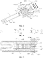
FIG. 1 illustrates a schematic structural diagram of an electrolytic assembly according to a first implementation of the application, here the electrolytic assembly includes an electrode according to a first embodiment. -
FIG. 2 illustrates a schematic diagram of the structure as shown inFIG. 1 from another perspective. -
FIG. 3 illustrates a schematic exploded diagram of the structure as shown inFIG. 1 . -
FIG. 4 illustrates a schematic diagram of the structure as shown inFIG. 2 from another perspective. -
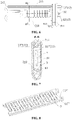
FIG. 5 illustrates a cross-sectional view along the A-A direction ofFIG. 4 . -
FIG. 6 illustrates a schematic diagram of the structure as shown inFIG. 1 from yet another perspective. -
FIG. 7 illustrates a cross-sectional view along the B-B direction ofFIG. 6 . -
FIG. 8 illustrates a schematic structural diagram of the electrode inFIG. 1 assembling with a separation pad. -
FIG. 9 illustrates an exploded diagram of the structure as shown inFIG. 8 . -
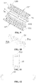
FIG. 10 illustrates a schematic structural diagram of a first insulator according to an embodiment of the application. -
FIG. 11 illustrates a schematic diagram of the structure as shown inFIG. 10 from another perspective. -
FIG. 12 illustrates a schematic structural diagram of a fastener according to an embodiment of the application. -
FIG. 13 illustrates a schematic structural diagram of a separation pad according to an embodiment of the application. -
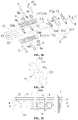
FIG. 14 illustrates a schematic structural diagram of an electrolytic assembly according to a first implementation of the application, here the electrolytic assembly includes an electrode according to a second embodiment. -
FIG. 15 illustrates a schematic exploded diagram of the electrode inFIG. 14 . -
FIG. 16 illustrates a schematic assembling diagram of the structure as shown inFIG. 15 . -
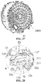
FIG. 17 illustrates a schematic structural diagram of an electrolytic assembly according to a second implementation of the application. -
FIG. 18 illustrates a schematic exploded diagram of the structure as shown inFIG. 17 . -
FIG. 19 illustrates a schematic structural diagram of a second insulator according to an embodiment of the application. -
FIG. 20 illustrates a schematic diagram of the structure as shown inFIG. 17 from another perspective. -
FIG. 21 illustrates a schematic diagram along the F-F direction ofFIG. 20 . -
FIG. 22 illustrates a schematic enlarged diagram of part E inFIG. 21 . -
FIG. 23 illustrates a schematic structural diagram of an electrolytic assembly according to a third implementation of the application, here a buckle, an insulated limiting member and a second fastener are omitted. -
FIG. 24 illustrates a schematic structural diagram of an electrode in the structure as shown inFIG. 23 . -
FIG. 25 illustrates part of a schematic structural diagram of a laundry treatment apparatus according to an embodiment of the application, here the laundry treatment apparatus is provided with the electrolytic assembly according to the first implementation. -
FIG. 26 illustrates a schematic enlarged diagram of part C inFIG. 24 . -
FIG. 27 illustrates a schematic diagram of the structure as shown inFIG. 24 from another perspective. -
FIG. 28 illustrates a schematic enlarged diagram of part D inFIG. 27 . - It should be noted that embodiments of the application and technical features in the embodiments may be combined with each other without conflict, and detailed descriptions in a specific implementation should be understood as an explanation of an objective of the application and should not be taken as unduly limitations of the application.
- During describing the application, orientation or position relationships indicated by terms "top" and "bottom" are based on orientation or position relationships as shown in
FIG. 4 , and it should be understood that the orientation terms are intended only to conveniently describe the application and simplify descriptions, rather than to indicate or imply that devices or components indicated by them must be in specific orientations or structured and operated in specific orientations, and thus should not be understood as limitations of the application. - In the embodiments, a thickness direction of an electrode is consistent with a direction indicated by "top" and "bottom" shown in
FIG. 4 . - The embodiments of the application provide an
electrolytic assembly 1000, referring toFIGS. 1 and 2 , theelectrolytic assembly 1000 includes: an electrolytic device, including anelectrode 11; aheating member 2; and a mountingdevice 3, to which at least one of the electrolytic device or theheating member 2 is connected, and theelectrode 11 and theheating member 2 are located on the same side of the mountingdevice 3. - The
electrolytic assembly 1000 according to the embodiments of the application may generate ·OH having a strong oxidization activity by electrolyzing water by means of the electrolytic device to perform sterilization and disinfection, and may further heat a liquid to a required temperature by means of theheating member 2. The mountingdevice 3 integrates theheating member 2 and the electrolytic device together, to facilitate more compact structural arrangement of theheating member 2 and the electrolytic device on one hand, and facilitate assembly/disassembly of the whole electrolytic assembly on the other hand, to facilitate updating and replacement of a product. Specifically, theelectrolytic assembly 1000 applied to the laundry treatment apparatus is taken as an example, when an existing laundry treatment apparatus is provided with a heating member but is not provided with an electrolytic device, in case that the electrolytic device needs to be added for sterilization and disinfection to improve performance of the product, the existing heating member may be detached, then theelectrolytic assembly 1000 provided by the application may be mounted at an original position where the heating member is mounted, therefore the laundry treatment apparatus may be upgraded and replaced in case that other mounting structures of the laundry treatment apparatus are basically not changed, providing good interchangeability and low production cost. - There are many cases for at least one of the electrolytic device or the
heating member 2 to be connected to the mounting device 3: in the first case, the electrolytic device is connected to the mountingdevice 3, and theheating member 2 is connected to the electrolytic device, that is, theheating member 2 is indirectly connected to the mountingdevice 3 through the electrolytic device; in the second case, theheating member 2 is connected to the mountingdevice 3, theheating member 2 is connected to the electrolytic device, and the electrolytic device is indirectly connected to the mounting device through theheating member 2; and in the third case, each of the electrolytic device and theheating member 2 is connected to the mountingdevice 3. - The
electrode 11 and theheating member 2 are located on the same side of the mountingdevice 3, which means that most of the structure, with a heating function, of theheating member 2 and theelectrode 11 are located on the same side of the mountingdevice 3. - In an embodiment, the electrolytic device includes a
conductive connector 12 in conductive connection with theelectrode 11, the mountingdevice 3 has formed therein a first mounting hole (not shown in the figure) penetrating it, and theconductive connector 12 is hermetically arranged in the first mounting hole in a penetrating manner, and water leakage may be avoided at the first mounting hole. - In an embodiment, the mounting
device 3 has formed therein a second mounting hole (not shown in the figure) penetrating it, and an end of theheating member 2 is hermetically arranged in the second mounting hole in a penetrating manner, and water leakage may be avoided at the second mounting hole. - It may be understood that in an embodiment, only the first mounting hole as described above is formed in the mounting
device 3, the second mounting hole is not formed; and in another embodiment, the mountingdevice 3 has both the first mounting hole and the second mounting hole, that is, each of the electrolytic device and theheating member 2 is connected to the mountingdevice 3. - It may be understood that the
electrode 11 includes a cathode 11' and ananode 11", theconductive connector 12 includes a cathode conductive connector 12' in conductive connection with the cathode 11' and an anodeconductive connector 12" in conductive connection with theanode 11", and theelectrode 11 is connected with a power supply through theconductive connector 12. It may be understood that the cathode 11' and theanode 11" are spaced apart from each other, i.e., the cathode 11' and theanode 11" do not contact with each other at any position, and guaranteeing normal operation of the electrolytic device. It may be understood that referring toFIG. 28 , in order to facilitate wiring of theconductive connector 12 to the power supply, afirst terminal 12a may be fastened to an end of theconductive connector 12 by welding or the like, for example, theconductive connector 12 is fastened to thefirst terminal 12a after penetrating the first mounting hole. - The
heating member 2 may be an electric heating tube, such as a glass heating tube, a stainless steel heating tube, a quartz heating tube, a ceramic heating tube or the like. Theheating member 2 may be made into different shapes. - In an embodiment, referring to
FIGS. 1-3 andFIG. 17 , theheating member 2 includes afirst rod 210, asecond rod 211, and atransition body 212 connected between thefirst rod 210 and thesecond rod 211, a gap is formed between thefirst rod 210 and thesecond rod 211, theelectrode 11 is located between thefirst rod 210 and thesecond rod 211, i.e., theelectrode 11 is located in the gap, therefore on one hand, thefirst rod 210 and thesecond rod 211 may be kept at a distance from each other, and the heating area is increased, and on the other hand, an accommodating space may be provided for theelectrode 11, and theelectrolytic assembly 1000 may be more compact in structure. - The
first rod 210, thesecond rod 211 and thetransition body 212 may be integrally formed. Thetransition body 212 may be made in various desired shapes. - It may be understood that in order to facilitate wiring, referring to
FIG. 28 , asecond terminal 22a may be fastened to an end of theheating member 2 by welding or the like. Specifically, an end of theheating member 2 is fastened to thesecond terminal 22a after penetrating the second mounting hole. - In some embodiments, the
heating member 2 itself may have a temperature control function, for example, a bimetallic strip is placed in the heating tube, the bimetallic strip is formed by combining two metallic strips made of different materials together through a special process, the bimetallic strip deforms according to temperature variations due to different expansion coefficients when the temperature changes, a contact switch is formed in the heating tube by using the bimetallic strip, and the contact switch may be automatically switched off to control the temperature after the temperature is reached. - In other embodiments, a temperature control structure may be additionally arranged outside of the
heating member 2 to control the heating temperature. For example, in the embodiment of the application, referring toFIGS. 1, 2 and4 , theelectrolytic assembly 1000 includes atemperature controller 4, the mountingdevice 3 has formed therein a third mounting hole (not shown in the figure) penetrating it, thetemperature controller 4 is hermetically arranged in the third mounting hole in a penetrating manner, and water leakage may be avoided at the third mounting hole, and an end, configured to measure temperature, of thetemperature controller 4 is located on a side, facing the electrode, of the mountingdevice 3. Thetemperature controller 4 is also integrally mounted on the mountingdevice 3, to improve the integration level of theelectrolytic assembly 1000 and reduce the mounting difficulty. The type of thetemperature controller 4 is not limited. - The electrolytic assembly according to three specific implementations of the application will be described below with reference to the drawings.
-
FIGS. 1-16 illustrate a schematic structural diagram of an electrolytic assembly according to a first implementation of the application. - In an embodiment, the
electrolytic assembly 1000 further includes afirst fastener 61 connecting theelectrode 11 to theheating member 2, and thefirst fastener 61 fixedly connects theelectrode 11 to theheating member 2 to enhance a structural strength between theelectrode 11 and theheating member 2. Specifically, theelectrode 11 is mounted on the mountingdevice 3 through theconductive connector 12, theelectrode 11 may be in a cantilever state, and force bearing condition of theelectrode 11 may be improved through thefirst fastener 61 and theheating member 2, working life of theelectrolytic assembly 1000 is prolonged, and working reliability of theelectrolytic assembly 1000 is improved. The specific mechanism of thefirst fastener 61 is not limited. - Furthermore, in order to prevent the
electrode 11 from shaking under an external force to impact theheating member 2, in an embodiment, referring toFIG. 2 , theelectrolytic assembly 1000 includes afirst insulator 51 and thefirst fastener 61, thefirst insulator 51 is arranged between thefirst rod 210 and thesecond rod 211, and referring toFIG. 10 , a first throughhole 51b is formed in thefirst insulator 51, theelectrode 11 is arranged in the first throughhole 51b in a penetrating mode, that is, thefirst insulator 51 is mounted to sleeve theelectrode 11, therefore theelectrode 11 may be electrically insulated from thefirst rod 210 and thesecond rod 211. Referring toFIG. 12 , thefirst fastener 61 is approximately ringshaped, and referring toFIG. 2 , thefirst fastener 61 surrounds outer surfaces of thefirst rod 210, thesecond rod 211 and thefirst insulator 51. Theelectrode 11, thefirst rod 210 and thesecond rod 211 are bound together by thefirst fastener 61, and preventing thefirst insulator 51 from separating from theelectrode 11 and theheating member 2. - The
first insulator 51 may be made of a material having a damping property, such as rubber, silica gel or the like. - The
first fastener 61 may be an iron wire, a strap or the like. - In order to facilitate limiting the position of the
first fastener 61, in an embodiment, referring toFIGS. 10 and 11 , at least one of a top surface or a bottom surface of thefirst insulator 51 is formed with afirst groove 51a in which a part of thefirst fastener 61 is located, therefore thefirst groove 51a forms a limiting stop of thefirst fastener 61 to prevent thefirst fastener 61 from separating from thefirst insulator 51. - The structure of the
electrode 11 is not limited. - The
electrode 11 includes at least one layer ofelectrode units 11‴, and each layer ofelectrode units 11‴ includes acathode sub-member 110 and ananode sub-member 111. For example, in an embodiment, when theelectrode 11 includes multiple layers ofelectrode units 11‴, referring toFIGS. 1 to 9 , thecathode sub-members 110 in the multiple layers ofelectrode units 11‴ constitute the cathode 11' together, and theanode sub-members 111 in the multiple layers ofelectrode units 11‴ constitute theanode 11". In another embodiment, when theelectrode 11 only includes one layer ofelectrode units 11‴, referring toFIGS. 14 to 16 , thecathode sub-member 110 is the cathode, and theanode sub-member 111 is the anode. - In some embodiments, referring to
FIG. 3 , thecathode sub-member 110 includes afirst support 1102 and at least one first comb-shapedtooth 1101 extending from thefirst support 1102 along a direction away from thefirst support 1102; and theanode sub-member 111 includes asecond support 1112 and at least one second comb-shapedtooth 1111 extending from thesecond support 1112 along a direction away from thesecond support 1112; and the first comb-shapedtooth 1101 and the second comb-shapedtooth 1111 are alternately arranged at an interval, that is, the first comb-shapedtooth 1101 and the second comb-shapedtooth 1111 are formed in an interdigital structure. - According to the electrode device provided by the embodiment of the application, the first comb-shaped
tooth 1101 and the second comb-shapedtooth 1111 are formed in an interdigital structure, and on one hand, theelectrode unit 11‴ has a larger working surface area, the electrolytic efficiency of the electrolytic device is improved, and on the other hand, theelectrode unit 11‴ only needs to occupy a smaller space, therefore the electrolytic device may be compact in structure. In another aspect, the electrolytic device applied to the laundry treatment apparatus is taken as an example, during washing laundries, fluffs on laundries are mixed into water, since a gap between the first comb-shapedtooth 1101 and the second comb-shapedtooth 1111 is a long and narrow gap, fluffs may easily pass through the long and narrow gap, that is, fluffs are not easy to block the electrolytic device, and the service life of the electrolytic device may be prolonged. In addition, when the electrolytic device bears an external force approximately perpendicular to the plane or curved surface, since thecathode sub-member 110 and theanode sub-member 111 do not overlap, thecathode sub-member 110 and theanode sub-member 111 do not contact with each other even if thecathode sub-member 110 and theanode sub-member 111 displace under an action of the external force, and thus a short circuit caused by contact between thecathode sub-member 110 and theanode sub-member 111 may be effectively prevented. According to this design, a thickness of the assembly of thecathode sub-member 110 and theanode sub-member 111 may be designed to be very small, which is beneficial for the light and thin design of the electrolytic device, and the electrolytic device may be installed in a narrow space, for example, between an inner cylinder and an outer cylinder of the laundry treatment apparatus. - It should be noted that in the laundry treatment apparatus, life of the electrolytic device needs to match with designed service life of the laundry treatment apparatus, and when the life of the electrolytic device is substantially shorter than the designed service life of the laundry treatment apparatus, the laundry treatment apparatus may be scrapped in advance and consumers' benefits are impaired. According to the electrolytic device provided by the embodiment of the application, it may be guaranteed well that impurities such as fluffs or the like do not block the
electrode 11, and thus the life of the electrolytic device may reach the designed service life of the laundry treatment apparatus. - The specific structural form of the first comb-shaped
tooth 1101 is not limited, and the first comb-shapedtooth 1101 may be formed in a sheet shape, a column shape, a strip shape or the like. Similarly, the specific structural form of the second comb-shapedtooth 1111 is not limited, and the second comb-shapedtooth 1111 may be formed in a sheet shape, a column shape, a strip shape or the like. The cross section of the column shape is not limited in shape and may be circular, polygonal or the like. - In the embodiment of the application, referring to
FIG. 2 , the structure of the first comb-shapedtooth 1101 is substantially the same as that of the second comb-shapedtooth 1111, the first comb-shapedtooth 1101 is substantially parallel to the second comb-shapedtooth 1111, and thefirst support 1102 is substantially parallel to thesecond support 1112, and the electrolytic device is more compact in structure and neat and attractive in appearance. - In another embodiment, referring to
FIGS. 14-16 , the first comb-shapedtooth 1101 includes afirst sub-tooth 11011 and asecond sub-tooth 11012 which are arranged at an interval along a thickness direction of the cathode 11', that is, thefirst support 1102 has a thickness, and thefirst sub-tooth 11011 and thesecond sub-tooth 11012 share the samefirst support 1102; and the second comb-shapedtooth 1111 includes a third sub-tooth 11111 and afourth sub-tooth 11112 which are arranged at an interval along a thickness direction of theanode 11", that is, thesecond support 1112 has a thickness, and the third sub-tooth 11111 and thefourth sub-tooth 11112 share the samesecond support 1112. Thus, the electrolytic area may be increased, and the electrolytic efficiency may be improved. - Referring to
FIG. 9 , theelectrode units 11‴ have multiple layers, the multiple layers ofelectrode units 11‴ are stacked together to form theelectrode 11, thecathode sub-members 110 of the multiple layers ofelectrode units 11‴ may be fastened into a whole component through a fastener, and the anode sub-members 111 of the multiple layers ofelectrode units 11‴ may be fastened into a whole component through a fastener. Furthermore, referring toFIG. 9 , theelectrolytic assembly 1000 includesseparation pads 7 which are arranged between adjacent two of theelectrode units 11‴. The number of theseparation pads 7 depends on the number of theelectrode units 11‴. - It should be noted that
multiple cathode sub-members 110 are electrically connected to the cathode conductive connector 12', andmultiple anode sub-members 111 are electrically connected to the anodeconductive connector 12". The cathode sub-members 110 and the cathode conductive connector 12' may be connected by welding, or may be connected by screws, bolts or the like. Similarly, the anode sub-members 111 and the anodeconductive connector 12" may be connected by welding, or may be connected by screws, bolts or the like. -
Multiple electrode units 11‴ are stacked to form theelectrode 11, on one hand, the electrolytic area may be effectively increased, the electrolytic efficiency may be improved, and on the other hand, the manufacturing difficulty is reduced. Specifically, each of theelectrode units 11‴ is approximately formed in a flat structure, thus the structure is simple, machining and manufacturing cost thereof is low, manufacturing thereof is easy, standardized mass production thereof may be realized, and during assembly, the number of theelectrode units 11‴ to be stacked may be determined according to the needs of applications. - Furthermore, in order to enhance fluidity of liquid around the
electrode 11, and to facilitate that tiny bubbles on a surface of theelectrode 11 to timely separate from the surface of theelectrode 11 and diffuse into the liquid, in an embodiment, referring toFIG. 13 , each of theseparation pads 7 has formed therein first throughholes 7a penetrating theseparation pad 7 along a thickness direction thereof, and the liquid may flow amongmultiple electrode units 11‴ and scour the surface of theelectrode 11 to timely take away tiny bubbles on the surface of theelectrode 11. - In an embodiment, with further reference to
FIG. 13 , aprotrusion 71 is formed on a surface of each of theseparation pads 7, and there may be one ormore protrusions 71. Theprotrusion 71 extends into a space between thecathode sub-member 110 and theanode sub-member 111 of theelectrode unit 11‴ located on the same layer. The position of theprotrusion 71 is not limited, for example, theprotrusion 71 may extend into the gap between the first comb-shapedtooth 1101 and the second comb-shapedtooth 1111, therefore a short circuit caused by contact between the first comb-shapedtooth 1101 and the second comb-shapedtooth 1111 man be prevented; theprotrusion 71 may also extend into a gap between an end of the first comb-shapedtooth 1101 and thesecond support 1112, and a short circuit caused by contact between the first comb-shapedtooth 1101 and thesecond support 1112 may be prevented; and theprotrusion 71 may also extend into a gap between an end of the second comb-shapedtooth 1111 and thefirst support 1102, and a short circuit caused by contact between the second comb-shapedtooth 1111 and thefirst support 1102 may be prevented. In the case that there aremultiple protrusions 71, it is also possible to arrange theprotrusion 71 at each of the above positions. - Referring to
FIGS. 1 and 2 , in an embodiment, the mountingdevice 3 includes aconnector 32 and amain body 31 has formed therein the first mounting hole, the second mounting hole, the third mounting hole and a connecting hole penetrating it, and each of the first mounting holes, the second mounting holes, the third mounting hole and the connecting hole penetrates from one side of themain body 31 to the other side of themain body 31. Theconnector 32 is hermetically arranged in the connecting hole in a penetrating manner. - It should be noted that in the implementation, there are two first mounting holes, the cathode conductive connector 12' is arranged in one of the first mounting holes in a penetrating manner, and the anode
conductive connector 12" is arranged in the other of the first mounting holes in a penetrating manner. It should be noted that there are two second mounting holes, thefirst rod 210 is arranged in one of the second mounting holes in a penetrating manner, and thesecond rod 211 is arranged in the other of the second mounting holes in a penetrating manner. - Furthermore, referring to
FIG. 3 , themain body 31 includes afirst mounting plate 310, asecond mounting plate 311 and anelastic body 312. Thefirst mounting plate 310 is arranged on a side, facing theelectrode 11, of theelastic body 312, thesecond mounting plate 311 is arranged on a side, away from theelectrode 11, of theelastic body 312, and theelastic body 312 is clamped between the first mountingplate 310 and thesecond mounting plate 311. The first mounting hole, the second mounting hole, the third mounting hole and the connecting hole penetrate the first mountingplate 310, thesecond mounting plate 311 and theelastic body 312 respectively. - In the embodiment of the application, the
connector 32 may be a connection structure formed by a bolt and a nut together. - The
first mounting plate 310 and thesecond mounting plate 311 are tensioned through theconnector 32, and theelastic body 312 deforms by bearing a force, an inner wall of the first mounting hole abuts against theconductive connector 12 in a sealing manner, an inner wall of the second mounting hole abuts against theheating member 2 in a sealing manner, and theconnector 32 abuts against an inner wall of the connecting hole in a sealing manner. - In order to facilitate locating the
elastic body 312 during assembly, in an embodiment, referring toFIGS. 1 and4 , an abuttingsurface 312a is formed along a circumferential direction of theelastic body 312. -
FIGS. 17-22 illustrate a schematic structural diagram of an electrolytic assembly according to a second implementation of the application. - Referring to
FIG. 18 , theelectrode 11 includes a cathode 11' and ananode 11", each of the cathode 11' and theanode 11" is formed in a plate shape, and the cathode 11' and theanode 11" are arranged in a stack. Specifically, in an embodiment, thefirst rod 210 and thesecond rod 211 are arranged to be substantially parallel to each other, and a direction of stacking the cathode 11' and theanode 11" is perpendicular to a plane where thefirst rod 210 and thesecond rod 211 are located, and thus theelectrolytic assembly 1000 is more compact in structure. - In an embodiment, with further reference to
FIG. 18 , theanode 11" is provided with second throughholes 11c penetrating theanode 11" along a thickness direction thereof, and liquid flow may flow from one side of theanode 11" to the other side of theanode 11" through the second throughholes 11c, and fluidity of water flow may be enhanced, and the water flow may take away microbubbles on the surface of theanode 11" in time to prevent the microbubbles from accumulating to become large. In an embodiment, with further reference toFIG. 18 , the cathode 11' is provided with third throughholes 11d penetrating the cathode 11' in a thickness direction thereof, and liquid flow may flow from one side of the cathode 11' to the other side of the cathode 11' through the third throughholes 11d, and fluidity of water flow may be enhanced, and the water flow may take away microbubbles on the surface of the cathode 11' in time to prevent the microbubbles from accumulating to become large. - In an embodiment, referring to
FIG. 18 , theelectrolytic assembly 1000 includessecond insulators 52, and further referring toFIG. 22 , at least a part of each of thesecond insulators 52 is clamped between the cathode 11' and theanode 11", and a short circuit caused by contact between the cathode 11' and theanode 11" may be avoided, and reliability of the electrolytic device is improved. - The shape of the
second insulator 52 is not limited, as long as the cathode 11' and theanode 11" may be brought into contact effectively. For example, exemplarily, referring toFIG. 19 , each of thesecond insulators 52 includes abase 521 andcolumns 522 protruding out of a surface of thebase 521, and further referring toFIG. 22 , theanode 11" is provided with throughholes 11a, thebase 522 is clamped between the cathode 11' and theanode 11", and each of thecolumns 522 is arranged in a respective one of the throughholes 11a in a penetrating manner. According to thesecond insulator 52 of the embodiment, the cathode 11' and theanode 11" may be effectively isolated through thebase 521, and theanode 11" may be located through thecolumn 522. - There may be one or
more columns 522. - The
second insulator 52 may be made of a material having a damping property, such as rubber, silica gel or the like. - In an embodiment, referring to
FIG. 18 , theelectrolytic assembly 1000 further includes abuckle 8 andsecond fasteners 62, and thebuckle 8 and theelectrode 11 are fixedly connected by thesecond fasteners 62 and thebuckle 8. Theelectrode 11 may be attached to theheating member 2 through thesecond fasteners 62 and thebuckle 8. Specifically, theelectrode 11 is mounted on the mountingdevice 3 through theconductive connector 12, theelectrode 11 may be in a cantilever state, and force bearing condition of theelectrode 11 may be improved through theheating member 2 after attaching theelectrode 11 to theheating member 2, working life of theelectrolytic assembly 1000 may be prolonged, and working reliability of theelectrolytic assembly 1000 may be improved. - With further reference to
FIG. 8 , thebuckle 8 includes a connectingsection 81 located between thefirst rod 210 and thesecond rod 211 and snappingsections 82 located at two opposite ends of the connectingsection 81, one of the snappingsections 82 is snapped on thefirst rod 210, specifically, snapped to a side, away from thesecond rod 211, of thefirst rod 210. The other of the snappingsections 82 is snapped on thesecond rod 211, specifically, snapped to a side, away from thefirst rod 210, of thesecond rod 211. Thebuckle 8 is snapped on thefirst rod 210 and thesecond rod 211 through the snappingsections 82 at two ends, and thebuckle 8 is prevented from moving relative to theheating member 2. - The
buckle 8 may be a metal member and the snappingsections 82 at two ends have greater structural strength and greater elastic deformation. - To enhance connection reliability, the
buckle 8 as described above may be used in pairs. Specifically, thebuckles 8 are arranged on two opposite sides along a stacking direction of the cathode 11' and theanode 11", the cathode 11' and theanode 11" are clamped between two of thebuckles 8, and the twobuckles 8 and theelectrode 11 are fixedly connected through thesecond fasteners 62. Specifically, in an embodiment, thesecond fastener 62 is a bolt which may securely lock the cathode 11' and theanode 11" between the twobuckles 8. - In an embodiment,
multiple buckles 8 are present, and arranged at intervals along a length direction of at least one of thefirst rod 210 or thesecond rod 211. It may be understood thatmultiple buckles 8 may be only present on a top side of the electrode; ormultiple buckles 8 may be only present on a bottom side of the electrode; ormultiple fasteners 8 may be present on both the top side and the bottom side of the electrode. That is, in the embodiment, multiple pairs ofbuckles 8 as described above are arranged at intervals along the length direction of at least one of thefirst rod 210 or thesecond rod 211, one pair of buckles includes one buckle on the top side of the electrode and one buckle on the bottom side of the electrode, and the two buckles are used in pair. - In an embodiment, an end face of each of the
columns 522 protrudes out of a surface of theanode 11", and abuts against the connectingsection 81 and an interval space is formed between the connectingsection 81 and theanode 11", and the interval space may insulate and separate the connecting section and theanode 11" and electrochemical corrosion of theanode 11" may be prevented. - Furthermore, referring to
FIG. 22 , a first connectinghole 52a penetrating each of thecolumns 522 and thebase 521 is formed in thesecond insulator 52, second connectingholes 8a are formed in the connectingsection 81, third connectingholes 11b are formed in thecathode 11", and each of thesecond fasteners 62 is arranged in a respective one of the first connectingholes 52a, the second connectingholes 8a and the third connectingholes 11b in a penetrating manner, that is, thesecond fastener 62 does not contact with theanode 11", and electrochemical corrosion of theanode 11" may be prevented. - In an embodiment of the application, the
buckle 8 may be made of a metal. Specifically, in order to prevent theanode 11" from being in conductive contact with theheating member 2 or thesecond fastener 62, in an embodiment of the application, theanode 11" is provided with a throughhole 11a, thecolumn 522 is arranged in the throughhole 11a of theanode 11" in a penetrating manner, theanode 11" may be electrically insulated from thecathode 11", thebuckle 8 and thesecond fastener 62 under an action of thesecond insulator 52, and electrochemical corrosion of theanode 11" may be prevented. - In an embodiment, referring to
FIG. 18 , theelectrolytic assembly 1000 further includes insulated limitingmembers 9 clamped in the interval space between the connectingsection 81 and theanode 11", and capable of limiting theelectrode 11 to prevent theelectrode 11 from moving in the stacking direction. - In an embodiment, referring to
FIGS. 18 and22 , at least one second throughhole 9b is formed in each of the insulated limitingmembers 9, and each of thecolumns 522 is arranged in a respective one of the second throughholes 9b in a penetrating mode. A locating effect may be achieved on insulated limitingmember 9 through thecolumn 522, and the insulated limitingmember 9 may be rapidly located and mounted during assembly. - The number of the
column 522 is greater than or equal to that of the second throughhole 9b. In an embodiment,multiple columns 522 are present, and arranged at intervals along an extending direction of the connectingsection 81. There may be one or more second throughholes 9b in the insulated limitingmember 9, and when there are multiple second throughholes 9b, a respective onecolumn 522 is arranged in each of the second throughholes 9b in a penetrating mode. It may be understood that whenmultiple columns 522 are arranged, there may be one or moresecond fasteners 62, that is, when at least onesecond fastener 62 meets a need for a fixed connection, nosecond fasteners 62 may be placed in somecolumns 522. - In another embodiment, referring to
FIG. 18 , each of the insulated limitingmembers 9 has formed therein a second throughhole 9b in which a respective one of thecolumns 522 is arranged in a penetrating manner, one of the insulated limitingmembers 9 is arranged between two of thecolumns 522, that is, there are at least threecolumns 522, and each of the insulated limitingmembers 9 is formed withopen notches 9c at two opposite ends thereof along the extending direction of the connectingsection 81, and each of theopen notches 9c is matched with thecorresponding column 522. Through theopen notches 9c at two ends, the insulated limitingmember 9 may be well located, and thus the insulated limitingmember 9 is prevented from rotating. In the embodiment, a size of the insulated limitingmember 9 may be reduced, and the electrolytic assembly is simple in structure. - In an embodiment, with further reference to
FIG. 18 , each of the insulated limitingmembers 9 is provided with asecond groove 9a extending along an extending direction of the connectingsection 81, and a part of the connectingsection 81 is located in thesecond groove 9a. Thesecond groove 9a plays a role of locating the connectingsection 81 in a direction perpendicular to the extending direction of the connectingsection 81, and thus the connectingsection 81 is prevented from sliding relative to the insulated limitingmember 9. - In the implementation, the structure of the mounting device is substantially the same as that in the first implementation, except that in the implementation, there is one first mounting hole, and the conductive connector of the anode and the conductive connector of the cathode share the one first mounting hole. It should be noted that the conductive connector of the cathode and the conductive connector of the anode remain electrically insulated even if they are arranged in the same first mounting hole.
- Referring to
FIGS. 23 and24 , the structure in the implementation is substantially the same as that in the second implementation, except that the structural form of the electrode is different. Specifically, referring toFIG. 24 , in the implementation, each of the cathode 11' and theanode 11" is formed in a net-shaped structure, that is, density of the third throughholes 11d in the cathode 11' is large and the cathode 11' is formed in a net-shaped structure as a whole, and density of the second throughholes 11c in theanode 11" is large and theanode 11" is in is formed in a net-shaped structure as a whole. - Referring to
FIGS. 25-28 , a second aspect of the embodiments of the application provides a laundry treatment apparatus including an inner cylinder (not shown in the figure), anouter cylinder 2000, and theelectrolytic assembly 1000 of any one of the above descriptions, here the inner cylinder is arranged in a rotatable manner in theouter cylinder 2000, and theouter cylinder 2000 has formed therein an avoiding opening (not shown in the figure), and theelectrode 11 and theheating member 2 are arranged between theouter cylinder 2000 and the inner cylinder, and the mountingdevice 3 seals the avoiding opening. - According to the laundry treatment device disclosed by the embodiment of the application, during working, when the outer cylinder is filled with water, the electrolytic device is activated and may generate hydroxyl free radicals (·OH) with a strong oxidation activity, ·OH has an extremely high oxidation potential (2.80 eV) and extremely strong oxidation capacity, may generate a rapid chain reaction with most of organic pollutants, may realize sterilization and disinfection at a low temperature and does not damage laundries, a part of ·OH react with chlorine water in tap water to generate active chlorine, and the active chlorine may exist for a long time and has a long-term bacteriostatic effect; and the electrolytic device generates a large amount of ·OH to oxidize and destroy chromophoric groups of dye molecules of colored laundries dissociated into water during washing to decolorize dyes, and the dissociated dyes are prevented from staining light-color laundries to induce cross-color, and the dye molecules are decomposed into harmless carbon dioxide, water and inorganic salt through continuous reaction. Furthermore, a large number of hydrogen microbubbles may be generated by the
electrode 11, since a diameter of each of the microbubbles is small, generally smaller than 50 um, the microbubbles may well enter an interior of laundry fibers during washing, circulating flushing of the microbubbles is continuously generated through blasting, adsorption and floating effects of the microbubbles, to assist a detergent to thoroughly remove sebum, grease, tiny dust and other dirt accumulated in the laundry fibers, and thus the washing effect may be improved. - It should be noted that the laundry treatment apparatus according to the embodiment of the application may be a washing machine, a dewatering machine, or another type of apparatus, no limitation is made thereto. It may be understood that the washing machine may be a pulsator washing machine, or may be a drum washing machine, or may be a washing machine of another structural type.
- In order to facilitate the support of the
heating member 2, in an embodiment of the application, referring toFIG. 26 , the laundry treatment apparatus includes a mountingsupport 3000 connected to an inner side of theouter cylinder 2000 and supporting theheating member 2. The mountingsupport 3000 plays a supporting role on theheating member 2, specifically, the mountingsupport 3000 and the mountingdevice 3 support theheating member 2 together, and the support of theheating member 2 is avoided to become a cantilever, and force bearing condition of theheating member 2 may be improved. The mountingsupport 3000 may be any suitable structure. - The assembly of the
electrolytic assembly 1000 and theouter cylinder 2000 according to a specific embodiment of the application will be described below by example of the laundry treatment apparatus being a drum washing machine. An axial side of theouter cylinder 2000 is provided with an opening, and the other side, opposite to the opening, of the outer cylinder is a closed end. The embodiment of the application is described by example of the avoiding opening being formed at the closed end, and it may be understood that the avoiding opening may also be formed in the circumference, following the rotation direction, of theouter cylinder 2000. - Before assembly, the
heating member 2, the mountingdevice 3 and the electrolytic device may form an integral structure in advance, and during assembly, the integral structure is placed into the avoiding opening from the outer side of theouter cylinder 2000, theelastic body 312 abuts against the periphery of the avoiding opening in a sealing manner, the electrolytic assembly is pushed inwards until the abuttingface 312a of theelastic body 312 abuts against the outer surface of the outer cylinder, therefore, rapid and accurate locating of the electrolytic assembly is facilitated. And then, theconnector 32 is tensioned, theelastic body 312 generates elastic deformation, the parts, located around the avoiding opening in the inner side of the outer cylinder and around the avoiding opening in the outer side of the outer cylinder, of theelastic body 312 are bulged towards the periphery, then theelastic body 312 is clamped on the outer cylinder from both the inner direction and the outer direction, and quick sealed mounting may be realized simply and conveniently. - In the embodiment, a modular assembly is adopted, and thus the assembly is simple and efficient.
- The embodiments/implementations provided in the application may be combined with each other without conflict.
- The foregoing is merely preferred embodiments of the application and is not intended to limit the application, and various modifications and variations of the application may be available for those skilled in the art. Any modifications, equivalents, improvements, etc., made within the spirit and principles of the application are intended to be included within the protection scope of the application.
Claims (30)
- An electrolytic assembly, comprising:an electrolytic device, comprising an electrode;a heating member; anda mounting device, to which at least one of the electrolytic device or the heating member is connected, and the electrode and the heating member are located on the same side of the mounting device.
- The electrolytic assembly of claim 1, wherein the electrolytic device comprises a conductive connector in conductive connection with the electrode, the mounting device has formed therein a first mounting hole penetrating it, and the conductive connector is hermetically arranged in the first mounting hole in a penetrating manner.
- The electrolytic assembly of claim 2, wherein the mounting device has formed therein a second mounting hole penetrating it, and an end of the heating member is hermetically arranged in the second mounting hole in a penetrating manner.
- The electrolytic assembly of claim 1, comprising a first fastener configured to connect the electrode to the heating member.
- The electrolytic assembly of claim 1, wherein the heating member comprises a first rod and a second rod, and the electrode is located between the first rod and the second rod.
- The electrolytic assembly of claim 5, comprising a first insulator located between the first rod and the second rod and mounted to sleeve the electrode, and a first fastener surrounding outer surfaces of the first rod, the second rod and the first insulator.
- The electrolytic assembly of claim 6, wherein at least one of a top surface or a bottom surface of the first insulator is formed with a first groove in which a part of the first fastener is located.
- The electrolytic assembly of claim 1, wherein the electrode comprises at least one layer of electrode units.
- The electrolytic assembly of claim 8, wherein each of the electrode units comprises a cathode sub-member and an anode sub-member which are arranged at an interval, the cathode sub-member comprises a first support and at least one first comb-shaped tooth extending from the first support along a direction away from the first support; and
the anode sub-member comprises a second support and at least one second comb-shaped tooth extending from the second support along a direction away from the second support; and the first comb-shaped tooth and the second comb-shaped tooth are alternately arranged at an interval. - The electrolytic assembly of claim 9, wherein the first comb-shaped tooth comprises a first sub-tooth and a second sub-tooth which are arranged at an interval along a thickness direction of the cathode sub-member; and the second comb-shaped tooth comprises a third sub-tooth and a fourth sub-tooth which are arranged at an interval along a thickness direction of the anode sub-member.
- The electrolytic assembly of claim 8, wherein the electrode units have a plurality of layers; and the electrolytic assembly comprises separation pads which are arranged between adjacent two of the electrode units.
- The electrolytic assembly of claim 11, wherein each of the separation pads has formed therein first through holes penetrating the separation pad along a thickness direction thereof.
- The electrolytic assembly of claim 11, wherein each of the electrode units comprises a cathode sub-member and an anode sub-member which are arranged at an interval, and a protrusion is formed on a surface of each of the separation pads, and extends into a space between the cathode sub-member and the anode sub-member on the same side of the separation pad.
- The electrolytic assembly of claim 5, comprising second insulators, each of which at least a part is clamped between a cathode and an anode forming the electrode.
- The electrolytic assembly of claim 14, wherein the cathode and the anode are arranged in a stack, each of the second insulators comprises a base clamped between the cathode and the anode and columns protruding out of a surface of the base, the anode is provided with through holes, and each of the columns is arranged in a respective one of the through holes in a penetrating manner.
- The electrolytic assembly of claim 15, comprising buckles and second fasteners, through which the heating member and the electrode are fixedly connected.
- The electrolytic assembly of claim 16, wherein each of the buckles comprises a connecting section located between the first rod and the second rod and snapping sections located at two opposite ends of the connecting section, one of the snapping sections is snapped on the first rod, and the other of the snapping sections is snapped on the second rod.
- The electrolytic assembly of claim 16, wherein a plurality of buckles are present, and arranged at intervals along a length direction of at least one of the first rod or the second rod.
- The electrolytic assembly of claim 16, wherein the buckles are arranged on two opposite sides along a stacking direction of the cathode and the anode, the cathode and the anode are clamped between two of the buckles, and the cathode, the anode and the two of the buckles are fixedly connected through the second fasteners.
- The electrolytic assembly of claim 17, wherein an end face of each of the columns protrudes out of a surface of the anode, and abuts against the connecting section and an interval space is formed between the connecting section and the anode, a first connecting hole penetrating each of the columns and the base is formed in the second insulator, second connecting holes are formed in the connecting section, third connecting holes are formed in the cathode, and each of the second fasteners is arranged in a respective one of the first connecting holes, the second connecting holes and the third connecting holes in a penetrating manner.
- The electrolytic assembly of claim 20, comprising insulated limiting members clamped in the interval space between the connecting section and the anode.
- The electrolytic assembly of claim 21, wherein at least one second through hole is formed in at least one of the insulated limiting members, and each of the columns is arranged in a respective one of the second through holes in a penetrating manner.
- The electrolytic assembly of claim 22, wherein a plurality of columns are present, and arranged at intervals along an extending direction of the connecting section, each of the insulated limiting members has formed therein a second through hole in which a respective one of the columns is arranged in a penetrating manner, one of the insulated limiting members is arranged between two of the columns, and formed with open notches at two opposite ends thereof along the extending direction of the connecting section, and each of the open notches is matched with a respective one of the columns.
- The electrolytic assembly of claim 21, wherein each of the insulated limiting members is provided with a second groove extending along an extending direction of the connecting section, and a part of the connecting section is located in the second groove.
- The electrolytic assembly of any one of claims 14-24, wherein the anode is provided with second through holes penetrating the anode along a thickness direction thereof; and/or, the cathode is provided with third through holes penetrating the cathode along a thickness direction thereof.
- The electrolytic assembly of any one of claims 15-24, wherein the anode is formed in a net-shaped structure, and the cathode is formed in a net-shaped structure.
- The electrolytic assembly of claim 2, comprising a temperature controller, the mounting device has formed therein a third mounting hole penetrating it, the temperature controller is hermetically arranged in the third mounting hole in a penetrating manner, and an end, configured to measure temperature, of the temperature controller is located on a side, facing the electrode, of the mounting device.
- The electrolytic assembly of claim 3, wherein the mounting device comprises a connector and a main body comprising a first mounting plate, a second mounting plate and an elastic body clamped between the first mounting plate and the second mounting plate; the mounting device has formed therein a connecting hole in which the connector is hermetically arranged in a penetrating manner; and the first mounting hole, the second mounting hole and the connecting hole penetrate the first mounting plate, the elastic body and the second mounting plate respectively.
- A laundry treatment apparatus, comprising:an inner cylinder;an outer cylinder, in which the inner cylinder is arranged in a rotatable manner, and having formed therein an avoiding opening; andthe electrolytic assembly of any one of the claims 1-28, having the electrode and the heating member arranged between the outer cylinder and the inner cylinder, and having the mounting device sealing the avoiding opening.
- The laundry treatment apparatus of the claim 29, comprising a mounting support connected to an inner side of the outer cylinder and supporting the heating member.
Applications Claiming Priority (5)
| Application Number | Priority Date | Filing Date | Title |
|---|---|---|---|
| CN201910722803 | 2019-08-06 | ||
| CN201910722785 | 2019-08-06 | ||
| CN201922138237.7U CN211896182U (en) | 2019-08-06 | 2019-12-03 | Electrolytic component and clothes treatment equipment |
| CN201911222522.5A CN110902767B (en) | 2019-08-06 | 2019-12-03 | Electrolytic components and clothing processing equipment |
| PCT/CN2019/130109 WO2021022780A1 (en) | 2019-08-06 | 2019-12-30 | Electrolytic assembly and laundry treatment apparatus |
Publications (3)
| Publication Number | Publication Date |
|---|---|
| EP3998239A1 true EP3998239A1 (en) | 2022-05-18 |
| EP3998239A4 EP3998239A4 (en) | 2022-11-30 |
| EP3998239B1 EP3998239B1 (en) | 2025-03-19 |
Family
ID=69821929
Family Applications (1)
| Application Number | Title | Priority Date | Filing Date |
|---|---|---|---|
| EP19940515.0A Active EP3998239B1 (en) | 2019-08-06 | 2019-12-30 | Electrolytic assembly and laundry treatment apparatus |
Country Status (5)
| Country | Link |
|---|---|
| US (1) | US12091334B2 (en) |
| EP (1) | EP3998239B1 (en) |
| JP (1) | JP7294732B2 (en) |
| CN (5) | CN113548719B (en) |
| WO (1) | WO2021022780A1 (en) |
Families Citing this family (12)
| Publication number | Priority date | Publication date | Assignee | Title |
|---|---|---|---|---|
| CN113548719B (en) * | 2019-08-06 | 2023-08-18 | 无锡小天鹅电器有限公司 | Electrolysis assembly and clothes treatment equipment |
| IT202000017875A1 (en) * | 2020-07-23 | 2022-01-23 | Marco Borgiani | IMMERSION DEVICE FOR SANITIZING WATER |
| CN115726158A (en) * | 2021-08-31 | 2023-03-03 | 无锡小天鹅电器有限公司 | Electrolytic component and clothes treatment equipment |
| CN115897148B (en) * | 2021-09-30 | 2025-10-21 | 无锡小天鹅电器有限公司 | Electrolytic component and clothing processing equipment |
| CN113998759A (en) * | 2021-09-30 | 2022-02-01 | 无锡小天鹅电器有限公司 | Method for manufacturing electrolysis device, electrolysis device and clothes treatment equipment |
| KR102705471B1 (en) * | 2022-05-17 | 2024-09-11 | 주식회사 디에스더블유 | Heating device for clothing management |
| US12264426B2 (en) | 2022-12-21 | 2025-04-01 | Midea Group Co., Ltd. | Laundry washing machine and low profile conductivity sensor therefor |
| CN121754087A (en) * | 2022-12-30 | 2026-03-31 | 湖北美的洗衣机有限公司 | Cleaning base stations, clothing processing equipment and cleaning systems |
| JP2024176533A (en) * | 2023-06-08 | 2024-12-19 | パナソニックIpマネジメント株式会社 | Electrolytic liquid generator |
| WO2025044667A1 (en) * | 2023-08-30 | 2025-03-06 | 无锡小天鹅电器有限公司 | Spray head body device and laundry treatment apparatus |
| IT202300024450A1 (en) * | 2023-11-17 | 2025-05-17 | Borgiani Andrea | SYSTEM FOR THE DETECTION OF ONE OR MORE PHYSICAL QUANTITIES OF THE SERVICE WATER OF A HOUSEHOLD APPLIANCE |
| CN117585744B (en) * | 2023-12-29 | 2026-04-03 | 杭州热威电热科技股份有限公司 | A module integrating sterilization and heating functions and its integration method |
Family Cites Families (53)
| Publication number | Priority date | Publication date | Assignee | Title |
|---|---|---|---|---|
| BE639094A (en) | 1963-10-23 | |||
| US4110191A (en) | 1977-08-16 | 1978-08-29 | Olin Corporation | Separator-electrode unit for electrolytic cells |
| FR2469471A1 (en) | 1979-11-09 | 1981-05-22 | Degremont | ELECTROLYSIS APPARATUS WITH BI-POLAR ELECTRODES IN PARTICULAR FOR THE ELECTROLYSIS OF SALINE SOLUTIONS WITH OBTAINING HYPOCHLORITE |
| IT1177236B (en) | 1983-11-17 | 1987-08-26 | Toyo Soda Mfg Co Ltd | PROCEDURE FOR PRODUCING CAUSTIC ALKALINE AGENTS |
| EP0286093B1 (en) | 1987-04-10 | 1993-06-23 | Mitsubishi Materials Corporation | A method for electrowinning a metal using an electrode unit consisting of assembled anode plates and cathode plates and a frame body for forming such an electrode unit |
| CA2171007C (en) * | 1993-09-06 | 2002-01-15 | Spiro Ross Spiros | Improvements in electrolysis systems |
| JP3060968B2 (en) * | 1996-10-22 | 2000-07-10 | 株式会社村田製作所 | Positive characteristic thermistor and positive characteristic thermistor device |
| JPH10277554A (en) * | 1997-04-09 | 1998-10-20 | Konica Corp | Water treatment apparatus |
| JP2000107090A (en) * | 1998-10-02 | 2000-04-18 | Denaro:Kk | Washing method and device using bactericidal water |
| ATE256768T1 (en) | 1999-05-10 | 2004-01-15 | Ineos Chlor Ltd | ELECTRODE STRUCTURE |
| US6187155B1 (en) | 1999-08-05 | 2001-02-13 | Stuart Energy Systems Inc. | Electrolytic cell separator assembly |
| JP2001286698A (en) * | 2000-04-07 | 2001-10-16 | Sharp Corp | Washing machine |
| AU2002367842A1 (en) * | 2001-10-22 | 2003-11-11 | The C And M Group, Llc | Mediated electrochemical oxidation of organic waste materials |
| JP4107854B2 (en) * | 2002-03-07 | 2008-06-25 | 三洋電機株式会社 | Drum washing machine |
| JP3806662B2 (en) * | 2002-03-27 | 2006-08-09 | 三洋電機株式会社 | Drum washing machine |
| JP4039970B2 (en) * | 2003-03-31 | 2008-01-30 | 三洋電機株式会社 | Electrolytic apparatus and water treatment apparatus using the same |
| JP2004298754A (en) * | 2003-03-31 | 2004-10-28 | Matsushita Electric Ind Co Ltd | Electrolysis apparatus and washing machine equipped with the same |
| US20040206133A1 (en) * | 2003-04-19 | 2004-10-21 | Kyung-Chul Woo | Washing machine |
| TWM248799U (en) | 2003-07-28 | 2004-11-01 | Wen-Shing Shiu | Electrolysis device for washing machine |
| FR2862136B1 (en) * | 2003-11-10 | 2006-02-24 | Brandt Ind | CONDUCTIVITY MEASURING PROBE AND WASHING TANK EQUIPPED WITH THE SAME |
| CN2693802Y (en) * | 2003-11-14 | 2005-04-20 | 海尔集团公司 | Electrolysis unit for washing machine |
| JP4474910B2 (en) * | 2003-12-01 | 2010-06-09 | パナソニック株式会社 | Electrolysis device and washing machine equipped with the same |
| CN2712972Y (en) * | 2003-12-31 | 2005-07-27 | 钱光万 | Washing device without detergent and recycle water |
| US20050279141A1 (en) * | 2004-06-21 | 2005-12-22 | Lg Electronics Inc. | Heater assembly for washing machine |
| CN1770352A (en) * | 2004-11-05 | 2006-05-10 | 清华大学 | Field emission device and field emission display equipped with the same |
| DE102005007935A1 (en) * | 2005-02-15 | 2006-08-24 | E.G.O. Elektro-Gerätebau GmbH | Heating device for an electrical appliance |
| DE102005010512A1 (en) * | 2005-03-08 | 2006-09-14 | Judo Wasseraufbereitung Gmbh | Electrolytic process to disinfect a hot water supply in e.g. a hotel or hospital has first and second carbon material anodes |
| CN1944765A (en) * | 2006-06-06 | 2007-04-11 | 南京乐金熊猫电器有限公司 | Steam generation control method for washing machine |
| FR2909370B1 (en) * | 2006-12-01 | 2010-11-12 | Faf | CELL OF ELECTROCHEMICAL DISINFECTION OF WATER |
| JP4999083B2 (en) | 2007-06-05 | 2012-08-15 | Necトーキン株式会社 | Solid electrolytic capacitor |
| EP2313940B1 (en) | 2008-07-10 | 2013-05-29 | Johnson Controls Technology Company | Reinforced battery separator |
| US8371315B2 (en) * | 2008-12-17 | 2013-02-12 | Tennant Company | Washing systems incorporating charged activated liquids |
| CN101579197A (en) * | 2009-06-12 | 2009-11-18 | 林修鹏 | Fruit-vegetable cleaner utilizing electrolytic ionic water |
| KR20110042868A (en) * | 2009-10-20 | 2011-04-27 | (주)이알씨 | Controller Integrated Sterilizing Water Generation Cartridge |
| CN101967740B (en) * | 2010-05-17 | 2015-07-01 | 海尔集团公司 | Washing machine inner barrel and washing machine |
| KR101308657B1 (en) * | 2011-05-19 | 2013-09-13 | 주식회사 교원 | Water sterilizer |
| CN202202162U (en) * | 2011-08-23 | 2012-04-25 | 杭州热威机电有限公司 | Connection sealing structure for fixing electric heating tube on washing machine |
| JP2013131627A (en) | 2011-12-21 | 2013-07-04 | Nec Tokin Corp | Solid electrolytic capacitor and manufacturing method of the same |
| CN103903862B (en) * | 2012-12-27 | 2016-07-13 | 北京大学 | A kind of transparent flexible electrochemical device based on plane comb-like electrode structure and preparation method thereof |
| FI125211B (en) | 2013-03-01 | 2015-07-15 | Outotec Oyj | Method for measuring electric current flowing in an individual electrode in an electrolysis system and arrangement for the same |
| KR20140110668A (en) * | 2013-03-09 | 2014-09-17 | 삼성전자주식회사 | Deionizing apparatus, washing machine and dishwashing machine using the same |
| CN203834220U (en) * | 2014-04-12 | 2014-09-17 | 大连双迪创新科技研究院有限公司 | Excessive hydrogen sterilization washing machine |
| CN104109892B (en) * | 2014-08-09 | 2018-07-24 | 西安华科光电有限公司 | A kind of aluminum cartridge case differential arc oxidation hanger |
| CN105865035B (en) * | 2015-01-19 | 2020-02-14 | 青岛海尔智能技术研发有限公司 | Water heater and control method thereof |
| CN205617512U (en) * | 2016-04-01 | 2016-10-05 | 青岛欣生然健康产业有限公司 | Water tank and sanitary equipment with function of disinfecting |
| TWI597389B (en) * | 2016-06-07 | 2017-09-01 | 莊政霖 | Electrolysis Device |
| CN107240700A (en) | 2017-04-07 | 2017-10-10 | 深圳市优特利电源有限公司 | flexible lithium ion battery and preparation method thereof and electronic product |
| CN107354663A (en) * | 2017-08-14 | 2017-11-17 | 无锡小天鹅股份有限公司 | Roller washing machine |
| CN107326610A (en) * | 2017-08-21 | 2017-11-07 | 宁波汇亿电器制造有限公司 | A kind of table full-automatic washing machine |
| CN208379020U (en) | 2018-03-12 | 2019-01-15 | 广东卓信环境科技股份有限公司 | A kind of compound electrode component |
| CN108589181A (en) * | 2018-04-16 | 2018-09-28 | 安徽安泽电工股份有限公司 | A kind of novel washing machine heating tube |
| CN109817463B (en) | 2019-03-15 | 2024-02-13 | 泉州泉石电子科技有限公司 | Electrolytic capacitor |
| CN113548719B (en) * | 2019-08-06 | 2023-08-18 | 无锡小天鹅电器有限公司 | Electrolysis assembly and clothes treatment equipment |
-
2019
- 2019-12-03 CN CN202110945237.7A patent/CN113548719B/en active Active
- 2019-12-03 CN CN201911222522.5A patent/CN110902767B/en active Active
- 2019-12-03 CN CN202111271114.6A patent/CN113845179B/en active Active
- 2019-12-03 CN CN201922138237.7U patent/CN211896182U/en active Active
- 2019-12-03 CN CN202111013337.2A patent/CN113526619B/en active Active
- 2019-12-30 JP JP2022506505A patent/JP7294732B2/en active Active
- 2019-12-30 EP EP19940515.0A patent/EP3998239B1/en active Active
- 2019-12-30 US US17/613,077 patent/US12091334B2/en active Active
- 2019-12-30 WO PCT/CN2019/130109 patent/WO2021022780A1/en not_active Ceased
Also Published As
| Publication number | Publication date |
|---|---|
| EP3998239B1 (en) | 2025-03-19 |
| CN113526619A (en) | 2021-10-22 |
| JP2022542456A (en) | 2022-10-03 |
| JP7294732B2 (en) | 2023-06-20 |
| CN113526619B (en) | 2023-06-20 |
| CN113845179A (en) | 2021-12-28 |
| CN113548719B (en) | 2023-08-18 |
| CN113845179B (en) | 2023-05-30 |
| US12091334B2 (en) | 2024-09-17 |
| WO2021022780A1 (en) | 2021-02-11 |
| CN113548719A (en) | 2021-10-26 |
| CN110902767B (en) | 2025-04-25 |
| CN110902767A (en) | 2020-03-24 |
| CN211896182U (en) | 2020-11-10 |
| US20220315454A1 (en) | 2022-10-06 |
| BR112022001093A2 (en) | 2022-03-15 |
| EP3998239A4 (en) | 2022-11-30 |
Similar Documents
| Publication | Publication Date | Title |
|---|---|---|
| EP3998239B1 (en) | Electrolytic assembly and laundry treatment apparatus | |
| US8236147B2 (en) | Tubular electrolysis cell and corresponding method | |
| US4426261A (en) | Method for separating drinking water | |
| US20100294653A1 (en) | Device for electrochemical water preparation | |
| CN112340815B (en) | Electrolysis assembly, electrolysis device and clothes treatment equipment | |
| CN111850965B (en) | Clothes processing equipment | |
| CN116874038B (en) | An electrolytic cell | |
| CN210561286U (en) | Clothes treating apparatus | |
| CN210764481U (en) | Electrolysis device and clothes treatment equipment | |
| EP3887305B1 (en) | An ozone generator for generating ozone, a method for generating ozone from an oxygen rich gas and use of the generator | |
| CN210313654U (en) | Electrolysis device and clothes treatment equipment | |
| CN210765984U (en) | Clothes treating apparatus | |
| CN112442835B (en) | Electrolysis device, electrolysis assembly and clothes treatment equipment | |
| CN217628645U (en) | Ozone water fusion generation device | |
| CN220266104U (en) | Pulsator washing machine | |
| CN219546771U (en) | Electrolysis device and clothes treatment equipment | |
| CN219546770U (en) | Electrolysis electrode, electrolysis device and clothes treatment equipment | |
| CN216040267U (en) | Integration subassembly and clothing treatment facility | |
| CN220351821U (en) | Electrolysis device and clothes treatment equipment | |
| CN218145982U (en) | Electrolyzed water disinfection module | |
| CN111847593A (en) | Electrolysis device and clothes treatment equipment | |
| CN116874037A (en) | an electrolytic cell | |
| RU97115159A (en) | CHEMICAL SOURCE OF AMPULAR TYPE CURRENT | |
| SU1184870A1 (en) | Electrolyzer for producing hydrogen and oxygen | |
| RU93045495A (en) | ELECTROLYSIS INSTALLATION FOR WATER DECOMPOSITION ELECTROLYTE WITHOUT CIRCULATION |
Legal Events
| Date | Code | Title | Description |
|---|---|---|---|
| STAA | Information on the status of an ep patent application or granted ep patent |
Free format text: STATUS: THE INTERNATIONAL PUBLICATION HAS BEEN MADE |
|
| PUAI | Public reference made under article 153(3) epc to a published international application that has entered the european phase |
Free format text: ORIGINAL CODE: 0009012 |
|
| STAA | Information on the status of an ep patent application or granted ep patent |
Free format text: STATUS: REQUEST FOR EXAMINATION WAS MADE |
|
| 17P | Request for examination filed |
Effective date: 20220208 |
|
| AK | Designated contracting states |
Kind code of ref document: A1 Designated state(s): AL AT BE BG CH CY CZ DE DK EE ES FI FR GB GR HR HU IE IS IT LI LT LU LV MC MK MT NL NO PL PT RO RS SE SI SK SM TR |
|
| REG | Reference to a national code |
Ref country code: DE Ref legal event code: R079 Ipc: C02F0001461000 Ref document number: 602019067640 Country of ref document: DE Free format text: PREVIOUS MAIN CLASS: C02F0001460000 |
|
| DAV | Request for validation of the european patent (deleted) | ||
| DAX | Request for extension of the european patent (deleted) | ||
| A4 | Supplementary search report drawn up and despatched |
Effective date: 20221102 |
|
| RIC1 | Information provided on ipc code assigned before grant |
Ipc: D06F 35/00 20060101ALI20221026BHEP Ipc: D06F 39/04 20060101ALI20221026BHEP Ipc: C02F 1/461 20060101AFI20221026BHEP |
|
| GRAP | Despatch of communication of intention to grant a patent |
Free format text: ORIGINAL CODE: EPIDOSNIGR1 |
|
| STAA | Information on the status of an ep patent application or granted ep patent |
Free format text: STATUS: GRANT OF PATENT IS INTENDED |
|
| INTG | Intention to grant announced |
Effective date: 20241212 |
|
| GRAS | Grant fee paid |
Free format text: ORIGINAL CODE: EPIDOSNIGR3 |
|
| GRAA | (expected) grant |
Free format text: ORIGINAL CODE: 0009210 |
|
| STAA | Information on the status of an ep patent application or granted ep patent |
Free format text: STATUS: THE PATENT HAS BEEN GRANTED |
|
| AK | Designated contracting states |
Kind code of ref document: B1 Designated state(s): AL AT BE BG CH CY CZ DE DK EE ES FI FR GB GR HR HU IE IS IT LI LT LU LV MC MK MT NL NO PL PT RO RS SE SI SK SM TR |
|
| REG | Reference to a national code |
Ref country code: GB Ref legal event code: FG4D |
|
| REG | Reference to a national code |
Ref country code: CH Ref legal event code: EP |
|
| REG | Reference to a national code |
Ref country code: DE Ref legal event code: R096 Ref document number: 602019067640 Country of ref document: DE |
|
| REG | Reference to a national code |
Ref country code: IE Ref legal event code: FG4D |
|
| PG25 | Lapsed in a contracting state [announced via postgrant information from national office to epo] |
Ref country code: RS Free format text: LAPSE BECAUSE OF FAILURE TO SUBMIT A TRANSLATION OF THE DESCRIPTION OR TO PAY THE FEE WITHIN THE PRESCRIBED TIME-LIMIT Effective date: 20250619 |
|
| PG25 | Lapsed in a contracting state [announced via postgrant information from national office to epo] |
Ref country code: FI Free format text: LAPSE BECAUSE OF FAILURE TO SUBMIT A TRANSLATION OF THE DESCRIPTION OR TO PAY THE FEE WITHIN THE PRESCRIBED TIME-LIMIT Effective date: 20250319 |
|
| REG | Reference to a national code |
Ref country code: LT Ref legal event code: MG9D |
|
| PG25 | Lapsed in a contracting state [announced via postgrant information from national office to epo] |
Ref country code: NO Free format text: LAPSE BECAUSE OF FAILURE TO SUBMIT A TRANSLATION OF THE DESCRIPTION OR TO PAY THE FEE WITHIN THE PRESCRIBED TIME-LIMIT Effective date: 20250619 |
|
| PG25 | Lapsed in a contracting state [announced via postgrant information from national office to epo] |
Ref country code: HR Free format text: LAPSE BECAUSE OF FAILURE TO SUBMIT A TRANSLATION OF THE DESCRIPTION OR TO PAY THE FEE WITHIN THE PRESCRIBED TIME-LIMIT Effective date: 20250319 |
|
| PG25 | Lapsed in a contracting state [announced via postgrant information from national office to epo] |
Ref country code: LV Free format text: LAPSE BECAUSE OF FAILURE TO SUBMIT A TRANSLATION OF THE DESCRIPTION OR TO PAY THE FEE WITHIN THE PRESCRIBED TIME-LIMIT Effective date: 20250319 |
|
| PG25 | Lapsed in a contracting state [announced via postgrant information from national office to epo] |
Ref country code: GR Free format text: LAPSE BECAUSE OF FAILURE TO SUBMIT A TRANSLATION OF THE DESCRIPTION OR TO PAY THE FEE WITHIN THE PRESCRIBED TIME-LIMIT Effective date: 20250620 Ref country code: BG Free format text: LAPSE BECAUSE OF FAILURE TO SUBMIT A TRANSLATION OF THE DESCRIPTION OR TO PAY THE FEE WITHIN THE PRESCRIBED TIME-LIMIT Effective date: 20250319 |
|
| REG | Reference to a national code |
Ref country code: NL Ref legal event code: MP Effective date: 20250319 |
|
| REG | Reference to a national code |
Ref country code: AT Ref legal event code: MK05 Ref document number: 1776860 Country of ref document: AT Kind code of ref document: T Effective date: 20250319 |
|
| PG25 | Lapsed in a contracting state [announced via postgrant information from national office to epo] |
Ref country code: NL Free format text: LAPSE BECAUSE OF FAILURE TO SUBMIT A TRANSLATION OF THE DESCRIPTION OR TO PAY THE FEE WITHIN THE PRESCRIBED TIME-LIMIT Effective date: 20250319 |
|
| PG25 | Lapsed in a contracting state [announced via postgrant information from national office to epo] |
Ref country code: SE Free format text: LAPSE BECAUSE OF FAILURE TO SUBMIT A TRANSLATION OF THE DESCRIPTION OR TO PAY THE FEE WITHIN THE PRESCRIBED TIME-LIMIT Effective date: 20250319 |
|
| PG25 | Lapsed in a contracting state [announced via postgrant information from national office to epo] |
Ref country code: SM Free format text: LAPSE BECAUSE OF FAILURE TO SUBMIT A TRANSLATION OF THE DESCRIPTION OR TO PAY THE FEE WITHIN THE PRESCRIBED TIME-LIMIT Effective date: 20250319 |
|
| PG25 | Lapsed in a contracting state [announced via postgrant information from national office to epo] |
Ref country code: PT Free format text: LAPSE BECAUSE OF FAILURE TO SUBMIT A TRANSLATION OF THE DESCRIPTION OR TO PAY THE FEE WITHIN THE PRESCRIBED TIME-LIMIT Effective date: 20250721 Ref country code: ES Free format text: LAPSE BECAUSE OF FAILURE TO SUBMIT A TRANSLATION OF THE DESCRIPTION OR TO PAY THE FEE WITHIN THE PRESCRIBED TIME-LIMIT Effective date: 20250319 |
|
| PG25 | Lapsed in a contracting state [announced via postgrant information from national office to epo] |
Ref country code: IT Free format text: LAPSE BECAUSE OF FAILURE TO SUBMIT A TRANSLATION OF THE DESCRIPTION OR TO PAY THE FEE WITHIN THE PRESCRIBED TIME-LIMIT Effective date: 20250319 Ref country code: PL Free format text: LAPSE BECAUSE OF FAILURE TO SUBMIT A TRANSLATION OF THE DESCRIPTION OR TO PAY THE FEE WITHIN THE PRESCRIBED TIME-LIMIT Effective date: 20250319 |
|
| PG25 | Lapsed in a contracting state [announced via postgrant information from national office to epo] |
Ref country code: AT Free format text: LAPSE BECAUSE OF FAILURE TO SUBMIT A TRANSLATION OF THE DESCRIPTION OR TO PAY THE FEE WITHIN THE PRESCRIBED TIME-LIMIT Effective date: 20250319 |
|
| PG25 | Lapsed in a contracting state [announced via postgrant information from national office to epo] |
Ref country code: CZ Free format text: LAPSE BECAUSE OF FAILURE TO SUBMIT A TRANSLATION OF THE DESCRIPTION OR TO PAY THE FEE WITHIN THE PRESCRIBED TIME-LIMIT Effective date: 20250319 Ref country code: EE Free format text: LAPSE BECAUSE OF FAILURE TO SUBMIT A TRANSLATION OF THE DESCRIPTION OR TO PAY THE FEE WITHIN THE PRESCRIBED TIME-LIMIT Effective date: 20250319 |
|
| PG25 | Lapsed in a contracting state [announced via postgrant information from national office to epo] |
Ref country code: RO Free format text: LAPSE BECAUSE OF FAILURE TO SUBMIT A TRANSLATION OF THE DESCRIPTION OR TO PAY THE FEE WITHIN THE PRESCRIBED TIME-LIMIT Effective date: 20250319 |
|
| PG25 | Lapsed in a contracting state [announced via postgrant information from national office to epo] |
Ref country code: SK Free format text: LAPSE BECAUSE OF FAILURE TO SUBMIT A TRANSLATION OF THE DESCRIPTION OR TO PAY THE FEE WITHIN THE PRESCRIBED TIME-LIMIT Effective date: 20250319 |
|
| PG25 | Lapsed in a contracting state [announced via postgrant information from national office to epo] |
Ref country code: IS Free format text: LAPSE BECAUSE OF FAILURE TO SUBMIT A TRANSLATION OF THE DESCRIPTION OR TO PAY THE FEE WITHIN THE PRESCRIBED TIME-LIMIT Effective date: 20250719 |
|
| REG | Reference to a national code |
Ref country code: DE Ref legal event code: R097 Ref document number: 602019067640 Country of ref document: DE |
|
| PGFP | Annual fee paid to national office [announced via postgrant information from national office to epo] |
Ref country code: DE Payment date: 20251212 Year of fee payment: 7 |
|
| PG25 | Lapsed in a contracting state [announced via postgrant information from national office to epo] |
Ref country code: DK Free format text: LAPSE BECAUSE OF FAILURE TO SUBMIT A TRANSLATION OF THE DESCRIPTION OR TO PAY THE FEE WITHIN THE PRESCRIBED TIME-LIMIT Effective date: 20250319 |
|
| PLBE | No opposition filed within time limit |
Free format text: ORIGINAL CODE: 0009261 |
|
| STAA | Information on the status of an ep patent application or granted ep patent |
Free format text: STATUS: NO OPPOSITION FILED WITHIN TIME LIMIT |
|
| REG | Reference to a national code |
Ref country code: CH Ref legal event code: L10 Free format text: ST27 STATUS EVENT CODE: U-0-0-L10-L00 (AS PROVIDED BY THE NATIONAL OFFICE) Effective date: 20260128 |
|
| 26N | No opposition filed |
Effective date: 20251222 |