EP3998177A1 - Vehicle body resin member, window member with vehicle body resin member, and vehicle - Google Patents
Vehicle body resin member, window member with vehicle body resin member, and vehicle Download PDFInfo
- Publication number
- EP3998177A1 EP3998177A1 EP20836624.5A EP20836624A EP3998177A1 EP 3998177 A1 EP3998177 A1 EP 3998177A1 EP 20836624 A EP20836624 A EP 20836624A EP 3998177 A1 EP3998177 A1 EP 3998177A1
- Authority
- EP
- European Patent Office
- Prior art keywords
- resin member
- vehicle
- vehicle body
- use resin
- window
- Prior art date
- Legal status (The legal status is an assumption and is not a legal conclusion. Google has not performed a legal analysis and makes no representation as to the accuracy of the status listed.)
- Pending
Links
Images




Classifications
-
- B—PERFORMING OPERATIONS; TRANSPORTING
- B60—VEHICLES IN GENERAL
- B60J—WINDOWS, WINDSCREENS, NON-FIXED ROOFS, DOORS, OR SIMILAR DEVICES FOR VEHICLES; REMOVABLE EXTERNAL PROTECTIVE COVERINGS SPECIALLY ADAPTED FOR VEHICLES
- B60J1/00—Windows; Windscreens; Accessories therefor
- B60J1/20—Accessories, e.g. wind deflectors, blinds
-
- B—PERFORMING OPERATIONS; TRANSPORTING
- B60—VEHICLES IN GENERAL
- B60J—WINDOWS, WINDSCREENS, NON-FIXED ROOFS, DOORS, OR SIMILAR DEVICES FOR VEHICLES; REMOVABLE EXTERNAL PROTECTIVE COVERINGS SPECIALLY ADAPTED FOR VEHICLES
- B60J1/00—Windows; Windscreens; Accessories therefor
- B60J1/02—Windows; Windscreens; Accessories therefor arranged at the vehicle front, e.g. structure of the glazing, mounting of the glazing
-
- B—PERFORMING OPERATIONS; TRANSPORTING
- B60—VEHICLES IN GENERAL
- B60J—WINDOWS, WINDSCREENS, NON-FIXED ROOFS, DOORS, OR SIMILAR DEVICES FOR VEHICLES; REMOVABLE EXTERNAL PROTECTIVE COVERINGS SPECIALLY ADAPTED FOR VEHICLES
- B60J1/00—Windows; Windscreens; Accessories therefor
- B60J1/002—Windows; Windscreens; Accessories therefor with means for clear vision, e.g. anti-frost or defog panes, rain shields
-
- B—PERFORMING OPERATIONS; TRANSPORTING
- B60—VEHICLES IN GENERAL
- B60J—WINDOWS, WINDSCREENS, NON-FIXED ROOFS, DOORS, OR SIMILAR DEVICES FOR VEHICLES; REMOVABLE EXTERNAL PROTECTIVE COVERINGS SPECIALLY ADAPTED FOR VEHICLES
- B60J5/00—Doors
- B60J5/04—Doors arranged at the vehicle sides
- B60J5/0493—Appurtenances
-
- B—PERFORMING OPERATIONS; TRANSPORTING
- B60—VEHICLES IN GENERAL
- B60R—VEHICLES, VEHICLE FITTINGS, OR VEHICLE PARTS, NOT OTHERWISE PROVIDED FOR
- B60R1/00—Optical viewing arrangements; Real-time viewing arrangements for drivers or passengers using optical image capturing systems, e.g. cameras or video systems specially adapted for use in or on vehicles
- B60R1/001—Optical viewing arrangements; Real-time viewing arrangements for drivers or passengers using optical image capturing systems, e.g. cameras or video systems specially adapted for use in or on vehicles integrated in the windows, e.g. Fresnel lenses
-
- B—PERFORMING OPERATIONS; TRANSPORTING
- B60—VEHICLES IN GENERAL
- B60R—VEHICLES, VEHICLE FITTINGS, OR VEHICLE PARTS, NOT OTHERWISE PROVIDED FOR
- B60R1/00—Optical viewing arrangements; Real-time viewing arrangements for drivers or passengers using optical image capturing systems, e.g. cameras or video systems specially adapted for use in or on vehicles
- B60R1/006—Side-view mirrors, e.g. V-shaped mirrors located at the front or rear part of the vehicle
-
- B—PERFORMING OPERATIONS; TRANSPORTING
- B60—VEHICLES IN GENERAL
- B60R—VEHICLES, VEHICLE FITTINGS, OR VEHICLE PARTS, NOT OTHERWISE PROVIDED FOR
- B60R11/00—Arrangements for holding or mounting articles, not otherwise provided for
-
- B—PERFORMING OPERATIONS; TRANSPORTING
- B60—VEHICLES IN GENERAL
- B60R—VEHICLES, VEHICLE FITTINGS, OR VEHICLE PARTS, NOT OTHERWISE PROVIDED FOR
- B60R11/00—Arrangements for holding or mounting articles, not otherwise provided for
- B60R11/02—Arrangements for holding or mounting articles, not otherwise provided for for radio sets, television sets, telephones, or the like; Arrangement of controls thereof
- B60R11/0258—Arrangements for holding or mounting articles, not otherwise provided for for radio sets, television sets, telephones, or the like; Arrangement of controls thereof for navigation systems
-
- B—PERFORMING OPERATIONS; TRANSPORTING
- B60—VEHICLES IN GENERAL
- B60R—VEHICLES, VEHICLE FITTINGS, OR VEHICLE PARTS, NOT OTHERWISE PROVIDED FOR
- B60R11/00—Arrangements for holding or mounting articles, not otherwise provided for
- B60R11/02—Arrangements for holding or mounting articles, not otherwise provided for for radio sets, television sets, telephones, or the like; Arrangement of controls thereof
- B60R11/0264—Arrangements for holding or mounting articles, not otherwise provided for for radio sets, television sets, telephones, or the like; Arrangement of controls thereof for control means
-
- B—PERFORMING OPERATIONS; TRANSPORTING
- B60—VEHICLES IN GENERAL
- B60R—VEHICLES, VEHICLE FITTINGS, OR VEHICLE PARTS, NOT OTHERWISE PROVIDED FOR
- B60R11/00—Arrangements for holding or mounting articles, not otherwise provided for
- B60R11/04—Mounting of cameras operative during drive; Arrangement of controls thereof relative to the vehicle
-
- G—PHYSICS
- G01—MEASURING; TESTING
- G01S—RADIO DIRECTION-FINDING; RADIO NAVIGATION; DETERMINING DISTANCE OR VELOCITY BY USE OF RADIO WAVES; LOCATING OR PRESENCE-DETECTING BY USE OF THE REFLECTION OR RERADIATION OF RADIO WAVES; ANALOGOUS ARRANGEMENTS USING OTHER WAVES
- G01S13/00—Systems using the reflection or reradiation of radio waves, e.g. radar systems; Analogous systems using reflection or reradiation of waves whose nature or wavelength is irrelevant or unspecified
- G01S13/88—Radar or analogous systems specially adapted for specific applications
- G01S13/93—Radar or analogous systems specially adapted for specific applications for anti-collision purposes
- G01S13/931—Radar or analogous systems specially adapted for specific applications for anti-collision purposes of land vehicles
-
- G—PHYSICS
- G01—MEASURING; TESTING
- G01S—RADIO DIRECTION-FINDING; RADIO NAVIGATION; DETERMINING DISTANCE OR VELOCITY BY USE OF RADIO WAVES; LOCATING OR PRESENCE-DETECTING BY USE OF THE REFLECTION OR RERADIATION OF RADIO WAVES; ANALOGOUS ARRANGEMENTS USING OTHER WAVES
- G01S17/00—Systems using the reflection or reradiation of electromagnetic waves other than radio waves, e.g. lidar systems
- G01S17/88—Lidar systems specially adapted for specific applications
- G01S17/93—Lidar systems specially adapted for specific applications for anti-collision purposes
- G01S17/931—Lidar systems specially adapted for specific applications for anti-collision purposes of land vehicles
-
- G—PHYSICS
- G01—MEASURING; TESTING
- G01S—RADIO DIRECTION-FINDING; RADIO NAVIGATION; DETERMINING DISTANCE OR VELOCITY BY USE OF RADIO WAVES; LOCATING OR PRESENCE-DETECTING BY USE OF THE REFLECTION OR RERADIATION OF RADIO WAVES; ANALOGOUS ARRANGEMENTS USING OTHER WAVES
- G01S7/00—Details of systems according to groups G01S13/00, G01S15/00, G01S17/00
- G01S7/48—Details of systems according to groups G01S13/00, G01S15/00, G01S17/00 of systems according to group G01S17/00
- G01S7/481—Constructional features, e.g. arrangements of optical elements
- G01S7/4811—Constructional features, e.g. arrangements of optical elements common to transmitter and receiver
- G01S7/4813—Housing arrangements
-
- B—PERFORMING OPERATIONS; TRANSPORTING
- B60—VEHICLES IN GENERAL
- B60R—VEHICLES, VEHICLE FITTINGS, OR VEHICLE PARTS, NOT OTHERWISE PROVIDED FOR
- B60R11/00—Arrangements for holding or mounting articles, not otherwise provided for
- B60R2011/0001—Arrangements for holding or mounting articles, not otherwise provided for characterised by position
- B60R2011/0003—Arrangements for holding or mounting articles, not otherwise provided for characterised by position inside the vehicle
- B60R2011/0026—Windows, e.g. windscreen
-
- B—PERFORMING OPERATIONS; TRANSPORTING
- B60—VEHICLES IN GENERAL
- B60R—VEHICLES, VEHICLE FITTINGS, OR VEHICLE PARTS, NOT OTHERWISE PROVIDED FOR
- B60R11/00—Arrangements for holding or mounting articles, not otherwise provided for
- B60R2011/0042—Arrangements for holding or mounting articles, not otherwise provided for characterised by mounting means
-
- G—PHYSICS
- G01—MEASURING; TESTING
- G01S—RADIO DIRECTION-FINDING; RADIO NAVIGATION; DETERMINING DISTANCE OR VELOCITY BY USE OF RADIO WAVES; LOCATING OR PRESENCE-DETECTING BY USE OF THE REFLECTION OR RERADIATION OF RADIO WAVES; ANALOGOUS ARRANGEMENTS USING OTHER WAVES
- G01S13/00—Systems using the reflection or reradiation of radio waves, e.g. radar systems; Analogous systems using reflection or reradiation of waves whose nature or wavelength is irrelevant or unspecified
- G01S13/88—Radar or analogous systems specially adapted for specific applications
- G01S13/93—Radar or analogous systems specially adapted for specific applications for anti-collision purposes
- G01S13/931—Radar or analogous systems specially adapted for specific applications for anti-collision purposes of land vehicles
- G01S2013/9323—Alternative operation using light waves
-
- G—PHYSICS
- G01—MEASURING; TESTING
- G01S—RADIO DIRECTION-FINDING; RADIO NAVIGATION; DETERMINING DISTANCE OR VELOCITY BY USE OF RADIO WAVES; LOCATING OR PRESENCE-DETECTING BY USE OF THE REFLECTION OR RERADIATION OF RADIO WAVES; ANALOGOUS ARRANGEMENTS USING OTHER WAVES
- G01S13/00—Systems using the reflection or reradiation of radio waves, e.g. radar systems; Analogous systems using reflection or reradiation of waves whose nature or wavelength is irrelevant or unspecified
- G01S13/88—Radar or analogous systems specially adapted for specific applications
- G01S13/93—Radar or analogous systems specially adapted for specific applications for anti-collision purposes
- G01S13/931—Radar or analogous systems specially adapted for specific applications for anti-collision purposes of land vehicles
- G01S2013/9327—Sensor installation details
- G01S2013/93276—Sensor installation details in the windshield area
Definitions
- the present invention relates to a vehicle body-use resin member, a window member with a vehicle body-use resin member, and a vehicle.
- in-vehicle members Various members such as various sensors, antenna and mirror (hereinafter, sometimes referred to as “in-vehicle members”) are mounted to a vehicle. Due to, for example, advancement of a driving assistance technology, the number of types of in-vehicle members is increasing.
- in-vehicle members are desired to be disposed on the inner side of a window glass, i.e., in the vehicle interior.
- some in-vehicle members are difficult to be disposed in the vehicle interior.
- the glass hardly transmits an infrared ray.
- the glass is also insufficiently transparent to radio waves at a frequency band of several GHz to several tens of GHz bands (hereinafter, sometimes referred to as "high frequency band") used in the recent communication in a fourth-generation mobile communication system (hereinafter, sometimes referred to as "4G”) or a fifth-generation mobile communication system (hereinafter, sometimes referred to as "5G").
- 4G fourth-generation mobile communication system
- 5G fifth-generation mobile communication system
- Patent Literature 1 discloses that part of the inner glass of a laminated glass used as a window glass is replaced by a radio wave transmitting material so as to make part of a window member be a region having a high radio wave transmittance.
- Patent Literature 2 discloses that a region partially lacking the inner glass is provided in a window member composed of a laminated glass to thereby enhance the transparency to electromagnetic waves.
- Patent Literature 3 discloses that part of a window glass is hollowed out and a material having a high infrared transmittance is inserted thereinto to partially provide a region having a high infrared transmittance in a window member.
- the method for mounting an in-vehicle member to a window member includes, for example, a method of providing a concave or a hole in a window member and mounting an in-vehicle member in the concave or hole.
- a method of providing a concave or a hole in a window member and mounting an in-vehicle member in the concave or hole.
- Other methods for mounting an in-vehicle member to a window member include a method of bonding a bracket to a window member and mounting an in-vehicle member via the bracket.
- the bonding surface of the bracket is fundamentally in a planar shape, and therefore, it is difficult to ensure the bonding area and in turn, the bonding strength. Accordingly, application of such a method is difficult when the in-vehicle member is heavy.
- the present invention has been accomplished in consideration of these circumstances, and an object thereof is to provide a vehicle body-use resin member suited for mounting an in-vehicle member. Another object is to provide a vehicle body-use resin member-equipped widow member including the vehicle body-use resin member, and a vehicle.
- the vehicle body-use resin member of one embodiment according to the present invention for solving the problems above is a vehicle body-use resin member disposed on an upper portion of a window member in a vehicle, wherein at least one in-vehicle member is mounted.
- At least one of the in-vehicle members is a sensor, and the vehicle body-use resin member may have a through hole.
- At least one of the in-vehicle members is an antenna, and the vehicle body-use resin member may have a concave for mounting the antenna.
- At least one of the in-vehicle members is a mirror, and the vehicle body-use resin member may have a planar portion for mounting a mirror base of the mirror.
- At least one of the in-vehicle members is a mirror, and a mirror base of the mirror may be integrally molded with the vehicle body-use resin member.
- the visible light transmittance may be 50% or less.
- the deflection temperature under load may be 50°C or more.
- the coefficient of linear thermal expansion may be 80 ⁇ 10 -6 °C -1 or less.
- the vehicle body-use resin member-equipped window member of one embodiment according to the present invention includes a window member and the vehicle body-use resin member of the present invention disposed on the upper portion of the window member.
- At least one in-vehicle member mounted to the vehicle body-use resin member may further be provided.
- the vehicle of one embodiment according to the present invention includes a window member and the vehicle body-use resin member of the present invention disposed on the upper portion of the window member.
- At least one in-vehicle member mounted to the vehicle body-use resin member may further be provided.
- the vehicle body-use resin member according to one embodiment of the present invention is suited for mounting an in-vehicle member. Also, each of the vehicle body-use resin member-equipped widow member and the vehicle includes a vehicle body-use resin member suited for mounting an in-vehicle member.
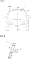
- FIG. 1 displays a schematic front view of a vehicle 100 including a vehicle body-use resin member 1 according to the present embodiment.
- the vehicle body-use resin member 1 according to the present embodiment is disposed on the upper portion of a window member 2 in the vehicle 100, and at least one in-vehicle member is mounted thereto.
- the vehicle body-use resin member 1 of the present embodiment is described in detail below.
- the vehicle body-use resin member according to the present embodiment is a resin member constituting a vehicle body (vehicle body-use resin member).
- the vehicle body is a concept distinguished from the window member.
- the window member is usually made of a laminated glass or a strengthened glass, and the passenger visually recognizes an exterior scene through the window member.
- the vehicle window member includes, for example, a window shield, a rear glass, and a side glass, etc.
- the vehicle body usually transmits substantially no visible light, and the passenger does not visually recognize an exterior scene through the vehicle body.
- the vehicle body-use resin member is sometimes simply referred to as "resin member”.
- the resin member of the present embodiment is a member to which an in-vehicle member is mounted.
- the resin member of the present embodiment is made of a resin and because of its high moldability or workability, can easily be formed into a shape suited for mounting an in-vehicle member.
- the shape suited for mounting an in-vehicle member includes, for example, a shape having a concave, a hole, a projection, and a planar portion, etc. for mounting an in-vehicle member.
- the method for forming the resin member of the present embodiment into such a shape is not particularly limited, but in view of cost, manhours and working accuracy, such a shape is preferably formed at the time of molding. That is, the resin member of the present embodiment is preferably a resin member formed by integral molding.
- the resin member of the present embodiment facilitates mounting of an in-vehicle member or since it is resin-made, hardly inhibits the function of the mounted in-vehicle member. Details are described later.
- the resin member of the present embodiment is a member suited for mounting an in-vehicle member. Also, the resin member of the present embodiment is mounted on the upper side of the window member in a vehicle and therefore, is suited particularly for mounting an in-vehicle member that is desired to be mounted at a high position.
- examples of the structure of the in-vehicle member of the present embodiment are specifically described by presenting examples of the in-vehicle member to be mounted.
- the in-vehicle member is a sensor
- the sensor mounted to a vehicle includes, for example, a camera such as visible light camera and infrared camera, a radar such as milli-wave radar, and LIDAR (Laser Imaging Detection and Ranging), etc.
- the sensor is desired to be mounted at a relatively high position in a vehicle so as to ensure a wide sensor range.
- the glass has a low transmittance of infrared light or milli-wave
- the infrared camera, LIDAR, or milli-wave radar cannot be mounted in the vehicle interior (on the inner side of a window member). Consequently, the sensor is usually mounted inside the front grill.
- the visible light camera can be mounted in the vehicle interior and is usually mounted on the inside upper portion of the window member.
- the visible light camera is mounted in this way, there is a problem that since the visible light camera detects visible light passed through the window member, the image obtained is an unclear and distorted image.
- a through hole is provided in part of the window member and the sensor is mounted so that an electromagnetic wave passed through the through hole can be detected.
- the window member is formed of a glass having low workability and moldability, enormous cost and manhours are required for providing such a through hole.
- the window member is usually in a curved-surface shape and is made of a glass having low workability and therefore, there is also a problem that mounting of the sensor to the window member is highly difficult and requires enormous cost and manhours.
- mounting since mounting is difficult, the sensor mounted suffers from poor stability and is readily subject to vibration during traveling of a vehicle, and this may adversely affect the function of the sensor.
- An example of the resin member of the present embodiment for solving the above-described conventional problems when mounting a sensor includes a resin member having a through hole.
- the sensor is mounted to the resin member so that an electromagnetic wave (visible light, infrared light, and milli-wave, etc.) passed through the through hole can be detected.
- an electromagnetic wave visible light, infrared light, and milli-wave, etc.
- the resin member of the present embodiment is made of a resin and has excellent moldability and workability and therefore, a through hole can be easily formed. Also, a sensor can be easily and stably mounted. Accordingly, when the resin member of the present embodiment is used, a sensor can be mounted at a high position easily without inhibiting the function.
- the size or shape of the through hole may be appropriately adjusted according to the size or shape of a sensor member to be mounted but usually, is a circle having a diameter of approximately from 1 to 3 cm.
- the method for fixing a sensor to the resin member includes, for example, a method of inserting a sensor into the through hole, a method of bonding a sensor to the resin member, a method of pressing a sensor against the resin member, and a method of fixing a sensor by use of a bracket or a sensor box, etc. Examples of the method for fixing a sensor to the resin member are described below by referring to FIG. 2 to FIG. 4 .
- the method of mounting a sensor to the resin member is not limited to these.
- FIG. 2 to FIG. 4 are enlarged views of, in the cross-sectional view along line A-A of FIG. 1 , the periphery of a region where an in-vehicle member is mounted in the resin member 1. This holds true for FIG. 5 to FIG. 8 .
- a sensor 3 is bonded to the resin member 1 and thereby fixed.
- the lens portion is preferably protected by a cover glass, etc.
- the transmittance of an electromagnetic wave that the sensor 3 detects is preferably high.
- the cover glass in the case of mounting a visible light camera, the cover glass is preferably formed of a glass having a high visible light transmittance.
- the cover glass in the case of mounting an infrared camera, the cover glass is preferably formed of a glass having a high infrared transmittance.
- the glass having a high infrared transmittance includes, for example, a chalcogenide glass.
- such a configuration when rain enters the inside of the through hole 4, the rain cannot be removed by a wiper. Accordingly, such a configuration preferably includes a mechanism, for example, for blowing air into the through hole so that the rain in the through hole 4 can be removed. Also, in order to prevent rain from entering the vehicle interior side from between the through hole and the sensor 3, the through hole 4 is preferably sealed by an optional member.
- the senor may be pressed against the resin member, for example, by a spring member and thereby fixed. In this case, from the viewpoint of sealing property, it is preferable to dispose a rubber member between the resin member and the sensor.
- FIG. 3 Another example illustrated in FIG. 3 is described.
- the sensor 3 is fixed to the resin member 1 via a bracket 6.
- a cover glass 5 is preferably provided at the vehicle exterior-side end of the through hole 4 as illustrated in FIG. 3 .
- integral molding of the bracket 6 and the resin member 1 is preferred as well.
- the senor 3 is housed in a sensor box 7, pressed against the resin member by a spring member 9, and fixed by being inserted into a through hole 4.
- the method for mounting the sensor box 7 to the resin member 1 is not particularly limited.
- the sensor box 7 may be bonded to the resin member 1. It is also possible to provide an engagement projection in the resin member 1 and insert the projection into an engagement concave provided in the sensor box 7.
- the shape of the engagement projection and concave is not particularly limited and may be appropriately adjusted to a shape facilitating the mounting.
- the sensor box 7 may be formed by integral molding with the resin member 1.
- the sensor 3 is fixed by being inserted into the through hole 4.
- the method for fixing the sensor 3 to the through hole 4 is not particularly limited.
- the method includes, for example, a method of fixing the sensor by an adhesive, a method of providing threads on the inner surface of the through hole 4 and the outer surface of the sensor 3 and screwing them together, and a method of providing, for example, a locking fixture, such as clip, on the sensor 3 and locking the sensor by the locking fixture.
- the sensor 3 may be fixed, for example, by being pressed against the resin member 1 from the inside of the sensor box 7 by a spring member 9.
- a rubber member 8 for filling a gap created between the sensor 3 and the resin member 1 is preferably disposed.
- a plurality of sensors may be housed in one sensor box.
- a hood, etc. covering the sensor top so as to prevent outside light from entering may be attached to the sensor.
- the method for mounting a sensor to the resin member is not limited to the above-described specific examples.
- the sensor in place of a sensor box, the sensor may be mounted by placing the sensor on a plate-like member composed of only the bottom plate of a sensor box and mounting the plate-like member to the resin member.
- the in-vehicle member is an antenna used for transmitting and receiving radio waves.
- An antenna is desired to be mounted at a relatively high position in a vehicle so as to facilitate transmission and reception of radio waves and is mounted, for example, on the inside upper portion of the window member.
- the glass hardly transmits radio waves in a high frequency band used for recent 4G or 5G, and this makes it difficult to dispose an antenna in the vehicle interior as in the past.
- the resin member of the present embodiment is made of a resin and, compared with the glass-made window member, it is easy to enhance the transparency to electromagnetic waves by adjusting the material or thickness, so that the resin member can also transmit radio waves in a high frequency band. Therefore, when the resin member of the present embodiment is used, an antenna can be mounted in the vehicle interior.
- the antenna can be mounted to the resin member 1, for example, by an adhesive, etc.
- the resin member 1 may have a concave 11 for mounting an antenna 10 as illustrated in FIG. 5 .
- the antenna 10 may be mounted by being inserted into a pocket 12 provided in the resin member 1 as illustrated in FIG. 6 .
- the antenna 10 is preferably fixed by being pressed against the inside of the pocket 12, for example, by a spring member 13, etc.
- the antenna 10 may be bonded, for example, to the inside of the pocket 12.
- a bracket is usually used for mounting an in-vehicle member, but the bracket is made of a metal and therefore, adversely affects transmission and reception of radio waves.
- the resin member of the present embodiment is made of a resin and because of its high moldability and workability, is easily formed into a shape suited for mounting various in-vehicle members. Therefore, the number of brackets used for mounting in-vehicle members can be reduced. Thus, from this viewpoint as well, the resin member of the present embodiment is suited for mounting an antenna.
- a room mirror is usually mounted to a window member through a mirror base bonded to the window member.
- the bonding surface of the mirror base is usually in a planar shape, and therefore, it is difficult to ensure the bonding strength as described above.
- the room mirror is recently required to be multi-functionalized and since the weight of the room mirror consequently increases, a mounting structure capable of more strongly mounting the room mirror is demanded.
- a first example of the resin member of the present embodiment for solving the above-described conventional problems is a resin member 1 having a planar portion 16 for mounting a mirror base 15 as illustrated in FIG. 7 . At this time, the surface may be roughened so as to enhance the adhesiveness. Also, a second example is a resin member 1 having an integrally molded mirror base 17 as illustrated in FIG. 8 .
- a mirror base 15 is mounted to the planar portion 16, and a room mirror 14 is mounted to the mirror base 15, whereby the room mirror 14 is firmly mounted.
- a room mirror 14 is mounted to the integrally molded mirror base 17, and the room mirror 14 is thereby firmly mounted.
- the method for mounting the mirror base 15 to the planar portion 16 in the first example is not particularly limited, but, for example, the mirror base can be mounted using an adhesive.
- in-vehicle members are recited, and examples of the resin member for mounting them are described, but the in-vehicle member mounted to the resin member of the present embodiment is not limited to those exemplified above.
- a plurality of in-vehicle members may be mounted to the in-vehicle member of the present embodiment.
- the shape of the resin member of the present embodiment is not particularly limited but may be, for example, a plate shape having a thickness of 2 to 30 mm.
- the thickness of the resin member may not be uniform and may be appropriately adjusted according to the strength required or the performance or mounting structure of a sensor, etc. to be mounted.
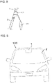
- the resin member 1 of the present embodiment may be provided, for example, throughout the width direction of the window member 2 as illustrated in FIG. 1 , or may be provided partially in the width direction of the window member 2 as illustrated in FIG. 9 .
- the resin member of the present embodiment may be painted or may not be painted when providing it in a vehicle.
- the resin member of the present embodiment is provided over a wide range as in the shape illustrated in FIG. 1 , for appearance reasons, the resin member is preferably painted with the same color as the vehicle body portion other than the resin member of the present embodiment.
- the resin member of the present embodiment is exposed directly to sunlight, outside air, rain, etc., and therefore, its weather resistance is preferably high.
- the weather resistance can be enhanced by coloring the resin member of the present embodiment black or incorporating a UV absorber or an antioxidant, etc. into the resin member of the present embodiment.
- the mounting structure of the in-vehicle member can be visually recognized from the outside of the vehicle, this is unfavorable in view of outer appearance. Therefore, in the case of not painting the resin member of the present embodiment, its visible light transmittance is preferably low. Specifically, the visible light transmittance is preferably 50% or less, more preferably 20% or less.
- the visible light transmittance above means the visible light transmittance determined in conformity with the Japanese Industrial Standards (JIS R3212-2015).
- the resin member of the present embodiment preferably has excellent heat resistance.
- the resin member of the present embodiment preferably has a deflection temperature under load of 50°C or more, more preferably 70°C or more, still more preferably 90°C or more.
- the deflection temperature under load above means the value measured in conformity with the Japanese Industrial Standards (JIS K7191-2-2007, 0.45 MPa).
- FIG. 10A to FIG. 10D depict enlarged views of, in the cross-sectional view along line A-A of FIG. 1 , the periphery of a joined portion of the resin member 1 and the window member 2.
- the resin member 1 and the window member 2 are joined, for example, by an adhesive.
- the structure of the joined portion may be a structure where as in FIG. 10A , end faces of the resin member 1 and the window member 2 are abutted against each other, or may be a structure where as in FIG. 10B , neighborhoods of both long sides of an end face of the resin member 1 are projected in a direction perpendicular to the end face and an end face of the window member 2 is fitted between the projecting portions.
- FIG. 10C or FIG. 10D the neighborhood of one long side of an end face of the resin member 1 may be projected in a direction perpendicular to the end face.
- structures of FIG. 10B to FIG. 10D are preferred, and particularly, in view of strength against impact from the outside of a vehicle, structures of FIG. 10B and FIG. 10C are preferred.
- junction of the resin member and the window member may be broken, or the window member or resin member may crack.
- this risk is pronounced.
- the coefficient of linear thermal expansion of the resin member of the present embodiment is preferably close to the coefficient of linear thermal expansion (about 9 ⁇ 10 -6 °C -1 ) of the window member.
- the coefficient of linear thermal expansion is preferably 80 ⁇ 10 -6 °C -1 or less, more preferably 60 ⁇ 10 -6 °C -1 or less, still more preferably 50 ⁇ 10 -6 °C -1 or less.
- the coefficient of linear thermal expansion above is a value measured based on Japanese Industrial Standards (JISK7140-1-2008).
- the material of the resin member of the present embodiment is not particularly limited.
- the resin serving as the material of the resin member of the present embodiment may be mixed with a filler for various purposes, for example, for enhancing the dimensional stability and heat resistance, enhancing the thermal function, e.g., imparting flame retardance, enhancing the mechanical properties such as strength or abrasion resistance, or enhancing the electric properties, magnetic properties and sound insulating properties.
- the shape of the filler is not limited and includes, for example, a spherical shape, a hollow shape, a granular shape, a plate-like shape, a bar shape, and a fiber shape, etc.
- the material of the filler is not limited as well and includes, for example, glass, an inorganic salt such as calcium carbonate, carbon, and aramid, etc.
- the material of the resin member of the present embodiment includes, for example, a fiber-reinforced plastic.
- the fiber-reinforced plastic includes, for example, carbon fiber-reinforced plastic (CFRP), CNF (cellulose nanofiber)-reinforced plastic, glass fiber-reinforced plastic (GFRP), and aramid fiber-reinforced plastic (AFRP), etc.
- a non-fiber-reinforced plastic can also be used.
- PVC polyvinyl chloride
- ABS resin ABS resin
- PMMA polyamide resin
- PA and nylon polyacetal
- POM polybutylene terephthalate
- PET polyethylene terephthalate
- PC polycarbonate
- PPS polyphenylene sulfide
- PEEK polyether ketone
- PES polyethersulfone
- PE polypropylene
- PE polyethylene
- Two or more kinds of these may be mixed to form a polymer alloy with the purpose of enhancing the performance.
- An additive may be added to the resin member of the present embodiment within a range not inhibiting the effects of the present invention, and, for example, a UV absorber or an antioxidant, etc. may be added.
- a processing such as coating may be applied to the resin member of the present embodiment within a range not inhibiting the effects of the present invention.
- the method for manufacturing the resin member of the present embodiment is not particularly limited but includes, for example, injection molding.
- the widow member with a vehicle body-use resin member of the present embodiment has a vehicle window member and the above-described resin member mounted to the upper portion of the vehicle window member.
- the composition of the window member is not particularly limited.
- the window member may be, for example, a window member composed of a laminated glass or a resin-made window member.
- the resin constituting the resin-made window member includes polycarbonate, a composite resin of cellulose nanofiber and polycarbonate, etc.
- the vehicle of the present embodiment is a vehicle having a window member and the above-described resin member at the upper portion of the window member.
- the vehicle of the present embodiment has a resin member at a relatively high position, and an in-vehicle member can be mounted to the resin member.
Landscapes
- Engineering & Computer Science (AREA)
- Mechanical Engineering (AREA)
- Radar, Positioning & Navigation (AREA)
- Remote Sensing (AREA)
- Physics & Mathematics (AREA)
- Computer Networks & Wireless Communication (AREA)
- General Physics & Mathematics (AREA)
- Multimedia (AREA)
- Electromagnetism (AREA)
- Compositions Of Macromolecular Compounds (AREA)
- Fittings On The Vehicle Exterior For Carrying Loads, And Devices For Holding Or Mounting Articles (AREA)
- Laminated Bodies (AREA)
Abstract
Description
- The present invention relates to a vehicle body-use resin member, a window member with a vehicle body-use resin member, and a vehicle.
- Various members such as various sensors, antenna and mirror (hereinafter, sometimes referred to as "in-vehicle members") are mounted to a vehicle. Due to, for example, advancement of a driving assistance technology, the number of types of in-vehicle members is increasing.
- For various reasons according to the types, some of in-vehicle members are desired to be disposed on the inner side of a window glass, i.e., in the vehicle interior. However, of these, some in-vehicle members are difficult to be disposed in the vehicle interior.
- For example, it is difficult to dispose an infrared camera in the vehicle interior, because the glass hardly transmits an infrared ray. In addition, the glass is also insufficiently transparent to radio waves at a frequency band of several GHz to several tens of GHz bands (hereinafter, sometimes referred to as "high frequency band") used in the recent communication in a fourth-generation mobile communication system (hereinafter, sometimes referred to as "4G") or a fifth-generation mobile communication system (hereinafter, sometimes referred to as "5G"). This makes it difficult to dispose an antenna in the vehicle interior as well.
- In consideration of these difficulties, various efforts are being made to dispose a variety of in-vehicle members in the vehicle interior.
- For example,
Patent Literature 1 discloses that part of the inner glass of a laminated glass used as a window glass is replaced by a radio wave transmitting material so as to make part of a window member be a region having a high radio wave transmittance. -
Patent Literature 2 discloses that a region partially lacking the inner glass is provided in a window member composed of a laminated glass to thereby enhance the transparency to electromagnetic waves. -
Patent Literature 3 discloses that part of a window glass is hollowed out and a material having a high infrared transmittance is inserted thereinto to partially provide a region having a high infrared transmittance in a window member. -
- Patent Literature 1: International Publication
WO 2017/188415 - Patent Literature 2:
JP-T-2011-502090 (the term "JP-T" as used herein means a published Japanese translation of a PCT - Patent Literature 3:
UK Unexamined Patent Publication No. 2271139 - However, in these literatures, difficulty of working of a window member or difficulty of mounting of an in-vehicle member is not sufficiently discussed.
- All of window members described in
Patent Literatures 1 to 3 must be shaped to let part of a glass be cut out or hollowed out. However, the glass has low moldability and workability, and therefore, the working above requires enormous cost and manhours or the periphery of the worked portion is distorted, presenting a problem with the outer appearance or the performance of an in-vehicle member mounted. - Also, the method for mounting an in-vehicle member to a window member includes, for example, a method of providing a concave or a hole in a window member and mounting an in-vehicle member in the concave or hole. However, due to low moldability and workability of the glass, such working requires enormous cost and manhours as well. In addition, compared with the positioning accuracy required for mounting of an in-vehicle member, the working accuracy is sometimes insufficient.
- Other methods for mounting an in-vehicle member to a window member include a method of bonding a bracket to a window member and mounting an in-vehicle member via the bracket. However, while the window member is in a curved-surface shape, the bonding surface of the bracket is fundamentally in a planar shape, and therefore, it is difficult to ensure the bonding area and in turn, the bonding strength. Accordingly, application of such a method is difficult when the in-vehicle member is heavy. Although it may be considered to use an adhesive having thickness and flexibility and capable of relieving the difference in the bonding surface shape such as urethane, etc., such a method causes an increase in the cost or manhours and moreover, the bonded in-vehicle member is susceptible to vibration, which may adversely affect the function of the in-vehicle member.
- In addition, other methods for mounting an in-vehicle member to a window member include, for example, a method of bonding an in-vehicle member to a window member, but this method also involves the same problem as in the case of bonding a bracket.
- Furthermore, in the window member described in
Patent Literature - The present invention has been accomplished in consideration of these circumstances, and an object thereof is to provide a vehicle body-use resin member suited for mounting an in-vehicle member. Another object is to provide a vehicle body-use resin member-equipped widow member including the vehicle body-use resin member, and a vehicle.
- The vehicle body-use resin member of one embodiment according to the present invention for solving the problems above is a vehicle body-use resin member disposed on an upper portion of a window member in a vehicle, wherein at least one in-vehicle member is mounted.
- In one embodiment of the vehicle body-use resin member of the present invention, at least one of the in-vehicle members is a sensor, and the vehicle body-use resin member may have a through hole.
- In one embodiment of the vehicle body-use resin member of the present invention, at least one of the in-vehicle members is an antenna, and the vehicle body-use resin member may have a concave for mounting the antenna.
- In one embodiment of the vehicle body-use resin member of the present invention, at least one of the in-vehicle members is a mirror, and the vehicle body-use resin member may have a planar portion for mounting a mirror base of the mirror.
- In one embodiment of the vehicle body-use resin member of the present invention, at least one of the in-vehicle members is a mirror, and a mirror base of the mirror may be integrally molded with the vehicle body-use resin member.
- In one embodiment of the vehicle body-use resin member of the present invention, the visible light transmittance may be 50% or less.
- In one embodiment of the vehicle body-use resin member of the present invention, the deflection temperature under load may be 50°C or more.
- In one embodiment of the vehicle body-use resin member of the present invention, the coefficient of linear thermal expansion may be 80×10-6°C-1 or less.
- Also, the vehicle body-use resin member-equipped window member of one embodiment according to the present invention includes a window member and the vehicle body-use resin member of the present invention disposed on the upper portion of the window member.
- In one embodiment of the vehicle body-use resin member-equipped window member of the present invention, at least one in-vehicle member mounted to the vehicle body-use resin member may further be provided.
- In addition, the vehicle of one embodiment according to the present invention includes a window member and the vehicle body-use resin member of the present invention disposed on the upper portion of the window member.
- In one embodiment of the vehicle of the present invention, at least one in-vehicle member mounted to the vehicle body-use resin member may further be provided.
- The vehicle body-use resin member according to one embodiment of the present invention is suited for mounting an in-vehicle member. Also, each of the vehicle body-use resin member-equipped widow member and the vehicle includes a vehicle body-use resin member suited for mounting an in-vehicle member.
-
- [
FIG. 1] FIG. 1 is a schematic front view of a vehicle including the vehicle body-use resin member according to one embodiment of the present invention. - [
FIG. 2] FIG. 2 is one example of the enlarged view of, in the cross-sectional view along line A-A ofFIG. 1 , the periphery of a region where an in-vehicle member is mounted in the vehicle body-use resin member. - [
FIG. 3] FIG. 3 is another example of the enlarged view of the periphery of, in the cross-sectional view along line A-A ofFIG. 1 , a region where an in-vehicle member is mounted in the vehicle body-use resin member. - [
FIG. 4] FIG. 4 is another example of the enlarged view of the periphery of, in the cross-sectional view along line A-A ofFIG. 1 , a region where an in-vehicle member is mounted in the vehicle body-use resin member. - [
FIG. 5] FIG. 5 is another example of the enlarged view of the periphery of, in the cross-sectional view along line A-A ofFIG. 1 , a region where an in-vehicle member is mounted in the vehicle body-use resin member. - [
FIG. 6] FIG. 6 is another example of the enlarged view of the periphery of, in the cross-sectional view along line A-A ofFIG. 1 , a region where an in-vehicle member is mounted in the vehicle body-use resin member. - [
FIG. 7] FIG. 7 is another example of the enlarged view of the periphery of, in the cross-sectional view along line A-A ofFIG. 1 , a region where an in-vehicle member is mounted in the vehicle body-use resin member. - [
FIG. 8] FIG. 8 is another example of the enlarged view of the periphery of, in the cross-sectional view along line A-A ofFIG. 1 , a region where an in-vehicle member is mounted in the vehicle body-use resin member. - [
FIG. 9] FIG. 9 is a schematic front view of a vehicle including the vehicle body-use resin member according to another embodiment of the present invention. - [
FIG. 10A] FIG. 10A is one example of the enlarged view of, in the cross-sectional view along line A-A ofFIG. 1 , the periphery of a joined portion of the vehicle body-use resin member and the window member. - [
FIG. 10B] FIG. 10B is another example of the enlarged view of, in the cross-sectional view along line A-A ofFIG. 1 , the periphery of a joined portion of the vehicle body-use resin member and the window member. - [
FIG. 10C] FIG. 10C is another example of the enlarged view of, in the cross-sectional view along line A-A ofFIG. 1 , the periphery of a joined portion of the vehicle body-use resin member and the window member. - [
FIG. 10D] FIG. 10D is another example of the enlarged view of, in the cross-sectional view along line A-A ofFIG. 1 , the periphery of a joined portion of the vehicle body-use resin member and the window member. - Embodiments of the present invention are described below. The present invention is not limited to the embodiments described below. Also, in the drawings, embodiments are schematically depicted to clearly describe the present invention and not to accurately represent the actual size or scale.
-
FIG. 1 displays a schematic front view of avehicle 100 including a vehicle body-use resin member 1 according to the present embodiment. The vehicle body-use resin member 1 according to the present embodiment is disposed on the upper portion of awindow member 2 in thevehicle 100, and at least one in-vehicle member is mounted thereto. The vehicle body-use resin member 1 of the present embodiment is described in detail below. - The vehicle body-use resin member according to the present embodiment is a resin member constituting a vehicle body (vehicle body-use resin member).
- In the present description, the vehicle body is a concept distinguished from the window member. The window member is usually made of a laminated glass or a strengthened glass, and the passenger visually recognizes an exterior scene through the window member. The vehicle window member includes, for example, a window shield, a rear glass, and a side glass, etc. On the other hand, the vehicle body usually transmits substantially no visible light, and the passenger does not visually recognize an exterior scene through the vehicle body.
- In the following, the vehicle body-use resin member is sometimes simply referred to as "resin member".
- The resin member of the present embodiment is a member to which an in-vehicle member is mounted. The resin member of the present embodiment is made of a resin and because of its high moldability or workability, can easily be formed into a shape suited for mounting an in-vehicle member. The shape suited for mounting an in-vehicle member includes, for example, a shape having a concave, a hole, a projection, and a planar portion, etc. for mounting an in-vehicle member. The method for forming the resin member of the present embodiment into such a shape is not particularly limited, but in view of cost, manhours and working accuracy, such a shape is preferably formed at the time of molding. That is, the resin member of the present embodiment is preferably a resin member formed by integral molding.
- The resin member of the present embodiment facilitates mounting of an in-vehicle member or since it is resin-made, hardly inhibits the function of the mounted in-vehicle member. Details are described later.
- Due to these characteristic features, the resin member of the present embodiment is a member suited for mounting an in-vehicle member. Also, the resin member of the present embodiment is mounted on the upper side of the window member in a vehicle and therefore, is suited particularly for mounting an in-vehicle member that is desired to be mounted at a high position. In the following, examples of the structure of the in-vehicle member of the present embodiment are specifically described by presenting examples of the in-vehicle member to be mounted.
- First, a case where the in-vehicle member is a sensor is described. Here, the sensor mounted to a vehicle includes, for example, a camera such as visible light camera and infrared camera, a radar such as milli-wave radar, and LIDAR (Laser Imaging Detection and Ranging), etc.
- The sensor is desired to be mounted at a relatively high position in a vehicle so as to ensure a wide sensor range. However, since the glass has a low transmittance of infrared light or milli-wave, the infrared camera, LIDAR, or milli-wave radar cannot be mounted in the vehicle interior (on the inner side of a window member). Consequently, the sensor is usually mounted inside the front grill.
- On the other hand, visible light passes through the glass and therefore, the visible light camera can be mounted in the vehicle interior and is usually mounted on the inside upper portion of the window member. However, in the case where the visible light camera is mounted in this way, there is a problem that since the visible light camera detects visible light passed through the window member, the image obtained is an unclear and distorted image.
- In order to solve the problem above, there may be considered a method where a through hole is provided in part of the window member and the sensor is mounted so that an electromagnetic wave passed through the through hole can be detected. However, since the window member is formed of a glass having low workability and moldability, enormous cost and manhours are required for providing such a through hole.
- Furthermore, the window member is usually in a curved-surface shape and is made of a glass having low workability and therefore, there is also a problem that mounting of the sensor to the window member is highly difficult and requires enormous cost and manhours. In addition, since mounting is difficult, the sensor mounted suffers from poor stability and is readily subject to vibration during traveling of a vehicle, and this may adversely affect the function of the sensor.
- An example of the resin member of the present embodiment for solving the above-described conventional problems when mounting a sensor includes a resin member having a through hole. The sensor is mounted to the resin member so that an electromagnetic wave (visible light, infrared light, and milli-wave, etc.) passed through the through hole can be detected.
- The resin member of the present embodiment is made of a resin and has excellent moldability and workability and therefore, a through hole can be easily formed. Also, a sensor can be easily and stably mounted. Accordingly, when the resin member of the present embodiment is used, a sensor can be mounted at a high position easily without inhibiting the function.
- The size or shape of the through hole may be appropriately adjusted according to the size or shape of a sensor member to be mounted but usually, is a circle having a diameter of approximately from 1 to 3 cm.
- The method for fixing a sensor to the resin member includes, for example, a method of inserting a sensor into the through hole, a method of bonding a sensor to the resin member, a method of pressing a sensor against the resin member, and a method of fixing a sensor by use of a bracket or a sensor box, etc. Examples of the method for fixing a sensor to the resin member are described below by referring to
FIG. 2 to FIG. 4 . The method of mounting a sensor to the resin member is not limited to these.FIG. 2 to FIG. 4 are enlarged views of, in the cross-sectional view along line A-A ofFIG. 1 , the periphery of a region where an in-vehicle member is mounted in theresin member 1. This holds true forFIG. 5 to FIG. 8 . - In the example illustrated in
FIG. 2 , asensor 3 is bonded to theresin member 1 and thereby fixed. When a lens portion of thesensor 3 is exposed to the vehicle exterior as in the example illustrated inFIG. 2 , the lens portion is preferably protected by a cover glass, etc. - In the cover glass, the transmittance of an electromagnetic wave that the
sensor 3 detects is preferably high. For example, in the case of mounting a visible light camera, the cover glass is preferably formed of a glass having a high visible light transmittance. Also, in the case of mounting an infrared camera, the cover glass is preferably formed of a glass having a high infrared transmittance. The glass having a high infrared transmittance includes, for example, a chalcogenide glass. - In such a configuration, when rain enters the inside of the through
hole 4, the rain cannot be removed by a wiper. Accordingly, such a configuration preferably includes a mechanism, for example, for blowing air into the through hole so that the rain in the throughhole 4 can be removed. Also, in order to prevent rain from entering the vehicle interior side from between the through hole and thesensor 3, the throughhole 4 is preferably sealed by an optional member. - Instead of an adhesive, the sensor may be pressed against the resin member, for example, by a spring member and thereby fixed. In this case, from the viewpoint of sealing property, it is preferable to dispose a rubber member between the resin member and the sensor.
- Next, another example illustrated in
FIG. 3 is described. In the example illustrated inFIG. 3 , thesensor 3 is fixed to theresin member 1 via abracket 6. In this example, acover glass 5 is preferably provided at the vehicle exterior-side end of the throughhole 4 as illustrated inFIG. 3 . In order to enhance the mounting stability of thesensor 3, it is also preferable to provide a planar portion in theresin member 1 and mount thebracket 6 thereto. In addition, integral molding of thebracket 6 and theresin member 1 is preferred as well. - Next, another example illustrated in
FIG. 4 is described. In the example illustrated inFIG. 4 , thesensor 3 is housed in asensor box 7, pressed against the resin member by a spring member 9, and fixed by being inserted into a throughhole 4. - The method for mounting the
sensor box 7 to theresin member 1 is not particularly limited. For example, thesensor box 7 may be bonded to theresin member 1. It is also possible to provide an engagement projection in theresin member 1 and insert the projection into an engagement concave provided in thesensor box 7. The shape of the engagement projection and concave is not particularly limited and may be appropriately adjusted to a shape facilitating the mounting. In addition, thesensor box 7 may be formed by integral molding with theresin member 1. - In this example, the
sensor 3 is fixed by being inserted into the throughhole 4. The method for fixing thesensor 3 to the throughhole 4 is not particularly limited. The method includes, for example, a method of fixing the sensor by an adhesive, a method of providing threads on the inner surface of the throughhole 4 and the outer surface of thesensor 3 and screwing them together, and a method of providing, for example, a locking fixture, such as clip, on thesensor 3 and locking the sensor by the locking fixture. - The
sensor 3 may be fixed, for example, by being pressed against theresin member 1 from the inside of thesensor box 7 by a spring member 9. In this case, arubber member 8 for filling a gap created between thesensor 3 and theresin member 1 is preferably disposed. - In the case of mounting a plurality of sensors, a plurality of sensors may be housed in one sensor box. In addition, a hood, etc. covering the sensor top so as to prevent outside light from entering may be attached to the sensor.
- The method for mounting a sensor to the resin member is not limited to the above-described specific examples. For example, in place of a sensor box, the sensor may be mounted by placing the sensor on a plate-like member composed of only the bottom plate of a sensor box and mounting the plate-like member to the resin member.
- Next, the case where the in-vehicle member is an antenna used for transmitting and receiving radio waves is described.
- An antenna is desired to be mounted at a relatively high position in a vehicle so as to facilitate transmission and reception of radio waves and is mounted, for example, on the inside upper portion of the window member. However, the glass hardly transmits radio waves in a high frequency band used for recent 4G or 5G, and this makes it difficult to dispose an antenna in the vehicle interior as in the past.
- On the other hand, the resin member of the present embodiment is made of a resin and, compared with the glass-made window member, it is easy to enhance the transparency to electromagnetic waves by adjusting the material or thickness, so that the resin member can also transmit radio waves in a high frequency band. Therefore, when the resin member of the present embodiment is used, an antenna can be mounted in the vehicle interior.
- The antenna can be mounted to the
resin member 1, for example, by an adhesive, etc. In the case where an antenna is mounted, theresin member 1 may have a concave 11 for mounting anantenna 10 as illustrated inFIG. 5 . - For example, the
antenna 10 may be mounted by being inserted into apocket 12 provided in theresin member 1 as illustrated inFIG. 6 . In order to suppress the vibration of theantenna 10 in thepocket 12, theantenna 10 is preferably fixed by being pressed against the inside of thepocket 12, for example, by aspring member 13, etc. Theantenna 10 may be bonded, for example, to the inside of thepocket 12. - Furthermore, a bracket is usually used for mounting an in-vehicle member, but the bracket is made of a metal and therefore, adversely affects transmission and reception of radio waves. On the other hand, the resin member of the present embodiment is made of a resin and because of its high moldability and workability, is easily formed into a shape suited for mounting various in-vehicle members. Therefore, the number of brackets used for mounting in-vehicle members can be reduced. Thus, from this viewpoint as well, the resin member of the present embodiment is suited for mounting an antenna.
- Next, the case where the in-vehicle member is a room mirror is described.
- A room mirror is usually mounted to a window member through a mirror base bonded to the window member. However, while the window member is in a curved-surface shape, the bonding surface of the mirror base is usually in a planar shape, and therefore, it is difficult to ensure the bonding strength as described above. Nevertheless, the room mirror is recently required to be multi-functionalized and since the weight of the room mirror consequently increases, a mounting structure capable of more strongly mounting the room mirror is demanded.
- In the case where a
room mirror 14 is mounted, a first example of the resin member of the present embodiment for solving the above-described conventional problems is aresin member 1 having aplanar portion 16 for mounting amirror base 15 as illustrated inFIG. 7 . At this time, the surface may be roughened so as to enhance the adhesiveness. Also, a second example is aresin member 1 having an integrally moldedmirror base 17 as illustrated inFIG. 8 . - In the
resin member 1 of the first example, amirror base 15 is mounted to theplanar portion 16, and aroom mirror 14 is mounted to themirror base 15, whereby theroom mirror 14 is firmly mounted. Also, in theresin member 1 of the second example, aroom mirror 14 is mounted to the integrally moldedmirror base 17, and theroom mirror 14 is thereby firmly mounted. The method for mounting themirror base 15 to theplanar portion 16 in the first example is not particularly limited, but, for example, the mirror base can be mounted using an adhesive. - In the foregoing pages, representative in-vehicle members are recited, and examples of the resin member for mounting them are described, but the in-vehicle member mounted to the resin member of the present embodiment is not limited to those exemplified above. In addition, a plurality of in-vehicle members may be mounted to the in-vehicle member of the present embodiment.
- The shape of the resin member of the present embodiment is not particularly limited but may be, for example, a plate shape having a thickness of 2 to 30 mm. The thickness of the resin member may not be uniform and may be appropriately adjusted according to the strength required or the performance or mounting structure of a sensor, etc. to be mounted. The
resin member 1 of the present embodiment may be provided, for example, throughout the width direction of thewindow member 2 as illustrated inFIG. 1 , or may be provided partially in the width direction of thewindow member 2 as illustrated inFIG. 9 . - The resin member of the present embodiment may be painted or may not be painted when providing it in a vehicle. In the case where the resin member of the present embodiment is provided over a wide range as in the shape illustrated in
FIG. 1 , for appearance reasons, the resin member is preferably painted with the same color as the vehicle body portion other than the resin member of the present embodiment. - On the other hand, in the case of being not painted, the resin member of the present embodiment is exposed directly to sunlight, outside air, rain, etc., and therefore, its weather resistance is preferably high. The weather resistance can be enhanced by coloring the resin member of the present embodiment black or incorporating a UV absorber or an antioxidant, etc. into the resin member of the present embodiment.
- If the mounting structure of the in-vehicle member can be visually recognized from the outside of the vehicle, this is unfavorable in view of outer appearance. Therefore, in the case of not painting the resin member of the present embodiment, its visible light transmittance is preferably low. Specifically, the visible light transmittance is preferably 50% or less, more preferably 20% or less. Here, the visible light transmittance above means the visible light transmittance determined in conformity with the Japanese Industrial Standards (JIS R3212-2015).
- Since the region where the resin member of the present embodiment is mounted is a region that is relatively likely to rise in the temperature due to sunlight, etc., the resin member of the present embodiment preferably has excellent heat resistance. Specifically, the resin member of the present embodiment preferably has a deflection temperature under load of 50°C or more, more preferably 70°C or more, still more preferably 90°C or more. The deflection temperature under load above means the value measured in conformity with the Japanese Industrial Standards (JIS K7191-2-2007, 0.45 MPa).
- For explaining the joined portion of the resin member and the window member,
FIG. 10A to FIG. 10D depict enlarged views of, in the cross-sectional view along line A-A ofFIG. 1 , the periphery of a joined portion of theresin member 1 and thewindow member 2. - The
resin member 1 and thewindow member 2 are joined, for example, by an adhesive. The structure of the joined portion may be a structure where as inFIG. 10A , end faces of theresin member 1 and thewindow member 2 are abutted against each other, or may be a structure where as inFIG. 10B , neighborhoods of both long sides of an end face of theresin member 1 are projected in a direction perpendicular to the end face and an end face of thewindow member 2 is fitted between the projecting portions. Also, as inFIG. 10C orFIG. 10D , the neighborhood of one long side of an end face of theresin member 1 may be projected in a direction perpendicular to the end face. In view of strength, structures ofFIG. 10B to FIG. 10D are preferred, and particularly, in view of strength against impact from the outside of a vehicle, structures ofFIG. 10B and FIG. 10C are preferred. - If the difference in the thermal expansion coefficient between the resin member and the window member is large, junction of the resin member and the window member may be broken, or the window member or resin member may crack. Among others, when the resin member is provided throughout the width direction of the window member as illustrated in
FIG. 1 , this risk is pronounced. - For this reason, the coefficient of linear thermal expansion of the resin member of the present embodiment is preferably close to the coefficient of linear thermal expansion (about 9×10⁻⁶°C-1) of the window member. Specifically, the coefficient of linear thermal expansion is preferably 80×10-6°C-1 or less, more preferably 60×10-6°C-1 or less, still more preferably 50×10-6°C-1 or less. The coefficient of linear thermal expansion above is a value measured based on Japanese Industrial Standards (JISK7140-1-2008).
- The material of the resin member of the present embodiment is not particularly limited. Also, the resin serving as the material of the resin member of the present embodiment may be mixed with a filler for various purposes, for example, for enhancing the dimensional stability and heat resistance, enhancing the thermal function, e.g., imparting flame retardance, enhancing the mechanical properties such as strength or abrasion resistance, or enhancing the electric properties, magnetic properties and sound insulating properties. The shape of the filler is not limited and includes, for example, a spherical shape, a hollow shape, a granular shape, a plate-like shape, a bar shape, and a fiber shape, etc. The material of the filler is not limited as well and includes, for example, glass, an inorganic salt such as calcium carbonate, carbon, and aramid, etc.
- The material of the resin member of the present embodiment includes, for example, a fiber-reinforced plastic. The fiber-reinforced plastic includes, for example, carbon fiber-reinforced plastic (CFRP), CNF (cellulose nanofiber)-reinforced plastic, glass fiber-reinforced plastic (GFRP), and aramid fiber-reinforced plastic (AFRP), etc.
- As the material of the resin member of the present embodiment, a non-fiber-reinforced plastic can also be used. For example, polyvinyl chloride (PVC), ABS resin, acryl (PMMA), polyamide resin (including PA and nylon), polyacetal (POM), polybutylene terephthalate (PBT), polyethylene terephthalate (PET), polycarbonate (PC), polyphenylene sulfide (PPS), polyether ketone (PEEK), polyethersulfone (PES), polypropylene (PP), and polyethylene (PE), etc. can be used.
- Two or more kinds of these may be mixed to form a polymer alloy with the purpose of enhancing the performance.
- An additive may be added to the resin member of the present embodiment within a range not inhibiting the effects of the present invention, and, for example, a UV absorber or an antioxidant, etc. may be added. A processing such as coating may be applied to the resin member of the present embodiment within a range not inhibiting the effects of the present invention.
- The method for manufacturing the resin member of the present embodiment is not particularly limited but includes, for example, injection molding.
- Next, the widow member with a vehicle body-use resin member of the present embodiment is described. The widow member with a vehicle body-use resin member of the present embodiment has a vehicle window member and the above-described resin member mounted to the upper portion of the vehicle window member.
- In the widow member with a vehicle body-use resin member of the present embodiment, the composition of the window member is not particularly limited. The window member may be, for example, a window member composed of a laminated glass or a resin-made window member. The resin constituting the resin-made window member includes polycarbonate, a composite resin of cellulose nanofiber and polycarbonate, etc.
- Next, the vehicle of the present embodiment is described. The vehicle of the present embodiment is a vehicle having a window member and the above-described resin member at the upper portion of the window member. The vehicle of the present embodiment has a resin member at a relatively high position, and an in-vehicle member can be mounted to the resin member.
- Various embodiments have been described hereinabove while referring to the drawings, but, of course, the present invention is not limited to these examples. It is apparent to one skilled in the art that various modification examples or correction examples can be conceived within the scope set forth in the claims, and it should be understood that these modification or correction examples also naturally belong to the technical scope of the present invention. Also, respective constituent elements in the embodiments above may be combined within a range not departing from the gist of the present invention.
- This application is based on
Japanese Patent Application (Patent Application No. 2019-126898) filed on July 8, 2019 -
- 1:
- Vehicle body-use resin member
- 2:
- Window member
- 3:
- Sensor
- 4:
- Through hole
- 5:
- Cover glass
- 6:
- Bracket
- 7:
- Sensor box
- 8:
- Rubber member
- 9:
- Spring member
- 10:
- Antenna
- 11:
- Concave
- 12:
- 13:
- Spring member
- 14:
- Room mirror
- 15:
- Mirror base
- 16:
- Planar portion
- 17:
- Mirror base
- 100:
- Vehicle
Claims (12)
- A vehicle body-use resin member disposed on an upper portion of a window member in a vehicle, wherein at least one in-vehicle member is mounted on the vehicle body-use resin member.
- The vehicle body-use resin member according to claim 1, wherein at least one of the in-vehicle members is a sensor, and the vehicle body-use resin member comprises a through hole.
- The vehicle body-use resin member according to claim 1 or 2, wherein at least one of the in-vehicle members is an antenna, and the vehicle body-use resin member comprises a concave for mounting the antenna.
- The vehicle body-use resin member according to any one of claims 1 to 3, wherein at least one of the in-vehicle members is a mirror, and the vehicle body-use resin member comprises a planar portion for mounting a mirror base of the mirror.
- The vehicle body-use resin member according to any one of claims 1 to 3, wherein at least one of the in-vehicle members is a mirror, and a mirror base of the mirror is integrally molded with the vehicle body-use resin member.
- The vehicle body-use resin member according to any one of claims 1 to 5, having a visible light transmittance of 50% or less.
- The vehicle body-use resin member according to any one of claims 1 to 6, having a deflection temperature under load of 50°C or more.
- The vehicle body-use resin member according to any one of claims 1 to 7, having a coefficient of linear thermal expansion of 80×10-6°C-1 or less.
- The vehicle body-use resin member-equipped window member comprising a window member and the vehicle body-use resin member according to any one of claims 1 to 8 disposed on the upper portion of the window member.
- A vehicle body-use resin member-equipped window member according to claim 9, wherein at least one in-vehicle member mounted to the vehicle body-use resin member is further provided.
- A vehicle comprising a window member and the vehicle body-use resin member according to any one of claims 1 to 8 disposed on the upper portion of the window member.
- The vehicle according to claim 11, wherein at least one in-vehicle member mounted to the vehicle body-use resin member is further provided.
Applications Claiming Priority (2)
| Application Number | Priority Date | Filing Date | Title |
|---|---|---|---|
| JP2019126898 | 2019-07-08 | ||
| PCT/JP2020/024069 WO2021006004A1 (en) | 2019-07-08 | 2020-06-19 | Vehicle body resin member, window member with vehicle body resin member, and vehicle |
Publications (2)
| Publication Number | Publication Date |
|---|---|
| EP3998177A1 true EP3998177A1 (en) | 2022-05-18 |
| EP3998177A4 EP3998177A4 (en) | 2023-08-02 |
Family
ID=74114849
Family Applications (1)
| Application Number | Title | Priority Date | Filing Date |
|---|---|---|---|
| EP20836624.5A Pending EP3998177A4 (en) | 2019-07-08 | 2020-06-19 | VEHICLE BODY RESIN ELEMENT, WINDOW ELEMENT PROVIDED WITH VEHICLE BODY RESIN ELEMENT AND VEHICLE |
Country Status (5)
| Country | Link |
|---|---|
| US (1) | US12065025B2 (en) |
| EP (1) | EP3998177A4 (en) |
| JP (1) | JP7424378B2 (en) |
| CN (1) | CN114072315A (en) |
| WO (1) | WO2021006004A1 (en) |
Cited By (1)
| Publication number | Priority date | Publication date | Assignee | Title |
|---|---|---|---|---|
| WO2025202489A1 (en) * | 2024-03-29 | 2025-10-02 | Saint-Gobain Sekurit France | Assembly comprising a vehicle glazing unit provided with a through-hole for using an infrared camera |
Families Citing this family (6)
| Publication number | Priority date | Publication date | Assignee | Title |
|---|---|---|---|---|
| DE102019128013A1 (en) * | 2019-10-17 | 2021-04-22 | Bayerische Motoren Werke Aktiengesellschaft | Vehicle component for integrating an environment detection sensor into a vehicle |
| EP4071926A4 (en) * | 2019-12-03 | 2023-12-27 | Kuraray Co., Ltd. | Antenna system and antenna circuit board |
| JP2021116352A (en) * | 2020-01-27 | 2021-08-10 | ポリプラスチックス株式会社 | Onboard optical module component |
| FR3127633B1 (en) * | 2021-09-24 | 2025-05-30 | Lynred | Infrared imaging device |
| WO2023119316A1 (en) * | 2021-12-21 | 2023-06-29 | Saint-Gobain Glass France | An automotive glazing with integrated radar unit |
| CN114734929A (en) * | 2022-04-27 | 2022-07-12 | 福耀玻璃工业集团股份有限公司 | Vehicle window glass assembly and control method thereof |
Family Cites Families (30)
| Publication number | Priority date | Publication date | Assignee | Title |
|---|---|---|---|---|
| JPH0633433Y2 (en) * | 1988-04-15 | 1994-08-31 | 日産自動車株式会社 | Vehicle monitoring device |
| EP0609453B1 (en) | 1992-06-25 | 2002-10-23 | Denso Corporation | Mobile object identification device |
| JPH06180775A (en) * | 1992-12-14 | 1994-06-28 | Nippondenso Co Ltd | Electronic mark for vehicle |
| GB2271139A (en) | 1992-10-03 | 1994-04-06 | Pilkington Plc | Vehicle window with insert of high infra-red transmittance |
| JPH07215131A (en) * | 1994-01-31 | 1995-08-15 | Asahi Glass Co Ltd | Mirror base mounting structure and mounting method on glass plate surface |
| US6326613B1 (en) * | 1998-01-07 | 2001-12-04 | Donnelly Corporation | Vehicle interior mirror assembly adapted for containing a rain sensor |
| JP2002337612A (en) * | 2001-05-15 | 2002-11-27 | Murakami Corp | Room mirror with built-in antenna |
| JP2003146134A (en) * | 2001-11-14 | 2003-05-21 | Ichikoh Ind Ltd | Inner mirror device |
| US20070216768A1 (en) * | 2006-03-14 | 2007-09-20 | Ford Global Technologies, Llc | Device and method for outwardly looking ir camera mounted inside vehicles particularly suited for pre-crash sensing and pedestrian detection |
| JP2007269205A (en) * | 2006-03-31 | 2007-10-18 | Yupiteru Ind Co Ltd | On-vehicle device fixing device |
| DE102007042028A1 (en) | 2007-09-05 | 2009-03-12 | Saint-Gobain Sekurit Deutschland Gmbh & Co. Kg | Disk with a detector for electromagnetic radiation |
| JP2009234432A (en) * | 2008-03-27 | 2009-10-15 | Nissan Motor Co Ltd | Window material for automobile |
| JP2010234867A (en) * | 2009-03-30 | 2010-10-21 | Daikyonishikawa Corp | Vehicle wind panel |
| JP2012206721A (en) * | 2012-07-17 | 2012-10-25 | Mitsubishi Engineering Plastics Corp | Panel structure having window |
| WO2014107498A1 (en) * | 2013-01-02 | 2014-07-10 | Sabic Innovative Plastics Ip B.V. | Polymers, articles comprising polymers, and methods of making and using the same |
| JP2015107764A (en) * | 2013-12-05 | 2015-06-11 | 株式会社豊田自動織機 | Camera mounting structure |
| US10336163B2 (en) * | 2014-03-14 | 2019-07-02 | Nippon Sheet Glass Company, Limited | Windshield |
| JP6480249B2 (en) * | 2014-11-04 | 2019-03-06 | 日本板硝子株式会社 | Windshield |
| WO2016143582A1 (en) * | 2015-03-12 | 2016-09-15 | 日本板硝子株式会社 | Windshield |
| JP2016175447A (en) * | 2015-03-18 | 2016-10-06 | トヨタ自動車株式会社 | vehicle |
| WO2017188415A1 (en) | 2016-04-27 | 2017-11-02 | 旭硝子株式会社 | Window member and vehicle window glass |
| JP6904337B2 (en) | 2016-04-27 | 2021-07-14 | Agc株式会社 | Laminating plate with bracket |
| WO2017188414A1 (en) | 2016-04-27 | 2017-11-02 | 旭硝子株式会社 | Resin body, and glass plate article |
| US9963018B2 (en) * | 2016-06-27 | 2018-05-08 | Toyota Motor Engineering & Manufacturing North America, Inc. | Vehicles and vehicle roof structures for concealing one or more sensors |
| CN109641793B (en) * | 2016-07-29 | 2022-02-01 | 日本板硝子株式会社 | Windshield and method for manufacturing windshield |
| DE112018001377T5 (en) * | 2017-03-15 | 2019-11-28 | AGC Inc. | Laminated glass for a vehicle with an interior mirror |
| JP6896533B2 (en) * | 2017-07-04 | 2021-06-30 | 富士フイルム株式会社 | Head-up display |
| WO2019049606A1 (en) * | 2017-09-06 | 2019-03-14 | 富士フイルム株式会社 | Imaging device |
| JP6950547B2 (en) | 2018-01-26 | 2021-10-13 | 工機ホールディングス株式会社 | Strike work machine |
| JP2019166964A (en) * | 2018-03-23 | 2019-10-03 | ソニーセミコンダクタソリューションズ株式会社 | Imaging system and vehicle window for use therein |
-
2020
- 2020-06-19 EP EP20836624.5A patent/EP3998177A4/en active Pending
- 2020-06-19 WO PCT/JP2020/024069 patent/WO2021006004A1/en not_active Ceased
- 2020-06-19 JP JP2021530566A patent/JP7424378B2/en active Active
- 2020-06-19 CN CN202080049282.8A patent/CN114072315A/en active Pending
-
2022
- 2022-01-03 US US17/646,726 patent/US12065025B2/en active Active
Cited By (2)
| Publication number | Priority date | Publication date | Assignee | Title |
|---|---|---|---|---|
| WO2025202489A1 (en) * | 2024-03-29 | 2025-10-02 | Saint-Gobain Sekurit France | Assembly comprising a vehicle glazing unit provided with a through-hole for using an infrared camera |
| FR3160650A1 (en) * | 2024-03-29 | 2025-10-03 | Saint-Gobain Glass France | Assembly comprising vehicle glazing with a through hole for using an infrared camera |
Also Published As
| Publication number | Publication date |
|---|---|
| JP7424378B2 (en) | 2024-01-30 |
| WO2021006004A1 (en) | 2021-01-14 |
| EP3998177A4 (en) | 2023-08-02 |
| JPWO2021006004A1 (en) | 2021-01-14 |
| US20220118832A1 (en) | 2022-04-21 |
| US12065025B2 (en) | 2024-08-20 |
| CN114072315A (en) | 2022-02-18 |
Similar Documents
| Publication | Publication Date | Title |
|---|---|---|
| US12065025B2 (en) | Vehicle body resin member, window member with vehicle body resin member, and vehicle | |
| US12420618B2 (en) | Glass for vehicles, frame member, and manufacturing method for glass for vehicles | |
| KR102649667B1 (en) | Vehicle window with integrated sensor module | |
| US10272850B2 (en) | Roof mounting for autonomous vehicle sensor assembly | |
| US8421011B2 (en) | Glass pane having a detector for electromagnetic radiation | |
| EP3450231B1 (en) | Window member for vehicle or building | |
| US10707567B2 (en) | Antenna module for a motor vehicle, driver assistance system as well as motor vehicle | |
| CN105189208B (en) | Rearview mirror assemblies for motor vehicles | |
| CN108627838A (en) | Radar equipment | |
| WO2016126626A1 (en) | Concealed mounting for autonomous vehicle sensor | |
| CN110696728B (en) | Mounting base and vehicle glass with mounting base | |
| EP4245611A1 (en) | Vehicular resin member, vehicular window member, and vehicle | |
| JP2015107764A (en) | Camera mounting structure | |
| CN109963748B (en) | Vehicle attachment with integrated camera module | |
| CN110954900A (en) | Sealing member and vehicle sensor unit | |
| CN105774678A (en) | Variable structural-member covering | |
| US20190036205A1 (en) | Radio wave transmissive cover | |
| CN114466783A (en) | Roof module for forming a vehicle roof comprising an environmental sensor | |
| US11420569B2 (en) | Flexible light blocking element | |
| CN110297245A (en) | Device with sensor module and hood | |
| US20220317306A1 (en) | Vehicle Component for Integrating an Environment Detection Sensor Into a Vehicle | |
| US10179550B1 (en) | Flush-mount sensor lens assembly | |
| CN112399915A (en) | Glazing unit and vehicle having such a glazing unit | |
| JP2022147334A (en) | Vehicle window glass with on-vehicle camera | |
| US20100282159A1 (en) | Display device, in particular for a motor vehicle |
Legal Events
| Date | Code | Title | Description |
|---|---|---|---|
| STAA | Information on the status of an ep patent application or granted ep patent |
Free format text: STATUS: THE INTERNATIONAL PUBLICATION HAS BEEN MADE |
|
| PUAI | Public reference made under article 153(3) epc to a published international application that has entered the european phase |
Free format text: ORIGINAL CODE: 0009012 |
|
| STAA | Information on the status of an ep patent application or granted ep patent |
Free format text: STATUS: REQUEST FOR EXAMINATION WAS MADE |
|
| 17P | Request for examination filed |
Effective date: 20220105 |
|
| AK | Designated contracting states |
Kind code of ref document: A1 Designated state(s): AL AT BE BG CH CY CZ DE DK EE ES FI FR GB GR HR HU IE IS IT LI LT LU LV MC MK MT NL NO PL PT RO RS SE SI SK SM TR |
|
| DAV | Request for validation of the european patent (deleted) | ||
| DAX | Request for extension of the european patent (deleted) | ||
| REG | Reference to a national code |
Ref country code: DE Ref legal event code: R079 Free format text: PREVIOUS MAIN CLASS: B60R0001040000 Ipc: B60R0011040000 |
|
| A4 | Supplementary search report drawn up and despatched |
Effective date: 20230703 |
|
| RIC1 | Information provided on ipc code assigned before grant |
Ipc: B60J 1/02 20060101ALI20230628BHEP Ipc: B60R 11/04 20060101AFI20230628BHEP |
|
| STAA | Information on the status of an ep patent application or granted ep patent |
Free format text: STATUS: EXAMINATION IS IN PROGRESS |
|
| 17Q | First examination report despatched |
Effective date: 20241220 |