EP3998150A1 - Curved screen attaching device - Google Patents
Curved screen attaching device Download PDFInfo
- Publication number
- EP3998150A1 EP3998150A1 EP20889393.3A EP20889393A EP3998150A1 EP 3998150 A1 EP3998150 A1 EP 3998150A1 EP 20889393 A EP20889393 A EP 20889393A EP 3998150 A1 EP3998150 A1 EP 3998150A1
- Authority
- EP
- European Patent Office
- Prior art keywords
- pressing mold
- laminating apparatus
- curved screen
- flexible pressing
- screen according
- Prior art date
- Legal status (The legal status is an assumption and is not a legal conclusion. Google has not performed a legal analysis and makes no representation as to the accuracy of the status listed.)
- Granted
Links
Images

Classifications
-
- B—PERFORMING OPERATIONS; TRANSPORTING
- B29—WORKING OF PLASTICS; WORKING OF SUBSTANCES IN A PLASTIC STATE IN GENERAL
- B29C—SHAPING OR JOINING OF PLASTICS; SHAPING OF MATERIAL IN A PLASTIC STATE, NOT OTHERWISE PROVIDED FOR; AFTER-TREATMENT OF THE SHAPED PRODUCTS, e.g. REPAIRING
- B29C63/00—Lining or sheathing, i.e. applying preformed layers or sheathings of plastics; Apparatus therefor
- B29C63/02—Lining or sheathing, i.e. applying preformed layers or sheathings of plastics; Apparatus therefor using sheet or web-like material
-
- B—PERFORMING OPERATIONS; TRANSPORTING
- B29—WORKING OF PLASTICS; WORKING OF SUBSTANCES IN A PLASTIC STATE IN GENERAL
- B29C—SHAPING OR JOINING OF PLASTICS; SHAPING OF MATERIAL IN A PLASTIC STATE, NOT OTHERWISE PROVIDED FOR; AFTER-TREATMENT OF THE SHAPED PRODUCTS, e.g. REPAIRING
- B29C63/00—Lining or sheathing, i.e. applying preformed layers or sheathings of plastics; Apparatus therefor
- B29C63/0073—Lining or sheathing, i.e. applying preformed layers or sheathings of plastics; Apparatus therefor of non-flat surfaces, e.g. curved, profiled
-
- B—PERFORMING OPERATIONS; TRANSPORTING
- B29—WORKING OF PLASTICS; WORKING OF SUBSTANCES IN A PLASTIC STATE IN GENERAL
- B29C—SHAPING OR JOINING OF PLASTICS; SHAPING OF MATERIAL IN A PLASTIC STATE, NOT OTHERWISE PROVIDED FOR; AFTER-TREATMENT OF THE SHAPED PRODUCTS, e.g. REPAIRING
- B29C63/00—Lining or sheathing, i.e. applying preformed layers or sheathings of plastics; Apparatus therefor
- B29C63/0047—Preventing air-inclusions
-
- B—PERFORMING OPERATIONS; TRANSPORTING
- B29—WORKING OF PLASTICS; WORKING OF SUBSTANCES IN A PLASTIC STATE IN GENERAL
- B29C—SHAPING OR JOINING OF PLASTICS; SHAPING OF MATERIAL IN A PLASTIC STATE, NOT OTHERWISE PROVIDED FOR; AFTER-TREATMENT OF THE SHAPED PRODUCTS, e.g. REPAIRING
- B29C63/00—Lining or sheathing, i.e. applying preformed layers or sheathings of plastics; Apparatus therefor
- B29C63/22—Lining or sheathing, i.e. applying preformed layers or sheathings of plastics; Apparatus therefor using layers or sheathings having a shape adapted to the shape of the article
-
- B—PERFORMING OPERATIONS; TRANSPORTING
- B32—LAYERED PRODUCTS
- B32B—LAYERED PRODUCTS, i.e. PRODUCTS BUILT-UP OF STRATA OF FLAT OR NON-FLAT, e.g. CELLULAR OR HONEYCOMB, FORM
- B32B37/00—Methods or apparatus for laminating, e.g. by curing or by ultrasonic bonding
- B32B37/0046—Methods or apparatus for laminating, e.g. by curing or by ultrasonic bonding characterised by constructional aspects of the apparatus
-
- B—PERFORMING OPERATIONS; TRANSPORTING
- B32—LAYERED PRODUCTS
- B32B—LAYERED PRODUCTS, i.e. PRODUCTS BUILT-UP OF STRATA OF FLAT OR NON-FLAT, e.g. CELLULAR OR HONEYCOMB, FORM
- B32B37/00—Methods or apparatus for laminating, e.g. by curing or by ultrasonic bonding
- B32B37/10—Methods or apparatus for laminating, e.g. by curing or by ultrasonic bonding characterised by the pressing technique, e.g. using action of vacuum or fluid pressure
-
- B—PERFORMING OPERATIONS; TRANSPORTING
- B32—LAYERED PRODUCTS
- B32B—LAYERED PRODUCTS, i.e. PRODUCTS BUILT-UP OF STRATA OF FLAT OR NON-FLAT, e.g. CELLULAR OR HONEYCOMB, FORM
- B32B38/00—Ancillary operations in connection with laminating processes
- B32B38/18—Handling of layers or the laminate
- B32B38/1866—Handling of layers or the laminate conforming the layers or laminate to a convex or concave profile
-
- B—PERFORMING OPERATIONS; TRANSPORTING
- B29—WORKING OF PLASTICS; WORKING OF SUBSTANCES IN A PLASTIC STATE IN GENERAL
- B29C—SHAPING OR JOINING OF PLASTICS; SHAPING OF MATERIAL IN A PLASTIC STATE, NOT OTHERWISE PROVIDED FOR; AFTER-TREATMENT OF THE SHAPED PRODUCTS, e.g. REPAIRING
- B29C2793/00—Shaping techniques involving a cutting or machining operation
- B29C2793/0027—Cutting off
-
- B—PERFORMING OPERATIONS; TRANSPORTING
- B29—WORKING OF PLASTICS; WORKING OF SUBSTANCES IN A PLASTIC STATE IN GENERAL
- B29L—INDEXING SCHEME ASSOCIATED WITH SUBCLASS B29C, RELATING TO PARTICULAR ARTICLES
- B29L2031/00—Other particular articles
- B29L2031/34—Electrical apparatus, e.g. sparking plugs or parts thereof
- B29L2031/3475—Displays, monitors, TV-sets, computer screens
-
- B—PERFORMING OPERATIONS; TRANSPORTING
- B32—LAYERED PRODUCTS
- B32B—LAYERED PRODUCTS, i.e. PRODUCTS BUILT-UP OF STRATA OF FLAT OR NON-FLAT, e.g. CELLULAR OR HONEYCOMB, FORM
- B32B2457/00—Electrical equipment
- B32B2457/20—Displays, e.g. liquid crystal displays, plasma displays
-
- B—PERFORMING OPERATIONS; TRANSPORTING
- B32—LAYERED PRODUCTS
- B32B—LAYERED PRODUCTS, i.e. PRODUCTS BUILT-UP OF STRATA OF FLAT OR NON-FLAT, e.g. CELLULAR OR HONEYCOMB, FORM
- B32B37/00—Methods or apparatus for laminating, e.g. by curing or by ultrasonic bonding
- B32B37/0007—Methods or apparatus for laminating, e.g. by curing or by ultrasonic bonding involving treatment or provisions in order to avoid deformation or air inclusion, e.g. to improve surface quality
- B32B37/003—Methods or apparatus for laminating, e.g. by curing or by ultrasonic bonding involving treatment or provisions in order to avoid deformation or air inclusion, e.g. to improve surface quality to avoid air inclusion
Definitions
- the present disclosure relates to the field of display technologies and, in particular, to a laminating apparatus for a curved screen.
- a screen With the development of display technology, users' display requirements for display screens are gradually diversified. In order to obtain a better visual experience, display screens will gradually develop towards curved surfaces.
- a screen During a manufacturing process of a curved screen, a screen needs to be laminated on a cover plate.
- the screen In the prior art, the screen is usually laminated on the cover plate by a laminating apparatus.
- Embodiments of the present disclosure provide a laminating apparatus for a curved screen to solve a problem of a poor laminating effect between a screen and a cover plate in a curved screen.
- An embodiment of the present disclosure provides a laminating apparatus for a curved screen, including a base, an elastic component, a backing plate and a flexible pressing mold, wherein the backing plate is arranged above the base, the elastic component is connected to the backing plate, the flexible pressing mold covers the backing plate and has a curved surface curving away from the base and adapted to a shape of a screen; and the base includes a main body and two side beams connected to two sides of the main body, the side beams are higher than the main body in a vertical direction, each of the side beams is provided with a groove and a supporting part along a length direction thereof, and two sides of the flexible pressing mold extend outward to cover the two supporting parts and extend into the two grooves.
- the laminating apparatus for a curved screen provided by the embodiments of the present disclosure has the following advantages.
- a top of the flexible pressing mold is arranged as a curved surface adapted to the shape of the screen, which ensures uniformity of a pressure applied by the flexible pressing mold to the screen; an elastic connection between the backing plate and the base ensures that the flexible pressing mold is fully extended to increase a contacting area between the screen and the flexible pressing mold; an arrangement of the groove and the supporting part on each of the side beams enables edge portions of the flexible pressing mold to extend toward the screen, which increases a pressure applied by the edge portions of the flexible pressing mold to the screen, and makes the screen gradually laminated to a cover plate in a direction from middle to peripheral edges, thereby squeezing out a gas between the screen and the cover plate, reducing a possibility of black spots and bubbles being generated in the curved screen, and solving the problem of the poor laminating effect between the screen and the cover plate.
- a first chamfer is provided at an edge of the supporting part adjacent to the groove and a second chamfer is provided at an edge of the supporting part adjacent to the main body.
- a laminating apparatus is usually used to laminate the screen on a cover plate.
- the lamination because a pressure to a middle of the screen is greater than a pressure to edges of the screen when the laminating apparatus is in contact with the screen, the pressure to the edges of the screen cannot meet laminating requirements, that is, a laminating force between the curved screen and the cover plate is not uniform, which easily causes black spots, bubbles and other problems in the curved screen, thereby generating a poor lamination. Therefore, a problem of a poor lamination between the screen and the cover plate usually occurs in a display technology.
- a laminating apparatus for a curved screen includes a base, an elastic component, a backing plate and a flexible pressing mold.
- a top of the flexible pressing mold is arranged as a curved surface adapted to a shape of a screen, which ensures uniformity of a pressure applied by the flexible pressing mold to the screen; an elastic connection between the backing plate and the base ensures that the flexible pressing mold is fully extended to increase a contacting area between the screen and the flexible pressing mold; an arrangement of groove and supporting part on each of the side beams enables edge portions of the flexible pressing mold to extend toward the screen, which increases a pressure applied by the edge portions of the flexible pressing mold to the screen, and makes the screen gradually laminated to a cover plate in a direction from middle to peripheral edges, thereby squeezing out a gas between the screen and the cover plate, reducing a possibility of black spots and bubbles being generated in the curved screen, and solving
- a laminating apparatus for a curved screen provided by an embodiment of the present disclosure includes a base 10, an elastic component, a backing plate 30 and a flexible pressing mold 40, wherein the backing plate 30 is arranged above the base 10, and one end of the elastic component is connected to the backing plate 30 and the other end of the elastic component is connected to the base 10.
- the flexible pressing mold 40 covers the backing plate 30, and a top of the flexible pressing mold 40 is arranged as a curved surface adapted to a shape of a screen.
- the base 10 includes a main body 11 and two side beams 12 connected to two sides of the main body 11.
- the side beams 12 are higher than the main body 11 in a vertical direction.
- Each of the side beams 12 is provided with a groove 13 and a supporting part 14 extending along a length direction thereof. Two sides of the flexible pressing mold 40 extend outward to cover the two supporting parts 14 and extend into the two grooves 13.
- the laminating apparatus for a curved screen provided in this embodiment is used for laminating the curved screen to a cover plate. Specifically, during a laminating process, the flexible pressing mold 40 of the laminating apparatus for a curved screen is in contact with the screen to drive the screen to be laminated to the cover plate. In the laminating apparatus for a curved screen provided in this embodiment, the flexible pressing mold 40 is used to directly contact with the screen.
- the flexible pressing mold 40 has characteristics of being soft, easy to deform and easy to extend.
- a material of the flexible pressing mold 40 may be silicone, rubber, or TPE (Thermoplastic Elastomer), and may also be soft PVC (Polyvinyl chloride).
- the top of the flexible pressing mold 40 is used to fit the screen to be laminated. As shown in FIGS. 5 and 6 , the top of the flexible pressing mold 40 in this embodiment is arranged as a curved surface adapted to the shape of the screen. Such an arrangement ensures the uniformity of the pressure applied by the flexible pressing mold 40 to the screen, which can reduce or avoid a possibility of the screen being broken due to a non-uniform pressure, and also improve a tightness of subsequent lamination.
- the flexible pressing mold 40 covers the backing plate 30.
- the flexible pressing mold 40 covers a top surface and at least two side surfaces of the backing plate 30, and since the flexible pressing mold 40 is easy to extend when a force is applied thereon, the arrangement of the flexible pressing mold 40 covering the backing plate 30 in this embodiment can increase a contacting area between the flexible pressing mold 40 and the screen to be laminated.
- the backing plate 30 and the base 10 are elastically connected by the elastic component, and the elastic component may be specifically arranged as a plurality of springs, or may be arranged as an elastic rubber.
- the elastic component provides an elastic force for the backing plate 30 and the flexible pressing mold 40 covering the backing plate 30 during the laminating process of the curved screen, which ensures that the flexible pressing mold 40 can be fully extended to increase the contacting area between the screen and the flexible pressing mold 40, thereby making the laminating force between the screen and the cover plate uniform; and at the same time, the elastic component provides a cushion for the lamination, reducing the possibility of the screen being broken.
- the laminating apparatus for a curved screen provided in this embodiment can further include a supporting platform 70 located below the base 10. It should be noted that being located below the base 10 in this embodiment refers to being located at a side of the base 10 facing away from the backing plate 30.
- the supporting platform 70 is used to place other components required for the laminating process, such as a light source.
- the above-mentioned elastic component can also be arranged on the supporting platform 70.
- the main body 11 of the base 10 has an opening disposed in the middle thereof, and one end of the elastic component is connected to the supporting platform 70 and the other end of the elastic component is connected with the backing plate 30 through the opening of the main body 11 of the base 10.
- the base 10 may be made of acrylic. As shown in FIGS. 1 and 7 , the base 10 includes the main body 11 and the side beams 12 located on two sides of the main body 11.
- the side beams 12 are fixedly connected to the main body 11.
- the side beams 12 and the main body 11 can be formed as an integrated structure. In the vertical direction, a top of the side beam 12 is higher than a top of the main body 11, and a bottom of the side beam 12 is flush with a bottom of the main body 11.
- the two side beams 12 are respectively located on two opposite sides of the main body 11. Further, in this embodiment, a bottom surface of the main body 11 is rectangular, the side beams 12 are arranged on two long sides of the main body 11, and a length of the side beam 12 is equal to a length of the rectangular main body 11.
- the groove 13 on the side beam 12 is arranged in a variety of ways.
- the groove 13 may be arranged on the side beam 12 from a top surface of the side beam 12.
- the side beam 12 includes a main portion and a protrusion, the protrusion has a width equal to a width of the main portion and a length less than a length of the main portion, and the groove 13 is extending downward from a top surface of the protrusion.
- This embodiment does not specifically limit the arrangement of the groove 13.
- the side beam 12 is also provided with the supporting part 14 thereon. As shown in FIG. 7 , a part of the side beam 12 between the groove 13 and the main body 11 forms the supporting part 14, and the supporting part 14 is used to support the flexible pressing mold 40.
- the flexible pressing mold 40 covers the backing plate 30, and two sides of the flexible pressing mold 40 which are adjacent to the side beams 12 respectively extend outwards to cover the tops of the supporting parts 14 and the two sides of the flexible pressing mold 40 extend downward to form protruding ends, and the protruding ends extend into the two grooves 13 of the two side beams 12 so that the flexible pressing mold 40 is locked to the side beams 12.
- the laminating apparatus for a curved screen contacts with the screen and drives the screen to move toward the cover plate; a top of the screen firstly contacts with the cover plate, and the cover plate applies a downward pressure to the screen, that is, a downward pressure is applied to the flexible pressing mold 40.
- edges of the flexible pressing mold 40 gradually extend toward a position where the screen is located when the edges of the flexible pressing mold 40 is squeezed by the supporting parts 14 of the side beams 12 of the base 10, thus, the flexible pressing mold 40 fully contacts with the screen, and the screen and the cover plate are gradually laminated with each other in a direction from the middle to the periphery.
- the top of the flexible pressing mold 40 is adapted to the screen, and the flexible pressing mold 40 covers the backing plate 30 and a part of the side beams 12 of the base 10; the elastic component is arranged between the backing plate 30 and the base 10; and the base 10 is provided with the grooves 13 which are matched with two sides of the flexible pressing mold 40, so that the flexible pressing mold 40 can fully contact with the screen during the laminating process, and the screen is gradually laminated to the cover plate in the direction from the middle to the peripheral edges, thereby squeezing out the gas between the screen and the cover plate, reducing the possibility of black spots and bubbles being generated in the curved screen; and solving the problem of the poor laminating effect between the screen and the cover plate.
- a first chamfer 15 is provided at an edge of the supporting part 14 adjacent to the groove 13 and a second chamfer 16 is provided at an edge of the supporting part 14 adjacent to the main body 11.
- the supporting part 14 is located between the groove 13 and the main body 11. Since the side beam 12 is higher than the main body 11 in the vertical direction, the supporting part 14 has two edges, and one of the two edges is provided with the first chamfer 15 and the other one of the two edges is provided with the second chamfer 16.
- the first chamfer 15 and the second chamfer 16 are in contact with the flexible pressing mold 40, respectively.
- the first chamfer 15 and the second chamfer 16 can apply an oblique upward thrust to the flexible pressing mold 40, so that the edges of the flexible pressing mold 40 are in full contact with the screen, and thus the edges of the screen and the cover plate are closely laminated with each other.
- a part of the flexible pressing mold 40 which contacts with the two edges of the supporting part 14 may also be provided with inner chamfers 42.
- the inner chamfer 42 can be arranged to be 45° in order to increase a contacting area between the flexible pressing mold 40 and the first chamfer 15 and a contacting area between the flexible pressing mold 40 and the second chamfer 16.
- the first chamfer 15 is arranged as a chamfer with a circular arc surface.
- an edge of the supporting part 14 adjacent to the groove 13 is arranged as a chamfer with a circular arc surface, specifically, a radius of the circle where the circular arc surface is located is 2 mm.
- a contacting area between the circular arc surface of the chamfer and the flexible pressing mold 40 is large, which further allows the edges of the flexible pressing mold 40 to be in full contact with the screen from a plurality of different directions, thus improving the tightness of the lamination between the edges of the screen and the cover plate.
- the second chamfer 16 is inclined at 30° or 45° or 60°. Preferably, it is easy to manufacture a chamfer of 45°. Specifically, the second chamfer 16 may be a chamfer of 1 mm.
- each of two sides of the flexible pressing mold 40 located above the groove 13 is defined by an arc-shaped side 43.
- two sides of the flexible pressing mold 40 extend outward and extend into the grooves 13 of the side beams 12 of the base 10.
- the arrangement of the arc-shaped sides being located above the grooves 13 ensures that during the laminating process, the edges of the flexible pressing mold 40 gradually contacts with the screen from the middle to the peripheral edge, so that the screen and the cover plate are gradually laminated with each other, and the laminating accuracy is thus improved.
- the arc-shaped side 43 in this embodiment may be defined by a radius-varied arc, that is, a plurality of arcs with different radii are connected to be the arc-shaped side 43, so as to adapt to a radius-varied edge of the cover plate.
- the flexible pressing mold 40 is provided with a pair of extension parts 41 for covering two sides of the backing plate 30, and a bottom end of each of the extension parts 41 extends inward in a horizontal direction to contact with a bottom of the backing plate 30.
- the extension parts 41 are arranged at a bottom of the flexible pressing mold 40 and extend toward the base 10.
- the extension parts 41 extend inward to cover the two sides of the backing plate 30, and the bottom ends of the extension parts 41 are in contact with the base 10 or are locked to the base 10.
- the arrangement of the extension parts 41 in this embodiment improves the stability of the covering of the flexible pressing mold 40.
- the laminating apparatus for a curved screen provided in this embodiment further includes two blocks 50.
- the two blocks 50 are arranged between the two side beams 12 and are respectively abutting against two sides of the flexible pressing mold 40. As shown in FIGS. 2 and 3 , the blocks 50 are arranged to clamp the flexible pressing mold 40.
- the top of the flexible pressing mold 40 is arranged as a curved surface.
- the blocks 50 can prevent the flexible pressing mold 40 from extending in the horizontal direction, so that the flexible pressing mold 40 extends toward the screen, thereby increasing the pressure applied to the screen by edge parts of the flexible pressing mold 40, and thus enabling more uniform laminating force between the screen and the cover plate.
- the base 10 is provided with a plurality of clamping slots 17 for matching with the blocks 50.
- the two blocks 50 are used to clamp two sides of the flexible pressing mold 40 to prevent the flexible pressing mold 40 from extending in the horizontal direction.
- the base 10 is provided with the clamping slots 17 and the blocks 50 are installed in the clamping slots 17.
- the blocks 50 can be connected with the clamping slots 17 through bolts 60.
- the block 50 includes a bottom plate 51 and a baffle plate 52, the bottom plate 51 is engaged with the clamping slots 17, and the baffle plate 52 abuts against the flexible pressing mold 40.
- structures of the two blocks 50 may be the same or different.
- the block 50 includes the bottom plate 51 and the baffle plate 52 arranged perpendicular to the bottom plate 51.
- the bottom plate 51 is engaged with the clamping slots 17 of the base 10, and the connection therebetween is achieved by connecting parts such as bolts 60 or screws; and an inner side of the baffle plate 52 is in contact with and abuts against a side surface of the flexible pressing mold 40.
- the block 50 on the left includes a bottom plate 51 and a baffle plate 52 connected to a top surface of the bottom plate 51 in a vertical direction
- the bottom plate 51 has a pair of clamping strips extending downwards from two sides of a bottom surface of the bottom plate 51, and the clamping strips are received in the clamping slots 17 of the base 10, and the bottom plate 51 is provided with connecting holes 53 for the bolts 60 to pass through, the connecting holes 53 penetrate through the bottom plate 51
- the block 50 on the right includes a bottom plate 51 and a baffle plate 52 connected to a top surface of the bottom plate 51 in a vertical direction, the bottom plate 51 is received in the clamping slots 17 of the base 10, and connecting holes 53 for the bolts 60 to pass through sequentially penetrate through the baffle plate 52 and the bottom plate 51 from a top surface of the baffle plate 52.
- the connecting hole 53 may be a threaded hole or a through hole, and correspondingly, the base 10 is provided with a corresponding through hole or threaded hole.
- a part of the bottom plate 51 located at a side of the baffle plate 52 is also provided with a connection hole for connecting a mounting board.
- the mounting board is used to support a FPC (flexible circuit board) in a curved display screen to prevent the FPC from sagging or bending during the laminating process.
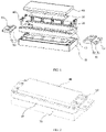
- the elastic component includes a plurality of springs 20. Specifically, an amount of the springs 20 may be eight. As shown in FIG. 1 , the base 10 is provided with a plurality of holes for installing the springs 20, and top ends of the springs 20 are fixedly connected to the backing plate 30. In this embodiment, the eight springs 20 are connected to the bottom of the backing plate 30 in a rectangular array distribution. Specifically, an elastic force of each spring 20 may be arranged to be about 0.4N.
- the flexible pressing mold 40 is arranged as a silicone pressing mold.
- a friction coefficient of the flexible pressing mold 40 may be arranged to be 0.2 to 0.4.
- the flexible pressing mold 40 is made of silica gel, and is coated with a PU (polyurethane).
- the silicone material is soft and easy to deform, which is beneficial for the flexible pressing mold 40 to fully contact with the screen without damaging the screen.
- the arrangement of the PU coating is beneficial to increasing a friction, improving the stability of the laminating apparatus for a curved screen during the laminating process, and preventing the non-uniform laminating force caused by slippage.
Landscapes
- Engineering & Computer Science (AREA)
- Manufacturing & Machinery (AREA)
- Physics & Mathematics (AREA)
- Fluid Mechanics (AREA)
- Lining Or Joining Of Plastics Or The Like (AREA)
- Devices For Indicating Variable Information By Combining Individual Elements (AREA)
- Casting Or Compression Moulding Of Plastics Or The Like (AREA)
- Overhead Projectors And Projection Screens (AREA)
Abstract
Description
- The present disclosure relates to the field of display technologies and, in particular, to a laminating apparatus for a curved screen.
- With the development of display technology, users' display requirements for display screens are gradually diversified. In order to obtain a better visual experience, display screens will gradually develop towards curved surfaces. During a manufacturing process of a curved screen, a screen needs to be laminated on a cover plate. In the prior art, the screen is usually laminated on the cover plate by a laminating apparatus.
- Embodiments of the present disclosure provide a laminating apparatus for a curved screen to solve a problem of a poor laminating effect between a screen and a cover plate in a curved screen.
- In order to achieve the foregoing objective, embodiments of the present disclosure provide the following technical solutions.
- An embodiment of the present disclosure provides a laminating apparatus for a curved screen, including a base, an elastic component, a backing plate and a flexible pressing mold, wherein the backing plate is arranged above the base, the elastic component is connected to the backing plate, the flexible pressing mold covers the backing plate and has a curved surface curving away from the base and adapted to a shape of a screen; and the base includes a main body and two side beams connected to two sides of the main body, the side beams are higher than the main body in a vertical direction, each of the side beams is provided with a groove and a supporting part along a length direction thereof, and two sides of the flexible pressing mold extend outward to cover the two supporting parts and extend into the two grooves.
- The laminating apparatus for a curved screen provided by the embodiments of the present disclosure has the following advantages.
- In the laminating apparatus for a curved screen provided by the embodiments of the present disclosure, a top of the flexible pressing mold is arranged as a curved surface adapted to the shape of the screen, which ensures uniformity of a pressure applied by the flexible pressing mold to the screen; an elastic connection between the backing plate and the base ensures that the flexible pressing mold is fully extended to increase a contacting area between the screen and the flexible pressing mold; an arrangement of the groove and the supporting part on each of the side beams enables edge portions of the flexible pressing mold to extend toward the screen, which increases a pressure applied by the edge portions of the flexible pressing mold to the screen, and makes the screen gradually laminated to a cover plate in a direction from middle to peripheral edges, thereby squeezing out a gas between the screen and the cover plate, reducing a possibility of black spots and bubbles being generated in the curved screen, and solving the problem of the poor laminating effect between the screen and the cover plate.
- As an improvement of the laminating apparatus for a curved screen of an embodiment of the present disclosure, a first chamfer is provided at an edge of the supporting part adjacent to the groove and a second chamfer is provided at an edge of the supporting part adjacent to the main body.
- In addition to the above-described technical problem solved by the present disclosure, technical features constituting the technical solutions, and the beneficial effects brought about by the technical features of these technical solutions, other technical problems that could be solved by the laminating apparatus for a curved screen provided by the embodiments of the present disclosure, other technical features included in the technical solutions and the beneficial effects brought about by these technical features will be further described in detail in the specific implementations.
-
-
FIG. 1 is an exploded view of a laminating apparatus for a curved screen provided according to an embodiment of the present disclosure; -
FIG. 2 is a schematic structural diagram of a laminating apparatus for a curved screen provided according to an embodiment of the present disclosure; -
FIG. 3 is a front view of the laminating apparatus for a curved screen ofFIG. 2 ; -
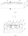
FIG. 4 is a cross-sectional view in a direction of B-B ofFIG. 3 ; -
FIG. 5 is a schematic structural diagram of a flexible pressing mold ofFIG. 1 ; -
FIG. 6 is a left view of the flexible pressing mold ofFIG. 5 ; and -
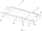
FIG. 7 is a schematic structural diagram of a base ofFIG. 1 . - During a manufacturing process of a curved screen, a laminating apparatus is usually used to laminate the screen on a cover plate. During the lamination, because a pressure to a middle of the screen is greater than a pressure to edges of the screen when the laminating apparatus is in contact with the screen, the pressure to the edges of the screen cannot meet laminating requirements, that is, a laminating force between the curved screen and the cover plate is not uniform, which easily causes black spots, bubbles and other problems in the curved screen, thereby generating a poor lamination. Therefore, a problem of a poor lamination between the screen and the cover plate usually occurs in a display technology.
- In view of the above-mentioned drawbacks, embodiments of the present disclosure provide an improved technical solution. In this technical solution, a laminating apparatus for a curved screen includes a base, an elastic component, a backing plate and a flexible pressing mold. A top of the flexible pressing mold is arranged as a curved surface adapted to a shape of a screen, which ensures uniformity of a pressure applied by the flexible pressing mold to the screen; an elastic connection between the backing plate and the base ensures that the flexible pressing mold is fully extended to increase a contacting area between the screen and the flexible pressing mold; an arrangement of groove and supporting part on each of the side beams enables edge portions of the flexible pressing mold to extend toward the screen, which increases a pressure applied by the edge portions of the flexible pressing mold to the screen, and makes the screen gradually laminated to a cover plate in a direction from middle to peripheral edges, thereby squeezing out a gas between the screen and the cover plate, reducing a possibility of black spots and bubbles being generated in the curved screen, and solving the problem of the poor laminating effect between the screen and the cover plate.
- Reference is made in the following to
FIGS.1-7 . A laminating apparatus for a curved screen provided by an embodiment of the present disclosure includes abase 10, an elastic component, abacking plate 30 and a flexiblepressing mold 40, wherein thebacking plate 30 is arranged above thebase 10, and one end of the elastic component is connected to thebacking plate 30 and the other end of the elastic component is connected to thebase 10. The flexiblepressing mold 40 covers thebacking plate 30, and a top of the flexiblepressing mold 40 is arranged as a curved surface adapted to a shape of a screen. Thebase 10 includes amain body 11 and twoside beams 12 connected to two sides of themain body 11. Theside beams 12 are higher than themain body 11 in a vertical direction. Each of theside beams 12 is provided with agroove 13 and a supportingpart 14 extending along a length direction thereof. Two sides of the flexible pressingmold 40 extend outward to cover the two supportingparts 14 and extend into the twogrooves 13. - The laminating apparatus for a curved screen provided in this embodiment is used for laminating the curved screen to a cover plate. Specifically, during a laminating process, the flexible
pressing mold 40 of the laminating apparatus for a curved screen is in contact with the screen to drive the screen to be laminated to the cover plate. In the laminating apparatus for a curved screen provided in this embodiment, the flexiblepressing mold 40 is used to directly contact with the screen. - In this embodiment, the flexible
pressing mold 40 has characteristics of being soft, easy to deform and easy to extend. Specifically, a material of the flexiblepressing mold 40 may be silicone, rubber, or TPE (Thermoplastic Elastomer), and may also be soft PVC (Polyvinyl chloride). - Since the curved screen is in a curved shape, the top of the flexible
pressing mold 40 is used to fit the screen to be laminated. As shown inFIGS. 5 and 6 , the top of the flexiblepressing mold 40 in this embodiment is arranged as a curved surface adapted to the shape of the screen. Such an arrangement ensures the uniformity of the pressure applied by the flexiblepressing mold 40 to the screen, which can reduce or avoid a possibility of the screen being broken due to a non-uniform pressure, and also improve a tightness of subsequent lamination. - As shown in
FIGS 2 ,3, and 4 , the flexiblepressing mold 40 covers thebacking plate 30. Specifically, the flexiblepressing mold 40 covers a top surface and at least two side surfaces of thebacking plate 30, and since the flexiblepressing mold 40 is easy to extend when a force is applied thereon, the arrangement of the flexiblepressing mold 40 covering thebacking plate 30 in this embodiment can increase a contacting area between the flexiblepressing mold 40 and the screen to be laminated. - Further, the
backing plate 30 and thebase 10 are elastically connected by the elastic component, and the elastic component may be specifically arranged as a plurality of springs, or may be arranged as an elastic rubber. The elastic component provides an elastic force for thebacking plate 30 and the flexiblepressing mold 40 covering thebacking plate 30 during the laminating process of the curved screen, which ensures that the flexiblepressing mold 40 can be fully extended to increase the contacting area between the screen and the flexiblepressing mold 40, thereby making the laminating force between the screen and the cover plate uniform; and at the same time, the elastic component provides a cushion for the lamination, reducing the possibility of the screen being broken. - In addition, the laminating apparatus for a curved screen provided in this embodiment can further include a supporting
platform 70 located below thebase 10. It should be noted that being located below thebase 10 in this embodiment refers to being located at a side of thebase 10 facing away from thebacking plate 30. The supportingplatform 70 is used to place other components required for the laminating process, such as a light source. The above-mentioned elastic component can also be arranged on the supportingplatform 70. Specifically, in this embodiment, themain body 11 of thebase 10 has an opening disposed in the middle thereof, and one end of the elastic component is connected to the supportingplatform 70 and the other end of the elastic component is connected with thebacking plate 30 through the opening of themain body 11 of thebase 10. - In this embodiment, the
base 10 may be made of acrylic. As shown inFIGS. 1 and7 , thebase 10 includes themain body 11 and theside beams 12 located on two sides of themain body 11. Theside beams 12 are fixedly connected to themain body 11. Specifically, theside beams 12 and themain body 11 can be formed as an integrated structure. In the vertical direction, a top of theside beam 12 is higher than a top of themain body 11, and a bottom of theside beam 12 is flush with a bottom of themain body 11. The twoside beams 12 are respectively located on two opposite sides of themain body 11. Further, in this embodiment, a bottom surface of themain body 11 is rectangular, theside beams 12 are arranged on two long sides of themain body 11, and a length of theside beam 12 is equal to a length of the rectangularmain body 11. - On the basis of the above implementations, the
groove 13 on theside beam 12 is arranged in a variety of ways. For example, thegroove 13 may be arranged on theside beam 12 from a top surface of theside beam 12. As another example, as shown inFIG. 7 , theside beam 12 includes a main portion and a protrusion, the protrusion has a width equal to a width of the main portion and a length less than a length of the main portion, and thegroove 13 is extending downward from a top surface of the protrusion. This embodiment does not specifically limit the arrangement of thegroove 13. - The
side beam 12 is also provided with the supportingpart 14 thereon. As shown inFIG. 7 , a part of theside beam 12 between thegroove 13 and themain body 11 forms the supportingpart 14, and the supportingpart 14 is used to support the flexiblepressing mold 40. Specifically, as shown inFIG. 4 , the flexiblepressing mold 40 covers thebacking plate 30, and two sides of the flexiblepressing mold 40 which are adjacent to the side beams 12 respectively extend outwards to cover the tops of the supportingparts 14 and the two sides of the flexiblepressing mold 40 extend downward to form protruding ends, and the protruding ends extend into the twogrooves 13 of the twoside beams 12 so that the flexiblepressing mold 40 is locked to the side beams 12. - Taking the orientation shown in
FIG. 1 as an example for description, when the laminating apparatus for a curved screen provided in this embodiment is in use, the laminating apparatus for a curved screen contacts with the screen and drives the screen to move toward the cover plate; a top of the screen firstly contacts with the cover plate, and the cover plate applies a downward pressure to the screen, that is, a downward pressure is applied to the flexiblepressing mold 40. When the pressure applied to the flexiblepressing mold 40 is equal to an elastic force applied to thebacking plate 30 by the elastic component, edges of the flexiblepressing mold 40 gradually extend toward a position where the screen is located when the edges of the flexiblepressing mold 40 is squeezed by the supportingparts 14 of the side beams 12 of thebase 10, thus, the flexiblepressing mold 40 fully contacts with the screen, and the screen and the cover plate are gradually laminated with each other in a direction from the middle to the periphery. - In summary, in the laminating apparatus for a curved screen provided by the embodiments of the present disclosure, the top of the flexible
pressing mold 40 is adapted to the screen, and the flexiblepressing mold 40 covers thebacking plate 30 and a part of the side beams 12 of thebase 10; the elastic component is arranged between thebacking plate 30 and thebase 10; and thebase 10 is provided with thegrooves 13 which are matched with two sides of the flexiblepressing mold 40, so that the flexiblepressing mold 40 can fully contact with the screen during the laminating process, and the screen is gradually laminated to the cover plate in the direction from the middle to the peripheral edges, thereby squeezing out the gas between the screen and the cover plate, reducing the possibility of black spots and bubbles being generated in the curved screen; and solving the problem of the poor laminating effect between the screen and the cover plate. - On the basis of the foregoing implementations, further, a
first chamfer 15 is provided at an edge of the supportingpart 14 adjacent to thegroove 13 and asecond chamfer 16 is provided at an edge of the supportingpart 14 adjacent to themain body 11. As shown inFIG. 7 , the supportingpart 14 is located between thegroove 13 and themain body 11. Since theside beam 12 is higher than themain body 11 in the vertical direction, the supportingpart 14 has two edges, and one of the two edges is provided with thefirst chamfer 15 and the other one of the two edges is provided with thesecond chamfer 16. In this embodiment, thefirst chamfer 15 and thesecond chamfer 16 are in contact with the flexiblepressing mold 40, respectively. Thefirst chamfer 15 and thesecond chamfer 16 can apply an oblique upward thrust to the flexiblepressing mold 40, so that the edges of the flexiblepressing mold 40 are in full contact with the screen, and thus the edges of the screen and the cover plate are closely laminated with each other. - Correspondingly, as shown in
FIGS. 4 and6 , a part of the flexiblepressing mold 40 which contacts with the two edges of the supportingpart 14 may also be provided withinner chamfers 42. Specifically, theinner chamfer 42 can be arranged to be 45° in order to increase a contacting area between the flexiblepressing mold 40 and thefirst chamfer 15 and a contacting area between the flexiblepressing mold 40 and thesecond chamfer 16. - On the basis of the above-mentioned implementations, preferably, the
first chamfer 15 is arranged as a chamfer with a circular arc surface. As shown inFIG. 7 , an edge of the supportingpart 14 adjacent to thegroove 13 is arranged as a chamfer with a circular arc surface, specifically, a radius of the circle where the circular arc surface is located is 2 mm. A contacting area between the circular arc surface of the chamfer and the flexiblepressing mold 40 is large, which further allows the edges of the flexiblepressing mold 40 to be in full contact with the screen from a plurality of different directions, thus improving the tightness of the lamination between the edges of the screen and the cover plate. - In a possible implementation, the
second chamfer 16 is inclined at 30° or 45° or 60°. Preferably, it is easy to manufacture a chamfer of 45°. Specifically, thesecond chamfer 16 may be a chamfer of 1 mm. - In a possible implementation, each of two sides of the flexible
pressing mold 40 located above thegroove 13 is defined by an arc-shapedside 43. As shown inFIGS. 5 and 6 , two sides of the flexiblepressing mold 40 extend outward and extend into thegrooves 13 of the side beams 12 of thebase 10. The arrangement of the arc-shaped sides being located above thegrooves 13 ensures that during the laminating process, the edges of the flexiblepressing mold 40 gradually contacts with the screen from the middle to the peripheral edge, so that the screen and the cover plate are gradually laminated with each other, and the laminating accuracy is thus improved. Further, the arc-shapedside 43 in this embodiment may be defined by a radius-varied arc, that is, a plurality of arcs with different radii are connected to be the arc-shapedside 43, so as to adapt to a radius-varied edge of the cover plate. - In a possible implementation, the flexible
pressing mold 40 is provided with a pair ofextension parts 41 for covering two sides of thebacking plate 30, and a bottom end of each of theextension parts 41 extends inward in a horizontal direction to contact with a bottom of thebacking plate 30. As shown inFIGS. 4 ,5 and 6 , theextension parts 41 are arranged at a bottom of the flexiblepressing mold 40 and extend toward thebase 10. Theextension parts 41 extend inward to cover the two sides of thebacking plate 30, and the bottom ends of theextension parts 41 are in contact with the base 10 or are locked to thebase 10. The arrangement of theextension parts 41 in this embodiment improves the stability of the covering of the flexiblepressing mold 40. - In a possible implementation, the laminating apparatus for a curved screen provided in this embodiment further includes two
blocks 50. The twoblocks 50 are arranged between the twoside beams 12 and are respectively abutting against two sides of the flexiblepressing mold 40. As shown inFIGS. 2 and3 , theblocks 50 are arranged to clamp the flexiblepressing mold 40. On the basis of the above implementations, the top of the flexiblepressing mold 40 is arranged as a curved surface. When the flexiblepressing mold 40 drives the screen to contact with the cover plate, a middle part of the flexiblepressing mold 40 firstly contacts with the screen, and then an edge part of the flexiblepressing mold 40 contacts with the screen. Theblocks 50 can prevent the flexiblepressing mold 40 from extending in the horizontal direction, so that the flexiblepressing mold 40 extends toward the screen, thereby increasing the pressure applied to the screen by edge parts of the flexiblepressing mold 40, and thus enabling more uniform laminating force between the screen and the cover plate. - In a possible implementation, the
base 10 is provided with a plurality of clampingslots 17 for matching with theblocks 50. In this embodiment, the twoblocks 50 are used to clamp two sides of the flexiblepressing mold 40 to prevent the flexiblepressing mold 40 from extending in the horizontal direction. Thebase 10 is provided with the clampingslots 17 and theblocks 50 are installed in the clampingslots 17. Specifically, theblocks 50 can be connected with the clampingslots 17 throughbolts 60. - In a possible implementation, the
block 50 includes abottom plate 51 and abaffle plate 52, thebottom plate 51 is engaged with the clampingslots 17, and thebaffle plate 52 abuts against the flexiblepressing mold 40. Specifically, structures of the twoblocks 50 may be the same or different. As shown inFIGS. 2 and3 , theblock 50 includes thebottom plate 51 and thebaffle plate 52 arranged perpendicular to thebottom plate 51. On the basis of the above implementations, thebottom plate 51 is engaged with the clampingslots 17 of thebase 10, and the connection therebetween is achieved by connecting parts such asbolts 60 or screws; and an inner side of thebaffle plate 52 is in contact with and abuts against a side surface of the flexiblepressing mold 40. - Taking the orientation shown in
FIG. 1 as an example for description, theblock 50 on the left includes abottom plate 51 and abaffle plate 52 connected to a top surface of thebottom plate 51 in a vertical direction, thebottom plate 51 has a pair of clamping strips extending downwards from two sides of a bottom surface of thebottom plate 51, and the clamping strips are received in the clampingslots 17 of thebase 10, and thebottom plate 51 is provided with connectingholes 53 for thebolts 60 to pass through, the connectingholes 53 penetrate through thebottom plate 51; theblock 50 on the right includes abottom plate 51 and abaffle plate 52 connected to a top surface of thebottom plate 51 in a vertical direction, thebottom plate 51 is received in the clampingslots 17 of thebase 10, and connectingholes 53 for thebolts 60 to pass through sequentially penetrate through thebaffle plate 52 and thebottom plate 51 from a top surface of thebaffle plate 52. The connectinghole 53 may be a threaded hole or a through hole, and correspondingly, thebase 10 is provided with a corresponding through hole or threaded hole. In addition, a part of thebottom plate 51 located at a side of thebaffle plate 52 is also provided with a connection hole for connecting a mounting board. The mounting board is used to support a FPC (flexible circuit board) in a curved display screen to prevent the FPC from sagging or bending during the laminating process. - The elastic component includes a plurality of
springs 20. Specifically, an amount of thesprings 20 may be eight. As shown inFIG. 1 , thebase 10 is provided with a plurality of holes for installing thesprings 20, and top ends of thesprings 20 are fixedly connected to thebacking plate 30. In this embodiment, the eightsprings 20 are connected to the bottom of thebacking plate 30 in a rectangular array distribution. Specifically, an elastic force of eachspring 20 may be arranged to be about 0.4N. - The flexible
pressing mold 40 is arranged as a silicone pressing mold. In this embodiment, a friction coefficient of the flexiblepressing mold 40 may be arranged to be 0.2 to 0.4. Specifically, the flexiblepressing mold 40 is made of silica gel, and is coated with a PU (polyurethane). The silicone material is soft and easy to deform, which is beneficial for the flexiblepressing mold 40 to fully contact with the screen without damaging the screen. The arrangement of the PU coating is beneficial to increasing a friction, improving the stability of the laminating apparatus for a curved screen during the laminating process, and preventing the non-uniform laminating force caused by slippage. - The embodiments or implementations in this specification are described in a progressive manner, each embodiment focuses on the differences from other embodiments, and the same or similar portions between the various embodiments can be referred to each other.
- Finally, it should be noted that the above embodiments are only used to illustrate but not to limit the technical solutions of the present disclosure; although the present disclosure has been described in detail with reference to the foregoing embodiments, those of ordinary skill in the art should understand that the technical solutions recorded in the foregoing embodiments may still be modified, or some or all of the technical features may be equivalently replaced; and these modifications or replacements do not make the essence of the corresponding technical solutions deviate from the scope of the technical solutions of the embodiments of the present disclosure.
Claims (20)
- A laminating apparatus for a curved screen, comprising a base, an elastic component, a backing plate and a flexible pressing mold, wherein:the backing plate is arranged above the base, one end of the elastic component is connected to the backing plate, the flexible pressing mold covers the backing plate, and the flexible pressing mold has a curved surface curving away from the base and adapted to a shape of a screen; andthe base comprises a main body and two side beams connected to two sides of the main body, each of the side beams is provided with a groove and a supporting part extending along a length direction thereof, and two sides of the flexible pressing mold extend outward to cover the two supporting parts and extend into the two grooves.
- The laminating apparatus for a curved screen according to claim 1, wherein a first chamfer is provided at an edge of the supporting part adjacent to the groove and a second chamfer is provided at an edge of the supporting part adjacent to the main body.
- The laminating apparatus for a curved screen according to claim 2, wherein the first chamfer is defined as a chamfer with a circular arc surface.
- The laminating apparatus for a curved screen according to claim 2, wherein the second chamfers is inclined at 30° or 45° or 60°.
- The laminating apparatus for a curved screen according to claim 1, wherein each of two sides of the flexible pressing mold above the groove is defined by an arc-shaped side.
- The laminating apparatus for a curved screen according to claim 1, wherein the flexible pressing mold is provided with a pair of extension parts for covering two sides of the backing plate, and a bottom end of each of the extension parts extends inward in a horizontal direction and contacts with a bottom of the backing plate.
- The laminating apparatus for a curved screen according to claim 1, further comprising two blocks arranged between the two side beams and respectively abutting against two sides of the flexible pressing mold.
- The laminating apparatus for a curved screen according to claim 7, wherein the base is provided with a plurality of clamping slots for cooperating with the blocks.
- The laminating apparatus for a curved screen according to claim 8, wherein each of the blocks comprises a bottom plate engaged with the clamping slot and a baffle plate abutting against the flexible pressing mold.
- The laminating apparatus for a curved screen according to claim 9, wherein the baffle plate is connected to a top surface of the bottom plate in a vertical direction; the bottom plate of one of the two blocks has a pair of clamping strips extending downwards from two sides thereof and received in the clamping slots of the base, and the bottom plate is provided with a plurality of connecting holes penetrating therethrough; and the bottom plate of the other one of the two blocks is received in the clamping slots of the base, and the connecting holes sequentially penetrating through the baffle plate and the bottom plate from a top surface of the baffle plate.
- The laminating apparatus for a curved screen according to claim 1, wherein the flexible pressing mold is provided as a silicone pressing mold, a rubber pressing mold, a TPE pressing mold or a PVC pressing mold.
- The laminating apparatus for a curved screen according to claim 1, wherein the side beams are higher than the main body in a vertical direction.
- The laminating apparatus for a curved screen according to claim 1, wherein the flexible pressing mold covers a top surface and at least two side surfaces of the backing plate.
- The laminating apparatus for a curved screen according to claim 1, wherein the elastic component comprises a plurality of springs or is an elastic rubber.
- The laminating apparatus for a curved screen according to claim 1, wherein the elastic component is connected between the backing plate and the base.
- The laminating apparatus for a curved screen according to claim 1, further comprising a supporting platform located below the base.
- The laminating apparatus for a curved screen according to claim 16, wherein the elastic component is arranged on the supporting platform.
- The laminating apparatus for a curved screen according to claim 16, wherein the main body of the base has an opening disposed in the middle thereof, one end of the elastic component is connected to the supporting platform, and the other end of the elastic component is connected with the backing plate through the opening of the base.
- The laminating apparatus for a curved screen according to claim 1, wherein a bottom of each of the two side beams is flush with a bottom of the main body, and when a bottom surface of the main body is rectangular, the two side beams are arranged on two long sides of the main body and a length of each of the two side beams is equal to a length of the main body which is rectangular.
- The laminating apparatus for a curved screen according to claim 19, wherein the side beams are provided with grooves along the length directions of the respective side beams, and the groove is disposed on the side beam from a top surface of the side beam; or, a protrusion has a width equal to a width of the main portion of the side beam and a length less than a length of the main portion, and the groove is extending downward from a top surface of the protrusion.
Applications Claiming Priority (2)
| Application Number | Priority Date | Filing Date | Title |
|---|---|---|---|
| CN201911142222.6A CN110861290A (en) | 2019-11-20 | 2019-11-20 | Curved surface screen laminating device |
| PCT/CN2020/111807 WO2021098329A1 (en) | 2019-11-20 | 2020-08-27 | Curved screen attaching device |
Publications (3)
| Publication Number | Publication Date |
|---|---|
| EP3998150A1 true EP3998150A1 (en) | 2022-05-18 |
| EP3998150A4 EP3998150A4 (en) | 2022-08-10 |
| EP3998150B1 EP3998150B1 (en) | 2024-03-06 |
Family
ID=69655961
Family Applications (1)
| Application Number | Title | Priority Date | Filing Date |
|---|---|---|---|
| EP20889393.3A Active EP3998150B1 (en) | 2019-11-20 | 2020-08-27 | Curved screen attaching device |
Country Status (6)
| Country | Link |
|---|---|
| US (1) | US11731341B2 (en) |
| EP (1) | EP3998150B1 (en) |
| JP (1) | JP7216868B2 (en) |
| KR (1) | KR102713575B1 (en) |
| CN (2) | CN110861290A (en) |
| WO (1) | WO2021098329A1 (en) |
Families Citing this family (20)
| Publication number | Priority date | Publication date | Assignee | Title |
|---|---|---|---|---|
| KR20200124796A (en) | 2019-04-24 | 2020-11-04 | 삼성디스플레이 주식회사 | Display device manufacturing method, protective film included the display device, and bending panel manufacturing apparatus for manufacturing the protective film |
| CN110861290A (en) * | 2019-11-20 | 2020-03-06 | 云谷(固安)科技有限公司 | Curved surface screen laminating device |
| CN212097892U (en) * | 2020-01-20 | 2020-12-08 | 京东方科技集团股份有限公司 | Flexible display panel laminating device |
| CN111223803A (en) * | 2020-03-18 | 2020-06-02 | 深圳市劲拓自动化设备股份有限公司 | a pressing tool |
| CN111497411B (en) | 2020-04-27 | 2022-04-26 | 昆山国显光电有限公司 | Bonding apparatus and bonding method |
| CN111682128B (en) * | 2020-06-18 | 2023-06-23 | 京东方科技集团股份有限公司 | Curved surface bonding device |
| KR102839872B1 (en) | 2020-09-07 | 2025-07-29 | 삼성디스플레이 주식회사 | Attaching device for display panel and method for fabricating display device |
| CN112345533A (en) * | 2020-10-27 | 2021-02-09 | 惠州市特创电子科技有限公司 | Hole illuminating device and equipment for circuit board |
| CN112606525B (en) | 2020-12-14 | 2023-01-24 | 云谷(固安)科技有限公司 | Bonding device and bonding method |
| CN113257114B (en) * | 2021-05-20 | 2022-06-10 | 武汉华星光电技术有限公司 | Display device and electronic apparatus |
| CN114187833B (en) | 2021-12-10 | 2022-09-27 | 苏州华星光电技术有限公司 | a fitting device |
| CN114454489B (en) * | 2022-02-10 | 2024-04-05 | 京东方科技集团股份有限公司 | Laminating equipment |
| CN114613286A (en) * | 2022-03-23 | 2022-06-10 | 京东方科技集团股份有限公司 | Laminating device of flexible display panel and glass cover plate |
| CN115742529B (en) * | 2022-11-24 | 2024-03-15 | 云谷(固安)科技有限公司 | Support components and fit devices |
| CN115891389B (en) * | 2022-11-24 | 2024-04-23 | 云谷(固安)科技有限公司 | Support components and fitting devices |
| CN115891383B (en) * | 2022-11-24 | 2024-07-16 | 云谷(固安)科技有限公司 | Support components and fitting devices |
| CN116153196B (en) * | 2023-02-28 | 2025-05-27 | 昆山国显光电有限公司 | Display cover plate, display module and electronic terminal |
| CN116659223B (en) * | 2023-06-06 | 2026-03-27 | 苏州桐力光电股份有限公司 | Pressure holding structure, baking fixtures and display screen processing methods |
| CN117577715B (en) * | 2024-01-12 | 2024-05-10 | 秦皇岛博冠科技有限公司 | A laminating machine for curved photovoltaic modules |
| CN117863547B (en) * | 2024-02-01 | 2024-08-27 | 江苏中立方实业有限公司 | Capacitor film laminating device |
Family Cites Families (18)
| Publication number | Priority date | Publication date | Assignee | Title |
|---|---|---|---|---|
| TWI447017B (en) * | 2011-07-15 | 2014-08-01 | chun lin Liu | Adhering jig and an adhering method for screen protector plastic sheets |
| JP6916980B2 (en) | 2015-03-31 | 2021-08-11 | 天馬微電子有限公司 | Display device and manufacturing method of display device |
| JP2017025237A (en) | 2015-07-24 | 2017-02-02 | 旭硝子株式会社 | Transparent curved surface material with adhesive layer, display device, manufacturing method of transparent curved surface material with adhesive layer, and manufacturing method of display device |
| KR102343289B1 (en) * | 2015-08-19 | 2021-12-28 | 삼성디스플레이 주식회사 | Lamination device |
| KR102167504B1 (en) * | 2015-11-05 | 2020-10-20 | 삼성디스플레이 주식회사 | Manufacturing device for display device |
| CN108016655B (en) * | 2016-11-03 | 2021-04-13 | 东莞市冠和光学玻璃有限公司 | A mobile phone cover plate laminating mold and process thereof |
| CN106585045B (en) * | 2016-11-03 | 2018-03-20 | 东莞市冠和光学玻璃有限公司 | Mobile phone cover plate attaching mold and process thereof |
| CN106564268B (en) | 2016-11-08 | 2019-09-24 | 武汉华星光电技术有限公司 | Curved screen laminating apparatus and system |
| CN206345061U (en) * | 2016-11-18 | 2017-07-21 | 深圳市承熹机电设备有限公司 | Application of a surface mould |
| CN107379567B (en) | 2017-07-27 | 2019-10-25 | 昆山国显光电有限公司 | Laminating apparatus and applying method |
| CN207466065U (en) * | 2017-09-25 | 2018-06-08 | 深圳市港星原科技有限公司 | A kind of screening glass is bonded mold with cover board |
| CN207954939U (en) * | 2018-02-09 | 2018-10-12 | 蓝思科技(长沙)有限公司 | Glass film joint tool and glass film laminating apparatus |
| JP7054913B2 (en) | 2018-04-19 | 2022-04-15 | 常陽工学株式会社 | Laminated body manufacturing equipment and method of manufacturing a laminated body using this equipment |
| CN108615464B (en) | 2018-04-20 | 2020-06-23 | 云谷(固安)科技有限公司 | Attaching device and attaching method for special-shaped curved surface cover plate and flexible screen |
| KR102035243B1 (en) * | 2018-05-28 | 2019-10-22 | 주식회사 넵시스 | Apparatus for Laminating Film on Panel Cover and Method thereof |
| CN208881171U (en) * | 2018-07-25 | 2019-05-21 | 惠州比亚迪电子有限公司 | Joint tool and application of a surface jig assembly |
| CN209216462U (en) * | 2019-01-25 | 2019-08-06 | 深圳市骏创科技有限公司 | A kind of screen assembly fitting elastic device and attaching tooling |
| CN110861290A (en) * | 2019-11-20 | 2020-03-06 | 云谷(固安)科技有限公司 | Curved surface screen laminating device |
-
2019
- 2019-11-20 CN CN201911142222.6A patent/CN110861290A/en active Pending
- 2019-11-20 CN CN202511492249.3A patent/CN121083906A/en active Pending
-
2020
- 2020-08-27 WO PCT/CN2020/111807 patent/WO2021098329A1/en not_active Ceased
- 2020-08-27 KR KR1020227001644A patent/KR102713575B1/en active Active
- 2020-08-27 JP JP2022504263A patent/JP7216868B2/en active Active
- 2020-08-27 EP EP20889393.3A patent/EP3998150B1/en active Active
-
2021
- 2021-11-08 US US17/521,657 patent/US11731341B2/en active Active
Also Published As
| Publication number | Publication date |
|---|---|
| KR102713575B1 (en) | 2024-10-11 |
| EP3998150B1 (en) | 2024-03-06 |
| JP2022542564A (en) | 2022-10-05 |
| US11731341B2 (en) | 2023-08-22 |
| WO2021098329A1 (en) | 2021-05-27 |
| US20220063179A1 (en) | 2022-03-03 |
| CN121083906A (en) | 2025-12-09 |
| KR20220013953A (en) | 2022-02-04 |
| EP3998150A4 (en) | 2022-08-10 |
| CN110861290A (en) | 2020-03-06 |
| JP7216868B2 (en) | 2023-02-01 |
Similar Documents
| Publication | Publication Date | Title |
|---|---|---|
| EP3998150B1 (en) | Curved screen attaching device | |
| US11787165B2 (en) | Laminating device and laminating method | |
| US9576510B2 (en) | Display device | |
| KR102529080B1 (en) | Laminating apparatus and laminating method using the same | |
| US9078386B2 (en) | Method for manufacturing display device with panel positioning structure | |
| KR102494018B1 (en) | Laminating device and laminating method using the same | |
| US9220174B2 (en) | Pedestal for flat panel display device and flat panel display device | |
| CN104765196B (en) | Curved surface module and its manufacture method, display device | |
| TWI551204B (en) | Assembly jig and assembly method | |
| US11318664B2 (en) | Adhering device and adhering method | |
| CN105864722B (en) | LED panel light and frame assembly | |
| CN115742529B (en) | Support components and fit devices | |
| CN114509893B (en) | Backlight module and display device | |
| CN118284504A (en) | Laminating equipment and laminating method | |
| KR20190070660A (en) | Lamination apparatus and lamination method using the same for reducing the incidence of oca scratches | |
| CN101604082A (en) | Display device with panel positioning function and manufacturing method thereof | |
| CN108287426B (en) | A liquid crystal module | |
| CN111755630B (en) | Pressing jig, use method of pressing jig and display device | |
| CN110307231B (en) | Laminating equipment | |
| CN211528867U (en) | Backlight module with light guide plate inserted and installed | |
| CN212541789U (en) | Liquid crystal splicing display system | |
| CN216362023U (en) | LED display screen lamp plate drain pan and LED display screen | |
| CN209882198U (en) | FPC flexible circuit board for touch screen | |
| JPH0595137U (en) | Shield clamp | |
| JPH03175427A (en) | liquid crystal display device |
Legal Events
| Date | Code | Title | Description |
|---|---|---|---|
| STAA | Information on the status of an ep patent application or granted ep patent |
Free format text: STATUS: THE INTERNATIONAL PUBLICATION HAS BEEN MADE |
|
| PUAI | Public reference made under article 153(3) epc to a published international application that has entered the european phase |
Free format text: ORIGINAL CODE: 0009012 |
|
| STAA | Information on the status of an ep patent application or granted ep patent |
Free format text: STATUS: REQUEST FOR EXAMINATION WAS MADE |
|
| 17P | Request for examination filed |
Effective date: 20220214 |
|
| AK | Designated contracting states |
Kind code of ref document: A1 Designated state(s): AL AT BE BG CH CY CZ DE DK EE ES FI FR GB GR HR HU IE IS IT LI LT LU LV MC MK MT NL NO PL PT RO RS SE SI SK SM TR |
|
| REG | Reference to a national code |
Ref country code: DE Ref legal event code: R079 Free format text: PREVIOUS MAIN CLASS: B29C0063020000 Ipc: B32B0037100000 Ref document number: 602020027007 Country of ref document: DE |
|
| A4 | Supplementary search report drawn up and despatched |
Effective date: 20220712 |
|
| RIC1 | Information provided on ipc code assigned before grant |
Ipc: G09F 9/30 20060101ALI20220706BHEP Ipc: B29L 31/34 20060101ALI20220706BHEP Ipc: B29C 63/02 20060101ALI20220706BHEP Ipc: B32B 38/18 20060101ALI20220706BHEP Ipc: B32B 37/10 20060101AFI20220706BHEP |
|
| DAV | Request for validation of the european patent (deleted) | ||
| DAX | Request for extension of the european patent (deleted) | ||
| GRAP | Despatch of communication of intention to grant a patent |
Free format text: ORIGINAL CODE: EPIDOSNIGR1 |
|
| STAA | Information on the status of an ep patent application or granted ep patent |
Free format text: STATUS: GRANT OF PATENT IS INTENDED |
|
| RIC1 | Information provided on ipc code assigned before grant |
Ipc: G09F 9/30 20060101ALI20230616BHEP Ipc: B29L 31/34 20060101ALI20230616BHEP Ipc: B29C 63/02 20060101ALI20230616BHEP Ipc: B32B 38/18 20060101ALI20230616BHEP Ipc: B32B 37/10 20060101AFI20230616BHEP |
|
| INTG | Intention to grant announced |
Effective date: 20230712 |
|
| GRAJ | Information related to disapproval of communication of intention to grant by the applicant or resumption of examination proceedings by the epo deleted |
Free format text: ORIGINAL CODE: EPIDOSDIGR1 |
|
| STAA | Information on the status of an ep patent application or granted ep patent |
Free format text: STATUS: REQUEST FOR EXAMINATION WAS MADE |
|
| GRAP | Despatch of communication of intention to grant a patent |
Free format text: ORIGINAL CODE: EPIDOSNIGR1 |
|
| STAA | Information on the status of an ep patent application or granted ep patent |
Free format text: STATUS: GRANT OF PATENT IS INTENDED |
|
| INTC | Intention to grant announced (deleted) | ||
| INTG | Intention to grant announced |
Effective date: 20231204 |
|
| GRAS | Grant fee paid |
Free format text: ORIGINAL CODE: EPIDOSNIGR3 |
|
| GRAA | (expected) grant |
Free format text: ORIGINAL CODE: 0009210 |
|
| STAA | Information on the status of an ep patent application or granted ep patent |
Free format text: STATUS: THE PATENT HAS BEEN GRANTED |
|
| AK | Designated contracting states |
Kind code of ref document: B1 Designated state(s): AL AT BE BG CH CY CZ DE DK EE ES FI FR GB GR HR HU IE IS IT LI LT LU LV MC MK MT NL NO PL PT RO RS SE SI SK SM TR |
|
| REG | Reference to a national code |
Ref country code: CH Ref legal event code: EP |
|
| REG | Reference to a national code |
Ref country code: IE Ref legal event code: FG4D |
|
| REG | Reference to a national code |
Ref country code: DE Ref legal event code: R096 Ref document number: 602020027007 Country of ref document: DE |
|
| REG | Reference to a national code |
Ref country code: LT Ref legal event code: MG9D |
|
| PG25 | Lapsed in a contracting state [announced via postgrant information from national office to epo] |
Ref country code: LT Free format text: LAPSE BECAUSE OF FAILURE TO SUBMIT A TRANSLATION OF THE DESCRIPTION OR TO PAY THE FEE WITHIN THE PRESCRIBED TIME-LIMIT Effective date: 20240306 |
|
| REG | Reference to a national code |
Ref country code: NL Ref legal event code: MP Effective date: 20240306 |
|
| PG25 | Lapsed in a contracting state [announced via postgrant information from national office to epo] |
Ref country code: GR Free format text: LAPSE BECAUSE OF FAILURE TO SUBMIT A TRANSLATION OF THE DESCRIPTION OR TO PAY THE FEE WITHIN THE PRESCRIBED TIME-LIMIT Effective date: 20240607 |
|
| PG25 | Lapsed in a contracting state [announced via postgrant information from national office to epo] |
Ref country code: HR Free format text: LAPSE BECAUSE OF FAILURE TO SUBMIT A TRANSLATION OF THE DESCRIPTION OR TO PAY THE FEE WITHIN THE PRESCRIBED TIME-LIMIT Effective date: 20240306 Ref country code: RS Free format text: LAPSE BECAUSE OF FAILURE TO SUBMIT A TRANSLATION OF THE DESCRIPTION OR TO PAY THE FEE WITHIN THE PRESCRIBED TIME-LIMIT Effective date: 20240606 |
|
| PG25 | Lapsed in a contracting state [announced via postgrant information from national office to epo] |
Ref country code: ES Free format text: LAPSE BECAUSE OF FAILURE TO SUBMIT A TRANSLATION OF THE DESCRIPTION OR TO PAY THE FEE WITHIN THE PRESCRIBED TIME-LIMIT Effective date: 20240306 |
|
| PG25 | Lapsed in a contracting state [announced via postgrant information from national office to epo] |
Ref country code: RS Free format text: LAPSE BECAUSE OF FAILURE TO SUBMIT A TRANSLATION OF THE DESCRIPTION OR TO PAY THE FEE WITHIN THE PRESCRIBED TIME-LIMIT Effective date: 20240606 Ref country code: NO Free format text: LAPSE BECAUSE OF FAILURE TO SUBMIT A TRANSLATION OF THE DESCRIPTION OR TO PAY THE FEE WITHIN THE PRESCRIBED TIME-LIMIT Effective date: 20240606 Ref country code: LT Free format text: LAPSE BECAUSE OF FAILURE TO SUBMIT A TRANSLATION OF THE DESCRIPTION OR TO PAY THE FEE WITHIN THE PRESCRIBED TIME-LIMIT Effective date: 20240306 Ref country code: HR Free format text: LAPSE BECAUSE OF FAILURE TO SUBMIT A TRANSLATION OF THE DESCRIPTION OR TO PAY THE FEE WITHIN THE PRESCRIBED TIME-LIMIT Effective date: 20240306 Ref country code: GR Free format text: LAPSE BECAUSE OF FAILURE TO SUBMIT A TRANSLATION OF THE DESCRIPTION OR TO PAY THE FEE WITHIN THE PRESCRIBED TIME-LIMIT Effective date: 20240607 Ref country code: FI Free format text: LAPSE BECAUSE OF FAILURE TO SUBMIT A TRANSLATION OF THE DESCRIPTION OR TO PAY THE FEE WITHIN THE PRESCRIBED TIME-LIMIT Effective date: 20240306 Ref country code: ES Free format text: LAPSE BECAUSE OF FAILURE TO SUBMIT A TRANSLATION OF THE DESCRIPTION OR TO PAY THE FEE WITHIN THE PRESCRIBED TIME-LIMIT Effective date: 20240306 Ref country code: BG Free format text: LAPSE BECAUSE OF FAILURE TO SUBMIT A TRANSLATION OF THE DESCRIPTION OR TO PAY THE FEE WITHIN THE PRESCRIBED TIME-LIMIT Effective date: 20240306 |
|
| REG | Reference to a national code |
Ref country code: AT Ref legal event code: MK05 Ref document number: 1663110 Country of ref document: AT Kind code of ref document: T Effective date: 20240306 |
|
| PG25 | Lapsed in a contracting state [announced via postgrant information from national office to epo] |
Ref country code: SE Free format text: LAPSE BECAUSE OF FAILURE TO SUBMIT A TRANSLATION OF THE DESCRIPTION OR TO PAY THE FEE WITHIN THE PRESCRIBED TIME-LIMIT Effective date: 20240306 Ref country code: LV Free format text: LAPSE BECAUSE OF FAILURE TO SUBMIT A TRANSLATION OF THE DESCRIPTION OR TO PAY THE FEE WITHIN THE PRESCRIBED TIME-LIMIT Effective date: 20240306 |
|
| PG25 | Lapsed in a contracting state [announced via postgrant information from national office to epo] |
Ref country code: NL Free format text: LAPSE BECAUSE OF FAILURE TO SUBMIT A TRANSLATION OF THE DESCRIPTION OR TO PAY THE FEE WITHIN THE PRESCRIBED TIME-LIMIT Effective date: 20240306 |
|
| PG25 | Lapsed in a contracting state [announced via postgrant information from national office to epo] |
Ref country code: NL Free format text: LAPSE BECAUSE OF FAILURE TO SUBMIT A TRANSLATION OF THE DESCRIPTION OR TO PAY THE FEE WITHIN THE PRESCRIBED TIME-LIMIT Effective date: 20240306 |
|
| PG25 | Lapsed in a contracting state [announced via postgrant information from national office to epo] |
Ref country code: IS Free format text: LAPSE BECAUSE OF FAILURE TO SUBMIT A TRANSLATION OF THE DESCRIPTION OR TO PAY THE FEE WITHIN THE PRESCRIBED TIME-LIMIT Effective date: 20240706 |
|
| PG25 | Lapsed in a contracting state [announced via postgrant information from national office to epo] |
Ref country code: SM Free format text: LAPSE BECAUSE OF FAILURE TO SUBMIT A TRANSLATION OF THE DESCRIPTION OR TO PAY THE FEE WITHIN THE PRESCRIBED TIME-LIMIT Effective date: 20240306 Ref country code: PT Free format text: LAPSE BECAUSE OF FAILURE TO SUBMIT A TRANSLATION OF THE DESCRIPTION OR TO PAY THE FEE WITHIN THE PRESCRIBED TIME-LIMIT Effective date: 20240708 |
|
| PG25 | Lapsed in a contracting state [announced via postgrant information from national office to epo] |
Ref country code: CZ Free format text: LAPSE BECAUSE OF FAILURE TO SUBMIT A TRANSLATION OF THE DESCRIPTION OR TO PAY THE FEE WITHIN THE PRESCRIBED TIME-LIMIT Effective date: 20240306 Ref country code: EE Free format text: LAPSE BECAUSE OF FAILURE TO SUBMIT A TRANSLATION OF THE DESCRIPTION OR TO PAY THE FEE WITHIN THE PRESCRIBED TIME-LIMIT Effective date: 20240306 |
|
| PG25 | Lapsed in a contracting state [announced via postgrant information from national office to epo] |
Ref country code: AT Free format text: LAPSE BECAUSE OF FAILURE TO SUBMIT A TRANSLATION OF THE DESCRIPTION OR TO PAY THE FEE WITHIN THE PRESCRIBED TIME-LIMIT Effective date: 20240306 |
|
| PG25 | Lapsed in a contracting state [announced via postgrant information from national office to epo] |
Ref country code: PL Free format text: LAPSE BECAUSE OF FAILURE TO SUBMIT A TRANSLATION OF THE DESCRIPTION OR TO PAY THE FEE WITHIN THE PRESCRIBED TIME-LIMIT Effective date: 20240306 |
|
| PG25 | Lapsed in a contracting state [announced via postgrant information from national office to epo] |
Ref country code: SK Free format text: LAPSE BECAUSE OF FAILURE TO SUBMIT A TRANSLATION OF THE DESCRIPTION OR TO PAY THE FEE WITHIN THE PRESCRIBED TIME-LIMIT Effective date: 20240306 |
|
| PG25 | Lapsed in a contracting state [announced via postgrant information from national office to epo] |
Ref country code: SM Free format text: LAPSE BECAUSE OF FAILURE TO SUBMIT A TRANSLATION OF THE DESCRIPTION OR TO PAY THE FEE WITHIN THE PRESCRIBED TIME-LIMIT Effective date: 20240306 Ref country code: SK Free format text: LAPSE BECAUSE OF FAILURE TO SUBMIT A TRANSLATION OF THE DESCRIPTION OR TO PAY THE FEE WITHIN THE PRESCRIBED TIME-LIMIT Effective date: 20240306 Ref country code: RO Free format text: LAPSE BECAUSE OF FAILURE TO SUBMIT A TRANSLATION OF THE DESCRIPTION OR TO PAY THE FEE WITHIN THE PRESCRIBED TIME-LIMIT Effective date: 20240306 Ref country code: PT Free format text: LAPSE BECAUSE OF FAILURE TO SUBMIT A TRANSLATION OF THE DESCRIPTION OR TO PAY THE FEE WITHIN THE PRESCRIBED TIME-LIMIT Effective date: 20240708 Ref country code: PL Free format text: LAPSE BECAUSE OF FAILURE TO SUBMIT A TRANSLATION OF THE DESCRIPTION OR TO PAY THE FEE WITHIN THE PRESCRIBED TIME-LIMIT Effective date: 20240306 Ref country code: IS Free format text: LAPSE BECAUSE OF FAILURE TO SUBMIT A TRANSLATION OF THE DESCRIPTION OR TO PAY THE FEE WITHIN THE PRESCRIBED TIME-LIMIT Effective date: 20240706 Ref country code: EE Free format text: LAPSE BECAUSE OF FAILURE TO SUBMIT A TRANSLATION OF THE DESCRIPTION OR TO PAY THE FEE WITHIN THE PRESCRIBED TIME-LIMIT Effective date: 20240306 Ref country code: CZ Free format text: LAPSE BECAUSE OF FAILURE TO SUBMIT A TRANSLATION OF THE DESCRIPTION OR TO PAY THE FEE WITHIN THE PRESCRIBED TIME-LIMIT Effective date: 20240306 Ref country code: AT Free format text: LAPSE BECAUSE OF FAILURE TO SUBMIT A TRANSLATION OF THE DESCRIPTION OR TO PAY THE FEE WITHIN THE PRESCRIBED TIME-LIMIT Effective date: 20240306 |
|
| PG25 | Lapsed in a contracting state [announced via postgrant information from national office to epo] |
Ref country code: IT Free format text: LAPSE BECAUSE OF FAILURE TO SUBMIT A TRANSLATION OF THE DESCRIPTION OR TO PAY THE FEE WITHIN THE PRESCRIBED TIME-LIMIT Effective date: 20240306 |
|
| REG | Reference to a national code |
Ref country code: DE Ref legal event code: R097 Ref document number: 602020027007 Country of ref document: DE |
|
| PG25 | Lapsed in a contracting state [announced via postgrant information from national office to epo] |
Ref country code: IT Free format text: LAPSE BECAUSE OF FAILURE TO SUBMIT A TRANSLATION OF THE DESCRIPTION OR TO PAY THE FEE WITHIN THE PRESCRIBED TIME-LIMIT Effective date: 20240306 |
|
| PLBE | No opposition filed within time limit |
Free format text: ORIGINAL CODE: 0009261 |
|
| STAA | Information on the status of an ep patent application or granted ep patent |
Free format text: STATUS: NO OPPOSITION FILED WITHIN TIME LIMIT |
|
| PG25 | Lapsed in a contracting state [announced via postgrant information from national office to epo] |
Ref country code: DK Free format text: LAPSE BECAUSE OF FAILURE TO SUBMIT A TRANSLATION OF THE DESCRIPTION OR TO PAY THE FEE WITHIN THE PRESCRIBED TIME-LIMIT Effective date: 20240306 |
|
| PG25 | Lapsed in a contracting state [announced via postgrant information from national office to epo] |
Ref country code: DK Free format text: LAPSE BECAUSE OF FAILURE TO SUBMIT A TRANSLATION OF THE DESCRIPTION OR TO PAY THE FEE WITHIN THE PRESCRIBED TIME-LIMIT Effective date: 20240306 |
|
| 26N | No opposition filed |
Effective date: 20241209 |
|
| REG | Reference to a national code |
Ref country code: CH Ref legal event code: PL |
|
| PG25 | Lapsed in a contracting state [announced via postgrant information from national office to epo] |
Ref country code: LU Free format text: LAPSE BECAUSE OF NON-PAYMENT OF DUE FEES Effective date: 20240827 |
|
| PG25 | Lapsed in a contracting state [announced via postgrant information from national office to epo] |
Ref country code: MC Free format text: LAPSE BECAUSE OF FAILURE TO SUBMIT A TRANSLATION OF THE DESCRIPTION OR TO PAY THE FEE WITHIN THE PRESCRIBED TIME-LIMIT Effective date: 20240306 Ref country code: CH Free format text: LAPSE BECAUSE OF NON-PAYMENT OF DUE FEES Effective date: 20240831 Ref country code: SI Free format text: LAPSE BECAUSE OF FAILURE TO SUBMIT A TRANSLATION OF THE DESCRIPTION OR TO PAY THE FEE WITHIN THE PRESCRIBED TIME-LIMIT Effective date: 20240306 |
|
| REG | Reference to a national code |
Ref country code: BE Ref legal event code: MM Effective date: 20240831 |
|
| PG25 | Lapsed in a contracting state [announced via postgrant information from national office to epo] |
Ref country code: BE Free format text: LAPSE BECAUSE OF NON-PAYMENT OF DUE FEES Effective date: 20240831 |
|
| PG25 | Lapsed in a contracting state [announced via postgrant information from national office to epo] |
Ref country code: IE Free format text: LAPSE BECAUSE OF NON-PAYMENT OF DUE FEES Effective date: 20240827 |
|
| PGFP | Annual fee paid to national office [announced via postgrant information from national office to epo] |
Ref country code: DE Payment date: 20250812 Year of fee payment: 6 |
|
| PGFP | Annual fee paid to national office [announced via postgrant information from national office to epo] |
Ref country code: GB Payment date: 20250826 Year of fee payment: 6 |
|
| PGFP | Annual fee paid to national office [announced via postgrant information from national office to epo] |
Ref country code: FR Payment date: 20250828 Year of fee payment: 6 |
|
| PG25 | Lapsed in a contracting state [announced via postgrant information from national office to epo] |
Ref country code: CY Free format text: LAPSE BECAUSE OF FAILURE TO SUBMIT A TRANSLATION OF THE DESCRIPTION OR TO PAY THE FEE WITHIN THE PRESCRIBED TIME-LIMIT; INVALID AB INITIO Effective date: 20200827 |
|
| PG25 | Lapsed in a contracting state [announced via postgrant information from national office to epo] |
Ref country code: HU Free format text: LAPSE BECAUSE OF FAILURE TO SUBMIT A TRANSLATION OF THE DESCRIPTION OR TO PAY THE FEE WITHIN THE PRESCRIBED TIME-LIMIT; INVALID AB INITIO Effective date: 20200827 |