EP3998101A1 - Medical device, extracorporeal unit, power transmission sheet, and medical instrument - Google Patents
Medical device, extracorporeal unit, power transmission sheet, and medical instrument Download PDFInfo
- Publication number
- EP3998101A1 EP3998101A1 EP20857565.4A EP20857565A EP3998101A1 EP 3998101 A1 EP3998101 A1 EP 3998101A1 EP 20857565 A EP20857565 A EP 20857565A EP 3998101 A1 EP3998101 A1 EP 3998101A1
- Authority
- EP
- European Patent Office
- Prior art keywords
- unit
- power
- coil
- light emitting
- soft portion
- Prior art date
- Legal status (The legal status is an assumption and is not a legal conclusion. Google has not performed a legal analysis and makes no representation as to the accuracy of the status listed.)
- Granted
Links
Images












Classifications
-
- A—HUMAN NECESSITIES
- A61—MEDICAL OR VETERINARY SCIENCE; HYGIENE
- A61M—DEVICES FOR INTRODUCING MEDIA INTO, OR ONTO, THE BODY; DEVICES FOR TRANSDUCING BODY MEDIA OR FOR TAKING MEDIA FROM THE BODY; DEVICES FOR PRODUCING OR ENDING SLEEP OR STUPOR
- A61M39/00—Tubes, tube connectors, tube couplings, valves, access sites or the like, specially adapted for medical use
- A61M39/02—Access sites
- A61M39/0208—Subcutaneous access sites
-
- A—HUMAN NECESSITIES
- A61—MEDICAL OR VETERINARY SCIENCE; HYGIENE
- A61B—DIAGNOSIS; SURGERY; IDENTIFICATION
- A61B5/00—Measuring for diagnostic purposes; Identification of persons
- A61B5/06—Devices, other than using radiation, for detecting or locating foreign bodies ; Determining position of diagnostic devices within or on the body of the patient
-
- A—HUMAN NECESSITIES
- A61—MEDICAL OR VETERINARY SCIENCE; HYGIENE
- A61B—DIAGNOSIS; SURGERY; IDENTIFICATION
- A61B5/00—Measuring for diagnostic purposes; Identification of persons
- A61B5/05—Detecting, measuring or recording for diagnosis by means of electric currents or magnetic fields; Measuring using microwaves or radio waves
-
- A—HUMAN NECESSITIES
- A61—MEDICAL OR VETERINARY SCIENCE; HYGIENE
- A61B—DIAGNOSIS; SURGERY; IDENTIFICATION
- A61B5/00—Measuring for diagnostic purposes; Identification of persons
- A61B5/06—Devices, other than using radiation, for detecting or locating foreign bodies ; Determining position of diagnostic devices within or on the body of the patient
- A61B5/061—Determining position of a probe within the body employing means separate from the probe, e.g. sensing internal probe position employing impedance electrodes on the surface of the body
-
- A—HUMAN NECESSITIES
- A61—MEDICAL OR VETERINARY SCIENCE; HYGIENE
- A61M—DEVICES FOR INTRODUCING MEDIA INTO, OR ONTO, THE BODY; DEVICES FOR TRANSDUCING BODY MEDIA OR FOR TAKING MEDIA FROM THE BODY; DEVICES FOR PRODUCING OR ENDING SLEEP OR STUPOR
- A61M39/00—Tubes, tube connectors, tube couplings, valves, access sites or the like, specially adapted for medical use
- A61M39/02—Access sites
- A61M39/0247—Transcutaneous or percutaneous access sites to the inside of the body
-
- A—HUMAN NECESSITIES
- A61—MEDICAL OR VETERINARY SCIENCE; HYGIENE
- A61M—DEVICES FOR INTRODUCING MEDIA INTO, OR ONTO, THE BODY; DEVICES FOR TRANSDUCING BODY MEDIA OR FOR TAKING MEDIA FROM THE BODY; DEVICES FOR PRODUCING OR ENDING SLEEP OR STUPOR
- A61M39/00—Tubes, tube connectors, tube couplings, valves, access sites or the like, specially adapted for medical use
- A61M39/02—Access sites
- A61M39/04—Access sites having pierceable self-sealing members
-
- A—HUMAN NECESSITIES
- A61—MEDICAL OR VETERINARY SCIENCE; HYGIENE
- A61M—DEVICES FOR INTRODUCING MEDIA INTO, OR ONTO, THE BODY; DEVICES FOR TRANSDUCING BODY MEDIA OR FOR TAKING MEDIA FROM THE BODY; DEVICES FOR PRODUCING OR ENDING SLEEP OR STUPOR
- A61M5/00—Devices for bringing media into the body in a subcutaneous, intra-vascular or intramuscular way; Accessories therefor, e.g. filling or cleaning devices, arm rests
- A61M5/14—Infusion devices, e.g. infusing by gravity; Blood infusion; Accessories therefor
- A61M5/142—Pressure infusion, e.g. using pumps
- A61M5/14244—Pressure infusion, e.g. using pumps adapted to be carried by the patient, e.g. portable on the body
- A61M5/14276—Pressure infusion, e.g. using pumps adapted to be carried by the patient, e.g. portable on the body specially adapted for implantation
-
- A—HUMAN NECESSITIES
- A61—MEDICAL OR VETERINARY SCIENCE; HYGIENE
- A61N—ELECTROTHERAPY; MAGNETOTHERAPY; RADIATION THERAPY; ULTRASOUND THERAPY
- A61N1/00—Electrotherapy; Circuits therefor
- A61N1/18—Applying electric currents by contact electrodes
- A61N1/32—Applying electric currents by contact electrodes alternating or intermittent currents
- A61N1/36—Applying electric currents by contact electrodes alternating or intermittent currents for stimulation
- A61N1/372—Arrangements in connection with the implantation of stimulators
- A61N1/37211—Means for communicating with stimulators
- A61N1/37217—Means for communicating with stimulators characterised by the communication link, e.g. acoustic or tactile
- A61N1/37223—Circuits for electromagnetic coupling
- A61N1/37229—Shape or location of the implanted or external antenna
-
- A—HUMAN NECESSITIES
- A61—MEDICAL OR VETERINARY SCIENCE; HYGIENE
- A61N—ELECTROTHERAPY; MAGNETOTHERAPY; RADIATION THERAPY; ULTRASOUND THERAPY
- A61N1/00—Electrotherapy; Circuits therefor
- A61N1/18—Applying electric currents by contact electrodes
- A61N1/32—Applying electric currents by contact electrodes alternating or intermittent currents
- A61N1/36—Applying electric currents by contact electrodes alternating or intermittent currents for stimulation
- A61N1/372—Arrangements in connection with the implantation of stimulators
- A61N1/378—Electrical supply
- A61N1/3787—Electrical supply from an external energy source
-
- H—ELECTRICITY
- H01—ELECTRIC ELEMENTS
- H01F—MAGNETS; INDUCTANCES; TRANSFORMERS; SELECTION OF MATERIALS FOR THEIR MAGNETIC PROPERTIES
- H01F38/00—Adaptations of transformers or inductances for specific applications or functions
- H01F38/14—Inductive couplings
-
- H—ELECTRICITY
- H02—GENERATION; CONVERSION OR DISTRIBUTION OF ELECTRIC POWER
- H02J—ELECTRIC POWER NETWORKS; CIRCUIT ARRANGEMENTS OR SYSTEMS FOR SUPPLYING OR DISTRIBUTING ELECTRIC POWER; SYSTEMS FOR STORING ELECTRIC ENERGY
- H02J50/00—Circuit arrangements or systems for wireless supply or distribution of electric power
- H02J50/10—Circuit arrangements or systems for wireless supply or distribution of electric power using inductive coupling
-
- H—ELECTRICITY
- H02—GENERATION; CONVERSION OR DISTRIBUTION OF ELECTRIC POWER
- H02J—ELECTRIC POWER NETWORKS; CIRCUIT ARRANGEMENTS OR SYSTEMS FOR SUPPLYING OR DISTRIBUTING ELECTRIC POWER; SYSTEMS FOR STORING ELECTRIC ENERGY
- H02J50/00—Circuit arrangements or systems for wireless supply or distribution of electric power
- H02J50/40—Circuit arrangements or systems for wireless supply or distribution of electric power using two or more transmitting or receiving devices
- H02J50/402—Circuit arrangements or systems for wireless supply or distribution of electric power using two or more transmitting or receiving devices the two or more transmitting or the two or more receiving devices being integrated in the same unit, e.g. power mats with several coils or antennas with several sub-antennas
-
- H—ELECTRICITY
- H02—GENERATION; CONVERSION OR DISTRIBUTION OF ELECTRIC POWER
- H02J—ELECTRIC POWER NETWORKS; CIRCUIT ARRANGEMENTS OR SYSTEMS FOR SUPPLYING OR DISTRIBUTING ELECTRIC POWER; SYSTEMS FOR STORING ELECTRIC ENERGY
- H02J50/00—Circuit arrangements or systems for wireless supply or distribution of electric power
- H02J50/90—Circuit arrangements or systems for wireless supply or distribution of electric power involving detection or optimisation of position, e.g. alignment
-
- A—HUMAN NECESSITIES
- A61—MEDICAL OR VETERINARY SCIENCE; HYGIENE
- A61M—DEVICES FOR INTRODUCING MEDIA INTO, OR ONTO, THE BODY; DEVICES FOR TRANSDUCING BODY MEDIA OR FOR TAKING MEDIA FROM THE BODY; DEVICES FOR PRODUCING OR ENDING SLEEP OR STUPOR
- A61M39/00—Tubes, tube connectors, tube couplings, valves, access sites or the like, specially adapted for medical use
- A61M39/02—Access sites
- A61M2039/0205—Access sites for injecting media
-
- A—HUMAN NECESSITIES
- A61—MEDICAL OR VETERINARY SCIENCE; HYGIENE
- A61M—DEVICES FOR INTRODUCING MEDIA INTO, OR ONTO, THE BODY; DEVICES FOR TRANSDUCING BODY MEDIA OR FOR TAKING MEDIA FROM THE BODY; DEVICES FOR PRODUCING OR ENDING SLEEP OR STUPOR
- A61M39/00—Tubes, tube connectors, tube couplings, valves, access sites or the like, specially adapted for medical use
- A61M39/02—Access sites
- A61M39/0208—Subcutaneous access sites
- A61M2039/0238—Subcutaneous access sites having means for locating the implanted device to insure proper injection, e.g. radio-emitter, protuberances, radio-opaque markers
-
- A—HUMAN NECESSITIES
- A61—MEDICAL OR VETERINARY SCIENCE; HYGIENE
- A61M—DEVICES FOR INTRODUCING MEDIA INTO, OR ONTO, THE BODY; DEVICES FOR TRANSDUCING BODY MEDIA OR FOR TAKING MEDIA FROM THE BODY; DEVICES FOR PRODUCING OR ENDING SLEEP OR STUPOR
- A61M2205/00—General characteristics of the apparatus
- A61M2205/05—General characteristics of the apparatus combined with other kinds of therapy
- A61M2205/051—General characteristics of the apparatus combined with other kinds of therapy with radiation therapy
- A61M2205/052—General characteristics of the apparatus combined with other kinds of therapy with radiation therapy infrared
-
- A—HUMAN NECESSITIES
- A61—MEDICAL OR VETERINARY SCIENCE; HYGIENE
- A61M—DEVICES FOR INTRODUCING MEDIA INTO, OR ONTO, THE BODY; DEVICES FOR TRANSDUCING BODY MEDIA OR FOR TAKING MEDIA FROM THE BODY; DEVICES FOR PRODUCING OR ENDING SLEEP OR STUPOR
- A61M2205/00—General characteristics of the apparatus
- A61M2205/58—Means for facilitating use, e.g. by people with impaired vision
- A61M2205/581—Means for facilitating use, e.g. by people with impaired vision by audible feedback
-
- A—HUMAN NECESSITIES
- A61—MEDICAL OR VETERINARY SCIENCE; HYGIENE
- A61M—DEVICES FOR INTRODUCING MEDIA INTO, OR ONTO, THE BODY; DEVICES FOR TRANSDUCING BODY MEDIA OR FOR TAKING MEDIA FROM THE BODY; DEVICES FOR PRODUCING OR ENDING SLEEP OR STUPOR
- A61M2205/00—General characteristics of the apparatus
- A61M2205/58—Means for facilitating use, e.g. by people with impaired vision
- A61M2205/583—Means for facilitating use, e.g. by people with impaired vision by visual feedback
-
- A—HUMAN NECESSITIES
- A61—MEDICAL OR VETERINARY SCIENCE; HYGIENE
- A61M—DEVICES FOR INTRODUCING MEDIA INTO, OR ONTO, THE BODY; DEVICES FOR TRANSDUCING BODY MEDIA OR FOR TAKING MEDIA FROM THE BODY; DEVICES FOR PRODUCING OR ENDING SLEEP OR STUPOR
- A61M2205/00—General characteristics of the apparatus
- A61M2205/82—Internal energy supply devices
- A61M2205/8237—Charging means
- A61M2205/8243—Charging means by induction
-
- H—ELECTRICITY
- H02—GENERATION; CONVERSION OR DISTRIBUTION OF ELECTRIC POWER
- H02J—ELECTRIC POWER NETWORKS; CIRCUIT ARRANGEMENTS OR SYSTEMS FOR SUPPLYING OR DISTRIBUTING ELECTRIC POWER; SYSTEMS FOR STORING ELECTRIC ENERGY
- H02J2105/00—Networks for supplying or distributing electric power characterised by their spatial reach or by the load
- H02J2105/40—Networks for supplying or distributing electric power characterised by their spatial reach or by the load characterised by the loads connecting to the networks or being supplied by the networks
- H02J2105/46—Medical devices, medical implants or life supporting devices
Definitions
- the present disclosure relates to a medical device for detecting a position of an implantable medical instrument for use within the body of a subject, an extracorporeal unit, a power transmission sheet, and the medical instrument.
- a body-implantable medical device in which a body portion of a medical instrument is implanted into a body is used for charging a medicinal solution into the body.
- This medical instrument reduces the burden on patients who need frequent injections for charging a medicinal solution.
- Such a medical instrument has a soft portion through which an injection needle is inserted into the body portion. This soft portion is made of, for example, silicone rubber or other materials. With the medical instrument, a medicinal solution is injected into a medicinal solution container through the soft portion. The medicinal solution is transported through a catheter to blood vessels.
- a medical instrument which includes a soft portion provided by mixing a luminescent material that emits near-infrared fluorescence by irradiation with near-infrared excitation light with a resin material, by applying the technique proposed in Patent Document 1.
- a medical instrument there is a possibility of the position of the soft portion being able to be visually specified by converting the near-infrared fluorescence into visible light.
- Patent Document 1 Japanese Patent No. 5958922
- Exemplary embodiments of the present disclosure provide a medical device that makes it possible to easily confirm a predetermined location in an implantable medical instrument for use in a body, an extracorporeal unit, a power transmission sheet, and the medical instrument.
- An exemplary embodiment of the present invention provides a medical device including: a power transmission unit including a second coil that transmits power in a non-contact manner; a power receiving unit including a first coil that receives the power transmitted from the power transmission unit; and an implantable medical instrument for use in a body, the implantable medical instrument including the power receiving unit, the implantable medical instrument including: a notification unit including a plurality of light emitting units which notify that a relative positional relationship between the power transmission unit and the power receiving unit has reached a predetermined state along with a movement of the power transmission unit, by emitting light using the power received by the power receiving unit; and a soft portion for insertion of an injection needle, in which the plurality of light emitting units is arranged along an outer edge of the soft portion.
- the power receiving unit includes a plurality of power receiving units, and the plurality of light emitting units each emit light using power received by a corresponding one of the plurality of power receiving units connected thereto.
- the plurality of light emitting units share the power receiving unit, and emit light using the power received by the power receiving unit.
- the notification unit includes a first light intensity in a brightest location in a circle having a first radius smaller than an inner diameter of the soft portion, and a second light intensity in a brightest location outside a circle having a second radius larger than the first radius, in which the first light intensity and second light intensity differ from each other.
- the power transmission unit includes a plate-shaped sheet portion
- the plate-shaped sheet portion includes a second coil that transmits the power, and has a hole in the second coil for insertion of an injection needle thereinto, and a diameter F of the hole is defined by the following expression: F ⁇ (A - 2D); herein A indicates a diameter of the soft portion, and D indicates a distance between a center of the soft portion and a center of the second coil when the light emitting unit can emit light.
- exemplary embodiments of the present disclosure provide an extracorporeal unit that detects a predetermined location of an implantable medical instrument for use in a body including a power receiving unit that receives power transmitted from outside in a non-contact manner, the extracorporeal unit including a power transmission unit including a second coil that transmits power in a non-contact manner, the power transmission unit includes a plate-shaped sheet portion, the plate-shaped sheet portion includes the second coil that transmits the power, and has a hole in the second coil for insertion of an injection needle thereinto, and a diameter F of the hole is defined by the following expression: F ⁇ (A - 2D); herein A indicates a diameter of the soft portion, and D indicates a distance between a center of the soft portion and a center of the second coil when the light emitting unit can emit light.
- exemplary embodiments of the present disclosure provide a power transmission sheet attachable to and detachable from an extracorporeal unit that detects a predetermined location of an implantable medical instrument for use in a body including a power receiving unit that receives power transmitted from outside in a non-contact manner, the power transmission sheet including a plate-shaped sheet portion, the plate-shaped sheet portion includes a second coil that transmits the power, and has a hole in the second coil for insertion of an injection needle thereinto, and a diameter F of the hole is defined by the following expression: F ⁇ (A - 2D); herein A indicates a diameter of the soft portion, and D indicates a distance between a center of the soft portion and a center of the second coil when the light emitting unit can emit light.
- exemplary embodiments of the present disclosure provide an implantable medical instrument for use in a body, including: a power receiving unit including a first coil that receives power transmitted from a power transmission unit of an extracorporeal unit in a non-contact manner; a notification unit including a plurality of light emitting units which notify that a relative positional relationship between the power transmission unit and the power receiving unit has reached a predetermined state along with a movement of the power transmission unit, by emitting light using the power received by the power receiving unit; and a soft portion for insertion of an injection needle, in which the plurality of light emitting units are arranged along an outer edge of the soft portion.
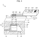
- FIG. 1 is a schematic diagram showing a schematic configuration of a medical device according to an exemplary embodiment 1.
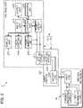
- FIG. 2 is a block diagram showing a functional configuration of the medical device according to the exemplary embodiment 1.
- the medical device 1 shown in FIGS. 1 and 2 includes an implantable medical instrument 10 for use in a living body 100 of a subject, and an extracorporeal unit 20 that detects a predetermined location in the medical instrument 10.
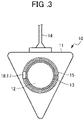
- FIG. 3 is a schematic diagram showing a schematic configuration of the medical instrument 10.
- the medical instrument 10 shown in FIGS. 1 , 2 and 3 is, for example, referred to as a subcutaneous implantable port (CV port). As shown in FIGS. 1 , 2 , and 3 , a body portion 11 of the medical instrument 10 is used by implanting in the living body 100.
- CV port subcutaneous implantable port
- the body portion 11 is, for example, a housing made of epoxy resin or other materials. As shown in FIGS. 1 , 2 , and 3 , the body portion 11 includes a medicinal solution container 12, a soft portion 13, a catheter 14, a first coil 15, a power receiving circuit 16, and a first communication unit 17.
- the medicinal solution container 12 is a chamber for temporarily storing a medicinal solution.
- the medicinal solution container 12 has an opening 12a having a circular or substantially circular shape on the outside of the body portion 11.
- the soft portion 13 is referred to as a septum.
- the soft portion 13 closes the opening 12a of the medicinal solution container 12.
- the soft portion 13 is, for example, a soft lid body (silicone diaphragm) made of silicone rubber, and is exposed from the body portion 11 as well. Furthermore, the soft portion 13 has a columnar or substantially columnar shape.
- the soft portion 13 is a portion through which an injection needle for the injection (infusion) of a medicinal solution can be inserted from a body surface 101 of a subject after the body portion 11 is implanted within the living body 100.
- the catheter 14 has one end in communication with the medicinal solution container 12, and the other end for insertion into a blood vessel or the like (not shown). This catheter 14 transports the medicinal solution temporarily stored in the medicinal solution container 12.
- the first coil 15 winds a plurality of times in an annular shape on the end surface of the outside of the body portion of the medicinal solution container 12, and thus provided around the soft portion 13.
- the first coil 15 is small, and mainly constituted by copper wire in order to increase the feeding power; however, for weight reduction, the first coil 15 may be constituted by aluminum wire.
- the first coil 15 has a weight of about 5 g.
- the first coil 15 is formed by molding in a manner that is integral with the body portion 11.
- the power receiving circuit 16 receives the power generated in the first coil 15 (induced electromotive force), and outputs the received power result of the power to the first communication unit 17. It should be noted that, in the exemplary embodiment 1, the first coil 15 and the power receiving circuit 16 serve as a power receiving unit.
- the first communication unit 17 receives the received power result inputted from the power reception circuit 16 via the first coil 15, and transmits a radio wave to the extracorporeal unit 20.
- the power receiving circuit 16 and the first communication unit 17 may be integrally formed in the IC chip, or may be separately formed. It should be noted that, when a subject implanted with the medical instrument 10 uses MRI, the IC chip may be exposed to a strong magnetic field. Therefore, the medical instrument 10 may include a current detecting function for detecting a current flowing through the first coil 15, and a cut-off function such as a switch for electrically shutting off among the first coil, the power receiving circuit 16, and the first communication unit 17.
- the IC chip when a large current equal to or greater than a predetermined threshold is detected by the current detection function, it is possible for the IC chip to cut off the current flowing through the first communication unit 17 by electrically cutting off the first coil, the power receiving circuit 16, and the first communication unit 17 by the cut-off function.
- FIG. 4 is a schematic diagram showing a schematic configuration of the extracorporeal unit 20.
- the extracorporeal unit 20 shown in FIGS. 1 , 2 , and 4 detects a predetermined location in the implantable medical instrument 10 for use in the living body 100.
- the extracorporeal unit 20 detects that the relative positional relationship between the first coil 15 of the medical instrument 10 and a power transmission unit 22, which will be described later, has reached a predetermined state.
- the extracorporeal unit 20 includes a housing unit 21 and a power transmission unit 22 attachable and detachable to the housing unit 21. It should be noted that the housing unit 21 and the power transmission unit 22 may be integrally formed. Although details will be described later, as shown in FIG. 1 , it is preferable that the inner diameter dimension R2 of a hole 224 is smaller than the outer diameter dimension R1 of the soft portion 13.
- the housing unit 21 houses a circuit board on which, for example, a power supply and IC chips to be described later are mounted.
- the housing unit 21 supplies power to the power transmission unit 22, and receives the received power result received by the power transmission unit 22.
- the housing unit 21 includes a first connecting portion 211, a power supply unit 212, a second communication unit 213, an input unit 214, a recording unit 215, an output unit 216, a display unit 217, a light emitting unit 218, and a control unit 219.
- the first connecting portion 211 is electrically connectable to the power transmission unit 22 mounted on the housing unit 21, and supplies power inputted from the power supply unit 212 to the power transmission unit 22.
- the first connecting portion 211 includes, for example, a female electrical coupler.
- the power supply unit 212 supplies power to the power transmission unit 22 via the first connecting portion 211 under the control of the control unit 219.
- the power supply unit 212 includes a battery, a booster circuit, and other components.
- the second communication unit 213 outputs the received power result (signal) received by the power transmission unit 22 via the first connecting portion 211 to the control unit 219 under the control of the control unit 219.
- the input unit 214 receives an input of an operation by the user.
- the input unit 214 is implemented by using buttons, switches, a touch panel, and other components.
- the user refers to any one of a medical doctor, a nurse, a caregiver, and a patient himself/herself as a subject.
- the recording unit 215 records various programs and information executed by the extracorporeal unit 20.
- the recording unit 215 is implemented using volatile memory and nonvolatile memory.
- the output unit 216 outputs sound under the control of the control unit 219.
- the output unit 216 is implemented by using, for example, a speaker or other components.
- the display unit 217 displays predetermined information under the control of the control unit 219.
- the display unit 217 is implemented by using, for example, a liquid crystal or an organic EL (Electro Luminescence).
- the light emitting unit 218 emits light under the control of the control unit 219.
- the light emitting unit 218 is implemented by using LEDs (Light Emitting Diode).
- the control unit 219 controls each unit and each portion constituting the extracorporeal unit 20.
- the control unit 219 controls the power supply unit 212 to supply power to the power transmission unit 22 via the first connecting portion 211.
- the control unit 219 causes the light emitting unit 218 to emit light so as to notify that the relative positional relationship between the power transmission unit 22 and the medical instrument 10 has reached a predetermined state.
- control unit 219 causes the light emitting unit 218 to emit light so as to notify that the relative positional relationship with the medical instrument 10 has reached a predetermined state, for example, a state in which a second coil 222 of the power transmission unit 22 to be described later is located on the first coil 15 of the medical instrument 10, based on the power of the received power result from the second communication unit 213.
- the control unit 219 is implemented by using memory and a processor having hardware such as a CPU (Central Processing Unit).
- the user presses the input unit 214 of the extracorporeal unit 20 so as to supply power from the power supply unit 212 of the housing unit 21 to the second coil 222 of the power transmission unit 22. Then, the user brings the power transmission unit 22 of the extracorporeal unit 20 closer to the medical instrument 10 while searching for the medical instrument 10 embedded in the living body 100. In this case, power is supplied from the power supply unit 212 via a second connecting portion 223 and the first connecting portion 211, whereby the second coil 222 generates a magnetic flux.
- the light emitting unit 218 notifies the user by emitting light indicating that the relative positional relationship between the first coil 15 of the medical instrument 10 and the second coil 222 has reached a predetermined position in the medical instrument 10.
- the medical device 1 notifies the user by emitting light.
- the user it is possible for the user to easily confirm the position of the soft portion 13 in the implantable medical instrument 10 for use in the living body 100. More specifically, it is possible for the user to recognize that the soft portion 13 is located below the hole 224 at the position where the light emitting unit 218 emits light.
- the control unit 219 may notify the user by not only causing the light emitting unit 218 to emit light, but also causing the output unit 216 to output sound. Furthermore, the control unit 219 may notify the user by causing the display unit 217 to display information indicating that the second coil 222 has reached the soft portion 13 of the medical instrument 10.
- the user inserts the injection needle through the hole 224 provided inside the power transmission unit 22 at a mark provided thereon.
- the user inserts the injection needle through the hole 224 provided inside the power transmission unit 22 at a mark provided thereon.
- the fact that the relative positional relationship between the first coil 15 of the medical instrument 10 and the second coil 222 have reached the predetermined position is notified by causing the light emitting unit 218 to emit light, such that it is possible to easily confirm the position of the soft portion 13 in the implantable medical instrument 10 for use in the living body 100.
- the housing unit 21 can be used for other subjects, such that the cost of introducing the medical device 1 can be reduced.
- the position (shape) of the soft portion 13 in the medical instrument 10 can be easily confirmed by the light emitting unit 218 emitting light for the notification.
- the hole 224 is provided at the center where the second coil 222 of the power transmission unit 22 is provided, it is possible to easily insert the injection needle into the soft portion 13 of the medical instrument 10 in a state in which the relative positional relationship between the first coil 15 of the medical instrument 10 and the second coil 222 have reached a predetermined position.
- exemplary embodiment 2 will be described.
- the fact that the relative positional relationship between the first coil 15 in the medical instrument 10 and the second coil 222 has reached a predetermined state is notified by the light emitting unit 218 of the extracorporeal unit 20 performing light emission or the like.
- a notification unit is provided in a medical instrument to perform a notification.
- the same components as those of the medical device 1 according to exemplary embodiment 1 described above are denoted by the same reference numerals, and a detailed description thereof is omitted.
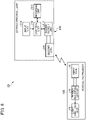
- FIG. 5 is a schematic diagram showing a schematic configuration of a medical instrument according to exemplary embodiment 2.
- FIG. 6 is a block diagram showing a functional configuration of the medical device according to exemplary embodiment 2.
- a medical device 1D shown in FIGS. 5 and 6 includes an implantable medical instrument 10D for use in the living body 100 of a subject, and an extracorporeal unit 20D that detects a predetermined location in the medical instrument 10.
- FIG. 7 is a schematic diagram showing a schematic configuration of the medical instrument 10D.
- the medical instrument 10D shown in FIGS. 5 , 6 , and 7 includes a plurality of light emitting units 60 in addition to the configuration of exemplary embodiment 1 described above, and the first communication unit 17 is omitted.
- the light emitting units 60 are arranged in an annular or substantially annular shape at predetermined intervals around the soft portion 13. More specifically, the light emitting units 60 are disposed at three positions around the soft portion 13 in an annular or substantially annular shape every 120 degrees in the middle of the first coil 15.
- the light emitting units 60 each emit light according to the power received by the power receiving circuit 16D.
- the light emitting units 60 each include an LED. More specifically, it is preferable for the light emitting unit 60 to use an LED having high directivity. More specifically, it is preferable that the light emitting units 60 each use a red LED that emits light in a red wavelength band when transmitting through a living body such as a subject. As shown in FIG. 8 , the number and arrangement of the light emitting units 60 can be changed as appropriate.
- the extracorporeal unit 20D shown in FIGS. 5 and 6 , the second communication unit 213, the output unit 216, the display unit 217, and the light emitting unit 218 are omitted from the configuration of the housing unit 21 of exemplary embodiment 1 described above. Furthermore, the extracorporeal unit 20D further includes a second coil 230.
- the second coil 230 has an annular or substantially annular shape, generates a magnetic flux in response to the power inputted from the power supply unit 212, and transmits power to the first coil. Furthermore, the power supplied by the second coil 230 allows the light emitting unit 60 to emit light when a predetermined distance between the second coil 230 and the first coil 15 is provided, for example, even when a distance of about several tens of cm is provided therebetween.
- the medical device 1D configured as described above supplies electric power from the extracorporeal unit 20D, and the plurality of light emitting units 60 in the medical instrument 10D emit light, thereby notifying the location where the medical instrument 10D is implanted.
- the user it is possible for the user to intuitively grasp the position and the center of the soft portion 13 in the medical instrument 10D from the outside of the subject.
- the position of the soft portion 13 in the medical instrument 10D can be intuitively grasped from the outside of the subject.
- the notification is performed by providing a notification unit in the medical instrument.
- the first coil 15 is disposed around the soft portion 13; however, in the medical instrument 10G according to exemplary embodiment 3, a first coil 15 is disposed for one light emitting unit 60, or first coils 15 are provided for respective light emitting units 60.
- the same components as those of the medical device 1 according to exemplary embodiment 1 and the medical instrument 10D according to exemplary embodiment 2 described above are denoted by the same reference numerals, and detailed descriptions thereof are omitted.
- FIG. 9 is a schematic diagram showing a schematic configuration of a medical device according to exemplary embodiment 3.
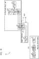
- FIG. 10 is a block diagram showing the functional configuration of the medical device according to exemplary embodiment 3.
- a medical device 1G shown in FIGS. 9 and 10 includes an implantable medical instrument 10G for use in a living body 100 of a subject, and an extracorporeal unit 20G that detects a predetermined location in the medical instrument 10G.
- the light emitting units 60 include the light emitting units 60a, 60b, and 60c, this is not limitative. Details thereof will be described later.
- the first coil 15 includes the first coils 15a, 15b, and 15c; however, this is not limitative.
- the extracorporeal unit 20G includes a housing unit 21, and a power transmission unit 22 which is attachable to and detachable from the housing unit 21.
- the concept of "power transmission unit” encompasses a "power transmission sheet”.
- the housing unit 21 and the power transmission unit 22 are connected to each other in a wired or wireless manner. In a case of a wired manner, it is considered that they are connected by a cable of a predetermined length to supply power from the housing unit 21 to the power transmission unit 22. Furthermore, in a case of a wireless manner, it is considered that a non-contact power supply is used to supply power from the housing unit 21 to the power transmission unit 22, for example.
- FIG. 11 is a block diagram showing a functional configuration of the medical instrument 10G.
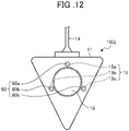
- FIG. 12 is a schematic diagram showing a schematic configuration of the medical instrument 10G.
- the medical device 1G includes the power transmission unit 22, the power receiving unit, and the medical instrument 10G.
- the power transmission unit 22 includes the second coil 222 that transmits power in a non-contact manner.
- the power receiving unit includes the first coil 15 and the power receiving circuit 16.
- the first coil 15 receives power transmitted from the power transmission unit 22.
- the power receiving circuit 16 transmits the power received by the first coil 15 (induced electromotive force) to the notification unit.
- the notification unit is implemented by, for example, the light emitting unit 60, which will be described later.
- the power receiving circuit 16 converts the power received by the first coil 15 to a predetermined power, and transmits the converted power to the notification unit.
- the medical instrument 10G includes the power receiving unit, and is implanted in a body. More specifically, the medical instrument 10G includes the notification unit and the soft portion 13.
- the notification unit includes a plurality of light emitting units 60 which notify that the relative positional relationship between the power transmission unit 22 and the power receiving unit has reached a predetermined state along with the movement of the power transmission unit 22, by emitting light using the power received by the power receiving unit.
- the plurality of light emitting units 60 are arranged along the outer edge of the soft portion 13. For example, the plurality of light emitting units 60 are arranged at predetermined intervals along the outer edge of the soft portion 13. An injection needle for injecting a medicinal solution is used for insertion into the soft portion 13.
- three light emitting units 60 are arranged at predetermined intervals (e.g., every 120 degrees) around the soft portion 13; however, the number of light emitting units 60 may be two or may be four or more.
- the power receiving unit includes a plurality of power receiving units.
- the plurality of light emitting units 60 each emit light using the power received by the power receiving unit connected thereto.
- FIG. 11 shows a configuration example including three sets each including a light emitting unit 60, a first coil 15, and a power receiving circuit 16.
- FIG. 12 is a diagram showing a schematic appearance of the medical instrument 10G.
- the medical instrument 10G includes first coils 15a, 15b, and 15c, power receiving circuits 16a, 16b, and 16c, and light emitting units 60a, 60b, and 60c.
- first coil 15 may refer to one among the individual first coils 15a, 15b, and 15c, or alternatively may refer to a concept collectively referring to the first coils 15a, 15b, and 15c.
- power receiving circuit 16 may refer to one among the individual power receiving circuits 16a, 16b, and 16c, or alternatively may refer to a concept collectively referring to the power receiving circuits 16a, 16b, and 16c.
- the "light emitting unit 60” may refer to one among the individual light emitting units 60a, 60b, and 60c, or alternatively may refer to a concept collectively referring to the light emitting units 60a, 60b, and 60c.
- the first coil 15a supplies the received power to the light emitting unit 60a via the power receiving circuit 16a.
- the first coil 15b supplies the received power to the light emitting unit 60b via the power receiving circuit 16b.
- the first coil 15c supplies the received power to the light emitting unit 60c via the power receiving circuit 16c.
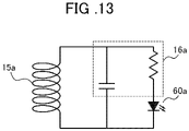
- FIG. 13 shows a circuit diagram of the power receiving unit. It should be noted that FIG. 13 shows a configuration of a set including the light emitting unit 60a, the first coil 15a, and the power receiving circuit 16a.
- the light emitting units 60a, 60b, and 60c can emit light independently of each other, and the power receiving unit can be manufactured without depending on the size or shape of the outer diameter of the soft portion 13.
- FIG. 14 is a diagram showing a specific configuration of the power receiving unit.
- the first coil 15a for transmitting power to the light emitting unit 60a may be wound on the cylindrical iron core F with a small diameter. Since the power receiving unit is integrated in this manner, it can be disposed at any position outside of the medicinal solution container 12. Furthermore, since the power receiving unit includes a configuration in which one coil is provided in one light emitting unit, it is possible to further increase the received power by increasing the number of turns of the coil within the range that can be accommodated in the body outer shape, and it is possible to improve the light emission, leading to enhanced visual recognition. Furthermore, it is preferable that the cylindrical coil has a diameter of 2 mm or less and a height of 5 mm or less.
- a plurality of light emitting units 60 share the power receiving unit, and emit light using the power received by the power receiving unit.
- FIG. 15 is a diagram showing a configuration in which the power receiving unit includes one first coil 15, three light emitting units 60a, 60b, and 60c, and three power receiving circuit 16a, 16b, and 16c.
- FIG. 16 is a diagram showing a schematic appearance of the medical instrument 10G.
- FIG. 17 is a circuit diagram in a case in which the power receiving unit includes one first coil 15, three light emitting units 60a, 60b, and 60c, and three power receiving circuits 16a, 16b, and 16c.
- the medical instrument 10G includes the first coil 15, the power receiving circuits 16a, 16b, and 16c, and the light emitting units 60a, 60b, and 60c.
- the power receiving circuit 16 may include a single capacitor, and may be shared by the light emitting unit 60a, 60b, and 60c.
- the power receiving circuit 16a, 16b, and 16c, and the light emitting unit 60a, 60b, and 60c may share the first coil 15.
- FIG. 17 shows a circuit diagram in a case in which the power receiving unit includes the first coil 15 and three light emitting units 60.
- a pair of the power receiving circuit 16a and the light emitting unit 60a, a pair of the power receiving circuit 16b and the light emitting unit 60b, and a pair of the power receiving circuit 16c and the light emitting unit 60c, are connected to the first coil 15 in parallel.
- the light emitting units 60a, 60b, and 60c can emit light at the same time, and the power receiving unit can be manufactured without depending on the size or shape of the outer diameter of the soft portion 13.
- FIG. 16 shows a configuration in which the first coil 15 is installed in an annular or substantially annular shape only around the light emitting unit 60a; however, the present invention is not limited to this configuration, and may be installed in an annular or substantially annular shape around the soft portion 13 as shown in FIG. 7 .
- the notification unit includes a first light intensity in the brightest location in a circle having a first radius smaller than the inner diameter of the soft portion 13, and a second light intensity in the brightest location outside the circle having a second radius larger than the first radius, and the first and second light intensities differ from each other.
- FIG. 18 is a diagram for explaining a case in which the first light intensity and the second light intensity have a first relationship.
- the first relationship refers to "first light intensity” > "second light intensity”.
- r11 represents the inner diameter of the soft portion 13.
- r12 represents a first radius smaller than the inner diameter of the soft portion 13.
- r13 represents a second radius larger than the first radius.
- c11 represents an inner circle having the first radius r12.
- c12 represents an outer circle having a second radius r13.
- the brightest location in the inner circle c11 having the first radius r12 refers to, for example, the vicinity of the center of the inner circle c11.
- the brightest location in the outer circle c12 having the second radius r13 refers to, for example, the vicinity of the circumference of the outer circle c12.
- the notification unit can emit light differently to show the difference between the first light intensity and the second light intensity, whereby it is possible to notify the location near the center of the soft portion 13.
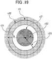
- FIG. 19 is a diagram for explaining a case in which the first light intensity and the second light intensity have a second relationship.
- the second relationship refers to "first light intensity" ⁇ "second light intensity”.
- r21 represents the inner diameter of the soft portion 13.
- r22 represents a first radius smaller than the inner diameter of the soft portion 13.
- r23 represents a second radius larger than the first radius.
- c21 represents an inner circle having the first radius r22.
- c22 represents an outer circle having the second radius r23.
- the brightest location in the inner circle c21 having the first radius r22 refers to, for example, the vicinity of the center of the inner circle c21.
- the brightest location in the outer circle c22 having the second radius r23 refers to, for example, the vicinity of the circumference of the outer circle c22.
- the notification unit is configured so that the first light intensity and the second light intensity differ from each other, such that it is possible for the notification unit to notify the location in the vicinity of the center of the soft portion 13.
- the light emitted from the light emitting unit 60 diffuses, when the light passes through the skin surface from the inside of the body, the transmitted light may be blurred, and the position of the soft portion 13 may become difficult to visually recognize. Therefore, it is preferable to suppress the diffusion of the light.
- a light emitting unit in a cylindrical member having a reflective inner surface, the diffusion of light is suppressed, transmitted light is not blurred, and the position of the soft portion 13 (center position) is more easily visually recognized.
- the light emitting unit 60 since the light emitting unit 60 has a certain emission angle, the light is diffused. However, when the installation angle of the light emitting unit 60 disposed around the soft portion 13 is sloped outward from the direction perpendicular or substantially perpendicular to the emission surface of the light, the vicinity of the center of the soft portion 13 becomes darker than the periphery of the soft portion 13. This makes it easier to visually recognize the center of the soft portion 13.
- the extracorporeal unit 20 which is an external power supply device, has a function of adjusting the amount of electric power.
- the extracorporeal unit 60 which is an external power supply device, has a function of adjusting the amount of electric power.
- the amount of light emitted from the light emitting unit 60 so as to reduce the amount of electric power to the extent that the center of the soft portion 13 can be visually recognized.
- FIG. 20 is a diagram for explaining a first example in which the notification unit is configured such that the first light intensity and the second light intensity have a first relationship.
- FIG. 20 is a diagram schematically showing a state when the soft portion 13 is viewed from the top surface. Furthermore, FIG. 20 schematically shows a state in which the light emitting units 60a, 60b, and 60c constituting the notification unit emit light.
- FIG. 21 is a diagram schematically showing a state in which the light emitting unit 60a is sloped toward the center of the soft portion 13. It should be noted that, although only the light emitting unit 60a is shown in FIG. 21 , the light emitting units 60b and 60c are also sloped toward the center of the soft portion 13. In this manner, the light emitting units 60a, 60b, and 60c are disposed so as to be sloped at a predetermined angle toward the center of the soft portion 13.
- the notification unit to emit light differently between the first light intensity and the second light intensity such that the vicinity of the center of the soft portion 13 is brighter than the outer periphery, and thus it is possible to notify the position of the vicinity of the center of the soft portion 13.
- the light emitting units 60a, 60b, and 60c may emit light in different colors from each other. More specifically, for example, when the light emitted by the light emitting unit 60a is red (R), the light emitted by the light emitting unit 60b is green (G), and the light emitted by the light emitting unit 60c is blue (B), the vicinity of the center of the soft portion 13 in which each color is mixed (subtractive color mixing) is white. Therefore, it is possible to set the color (white) near the center of the soft portion 13 to be different from the color at locations other than the location near the center of the soft portion 13. The difference in colors makes it possible to notify the location in the vicinity of the soft portion 13.
- FIG. 22 is a diagram schematically showing a state in which the light emitting unit 60a is viewed from the lateral side. It should be noted that, although only the light emitting unit 60a is shown in FIG. 22 , the light emitting units 60b and 60c have similar configurations.
- members 61 for preventing the diffusion of light and guiding the optical path to the center of the soft portion 13 may be provided around the light emitting unit 60. Even with such a configuration, the optical paths of the light emitting units 60a, 60b, and 60c can be concentrated at the center of the soft portion 13.
- Each of the members 61 may have, for example, a cylindrical shape.
- the member 61 may include a reflective member such as aluminum on the inner side thereof so as to reflect the light from the light emitting unit 60.
- the member 61 may include, for example, a lens for condensing the light emitted from the light emitting unit 60. It should be noted that the shape and structure of the member 61 are not limited to the above-described examples, and may vary.
- the notification unit can emit light differently between the first light intensity and the second light intensity, and thus possible to notify the location in the vicinity of the center of the soft portion 13.
- FIG. 23 is a diagram for explaining a second example in which the notification unit is configured so that the first light intensity and the second light intensity have a first relationship.
- FIG. 23 is a schematic view of the soft portion 13 when viewed from the upper surface.
- FIG. 23 schematically shows a state in which the light emitting units 60a, 60b, and 60c constituting the notification unit emit light.
- FIG. 24 is a diagram schematically showing a state in which the light emitting unit 60a is sloped toward the outside of the soft portion 13. It should be noted that, although only the light emitting unit 60a is shown in FIG. 24 , the light emitting units 60b and 60c are also sloped toward the outside of the soft portion 13. In this manner, the light emitting units 60a, 60b, and 60c are disposed so as to be sloped at a predetermined angle toward the outside of the soft portion 13.
- the notification unit can notify the location in the vicinity of the center of the soft portion 13.
- FIG. 25 is a diagram schematically showing a state when the light emitting unit 60 is viewed from the lateral side.
- members 62 for preventing the diffusion of light and guiding the optical path to the periphery of the soft portion 13 may be provided around the light emitting unit 60. Even with such a configuration, the optical paths of the light emitting units 60a, 60b, and 60c can be concentrated at the periphery of the soft portion 13.
- Each of the members 62 may have, for example, a cylindrical shape.
- the member 62 may include a reflective member such as aluminum on the inner side thereof so as to reflect the light from the light emitting unit 60.
- the member 62 may include, for example, a lens for condensing the light emitted from the light emitting unit 60. It should be noted that the shape and structure of the member 62 are not limited to the above-described examples, and may vary.
- the notification unit can emit light differently between the first light intensity and the second light intensity, and thus the notification unit can notify the location in the vicinity of the center of the soft portion 13.
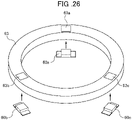
- FIG. 26 is a diagram schematically showing a member 63 in which cylindrical holes 63a, 63b, and 63c for attaching (embedding) the light emitting unit 60 are provided.
- the member 63 has an annular or substantially annular shape, and has a hole having a predetermined size provided at the center thereof.
- the member 63 is disposed on the body portion 11 so that the surface of the soft portion 13 is exposed from the hole.
- the cylindrical holes 63a, 63b, and 63c are disposed uniformly around the member 63 (for example, at 120 degrees).
- the light emitting unit 60a is attached to the cylindrical hole 63a.
- the light emitting unit 60b is attached to the cylindrical hole 63b.
- the light emitting unit 60c is attached to the cylindrical hole 63c.
- the cylindrical holes 63a, 63b, 63c are sloped to the center side or the circumferential side of the member 63.
- the cylindrical holes 63a, 63b, and 63c are provided to tilt the optical path of each light emitting unit 60 in the direction that guides the optical path to the center of the soft portion 13 (toward the center of the member 63), the same effect as that obtained when the member 61 is provided can be obtained.
- the cylindrical holes 63a, 63b, and 63c are provided in a direction that guides the optical path of each light emitting unit 60 to the periphery of the soft portion 13 (on the circumferential side of the member 63), the same effect as that obtained when the member 62 is provided can be obtained.
- cylindrical holes 63a, 63b, and 63c are uniformly provided on the circumference of the member 63, the positioning of the light emitting units 60a, 60b, and 60c can be easily performed, and the same effect as when the member 61 or 62 is provided can be achieved simply by attaching the light emitting units 60a, 60b, and 60c to the cylindrical holes 63a, 63b, and 63c, respectively.
- FIG. 27 is a schematic diagram showing a schematic configuration of the power transmission unit 22.
- the power transmission unit 22 has a function of transmitting power in a non-contact manner.
- the power transmission unit 22 shown in FIG. 1 , FIGS. 2 , and FIG. 27 has a plate-shaped sheet portion 221.
- the sheet portion 221 includes the second coil 222 on one side thereof for transmitting electric power, and has a hole 224 in the second coil 222 for insertion of an injection needle thereinto.
- the sheet portion 221 includes the second connecting portion 223 on the other side thereof.
- the second connecting portion 223 electrically connects the second coil 222 and the power supply unit 212 of the housing unit 21 with each other. It should be noted that it is necessary to prevent the injection needle from shifting from the soft portion 13 when the injection needle is pierced. As will be described later in detail, it is preferable that the hole 224 is slightly smaller than the soft portion 13.
- the sheet portion 221 has an arc shape on both ends in the longitudinal direction.
- the sheet portion 221 is implemented using, for example, a nonwoven fabric or the like.
- the sheet portion 221 includes two sheets of nonwoven fabric sandwiching the second coil 222 and the second connecting portion 223.
- a seal member provided with an attachment member, an adhesive member, or the like, which can be attached to a subject, may be provided on the back side (subject side) of the sheet portion 221.
- a lubricant, in place of the seal member may be applied to the back side (the subject side) of the sheet portion 221 so as to be able to smoothly move on the body surface 101 of the subject.
- the second coil 222 has an annular or substantially annular shape, and is provided on one side of the sheet portion 221 in the longitudinal direction.
- the second coil 222 generates a magnetic flux in response to the power inputted from the housing unit 21 via the second connecting portion 223.
- the second connecting portion 223 is provided on the other side of the sheet portion 221 in the longitudinal direction, and electrically connects the power supply unit 212 of the housing unit 21 and the second coil 222.
- the second connecting portion 223 includes, for example, a male electrical coupler.
- the hole 224 is provided in the second coil 222.
- the hole 224 is provided at the center of the second coil 222.
- the hole 224 allows for the insertion and removal of the injection needle. It should be noted that the inner diameter of the second coil 222 and the diameter of the hole 224 can be appropriately changed in accordance with the diameter of the soft portion 13.
- the hole 224 is slightly larger than the diameter of the injection needle. It is preferable that the diameter of the hole 224 is equal to or less than the diameter of the injection needle + 0.2 mm.
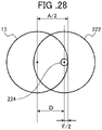
- the size (diameter F) of the hole 224 will be described below; however, the diameter F of the hole 224 is considered in various ways, and thus is not limited to the following description.
- FIG. 28 is a diagram for explaining the diameter F of the hole 224.
- the size of the soft portion 13 and the size of the second coil 222 are substantially the same.
- A indicates the diameter of the soft portion 13.
- D indicates the distance between the center of the soft portion 13 and the center of the second coil 222 when the light emitting unit 60 can emit light. That is, the distance D shows the amount of deviation (accuracy) between the center of the second coil 222 and the center of the soft portion 13.
- the diameter F of the hole 224 is determined depending on the tolerable amount of deviation.
- the distance D can be controlled by controlling the magnitude of the magnetic flux generated from the extracorporeal unit 20G.
- the notification unit operates (emits light) by the power received by the first coil 15 even when the distance between the second coil 222 and the first coil 15 is a predetermined distance or more.
- the notification by the notification unit since the notification by the notification unit can be performed at a location where the center of the second coil 222 and the center of the soft portion 13 are separated from each other, it is necessary for the diameter F of the hole 224 to be smaller than that of the second configuration to be described later.
- FIGS. 29 , 30 , and 31 are diagrams for explaining the relationship between the hole 224 and the soft portion 13 in the case of the first configuration.
- the inner diameter of the hole 224 is substantially the same as or slightly larger than the outer diameter of the injection needle 40 based on the expression (1), even when the center of the second coil 222 is deviated from the center of the soft portion 13, the injection needle 40 still can hit the soft portion 13 when the injection needle 40 is inserted into the hole 224. Furthermore, as shown in FIGS.
- the notification unit when the magnetic flux generated from the extracorporeal unit 20 is small (hereinafter, referred to as a second configuration), and when the distance between the second coil 222 and the first coil 15 is within the predetermined distance, the notification unit operates (emits light) by the power received by the first coil 15.
- the notification since the notification is performed by the notification unit at a location where the center of the second coil 222 and the center of the soft portion 13 are close to each other, it is possible to make the diameter F of the hole 224 larger than that of the first configuration described above.
- the input unit 214 inputs a value based on a user operation to the control unit 219.
- the control unit 219 controls the power supply unit 212 based on the value inputted from the input unit 214.
- the power supply unit 212 supplies power to the second coil 222 based on the control of the control unit 219.
- the user when it is desired to generate a large magnetic flux from the extracorporeal unit 20, the user inputs the value V1 to the control unit 219 using the input unit 214.
- the user when it is desired to generate a small magnetic flux from the extracorporeal unit 20, the user inputs the value V2 to the control unit 219 using the input unit 214.
- the relationship of value V1 > value V2 is satisfied.
- a medical doctor or a nurse as a user can puncture the soft portion 13 with an injection needle so as not to deviate from the soft portion 13.
- the distance D is obtained from the expression (2) as follows.
- the diameter F of the hole 224 is determined as the diameter of the injection needle.
- the diameter F of the hole 224 (the diameter of the injection needle) is determined to have the upper limit of SUS304, nominal 19G (outer diameter (mm) : 1.08 ⁇ 0.02).
- D ⁇ 8.0 ⁇ 1.1 / 2 3.45 mm
- the notification unit In the case of determining the distance D large, it is possible for the notification unit to notify the position of the soft portion 13 even when the center of the second coil 222 and the center of the soft portion 13 (strictly, the first coil 15) are separated. In this manner, when the distance D is determined to be large, it is possible for a medical doctor or a nurse as a user to know the position of the soft portion 13 by a simple procedure.
- the notification unit when the distance D is determined to be small, it is possible for the notification unit to notify the position of the soft portion 13 by bringing the center of the second coil 222 to some extent close to the center of the soft portion 13 (strictly, the first coil 15).
- the diameter F of the hole 224 it is possible for the diameter F of the hole 224 to be larger as compared with the case where the distance D is determined to be small, such that a medical doctor or a nurse as a user can select a location where the injection needle is to be inserted, and thus it is possible to prevent the same location of the soft portion 13 from being punctured many times with the injection needle, whereby the life of the soft portion 13 can be extended.
- the hole 224 may have a diameter as large as or larger than the diameter of the injection needle in order to pass through the injection needle. It should be noted that, when the injection needle is designed to penetrate the sheet portion 221, it is not necessary to provide the hole 224 in the sheet portion 221. In such a configuration, it will suffice if a mark indicating a location for the puncture of the injection needle is provided on the sheet portion 221 (for example, a location corresponding to the center of the second coil 222).
- the diameter F of the hole 224 is not limited to the expressions (2), (4), and (5) .
Landscapes
- Health & Medical Sciences (AREA)
- Engineering & Computer Science (AREA)
- Life Sciences & Earth Sciences (AREA)
- Heart & Thoracic Surgery (AREA)
- General Health & Medical Sciences (AREA)
- Veterinary Medicine (AREA)
- Biomedical Technology (AREA)
- Public Health (AREA)
- Animal Behavior & Ethology (AREA)
- Power Engineering (AREA)
- Hematology (AREA)
- Anesthesiology (AREA)
- Pulmonology (AREA)
- Computer Networks & Wireless Communication (AREA)
- Physics & Mathematics (AREA)
- Biophysics (AREA)
- Radiology & Medical Imaging (AREA)
- Nuclear Medicine, Radiotherapy & Molecular Imaging (AREA)
- Medical Informatics (AREA)
- Molecular Biology (AREA)
- Surgery (AREA)
- Pathology (AREA)
- Human Computer Interaction (AREA)
- Vascular Medicine (AREA)
- Electromagnetism (AREA)
- Acoustics & Sound (AREA)
- Gastroenterology & Hepatology (AREA)
- External Artificial Organs (AREA)
- Infusion, Injection, And Reservoir Apparatuses (AREA)
- Endoscopes (AREA)
- Media Introduction/Drainage Providing Device (AREA)
Abstract
Description
- The present disclosure relates to a medical device for detecting a position of an implantable medical instrument for use within the body of a subject, an extracorporeal unit, a power transmission sheet, and the medical instrument.
- A body-implantable medical device in which a body portion of a medical instrument is implanted into a body is used for charging a medicinal solution into the body. This medical instrument reduces the burden on patients who need frequent injections for charging a medicinal solution. Such a medical instrument has a soft portion through which an injection needle is inserted into the body portion. This soft portion is made of, for example, silicone rubber or other materials. With the medical instrument, a medicinal solution is injected into a medicinal solution container through the soft portion. The medicinal solution is transported through a catheter to blood vessels.
- In such a medical instrument, since the body portion is implanted in the body, it is difficult to specify the position of the soft portion by way of visual recognition from the outside of the body.
- Therefore, a medical instrument is considered which includes a soft portion provided by mixing a luminescent material that emits near-infrared fluorescence by irradiation with near-infrared excitation light with a resin material, by applying the technique proposed in
Patent Document 1. In such a medical instrument, there is a possibility of the position of the soft portion being able to be visually specified by converting the near-infrared fluorescence into visible light. - Patent Document 1:
Japanese Patent No. 5958922 - However, when such a luminescent material is mixed with the resin material to constitute a soft portion, there is a possibility of the luminescent material is aggregating and the amount of near-infrared fluorescence emitted by the luminescent material being reduced due to concentration quenching, such that it is difficult to specify the position of the soft portion as a result.
- It should be noted that, although a medical instrument having a soft portion has been described here, a similar problem has also occurred in an intracorporeal implantable medical device without a soft portion.
- Exemplary embodiments of the present disclosure provide a medical device that makes it possible to easily confirm a predetermined location in an implantable medical instrument for use in a body, an extracorporeal unit, a power transmission sheet, and the medical instrument.
- An exemplary embodiment of the present invention provides a medical device including: a power transmission unit including a second coil that transmits power in a non-contact manner; a power receiving unit including a first coil that receives the power transmitted from the power transmission unit; and an implantable medical instrument for use in a body, the implantable medical instrument including the power receiving unit, the implantable medical instrument including: a notification unit including a plurality of light emitting units which notify that a relative positional relationship between the power transmission unit and the power receiving unit has reached a predetermined state along with a movement of the power transmission unit, by emitting light using the power received by the power receiving unit; and a soft portion for insertion of an injection needle, in which the plurality of light emitting units is arranged along an outer edge of the soft portion.
- Furthermore, in the above medical device, the power receiving unit includes a plurality of power receiving units, and the plurality of light emitting units each emit light using power received by a corresponding one of the plurality of power receiving units connected thereto.
- Furthermore, in the above medical device, the plurality of light emitting units share the power receiving unit, and emit light using the power received by the power receiving unit.
- Furthermore, in the above medical device, the notification unit includes a first light intensity in a brightest location in a circle having a first radius smaller than an inner diameter of the soft portion, and a second light intensity in a brightest location outside a circle having a second radius larger than the first radius, in which the first light intensity and second light intensity differ from each other.
- Furthermore, in the above medical device, the power transmission unit includes a plate-shaped sheet portion, the plate-shaped sheet portion includes a second coil that transmits the power, and has a hole in the second coil for insertion of an injection needle thereinto, and a diameter F of the hole is defined by the following expression: F < (A - 2D); herein A indicates a diameter of the soft portion, and D indicates a distance between a center of the soft portion and a center of the second coil when the light emitting unit can emit light.
- Furthermore, exemplary embodiments of the present disclosure provide an extracorporeal unit that detects a predetermined location of an implantable medical instrument for use in a body including a power receiving unit that receives power transmitted from outside in a non-contact manner, the extracorporeal unit including a power transmission unit including a second coil that transmits power in a non-contact manner, the power transmission unit includes a plate-shaped sheet portion, the plate-shaped sheet portion includes the second coil that transmits the power, and has a hole in the second coil for insertion of an injection needle thereinto, and a diameter F of the hole is defined by the following expression: F < (A - 2D); herein A indicates a diameter of the soft portion, and D indicates a distance between a center of the soft portion and a center of the second coil when the light emitting unit can emit light.
- Furthermore, exemplary embodiments of the present disclosure provide a power transmission sheet attachable to and detachable from an extracorporeal unit that detects a predetermined location of an implantable medical instrument for use in a body including a power receiving unit that receives power transmitted from outside in a non-contact manner, the power transmission sheet including a plate-shaped sheet portion, the plate-shaped sheet portion includes a second coil that transmits the power, and has a hole in the second coil for insertion of an injection needle thereinto, and a diameter F of the hole is defined by the following expression: F < (A - 2D); herein A indicates a diameter of the soft portion, and D indicates a distance between a center of the soft portion and a center of the second coil when the light emitting unit can emit light.
- Furthermore, exemplary embodiments of the present disclosure provide an implantable medical instrument for use in a body, including: a power receiving unit including a first coil that receives power transmitted from a power transmission unit of an extracorporeal unit in a non-contact manner; a notification unit including a plurality of light emitting units which notify that a relative positional relationship between the power transmission unit and the power receiving unit has reached a predetermined state along with a movement of the power transmission unit, by emitting light using the power received by the power receiving unit; and a soft portion for insertion of an injection needle, in which the plurality of light emitting units are arranged along an outer edge of the soft portion.
- According to exemplary embodiments of the present disclosure, it is possible to easily confirm a predetermined position in an implantable medical instrument for use in a body.
-
-
FIG. 1 is a schematic diagram showing a schematic configuration of a medical device according to anexemplary embodiment 1 of the present disclosure. -
FIG. 2 is a block diagram showing a functional configuration of the medical device according to theexemplary embodiment 1 of the present disclosure. -
FIG. 3 is a schematic diagram showing a schematic configuration of a medical instrument according to theexemplary embodiment 1 of the present disclosure. -
FIG. 4 is a schematic diagram showing a schematic configuration of an extracorporeal unit according to theexemplary embodiment 1 of the present disclosure. -
FIG. 5 is a schematic diagram showing a schematic configuration of a medical instrument according to anexemplary embodiment 2 of the present disclosure. -
FIG. 6 is a block diagram showing a functional configuration of a medical device according to theexemplary embodiment 2 of the present disclosure. -
FIG. 7 is a schematic view showing a schematic configuration of the medical instrument according to theexemplary embodiment 2 of the present disclosure. -
FIG. 8 is a schematic diagram showing a schematic configuration of another medical instrument according to theexemplary embodiment 2 of the present disclosure. -
FIG. 9 is a schematic diagram showing a schematic configuration of a medical device according to an exemplary embodiment 3 of the present disclosure. -
FIG. 10 is a block diagram showing a functional configuration of a medical device according to the exemplary embodiment 3 of the present disclosure. -
FIG. 11 is a block diagram showing a functional configuration of the medical instrument. -
FIG. 12 is a schematic diagram showing a schematic configuration of a medical instrument. -
FIG. 13 is a circuit diagram of a power receiving unit including a first coil, a power receiving circuit, and a light emitting unit. -
FIG. 14 is a diagram schematically showing the configuration of the power receiving unit. -
FIG. 15 is a diagram showing a configuration of the power receiving unit in a case of sharing the first coil. -
FIG. 16 is a diagram showing a schematic appearance of a medical instrument. -
FIG. 17 is a circuit diagram in a case in which the power receiving unit includes one first coil and three light emitting units. -
FIG. 18 is a diagram for explaining a case in which a first light intensity and a second light intensity have a first relationship. -
FIG. 19 is a diagram for explaining a case in which the first light intensity and the second light intensity have a second relationship. -
FIG. 20 is a diagram for explaining a first example in which a notification unit is configured so that the first light intensity and the second light intensity have the first relationship. -
FIG. 21 is a diagram schematically showing a state in which a light emitting unit is sloped toward the center of a soft portion. -
FIG. 22 is a diagram schematically showing a state in which the light emitting unit is viewed from a lateral side. -
FIG. 23 is a diagram for explaining a second example in which the notification unit is configured so that the first light intensity and the second light intensity have a first relationship. -
FIG. 24 is a diagram schematically showing a state in which the light emitting unit is sloped toward the outside of the soft portion. -
FIG. 25 is a diagram schematically showing a state in which the light emitting unit is viewed from a lateral side. -
FIG. 26 is a diagram schematically showing a member in which a cylindrical hole for attaching a light emitting unit is provided. -
FIG. 27 is a schematic diagram showing a schematic configuration of a power transmission unit. -
FIG. 28 is a diagram for explaining the diameter of the hole. -
FIG. 29 is a first view for explaining the relationship between the hole and the soft portion. -
FIG. 30 is a second view for explaining the relationship between the hole and the soft portion. -
FIG. 31 is a third view for explaining the relationship between the hole and the soft portion. - Hereinafter, exemplary embodiments for carrying out the present disclosure will be described in detail with reference to the accompanying drawings. It should be noted that the present disclosure is not limited to the following exemplary embodiments. In addition, the drawings referred to in the following description are merely schematic representations of the shape, size, and positional relationship to the extent that the content of the present disclosure can be understood. That is, the present disclosure is not limited to the shapes, sizes, and positional relationships illustrated in the drawings. Furthermore, in the following description, configurations and operations of a medical device for detecting a predetermined location in an implantable medical instrument for use in a body of a subject including a human and an animal, an extracorporeal unit, a power transmission sheet, and the medical instrument will be described in detail.
-
FIG. 1 is a schematic diagram showing a schematic configuration of a medical device according to anexemplary embodiment 1.FIG. 2 is a block diagram showing a functional configuration of the medical device according to theexemplary embodiment 1. Themedical device 1 shown inFIGS. 1 and2 includes an implantablemedical instrument 10 for use in aliving body 100 of a subject, and anextracorporeal unit 20 that detects a predetermined location in themedical instrument 10. - First, a detailed configuration of the
medical instrument 10 will be described.FIG. 3 is a schematic diagram showing a schematic configuration of themedical instrument 10. - The
medical instrument 10 shown inFIGS. 1 ,2 and3 is, for example, referred to as a subcutaneous implantable port (CV port). As shown inFIGS. 1 ,2 , and3 , abody portion 11 of themedical instrument 10 is used by implanting in the livingbody 100. - The
body portion 11 is, for example, a housing made of epoxy resin or other materials. As shown inFIGS. 1 ,2 , and3 , thebody portion 11 includes amedicinal solution container 12, asoft portion 13, acatheter 14, afirst coil 15, apower receiving circuit 16, and afirst communication unit 17. - The
medicinal solution container 12 is a chamber for temporarily storing a medicinal solution. Themedicinal solution container 12 has anopening 12a having a circular or substantially circular shape on the outside of thebody portion 11. - The
soft portion 13 is referred to as a septum. Thesoft portion 13 closes theopening 12a of themedicinal solution container 12. Thesoft portion 13 is, for example, a soft lid body (silicone diaphragm) made of silicone rubber, and is exposed from thebody portion 11 as well. Furthermore, thesoft portion 13 has a columnar or substantially columnar shape. Thesoft portion 13 is a portion through which an injection needle for the injection (infusion) of a medicinal solution can be inserted from abody surface 101 of a subject after thebody portion 11 is implanted within the livingbody 100. - The
catheter 14 has one end in communication with themedicinal solution container 12, and the other end for insertion into a blood vessel or the like (not shown). Thiscatheter 14 transports the medicinal solution temporarily stored in themedicinal solution container 12. - The
first coil 15 winds a plurality of times in an annular shape on the end surface of the outside of the body portion of themedicinal solution container 12, and thus provided around thesoft portion 13. Thefirst coil 15 is small, and mainly constituted by copper wire in order to increase the feeding power; however, for weight reduction, thefirst coil 15 may be constituted by aluminum wire. For example, thefirst coil 15 has a weight of about 5 g. Thefirst coil 15 is formed by molding in a manner that is integral with thebody portion 11. - The
power receiving circuit 16 receives the power generated in the first coil 15 (induced electromotive force), and outputs the received power result of the power to thefirst communication unit 17. It should be noted that, in theexemplary embodiment 1, thefirst coil 15 and thepower receiving circuit 16 serve as a power receiving unit. - The
first communication unit 17 receives the received power result inputted from thepower reception circuit 16 via thefirst coil 15, and transmits a radio wave to theextracorporeal unit 20. It should be noted that thepower receiving circuit 16 and thefirst communication unit 17 may be integrally formed in the IC chip, or may be separately formed. It should be noted that, when a subject implanted with themedical instrument 10 uses MRI, the IC chip may be exposed to a strong magnetic field. Therefore, themedical instrument 10 may include a current detecting function for detecting a current flowing through thefirst coil 15, and a cut-off function such as a switch for electrically shutting off among the first coil, thepower receiving circuit 16, and thefirst communication unit 17. According to such a configuration, when a large current equal to or greater than a predetermined threshold is detected by the current detection function, it is possible for the IC chip to cut off the current flowing through thefirst communication unit 17 by electrically cutting off the first coil, thepower receiving circuit 16, and thefirst communication unit 17 by the cut-off function. - Next, a schematic configuration of the
extracorporeal unit 20 will be described.FIG. 4 is a schematic diagram showing a schematic configuration of theextracorporeal unit 20. - The
extracorporeal unit 20 shown inFIGS. 1 ,2 , and4 detects a predetermined location in the implantablemedical instrument 10 for use in the livingbody 100. When the relative positional relationship between thefirst coil 15 of themedical instrument 10 and apower transmission unit 22, which will be described later, reaches a predetermined state, theextracorporeal unit 20 notifies that the relative positional relationship between thefirst coil 15 and thepower transmission unit 22, which will be described later, has reached a predetermined state. As shown inFIGS. 1 ,2 , and4 , theextracorporeal unit 20 includes ahousing unit 21 and apower transmission unit 22 attachable and detachable to thehousing unit 21. It should be noted that thehousing unit 21 and thepower transmission unit 22 may be integrally formed. Although details will be described later, as shown inFIG. 1 , it is preferable that the inner diameter dimension R2 of ahole 224 is smaller than the outer diameter dimension R1 of thesoft portion 13. - First, the configuration of the
housing unit 21 will be described. Thehousing unit 21 houses a circuit board on which, for example, a power supply and IC chips to be described later are mounted. Thehousing unit 21 supplies power to thepower transmission unit 22, and receives the received power result received by thepower transmission unit 22. Thehousing unit 21 includes a first connectingportion 211, apower supply unit 212, asecond communication unit 213, aninput unit 214, arecording unit 215, anoutput unit 216, adisplay unit 217, alight emitting unit 218, and acontrol unit 219. - The first connecting
portion 211 is electrically connectable to thepower transmission unit 22 mounted on thehousing unit 21, and supplies power inputted from thepower supply unit 212 to thepower transmission unit 22. The first connectingportion 211 includes, for example, a female electrical coupler. - The
power supply unit 212 supplies power to thepower transmission unit 22 via the first connectingportion 211 under the control of thecontrol unit 219. Thepower supply unit 212 includes a battery, a booster circuit, and other components. - The
second communication unit 213 outputs the received power result (signal) received by thepower transmission unit 22 via the first connectingportion 211 to thecontrol unit 219 under the control of thecontrol unit 219. - The
input unit 214 receives an input of an operation by the user. Theinput unit 214 is implemented by using buttons, switches, a touch panel, and other components. Here, the user refers to any one of a medical doctor, a nurse, a caregiver, and a patient himself/herself as a subject. - The
recording unit 215 records various programs and information executed by theextracorporeal unit 20. Therecording unit 215 is implemented using volatile memory and nonvolatile memory. - The
output unit 216 outputs sound under the control of thecontrol unit 219. Theoutput unit 216 is implemented by using, for example, a speaker or other components. - The
display unit 217 displays predetermined information under the control of thecontrol unit 219. Thedisplay unit 217 is implemented by using, for example, a liquid crystal or an organic EL (Electro Luminescence). - The
light emitting unit 218 emits light under the control of thecontrol unit 219. Thelight emitting unit 218 is implemented by using LEDs (Light Emitting Diode). - The
control unit 219 controls each unit and each portion constituting theextracorporeal unit 20. When theinput unit 214 is pressed, thecontrol unit 219 controls thepower supply unit 212 to supply power to thepower transmission unit 22 via the first connectingportion 211. Furthermore, when the received power result is inputted from thesecond communication unit 213, thecontrol unit 219 causes thelight emitting unit 218 to emit light so as to notify that the relative positional relationship between thepower transmission unit 22 and themedical instrument 10 has reached a predetermined state. More specifically, thecontrol unit 219 causes thelight emitting unit 218 to emit light so as to notify that the relative positional relationship with themedical instrument 10 has reached a predetermined state, for example, a state in which asecond coil 222 of thepower transmission unit 22 to be described later is located on thefirst coil 15 of themedical instrument 10, based on the power of the received power result from thesecond communication unit 213. Thecontrol unit 219 is implemented by using memory and a processor having hardware such as a CPU (Central Processing Unit). - Next, the procedure for detecting the position of the medical instrument will be described. The user presses the
input unit 214 of theextracorporeal unit 20 so as to supply power from thepower supply unit 212 of thehousing unit 21 to thesecond coil 222 of thepower transmission unit 22. Then, the user brings thepower transmission unit 22 of theextracorporeal unit 20 closer to themedical instrument 10 while searching for themedical instrument 10 embedded in the livingbody 100. In this case, power is supplied from thepower supply unit 212 via a second connectingportion 223 and the first connectingportion 211, whereby thesecond coil 222 generates a magnetic flux. - Subsequently, the user brings the
extracorporeal unit 20 even closer to themedical instrument 10. Under this situation, thelight emitting unit 218 notifies the user by emitting light indicating that the relative positional relationship between thefirst coil 15 of themedical instrument 10 and thesecond coil 222 has reached a predetermined position in themedical instrument 10. In this case, when the relative positions between thefirst coil 15 of themedical instrument 10 and thesecond coil 222 have overlapped each other in the vertical direction, themedical device 1 notifies the user by emitting light. As a result, it is possible for the user to easily confirm the position of thesoft portion 13 in the implantablemedical instrument 10 for use in the livingbody 100. More specifically, it is possible for the user to recognize that thesoft portion 13 is located below thehole 224 at the position where thelight emitting unit 218 emits light. - It should be noted that, when the relative positional relationship between the
first coil 15 of themedical instrument 10 and thesecond coil 222 have reached a predetermined position, thecontrol unit 219 may notify the user by not only causing thelight emitting unit 218 to emit light, but also causing theoutput unit 216 to output sound. Furthermore, thecontrol unit 219 may notify the user by causing thedisplay unit 217 to display information indicating that thesecond coil 222 has reached thesoft portion 13 of themedical instrument 10. - Thereafter, the user inserts the injection needle through the
hole 224 provided inside thepower transmission unit 22 at a mark provided thereon. Thus, it is possible for the user to insert the injection needle into thesoft portion 13 without losing the position of thesoft portion 13 of themedical instrument 10, and thus, it is possible to easily inject the medicinal solution into themedicinal solution container 12. - According to the
exemplary embodiment 1 described above, when the relative positional relationship between thefirst coil 15 of themedical instrument 10 and thesecond coil 222 have reached a predetermined position, the fact that the relative positional relationship between thefirst coil 15 of themedical instrument 10 and thesecond coil 222 have reached the predetermined position is notified by causing thelight emitting unit 218 to emit light, such that it is possible to easily confirm the position of thesoft portion 13 in the implantablemedical instrument 10 for use in the livingbody 100. - Furthermore, according to the
exemplary embodiment 1, since thepower transmission unit 22 of theextracorporeal unit 20 is attachable to and detachable from thehousing unit 21, thehousing unit 21 can be used for other subjects, such that the cost of introducing themedical device 1 can be reduced. - Furthermore, according to the
exemplary embodiment 1, since thefirst coil 15 is provided in an annular shape around thesoft portion 13, the position (shape) of thesoft portion 13 in themedical instrument 10 can be easily confirmed by thelight emitting unit 218 emitting light for the notification. - Furthermore, according to the
exemplary embodiment 1, since thehole 224 is provided at the center where thesecond coil 222 of thepower transmission unit 22 is provided, it is possible to easily insert the injection needle into thesoft portion 13 of themedical instrument 10 in a state in which the relative positional relationship between thefirst coil 15 of themedical instrument 10 and thesecond coil 222 have reached a predetermined position. - Next,
exemplary embodiment 2 will be described. Inexemplary embodiment 1 described above, the fact that the relative positional relationship between thefirst coil 15 in themedical instrument 10 and thesecond coil 222 has reached a predetermined state is notified by thelight emitting unit 218 of theextracorporeal unit 20 performing light emission or the like. However, inexemplary embodiment 2, a notification unit is provided in a medical instrument to perform a notification. The same components as those of themedical device 1 according toexemplary embodiment 1 described above are denoted by the same reference numerals, and a detailed description thereof is omitted. -
FIG. 5 is a schematic diagram showing a schematic configuration of a medical instrument according toexemplary embodiment 2.FIG. 6 is a block diagram showing a functional configuration of the medical device according toexemplary embodiment 2. - A
medical device 1D shown inFIGS. 5 and6 includes an implantablemedical instrument 10D for use in the livingbody 100 of a subject, and anextracorporeal unit 20D that detects a predetermined location in themedical instrument 10. - First, a detailed configuration of the
medical instrument 10D will be described.FIG. 7 is a schematic diagram showing a schematic configuration of themedical instrument 10D. - The
medical instrument 10D shown inFIGS. 5 ,6 , and7 includes a plurality of light emittingunits 60 in addition to the configuration ofexemplary embodiment 1 described above, and thefirst communication unit 17 is omitted. - The
light emitting units 60 are arranged in an annular or substantially annular shape at predetermined intervals around thesoft portion 13. More specifically, thelight emitting units 60 are disposed at three positions around thesoft portion 13 in an annular or substantially annular shape every 120 degrees in the middle of thefirst coil 15. Thelight emitting units 60 each emit light according to the power received by the power receiving circuit 16D. Thelight emitting units 60 each include an LED. More specifically, it is preferable for thelight emitting unit 60 to use an LED having high directivity. More specifically, it is preferable that thelight emitting units 60 each use a red LED that emits light in a red wavelength band when transmitting through a living body such as a subject. As shown inFIG. 8 , the number and arrangement of thelight emitting units 60 can be changed as appropriate. - Next, the configuration of the
extracorporeal unit 20D will be described. In theextracorporeal unit 20D shown inFIGS. 5 and6 , thesecond communication unit 213, theoutput unit 216, thedisplay unit 217, and thelight emitting unit 218 are omitted from the configuration of thehousing unit 21 ofexemplary embodiment 1 described above. Furthermore, theextracorporeal unit 20D further includes asecond coil 230. - The
second coil 230 has an annular or substantially annular shape, generates a magnetic flux in response to the power inputted from thepower supply unit 212, and transmits power to the first coil. Furthermore, the power supplied by thesecond coil 230 allows thelight emitting unit 60 to emit light when a predetermined distance between thesecond coil 230 and thefirst coil 15 is provided, for example, even when a distance of about several tens of cm is provided therebetween. - The
medical device 1D configured as described above supplies electric power from theextracorporeal unit 20D, and the plurality of light emittingunits 60 in themedical instrument 10D emit light, thereby notifying the location where themedical instrument 10D is implanted. Thus, it is possible for the user to intuitively grasp the position and the center of thesoft portion 13 in themedical instrument 10D from the outside of the subject. - According to
exemplary embodiment 2 described above, since the plurality of light emittingunits 60 in themedical instrument 10D emit light to notify the position, the position of thesoft portion 13 in themedical instrument 10D can be intuitively grasped from the outside of the subject. - Next, Embodiment 3 will be described. Similar to
exemplary embodiment 2 described above, the notification is performed by providing a notification unit in the medical instrument. Furthermore, in themedical instrument 10D according toexemplary embodiment 2, thefirst coil 15 is disposed around thesoft portion 13; however, in themedical instrument 10G according to exemplary embodiment 3, afirst coil 15 is disposed for onelight emitting unit 60, orfirst coils 15 are provided for respectivelight emitting units 60. The same components as those of themedical device 1 according toexemplary embodiment 1 and themedical instrument 10D according toexemplary embodiment 2 described above are denoted by the same reference numerals, and detailed descriptions thereof are omitted. -
FIG. 9 is a schematic diagram showing a schematic configuration of a medical device according to exemplary embodiment 3.FIG. 10 is a block diagram showing the functional configuration of the medical device according to exemplary embodiment 3. - A
medical device 1G shown inFIGS. 9 and10 includes an implantablemedical instrument 10G for use in aliving body 100 of a subject, and anextracorporeal unit 20G that detects a predetermined location in themedical instrument 10G. It should be noted that, although thelight emitting units 60 include thelight emitting units first coil 15 includes thefirst coils - As shown in
FIG. 9 , theextracorporeal unit 20G includes ahousing unit 21, and apower transmission unit 22 which is attachable to and detachable from thehousing unit 21. It should be noted that, in the present embodiment, the concept of "power transmission unit" encompasses a "power transmission sheet". Thehousing unit 21 and thepower transmission unit 22 are connected to each other in a wired or wireless manner. In a case of a wired manner, it is considered that they are connected by a cable of a predetermined length to supply power from thehousing unit 21 to thepower transmission unit 22. Furthermore, in a case of a wireless manner, it is considered that a non-contact power supply is used to supply power from thehousing unit 21 to thepower transmission unit 22, for example. - First, a detailed configuration of the
medical instrument 10G will be described.FIG. 11 is a block diagram showing a functional configuration of themedical instrument 10G.FIG. 12 is a schematic diagram showing a schematic configuration of themedical instrument 10G. - The
medical device 1G includes thepower transmission unit 22, the power receiving unit, and themedical instrument 10G. Thepower transmission unit 22 includes thesecond coil 222 that transmits power in a non-contact manner. - The power receiving unit includes the
first coil 15 and thepower receiving circuit 16. Thefirst coil 15 receives power transmitted from thepower transmission unit 22. Thepower receiving circuit 16 transmits the power received by the first coil 15 (induced electromotive force) to the notification unit. It should be noted that the notification unit is implemented by, for example, thelight emitting unit 60, which will be described later. Furthermore, thepower receiving circuit 16 converts the power received by thefirst coil 15 to a predetermined power, and transmits the converted power to the notification unit. - The
medical instrument 10G includes the power receiving unit, and is implanted in a body. More specifically, themedical instrument 10G includes the notification unit and thesoft portion 13. The notification unit includes a plurality of light emittingunits 60 which notify that the relative positional relationship between thepower transmission unit 22 and the power receiving unit has reached a predetermined state along with the movement of thepower transmission unit 22, by emitting light using the power received by the power receiving unit. The plurality of light emittingunits 60 are arranged along the outer edge of thesoft portion 13. For example, the plurality of light emittingunits 60 are arranged at predetermined intervals along the outer edge of thesoft portion 13. An injection needle for injecting a medicinal solution is used for insertion into thesoft portion 13. - It should be noted that, in exemplary embodiment 3, three light emitting
units 60 are arranged at predetermined intervals (e.g., every 120 degrees) around thesoft portion 13; however, the number of light emittingunits 60 may be two or may be four or more. - Here, the configuration of the power receiving unit will be described. The power receiving unit includes a plurality of power receiving units. The plurality of light emitting
units 60 each emit light using the power received by the power receiving unit connected thereto. -
FIG. 11 shows a configuration example including three sets each including alight emitting unit 60, afirst coil 15, and apower receiving circuit 16.FIG. 12 is a diagram showing a schematic appearance of themedical instrument 10G. - More specifically, as shown in
FIG. 11 , themedical instrument 10G includesfirst coils power receiving circuits units first coil 15" may refer to one among the individualfirst coils first coils power receiving circuit 16" may refer to one among the individualpower receiving circuits power receiving circuits light emitting unit 60" may refer to one among the individuallight emitting units light emitting units - The
first coil 15a supplies the received power to thelight emitting unit 60a via thepower receiving circuit 16a. Thefirst coil 15b supplies the received power to thelight emitting unit 60b via thepower receiving circuit 16b. Thefirst coil 15c supplies the received power to thelight emitting unit 60c via thepower receiving circuit 16c. -
FIG. 13 shows a circuit diagram of the power receiving unit. It should be noted thatFIG. 13 shows a configuration of a set including thelight emitting unit 60a, thefirst coil 15a, and thepower receiving circuit 16a. - In the case of such a configuration, the
light emitting units soft portion 13. -
FIG. 14 is a diagram showing a specific configuration of the power receiving unit. Thefirst coil 15a for transmitting power to thelight emitting unit 60a may be wound on the cylindrical iron core F with a small diameter. Since the power receiving unit is integrated in this manner, it can be disposed at any position outside of themedicinal solution container 12. Furthermore, since the power receiving unit includes a configuration in which one coil is provided in one light emitting unit, it is possible to further increase the received power by increasing the number of turns of the coil within the range that can be accommodated in the body outer shape, and it is possible to improve the light emission, leading to enhanced visual recognition. Furthermore, it is preferable that the cylindrical coil has a diameter of 2 mm or less and a height of 5 mm or less. - Next, another configuration of the power receiving unit will be described. A plurality of light emitting
units 60 share the power receiving unit, and emit light using the power received by the power receiving unit. -
FIG. 15 is a diagram showing a configuration in which the power receiving unit includes onefirst coil 15, three light emittingunits power receiving circuit FIG. 16 is a diagram showing a schematic appearance of themedical instrument 10G.FIG. 17 is a circuit diagram in a case in which the power receiving unit includes onefirst coil 15, three light emittingunits power receiving circuits - More specifically, as shown in
FIG. 17 , themedical instrument 10G includes thefirst coil 15, thepower receiving circuits light emitting units power receiving circuit 16 may include a single capacitor, and may be shared by thelight emitting unit - In other words, the
power receiving circuit light emitting unit first coil 15. -
FIG. 17 shows a circuit diagram in a case in which the power receiving unit includes thefirst coil 15 and three light emittingunits 60. A pair of thepower receiving circuit 16a and thelight emitting unit 60a, a pair of thepower receiving circuit 16b and thelight emitting unit 60b, and a pair of thepower receiving circuit 16c and thelight emitting unit 60c, are connected to thefirst coil 15 in parallel. - In the case of such a configuration, the
light emitting units soft portion 13. - It should be noted that
FIG. 16 shows a configuration in which thefirst coil 15 is installed in an annular or substantially annular shape only around thelight emitting unit 60a; however, the present invention is not limited to this configuration, and may be installed in an annular or substantially annular shape around thesoft portion 13 as shown inFIG. 7 . - Next, a specific configuration of the notification unit will be described. The notification unit includes a first light intensity in the brightest location in a circle having a first radius smaller than the inner diameter of the
soft portion 13, and a second light intensity in the brightest location outside the circle having a second radius larger than the first radius, and the first and second light intensities differ from each other. -
FIG. 18 is a diagram for explaining a case in which the first light intensity and the second light intensity have a first relationship. The first relationship refers to "first light intensity" > "second light intensity". r11 represents the inner diameter of thesoft portion 13. r12 represents a first radius smaller than the inner diameter of thesoft portion 13. r13 represents a second radius larger than the first radius. c11 represents an inner circle having the first radius r12. c12 represents an outer circle having a second radius r13. - Furthermore, the brightest location in the inner circle c11 having the first radius r12 refers to, for example, the vicinity of the center of the inner circle c11. The brightest location in the outer circle c12 having the second radius r13 refers to, for example, the vicinity of the circumference of the outer circle c12.
- That is, the vicinity of the center of the inner circle c11 appears brighter than the vicinity of the circumference of the outer circle c12. In this manner, the notification unit can emit light differently to show the difference between the first light intensity and the second light intensity, whereby it is possible to notify the location near the center of the
soft portion 13. -
FIG. 19 is a diagram for explaining a case in which the first light intensity and the second light intensity have a second relationship. The second relationship refers to "first light intensity" < "second light intensity". r21 represents the inner diameter of thesoft portion 13. r22 represents a first radius smaller than the inner diameter of thesoft portion 13. r23 represents a second radius larger than the first radius. c21 represents an inner circle having the first radius r22. c22 represents an outer circle having the second radius r23. - Furthermore, the brightest location in the inner circle c21 having the first radius r22 refers to, for example, the vicinity of the center of the inner circle c21. The brightest location in the outer circle c22 having the second radius r23 refers to, for example, the vicinity of the circumference of the outer circle c22.
- That is, the vicinity of the circumference of the outer circle c22 appears brighter than the vicinity of the center of the inner circle c21. In this manner, the notification unit is configured so that the first light intensity and the second light intensity differ from each other, such that it is possible for the notification unit to notify the location in the vicinity of the center of the
soft portion 13. - Here, since the light emitted from the
light emitting unit 60 diffuses, when the light passes through the skin surface from the inside of the body, the transmitted light may be blurred, and the position of thesoft portion 13 may become difficult to visually recognize. Therefore, it is preferable to suppress the diffusion of the light. Although details will be described later, by incorporating a light emitting unit in a cylindrical member having a reflective inner surface, the diffusion of light is suppressed, transmitted light is not blurred, and the position of the soft portion 13 (center position) is more easily visually recognized. - Furthermore, since the
light emitting unit 60 has a certain emission angle, the light is diffused. However, when the installation angle of thelight emitting unit 60 disposed around thesoft portion 13 is sloped outward from the direction perpendicular or substantially perpendicular to the emission surface of the light, the vicinity of the center of thesoft portion 13 becomes darker than the periphery of thesoft portion 13. This makes it easier to visually recognize the center of thesoft portion 13. - As will be described in detail later, the
extracorporeal unit 20, which is an external power supply device, has a function of adjusting the amount of electric power. According to such a configuration, for example, when the light emitted from thelight emitting unit 60 is too bright and the light transmitted through the skin surface overlaps, and thus the center of thesoft portion 13 is difficult to visually recognize, it is possible adjust the amount of light emitted from thelight emitting unit 60 so as to reduce the amount of electric power to the extent that the center of thesoft portion 13 can be visually recognized. On the other hand, for example, when the light emitted from thelight emitting unit 60 is too dark, the light transmitted to the skin surface is weak, and thus the center of thesoft portion 13 is difficult to visually recognize, it is possible to adjust the amount of light emitted from thelight emitting unit 60 so as to increase the amount of electric power to such an extent that the center of thesoft portion 13 can be visually recognized. -
FIG. 20 is a diagram for explaining a first example in which the notification unit is configured such that the first light intensity and the second light intensity have a first relationship.FIG. 20 is a diagram schematically showing a state when thesoft portion 13 is viewed from the top surface. Furthermore,FIG. 20 schematically shows a state in which thelight emitting units - As shown in
FIG. 20 , thelight emitting units soft portion 13.FIG. 21 is a diagram schematically showing a state in which thelight emitting unit 60a is sloped toward the center of thesoft portion 13. It should be noted that, although only thelight emitting unit 60a is shown inFIG. 21 , thelight emitting units soft portion 13. In this manner, thelight emitting units soft portion 13. - With this configuration, it is possible for the notification unit to emit light differently between the first light intensity and the second light intensity such that the vicinity of the center of the
soft portion 13 is brighter than the outer periphery, and thus it is possible to notify the position of the vicinity of the center of thesoft portion 13. - It should be noted that the
light emitting units light emitting unit 60a is red (R), the light emitted by thelight emitting unit 60b is green (G), and the light emitted by thelight emitting unit 60c is blue (B), the vicinity of the center of thesoft portion 13 in which each color is mixed (subtractive color mixing) is white. Therefore, it is possible to set the color (white) near the center of thesoft portion 13 to be different from the color at locations other than the location near the center of thesoft portion 13. The difference in colors makes it possible to notify the location in the vicinity of thesoft portion 13. - Furthermore, the
light emitting units FIG. 22 is a diagram schematically showing a state in which thelight emitting unit 60a is viewed from the lateral side. It should be noted that, although only thelight emitting unit 60a is shown inFIG. 22 , thelight emitting units - For example,
members 61 for preventing the diffusion of light and guiding the optical path to the center of thesoft portion 13 may be provided around thelight emitting unit 60. Even with such a configuration, the optical paths of thelight emitting units soft portion 13. Each of themembers 61 may have, for example, a cylindrical shape. Furthermore, themember 61 may include a reflective member such as aluminum on the inner side thereof so as to reflect the light from thelight emitting unit 60. Furthermore, themember 61 may include, for example, a lens for condensing the light emitted from thelight emitting unit 60. It should be noted that the shape and structure of themember 61 are not limited to the above-described examples, and may vary. - Even with such a configuration, it is possible for the notification unit to emit light differently between the first light intensity and the second light intensity, and thus possible to notify the location in the vicinity of the center of the
soft portion 13. -
FIG. 23 is a diagram for explaining a second example in which the notification unit is configured so that the first light intensity and the second light intensity have a first relationship.FIG. 23 is a schematic view of thesoft portion 13 when viewed from the upper surface.FIG. 23 schematically shows a state in which thelight emitting units - As shown in
FIG. 23 , thelight emitting units soft portion 13.FIG. 24 is a diagram schematically showing a state in which thelight emitting unit 60a is sloped toward the outside of thesoft portion 13. It should be noted that, although only thelight emitting unit 60a is shown inFIG. 24 , thelight emitting units soft portion 13. In this manner, thelight emitting units soft portion 13. - With this configuration, since it is possible to emit light differently between the first light intensity and the second light intensity so that the vicinity of the center of the
soft portion 13 is darker than the outer periphery, the notification unit can notify the location in the vicinity of the center of thesoft portion 13. - Furthermore, the
light emitting units FIG. 25 is a diagram schematically showing a state when thelight emitting unit 60 is viewed from the lateral side. - For example,
members 62 for preventing the diffusion of light and guiding the optical path to the periphery of thesoft portion 13 may be provided around thelight emitting unit 60. Even with such a configuration, the optical paths of thelight emitting units soft portion 13. Each of themembers 62 may have, for example, a cylindrical shape. Furthermore, themember 62 may include a reflective member such as aluminum on the inner side thereof so as to reflect the light from thelight emitting unit 60. Furthermore, themember 62 may include, for example, a lens for condensing the light emitted from thelight emitting unit 60. It should be noted that the shape and structure of themember 62 are not limited to the above-described examples, and may vary. - Even with such a configuration, it is possible for the notification unit to emit light differently between the first light intensity and the second light intensity, and thus the notification unit can notify the location in the vicinity of the center of the
soft portion 13. - Here, a
member 63 having the functions of themembers FIG. 26 is a diagram schematically showing amember 63 in whichcylindrical holes light emitting unit 60 are provided. Themember 63 has an annular or substantially annular shape, and has a hole having a predetermined size provided at the center thereof. Themember 63 is disposed on thebody portion 11 so that the surface of thesoft portion 13 is exposed from the hole. Thecylindrical holes light emitting unit 60a is attached to thecylindrical hole 63a. Thelight emitting unit 60b is attached to thecylindrical hole 63b. Thelight emitting unit 60c is attached to thecylindrical hole 63c. - The
cylindrical holes member 63. For example, when thecylindrical holes light emitting unit 60 in the direction that guides the optical path to the center of the soft portion 13 (toward the center of the member 63), the same effect as that obtained when themember 61 is provided can be obtained. Furthermore, for example, when thecylindrical holes light emitting unit 60 to the periphery of the soft portion 13 (on the circumferential side of the member 63), the same effect as that obtained when themember 62 is provided can be obtained. - In addition, since the
cylindrical holes member 63, the positioning of thelight emitting units member light emitting units cylindrical holes -
FIG. 27 is a schematic diagram showing a schematic configuration of thepower transmission unit 22. Thepower transmission unit 22 has a function of transmitting power in a non-contact manner. - The
power transmission unit 22 shown inFIG. 1 ,FIGS. 2 , andFIG. 27 has a plate-shapedsheet portion 221. Thesheet portion 221 includes thesecond coil 222 on one side thereof for transmitting electric power, and has ahole 224 in thesecond coil 222 for insertion of an injection needle thereinto. Furthermore, thesheet portion 221 includes the second connectingportion 223 on the other side thereof. The second connectingportion 223 electrically connects thesecond coil 222 and thepower supply unit 212 of thehousing unit 21 with each other. It should be noted that it is necessary to prevent the injection needle from shifting from thesoft portion 13 when the injection needle is pierced. As will be described later in detail, it is preferable that thehole 224 is slightly smaller than thesoft portion 13. - The
sheet portion 221 has an arc shape on both ends in the longitudinal direction. Thesheet portion 221 is implemented using, for example, a nonwoven fabric or the like. Furthermore, thesheet portion 221 includes two sheets of nonwoven fabric sandwiching thesecond coil 222 and the second connectingportion 223. It should be noted that, in exemplary embodiment 3, a seal member provided with an attachment member, an adhesive member, or the like, which can be attached to a subject, may be provided on the back side (subject side) of thesheet portion 221. In addition, in exemplary embodiment 3, a lubricant, in place of the seal member, may be applied to the back side (the subject side) of thesheet portion 221 so as to be able to smoothly move on thebody surface 101 of the subject. - The
second coil 222 has an annular or substantially annular shape, and is provided on one side of thesheet portion 221 in the longitudinal direction. Thesecond coil 222 generates a magnetic flux in response to the power inputted from thehousing unit 21 via the second connectingportion 223. - The second connecting
portion 223 is provided on the other side of thesheet portion 221 in the longitudinal direction, and electrically connects thepower supply unit 212 of thehousing unit 21 and thesecond coil 222. The second connectingportion 223 includes, for example, a male electrical coupler. - The
hole 224 is provided in thesecond coil 222. For example, thehole 224 is provided at the center of thesecond coil 222. Thehole 224 allows for the insertion and removal of the injection needle. It should be noted that the inner diameter of thesecond coil 222 and the diameter of thehole 224 can be appropriately changed in accordance with the diameter of thesoft portion 13. - Furthermore, although details will be described later, the
hole 224 is slightly larger than the diameter of the injection needle. It is preferable that the diameter of thehole 224 is equal to or less than the diameter of the injection needle + 0.2 mm. By designing with such a dimension, even when the notification is made when the central detection accuracy of thesecond coil 222 deviates by several millimeters, it is still possible to insert the injection needle into thesoft portion 13. The amount of deviation will be acceptable at less than or equal to the radius of thesoft portion 13, and thus it is possible to alleviate the central detection accuracy of the coil, whereby designing becomes easy, and it is effective in terms of manufacturability and cost. Furthermore, it is also possible to extend the durability of thesoft portion 13 without concentrating the location where thesoft portion 13 is punctured with the injection needle at a single point. - Here, the size (diameter F) of the
hole 224 will be described below; however, the diameter F of thehole 224 is considered in various ways, and thus is not limited to the following description. -
FIG. 28 is a diagram for explaining the diameter F of thehole 224. InFIG. 28 , as an example, it is assumed that the size of thesoft portion 13 and the size of thesecond coil 222 are substantially the same. - Based on
FIG. 28 , the diameter F of thehole 224 is defined by the following expression.
- Herein, A indicates the diameter of the
soft portion 13. D indicates the distance between the center of thesoft portion 13 and the center of thesecond coil 222 when thelight emitting unit 60 can emit light. That is, the distance D shows the amount of deviation (accuracy) between the center of thesecond coil 222 and the center of thesoft portion 13. The diameter F of thehole 224 is determined depending on the tolerable amount of deviation. - For example, the distance D can be controlled by controlling the magnitude of the magnetic flux generated from the
extracorporeal unit 20G. When the magnetic flux generated from theextracorporeal unit 20 is large (hereinafter, referred to as the first configuration), the notification unit operates (emits light) by the power received by thefirst coil 15 even when the distance between thesecond coil 222 and thefirst coil 15 is a predetermined distance or more. In the case of the first configuration, since the notification by the notification unit can be performed at a location where the center of thesecond coil 222 and the center of thesoft portion 13 are separated from each other, it is necessary for the diameter F of thehole 224 to be smaller than that of the second configuration to be described later. -
FIGS. 29 ,30 , and31 are diagrams for explaining the relationship between thehole 224 and thesoft portion 13 in the case of the first configuration. When the inner diameter of thehole 224 is substantially the same as or slightly larger than the outer diameter of theinjection needle 40 based on the expression (1), even when the center of thesecond coil 222 is deviated from the center of thesoft portion 13, theinjection needle 40 still can hit thesoft portion 13 when theinjection needle 40 is inserted into thehole 224. Furthermore, as shown inFIGS. 29 ,30 , and31 , by changing the location of thesecond coil 222 every time thesoft portion 13 is punctured with theinjection needle 40, it is possible to prevent the same location of thesoft portion 13 from being punctured with theinjection needle 40 many times, and thus it is possible to extend the life of thesoft portion 13. - Furthermore, when the magnetic flux generated from the
extracorporeal unit 20 is small (hereinafter, referred to as a second configuration), and when the distance between thesecond coil 222 and thefirst coil 15 is within the predetermined distance, the notification unit operates (emits light) by the power received by thefirst coil 15. In the case of the second configuration, since the notification is performed by the notification unit at a location where the center of thesecond coil 222 and the center of thesoft portion 13 are close to each other, it is possible to make the diameter F of thehole 224 larger than that of the first configuration described above. - More specifically, the
input unit 214 inputs a value based on a user operation to thecontrol unit 219. Thecontrol unit 219 controls thepower supply unit 212 based on the value inputted from theinput unit 214. Thepower supply unit 212 supplies power to thesecond coil 222 based on the control of thecontrol unit 219. - For example, when it is desired to generate a large magnetic flux from the
extracorporeal unit 20, the user inputs the value V1 to thecontrol unit 219 using theinput unit 214. In addition, when it is desired to generate a small magnetic flux from theextracorporeal unit 20, the user inputs the value V2 to thecontrol unit 219 using theinput unit 214. Here, the relationship of value V1 > value V2 is satisfied. It should be noted that, in the above description, the magnitude of the magnetic flux has been described in two stages; however, the present invention is not limited thereto, and the magnitude of the magnetic flux may be controlled in three stages or more. - Here, when the diameter F of the
hole 224 is made slightly smaller than the diameter A of thesoft portion 13, the diameter F of thehole 224 is determined based on the expression (2).
- By determining the diameter F of the
hole 224 based on the expression (2), a medical doctor or a nurse as a user can puncture thesoft portion 13 with an injection needle so as not to deviate from thesoft portion 13. - Although various shapes and sizes are applied to the
medical instrument 10, for example, if the diameter A of thesoft portion 13 is determined as 8.0 mm and the diameter F of thehole 224 is determined as 1.1 mm, the distance D is obtained from the expression (2) as follows. Here, the diameter F of thehole 224 is determined as the diameter of the injection needle. Furthermore, the diameter F of the hole 224 (the diameter of the injection needle) is determined to have the upper limit of SUS304, nominal 19G (outer diameter (mm) : 1.08±0.02).
- Here, a case of determining the distance D large, and a case of determining the distance D small will be described. In the case of determining the distance D large, it is possible for the notification unit to notify the position of the
soft portion 13 even when the center of thesecond coil 222 and the center of the soft portion 13 (strictly, the first coil 15) are separated. In this manner, when the distance D is determined to be large, it is possible for a medical doctor or a nurse as a user to know the position of thesoft portion 13 by a simple procedure. - On the other hand, when the distance D is determined to be small, it is possible for the notification unit to notify the position of the
soft portion 13 by bringing the center of thesecond coil 222 to some extent close to the center of the soft portion 13 (strictly, the first coil 15). - In this manner, when the distance D is determined to be large, it is possible for the diameter F of the
hole 224 to be larger as compared with the case where the distance D is determined to be small, such that a medical doctor or a nurse as a user can select a location where the injection needle is to be inserted, and thus it is possible to prevent the same location of thesoft portion 13 from being punctured many times with the injection needle, whereby the life of thesoft portion 13 can be extended. - In addition, the
hole 224 may have a diameter as large as or larger than the diameter of the injection needle in order to pass through the injection needle. It should be noted that, when the injection needle is designed to penetrate thesheet portion 221, it is not necessary to provide thehole 224 in thesheet portion 221. In such a configuration, it will suffice if a mark indicating a location for the puncture of the injection needle is provided on the sheet portion 221 (for example, a location corresponding to the center of the second coil 222). - Furthermore, by providing the diameter F of the
hole 224 based on the expression (4), it is possible to puncture thesoft portion 13 with the injection needle so as not to deviate from thesoft portion 13 in a state in which the center of thesoft portion 13 is located within the region where thehole 224 is provided.
- Furthermore, by providing the diameter F of the
hole 224 based on the expression (5), it is possible to puncture thesoft portion 13 with the injection needle so as not to deviate from thesoft portion 13 in a state in which the center of thesoft portion 13 is located outside the region where thehole 224 is provided.
- By providing the diameter F of the
hole 224 based on the expression (2), (4) or (5) as described above, it is possible to puncture thesoft portion 13 with the injection needle so as not to deviate from thesoft portion 13. The diameter F of thehole 224 is not limited to the expressions (2), (4), and (5) . - While some of the exemplary embodiments of the present application have been described in detail based on the drawings, these are illustrative, and it is possible to implement the present invention in other forms which have been subjected to various modifications and improvements based on the knowledge of those skilled in the art, including the aspects described in the section of disclosure of the present invention.
-
- 1, 1D, 1G medical device
- 10, 10D,10G medical instrument
- 11 body portion
- 12 medicinal solution container
- 12a opening
- 13 soft portion
- 14 catheter
- 15 first coil
- 16 power receiving circuit
- 17 first communication unit
- 20, 20D,20G extracorporeal unit
- 21 housing unit
- 22 power transmission unit
- 40 injection needle
- 60 light emitting unit
- 70 first coil
- 100 living body
- 101 body surface
- 102 subject
- 211 first connecting portion
- 212 power supply unit
- 213 second communication unit
- 214 input unit
- 215 recording unit
- 216 output unit
- 217 display unit
- 218 light emitting unit
- 219 control unit
- 221 sheet portion
- 222, 230 second coil
- 223 second connecting portion
- 224 hole
Claims (8)
- A medical device comprising:a power transmission unit including a second coil that transmits power in a non-contact manner;a power receiving unit including a first coil that receives the power transmitted from the power transmission unit; andan implantable medical instrument for use in a body, the implantable medical instrument including the power receiving unit,the implantable medical instrument including:a notification unit including a plurality of light emitting units which notify that a relative positional relationship between the power transmission unit and the power receiving unit has reached a predetermined state along with a movement of the power transmission unit, by emitting light using the power received by the power receiving unit; anda soft portion for insertion of an injection needle,wherein the plurality of light emitting units is arranged along an outer edge of the soft portion.
- The medical device according to claim 1, whereinthe power receiving unit includes a plurality of power receiving units, andthe plurality of light emitting units each emit light using power received by a corresponding one of the plurality of power receiving units connected thereto.
- The medical device according to claim 1, wherein
the plurality of light emitting units share the power receiving unit, and emit light using the power received by the power receiving unit. - The medical device according to claim 2 or 3, wherein
the notification unit includes a first light intensity in a brightest location in a circle having a first radius smaller than an inner diameter of the soft portion, and a second light intensity in a brightest location outside a circle having a second radius larger than the first radius, wherein the first light intensity and second light intensity differ from each other. - The medical device according to any one of claims 1 to 4, whereinthe power transmission unit includes a plate-shaped sheet portion,the plate-shaped sheet portion includes a second coil that transmits the power, and has a hole in the second coil for insertion of an injection needle thereinto, anda diameter F of the hole is defined by the following expression,
 A indicates a diameter of the soft portion, andD indicates a distance between a center of the soft portion and a center of the second coil when the light emitting unit can emit light.
 - An extracorporeal unit that detects a predetermined location of an implantable medical instrument for use in a body including a power receiving unit that receives power transmitted from outside in a non-contact manner,the extracorporeal unit comprising a power transmission unit including a second coil that transmits power in a non-contact manner,the power transmission unit includes a plate-shaped sheet portion,the plate-shaped sheet portion includes the second coil that transmits the power, and has a hole in the second coil for insertion of an injection needle thereinto, anda diameter F of the hole is defined by the following expression,
 A indicates a diameter of the soft portion, andD indicates a distance between a center of the soft portion and a center of the second coil when the light emitting unit can emit light.
 - A power transmission sheet attachable to and detachable from an extracorporeal unit that detects a predetermined location of an implantable medical instrument for use in a body including a power receiving unit that receives power transmitted from outside in a non-contact manner,the power transmission sheet including a plate-shaped sheet portion,the plate-shaped sheet portion includes a second coil that transmits the power, and has a hole in the second coil for insertion of an injection needle thereinto, anda diameter F of the hole is defined by the following expression,
 A indicates a diameter of the soft portion, andD indicates a distance between a center of the soft portion and a center of the second coil when the light emitting unit can emit light.
 - An implantable medical instrument for use in a body, comprising:a power receiving unit including a first coil that receives power transmitted from a power transmission unit of an extracorporeal unit in a non-contact manner;a notification unit including a plurality of light emitting units which notify that a relative positional relationship between the power transmission unit and the power receiving unit has reached a predetermined state along with a movement of the power transmission unit, by emitting light using the power received by the power receiving unit; anda soft portion for insertion of an injection needle,wherein the plurality of light emitting units are arranged along an outer edge of the soft portion.
Applications Claiming Priority (2)
| Application Number | Priority Date | Filing Date | Title |
|---|---|---|---|
| JP2019156919A JP7001646B2 (en) | 2019-08-29 | 2019-08-29 | Medical devices, extracorporeal units, power transmission sheets and medical equipment |
| PCT/JP2020/031803 WO2021039705A1 (en) | 2019-08-29 | 2020-08-24 | Medical device, extracorporeal unit, power transmission sheet, and medical instrument |
Publications (3)
| Publication Number | Publication Date |
|---|---|
| EP3998101A1 true EP3998101A1 (en) | 2022-05-18 |
| EP3998101A4 EP3998101A4 (en) | 2022-08-31 |
| EP3998101B1 EP3998101B1 (en) | 2024-08-21 |
Family
ID=74676889
Family Applications (1)
| Application Number | Title | Priority Date | Filing Date |
|---|---|---|---|
| EP20857565.4A Active EP3998101B1 (en) | 2019-08-29 | 2020-08-24 | Medical device, extracorporeal unit, power transmission sheet, and medical instrument |
Country Status (5)
| Country | Link |
|---|---|
| US (1) | US11554257B2 (en) |
| EP (1) | EP3998101B1 (en) |
| JP (1) | JP7001646B2 (en) |
| CN (1) | CN114258286B (en) |
| WO (1) | WO2021039705A1 (en) |
Cited By (1)
| Publication number | Priority date | Publication date | Assignee | Title |
|---|---|---|---|---|
| EP4245351A4 (en) * | 2020-11-10 | 2024-09-11 | Furukawa Electric Co., Ltd. | MEDICAL DEVICE, MEDICAL EQUIPMENT COMPONENT, AND MEDICAL EQUIPMENT |
Families Citing this family (7)
| Publication number | Priority date | Publication date | Assignee | Title |
|---|---|---|---|---|
| JPWO2021166642A1 (en) * | 2020-02-17 | 2021-08-26 | ||
| JP2022127265A (en) * | 2021-02-19 | 2022-08-31 | 古河電気工業株式会社 | Medical device and light quantity adjustment device |
| JP7669723B2 (en) * | 2021-03-03 | 2025-04-30 | 住友ベークライト株式会社 | Liquid Injection Port |
| JP7146045B1 (en) * | 2021-10-12 | 2022-10-03 | 古河電気工業株式会社 | medical instruments and devices |
| DE112023005398T5 (en) * | 2022-12-28 | 2025-10-09 | Furukawa Electric Co., Ltd. | Medical device, extracorporeal unit and energy transfer surface |
| US12214151B1 (en) * | 2023-02-24 | 2025-02-04 | Matchstick Llc | Systems, methods, and apparatus for locating subcutaneous access port |
| KR102893394B1 (en) | 2023-02-27 | 2025-11-28 | 인제대학교 산학협력단 | Chemoport unit capable of location identification |
Family Cites Families (11)
| Publication number | Priority date | Publication date | Assignee | Title |
|---|---|---|---|---|
| JPH02191468A (en) * | 1988-10-03 | 1990-07-27 | Olympus Optical Co Ltd | Subcataneous terminal |
| US5171228A (en) | 1989-07-25 | 1992-12-15 | Medtronic, Inc. | Apparatus for medical instrument placement verification |
| US5009644A (en) * | 1989-07-25 | 1991-04-23 | Medtronic, Inc. | Needle placement verifier |
| US5690693A (en) | 1995-06-07 | 1997-11-25 | Sulzer Intermedics Inc. | Transcutaneous energy transmission circuit for implantable medical device |
| US7191011B2 (en) | 2003-04-07 | 2007-03-13 | Advanced Neuromodulation Systems, Inc. | Access port indicator for implantable medical device |
| JP4756941B2 (en) * | 2005-07-19 | 2011-08-24 | オリンパスメディカルシステムズ株式会社 | Medical instrument storage device |
| US8534293B2 (en) | 2007-09-20 | 2013-09-17 | Medtronic, Inc | Apparatus for aligning needle with port of infusion device |
| CN111248912A (en) | 2010-05-05 | 2020-06-09 | C·R·巴德股份有限公司 | System and method for identifying and locating an implanted device |
| EP2856965B1 (en) | 2012-06-01 | 2020-04-01 | National University Corporation Kochi University | Medical product that emits near-infrared fluorescence and medical-product usage-status ascertainment device |
| CN105263572B (en) | 2013-07-29 | 2017-10-17 | 艾尔弗雷德·E·曼科学研究基金会 | High-efficiency magnetic link for embedded type device |
| KR101887096B1 (en) * | 2017-03-07 | 2018-08-09 | 주식회사 메디튤립 | Subcutaneous venous access port and apparatus for ejecting drug having the same |
-
2019
- 2019-08-29 JP JP2019156919A patent/JP7001646B2/en active Active
-
2020
- 2020-08-24 EP EP20857565.4A patent/EP3998101B1/en active Active
- 2020-08-24 US US17/638,402 patent/US11554257B2/en active Active
- 2020-08-24 WO PCT/JP2020/031803 patent/WO2021039705A1/en not_active Ceased
- 2020-08-24 CN CN202080058960.7A patent/CN114258286B/en not_active Expired - Fee Related
Cited By (1)
| Publication number | Priority date | Publication date | Assignee | Title |
|---|---|---|---|---|
| EP4245351A4 (en) * | 2020-11-10 | 2024-09-11 | Furukawa Electric Co., Ltd. | MEDICAL DEVICE, MEDICAL EQUIPMENT COMPONENT, AND MEDICAL EQUIPMENT |
Also Published As
| Publication number | Publication date |
|---|---|
| WO2021039705A1 (en) | 2021-03-04 |
| JP2021029935A (en) | 2021-03-01 |
| EP3998101A4 (en) | 2022-08-31 |
| US20220305247A1 (en) | 2022-09-29 |
| US11554257B2 (en) | 2023-01-17 |
| JP7001646B2 (en) | 2022-01-19 |
| CN114258286B (en) | 2024-03-05 |
| CN114258286A (en) | 2022-03-29 |
| EP3998101B1 (en) | 2024-08-21 |
Similar Documents
| Publication | Publication Date | Title |
|---|---|---|
| EP3998101B1 (en) | Medical device, extracorporeal unit, power transmission sheet, and medical instrument | |
| JP6858218B2 (en) | Medical equipment, extracorporeal units, power transmission seats and position detection methods | |
| EP3459585A1 (en) | Subcutaneous vein access port and medicine injection device having same | |
| KR20150028262A (en) | Self-adhesive tet coil holder with alignment feature | |
| US20200188577A1 (en) | Medical port locator system and method | |
| US20040044383A1 (en) | Status indicator for implantable systems | |
| EP4295893A1 (en) | Medical device and light-quantity adjusting device | |
| CN114828938B (en) | Medical devices, medical device parts and medical devices | |
| JP7129541B2 (en) | Medical devices, extracorporeal units, power transfer sheets and medical instruments | |
| JP7129543B2 (en) | Medical devices, extracorporeal units, power transfer sheets and medical instruments | |
| JP7129544B2 (en) | Medical devices, extracorporeal units, power transfer sheets and medical instruments | |
| JP7672415B2 (en) | Power supply device and medical device | |
| JP7233514B2 (en) | Medical devices, extracorporeal units, power transfer sheets and medical instruments | |
| JP7129542B2 (en) | Medical devices, extracorporeal units, power transfer sheets and medical instruments | |
| EP3843834B1 (en) | Modular implantable medical device | |
| JP2021045499A (en) | Liquid injection port, port detection device, and liquid injection port system | |
| WO2024143459A1 (en) | Medical device, extracorporeal unit, and power transmission sheet | |
| US12623085B2 (en) | Implantable neuro modulator device and system comprising such an implantable neuro modulator device |
Legal Events
| Date | Code | Title | Description |
|---|---|---|---|
| STAA | Information on the status of an ep patent application or granted ep patent |
Free format text: STATUS: THE INTERNATIONAL PUBLICATION HAS BEEN MADE |
|
| PUAI | Public reference made under article 153(3) epc to a published international application that has entered the european phase |
Free format text: ORIGINAL CODE: 0009012 |
|
| STAA | Information on the status of an ep patent application or granted ep patent |
Free format text: STATUS: REQUEST FOR EXAMINATION WAS MADE |
|
| 17P | Request for examination filed |
Effective date: 20220210 |
|
| AK | Designated contracting states |
Kind code of ref document: A1 Designated state(s): AL AT BE BG CH CY CZ DE DK EE ES FI FR GB GR HR HU IE IS IT LI LT LU LV MC MK MT NL NO PL PT RO RS SE SI SK SM TR |
|
| A4 | Supplementary search report drawn up and despatched |
Effective date: 20220802 |
|
| RIC1 | Information provided on ipc code assigned before grant |
Ipc: A61M 37/00 20060101ALI20220727BHEP Ipc: H02J 50/90 20160101ALI20220727BHEP Ipc: H02J 50/40 20160101ALI20220727BHEP Ipc: H02J 50/10 20160101ALI20220727BHEP Ipc: A61M 39/04 20060101ALI20220727BHEP Ipc: A61M 39/02 20060101AFI20220727BHEP |
|
| DAV | Request for validation of the european patent (deleted) | ||
| DAX | Request for extension of the european patent (deleted) | ||
| STAA | Information on the status of an ep patent application or granted ep patent |
Free format text: STATUS: EXAMINATION IS IN PROGRESS |
|
| 17Q | First examination report despatched |
Effective date: 20230317 |
|
| GRAP | Despatch of communication of intention to grant a patent |
Free format text: ORIGINAL CODE: EPIDOSNIGR1 |
|
| STAA | Information on the status of an ep patent application or granted ep patent |
Free format text: STATUS: GRANT OF PATENT IS INTENDED |
|
| INTG | Intention to grant announced |
Effective date: 20240311 |
|
| GRAS | Grant fee paid |
Free format text: ORIGINAL CODE: EPIDOSNIGR3 |
|
| GRAA | (expected) grant |
Free format text: ORIGINAL CODE: 0009210 |
|
| STAA | Information on the status of an ep patent application or granted ep patent |
Free format text: STATUS: THE PATENT HAS BEEN GRANTED |
|
| RAP3 | Party data changed (applicant data changed or rights of an application transferred) |
Owner name: FURUKAWA ELECTRIC CO., LTD. |
|
| AK | Designated contracting states |
Kind code of ref document: B1 Designated state(s): AL AT BE BG CH CY CZ DE DK EE ES FI FR GB GR HR HU IE IS IT LI LT LU LV MC MK MT NL NO PL PT RO RS SE SI SK SM TR |
|
| REG | Reference to a national code |
Ref country code: GB Ref legal event code: FG4D |
|
| REG | Reference to a national code |
Ref country code: CH Ref legal event code: EP |
|
| P01 | Opt-out of the competence of the unified patent court (upc) registered |
Free format text: CASE NUMBER: APP_44276/2024 Effective date: 20240730 |
|
| REG | Reference to a national code |
Ref country code: DE Ref legal event code: R096 Ref document number: 602020036402 Country of ref document: DE |
|
| REG | Reference to a national code |
Ref country code: IE Ref legal event code: FG4D |
|
| REG | Reference to a national code |
Ref country code: LT Ref legal event code: MG9D |
|
| REG | Reference to a national code |
Ref country code: NL Ref legal event code: MP Effective date: 20240821 |
|
| PG25 | Lapsed in a contracting state [announced via postgrant information from national office to epo] |
Ref country code: NO Free format text: LAPSE BECAUSE OF FAILURE TO SUBMIT A TRANSLATION OF THE DESCRIPTION OR TO PAY THE FEE WITHIN THE PRESCRIBED TIME-LIMIT Effective date: 20241121 |
|
| REG | Reference to a national code |
Ref country code: AT Ref legal event code: MK05 Ref document number: 1714943 Country of ref document: AT Kind code of ref document: T Effective date: 20240821 |
|
| PG25 | Lapsed in a contracting state [announced via postgrant information from national office to epo] |
Ref country code: FI Free format text: LAPSE BECAUSE OF FAILURE TO SUBMIT A TRANSLATION OF THE DESCRIPTION OR TO PAY THE FEE WITHIN THE PRESCRIBED TIME-LIMIT Effective date: 20240821 Ref country code: NL Free format text: LAPSE BECAUSE OF FAILURE TO SUBMIT A TRANSLATION OF THE DESCRIPTION OR TO PAY THE FEE WITHIN THE PRESCRIBED TIME-LIMIT Effective date: 20240821 Ref country code: PT Free format text: LAPSE BECAUSE OF FAILURE TO SUBMIT A TRANSLATION OF THE DESCRIPTION OR TO PAY THE FEE WITHIN THE PRESCRIBED TIME-LIMIT Effective date: 20241223 Ref country code: GR Free format text: LAPSE BECAUSE OF FAILURE TO SUBMIT A TRANSLATION OF THE DESCRIPTION OR TO PAY THE FEE WITHIN THE PRESCRIBED TIME-LIMIT Effective date: 20241122 Ref country code: PL Free format text: LAPSE BECAUSE OF FAILURE TO SUBMIT A TRANSLATION OF THE DESCRIPTION OR TO PAY THE FEE WITHIN THE PRESCRIBED TIME-LIMIT Effective date: 20240821 |
|
| PG25 | Lapsed in a contracting state [announced via postgrant information from national office to epo] |
Ref country code: BG Free format text: LAPSE BECAUSE OF FAILURE TO SUBMIT A TRANSLATION OF THE DESCRIPTION OR TO PAY THE FEE WITHIN THE PRESCRIBED TIME-LIMIT Effective date: 20240821 |
|
| PG25 | Lapsed in a contracting state [announced via postgrant information from national office to epo] |
Ref country code: LV Free format text: LAPSE BECAUSE OF FAILURE TO SUBMIT A TRANSLATION OF THE DESCRIPTION OR TO PAY THE FEE WITHIN THE PRESCRIBED TIME-LIMIT Effective date: 20240821 |
|
| PG25 | Lapsed in a contracting state [announced via postgrant information from national office to epo] |
Ref country code: AT Free format text: LAPSE BECAUSE OF FAILURE TO SUBMIT A TRANSLATION OF THE DESCRIPTION OR TO PAY THE FEE WITHIN THE PRESCRIBED TIME-LIMIT Effective date: 20240821 Ref country code: IS Free format text: LAPSE BECAUSE OF FAILURE TO SUBMIT A TRANSLATION OF THE DESCRIPTION OR TO PAY THE FEE WITHIN THE PRESCRIBED TIME-LIMIT Effective date: 20241221 |
|
| PG25 | Lapsed in a contracting state [announced via postgrant information from national office to epo] |
Ref country code: HR Free format text: LAPSE BECAUSE OF FAILURE TO SUBMIT A TRANSLATION OF THE DESCRIPTION OR TO PAY THE FEE WITHIN THE PRESCRIBED TIME-LIMIT Effective date: 20240821 |
|
| PG25 | Lapsed in a contracting state [announced via postgrant information from national office to epo] |
Ref country code: ES Free format text: LAPSE BECAUSE OF FAILURE TO SUBMIT A TRANSLATION OF THE DESCRIPTION OR TO PAY THE FEE WITHIN THE PRESCRIBED TIME-LIMIT Effective date: 20240821 Ref country code: RS Free format text: LAPSE BECAUSE OF FAILURE TO SUBMIT A TRANSLATION OF THE DESCRIPTION OR TO PAY THE FEE WITHIN THE PRESCRIBED TIME-LIMIT Effective date: 20241121 |
|
| PG25 | Lapsed in a contracting state [announced via postgrant information from national office to epo] |
Ref country code: RS Free format text: LAPSE BECAUSE OF FAILURE TO SUBMIT A TRANSLATION OF THE DESCRIPTION OR TO PAY THE FEE WITHIN THE PRESCRIBED TIME-LIMIT Effective date: 20241121 Ref country code: PT Free format text: LAPSE BECAUSE OF FAILURE TO SUBMIT A TRANSLATION OF THE DESCRIPTION OR TO PAY THE FEE WITHIN THE PRESCRIBED TIME-LIMIT Effective date: 20241223 Ref country code: PL Free format text: LAPSE BECAUSE OF FAILURE TO SUBMIT A TRANSLATION OF THE DESCRIPTION OR TO PAY THE FEE WITHIN THE PRESCRIBED TIME-LIMIT Effective date: 20240821 Ref country code: NO Free format text: LAPSE BECAUSE OF FAILURE TO SUBMIT A TRANSLATION OF THE DESCRIPTION OR TO PAY THE FEE WITHIN THE PRESCRIBED TIME-LIMIT Effective date: 20241121 Ref country code: NL Free format text: LAPSE BECAUSE OF FAILURE TO SUBMIT A TRANSLATION OF THE DESCRIPTION OR TO PAY THE FEE WITHIN THE PRESCRIBED TIME-LIMIT Effective date: 20240821 Ref country code: LV Free format text: LAPSE BECAUSE OF FAILURE TO SUBMIT A TRANSLATION OF THE DESCRIPTION OR TO PAY THE FEE WITHIN THE PRESCRIBED TIME-LIMIT Effective date: 20240821 Ref country code: IS Free format text: LAPSE BECAUSE OF FAILURE TO SUBMIT A TRANSLATION OF THE DESCRIPTION OR TO PAY THE FEE WITHIN THE PRESCRIBED TIME-LIMIT Effective date: 20241221 Ref country code: HR Free format text: LAPSE BECAUSE OF FAILURE TO SUBMIT A TRANSLATION OF THE DESCRIPTION OR TO PAY THE FEE WITHIN THE PRESCRIBED TIME-LIMIT Effective date: 20240821 Ref country code: GR Free format text: LAPSE BECAUSE OF FAILURE TO SUBMIT A TRANSLATION OF THE DESCRIPTION OR TO PAY THE FEE WITHIN THE PRESCRIBED TIME-LIMIT Effective date: 20241122 Ref country code: FI Free format text: LAPSE BECAUSE OF FAILURE TO SUBMIT A TRANSLATION OF THE DESCRIPTION OR TO PAY THE FEE WITHIN THE PRESCRIBED TIME-LIMIT Effective date: 20240821 Ref country code: ES Free format text: LAPSE BECAUSE OF FAILURE TO SUBMIT A TRANSLATION OF THE DESCRIPTION OR TO PAY THE FEE WITHIN THE PRESCRIBED TIME-LIMIT Effective date: 20240821 Ref country code: BG Free format text: LAPSE BECAUSE OF FAILURE TO SUBMIT A TRANSLATION OF THE DESCRIPTION OR TO PAY THE FEE WITHIN THE PRESCRIBED TIME-LIMIT Effective date: 20240821 Ref country code: AT Free format text: LAPSE BECAUSE OF FAILURE TO SUBMIT A TRANSLATION OF THE DESCRIPTION OR TO PAY THE FEE WITHIN THE PRESCRIBED TIME-LIMIT Effective date: 20240821 |
|
| REG | Reference to a national code |
Ref country code: CH Ref legal event code: PL |
|
| PG25 | Lapsed in a contracting state [announced via postgrant information from national office to epo] |
Ref country code: SM Free format text: LAPSE BECAUSE OF FAILURE TO SUBMIT A TRANSLATION OF THE DESCRIPTION OR TO PAY THE FEE WITHIN THE PRESCRIBED TIME-LIMIT Effective date: 20240821 Ref country code: DK Free format text: LAPSE BECAUSE OF FAILURE TO SUBMIT A TRANSLATION OF THE DESCRIPTION OR TO PAY THE FEE WITHIN THE PRESCRIBED TIME-LIMIT Effective date: 20240821 Ref country code: RO Free format text: LAPSE BECAUSE OF FAILURE TO SUBMIT A TRANSLATION OF THE DESCRIPTION OR TO PAY THE FEE WITHIN THE PRESCRIBED TIME-LIMIT Effective date: 20240821 |
|
| PG25 | Lapsed in a contracting state [announced via postgrant information from national office to epo] |
Ref country code: LU Free format text: LAPSE BECAUSE OF NON-PAYMENT OF DUE FEES Effective date: 20240824 |
|
| PG25 | Lapsed in a contracting state [announced via postgrant information from national office to epo] |
Ref country code: CH Free format text: LAPSE BECAUSE OF NON-PAYMENT OF DUE FEES Effective date: 20240831 Ref country code: EE Free format text: LAPSE BECAUSE OF FAILURE TO SUBMIT A TRANSLATION OF THE DESCRIPTION OR TO PAY THE FEE WITHIN THE PRESCRIBED TIME-LIMIT Effective date: 20240821 |
|
| PG25 | Lapsed in a contracting state [announced via postgrant information from national office to epo] |
Ref country code: CZ Free format text: LAPSE BECAUSE OF FAILURE TO SUBMIT A TRANSLATION OF THE DESCRIPTION OR TO PAY THE FEE WITHIN THE PRESCRIBED TIME-LIMIT Effective date: 20240821 |
|
| PG25 | Lapsed in a contracting state [announced via postgrant information from national office to epo] |
Ref country code: SK Free format text: LAPSE BECAUSE OF FAILURE TO SUBMIT A TRANSLATION OF THE DESCRIPTION OR TO PAY THE FEE WITHIN THE PRESCRIBED TIME-LIMIT Effective date: 20240821 Ref country code: IT Free format text: LAPSE BECAUSE OF FAILURE TO SUBMIT A TRANSLATION OF THE DESCRIPTION OR TO PAY THE FEE WITHIN THE PRESCRIBED TIME-LIMIT Effective date: 20240821 |
|
| REG | Reference to a national code |
Ref country code: DE Ref legal event code: R097 Ref document number: 602020036402 Country of ref document: DE |
|
| REG | Reference to a national code |
Ref country code: BE Ref legal event code: MM Effective date: 20240831 |
|
| PLBE | No opposition filed within time limit |
Free format text: ORIGINAL CODE: 0009261 |
|
| STAA | Information on the status of an ep patent application or granted ep patent |
Free format text: STATUS: NO OPPOSITION FILED WITHIN TIME LIMIT |
|
| PG25 | Lapsed in a contracting state [announced via postgrant information from national office to epo] |
Ref country code: MC Free format text: LAPSE BECAUSE OF FAILURE TO SUBMIT A TRANSLATION OF THE DESCRIPTION OR TO PAY THE FEE WITHIN THE PRESCRIBED TIME-LIMIT Effective date: 20240821 |
|
| PG25 | Lapsed in a contracting state [announced via postgrant information from national office to epo] |
Ref country code: BE Free format text: LAPSE BECAUSE OF NON-PAYMENT OF DUE FEES Effective date: 20240831 |
|
| PG25 | Lapsed in a contracting state [announced via postgrant information from national office to epo] |
Ref country code: FR Free format text: LAPSE BECAUSE OF NON-PAYMENT OF DUE FEES Effective date: 20241021 |
|
| GBPC | Gb: european patent ceased through non-payment of renewal fee |
Effective date: 20241121 |
|
| PG25 | Lapsed in a contracting state [announced via postgrant information from national office to epo] |
Ref country code: IE Free format text: LAPSE BECAUSE OF NON-PAYMENT OF DUE FEES Effective date: 20240824 |
|
| 26N | No opposition filed |
Effective date: 20250522 |
|
| PG25 | Lapsed in a contracting state [announced via postgrant information from national office to epo] |
Ref country code: SE Free format text: LAPSE BECAUSE OF FAILURE TO SUBMIT A TRANSLATION OF THE DESCRIPTION OR TO PAY THE FEE WITHIN THE PRESCRIBED TIME-LIMIT Effective date: 20240821 |
|
| PGFP | Annual fee paid to national office [announced via postgrant information from national office to epo] |
Ref country code: DE Payment date: 20250702 Year of fee payment: 6 |
|
| PG25 | Lapsed in a contracting state [announced via postgrant information from national office to epo] |
Ref country code: GB Free format text: LAPSE BECAUSE OF NON-PAYMENT OF DUE FEES Effective date: 20241121 |
|
| PG25 | Lapsed in a contracting state [announced via postgrant information from national office to epo] |
Ref country code: CY Free format text: LAPSE BECAUSE OF FAILURE TO SUBMIT A TRANSLATION OF THE DESCRIPTION OR TO PAY THE FEE WITHIN THE PRESCRIBED TIME-LIMIT; INVALID AB INITIO Effective date: 20200824 |
|
| PG25 | Lapsed in a contracting state [announced via postgrant information from national office to epo] |
Ref country code: HU Free format text: LAPSE BECAUSE OF FAILURE TO SUBMIT A TRANSLATION OF THE DESCRIPTION OR TO PAY THE FEE WITHIN THE PRESCRIBED TIME-LIMIT; INVALID AB INITIO Effective date: 20200824 |
|
| PG25 | Lapsed in a contracting state [announced via postgrant information from national office to epo] |
Ref country code: TR Free format text: LAPSE BECAUSE OF FAILURE TO SUBMIT A TRANSLATION OF THE DESCRIPTION OR TO PAY THE FEE WITHIN THE PRESCRIBED TIME-LIMIT Effective date: 20240821 |
|
| PG25 | Lapsed in a contracting state [announced via postgrant information from national office to epo] |
Ref country code: SI Free format text: LAPSE BECAUSE OF FAILURE TO SUBMIT A TRANSLATION OF THE DESCRIPTION OR TO PAY THE FEE WITHIN THE PRESCRIBED TIME-LIMIT Effective date: 20240821 |
|
| PG25 | Lapsed in a contracting state [announced via postgrant information from national office to epo] |
Ref country code: LT Free format text: LAPSE BECAUSE OF FAILURE TO SUBMIT A TRANSLATION OF THE DESCRIPTION OR TO PAY THE FEE WITHIN THE PRESCRIBED TIME-LIMIT Effective date: 20240821 |