EP3997690B1 - Système de visualisation d'images et procédé de commande - Google Patents
Système de visualisation d'images et procédé de commande Download PDFInfo
- Publication number
- EP3997690B1 EP3997690B1 EP20750706.2A EP20750706A EP3997690B1 EP 3997690 B1 EP3997690 B1 EP 3997690B1 EP 20750706 A EP20750706 A EP 20750706A EP 3997690 B1 EP3997690 B1 EP 3997690B1
- Authority
- EP
- European Patent Office
- Prior art keywords
- image
- pixel
- buffer device
- image display
- user
- Prior art date
- Legal status (The legal status is an assumption and is not a legal conclusion. Google has not performed a legal analysis and makes no representation as to the accuracy of the status listed.)
- Active
Links
Images

Classifications
-
- G—PHYSICS
- G09—EDUCATION; CRYPTOGRAPHY; DISPLAY; ADVERTISING; SEALS
- G09G—ARRANGEMENTS OR CIRCUITS FOR CONTROL OF INDICATING DEVICES USING STATIC MEANS TO PRESENT VARIABLE INFORMATION
- G09G5/00—Control arrangements or circuits for visual indicators common to cathode-ray tube indicators and other visual indicators
- G09G5/36—Control arrangements or circuits for visual indicators common to cathode-ray tube indicators and other visual indicators characterised by the display of a graphic pattern, e.g. using an all-points-addressable [APA] memory
- G09G5/39—Control of the bit-mapped memory
- G09G5/393—Arrangements for updating the contents of the bit-mapped memory
-
- G—PHYSICS
- G06—COMPUTING OR CALCULATING; COUNTING
- G06T—IMAGE DATA PROCESSING OR GENERATION, IN GENERAL
- G06T1/00—General purpose image data processing
- G06T1/20—Processor architectures; Processor configuration, e.g. pipelining
-
- G—PHYSICS
- G09—EDUCATION; CRYPTOGRAPHY; DISPLAY; ADVERTISING; SEALS
- G09G—ARRANGEMENTS OR CIRCUITS FOR CONTROL OF INDICATING DEVICES USING STATIC MEANS TO PRESENT VARIABLE INFORMATION
- G09G5/00—Control arrangements or circuits for visual indicators common to cathode-ray tube indicators and other visual indicators
- G09G5/34—Control arrangements or circuits for visual indicators common to cathode-ray tube indicators and other visual indicators for rolling or scrolling
-
- G—PHYSICS
- G02—OPTICS
- G02B—OPTICAL ELEMENTS, SYSTEMS OR APPARATUS
- G02B27/00—Optical systems or apparatus not provided for by any of the groups G02B1/00 - G02B26/00, G02B30/00
- G02B27/0093—Optical systems or apparatus not provided for by any of the groups G02B1/00 - G02B26/00, G02B30/00 with means for monitoring data relating to the user, e.g. head-tracking, eye-tracking
-
- G—PHYSICS
- G02—OPTICS
- G02B—OPTICAL ELEMENTS, SYSTEMS OR APPARATUS
- G02B27/00—Optical systems or apparatus not provided for by any of the groups G02B1/00 - G02B26/00, G02B30/00
- G02B27/01—Head-up displays
- G02B27/017—Head mounted
-
- G—PHYSICS
- G06—COMPUTING OR CALCULATING; COUNTING
- G06F—ELECTRIC DIGITAL DATA PROCESSING
- G06F3/00—Input arrangements for transferring data to be processed into a form capable of being handled by the computer; Output arrangements for transferring data from processing unit to output unit, e.g. interface arrangements
- G06F3/01—Input arrangements or combined input and output arrangements for interaction between user and computer
- G06F3/011—Arrangements for interaction with the human body, e.g. for user immersion in virtual reality
-
- G—PHYSICS
- G06—COMPUTING OR CALCULATING; COUNTING
- G06F—ELECTRIC DIGITAL DATA PROCESSING
- G06F3/00—Input arrangements for transferring data to be processed into a form capable of being handled by the computer; Output arrangements for transferring data from processing unit to output unit, e.g. interface arrangements
- G06F3/01—Input arrangements or combined input and output arrangements for interaction between user and computer
- G06F3/011—Arrangements for interaction with the human body, e.g. for user immersion in virtual reality
- G06F3/012—Head tracking input arrangements
-
- G—PHYSICS
- G06—COMPUTING OR CALCULATING; COUNTING
- G06F—ELECTRIC DIGITAL DATA PROCESSING
- G06F3/00—Input arrangements for transferring data to be processed into a form capable of being handled by the computer; Output arrangements for transferring data from processing unit to output unit, e.g. interface arrangements
- G06F3/14—Digital output to display device ; Cooperation and interconnection of the display device with other functional units
- G06F3/147—Digital output to display device ; Cooperation and interconnection of the display device with other functional units using display panels
-
- G—PHYSICS
- G06—COMPUTING OR CALCULATING; COUNTING
- G06T—IMAGE DATA PROCESSING OR GENERATION, IN GENERAL
- G06T1/00—General purpose image data processing
- G06T1/60—Memory management
-
- G—PHYSICS
- G09—EDUCATION; CRYPTOGRAPHY; DISPLAY; ADVERTISING; SEALS
- G09G—ARRANGEMENTS OR CIRCUITS FOR CONTROL OF INDICATING DEVICES USING STATIC MEANS TO PRESENT VARIABLE INFORMATION
- G09G3/00—Control arrangements or circuits, of interest only in connection with visual indicators other than cathode-ray tubes
- G09G3/20—Control arrangements or circuits, of interest only in connection with visual indicators other than cathode-ray tubes for presentation of an assembly of a number of characters, e.g. a page, by composing the assembly by combination of individual elements arranged in a matrix no fixed position being assigned to or needed to be assigned to the individual characters or partial characters
- G09G3/22—Control arrangements or circuits, of interest only in connection with visual indicators other than cathode-ray tubes for presentation of an assembly of a number of characters, e.g. a page, by composing the assembly by combination of individual elements arranged in a matrix no fixed position being assigned to or needed to be assigned to the individual characters or partial characters using controlled light sources
- G09G3/30—Control arrangements or circuits, of interest only in connection with visual indicators other than cathode-ray tubes for presentation of an assembly of a number of characters, e.g. a page, by composing the assembly by combination of individual elements arranged in a matrix no fixed position being assigned to or needed to be assigned to the individual characters or partial characters using controlled light sources using electroluminescent panels
- G09G3/32—Control arrangements or circuits, of interest only in connection with visual indicators other than cathode-ray tubes for presentation of an assembly of a number of characters, e.g. a page, by composing the assembly by combination of individual elements arranged in a matrix no fixed position being assigned to or needed to be assigned to the individual characters or partial characters using controlled light sources using electroluminescent panels semiconductive, e.g. using light-emitting diodes [LED]
- G09G3/3208—Control arrangements or circuits, of interest only in connection with visual indicators other than cathode-ray tubes for presentation of an assembly of a number of characters, e.g. a page, by composing the assembly by combination of individual elements arranged in a matrix no fixed position being assigned to or needed to be assigned to the individual characters or partial characters using controlled light sources using electroluminescent panels semiconductive, e.g. using light-emitting diodes [LED] organic, e.g. using organic light-emitting diodes [OLED]
- G09G3/3275—Details of drivers for data electrodes
-
- G—PHYSICS
- G09—EDUCATION; CRYPTOGRAPHY; DISPLAY; ADVERTISING; SEALS
- G09G—ARRANGEMENTS OR CIRCUITS FOR CONTROL OF INDICATING DEVICES USING STATIC MEANS TO PRESENT VARIABLE INFORMATION
- G09G5/00—Control arrangements or circuits for visual indicators common to cathode-ray tube indicators and other visual indicators
- G09G5/36—Control arrangements or circuits for visual indicators common to cathode-ray tube indicators and other visual indicators characterised by the display of a graphic pattern, e.g. using an all-points-addressable [APA] memory
- G09G5/363—Graphics controllers
-
- G—PHYSICS
- G09—EDUCATION; CRYPTOGRAPHY; DISPLAY; ADVERTISING; SEALS
- G09G—ARRANGEMENTS OR CIRCUITS FOR CONTROL OF INDICATING DEVICES USING STATIC MEANS TO PRESENT VARIABLE INFORMATION
- G09G5/00—Control arrangements or circuits for visual indicators common to cathode-ray tube indicators and other visual indicators
- G09G5/36—Control arrangements or circuits for visual indicators common to cathode-ray tube indicators and other visual indicators characterised by the display of a graphic pattern, e.g. using an all-points-addressable [APA] memory
- G09G5/39—Control of the bit-mapped memory
- G09G5/399—Control of the bit-mapped memory using two or more bit-mapped memories, the operations of which are switched in time, e.g. ping-pong buffers
-
- G—PHYSICS
- G02—OPTICS
- G02B—OPTICAL ELEMENTS, SYSTEMS OR APPARATUS
- G02B27/00—Optical systems or apparatus not provided for by any of the groups G02B1/00 - G02B26/00, G02B30/00
- G02B27/01—Head-up displays
- G02B27/0101—Head-up displays characterised by optical features
- G02B2027/014—Head-up displays characterised by optical features comprising information/image processing systems
-
- G—PHYSICS
- G09—EDUCATION; CRYPTOGRAPHY; DISPLAY; ADVERTISING; SEALS
- G09G—ARRANGEMENTS OR CIRCUITS FOR CONTROL OF INDICATING DEVICES USING STATIC MEANS TO PRESENT VARIABLE INFORMATION
- G09G2310/00—Command of the display device
- G09G2310/02—Addressing, scanning or driving the display screen or processing steps related thereto
- G09G2310/0264—Details of driving circuits
- G09G2310/0286—Details of a shift registers arranged for use in a driving circuit
-
- G—PHYSICS
- G09—EDUCATION; CRYPTOGRAPHY; DISPLAY; ADVERTISING; SEALS
- G09G—ARRANGEMENTS OR CIRCUITS FOR CONTROL OF INDICATING DEVICES USING STATIC MEANS TO PRESENT VARIABLE INFORMATION
- G09G2340/00—Aspects of display data processing
- G09G2340/04—Changes in size, position or resolution of an image
- G09G2340/0464—Positioning
- G09G2340/0471—Vertical positioning
-
- G—PHYSICS
- G09—EDUCATION; CRYPTOGRAPHY; DISPLAY; ADVERTISING; SEALS
- G09G—ARRANGEMENTS OR CIRCUITS FOR CONTROL OF INDICATING DEVICES USING STATIC MEANS TO PRESENT VARIABLE INFORMATION
- G09G2340/00—Aspects of display data processing
- G09G2340/04—Changes in size, position or resolution of an image
- G09G2340/0464—Positioning
- G09G2340/0478—Horizontal positioning
-
- G—PHYSICS
- G09—EDUCATION; CRYPTOGRAPHY; DISPLAY; ADVERTISING; SEALS
- G09G—ARRANGEMENTS OR CIRCUITS FOR CONTROL OF INDICATING DEVICES USING STATIC MEANS TO PRESENT VARIABLE INFORMATION
- G09G2354/00—Aspects of interface with display user
-
- G—PHYSICS
- G09—EDUCATION; CRYPTOGRAPHY; DISPLAY; ADVERTISING; SEALS
- G09G—ARRANGEMENTS OR CIRCUITS FOR CONTROL OF INDICATING DEVICES USING STATIC MEANS TO PRESENT VARIABLE INFORMATION
- G09G2360/00—Aspects of the architecture of display systems
- G09G2360/12—Frame memory handling
- G09G2360/127—Updating a frame memory using a transfer of data from a source area to a destination area
-
- G—PHYSICS
- G09—EDUCATION; CRYPTOGRAPHY; DISPLAY; ADVERTISING; SEALS
- G09G—ARRANGEMENTS OR CIRCUITS FOR CONTROL OF INDICATING DEVICES USING STATIC MEANS TO PRESENT VARIABLE INFORMATION
- G09G2360/00—Aspects of the architecture of display systems
- G09G2360/18—Use of a frame buffer in a display terminal, inclusive of the display panel
Definitions
- the present invention relates to an image viewing system.
- the invention also relates to a method for controlling an image display system.
- the invention also relates to a virtual reality mask comprising an image display system.
- a known solution is to increase the image refresh rate.
- this solution consumes a lot of energy and limits the electrical autonomy of use.
- the necessary calculators are also expensive, which financially hampers the attractiveness of the solution.
- Another known solution consists of flashing the images and displaying them only part of the time, for example with a ratio of 10%, the rest of the perceived image being interpolated by the user's brain. In addition to the lack of precision of the images thus produced, this causes a significant drop in the brightness of the images.
- the documents US 2015/379772 A1 , US 2018/365882 A1 , US 2015/002542 A1 , US 2018/182273 A1 And US 2017/228015 A1 describe Head Mounted Display systems configured to store a large image in a first memory and then extract and display a smaller image. This smaller image is obtained by a technique called warping.
- the document US 2015/145877 A1 describes an unwinding method, called scrolling, in which an image is moved in memory by copying.
- the present invention aims to provide a solution for viewing images, in particular virtual reality images, making it possible to respond to all or part of the problems presented above.
- the first main image comprises a first dimension x 1 and a second dimension y 1 corresponding respectively to first and second numbers of light pixels of the screen and considered respectively according to a first X axis and a second Y axis of the first main image perpendicular to each other, and in which the second secondary image is determined at least by shifting the first secondary image, within the first main image, by a first quantity of pixels ⁇ 1 along the the second user parameter, the first quantity of pixels ⁇ 1 and the second quantity of pixels ⁇ 2 being such that ⁇ 1 /x 1 ⁇ 50% and ⁇ 2 /y 1 ⁇ 50%.
- the information in the first set of information relating to the first pixel is representative of a first color and/or a first light intensity to be displayed by the first pixel
- the information in the second set of information relating to the second pixel is representative of a second color and/or a second light intensity to be displayed by the second pixel
- At least one element chosen from the group comprising the first pixel buffer device and the second pixel buffer device is configured to communicate with a digital-to-analog converter capable of converting a digital message , coming from an element chosen from the group comprising the first pixel buffer device and the second pixel buffer device, in a voltage or in an electric current supplying the first pixel or the second pixel respectively.
- At least one user parameter chosen from the group comprising the first, the second and the third user parameters consists of at least one piece of information chosen from a movement of the the user, a position of the user's head, a primary direction of vision of the user and a field of vision of the user.
- control method Some preferred but non-limiting aspects of the control method are as follows.
- the invention also relates to a virtual reality mask comprising such an image display system.
- the invention relates firstly to an image display system 10, illustrated at least in part on the figures 1 to 3 , comprising at least one user parameter analyzer 101.
- the user parameter analyzer 101 is configured to determine at least one parameter associated with a user of the image viewing system 10.
- the parameters associated with the user consist of at least one piece of information chosen from a movement of the user and/or a position of the head and/or eyes of the user and/or a main direction of vision of the user and/or even a field of view user vision.
- the user parameter analyzer 101 may include motion sensors such as accelerometers or gyroscopes.
- the user parameter analyzer 101 may include means for determining a main direction of vision of the user or even a field of vision of the user such as cameras, for example cameras operating in the field of vision.
- the terms “primary viewing direction” refer to the direction in which the user is looking sharply.
- the field of vision represents the visual whole perceived by the user's eyes in a clear or more blurred manner, it represents an angle of approximately 180° around the orientation of the eyes.
- the clear vision portion of a typical user corresponds to approximately twenty degrees depending on the orientation of the user's eyes. It may therefore be important to determine to within a few degrees the main direction of vision of the user in order to be able to present to him by displaying in return an adapted corresponding image.
- the image display system 10 also includes an image display screen 104 having a plurality of light pixels distributed in a matrix.
- the light pixels are controlled to represent images. Those skilled in the art will be able to use their classical knowledge to obtain these light pixels and the associated basic circuits.
- the image display system 10 also comprises at least one graphics computer 102 configured to calculate at least a first main image 110.
- the graphics computer 102 is for example called "Graphics Processing Unit" according to appropriate English terminology.
- the graphic computer 102 can for example include microprocessors.
- the first main image 110 can be viewed at least in part “on” or equivalently “in” or “by” the image display screen 104.
- the first main image 110 is, for example, representative of a first zone of a main scene.
- the main scene represents, for example, a static or moving environment, virtual or not, in which the user is likely to evolve virtually. The user can thus move statically, for example by moving only his eyes or his head or by performing movements involving the whole body.
- the image display system 10 also comprises at least one image buffer device 103 configured to store at least the first main image 110 calculated by the graphics computer 102.
- the image buffer device 103 comprises a or several rewritable memories of FLASH, RAM or equivalent types.
- the frame buffer device 103 communicates with a graphics controller 104a.
- the graphic control device 104a can come use and process data, for example from the first main image 110 or a second main image 210, temporarily stored in the image buffer device 103.
- the graphics control device 104a comprises for example calculation means such as microprocessors. As illustrated on the figures 1 and 2 , the graphics control device 104a is configured to control a display of at least one first secondary image 111 on the image display screen 104.
- the first secondary image 111 is a first part of the first main image 110 included entirely in the first main image 110.
- the first secondary image 111 is positioned within the first main image 110 as a function of at least one first parameter of the user 120 determined by the user parameter analyzer 101.
- the first secondary image 111 thus corresponds, for example, to the image of the main scene seen in the user's main direction of vision.
- first main image 110 that is wider than the first secondary image 111 which is displayed on the image display screen 104. Indeed, the calculation speeds by conventional graphics calculators or low power consumption are lower than the display speeds on the image display screen 104.
- a first or a second main images 110, 210 wider than the secondary images 111, 112 it is then possible to deduce directly, or with simplified calculations, carried out by the graphic control device 104a, several secondary images 111, 112 which will be displayed more quickly than if they had had to be recalculated entirely separately.
- the graphics computer 102 provides images of the main scene in the user's main viewing direction at a frequency defined by the system (for example 60Hz, 120Hz).
- a first main image 110 calculated by the graphic computer 102 is thus provided.
- the part of the first main image 110 seen by the user is the first secondary image 111 extracted by the graphics control device 104a.
- a second main image 210 will be provided after the period defined by the frequency of the system and will correspond to the updated scene taking into account the updated main direction of vision of the user.
- a second secondary image 112 is displayed to the user corresponding to his current main direction of vision 121.
- This second secondary image 112 is obtained by a simple offset within the first main image 110, or by the application of simple algorithms to this image 110.
- the system therefore makes it possible to maintain the illusion of the user's movement between the two successive main images 110, 210.
- This system offers a significant gain in energy consumption and system resources necessary for the calculation of images compared to a solution where the calculator 102 would provide the images at a rate where the secondary images 111, 112 would no longer be necessary.
- the secondary images 111, 112 thus generated allow the total or partial replacement of the insertion of black images, thus advantageously increasing the brightness of the screen.
- first secondary image 111 It is considered here a single first secondary image 111 and a single secondary image 112 replacing the first secondary image 111.
- secondary images constructed in a main image 110, 210 as long as they are included entirely in the main image 110, 210 in question.
- a first main image 110 is considered comprising a first dimension x 1 and a second dimension y 1 expressed in pixels or, in other words, corresponding respectively to first and second numbers of light pixels of the display screen.
- the first and second dimensions x 1 and y 1 are considered respectively along a first axis X and a second axis Y of the first main image 110, perpendicular to each other.
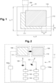
- the second secondary image 112 is thus determined, by the graphics computer 102 or the graphics control device 104a from the data stored in the image buffer device 103, at least by shifting the first secondary image 111, within the first main image 110, a first quantity of pixels ⁇ 1 along the X axis and a second quantity of pixels ⁇ 2 along the Y axis. This is visible on the figure 1 .
- the first quantity of pixels ⁇ 1 and the second quantity of pixels ⁇ 2 also advantageously respond to the following constraints ⁇ 1 /x 1 ⁇ 50% and ⁇ 2 /y 1 ⁇ 50%. Compliance with these provisions is very advantageous for optimizing electric autonomy.
- the graphics control device 104a includes characteristics which can be implemented in an image display system 10 of the invention but can also be implemented independently.
- the graphics control device 104a comprises, in one example, at least one first pixel buffer device 130a connected to a first pixel 130 of the image display screen 104.
- the first pixel buffer device 130a is configured to communicate with a second pixel buffer device 131a itself connected to a second pixel 131 of the screen d image display 104.
- the first pixel buffer device 130a is configured to store a first set of information relating to the first pixel 130.
- the second pixel buffer device 131a is also configured to store a second set of information relating to the second pixel 131.
- the first pixel buffer device 130a is further capable of receiving the second set of information from the second pixel buffer device 131a in a bidirectional manner.
- the second set of information replaces the first set of information within the first pixel buffer device 130a when the image display screen 104 switches from displaying the first secondary image 111 to the second secondary image 112.
- This architecture is advantageous for improving display latency. In fact, the transmission of sets of information, calculated in advance, takes place step by step following a single signal. This architecture is particularly advantageous in combination with the calculation of secondary images 111, 112 which requires low display latency.
- the first set of information relating to the first pixel 130 corresponds to a first color and/or a first light intensity to be displayed by the first pixel 130.
- the second set of information relating to the second pixel 131 corresponds to a second color and/or a second light intensity to be displayed by the second pixel 131.
- the pixel buffer devices 130a, 131a are for example composed of one or more volatile memories.
- the first pixel buffer device 130a and/or the second pixel buffer device 131a are configured to communicate with one or more digital analog converters 140, otherwise called DACs according to the English expression “Digital Analogie Converter”.
- the digital-to-analog converters 140 are capable of converting a digital message, coming from the first pixel buffer device 130a and/or the second pixel buffer device 131a, into a voltage or an electric current supplying the first pixel 130 or the second pixel respectively. 131.
- This process is advantageous because it reduces the latency between the display and the user's movement.
- the second secondary image 112 is a second part of the first main image 110, included entirely in the first main image 110, and offset within the first main image 110 relative to the first secondary image 111 as a function of at least the second parameter of user 121.
- the first main image 110 comprises a first dimension x 1 and a second dimension y 1 expressed in pixels, or in other words, corresponding respectively to first and second numbers of bright pixels.
- the first dimension x 1 and second dimension y 1 are considered respectively along a first axis X and a second axis Y taken from the main image 110 and perpendicular to each other.
- the method then comprises a step g) of determining, by the graphic computer 102, as a function of the second parameter of the user 121, a first quantity of pixels ⁇ 1 along the axis implemented prior to step f).
- the first secondary image 111 and the second secondary image 112 are offset by this first quantity of pixels ⁇ 1 within the main image 110.
- Step g) also consists of the determination by the graphic computer 102 of a second quantity of pixels ⁇ 2 along the Y axis.
- the first secondary image 111 and the second secondary image 112 are offset by the second quantity of pixels ⁇ 2 within the main image 110.
- the first quantity of pixels ⁇ 1 and the second quantity of pixels ⁇ 2 also meet the following constraints ⁇ 1 /x 1 ⁇ 50% and ⁇ 2 /y 1 ⁇ 50%. These constraints are advantageous in order to obtain improved electrical autonomy and reduce the cost of computing equipment.
- the invention also relates to a virtual reality mask 11 comprising an image display system 10 as described above.
- THE figure 2 And 3 illustrate such a virtual reality mask 11.
- a virtual reality mask 11 thus configured has increased electrical autonomy and a satisfactory display speed for the comfort of the user wearing it, all for a reduced price.
Landscapes
- Engineering & Computer Science (AREA)
- Physics & Mathematics (AREA)
- Theoretical Computer Science (AREA)
- General Physics & Mathematics (AREA)
- Computer Hardware Design (AREA)
- General Engineering & Computer Science (AREA)
- Human Computer Interaction (AREA)
- Optics & Photonics (AREA)
- Computer Graphics (AREA)
- Controls And Circuits For Display Device (AREA)
- Control Of Indicators Other Than Cathode Ray Tubes (AREA)
Description
- La présente invention concerne un système de visualisation d'images.
- L'invention concerne également un procédé de commande d'un système de visualisation d'images.
- L'invention concerne également un masque de réalité virtuelle comportant un système de visualisation d'images.
- Dans le domaine des masques de réalité virtuelle, il est connu qu'une latence trop élevée entre le mouvement de la tête et l'affichage de l'image correspondante engendre un inconfort chez un utilisateur du masque de réalité virtuelle lors de ses mouvements.
- Une solution connue consiste à augmenter la fréquence de rafraîchissement des images. Cependant, cette solution consomme beaucoup d'énergie et limite l'autonomie électrique d'utilisation. Les calculateurs nécessaires sont en outre onéreux, ce qui grève financièrement l'attractivité de la solution.
- Une autre solution connue consiste à faire clignoter les images et de les afficher seulement une partie du temps, par exemple avec un ratio de 10%, le reste de l'image perçue étant interpolé par le cerveau de l'utilisateur. Outre le manque de précision des images ainsi produites, cela engendre une baisse importante de la luminosité des images.
- Les documents
US 2015/379772 A1 ,US 2018/365882 A1 ,US 2015/002542 A1 ,US 2018/182273 A1 etUS 2017/228015 A1 décrivent des systèmes d'affichage de Head Mounted Display configurés afin de stocker une image de grande taille dans une première mémoire puis d'extraire et afficher une image de plus petite taille. Cette plus petite image est obtenue par une technique dite de warping. Le documentUS 2015/145877 A1 décrit une méthode de déroulement, dite scrolling, dans laquelle une image est déplacée en mémoire par une recopie. - La présente invention a pour but de fournir une solution de visualisation d'images, notamment d'images de réalité virtuelle, permettant de répondre à tout ou partie des problèmes présentés ci-avant.
- Notamment, un but est de fournir une solution répondant à au moins l'un des objectifs suivants :
- obtenir une réactivité de l'affichage des images satisfaisante ;
- obtenir une intensité lumineuse convenable de l'affichage des images ;
- obtenir une autonomie électrique des systèmes de visualisation d'images admissible ;
- fournir une solution restant économique.
- la deuxième image secondaire étant constituée par une deuxième partie de l'image principale, incluse entièrement dans la première image principale et décalée au sein de la première image principale par rapport à la première image secondaire en fonction d'au moins un deuxième paramètre de l'utilisateur déterminé par l'analyseur de paramètre d'utilisateur à la suite d'un premier mouvement de l'utilisateur ;
- le dispositif de commande graphique comprenant au moins un premier dispositif tampon de pixel relié à un premier pixel de l'écran d'affichage d'images, le premier dispositif tampon de pixel étant configuré pour communiquer avec un deuxième dispositif tampon de pixel relié à un deuxième pixel de l'écran d'affichage d'images, le premier dispositif tampon de pixel étant configuré pour stocker un premier ensemble d'informations relatif au premier pixel,
- le deuxième dispositif tampon de pixel étant configuré pour stocker un deuxième ensemble d'informations relatif au deuxième pixel,
- le premier dispositif tampon de pixel étant apte à recevoir le deuxième ensemble d'informations depuis le deuxième dispositif tampon de pixel et le deuxième ensemble d'informations venant remplacer le premier ensemble d'informations au sein du premier dispositif tampon de pixel lorsque l'écran d'affichage d'images passe de l'affichage de la première image secondaire à la deuxième image secondaire.
- Certains aspects préférés mais non limitatifs du système de visualisation d'images sont les suivants.
- Dans une mise en oeuvre du système de visualisation d'images, la première image principale comprend une première dimension x1 et une deuxième dimension y1 correspondant respectivement à des premiers et des deuxièmes nombres de pixels lumineux de l'écran et considérées respectivement selon un premier axe X et un deuxième axe Y de la première image principale perpendiculaires entre eux, et dans lequel la deuxième image secondaire est déterminée au moins en décalant la première image secondaire, au sein de la première image principale, d'une première quantité de pixels Δ1 selon l'axe X et d'une deuxième quantité de pixels Δ2 selon l'axe Y, la première quantité de pixels Δ1 et la deuxième quantité de pixels Δ2 étant déterminées par le calculateur graphique en fonction d'au moins le deuxième paramètre de l'utilisateur, la première quantité de pixels Δ1 et la deuxième quantité de pixels Δ2 étant tels que Δ1/x1 <50% et Δ2/y1 <50%.
- Dans une mise en oeuvre du système de visualisation d'images, les informations du premier ensemble d'informations relatif au premier pixel sont représentatives d'une première couleur et/ou d'une première intensité lumineuse à afficher par le premier pixel, et dans lequel les informations du deuxième ensemble d'informations relatif au deuxième pixel sont représentatives d'une deuxième couleur et/ou d'une deuxième intensité lumineuse à afficher par le deuxième pixel.
- Dans une mise en oeuvre du système de visualisation d'images, au moins un élément choisi dans le groupe comprenant le premier dispositif tampon de pixel et le deuxième dispositif tampon de pixel est configuré pour communiquer avec un convertisseur numérique analogique apte à convertir un message numérique, en provenance d'un élément choisi dans le groupe comprenant le premier dispositif tampon de pixel et le deuxième dispositif tampon de pixel, en une tension ou en un courant électrique alimentant respectivement le premier pixel ou le deuxième pixel.
- Dans une mise en oeuvre du système de visualisation d'images, au moins un paramètre d'utilisateur choisi dans le groupe comprenant le premier, le deuxième et le troisième paramètres d'utilisateur, consiste au moins en une information choisie parmi un mouvement de l'utilisateur, une position de la tête de l'utilisateur, une direction principale de vision de l'utilisateur et un champ de vision de l'utilisateur.
- L'invention porte également sur la mise en oeuvre d'un procédé de commande d'un système de visualisation d'images dans lequel le système de visualisation d'images comporte au moins un analyseur de paramètre d'utilisateur configuré pour déterminer au moins un paramètre associé à un utilisateur du système de visualisation d'images ; un écran d'affichage d'images ayant une pluralité de pixels lumineux répartis de manière matricielle ; un dispositif de commande graphique apte à communiquer avec un dispositif tampon d'image et configuré pour commander un affichage d'images sur l'écran d'affichage d'images ; le dispositif de commande graphique comprenant au moins un premier dispositif tampon de pixel relié à un premier pixel de l'écran d'affichage d'images, le premier dispositif tampon de pixel étant configuré pour communiquer avec un deuxième dispositif tampon de pixel relié à un deuxième pixel de l'écran d'affichage d'images,
- le premier dispositif tampon de pixel étant configuré pour stocker un premier ensemble d'informations relatif au premier pixel,
- le deuxième dispositif tampon de pixel étant configuré pour stocker un deuxième ensemble d'informations relatif au deuxième pixel ;
- le procédé comprenant les étapes suivantes :
- a) détermination d'au moins un premier paramètre de l'utilisateur par l'analyseur de paramètre d'utilisateur ;
- b) détermination, par au moins un calculateur graphique , d'au moins une première image principale susceptible d'être visualisée au moins en partie sur l'écran d'affichage d'images, où la première image principale correspond à une première zone d'une scène principale ;
- c) stockage de la première image principale calculée par le calculateur graphique dans le dispositif tampon d'image ;
- d) commande, par le dispositif de commande graphique, de l'affichage par l'écran d'affichage d'images d'une première image secondaire constituée par une première partie de la première image principale incluse entièrement dans la première image principale et positionnée au sein de la première image principale en fonction d'au moins le premier paramètre de l'utilisateur ;
- e) détermination, par l'analyseur de paramètre d'utilisateur, d'au moins un deuxième paramètre de l'utilisateur à la suite d'un premier mouvement de l'utilisateur ;
- f) commande, par le dispositif de commande graphique, de l'affichage sur l'écran d'affichage d'images d'une deuxième image secondaire se substituant à la première image secondaire dans l'écran d'affichage d'images, la deuxième image secondaire étant constituée par une deuxième partie de la première image principale, incluse entièrement dans la première image principale, et décalée au sein de la première image principale par rapport à la première image secondaire en fonction d'au moins le deuxième paramètre de l'utilisateur ;
- le premier dispositif tampon de pixel étant apte à recevoir le deuxième ensemble d'informations depuis le deuxième dispositif tampon de pixel et le deuxième ensemble d'informations venant remplacer le premier ensemble d'informations au sein du premier dispositif tampon de pixel lorsque l'écran d'affichage d'images passe de l'affichage de la première image secondaire à la deuxième image secondaire.
- Certains aspects préférés mais non limitatifs du procédé de commande sont les suivants.
- Dans une mise en oeuvre du procédé, la première image principale comprend une première dimension x1 et une deuxième dimension y1 correspondant respectivement à des premiers et des deuxièmes nombres de pixels lumineux de l'écran et considérées respectivement selon un premier axe X et un deuxième axe Y pris sur l'image principale perpendiculaires entre eux, le procédé comportant l'étape suivante, mise en oeuvre préalablement à l'étape f) :
- g) détermination, par le calculateur graphique, en fonction du deuxième paramètre de l'utilisateur:
- d'une première quantité de pixels Δ1 selon l'axe X, la première image secondaire et la deuxième image secondaire étant décalées de la première quantité de pixels Δ1 au sein de l'image principale, et
- d'une deuxième quantité de pixels Δ2 selon l'axe Y, la première image secondaire et la deuxième image secondaire étant décalées de la deuxième quantité de pixels Δ2 au sein de l'image principale,
- la première quantité de pixels Δ1 et la deuxième quantité de pixels Δ2 étant telles que Δ1/x1 <50% et Δ2/y1 <50%.
- L'invention porte également sur un masque de réalité virtuelle comportant un tel système de visualisation d'images.
- D'autres aspects, buts, avantages et caractéristiques de l'invention apparaîtront mieux à la lecture de la description détaillée suivante de modes de réalisation préférés de celle-ci, donnée à titre d'exemple non limitatif, et faite en référence aux dessins annexés sur lesquels :
- [
Fig. 1 ] est une vue schématique d'une image principale comprenant une première image secondaire et une deuxième image secondaire. - [
Fig. 2 ] est une vue schématique d'un exemple de réalisation d'un système de visualisation d'images selon l'invention. - [
Fig. 3 ] est une vue schématique d'un exemple de réalisation d'un dispositif de commande graphique du système de visualisation d'images. - [
Fig. 4 ] est une vue schématique d'un exemple de réalisation d'un dispositif de commande graphique du système de visualisation d'images. - Sur les
figures 1 à 4 annexées et dans la suite de la description, des éléments identiques ou similaires en terme fonctionnel sont repérés par les mêmes références. De plus, les différents éléments ne sont pas représentés à l'échelle de manière à privilégier la clarté des figures pour en faciliter la compréhension. Par ailleurs, les différents modes de réalisation et variantes ne sont pas exclusifs les uns des autres et peuvent, au contraire, être combinés entre eux. - Dans la suite de la description, sauf indication contraire, les termes « sensiblement », « environ », « globalement » et « de l'ordre de » signifient « à 10 % près ».
- L'invention porte en premier lieu sur un système de visualisation d'images 10, illustré au moins en partie sur les
figures 1 à 3 , comportant au moins un analyseur de paramètre d'utilisateur 101. L'analyseur de paramètre d'utilisateur 101 est configuré pour déterminer au moins un paramètre associé à un utilisateur du système de visualisation d'images 10. Les paramètres associés à l'utilisateur consistent au moins en une information choisie parmi un mouvement de l'utilisateur et/ou une position de la tête et/ou des yeux de l'utilisateur et/ou une direction principale de vision de l'utilisateur et/ou encore un champ de vision de l'utilisateur. L'analyseur de paramètre d'utilisateur 101 peut comprendre des capteurs de mouvement tels que des accéléromètres ou bien des gyroscopes. L'analyseur de paramètre d'utilisateur 101 peut comprendre des moyens pour déterminer une direction principale de vision de l'utilisateur ou encore un champ de vision de l'utilisateur tels que des caméras, par exemple des caméras fonctionnant dans le domaine de l'infra-rouge couplées avec des sources lumineuses adaptées à l'infra-rouge. Les termes « direction principale de vision » font référence à la direction vers laquelle l'utilisateur regarde de façon nette. Le champ de vision représente l'ensemble visuel perçu par les yeux de l'utilisateur de façon nette ou plus floue, il représente un angle d'environ 180° autour de l'orientation des yeux. De façon générale, la partie de vision nette d'un utilisateur classique correspond à environ une vingtaine de degrés suivant l'orientation des yeux de l'utilisateur. Il peut donc être important de déterminer à quelques degrés prés la direction principale de vision de l'utilisateur afin de pouvoir lui présenter par affichage en retour une image correspondante adaptée. - Le système de visualisation d'images 10 comprend également un écran d'affichage d'images 104 ayant une pluralité de pixels lumineux répartis selon une matrice. Les pixels lumineux sont commandés pour représenter des images. L'homme du métier pourra mettre en oeuvre ses connaissances classiques pour obtenir ces pixels lumineux et les circuits de base associés.
- Le système de visualisation d'images 10 comprend également au moins un calculateur graphique 102 configuré pour calculer au moins une première image principale 110. Le calculateur graphique 102 est par exemple appelé « Graphics Processing Unit » selon une terminologie anglosaxonne appropriée. Le calculateur graphique 102 peut par exemple comprendre des microprocesseurs. La première image principale 110 est susceptible d'être visualisée au moins en partie « sur » ou de façon équivalente « dans » ou « par » l'écran d'affichage d'images 104. La première image principale 110 est, par exemple, représentative d'une première zone d'une scène principale. La scène principale représente, par exemple, un environnement statique ou mouvant, virtuel ou non, dans lequel l'utilisateur est susceptible d'évoluer virtuellement. L'utilisateur peut ainsi évoluer de façon statique, par exemple en bougeant uniquement ses yeux ou sa tête ou bien en effectuant des mouvements impliquant tout le corps. Par exemple, en bougeant fortement la tête, l'utilisateur doit pouvoir visualiser un changement d'une première à une deuxième zone différente de la scène principale comme il pourrait le faire dans la réalité. Dans un autre exemple, en bougeant faiblement la tête, l'utilisateur doit pouvoir visualiser un changement faible d'une même zone de la scène principale. Afin de calculer les images correspondant aux différents mouvements de l'utilisateur faibles ou amples avec une fluidité satisfaisante sans perte de luminosité et sans retard, il peut être avantageux d'utiliser l'architecture détaillée ci-après.
- Ainsi, le système de visualisation d'images 10 comprend également au moins un dispositif tampon d'image 103 configuré pour stocker au moins la première image principale 110 calculée par le calculateur graphique 102. Par exemple, le dispositif tampon d'image 103 comprend une ou plusieurs mémoires réinscriptibles de types FLASH, RAM ou équivalent.
- Le dispositif tampon d'image 103 communique avec un dispositif de commande graphique 104a. Ainsi, le dispositif de commande graphique 104a peut venir utiliser et traiter des données, par exemple de la première image principale 110 ou d'une deuxième image principale 210, stockées temporairement dans le dispositif tampon d'image 103. Le dispositif de commande graphique 104a comprend par exemple des moyens de calculs tels que des microprocesseurs. Comme illustré sur les
figures 1 et 2 , le dispositif de commande graphique 104a est configuré pour commander un affichage d'au moins une première image secondaire 111 sur l'écran d'affichage d'images 104. - La première image secondaire 111 est une première partie de la première image principale 110 incluse entièrement dans la première image principale 110. La première image secondaire 111 est positionnée au sein de la première image principale 110 en fonction d'au moins un premier paramètre de l'utilisateur 120 déterminé par l'analyseur de paramètre d'utilisateur 101. La première image secondaire 111 correspond ainsi, par exemple, à l'image de la scène principale vue dans la direction principale de vision de l'utilisateur.
- Il est avantageux de calculer une première image principale 110 plus large que la première image secondaire 111 qui est affichée sur l'écran d'affichage d'image 104. En effet, les vitesses de calculs par les calculateurs graphiques classiques ou de faible consommation électrique sont plus faibles que les vitesses d'affichage sur l'écran d'affichage d'image 104. Ainsi, en calculant une première ou une deuxième images principales 110, 210 plus large que les images secondaires 111, 112, il est possible ensuite d'en déduire directement, ou avec des calculs simplifiés, effectués par le dispositif de commande graphique 104a, plusieurs images secondaires 111, 112 qui seront affichées plus rapidement que si elles avaient dû être recalculées entièrement séparément.
- Dans son mode de fonctionnement standard, le calculateur graphique 102 fournit des images de la scène principale dans la direction principale de vision de l'utilisateur à une fréquence définie par le système (par exemple 60Hz, 120Hz). Une première image principale 110 calculée par le calculateur graphique 102 est ainsi fournie. La partie de la première image principale 110 vue par l'utilisateur est la première image secondaire 111 extraite par le dispositif de commande graphique 104a. Une seconde image principale 210 sera fournie après la période définie par la fréquence du système et correspondra à la scène réactualisée en tenant compte de la direction principale de vision de l'utilisateur réactualisée. Dans l'attente de l'image 210 et en s'appuyant sur l'analyseur de paramètre d'utilisateur 101, une deuxième image secondaire 112 est affichée à l'utilisateur correspondant à sa direction principale de vision actuelle 121. Cette deuxième image secondaire 112 est obtenue par un simple décalage au sein de la première image principale 110, ou par l'application d'algorithmes simples sur cette image 110. Le système permet donc de maintenir l'illusion du mouvement de l'utilisateur entre les deux images principales 110, 210 successives. Ce système offre un gain important en consommation d'énergie et ressources systèmes nécessaires pour le calcul des images comparé à une solution où le calculateur 102 fournirait les images à un rythme où les images secondaires 111, 112 ne seraient plus nécessaires. D'autre part, les images secondaires 111, 112 ainsi générées permettent le remplacement total ou partiel de l'insertion d'images noires augmentant ainsi avantageusement la luminosité de l'écran.
- Il est considéré ici une seule première image secondaire 111 et une seule image secondaire 112 se substituant à la première image secondaire 111. Cependant, il peut y avoir de nombreuses images secondaires construites dans une image principale 110, 210 du moment qu'elles sont incluses entièrement dans l'image principale 110, 210 en question.
- Dans un exemple de mise en oeuvre du décalage entre la première image secondaire 111 et la deuxième image secondaire 112 au sein de l'image principale 110, il est considéré une première image principale 110 comprenant une première dimension x1 et une deuxième dimension y1 exprimées en pixels ou, autrement dit, correspondant respectivement à des premiers et des deuxièmes nombres de pixels lumineux de l'écran d'affichage. Les premières et deuxièmes dimensions x1 et y1 sont considérées respectivement selon un premier axe X et un deuxième axe Y de la première image principale 110, perpendiculaires entre eux. La deuxième image secondaire 112 est ainsi déterminée, par le calculateur graphique 102 ou le dispositif de commande graphique 104a à partir des données stockées dans le dispositif tampon d'image 103, au moins en décalant la première image secondaire 111, au sein de la première image principale 110, d'une première quantité de pixels Δ1 selon l'axe X et d'une deuxième quantité de pixels Δ2 selon l'axe Y. Ceci est visible sur la
figure 1 . La première quantité de pixels Δ1 et la deuxième quantité de pixels Δ2 répondent également avantageusement aux contraintes suivantes Δ1/x1 <50% et Δ2/y1 <50%. Le respect de ces dispositions est très avantageux pour optimiser l'autonomie électrique. - Dans le paragraphe suivant, le dispositif de commande graphique 104a comprend des caractéristiques qui peuvent s'implémenter dans un système de visualisation d'images 10 de l'invention mais peuvent également être mises en oeuvre de façon indépendante.
- Comme illustré sur la
figure 3 , le dispositif de commande graphique 104a comprend, dans un exemple, au moins un premier dispositif tampon de pixel 130a relié à un premier pixel 130 de l'écran d'affichage d'images 104. Le premier dispositif tampon de pixel 130a est configuré pour communiquer avec un deuxième dispositif tampon de pixel 131a lui-même relié à un deuxième pixel 131 de l'écran d'affichage d'images 104. Le premier dispositif tampon de pixel 130a est configuré pour stocker un premier ensemble d'informations relatif au premier pixel 130. Le deuxième dispositif tampon de pixel 131a est également configuré pour stocker un deuxième ensemble d'informations relatif au deuxième pixel 131. Le premier dispositif tampon de pixel 130a est en outre apte à recevoir le deuxième ensemble d'informations depuis le deuxième dispositif tampon de pixel 131a et ce de façon bidirectionnelle. Le deuxième ensemble d'informations vient remplacer le premier ensemble d'informations au sein du premier dispositif tampon de pixel 130a lorsque l'écran d'affichage d'images 104 passe de l'affichage de la première image secondaire 111 à la deuxième image secondaire 112. Cette architecture est avantageuse pour améliorer le temps de latence d'affichage. En effet, la transmission des ensembles d'informations, calculés au prélable, se fait de proche en proche à la suite d'un seul signal. Cette architecture est particulièrement avantageuse en combinaison avec le calcul des images secondaires 111, 112 qui demande une latence d'affichage faible. - Dans un exemple, le premier ensemble d'informations relatif au premier pixel 130 correspond à une première couleur et/ou une première intensité lumineuse à afficher par le premier pixel 130. Dans le même exemple, le deuxième ensemble d'informations relatif au deuxième pixel 131 correspond à une deuxième couleur et/ou une deuxième intensité lumineuse à afficher par le deuxième pixel 131. Les dispositifs tampon de pixel 130a, 131a sont par exemple composés d'une ou plusieurs mémoires volatiles.
- Dans un exemple illustré sur la
figure 4 , le premier dispositif tampon de pixel 130a et/ou le deuxième dispositif tampon de pixel 131a sont configurés pour communiquer avec un ou plusieurs convertisseurs numériques analogiques 140 autrement appelés DAC selon l'expression anglaise « Digital Analogie Converter ». Les convertisseurs numériques analogiques 140 sont aptes à convertir un message numérique, venant du premier dispositif tampon de pixel 130a et/ou du deuxième dispositif tampon de pixel 131a, en une tension ou un courant électrique venant alimenter respectivement le premier pixel 130 ou le deuxième pixel 131. - L'invention concerne également un procédé de commande d'un système de visualisation d'images 10, notamment comme celui décrit précédemment. Ce procédé peut se visualiser sur la
figure 2 . Le procédé comprend les étapes suivantes : - a) détermination d'au moins un premier paramètre de l'utilisateur 120 par l'analyseur de paramètre d'utilisateur 101 ;
- b) détermination, par au moins un calculateur graphique 102, d'au moins une première image principale 110 susceptible d'être visualisée au moins en partie sur l'écran d'affichage d'images 104, la première image principale 110 correspondant à une première zone d'une scène principale ;
- c) stockage de la première image principale 110 calculée par le calculateur graphique 102 dans le dispositif tampon d'image 103 ;
- d) commande, par le dispositif de commande graphique 104a, de l'affichage par l'écran d'affichage d'images 104 de la première image secondaire 111, la première image secondaire 111 étant une première partie de la première image principale 110 incluse entièrement dans la première image principale 110 et positionnée au sein de la première image principale 110 en fonction d'au moins le premier paramètre de l'utilisateur 120.
- Ce procédé est avantageux car il permet de réduire la latence entre l'affichage et le mouvement de l'utilisateur.
- Le procédé comporte également les étapes supplémentaires suivantes :
- e) détermination, par l'analyseur de paramètre d'utilisateur 101, à la suite d'un premier mouvement de l'utilisateur, d'au moins un deuxième paramètre de l'utilisateur 121 ;
- f) commande, par le dispositif de commande graphique 104a, de l'affichage sur l'écran d'affichage d'images 104 d'une deuxième image secondaire 112, se substituant à la première image secondaire 111 dans l'écran d'affichage d'images 104.
- La deuxième image secondaire 112 est une deuxième partie de la première image principale 110, incluse entièrement dans la première image principale 110, et décalée au sein de la première image principale 110 par rapport à la première image secondaire 111 en fonction d'au moins le deuxième paramètre de l'utilisateur 121.
- Ceci est avantageux car lors d'un mouvement de faible amplitude de l'utilisateur alors les images secondaires suffisent pour suivre par exemple la direction principale de vision de l'utilisateur, et ce, sans avoir à recalculer une deuxième image principale 210. L'autonomie électrique s'en trouve accrue et les besoins en puissance de calcul limités ce qui fait baisser de fait les coûts de matériel.
- Dans un exemple de mise en oeuvre, la première image principale 110 comprend une première dimension x1 et une deuxième dimension y1 exprimées en pixels, ou autrement dit, correspondant respectivement à des premiers et des deuxièmes nombres de pixels lumineux. Les première dimension x1 et deuxième dimension y1 sont considérées respectivement selon un premier axe X et un deuxième axe Y pris sur l'image principale 110 et perpendiculaires entre eux. Le procédé comporte alors une étape g) de détermination, par le calculateur graphique 102, en fonction du deuxième paramètre de l'utilisateur 121, d'une première quantité de pixels Δ1 selon l'axe X. L'étape g) est mise en oeuvre préalablement à l'étape f).
- La première image secondaire 111 et la deuxième image secondaire 112 sont décalées de cette première quantité de pixels Δ1 au sein de l'image principale 110. L'étape g) consiste également en la détermination par le calculateur graphique 102 d'une deuxième quantité de pixels Δ2 selon l'axe Y. La première image secondaire 111 et la deuxième image secondaire 112 sont décalées de la deuxième quantité de pixels Δ2 au sein de l'image principale 110. La première quantité de pixels Δ1 et la deuxième quantité de pixels Δ2 répondent également aux contraintes suivantes Δ1/x1 <50% et Δ2/y1 <50%. Ces contraintes sont avantageuses pour permettre d'obtenir une autonomie électrique améliorée et diminuer le coût du matériel de calcul.
- L'invention concerne également un masque de réalité virtuelle 11 comportant un système de visualisation d'images 10 comme décrit précédemment. Les
figures 2 et3 illustrent un tel masque de réalité virtuelle 11. Un masque de réalité virtuelle 11 ainsi configuré présente une autonomie électrique accrue et une vitesse d'affichage satisfaisante pour le confort de l'utilisateur le portant, le tout pour un prix réduit.
Claims (8)
- Système de visualisation d'images (10), comportant :- au moins un analyseur de paramètre d'utilisateur (101) configuré pour déterminer au moins un paramètre associé à un utilisateur du système de visualisation d'images (10) ;- un écran d'affichage d'images (104) comportant une pluralité de pixels lumineux répartis de manière matricielle ;- au moins un calculateur graphique (102) configuré pour calculer au moins une première image principale (110) susceptible d'être visualisée au moins en partie sur l'écran d'affichage d'images (104) et représentative d'une première zone d'une scène principale ;- au moins un dispositif tampon d'image (103) configuré pour stocker au moins la première image principale (110) calculée par le calculateur graphique (102) ;- un dispositif de commande graphique (104a) apte à communiquer avec le dispositif tampon d'image (103) et configuré pour commander un affichage d'au moins une première image secondaire (111) sur l'écran d'affichage d'images (104), la première image secondaire (111) étant constituée par une première partie de la première image principale (110) incluse entièrement dans la première image principale (110) et positionnée au sein de la première image principale (110) en fonction d'au moins un premier paramètre de l'utilisateur (120) déterminé par l'analyseur de paramètre d'utilisateur (101) ;le dispositif de commande graphique (104a) étant configuré pour commander l'affichage sur l'écran d'affichage d'images (104) d'une deuxième image secondaire (112) se substituant à la première image secondaire (111), etla deuxième image secondaire (112) étant constituée par une deuxième partie de l'image principale (110), incluse entièrement dans la première image principale (110) et décalée au sein de la première image principale (110) par rapport à la première image secondaire (111) en fonction d'au moins un deuxième paramètre de l'utilisateur (121) déterminé par l'analyseur de paramètre d'utilisateur (101) à la suite d'un premier mouvement de l'utilisateur ;caractérisé en ce que :le dispositif de commande graphique (104a) comprend au moins un premier dispositif tampon de pixel (130a) relié à un premier pixel (130) de l'écran d'affichage d'images (104), le premier dispositif tampon de pixel (130a) étant configuré pour communiquer avec un deuxième dispositif tampon de pixel (131a) relié à un deuxième pixel (131) de l'écran d'affichage d'images (104),le premier dispositif tampon de pixel (130a) est configuré pour stocker un premier ensemble d'informations relatif au premier pixel (130),le deuxième dispositif tampon de pixel (131a) est configuré pour stocker un deuxième ensemble d'informations relatif au deuxième pixel (131), etle premier dispositif tampon de pixel (130a) est apte à recevoir le deuxième ensemble d'informations depuis le deuxième dispositif tampon de pixel (131a) et le deuxième ensemble d'informations venant remplacer le premier ensemble d'informations au sein du premier dispositif tampon de pixel (130a) lorsque l'écran d'affichage d'images (104) passe de l'affichage de la première image secondaire (111) à la deuxième image secondaire (112).
- Système de visualisation d'images (10) selon la revendication 1, dans lequel la première image principale (110) comprend une première dimension x1 et une deuxième dimension y1 correspondant respectivement à des premiers et des deuxièmes nombres de pixels lumineux de l'écran et considérées respectivement selon un premier axe (X) et un deuxième axe (Y) de la première image principale (110) perpendiculaires entre eux, et dans lequel la deuxième image secondaire (112) est déterminée au moins en décalant la première image secondaire (111), au sein de la première image principale (110), d'une première quantité de pixels Δ1 selon le premier axe (X) et d'une deuxième quantité de pixels Δ2 selon le deuxième axe (Y),la première quantité de pixels Δ1 et la deuxième quantité de pixels Δ2 étant déterminées par le calculateur graphique (102) en fonction d'au moins le deuxième paramètre de l'utilisateur (121),la première quantité de pixels Δ1 et la deuxième quantité de pixels Δ2 étant tels que Δ 1/x1 <50% et Δ2/y1 <50%.
- Système de visualisation d'images (10) selon l'une quelconque des revendications 1 ou 2, dans lequel les informations du premier ensemble d'informations relatif au premier pixel (130) sont représentatives d'une première couleur et/ou d'une première intensité lumineuse à afficher par le premier pixel (130),
et dans lequel les informations du deuxième ensemble d'informations relatif au deuxième pixel (131) sont représentatives d'une deuxième couleur et/ou d'une deuxième intensité lumineuse à afficher par le deuxième pixel (131). - Système de visualisation d'images (10) selon la revendication 3, comprenant un convertisseur numérique analogique (140) et dans lequel au moins un élément choisi dans le groupe comprenant le premier dispositif tampon de pixel (130a) et le deuxième dispositif tampon de pixel (131a) est configuré pour communiquer avec le convertisseur numérique analogique (140), lequel est apte à convertir un message numérique, en provenance d'un élément choisi dans le groupe comprenant le premier dispositif tampon de pixel (130a) et le deuxième dispositif tampon de pixel (131a), en une tension ou en un courant électrique alimentant respectivement le premier pixel (130) ou le deuxième pixel (131).
- Système de visualisation d'images (10) selon l'une des revendications 1 à 4, dans lequel au moins un paramètre d'utilisateur choisi dans le groupe comprenant le premier et le deuxième paramètres d'utilisateur, consiste au moins en une information choisie parmi un mouvement de l'utilisateur, une position de la tête de l'utilisateur, une direction principale de vision de l'utilisateur et un champ de vision de l'utilisateur.
- Procédé de commande d'un système de visualisation d'images (10) dans lequel le système de visualisation d'images (10) comporte :- au moins un analyseur de paramètre d'utilisateur (101) configuré pour déterminer au moins un paramètre associé à un utilisateur du système de visualisation d'images (10) ;- un écran d'affichage d'images (104) ayant une pluralité de pixels lumineux répartis de manière matricielle ;- un dispositif de commande graphique (104a) apte à communiquer avec un dispositif tampon d'image (103) et configuré pour commander un affichage d'images sur l'écran d'affichage d'images (104) ;le procédé comprenant les étapes suivantes :a) détermination d'au moins un premier paramètre de l'utilisateur (120) par l'analyseur de paramètre d'utilisateur (101) ;b) détermination, par au moins un calculateur graphique (102), d'au moins une première image principale (110) susceptible d'être visualisée au moins en partie sur l'écran d'affichage d'images (104), où la première image principale (110) correspond à une première zone d'une scène principale ;c) stockage de la première image principale (110) calculée par le calculateur graphique (102) dans le dispositif tampon d'image (103) ;d) commande, par le dispositif de commande graphique (104a), de l'affichage par l'écran d'affichage d'images (104) d'une première image secondaire (111) constituée par une première partie de la première image principale (110) incluse entièrement dans la première image principale (110) et positionnée au sein de la première image principale (110) en fonction d'au moins le premier paramètre de l'utilisateur (120) ;e) détermination, par l'analyseur de paramètre d'utilisateur (101), d'au moins un deuxième paramètre de l'utilisateur (121) à la suite d'un premier mouvement de l'utilisateur ; etf) commande, par le dispositif de commande graphique (104a), de l'affichage sur l'écran d'affichage d'images (104) d'une deuxième image secondaire (112) se substituant à la première image secondaire (111) dans l'écran d'affichage d'images (104), la deuxième image secondaire (112) étant constituée par une deuxième partie de la première image principale (110), incluse entièrement dans la première image principale (110), et décalée au sein de la première image principale (110) par rapport à la première image secondaire (111) en fonction d'au moins le deuxième paramètre de l'utilisateur (121), caractérisé en ce que :le dispositif de commande graphique (104a) comprend au moins un premier dispositif tampon de pixel (130a) relié à un premier pixel (130) de l'écran d'affichage d'images (104), le premier dispositif tampon de pixel (130a) étant configuré pour communiquer avec un deuxième dispositif tampon de pixel (131a) relié à un deuxième pixel (131) de l'écran d'affichage d'images (104),le premier dispositif tampon de pixel (130a) est configuré pour stocker un premier ensemble d'informations relatif au premier pixel (130),le deuxième dispositif tampon de pixel (131a) est configuré pour stocker un deuxième ensemble d'informations relatif au deuxième pixel (131),le premier dispositif tampon de pixel (130a) recevant le deuxième ensemble d'informations depuis le deuxième dispositif tampon de pixel (131a) et le deuxième ensemble d'informations venant remplacer le premier ensemble d'informations au sein du premier dispositif tampon de pixel (130a) lorsque l'écran d'affichage d'images (104) passe de l'affichage de la première image secondaire (111) à la deuxième image secondaire (112).
- Procédé selon la revendication 6, dans lequel la première image principale (110) comprend une première dimension x1 et une deuxième dimension y1 correspondant respectivement à des premiers et des deuxièmes nombres de pixels lumineux de l'écran et considérées respectivement selon un premier axe (X) et un deuxième axe (Y) pris sur l'image principale (110) perpendiculaires entre eux, le procédé comportant l'étape suivante, mise en oeuvre préalablement à l'étape f) :g) détermination, par le calculateur graphique (102), en fonction du deuxième paramètre de l'utilisateur (121):- d'une première quantité de pixels Δ1 selon l'axe (X), la première image secondaire (111) et la deuxième image secondaire (112) étant décalées de la première quantité de pixels Δ1 au sein de l'image principale (110), et- d'une deuxième quantité de pixels Δ2 selon l'axe (Y), la première image secondaire (111) et la deuxième image secondaire (112) étant décalées de la deuxième quantité de pixels (Δ2) au sein de l'image principale (110),la première quantité de pixels Δ1 et la deuxième quantité de pixels Δ2 étant telles que Δ1/x1 <50% et Δ2/y1 <50%.
- Masque de réalité virtuelle (11) comportant un système de visualisation d'images (10) selon l'une quelconque des revendications 1 à 5.
Applications Claiming Priority (2)
| Application Number | Priority Date | Filing Date | Title |
|---|---|---|---|
| FR1907893A FR3098629B1 (fr) | 2019-07-12 | 2019-07-12 | Système de visualisation d’images et procédé de commande |
| PCT/FR2020/051245 WO2021009451A1 (fr) | 2019-07-12 | 2020-07-09 | Système de visualisation d'images et procédé de commande |
Publications (2)
| Publication Number | Publication Date |
|---|---|
| EP3997690A1 EP3997690A1 (fr) | 2022-05-18 |
| EP3997690B1 true EP3997690B1 (fr) | 2024-04-24 |
Family
ID=68211056
Family Applications (1)
| Application Number | Title | Priority Date | Filing Date |
|---|---|---|---|
| EP20750706.2A Active EP3997690B1 (fr) | 2019-07-12 | 2020-07-09 | Système de visualisation d'images et procédé de commande |
Country Status (6)
| Country | Link |
|---|---|
| US (1) | US11880906B2 (fr) |
| EP (1) | EP3997690B1 (fr) |
| JP (1) | JP7498768B2 (fr) |
| KR (1) | KR102808937B1 (fr) |
| FR (1) | FR3098629B1 (fr) |
| WO (1) | WO2021009451A1 (fr) |
Citations (1)
| Publication number | Priority date | Publication date | Assignee | Title |
|---|---|---|---|---|
| US20150145877A1 (en) * | 2013-11-26 | 2015-05-28 | Mstar Semiconductor, Inc. | Frame drawing method, frame updating method and associated mobile electronic device |
Family Cites Families (10)
| Publication number | Priority date | Publication date | Assignee | Title |
|---|---|---|---|---|
| JP2008146495A (ja) * | 2006-12-12 | 2008-06-26 | Sony Corp | 表示制御システム、表示制御装置、表示制御方法および表示制御プログラム、画像出力装置、画像出力方法および画像出力プログラム、ならびに、表示装置 |
| US9443355B2 (en) * | 2013-06-28 | 2016-09-13 | Microsoft Technology Licensing, Llc | Reprojection OLED display for augmented reality experiences |
| US20150379772A1 (en) * | 2014-06-30 | 2015-12-31 | Samsung Display Co., Ltd. | Tracking accelerator for virtual and augmented reality displays |
| US9824498B2 (en) * | 2014-12-30 | 2017-11-21 | Sony Interactive Entertainment Inc. | Scanning display system in head-mounted display for virtual reality |
| JP6511386B2 (ja) * | 2015-11-20 | 2019-05-15 | 株式会社ソニー・インタラクティブエンタテインメント | 情報処理装置および画像生成方法 |
| US10317991B2 (en) * | 2016-02-09 | 2019-06-11 | Google Llc | Pixel adjusting at display controller for electronic display stabilization |
| US10398976B2 (en) * | 2016-05-27 | 2019-09-03 | Samsung Electronics Co., Ltd. | Display controller, electronic device, and virtual reality device |
| KR102927278B1 (ko) * | 2016-12-26 | 2026-02-13 | 엘지디스플레이 주식회사 | 헤드 마운티드 디스플레이 및 그 제어 방법 |
| GB201709752D0 (en) * | 2017-06-19 | 2017-08-02 | Advanced Risc Mach Ltd | Graphics processing systems |
| JP2019054360A (ja) * | 2017-09-14 | 2019-04-04 | セイコーエプソン株式会社 | 電子機器、モーションセンサー、位置変化検出プログラムおよび位置変化検出方法 |
-
2019
- 2019-07-12 FR FR1907893A patent/FR3098629B1/fr not_active Expired - Fee Related
-
2020
- 2020-07-09 WO PCT/FR2020/051245 patent/WO2021009451A1/fr not_active Ceased
- 2020-07-09 EP EP20750706.2A patent/EP3997690B1/fr active Active
- 2020-07-09 US US17/626,181 patent/US11880906B2/en active Active
- 2020-07-09 JP JP2022501034A patent/JP7498768B2/ja active Active
- 2020-07-09 KR KR1020227003506A patent/KR102808937B1/ko active Active
Patent Citations (1)
| Publication number | Priority date | Publication date | Assignee | Title |
|---|---|---|---|---|
| US20150145877A1 (en) * | 2013-11-26 | 2015-05-28 | Mstar Semiconductor, Inc. | Frame drawing method, frame updating method and associated mobile electronic device |
Also Published As
| Publication number | Publication date |
|---|---|
| WO2021009451A1 (fr) | 2021-01-21 |
| JP2022540182A (ja) | 2022-09-14 |
| KR102808937B1 (ko) | 2025-05-16 |
| FR3098629A1 (fr) | 2021-01-15 |
| FR3098629B1 (fr) | 2021-08-13 |
| JP7498768B2 (ja) | 2024-06-12 |
| EP3997690A1 (fr) | 2022-05-18 |
| US20220277410A1 (en) | 2022-09-01 |
| KR20220025075A (ko) | 2022-03-03 |
| US11880906B2 (en) | 2024-01-23 |
Similar Documents
| Publication | Publication Date | Title |
|---|---|---|
| US8817002B2 (en) | Data display adapted for bright ambient light | |
| US12401705B2 (en) | Dynamic user-device upscaling of media streams | |
| US11683593B2 (en) | High dynamic range image capture using single photon avalanche diodes | |
| CN112714356A (zh) | 图像亮度校正方法、装置、设备以及存储介质 | |
| FR2974938A1 (fr) | Systeme avionique a trois ecrans de visualisation pour aeronef | |
| FR2924212A1 (fr) | Panneau de commande virtuel de centrales d'attitude aeronautique | |
| US20240087247A1 (en) | Systems and method for rendering of virtual objects | |
| Hamilton-Fletcher et al. | Accuracy and usability of smartphone-based distance estimation approaches for visual assistive technology development | |
| WO2023069165A1 (fr) | Systèmes et procédés de modification sélective de vitesse de déclenchement dans des diodes à avalanche à photon unique | |
| CN110728934A (zh) | 一种全息投影亮度调节系统、方法、车辆及存储介质 | |
| WO2025022371A2 (fr) | Débruitage de scènes rendues dynamiquement par lancer de rayon à l'aide de variances temporelles et spatiales de valeurs de pixels historiques | |
| TWI571655B (zh) | 顯示方法及顯示裝置 | |
| EP1908297A1 (fr) | Dispositif de generation d'une image interpolee | |
| FR2581775A1 (fr) | Procede de reglage de l'echelle des gris dans la reproduction d'images numerisees et systeme mettant en oeuvre ce procede | |
| WO2021009451A1 (fr) | Système de visualisation d'images et procédé de commande | |
| EP2507590A1 (fr) | Dispositif d'affichage d'informations critiques et non critiques, et aeronef incorporant un tel dispositif | |
| FR3020688A1 (fr) | Systeme de visualisation de tete comportant des moyens de selections de cap et procede de selection associe | |
| US20260129311A1 (en) | Adaptive foveated image sensors for near-eye devices | |
| EP3839733A1 (fr) | Processeur graphique, plateforme comprenant un tel processeur graphique et un processeur central multicouleurs, et procédé de gestion de ressource(s) d'un tel processeur graphique | |
| US20260105241A1 (en) | Systems and methods for selecting a text style to display in an ar environment based on predicted lighting conditions | |
| US20240085712A1 (en) | Systems and method for rendering of virtual objects | |
| US12444017B2 (en) | Denoising dynamically ray-traced scenes using historical pixel values | |
| EP3819719B1 (fr) | Montre connectée comprenant un écran d'animation visuelle | |
| EP2372527A1 (fr) | Système d'affichage de graphiques sur écran, dispositifs et procédés associés | |
| FR2890515A1 (fr) | Systeme et procede de traitement d'images par annulation d'echo video |
Legal Events
| Date | Code | Title | Description |
|---|---|---|---|
| STAA | Information on the status of an ep patent application or granted ep patent |
Free format text: STATUS: UNKNOWN |
|
| STAA | Information on the status of an ep patent application or granted ep patent |
Free format text: STATUS: THE INTERNATIONAL PUBLICATION HAS BEEN MADE |
|
| PUAI | Public reference made under article 153(3) epc to a published international application that has entered the european phase |
Free format text: ORIGINAL CODE: 0009012 |
|
| STAA | Information on the status of an ep patent application or granted ep patent |
Free format text: STATUS: REQUEST FOR EXAMINATION WAS MADE |
|
| 17P | Request for examination filed |
Effective date: 20220202 |
|
| AK | Designated contracting states |
Kind code of ref document: A1 Designated state(s): AL AT BE BG CH CY CZ DE DK EE ES FI FR GB GR HR HU IE IS IT LI LT LU LV MC MK MT NL NO PL PT RO RS SE SI SK SM TR |
|
| DAV | Request for validation of the european patent (deleted) | ||
| DAX | Request for extension of the european patent (deleted) | ||
| GRAP | Despatch of communication of intention to grant a patent |
Free format text: ORIGINAL CODE: EPIDOSNIGR1 |
|
| STAA | Information on the status of an ep patent application or granted ep patent |
Free format text: STATUS: GRANT OF PATENT IS INTENDED |
|
| INTG | Intention to grant announced |
Effective date: 20231128 |
|
| GRAS | Grant fee paid |
Free format text: ORIGINAL CODE: EPIDOSNIGR3 |
|
| GRAA | (expected) grant |
Free format text: ORIGINAL CODE: 0009210 |
|
| STAA | Information on the status of an ep patent application or granted ep patent |
Free format text: STATUS: THE PATENT HAS BEEN GRANTED |
|
| AK | Designated contracting states |
Kind code of ref document: B1 Designated state(s): AL AT BE BG CH CY CZ DE DK EE ES FI FR GB GR HR HU IE IS IT LI LT LU LV MC MK MT NL NO PL PT RO RS SE SI SK SM TR |
|
| REG | Reference to a national code |
Ref country code: GB Ref legal event code: FG4D Free format text: NOT ENGLISH |
|
| REG | Reference to a national code |
Ref country code: CH Ref legal event code: EP |
|
| REG | Reference to a national code |
Ref country code: DE Ref legal event code: R096 Ref document number: 602020029636 Country of ref document: DE |
|
| REG | Reference to a national code |
Ref country code: IE Ref legal event code: FG4D Free format text: LANGUAGE OF EP DOCUMENT: FRENCH |
|
| REG | Reference to a national code |
Ref country code: LT Ref legal event code: MG9D |
|
| REG | Reference to a national code |
Ref country code: NL Ref legal event code: MP Effective date: 20240424 |
|
| REG | Reference to a national code |
Ref country code: AT Ref legal event code: MK05 Ref document number: 1680499 Country of ref document: AT Kind code of ref document: T Effective date: 20240424 |
|
| PG25 | Lapsed in a contracting state [announced via postgrant information from national office to epo] |
Ref country code: NL Free format text: LAPSE BECAUSE OF FAILURE TO SUBMIT A TRANSLATION OF THE DESCRIPTION OR TO PAY THE FEE WITHIN THE PRESCRIBED TIME-LIMIT Effective date: 20240424 |
|
| PG25 | Lapsed in a contracting state [announced via postgrant information from national office to epo] |
Ref country code: NL Free format text: LAPSE BECAUSE OF FAILURE TO SUBMIT A TRANSLATION OF THE DESCRIPTION OR TO PAY THE FEE WITHIN THE PRESCRIBED TIME-LIMIT Effective date: 20240424 |
|
| PG25 | Lapsed in a contracting state [announced via postgrant information from national office to epo] |
Ref country code: IS Free format text: LAPSE BECAUSE OF FAILURE TO SUBMIT A TRANSLATION OF THE DESCRIPTION OR TO PAY THE FEE WITHIN THE PRESCRIBED TIME-LIMIT Effective date: 20240824 |
|
| PG25 | Lapsed in a contracting state [announced via postgrant information from national office to epo] |
Ref country code: BG Free format text: LAPSE BECAUSE OF FAILURE TO SUBMIT A TRANSLATION OF THE DESCRIPTION OR TO PAY THE FEE WITHIN THE PRESCRIBED TIME-LIMIT Effective date: 20240424 |
|
| PG25 | Lapsed in a contracting state [announced via postgrant information from national office to epo] |
Ref country code: FI Free format text: LAPSE BECAUSE OF FAILURE TO SUBMIT A TRANSLATION OF THE DESCRIPTION OR TO PAY THE FEE WITHIN THE PRESCRIBED TIME-LIMIT Effective date: 20240424 Ref country code: HR Free format text: LAPSE BECAUSE OF FAILURE TO SUBMIT A TRANSLATION OF THE DESCRIPTION OR TO PAY THE FEE WITHIN THE PRESCRIBED TIME-LIMIT Effective date: 20240424 |
|
| PG25 | Lapsed in a contracting state [announced via postgrant information from national office to epo] |
Ref country code: GR Free format text: LAPSE BECAUSE OF FAILURE TO SUBMIT A TRANSLATION OF THE DESCRIPTION OR TO PAY THE FEE WITHIN THE PRESCRIBED TIME-LIMIT Effective date: 20240725 |
|
| PG25 | Lapsed in a contracting state [announced via postgrant information from national office to epo] |
Ref country code: PT Free format text: LAPSE BECAUSE OF FAILURE TO SUBMIT A TRANSLATION OF THE DESCRIPTION OR TO PAY THE FEE WITHIN THE PRESCRIBED TIME-LIMIT Effective date: 20240826 |
|
| PG25 | Lapsed in a contracting state [announced via postgrant information from national office to epo] |
Ref country code: ES Free format text: LAPSE BECAUSE OF FAILURE TO SUBMIT A TRANSLATION OF THE DESCRIPTION OR TO PAY THE FEE WITHIN THE PRESCRIBED TIME-LIMIT Effective date: 20240424 |
|
| PG25 | Lapsed in a contracting state [announced via postgrant information from national office to epo] |
Ref country code: AT Free format text: LAPSE BECAUSE OF FAILURE TO SUBMIT A TRANSLATION OF THE DESCRIPTION OR TO PAY THE FEE WITHIN THE PRESCRIBED TIME-LIMIT Effective date: 20240424 |
|
| PG25 | Lapsed in a contracting state [announced via postgrant information from national office to epo] |
Ref country code: PL Free format text: LAPSE BECAUSE OF FAILURE TO SUBMIT A TRANSLATION OF THE DESCRIPTION OR TO PAY THE FEE WITHIN THE PRESCRIBED TIME-LIMIT Effective date: 20240424 |
|
| PG25 | Lapsed in a contracting state [announced via postgrant information from national office to epo] |
Ref country code: LV Free format text: LAPSE BECAUSE OF FAILURE TO SUBMIT A TRANSLATION OF THE DESCRIPTION OR TO PAY THE FEE WITHIN THE PRESCRIBED TIME-LIMIT Effective date: 20240424 |
|
| PG25 | Lapsed in a contracting state [announced via postgrant information from national office to epo] |
Ref country code: PT Free format text: LAPSE BECAUSE OF FAILURE TO SUBMIT A TRANSLATION OF THE DESCRIPTION OR TO PAY THE FEE WITHIN THE PRESCRIBED TIME-LIMIT Effective date: 20240826 Ref country code: PL Free format text: LAPSE BECAUSE OF FAILURE TO SUBMIT A TRANSLATION OF THE DESCRIPTION OR TO PAY THE FEE WITHIN THE PRESCRIBED TIME-LIMIT Effective date: 20240424 Ref country code: NO Free format text: LAPSE BECAUSE OF FAILURE TO SUBMIT A TRANSLATION OF THE DESCRIPTION OR TO PAY THE FEE WITHIN THE PRESCRIBED TIME-LIMIT Effective date: 20240724 Ref country code: LV Free format text: LAPSE BECAUSE OF FAILURE TO SUBMIT A TRANSLATION OF THE DESCRIPTION OR TO PAY THE FEE WITHIN THE PRESCRIBED TIME-LIMIT Effective date: 20240424 Ref country code: IS Free format text: LAPSE BECAUSE OF FAILURE TO SUBMIT A TRANSLATION OF THE DESCRIPTION OR TO PAY THE FEE WITHIN THE PRESCRIBED TIME-LIMIT Effective date: 20240824 Ref country code: HR Free format text: LAPSE BECAUSE OF FAILURE TO SUBMIT A TRANSLATION OF THE DESCRIPTION OR TO PAY THE FEE WITHIN THE PRESCRIBED TIME-LIMIT Effective date: 20240424 Ref country code: GR Free format text: LAPSE BECAUSE OF FAILURE TO SUBMIT A TRANSLATION OF THE DESCRIPTION OR TO PAY THE FEE WITHIN THE PRESCRIBED TIME-LIMIT Effective date: 20240725 Ref country code: FI Free format text: LAPSE BECAUSE OF FAILURE TO SUBMIT A TRANSLATION OF THE DESCRIPTION OR TO PAY THE FEE WITHIN THE PRESCRIBED TIME-LIMIT Effective date: 20240424 Ref country code: ES Free format text: LAPSE BECAUSE OF FAILURE TO SUBMIT A TRANSLATION OF THE DESCRIPTION OR TO PAY THE FEE WITHIN THE PRESCRIBED TIME-LIMIT Effective date: 20240424 Ref country code: BG Free format text: LAPSE BECAUSE OF FAILURE TO SUBMIT A TRANSLATION OF THE DESCRIPTION OR TO PAY THE FEE WITHIN THE PRESCRIBED TIME-LIMIT Effective date: 20240424 Ref country code: AT Free format text: LAPSE BECAUSE OF FAILURE TO SUBMIT A TRANSLATION OF THE DESCRIPTION OR TO PAY THE FEE WITHIN THE PRESCRIBED TIME-LIMIT Effective date: 20240424 Ref country code: RS Free format text: LAPSE BECAUSE OF FAILURE TO SUBMIT A TRANSLATION OF THE DESCRIPTION OR TO PAY THE FEE WITHIN THE PRESCRIBED TIME-LIMIT Effective date: 20240724 |
|
| PG25 | Lapsed in a contracting state [announced via postgrant information from national office to epo] |
Ref country code: DK Free format text: LAPSE BECAUSE OF FAILURE TO SUBMIT A TRANSLATION OF THE DESCRIPTION OR TO PAY THE FEE WITHIN THE PRESCRIBED TIME-LIMIT Effective date: 20240424 |
|
| PG25 | Lapsed in a contracting state [announced via postgrant information from national office to epo] |
Ref country code: EE Free format text: LAPSE BECAUSE OF FAILURE TO SUBMIT A TRANSLATION OF THE DESCRIPTION OR TO PAY THE FEE WITHIN THE PRESCRIBED TIME-LIMIT Effective date: 20240424 |
|
| PG25 | Lapsed in a contracting state [announced via postgrant information from national office to epo] |
Ref country code: CZ Free format text: LAPSE BECAUSE OF FAILURE TO SUBMIT A TRANSLATION OF THE DESCRIPTION OR TO PAY THE FEE WITHIN THE PRESCRIBED TIME-LIMIT Effective date: 20240424 |
|
| PG25 | Lapsed in a contracting state [announced via postgrant information from national office to epo] |
Ref country code: SK Free format text: LAPSE BECAUSE OF FAILURE TO SUBMIT A TRANSLATION OF THE DESCRIPTION OR TO PAY THE FEE WITHIN THE PRESCRIBED TIME-LIMIT Effective date: 20240424 Ref country code: RO Free format text: LAPSE BECAUSE OF FAILURE TO SUBMIT A TRANSLATION OF THE DESCRIPTION OR TO PAY THE FEE WITHIN THE PRESCRIBED TIME-LIMIT Effective date: 20240424 |
|
| REG | Reference to a national code |
Ref country code: DE Ref legal event code: R097 Ref document number: 602020029636 Country of ref document: DE |
|
| PG25 | Lapsed in a contracting state [announced via postgrant information from national office to epo] |
Ref country code: SM Free format text: LAPSE BECAUSE OF FAILURE TO SUBMIT A TRANSLATION OF THE DESCRIPTION OR TO PAY THE FEE WITHIN THE PRESCRIBED TIME-LIMIT Effective date: 20240424 |
|
| PG25 | Lapsed in a contracting state [announced via postgrant information from national office to epo] |
Ref country code: SM Free format text: LAPSE BECAUSE OF FAILURE TO SUBMIT A TRANSLATION OF THE DESCRIPTION OR TO PAY THE FEE WITHIN THE PRESCRIBED TIME-LIMIT Effective date: 20240424 Ref country code: SK Free format text: LAPSE BECAUSE OF FAILURE TO SUBMIT A TRANSLATION OF THE DESCRIPTION OR TO PAY THE FEE WITHIN THE PRESCRIBED TIME-LIMIT Effective date: 20240424 Ref country code: RO Free format text: LAPSE BECAUSE OF FAILURE TO SUBMIT A TRANSLATION OF THE DESCRIPTION OR TO PAY THE FEE WITHIN THE PRESCRIBED TIME-LIMIT Effective date: 20240424 Ref country code: EE Free format text: LAPSE BECAUSE OF FAILURE TO SUBMIT A TRANSLATION OF THE DESCRIPTION OR TO PAY THE FEE WITHIN THE PRESCRIBED TIME-LIMIT Effective date: 20240424 Ref country code: DK Free format text: LAPSE BECAUSE OF FAILURE TO SUBMIT A TRANSLATION OF THE DESCRIPTION OR TO PAY THE FEE WITHIN THE PRESCRIBED TIME-LIMIT Effective date: 20240424 Ref country code: CZ Free format text: LAPSE BECAUSE OF FAILURE TO SUBMIT A TRANSLATION OF THE DESCRIPTION OR TO PAY THE FEE WITHIN THE PRESCRIBED TIME-LIMIT Effective date: 20240424 |
|
| PG25 | Lapsed in a contracting state [announced via postgrant information from national office to epo] |
Ref country code: MC Free format text: LAPSE BECAUSE OF FAILURE TO SUBMIT A TRANSLATION OF THE DESCRIPTION OR TO PAY THE FEE WITHIN THE PRESCRIBED TIME-LIMIT Effective date: 20240424 |
|
| PLBE | No opposition filed within time limit |
Free format text: ORIGINAL CODE: 0009261 |
|
| REG | Reference to a national code |
Ref country code: CH Ref legal event code: PL |
|
| STAA | Information on the status of an ep patent application or granted ep patent |
Free format text: STATUS: NO OPPOSITION FILED WITHIN TIME LIMIT |
|
| PG25 | Lapsed in a contracting state [announced via postgrant information from national office to epo] |
Ref country code: LU Free format text: LAPSE BECAUSE OF NON-PAYMENT OF DUE FEES Effective date: 20240709 |
|
| PG25 | Lapsed in a contracting state [announced via postgrant information from national office to epo] |
Ref country code: LU Free format text: LAPSE BECAUSE OF NON-PAYMENT OF DUE FEES Effective date: 20240709 |
|
| 26N | No opposition filed |
Effective date: 20250127 |
|
| PG25 | Lapsed in a contracting state [announced via postgrant information from national office to epo] |
Ref country code: SI Free format text: LAPSE BECAUSE OF FAILURE TO SUBMIT A TRANSLATION OF THE DESCRIPTION OR TO PAY THE FEE WITHIN THE PRESCRIBED TIME-LIMIT Effective date: 20240424 Ref country code: BE Free format text: LAPSE BECAUSE OF NON-PAYMENT OF DUE FEES Effective date: 20240731 Ref country code: CH Free format text: LAPSE BECAUSE OF NON-PAYMENT OF DUE FEES Effective date: 20240731 |
|
| REG | Reference to a national code |
Ref country code: BE Ref legal event code: MM Effective date: 20240731 |
|
| PG25 | Lapsed in a contracting state [announced via postgrant information from national office to epo] |
Ref country code: IE Free format text: LAPSE BECAUSE OF NON-PAYMENT OF DUE FEES Effective date: 20240709 |
|
| PG25 | Lapsed in a contracting state [announced via postgrant information from national office to epo] |
Ref country code: SE Free format text: LAPSE BECAUSE OF FAILURE TO SUBMIT A TRANSLATION OF THE DESCRIPTION OR TO PAY THE FEE WITHIN THE PRESCRIBED TIME-LIMIT Effective date: 20240424 |
|
| PGFP | Annual fee paid to national office [announced via postgrant information from national office to epo] |
Ref country code: DE Payment date: 20250722 Year of fee payment: 6 |
|
| PGFP | Annual fee paid to national office [announced via postgrant information from national office to epo] |
Ref country code: GB Payment date: 20250722 Year of fee payment: 6 |
|
| PGFP | Annual fee paid to national office [announced via postgrant information from national office to epo] |
Ref country code: FR Payment date: 20250725 Year of fee payment: 6 |
|
| PG25 | Lapsed in a contracting state [announced via postgrant information from national office to epo] |
Ref country code: CY Free format text: LAPSE BECAUSE OF FAILURE TO SUBMIT A TRANSLATION OF THE DESCRIPTION OR TO PAY THE FEE WITHIN THE PRESCRIBED TIME-LIMIT; INVALID AB INITIO Effective date: 20200709 |
|
| PG25 | Lapsed in a contracting state [announced via postgrant information from national office to epo] |
Ref country code: IT Free format text: LAPSE BECAUSE OF FAILURE TO SUBMIT A TRANSLATION OF THE DESCRIPTION OR TO PAY THE FEE WITHIN THE PRESCRIBED TIME-LIMIT Effective date: 20240424 |
|
| PG25 | Lapsed in a contracting state [announced via postgrant information from national office to epo] |
Ref country code: HU Free format text: LAPSE BECAUSE OF FAILURE TO SUBMIT A TRANSLATION OF THE DESCRIPTION OR TO PAY THE FEE WITHIN THE PRESCRIBED TIME-LIMIT; INVALID AB INITIO Effective date: 20200709 |
|
| PG25 | Lapsed in a contracting state [announced via postgrant information from national office to epo] |
Ref country code: TR Free format text: LAPSE BECAUSE OF FAILURE TO SUBMIT A TRANSLATION OF THE DESCRIPTION OR TO PAY THE FEE WITHIN THE PRESCRIBED TIME-LIMIT Effective date: 20240424 |
|
| PG25 | Lapsed in a contracting state [announced via postgrant information from national office to epo] |
Ref country code: LT Free format text: LAPSE BECAUSE OF FAILURE TO SUBMIT A TRANSLATION OF THE DESCRIPTION OR TO PAY THE FEE WITHIN THE PRESCRIBED TIME-LIMIT Effective date: 20240424 |