EP3997567B1 - Digital signal processing plug-in implementation - Google Patents
Digital signal processing plug-in implementation Download PDFInfo
- Publication number
- EP3997567B1 EP3997567B1 EP20729500.7A EP20729500A EP3997567B1 EP 3997567 B1 EP3997567 B1 EP 3997567B1 EP 20729500 A EP20729500 A EP 20729500A EP 3997567 B1 EP3997567 B1 EP 3997567B1
- Authority
- EP
- European Patent Office
- Prior art keywords
- signal processing
- digital signal
- plug
- module
- host
- Prior art date
- Legal status (The legal status is an assumption and is not a legal conclusion. Google has not performed a legal analysis and makes no representation as to the accuracy of the status listed.)
- Active
Links
Images




Classifications
-
- G—PHYSICS
- G06—COMPUTING OR CALCULATING; COUNTING
- G06F—ELECTRIC DIGITAL DATA PROCESSING
- G06F9/00—Arrangements for program control, e.g. control units
- G06F9/06—Arrangements for program control, e.g. control units using stored programs, i.e. using an internal store of processing equipment to receive or retain programs
- G06F9/46—Multiprogramming arrangements
- G06F9/54—Interprogram communication
- G06F9/541—Interprogram communication via adapters, e.g. between incompatible applications
-
- G—PHYSICS
- G06—COMPUTING OR CALCULATING; COUNTING
- G06F—ELECTRIC DIGITAL DATA PROCESSING
- G06F9/00—Arrangements for program control, e.g. control units
- G06F9/06—Arrangements for program control, e.g. control units using stored programs, i.e. using an internal store of processing equipment to receive or retain programs
- G06F9/44—Arrangements for executing specific programs
- G06F9/445—Program loading or initiating
- G06F9/44521—Dynamic linking or loading; Link editing at or after load time, e.g. Java class loading
- G06F9/44526—Plug-ins; Add-ons
-
- G—PHYSICS
- G06—COMPUTING OR CALCULATING; COUNTING
- G06F—ELECTRIC DIGITAL DATA PROCESSING
- G06F3/00—Input arrangements for transferring data to be processed into a form capable of being handled by the computer; Output arrangements for transferring data from processing unit to output unit, e.g. interface arrangements
- G06F3/16—Sound input; Sound output
- G06F3/165—Management of the audio stream, e.g. setting of volume, audio stream path
-
- G—PHYSICS
- G06—COMPUTING OR CALCULATING; COUNTING
- G06F—ELECTRIC DIGITAL DATA PROCESSING
- G06F9/00—Arrangements for program control, e.g. control units
- G06F9/06—Arrangements for program control, e.g. control units using stored programs, i.e. using an internal store of processing equipment to receive or retain programs
- G06F9/46—Multiprogramming arrangements
- G06F9/52—Program synchronisation; Mutual exclusion, e.g. by means of semaphores
- G06F9/524—Deadlock detection or avoidance
-
- G—PHYSICS
- G06—COMPUTING OR CALCULATING; COUNTING
- G06F—ELECTRIC DIGITAL DATA PROCESSING
- G06F9/00—Arrangements for program control, e.g. control units
- G06F9/06—Arrangements for program control, e.g. control units using stored programs, i.e. using an internal store of processing equipment to receive or retain programs
- G06F9/46—Multiprogramming arrangements
- G06F9/54—Interprogram communication
- G06F9/544—Buffers; Shared memory; Pipes
-
- G—PHYSICS
- G10—MUSICAL INSTRUMENTS; ACOUSTICS
- G10H—ELECTROPHONIC MUSICAL INSTRUMENTS; INSTRUMENTS IN WHICH THE TONES ARE GENERATED BY ELECTROMECHANICAL MEANS OR ELECTRONIC GENERATORS, OR IN WHICH THE TONES ARE SYNTHESISED FROM A DATA STORE
- G10H1/00—Details of electrophonic musical instruments
- G10H1/0033—Recording/reproducing or transmission of music for electrophonic musical instruments
- G10H1/0041—Recording/reproducing or transmission of music for electrophonic musical instruments in coded form
- G10H1/0058—Transmission between separate instruments or between individual components of a musical system
- G10H1/0066—Transmission between separate instruments or between individual components of a musical system using a MIDI interface
-
- H—ELECTRICITY
- H04—ELECTRIC COMMUNICATION TECHNIQUE
- H04L—TRANSMISSION OF DIGITAL INFORMATION, e.g. TELEGRAPHIC COMMUNICATION
- H04L65/00—Network arrangements, protocols or services for supporting real-time applications in data packet communication
- H04L65/60—Network streaming of media packets
- H04L65/61—Network streaming of media packets for supporting one-way streaming services, e.g. Internet radio
-
- H—ELECTRICITY
- H04—ELECTRIC COMMUNICATION TECHNIQUE
- H04L—TRANSMISSION OF DIGITAL INFORMATION, e.g. TELEGRAPHIC COMMUNICATION
- H04L65/00—Network arrangements, protocols or services for supporting real-time applications in data packet communication
- H04L65/60—Network streaming of media packets
- H04L65/75—Media network packet handling
- H04L65/765—Media network packet handling intermediate
-
- G—PHYSICS
- G06—COMPUTING OR CALCULATING; COUNTING
- G06F—ELECTRIC DIGITAL DATA PROCESSING
- G06F9/00—Arrangements for program control, e.g. control units
- G06F9/06—Arrangements for program control, e.g. control units using stored programs, i.e. using an internal store of processing equipment to receive or retain programs
- G06F9/44—Arrangements for executing specific programs
- G06F9/451—Execution arrangements for user interfaces
-
- G—PHYSICS
- G06—COMPUTING OR CALCULATING; COUNTING
- G06F—ELECTRIC DIGITAL DATA PROCESSING
- G06F9/00—Arrangements for program control, e.g. control units
- G06F9/06—Arrangements for program control, e.g. control units using stored programs, i.e. using an internal store of processing equipment to receive or retain programs
- G06F9/46—Multiprogramming arrangements
- G06F9/54—Interprogram communication
- G06F9/546—Message passing systems or structures, e.g. queues
Definitions
- the invention relates to a digital signal processing plug-in implementation.
- a digital signal processing plug-in may represent computer software that may be used to modify an audio file, and/or generate and synthesize audio.
- the digital signal processing plug-in may include a user interface that may be used to specify parameters that may be used to modify the audio file. Due to performance specifications and other such factors, digital signal processing plug-ins may be developed using specific computer languages.
- computer code used to implement a digital signal processing plug-in may be specific to a platform type, such as macOS TM , Windows TM , Android TM , etc. In this regard, it is technically challenging to utilize and develop a digital signal processing plug-in that is developed using a specific computer language and for a particular platform with different types of platforms.
- WO 2010/054235 A2 relates to a system that executes a plug-in for a web browser.
- the system obtains the plug-in as a native code module and executes the native code module in a secure runtime environment.
- the system enables communication between the native code module and the web browser by providing an interface bridge between the native code module and the web browser.
- the terms “a” and “an” are intended to denote at least one of a particular element.
- the term “includes” means includes but not limited to, the term “including” means including but not limited to.
- the term “based on” means based at least in part on.
- Digital signal processing plug-in implementation apparatuses, methods for digital signal processing plug-in implementation, and non-transitory computer readable media having stored thereon machine readable instructions to provide digital signal processing plug-in implementation are disclosed herein.
- the apparatuses, methods, and non-transitory computer readable media disclosed herein may provide for implementation of a modular digital signal processing plug-in framework that includes a host module, a control module, a digital signal processing logic module, and a bridge module.
- digital signal processing plug-ins may be developed using computer languages such as C, C++, etc.
- computer code used to implement a digital signal processing plug-in may be specific to a platform type, such as macOS TM , Windows TM , Android TM , etc.
- a platform type such as macOS TM , Windows TM , Android TM , etc.
- the apparatuses, methods, and non-transitory computer readable media disclosed herein may provide for the implementation of a digital signal processing plug-in framework that includes a host module, a control module, a digital signal processing logic module, and a bridge module to operate as a proxy between the host module, the control module, and the digital signal processing logic module.
- the bridge module may be platform dependent, whereas the host module, the control module, and the digital signal processing logic module may be platform independent.
- the same host module, control module, and digital signal processing logic module may be used with a variety of platforms.
- the bridge module may represent a thin layer which the host module interacts with.
- the host module may be tasked with loading the bridge module as disclosed herein.
- the digital signal processing logic module may be tasked with handling of audio-related digital signal processing logic, examples of which include logic for generating or synthesizing audio, or augmenting an existing audio stream.
- the control module may provide for the modification of parameters for the digital signal processing plug-in, which may be implemented by the host module, the control module, the digital signal processing logic module, and the bridge module. Further, the control module may provide a user interface for an end-user, where the end-user may utilize the user interface to control the digital signal processing logic module in real time.
- controlling the digital signal processing logic module may include controlling a "volume level” parameter, controlling "stereo image” parameters of generated and/or synthesized audio, etc.
- parameters may include "filter type”, "filter threshold”, etc.
- the bridge module may efficiently relay data in memory to different processes as disclosed herein. This functionality may provide for the usage of any programming language to write the actual digital signal processing logic and user interface experiences, which may thereafter be ported in a cross-platform manner.
- the bridge module may be loaded by the host module. From the perspective of the host module, the bridge module may operate as a plug-in. In this regard, the host module may be unaware of the abstractions provided by the bridge module (such as the digital signal processing logic module, and the control module).
- the bridge module may be built for a specific host module to facilitate communication of the host module with the bridge module.
- the bridge module may be built, for example, by using a host-specific software development kit (SDK) to export a host-specific set of application programming interfaces (APIs).
- SDK software development kit
- APIs application programming interfaces
- the host module may start by loading the bridge module, for example, as a dynamically linked library (DLL), for example, in Windows TM or a shared object library in Linux TM or Mac TM from a file system, using operating system loader APIs.
- the host module may use the LoadLibrary API.
- the host module may then initialize the bridge module. As part of this initialization procedure, the host module may pass "configuration metadata" to the bridge module's initialization routine.
- the exact set of metadata may be implementation specific (e.g., depending on the specific host module and platform), but may include parameters such as "plugin name", “channel count”, “bitrate” among others.
- the bridge module's initialization routine may be implemented as follows.
- the bridge module may accept configuration parameters from the host module.
- the bridge module may establish an inter-process communication (IPC) mechanism which may be later used by the digital signal processing logic module and control module.
- IPC inter-process communication
- An example of the IPC mechanism may include a named memory mapped file.
- the bridge module may start by calling, for example, CreateFileMapping and MapViewOfFile APIs on Windows TM (or similar APIs on other operating systems).
- a named memory-mapped file may represent an IPC mechanism that allows processes that may be executed in isolation, to communicate and exchange data with each other.
- an operating system may offer two (or more) processes to share memory in between each other.
- the bridge module may initialize a shared lock-free producer-consumer queue on top of the memory mapped file.
- the exact layout of the shared lock-free producer-consumer queue may be implementation specific, but the initialization may include creating the shared lock-free producer-consumer queue and its internal structures in-memory.
- a lock free producer-consumer queue may represent the data structure/algorithm that is used on-top of the memory-mapped file to facilitate the communication.
- the lock free producer-consumer queue may establish a protocol for the different processes involved to communicate with one another efficiently.
- the lock free producer-consumer queue may support "ReadMessage” and "WriteMessage” APIs which may be utilized by the host module, the bridge module, the digital signal processing logic module, and the control module.
- the bridge module may resolve which specific digital signal processing logic module and/or control module are to be used.
- the bridge module may do so, for example, by relying on the configuration parameters passed to it from the host module, in which case the bridge module may need to resolve a "plugin name" into a set of "digital signal processing logic module and control module".
- the bridge module may consult a mapping of this data, for example, by parsing a file on the file system, or by reading from a registry (e.g., the Windows TM registry). In some cases, the mapping may be embedded directly into the bridge module (e.g., by hardcoding).
- the bridge module may load the digital signal processing logic module and the control module. This loading may include the creation of a separate process for the digital signal processing logic module and the control module modules (e.g., by using a CreateProcess API in Windows TM ).
- this feature may decouple any technology and/or programming language needed to build these modules from any technologies and/or programming languages used by the bridge module and the host module.
- the digital signal processing logic module and the control module may be written in any desired programming language and/or technology.
- the bridge module's initialization routine may be considered completed, and control may be relinquished back to the host module (as well as the digital signal processing logic module and the control module). From this point on, the bridge module may serve as a relaying mechanism for data to pass back-and-forth between the host module and the digital signal processing logic module and the control module.
- the host module may communicate with the bridge module in the following manner.
- the host module may send a MIDI message to the bridge module.
- the host module may call a function exported by the bridge module.
- the bridge module may take the MIDI message and forward the MIDI message using the shared lock-free producer-consumer queue to the digital signal processing logic module and the control module.
- the host module may routinely call the bridge module to determine whether audio data has been made available to the bridge module (e.g., by "polling" the bridge module in a loop). For example, the host module may call a function exported by the bridge module. The bridge module may determine whether audio data is available in the shared lock-free producer-consumer queue, read the audio data, and return the audio data back to the host module.
- the apparatuses, methods, and non-transitory computer readable media disclosed herein provide for control of the digital signal processing plugin remotely over a network, or through a mobile device.
- the bridge module for the apparatuses, methods, and non-transitory computer readable media disclosed herein may pass data between the digital signal processing logic module, the control module, and the host module over in-memory inter-process communication.
- the bridge module may establish an IPC communications channel, and utilize this channel to pass data (e.g., messages) across different components of the apparatuses as disclosed herein.
- the IPC communication channel may be implemented by using a memory-mapped file (e.g., APIs) as disclosed herein.
- the memory-mapped file may provide for the seamless sharing of memory across different components of the apparatuses as disclosed herein, where such components may otherwise operate in an independent (e.g., isolated) manner.
- the bridge module for the apparatuses, methods, and non-transitory computer readable media disclosed herein may pass data between the digital signal processing logic module, the control module, and the host module over a network.
- certain functionality of the digital signal processing logic module and the control module may be implemented in a browser, or as part of a web-browser based system. Based on the implementation of the digital signal processing logic module and the control module in a browser, or as part of a web-browser based system, these modules may be operated, for example, via a mobile device, such as a mobile phone, a tablet, etc. Yet further, based on the implementation of the digital signal processing logic module and the control module in a browser, or as part of a web-browser based system, these modules may be operated by one or simultaneously by a plurality of users.
- modules may be any combination of hardware and programming to implement the functionalities of the respective modules.
- the combinations of hardware and programming may be implemented in a number of different ways.
- the programming for the modules may be processor executable instructions stored on a non-transitory machine-readable storage medium and the hardware for the modules may include a processing resource to execute those instructions.
- a computing device implementing such modules may include the machine-readable storage medium storing the instructions and the processing resource to execute the instructions, or the machine-readable storage medium may be separately stored and accessible by the computing device and the processing resource.
- some modules may be implemented in circuitry.
- Figure 1 illustrates a layout of an example digital signal processing plug-in implementation apparatus (hereinafter also referred to as "apparatus 100").
- the apparatus 100 may include a bridge module 102 (hereinafter also referred to as "bridge") to obtain attributes 104 of a user interface 106 for a digital signal processing plug-in.
- the digital signal processing plug-in may be implemented by the apparatus 100.
- the user interface 106 may be implemented by a control module 108 (hereinafter also referred to as "controller”).
- attributes 104 may include a programming language that is used to implement the user interface 106, a platform that the user interface 106 is implemented for, etc.
- the bridge module 102 may obtain attributes 110 of digital signal processing logic 112 for the digital signal processing plug-in.
- the digital signal processing logic 112 may be implemented by a digital signal processing logic module 114.
- attributes 110 may include a programming language that is used to implement the digital signal processing logic 112, a platform that the digital signal processing logic 112 is implemented for, etc.
- the bridge module 102 may generate, based on the attributes 104 of the user interface 106 and the attributes 110 of the digital signal processing logic 112, a plug-in process 116 to control operation of the user interface 106 and the digital signal processing logic 112.
- the bridge module 102 may establish, based on the generated plug-in process 116, a two-way communication link 118 between a host module 120 (hereinafter also referred to as "host") and the plug-in process 116 to implement the digital signal processing plug-in.
- host a host module 120
- plug-in process 116 to implement the digital signal processing plug-in.
- the bridge module 102 may establish, based on the generated plug-in process and via IPC APIs, the two-way communication link 118 between the host module 120 and the plug-in process 116 to implement the digital signal processing plug-in.
- the bridge module 102 may generate, for the IPC APIs, a memory-mapped file. Further, the bridge module 102 may utilize the memory-mapped file and a lock-free producer-consumer queue to establish the two-way communication link 118.
- the bridge module 102 may forward musical instrument digital interface (MIDI) data to the lock-free producer-consumer queue.
- MIDI musical instrument digital interface
- the bridge module 102 may receive audio data from the lock-free producer-consumer queue.
- the bridge module 102 may obtain, from the host module 120, MIDI data to be processed by the plug-in process 116.
- the bridge module 102 may forward, via the two-way communication link 118, the MIDI data to the plug-in process 116.
- the bridge module 102 may obtain, from the plug-in process 116, audio data. Further, the bridge module 102 may forward, via the two-way communication link 118, the audio data to the host module 120.
- the bridge module 102 may generate, based on the attributes 104 of the user interface 106 and the attributes 110 of the digital signal processing logic 112, a plug-in process 116 to control operation of the user interface 106 and the digital signal processing logic 112.
- the host module 120 which may be designated as Process-1, may load the bridge module 102 in memory.
- the bridge module 102 may create the plug-in process 116 (which may also be designated as Process-2).
- the plug-in process 116 may include a locally running web server which will host the user interface 106 for the digital signal processing plugin, as-well as the digital signal processing logic 112.
- the host module 120 may further establish the two-way communication link 118 with the plug-in process 116 (and thus with the digital signal processing logic module 114 and the control module 108) via IPC APIs.
- the two-way communication link 118 may be generated by creating a memory-mapped file, over which the two processes (e.g., Process-1 and Process-2 (the plug-in process 116)) may communicate by means of a lock-free producer-consumer queue(s).
- IPC APIs may include CreateFileMapping (INVALID HANDLE VALUE, NULL, PAGE READWRITE, 0, QUEUE_SIZE_BYTES, NAME), MapViewOfFile (hFileMapping, FILE MAPALL ACCESS, 0, 0, QUEUE_SIZE_BYTES).
- the IPC APIs may establish the two-way communication link 118 for the aforementioned processes.
- the lock-free producer-consumer queue may reside on top of the memory-mapped file, and serve as the protocol for passing data back and forth between the different processes (and thus between the host module 120, the digital signal processing logic module 114, and the control module 108).
- MIDI data originating from the host module 120 may be sent to the bridge module 102, which may further forward the MIDI data to Process-2 (the plug-in process 116) via the established two-way communication link 118 and the MIDI data may be read and processed by Process-2 (the plug-in process 116).
- Audio data originating from the Process-2 may be sent back to the bridge module 102 via the established two-way communication link 118, and finally back to the host module 120.
- a user may graphically control and observe the behavior of the apparatus 100, for example, by using a web-browser.
- the web browser may communicate over HyperText Transfer Protocol (HTTP) with Process-2 (the plug-in process 116).
- HTTP HyperText Transfer Protocol
- the web browser may serve as a presentation layer, for example, to display the user interface 106 for a user.
- the control module 108 may serve the associated web-page for the user via HTTP.
- An example of a flow related to operation of the host module 120 may include loading of a plugin routine to implement the digital signal processing plug-in by loading of the bridge module 102. Loading of the bridge module 102 may initiate a host specific initialization routine to create the plug-in process 116. As disclosed herein, the two-way communication link 118 may be established by creation of a named memory mapped file, and initialization of a lock-free producer-consumer queue. With respect to handling of MIDI messages from the bridge module, MIDI messages may be sent to the lock-free producer-consumer queue.
- the MIDI messages may flow in both directions (e.g., to/from) the host module 120, the digital signal processing logic module 114, and the control module 108, with the lock-free producer-consumer queue being the medium which delivers these messages in either direction.
- An example may include the host module 120 sending a MIDI message to the bridge module 102 (and the digital signal processing logic module 114), the payload being a MIDI instruction to "play a specific note".
- audio data may be read from the lock-free producer-consumer queue.
- the audio data may be sent to and from the digital signal processing logic module 114.
- audio data originating from the digital signal processing logic module 114 e.g., synthesized audio
- Audio data originating from the host module 120 may be sent to the digital signal processing logic module 114 for further processing (e.g., taking a pre-existing audio stream, and making it louder).
- a flow related to a secondary process includes loading of a plugin routine to implement the digital signal processing plug-in by establishing the two-way communication link 118 with the bridge module 102. Thereafter, a named memory mapped file is created, and attached to the shared lock-free producer-consumer queue.
- the named memory-mapped file represents an IPC mechanism that allows processes that may be executed in isolation, to communicate and exchange data with each other.
- an operating system may offer two (or more) processes to share memory in between each other.
- the lock free producer-consumer queue may represent the data structure/algorithm that is used on-top of the memory-mapped file to facilitate the communication.
- the lock free producer-consumer queue may establish a protocol for the different processes involved to communicate with one another efficiently.
- the lock free producer-consumer queue may support "ReadMessage” and "WriteMessage” APIs which may be utilized by the host module 120, the bridge module 102, the digital signal processing logic module 114, and the control module 108.
- the host module 120 may send a MIDI message to the bridge module 102.
- the bridge module 102 may send the MIDI message using, for example, the "WriteMessage” API.
- the digital signal processing logic module 114 and the control module 108 may then pick up the MIDI message using, for example, the "ReadMessage” API and react on the message. Audio data may be handled in a similar manner.
- the user interface 106 may be updated as needed.
- the host module 120 may instruct the bridge module 102 to "play a certain note" by passing a corresponding MIDI message.
- the bridge module 102 may then relay this message to both the digital signal processing logic module 114 and the control module 108.
- the control module 108 may then decide to, for example, display some type of user interface animation that corresponds with "playing a certain note”.
- digital signal processing logic 112 may be applied as needed.
- audio data may be generated based on a plug-in specific logic.
- the digital signal processing logic module 114 may differ for each product. For example, a type of the digital signal processing logic module 114 may generate certain types of sounds (e.g., some type of synthesizer). When the sound is "generated", the sound may be sent back to the host module 120. The host module 120 may then route the sound, for example, to the computer's audio interface so that it can be played over the speakers.
- This audio may be first generated by the digital signal processing logic module 114, and may then travel all the way back to the bridge module 102 and the host module 120.
- the lock-free producer-consumer queue may represent the "message bus" that lets the digital signal processing logic module 114 send the data efficiently back to the bridge module 102.
- Figure 2 illustrates loading of the bridge module 102 by the host module 120, and loading of the digital signal processing logic module 114 and the control module 108 by the bridge module 102 to illustrate operation of the apparatus 100 in accordance with an embodiment of the present disclosure.
- the host module 120 may be tasked with loading of the bridge module 102.
- operation of the host module 120 may include loading of a plugin routine to implement the digital signal processing plug-in by loading of the bridge module 102.
- an example of a flow related to a secondary process may include loading of a plugin routine to implement the digital signal processing plug-in by establishing the two-way communication link 118 with the bridge module 102.
- the bridge module 102 may load the digital signal processing logic module 114 and the control module 108.
- the host module 120 may start by loading the bridge module 102.
- the host module 120 may initialize the bridge module 102.
- the exact initialization protocol may be both host and platform specific (e.g., the bridge module 102 may be developed to abstract these aspects away from the actual digital signal processing logic module 114 and the control module 108).
- the host module 120 may provide the bridge module 102 with a runtime "configuration".
- the configuration data may include, for example, a "Plugin Name" string.
- the bridge module 102 may need to load and initialize the digital signal processing logic module 114 and the control module 108. For example, the bridge module 102 may consult a "mapping" of the "Plugin Name” string, to locate the digital signal processing logic module 114 and the control module 108.
- the mapping may likely come in the form of a file, or a global registry (such as the Windows TM registry), or may be embedded within the bridge module 102.
- the bridge module 102 may proceed to load the modules. This may include creating a new, separate process for the control module 108 and the digital signal processing logic module 114. For example, for a control module and digital signal processing logic module written in Python, the bridge module 102 may run the "python.exe" interpreter process, which may execute the control module 108 and the digital signal processing logic module 114 codes.
- the two-way communication link 118 may be a communication link between the bridge module 102, the digital signal processing logic module 114, and the control module 108.
- Figure 3 illustrates forwarding of MIDI data from the host module 120 to the bridge module 102, the digital signal processing logic 112, and the control module 108 of the apparatus 100 in accordance with an embodiment of the present disclosure.
- MIDI messages 300 that are to be transferred from the host module 120 to the digital signal processing logic module 114 and the control module 108
- such MIDI messages may be received by the bridge module 102 and transferred from the bridge module 102 to the digital signal processing logic module 114 and the control module 108.
- the MIDI message may be sent to the digital signal processing logic module 114 and the control module 108 via the shared lock-free producer-consumer queue, and vice-versa.
- the shared lock-free producer-consumer queue may operate as a message bus to provide read message and write message capabilities.
- An example of a MIDI message may include a user playing a key on a keyboard.
- the MIDI message may be sent from the host module 120 to the bridge module 102.
- the bridge module 102 may pass the MIDI message to the digital signal processing logic module 114 to play a sound associated with the MIDI message, and to the control module 108 to display musical notes associated with the MIDI message.
- Figure 4 illustrates forwarding of parameter changes from the control module 108 to the bridge module 102, the digital signal processing logic module 114, and the host module 120 of the apparatus 100 in accordance with an embodiment of the present disclosure.
- such parameter changes may be transferred to the bridge module 102, which may further notify the digital signal processing logic module 114 and the host module 120 of the parameter changes.
- An example of a parameter change includes "a user toggles a graphical fader, which corresponds with the output level parameter in the digital signal processing logic module 114.”
- the notification from the bridge module 102 to the digital signal processing logic module 114 may include an indication of what needs to be done differently based on the parameter changes. Further, the notification from the bridge module 102 to the host module 120 may include an indication of a parameter change request.
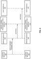
- Figure 5 illustrates matching of a digital signal processing logic module and a control module to an appropriate bridge module of a plurality of bridge modules to illustrate operation of the apparatus 100 in accordance with an embodiment of the present disclosure.
- the host module 120 may operate a plurality of bridge modules 500.
- Each of the bridge modules 500 may correspond to a particular digital signal processing logic module and a control module.
- a first bridge module e.g., bridge module-1
- a second bridge module e.g., bridge module-2
- the host module 120 may pass a set of arguments to the bridge module (e.g., the "original plug-in name").
- the bridge module may then, based on these arguments, look up the corresponding control module and digital signal processing logic module.
- a mapping may be retained, for example, in a file or in a registry, which the bridge module may consult to determine which control module and digital signal processing logic module to load.
- Figures 6-8 respectively illustrate an example block diagram 600, a flowchart of an example method 700, and a further example block diagram 800 for digital signal processing plug-in implementation, according to examples.
- the block diagram 600, the method 700, and the block diagram 800 may be implemented on the apparatus 100 described above with reference to Figure 1 by way of example and not of limitation.
- the block diagram 600, the method 700, and the block diagram 800 may be practiced in other apparatus.
- Figure 6 shows hardware of the apparatus 100 that may execute the instructions of the block diagram 600.
- the hardware may include a processor 602, and a memory 604 storing machine readable instructions that when executed by the processor cause the processor to perform the instructions of the block diagram 600.
- the memory 604 may represent a non-transitory computer readable medium.
- Figure 7 may represent an example method for digital signal processing plug-in implementation, and the steps of the method.
- Figure 8 may represent a non-transitory computer readable medium 802 having stored thereon machine readable instructions to provide digital signal processing plug-in implementation according to an example.
- the machine readable instructions when executed, cause a processor 804 to perform the instructions of the block diagram 800 also shown in Figure 8 .
- the processor 602 of Figure 6 and/or the processor 804 of Figure 8 may include a single or multiple processors or other hardware processing circuit, to execute the methods, functions and other processes described herein. These methods, functions and other processes may be embodied as machine readable instructions stored on a computer readable medium, which may be non-transitory (e.g., the non-transitory computer readable medium 802 of Figure 8 ), such as hardware storage devices (e.g., RAM (random access memory), ROM (read only memory), EPROM (erasable, programmable ROM), EEPROM (electrically erasable, programmable ROM), hard drives, and flash memory).
- the memory 604 may include a RAM, where the machine readable instructions and data for a processor may reside during runtime.
- the memory 604 may include instructions 606 to obtain attributes 104 of a user interface 106 for a digital signal processing plug-in.
- the processor 602 may fetch, decode, and execute the instructions 608 to obtain attributes 110 of digital signal processing logic 112 for the digital signal processing plug-in.
- the processor 602 may fetch, decode, and execute the instructions 610 to generate, based on the attributes 104 of the user interface 106 and the attributes 110 of the digital signal processing logic 112, a plug-in process 116 to control operation of the user interface 106 and the digital signal processing logic 112.
- the processor 602 may fetch, decode, and execute the instructions 612 to establish, based on the generated plug-in process 116, a two-way communication link 118 between a host module 120 and the plug-in process 116 to implement the digital signal processing plug-in.
- the method may include obtaining attributes 104 of a user interface 106 for a digital signal processing plug-in.
- the method may include obtaining attributes 110 of digital signal processing logic 112 for the digital signal processing plug-in.
- the method may include generating, based on the attributes 104 of the user interface 106 and the attributes 110 of the digital signal processing logic 112, a plug-in process 116 to control operation of the user interface 106 and the digital signal processing logic 112.
- the method may include establishing, based on the generated plug-in process 116 and via IPC APIs, a two-way communication link 118 between a host module 120 and the plug-in process 116 to implement the digital signal processing plug-in.
- the non-transitory computer readable medium 802 may include instructions 806 to obtain attributes 104 of a user interface 106 for a digital signal processing plug-in.
- the processor 804 may fetch, decode, and execute the instructions 808 to obtain attributes 110 of digital signal processing logic 112 for the digital signal processing plug-in.
- the processor 804 may fetch, decode, and execute the instructions 810 to generate, based on the attributes 104 of the user interface 106 and the attributes 110 of the digital signal processing logic 112, a plug-in process 116 to control operation of the user interface 106 and the digital signal processing logic 112.
- the processor 804 may fetch, decode, and execute the instructions 812 to establish, based on the generated plug-in process 116 and via IPC APIs, a two-way communication link 118 between a host module 120 and the plug-in process 116 to implement the digital signal processing plug-in by generating, for the IPC APIs, a memory-mapped file, and utilizing the memory-mapped file and a lock-free producer-consumer queue to establish the two-way communication link.
Landscapes
- Engineering & Computer Science (AREA)
- Theoretical Computer Science (AREA)
- Software Systems (AREA)
- Physics & Mathematics (AREA)
- Multimedia (AREA)
- General Engineering & Computer Science (AREA)
- General Physics & Mathematics (AREA)
- Acoustics & Sound (AREA)
- Computer Networks & Wireless Communication (AREA)
- Signal Processing (AREA)
- Health & Medical Sciences (AREA)
- Audiology, Speech & Language Pathology (AREA)
- General Health & Medical Sciences (AREA)
- Human Computer Interaction (AREA)
- Stored Programmes (AREA)
Description
- The invention relates to a digital signal processing plug-in implementation.
- A digital signal processing plug-in may represent computer software that may be used to modify an audio file, and/or generate and synthesize audio. For example, the digital signal processing plug-in may include a user interface that may be used to specify parameters that may be used to modify the audio file. Due to performance specifications and other such factors, digital signal processing plug-ins may be developed using specific computer languages. Moreover, computer code used to implement a digital signal processing plug-in may be specific to a platform type, such as macOS™, Windows™, Android™, etc. In this regard, it is technically challenging to utilize and develop a digital signal processing plug-in that is developed using a specific computer language and for a particular platform with different types of platforms.
-
WO 2010/054235 A2 relates to a system that executes a plug-in for a web browser. During operation, the system obtains the plug-in as a native code module and executes the native code module in a secure runtime environment. Next, the system enables communication between the native code module and the web browser by providing an interface bridge between the native code module and the web browser. - It is the object of the present invention to enable an improved implementation of a digital signal processing plug-in.
- The object is solved by the subject matter of the independent claims which define the present invention.
- Preferred embodiments of the invention are defined by the dependent claims.
- Features of the present disclosure are illustrated by way of example and not limited in the following figure(s), in which like numerals indicate like elements, in which:
-
Figure 1 illustrates a layout of a digital signal processing plug-in implementation apparatus in accordance with an embodiment of the present disclosure; -
Figure 2 illustrates loading of a bridge module by a host module, and loading of a digital signal processing logic module and a control module by the bridge module to illustrate operation of the digital signal processing plug-in implementation apparatus ofFigure 1 in accordance with an embodiment of the present disclosure; -
Figure 3 illustrates forwarding of musical instrument digital interface (MIDI) data from the host module to the bridge module, the digital signal processing logic module, and the control module of the digital signal processing plug-in implementation apparatus ofFigure 1 in accordance with an embodiment of the present disclosure; -
Figure 4 illustrates forwarding of parameter changes from the control module to the bridge module, the digital signal processing logic module, and the host module of the digital signal processing plug-in implementation apparatus ofFigure 1 in accordance with an embodiment of the present disclosure; -
Figure 5 illustrates matching of a digital signal processing logic module and a control module to an appropriate bridge module of a plurality of bridge modules to illustrate operation of the digital signal processing plug-in implementation apparatus ofFigure 1 in accordance with an embodiment of the present disclosure; -
Figure 6 illustrates an example block diagram for digital signal processing plug-in implementation in accordance with an embodiment of the present disclosure; -
Figure 7 illustrates a flowchart of an example method for digital signal processing plug-in implementation in accordance with an embodiment of the present disclosure; and -
Figure 8 illustrates a further example block diagram for digital signal processing plug-in implementation in accordance with another embodiment of the present disclosure. - For simplicity and illustrative purposes, the present disclosure is described by referring mainly to examples. In the following description, numerous specific details are set forth in order to provide a thorough understanding of the present disclosure. It will be readily apparent however, that the present disclosure may be practiced without limitation to these specific details. In other instances, some methods and structures have not been described in detail so as not to unnecessarily obscure the present disclosure.
- Throughout the present disclosure, the terms "a" and "an" are intended to denote at least one of a particular element. As used herein, the term "includes" means includes but not limited to, the term "including" means including but not limited to. The term "based on" means based at least in part on.
- Digital signal processing plug-in implementation apparatuses, methods for digital signal processing plug-in implementation, and non-transitory computer readable media having stored thereon machine readable instructions to provide digital signal processing plug-in implementation are disclosed herein. The apparatuses, methods, and non-transitory computer readable media disclosed herein may provide for implementation of a modular digital signal processing plug-in framework that includes a host module, a control module, a digital signal processing logic module, and a bridge module.
- As disclosed herein, due to performance specifications and other such factors, digital signal processing plug-ins may be developed using computer languages such as C, C++, etc. Moreover, computer code used to implement a digital signal processing plug-in may be specific to a platform type, such as macOS™, Windows™, Android™, etc. In this regard, it is technically challenging to utilize a digital signal processing plug-in that is developed using a specific computer language and for a particular platform with different types of platforms.
- In order to address at least the aforementioned technical challenges, the apparatuses, methods, and non-transitory computer readable media disclosed herein may provide for the implementation of a digital signal processing plug-in framework that includes a host module, a control module, a digital signal processing logic module, and a bridge module to operate as a proxy between the host module, the control module, and the digital signal processing logic module. The bridge module may be platform dependent, whereas the host module, the control module, and the digital signal processing logic module may be platform independent. Thus, the same host module, control module, and digital signal processing logic module may be used with a variety of platforms.
- According to examples disclosed herein, the bridge module may represent a thin layer which the host module interacts with. The host module may be tasked with loading the bridge module as disclosed herein. The digital signal processing logic module may be tasked with handling of audio-related digital signal processing logic, examples of which include logic for generating or synthesizing audio, or augmenting an existing audio stream. The control module may provide for the modification of parameters for the digital signal processing plug-in, which may be implemented by the host module, the control module, the digital signal processing logic module, and the bridge module. Further, the control module may provide a user interface for an end-user, where the end-user may utilize the user interface to control the digital signal processing logic module in real time. Examples of controlling the digital signal processing logic module may include controlling a "volume level" parameter, controlling "stereo image" parameters of generated and/or synthesized audio, etc. According to another example, with respect to filtering, examples of parameters may include "filter type", "filter threshold", etc.
- The bridge module may efficiently relay data in memory to different processes as disclosed herein. This functionality may provide for the usage of any programming language to write the actual digital signal processing logic and user interface experiences, which may thereafter be ported in a cross-platform manner. For example, the bridge module may be loaded by the host module. From the perspective of the host module, the bridge module may operate as a plug-in. In this regard, the host module may be unaware of the abstractions provided by the bridge module (such as the digital signal processing logic module, and the control module).
- The bridge module may be built for a specific host module to facilitate communication of the host module with the bridge module. In this regard, the bridge module may be built, for example, by using a host-specific software development kit (SDK) to export a host-specific set of application programming interfaces (APIs).
- With respect to operation of the apparatuses, methods, and non-transitory computer readable media disclosed herein, the host module may start by loading the bridge module, for example, as a dynamically linked library (DLL), for example, in Windows™ or a shared object library in Linux™ or Mac™ from a file system, using operating system loader APIs. For example, in Windows™, the host module may use the LoadLibrary API.
- The host module may then initialize the bridge module. As part of this initialization procedure, the host module may pass "configuration metadata" to the bridge module's initialization routine. The exact set of metadata may be implementation specific (e.g., depending on the specific host module and platform), but may include parameters such as "plugin name", "channel count", "bitrate" among others.
- The bridge module's initialization routine may be implemented as follows.
- First, the bridge module may accept configuration parameters from the host module.
- Next, the bridge module may establish an inter-process communication (IPC) mechanism which may be later used by the digital signal processing logic module and control module. An example of the IPC mechanism may include a named memory mapped file. The bridge module may start by calling, for example, CreateFileMapping and MapViewOfFile APIs on Windows™ (or similar APIs on other operating systems).
- A named memory-mapped file may represent an IPC mechanism that allows processes that may be executed in isolation, to communicate and exchange data with each other. In the case of memory-mapped files, an operating system may offer two (or more) processes to share memory in between each other.
- Next, the bridge module may initialize a shared lock-free producer-consumer queue on top of the memory mapped file. The exact layout of the shared lock-free producer-consumer queue may be implementation specific, but the initialization may include creating the shared lock-free producer-consumer queue and its internal structures in-memory.
- A lock free producer-consumer queue may represent the data structure/algorithm that is used on-top of the memory-mapped file to facilitate the communication. The lock free producer-consumer queue may establish a protocol for the different processes involved to communicate with one another efficiently. The lock free producer-consumer queue may support "ReadMessage" and "WriteMessage" APIs which may be utilized by the host module, the bridge module, the digital signal processing logic module, and the control module.
- Next, the bridge module may resolve which specific digital signal processing logic module and/or control module are to be used. The bridge module may do so, for example, by relying on the configuration parameters passed to it from the host module, in which case the bridge module may need to resolve a "plugin name" into a set of "digital signal processing logic module and control module". In this regard, the bridge module may consult a mapping of this data, for example, by parsing a file on the file system, or by reading from a registry (e.g., the Windows™ registry). In some cases, the mapping may be embedded directly into the bridge module (e.g., by hardcoding).
- Once the digital signal processing logic module and the control module resolution has been completed, the bridge module may load the digital signal processing logic module and the control module. This loading may include the creation of a separate process for the digital signal processing logic module and the control module modules (e.g., by using a CreateProcess API in Windows™).
- Since the digital signal processing logic module and the control module now exist in a separate process, this feature may decouple any technology and/or programming language needed to build these modules from any technologies and/or programming languages used by the bridge module and the host module. In other words, the digital signal processing logic module and the control module may be written in any desired programming language and/or technology.
- Once the digital signal processing logic module and the control module are loaded, the bridge module's initialization routine may be considered completed, and control may be relinquished back to the host module (as well as the digital signal processing logic module and the control module). From this point on, the bridge module may serve as a relaying mechanism for data to pass back-and-forth between the host module and the digital signal processing logic module and the control module.
- Once the bridge module has been fully loaded, the host module may communicate with the bridge module in the following manner.
- Asynchronously, the host module may send a MIDI message to the bridge module. In this regard, the host module may call a function exported by the bridge module. The bridge module may take the MIDI message and forward the MIDI message using the shared lock-free producer-consumer queue to the digital signal processing logic module and the control module.
- According to another example, the host module may routinely call the bridge module to determine whether audio data has been made available to the bridge module (e.g., by "polling" the bridge module in a loop). For example, the host module may call a function exported by the bridge module. The bridge module may determine whether audio data is available in the shared lock-free producer-consumer queue, read the audio data, and return the audio data back to the host module.
- According to examples disclosed herein, the apparatuses, methods, and non-transitory computer readable media disclosed herein provide for control of the digital signal processing plugin remotely over a network, or through a mobile device.
- According to examples disclosed herein, the bridge module for the apparatuses, methods, and non-transitory computer readable media disclosed herein may pass data between the digital signal processing logic module, the control module, and the host module over in-memory inter-process communication. In this regard, the bridge module may establish an IPC communications channel, and utilize this channel to pass data (e.g., messages) across different components of the apparatuses as disclosed herein. According to an example, the IPC communication channel may be implemented by using a memory-mapped file (e.g., APIs) as disclosed herein. The memory-mapped file may provide for the seamless sharing of memory across different components of the apparatuses as disclosed herein, where such components may otherwise operate in an independent (e.g., isolated) manner.
- According to examples disclosed herein, the bridge module for the apparatuses, methods, and non-transitory computer readable media disclosed herein may pass data between the digital signal processing logic module, the control module, and the host module over a network.
- According to examples disclosed herein, certain functionality of the digital signal processing logic module and the control module may be implemented in a browser, or as part of a web-browser based system. Based on the implementation of the digital signal processing logic module and the control module in a browser, or as part of a web-browser based system, these modules may be operated, for example, via a mobile device, such as a mobile phone, a tablet, etc. Yet further, based on the implementation of the digital signal processing logic module and the control module in a browser, or as part of a web-browser based system, these modules may be operated by one or simultaneously by a plurality of users.
- For the apparatuses, methods, and non-transitory computer readable media disclosed herein, modules, as described herein, may be any combination of hardware and programming to implement the functionalities of the respective modules. In some examples described herein, the combinations of hardware and programming may be implemented in a number of different ways. For example, the programming for the modules may be processor executable instructions stored on a non-transitory machine-readable storage medium and the hardware for the modules may include a processing resource to execute those instructions. In these examples, a computing device implementing such modules may include the machine-readable storage medium storing the instructions and the processing resource to execute the instructions, or the machine-readable storage medium may be separately stored and accessible by the computing device and the processing resource. In some examples, some modules may be implemented in circuitry.
-
Figure 1 illustrates a layout of an example digital signal processing plug-in implementation apparatus (hereinafter also referred to as "apparatus 100"). - Referring to
Figure 1 , theapparatus 100 may include a bridge module 102 (hereinafter also referred to as "bridge") to obtainattributes 104 of a user interface 106 for a digital signal processing plug-in. In this regard, the digital signal processing plug-in may be implemented by theapparatus 100. Further, the user interface 106 may be implemented by a control module 108 (hereinafter also referred to as "controller"). Examples ofattributes 104 may include a programming language that is used to implement the user interface 106, a platform that the user interface 106 is implemented for, etc. - The
bridge module 102 may obtainattributes 110 of digital signal processing logic 112 for the digital signal processing plug-in. The digital signal processing logic 112 may be implemented by a digital signalprocessing logic module 114. Examples ofattributes 110 may include a programming language that is used to implement the digital signal processing logic 112, a platform that the digital signal processing logic 112 is implemented for, etc. - The
bridge module 102 may generate, based on theattributes 104 of the user interface 106 and theattributes 110 of the digital signal processing logic 112, a plug-inprocess 116 to control operation of the user interface 106 and the digital signal processing logic 112. - The
bridge module 102 may establish, based on the generated plug-inprocess 116, a two-way communication link 118 between a host module 120 (hereinafter also referred to as "host") and the plug-inprocess 116 to implement the digital signal processing plug-in. - According to examples disclosed herein, the
bridge module 102 may establish, based on the generated plug-in process and via IPC APIs, the two-way communication link 118 between thehost module 120 and the plug-inprocess 116 to implement the digital signal processing plug-in. - According to examples disclosed herein, the
bridge module 102 may generate, for the IPC APIs, a memory-mapped file. Further, thebridge module 102 may utilize the memory-mapped file and a lock-free producer-consumer queue to establish the two-way communication link 118. - According to examples disclosed herein, the
bridge module 102 may forward musical instrument digital interface (MIDI) data to the lock-free producer-consumer queue. - According to examples disclosed herein, the
bridge module 102 may receive audio data from the lock-free producer-consumer queue. - According to examples disclosed herein, the
bridge module 102 may obtain, from thehost module 120, MIDI data to be processed by the plug-inprocess 116. Thebridge module 102 may forward, via the two-way communication link 118, the MIDI data to the plug-inprocess 116. - According to examples disclosed herein, the
bridge module 102 may obtain, from the plug-inprocess 116, audio data. Further, thebridge module 102 may forward, via the two-way communication link 118, the audio data to thehost module 120. - Operation of the
apparatus 100 is described in further detail with reference toFigures 1-5 . - As disclosed herein, the
bridge module 102 may generate, based on theattributes 104 of the user interface 106 and theattributes 110 of the digital signal processing logic 112, a plug-inprocess 116 to control operation of the user interface 106 and the digital signal processing logic 112. In this regard, thehost module 120, which may be designated as Process-1, may load thebridge module 102 in memory. During the loading procedure, thebridge module 102 may create the plug-in process 116 (which may also be designated as Process-2). For example, the plug-inprocess 116 may include a locally running web server which will host the user interface 106 for the digital signal processing plugin, as-well as the digital signal processing logic 112. - The
host module 120 may further establish the two-way communication link 118 with the plug-in process 116 (and thus with the digital signalprocessing logic module 114 and the control module 108) via IPC APIs. For example, the two-way communication link 118 may be generated by creating a memory-mapped file, over which the two processes (e.g., Process-1 and Process-2 (the plug-in process 116)) may communicate by means of a lock-free producer-consumer queue(s). An example of IPC APIs may include CreateFileMapping (INVALID HANDLE VALUE, NULL, PAGE READWRITE, 0, QUEUE_SIZE_BYTES, NAME), MapViewOfFile (hFileMapping, FILE MAPALL ACCESS, 0, 0, QUEUE_SIZE_BYTES). In this regard, the IPC APIs may establish the two-way communication link 118 for the aforementioned processes. The lock-free producer-consumer queue may reside on top of the memory-mapped file, and serve as the protocol for passing data back and forth between the different processes (and thus between thehost module 120, the digital signalprocessing logic module 114, and the control module 108). - MIDI data originating from the host module 120 (e.g., Process-1) may be sent to the
bridge module 102, which may further forward the MIDI data to Process-2 (the plug-in process 116) via the established two-way communication link 118 and the MIDI data may be read and processed by Process-2 (the plug-in process 116). - Audio data originating from the Process-2 (the plug-in process 116) may be sent back to the
bridge module 102 via the established two-way communication link 118, and finally back to thehost module 120. - A user may graphically control and observe the behavior of the
apparatus 100, for example, by using a web-browser. In this regard, the web browser may communicate over HyperText Transfer Protocol (HTTP) with Process-2 (the plug-in process 116). The web browser may serve as a presentation layer, for example, to display the user interface 106 for a user. According to an example, thecontrol module 108 may serve the associated web-page for the user via HTTP. - An example of a flow related to operation of the
host module 120 may include loading of a plugin routine to implement the digital signal processing plug-in by loading of thebridge module 102. Loading of thebridge module 102 may initiate a host specific initialization routine to create the plug-inprocess 116. As disclosed herein, the two-way communication link 118 may be established by creation of a named memory mapped file, and initialization of a lock-free producer-consumer queue. With respect to handling of MIDI messages from the bridge module, MIDI messages may be sent to the lock-free producer-consumer queue. The MIDI messages may flow in both directions (e.g., to/from) thehost module 120, the digital signalprocessing logic module 114, and thecontrol module 108, with the lock-free producer-consumer queue being the medium which delivers these messages in either direction. An example may include thehost module 120 sending a MIDI message to the bridge module 102 (and the digital signal processing logic module 114), the payload being a MIDI instruction to "play a specific note". - With respect to handling of audio data, audio data may be read from the lock-free producer-consumer queue. The audio data may be sent to and from the digital signal
processing logic module 114. For example, audio data originating from the digital signal processing logic module 114 (e.g., synthesized audio) may be sent back to thehost module 120 via thebridge module 102 for further processing by thehost module 120. Audio data originating from thehost module 120 may be sent to the digital signalprocessing logic module 114 for further processing (e.g., taking a pre-existing audio stream, and making it louder). - A flow related to a secondary process includes loading of a plugin routine to implement the digital signal processing plug-in by establishing the two-way communication link 118 with the
bridge module 102. Thereafter, a named memory mapped file is created, and attached to the shared lock-free producer-consumer queue. - As disclosed herein, the named memory-mapped file represents an IPC mechanism that allows processes that may be executed in isolation, to communicate and exchange data with each other. In the case of memory-mapped files, an operating system may offer two (or more) processes to share memory in between each other.
- As disclosed herein, the lock free producer-consumer queue may represent the data structure/algorithm that is used on-top of the memory-mapped file to facilitate the communication. The lock free producer-consumer queue may establish a protocol for the different processes involved to communicate with one another efficiently. The lock free producer-consumer queue may support "ReadMessage" and "WriteMessage" APIs which may be utilized by the
host module 120, thebridge module 102, the digital signalprocessing logic module 114, and thecontrol module 108. - The
host module 120 may send a MIDI message to thebridge module 102. Thebridge module 102 may send the MIDI message using, for example, the "WriteMessage" API. The digital signalprocessing logic module 114 and thecontrol module 108 may then pick up the MIDI message using, for example, the "ReadMessage" API and react on the message. Audio data may be handled in a similar manner. - With respect to handling of MIDI messages (e.g., host-specific), the user interface 106 may be updated as needed. In this regard, the
host module 120 may instruct thebridge module 102 to "play a certain note" by passing a corresponding MIDI message. Thebridge module 102 may then relay this message to both the digital signalprocessing logic module 114 and thecontrol module 108. Thecontrol module 108 may then decide to, for example, display some type of user interface animation that corresponds with "playing a certain note". - Based on the update to the user interface 106, digital signal processing logic 112 may be applied as needed. With respect to audio handling, audio data may be generated based on a plug-in specific logic. In a similar manner as the MIDI data, depending on the product that is being developed, the digital signal
processing logic module 114 may differ for each product. For example, a type of the digital signalprocessing logic module 114 may generate certain types of sounds (e.g., some type of synthesizer). When the sound is "generated", the sound may be sent back to thehost module 120. Thehost module 120 may then route the sound, for example, to the computer's audio interface so that it can be played over the speakers. This audio may be first generated by the digital signalprocessing logic module 114, and may then travel all the way back to thebridge module 102 and thehost module 120. In this regard, the lock-free producer-consumer queue may represent the "message bus" that lets the digital signalprocessing logic module 114 send the data efficiently back to thebridge module 102. -
Figure 2 illustrates loading of thebridge module 102 by thehost module 120, and loading of the digital signalprocessing logic module 114 and thecontrol module 108 by thebridge module 102 to illustrate operation of theapparatus 100 in accordance with an embodiment of the present disclosure. - Referring to
Figure 2 , as disclosed above, thehost module 120 may be tasked with loading of thebridge module 102. For example, as disclosed above, operation of thehost module 120 may include loading of a plugin routine to implement the digital signal processing plug-in by loading of thebridge module 102. Further, as disclosed above, an example of a flow related to a secondary process may include loading of a plugin routine to implement the digital signal processing plug-in by establishing the two-way communication link 118 with thebridge module 102. In this regard, once the two-way communication link 118 is established, thebridge module 102 may load the digital signalprocessing logic module 114 and thecontrol module 108. - As disclosed herein, the
host module 120 may start by loading thebridge module 102. - The
host module 120 may initialize thebridge module 102. The exact initialization protocol may be both host and platform specific (e.g., thebridge module 102 may be developed to abstract these aspects away from the actual digital signalprocessing logic module 114 and the control module 108). As part of the initialization procedure, thehost module 120 may provide thebridge module 102 with a runtime "configuration". The configuration data may include, for example, a "Plugin Name" string. - When the
bridge module 102 is initializing upon first being loaded by thehost module 120, thebridge module 102 may need to load and initialize the digital signalprocessing logic module 114 and thecontrol module 108. For example, thebridge module 102 may consult a "mapping" of the "Plugin Name" string, to locate the digital signalprocessing logic module 114 and thecontrol module 108. The mapping may likely come in the form of a file, or a global registry (such as the Windows™ registry), or may be embedded within thebridge module 102. - Once the
bridge module 102 has established which specific digital signalprocessing logic module 114 andcontrol module 108 to load, thebridge module 102 may proceed to load the modules. This may include creating a new, separate process for thecontrol module 108 and the digital signalprocessing logic module 114. For example, for a control module and digital signal processing logic module written in Python, thebridge module 102 may run the "python.exe" interpreter process, which may execute thecontrol module 108 and the digital signalprocessing logic module 114 codes. - The two-way communication link 118 may be a communication link between the
bridge module 102, the digital signalprocessing logic module 114, and thecontrol module 108. -
Figure 3 illustrates forwarding of MIDI data from thehost module 120 to thebridge module 102, the digital signal processing logic 112, and thecontrol module 108 of theapparatus 100 in accordance with an embodiment of the present disclosure. - Referring to
Figure 3 , with respect toMIDI messages 300 that are to be transferred from thehost module 120 to the digital signalprocessing logic module 114 and thecontrol module 108, such MIDI messages may be received by thebridge module 102 and transferred from thebridge module 102 to the digital signalprocessing logic module 114 and thecontrol module 108. In this regard, if a MIDI message is received from the host module, the MIDI message may be sent to the digital signalprocessing logic module 114 and thecontrol module 108 via the shared lock-free producer-consumer queue, and vice-versa. The shared lock-free producer-consumer queue may operate as a message bus to provide read message and write message capabilities. An example of a MIDI message may include a user playing a key on a keyboard. In this regard, the MIDI message may be sent from thehost module 120 to thebridge module 102. Thebridge module 102 may pass the MIDI message to the digital signalprocessing logic module 114 to play a sound associated with the MIDI message, and to thecontrol module 108 to display musical notes associated with the MIDI message. -
Figure 4 illustrates forwarding of parameter changes from thecontrol module 108 to thebridge module 102, the digital signalprocessing logic module 114, and thehost module 120 of theapparatus 100 in accordance with an embodiment of the present disclosure. - Referring to
Figure 4 , with respect to parameters that are changed at thecontrol module 108, such parameter changes may be transferred to thebridge module 102, which may further notify the digital signalprocessing logic module 114 and thehost module 120 of the parameter changes. An example of a parameter change includes "a user toggles a graphical fader, which corresponds with the output level parameter in the digital signalprocessing logic module 114." The notification from thebridge module 102 to the digital signalprocessing logic module 114 may include an indication of what needs to be done differently based on the parameter changes. Further, the notification from thebridge module 102 to thehost module 120 may include an indication of a parameter change request. -
Figure 5 illustrates matching of a digital signal processing logic module and a control module to an appropriate bridge module of a plurality of bridge modules to illustrate operation of theapparatus 100 in accordance with an embodiment of the present disclosure. - Referring to
Figure 5 , thehost module 120 may operate a plurality ofbridge modules 500. Each of thebridge modules 500 may correspond to a particular digital signal processing logic module and a control module. For example, a first bridge module (e.g., bridge module-1) may correspond to a particular digital signal processing logic module-1 and a control module-1 for an IOS™ system at 502, a second bridge module (e.g., bridge module-2) may correspond to another particular digital signal processing logic module-2 and control module-2 for an Android™ system at 504, etc. Thehost module 120 may pass a set of arguments to the bridge module (e.g., the "original plug-in name"). The bridge module may then, based on these arguments, look up the corresponding control module and digital signal processing logic module. A mapping may be retained, for example, in a file or in a registry, which the bridge module may consult to determine which control module and digital signal processing logic module to load. -
Figures 6-8 respectively illustrate an example block diagram 600, a flowchart of anexample method 700, and a further example block diagram 800 for digital signal processing plug-in implementation, according to examples. The block diagram 600, themethod 700, and the block diagram 800 may be implemented on theapparatus 100 described above with reference toFigure 1 by way of example and not of limitation. The block diagram 600, themethod 700, and the block diagram 800 may be practiced in other apparatus. In addition to showing the block diagram 600,Figure 6 shows hardware of theapparatus 100 that may execute the instructions of the block diagram 600. The hardware may include aprocessor 602, and amemory 604 storing machine readable instructions that when executed by the processor cause the processor to perform the instructions of the block diagram 600. Thememory 604 may represent a non-transitory computer readable medium.Figure 7 may represent an example method for digital signal processing plug-in implementation, and the steps of the method.Figure 8 may represent a non-transitory computerreadable medium 802 having stored thereon machine readable instructions to provide digital signal processing plug-in implementation according to an example. The machine readable instructions, when executed, cause aprocessor 804 to perform the instructions of the block diagram 800 also shown inFigure 8 . - The
processor 602 ofFigure 6 and/or theprocessor 804 ofFigure 8 may include a single or multiple processors or other hardware processing circuit, to execute the methods, functions and other processes described herein. These methods, functions and other processes may be embodied as machine readable instructions stored on a computer readable medium, which may be non-transitory (e.g., the non-transitory computerreadable medium 802 ofFigure 8 ), such as hardware storage devices (e.g., RAM (random access memory), ROM (read only memory), EPROM (erasable, programmable ROM), EEPROM (electrically erasable, programmable ROM), hard drives, and flash memory). Thememory 604 may include a RAM, where the machine readable instructions and data for a processor may reside during runtime. - Referring to
Figures 1-6 , and particularly to the block diagram 600 shown inFigure 6 , thememory 604 may includeinstructions 606 to obtainattributes 104 of a user interface 106 for a digital signal processing plug-in. - The
processor 602 may fetch, decode, and execute theinstructions 608 to obtainattributes 110 of digital signal processing logic 112 for the digital signal processing plug-in. - The
processor 602 may fetch, decode, and execute theinstructions 610 to generate, based on theattributes 104 of the user interface 106 and theattributes 110 of the digital signal processing logic 112, a plug-inprocess 116 to control operation of the user interface 106 and the digital signal processing logic 112. - The
processor 602 may fetch, decode, and execute theinstructions 612 to establish, based on the generated plug-inprocess 116, a two-way communication link 118 between ahost module 120 and the plug-inprocess 116 to implement the digital signal processing plug-in. - Referring to
Figures 1-5 and7 , and particularlyFigure 7 , for themethod 700, atblock 702, the method may include obtainingattributes 104 of a user interface 106 for a digital signal processing plug-in. - At
block 704, the method may include obtainingattributes 110 of digital signal processing logic 112 for the digital signal processing plug-in. - At block 707, the method may include generating, based on the
attributes 104 of the user interface 106 and theattributes 110 of the digital signal processing logic 112, a plug-inprocess 116 to control operation of the user interface 106 and the digital signal processing logic 112. - At
block 708, the method may include establishing, based on the generated plug-inprocess 116 and via IPC APIs, a two-way communication link 118 between ahost module 120 and the plug-inprocess 116 to implement the digital signal processing plug-in. - Referring to
Figures 1-5 and8 , and particularlyFigure 8 , for the block diagram 800, the non-transitory computerreadable medium 802 may includeinstructions 806 to obtainattributes 104 of a user interface 106 for a digital signal processing plug-in. - The
processor 804 may fetch, decode, and execute theinstructions 808 to obtainattributes 110 of digital signal processing logic 112 for the digital signal processing plug-in. - The
processor 804 may fetch, decode, and execute theinstructions 810 to generate, based on theattributes 104 of the user interface 106 and theattributes 110 of the digital signal processing logic 112, a plug-inprocess 116 to control operation of the user interface 106 and the digital signal processing logic 112. - The
processor 804 may fetch, decode, and execute theinstructions 812 to establish, based on the generated plug-inprocess 116 and via IPC APIs, a two-way communication link 118 between ahost module 120 and the plug-inprocess 116 to implement the digital signal processing plug-in by generating, for the IPC APIs, a memory-mapped file, and utilizing the memory-mapped file and a lock-free producer-consumer queue to establish the two-way communication link.
Claims (14)
- An apparatus comprising:a processor; anda memory storing machine readable instructions that when executed by the processor cause the processor to:obtain attributes of a user interface for a digital signal processing plug-in;obtain attributes of digital signal processing logic for the digital signal processing plug-in;generate, based on the attributes of the user interface and the attributes of the digital signal processing logic, a plug-in process to control operation of the user interface and the digital signal processing logic; andestablish, based on the generated plug-in process, and via inter-process communication, IPC, application programming interfaces, APIs, a two-way communication link between a host and the plug-in process to implement the digital signal processing plug-in by generating for the IPC APIs, a memory-mapped file, and utilizing the memory-mapped file attached to a lock-free producer-consumer queue to establish the two-way communication link.
- The apparatus according to claim 1, wherein the instructions to establish, based on the generated plug-in process, the two-way communication link between the host and the plug-in process to implement the digital signal processing plug-in are further to cause the processor to:
establish, based on the generated plug-in process and via inter-process communication, IPC, application programming interfaces, APIs, the two-way communication link between the host and the plug-in process to implement the digital signal processing plug-in. - The apparatus according to claim 2, wherein the instructions to establish, based on the generated plug-in process and via the IPC APIs, the two-way communication link between the host and the plug-in process to implement the digital signal processing plug-in are further to cause the processor to:generate, for the IPC APIs, the memory-mapped file; andutilize the memory-mapped file and the lock-free producer-consumer queue to establish the two-way communication link.
- The apparatus according to claim 3, wherein the instructions are further to cause the processor to:
forward musical instrument digital interface, MIDI, data to the lock-free producer-consumer queue. - The apparatus according to claim 3, wherein the instructions are further to cause the processor to:
receive audio data from the lock-free producer-consumer queue. - The apparatus according to claim 1, wherein the instructions are further to cause the processor to:obtain, from the host, musical instrument digital interface (MIDI) data to be processed by the plug-in process; andforward, via the two-way communication link, the MIDI data to the plug-in process.
- The apparatus according to claim 1, wherein the instructions are further to cause the processor to:obtain, from the plug-in process, audio data; andforward, via the two-way communication link, the audio data to the host.
- The apparatus according to claim 1, wherein the instructions are further to cause the processor to:receive configuration metadata from the host; andidentify, based on the configuration metadata, the user interface of a plurality of user interfaces and the digital signal processing logic of a plurality of digital signal processing logics for implementing communication with the host.
- A computer-implemented method comprising:obtaining attributes of a user interface for a digital signal processing plug-in;obtaining attributes of digital signal processing logic for the digital signal processing plug-in;generating, based on the attributes of the user interface and the attributes of the digital signal processing logic, a plug-in process to control operation of the user interface and the digital signal processing logic; andestablishing, based on the generated plug-in process and via inter-process communication, IPC, application programming interfaces, APIs, a two-way communication link between a host and the plug-in process to implement the digital signal processing plug-in bygenerating, for the IPC APIs, a memory-mapped file, andutilizing the memory-mapped file attached to a lock-free producer-consumer queue to establish the two-way communication link.
- The computer-implemented method according to claim 9, further comprising:
forwarding musical instrument digital interface, MIDI, data to the lock-free producer-consumer queue. - The computer-implemented method according to claim 9, further comprising:
receiving audio data from the lock-free producer-consumer queue. - The computer-implemented method according to claim 9, further comprising:obtaining, from the host, musical instrument digital interface, MIDI, data to be processed by the plug-in process; andforwarding, via the two-way communication link, the MIDI data to the plug-in process.
- The computer-implemented method according to claim 9, further comprising:obtaining, from the plug-in process, audio data; andforwarding, via the two-way communication link, the audio data to the host.
- A computer readable medium having stored thereon machine readable instructions, the machine readable instructions, when executed by a processor, cause the processor to perform a method according to one of claims 9 to 13.
Applications Claiming Priority (2)
| Application Number | Priority Date | Filing Date | Title |
|---|---|---|---|
| US16/505,067 US10983842B2 (en) | 2019-07-08 | 2019-07-08 | Digital signal processing plug-in implementation |
| PCT/US2020/032549 WO2021006947A1 (en) | 2019-07-08 | 2020-05-12 | Digital signal processing plug-in implementation |
Publications (2)
| Publication Number | Publication Date |
|---|---|
| EP3997567A1 EP3997567A1 (en) | 2022-05-18 |
| EP3997567B1 true EP3997567B1 (en) | 2023-12-20 |
Family
ID=70919189
Family Applications (1)
| Application Number | Title | Priority Date | Filing Date |
|---|---|---|---|
| EP20729500.7A Active EP3997567B1 (en) | 2019-07-08 | 2020-05-12 | Digital signal processing plug-in implementation |
Country Status (3)
| Country | Link |
|---|---|
| US (2) | US10983842B2 (en) |
| EP (1) | EP3997567B1 (en) |
| WO (1) | WO2021006947A1 (en) |
Families Citing this family (1)
| Publication number | Priority date | Publication date | Assignee | Title |
|---|---|---|---|---|
| WO2023121656A1 (en) * | 2021-12-21 | 2023-06-29 | Futurewei Technologies, Inc. | Parallel processing using a memory-based communication mechanism |
Family Cites Families (13)
| Publication number | Priority date | Publication date | Assignee | Title |
|---|---|---|---|---|
| JPH07504054A (en) * | 1992-02-18 | 1995-04-27 | アプル・コンピュータ・インコーポレーテッド | Programming model for coprocessors in computer systems |
| US8489860B1 (en) * | 1997-12-22 | 2013-07-16 | Texas Instruments Incorporated | Mobile electronic device having a host processor system capable of dynamically canging tasks performed by a coprocessor in the device |
| US7080386B2 (en) * | 2000-01-25 | 2006-07-18 | Texas Instruments Incorporated | Architecture with digital signal processor plug-ins for general purpose processor media frameworks |
| US7162426B1 (en) | 2000-10-02 | 2007-01-09 | Xybernaut Corporation | Computer motherboard architecture with integrated DSP for continuous and command and control speech processing |
| US20020065568A1 (en) | 2000-11-30 | 2002-05-30 | Silfvast Robert Denton | Plug-in modules for digital signal processor functionalities |
| US6996832B2 (en) | 2001-05-30 | 2006-02-07 | Bea Systems, Inc. | System and method for software component plug-in framework |
| US20030167345A1 (en) | 2002-02-25 | 2003-09-04 | Knight Alexander N. | Communications bridge between a vehicle information network and a remote system |
| US7441020B2 (en) | 2003-06-27 | 2008-10-21 | Microsoft Corporation | Media plug-in registration and dynamic loading |
| JP2005317115A (en) | 2004-04-28 | 2005-11-10 | Sony Corp | Information processing apparatus, information processing method, and program |
| US20060122814A1 (en) | 2004-12-03 | 2006-06-08 | Beens Jason A | Method and apparatus for digital signal processing analysis and development |
| US7663046B2 (en) | 2007-03-22 | 2010-02-16 | Qualcomm Incorporated | Pipeline techniques for processing musical instrument digital interface (MIDI) files |
| US8352967B2 (en) | 2008-11-10 | 2013-01-08 | Google Inc. | Safe browser plugins using native code modules |
| CN204143202U (en) | 2014-10-24 | 2015-02-04 | 南京南瑞继保工程技术有限公司 | A kind of integrated measure and control device |
-
2019
- 2019-07-08 US US16/505,067 patent/US10983842B2/en active Active
-
2020
- 2020-05-12 WO PCT/US2020/032549 patent/WO2021006947A1/en not_active Ceased
- 2020-05-12 EP EP20729500.7A patent/EP3997567B1/en active Active
-
2021
- 2021-03-12 US US17/200,432 patent/US11500695B2/en active Active
Also Published As
| Publication number | Publication date |
|---|---|
| WO2021006947A1 (en) | 2021-01-14 |
| US20210011784A1 (en) | 2021-01-14 |
| US11500695B2 (en) | 2022-11-15 |
| US20210200606A1 (en) | 2021-07-01 |
| EP3997567A1 (en) | 2022-05-18 |
| US10983842B2 (en) | 2021-04-20 |
Similar Documents
| Publication | Publication Date | Title |
|---|---|---|
| KR102414096B1 (en) | Create and deploy packages for machine learning on end devices | |
| US12159155B1 (en) | Edge computing system | |
| US11829787B2 (en) | Multi-process model for cross-platform applications | |
| CN113986515B (en) | Method and device for creating sandbox environment for plug-in operation and computing equipment | |
| EP4002121B1 (en) | Middleware interface and middleware interface generator | |
| US20130263160A1 (en) | Cross-platform web-based native device feature access | |
| CN113168332A (en) | Data processing method and device and mobile terminal | |
| AU2019256257A1 (en) | Processor core scheduling method and apparatus, terminal, and storage medium | |
| GB2483167A (en) | Storage device with separate application and interface processors | |
| CN105843668A (en) | Derived process staying-resident method, derived program generating method and corresponding device | |
| CN105740027B (en) | Application update method and device | |
| US6754819B1 (en) | Method and system for providing cryptographic services in a distributed application | |
| JP4943650B2 (en) | System for multimedia rendering on portable devices | |
| WO2021239073A1 (en) | Method for constructing internet of things operating system, system, cloud platform and internet of things device | |
| US8489860B1 (en) | Mobile electronic device having a host processor system capable of dynamically canging tasks performed by a coprocessor in the device | |
| US20170177395A1 (en) | Embedded architecture based on process virtual machine | |
| US11500695B2 (en) | Digital signal processing plug-in implementation | |
| CN115174687A (en) | Service calling method and device, electronic equipment and storage medium | |
| CN118733304A (en) | Socket communication method and system for implementing local TCP using shared memory | |
| CN116700694B (en) | Applet engine | |
| CN115080226B (en) | Method, device, electronic device and storage medium for executing service | |
| CN115766609B (en) | Communication method and system of lua script and engine, electronic equipment and storage medium | |
| CN121635984A (en) | System capability loading methods and electronic devices | |
| CN119213865A (en) | Accelerating the deployment of abstraction layers in cellular communication systems | |
| KR101721379B1 (en) | Method and system for efficient call processing |
Legal Events
| Date | Code | Title | Description |
|---|---|---|---|
| STAA | Information on the status of an ep patent application or granted ep patent |
Free format text: STATUS: UNKNOWN |
|
| STAA | Information on the status of an ep patent application or granted ep patent |
Free format text: STATUS: THE INTERNATIONAL PUBLICATION HAS BEEN MADE |
|
| PUAI | Public reference made under article 153(3) epc to a published international application that has entered the european phase |
Free format text: ORIGINAL CODE: 0009012 |
|
| STAA | Information on the status of an ep patent application or granted ep patent |
Free format text: STATUS: REQUEST FOR EXAMINATION WAS MADE |
|
| 17P | Request for examination filed |
Effective date: 20211209 |
|
| AK | Designated contracting states |
Kind code of ref document: A1 Designated state(s): AL AT BE BG CH CY CZ DE DK EE ES FI FR GB GR HR HU IE IS IT LI LT LU LV MC MK MT NL NO PL PT RO RS SE SI SK SM TR |
|
| DAV | Request for validation of the european patent (deleted) | ||
| DAX | Request for extension of the european patent (deleted) | ||
| GRAP | Despatch of communication of intention to grant a patent |
Free format text: ORIGINAL CODE: EPIDOSNIGR1 |
|
| STAA | Information on the status of an ep patent application or granted ep patent |
Free format text: STATUS: GRANT OF PATENT IS INTENDED |
|
| RIC1 | Information provided on ipc code assigned before grant |
Ipc: G06F 9/451 20180101ALN20230629BHEP Ipc: H04L 65/75 20220101ALI20230629BHEP Ipc: H04L 65/61 20220101ALI20230629BHEP Ipc: G10H 1/00 20060101ALI20230629BHEP Ipc: G06F 3/16 20060101ALI20230629BHEP Ipc: G06F 9/54 20060101ALI20230629BHEP Ipc: G06F 9/445 20180101AFI20230629BHEP |
|
| RIC1 | Information provided on ipc code assigned before grant |
Ipc: G06F 9/451 20180101ALN20230703BHEP Ipc: H04L 65/75 20220101ALI20230703BHEP Ipc: H04L 65/61 20220101ALI20230703BHEP Ipc: G10H 1/00 20060101ALI20230703BHEP Ipc: G06F 3/16 20060101ALI20230703BHEP Ipc: G06F 9/54 20060101ALI20230703BHEP Ipc: G06F 9/445 20180101AFI20230703BHEP |
|
| INTG | Intention to grant announced |
Effective date: 20230721 |
|
| GRAS | Grant fee paid |
Free format text: ORIGINAL CODE: EPIDOSNIGR3 |
|
| GRAA | (expected) grant |
Free format text: ORIGINAL CODE: 0009210 |
|
| STAA | Information on the status of an ep patent application or granted ep patent |
Free format text: STATUS: THE PATENT HAS BEEN GRANTED |
|
| AK | Designated contracting states |
Kind code of ref document: B1 Designated state(s): AL AT BE BG CH CY CZ DE DK EE ES FI FR GB GR HR HU IE IS IT LI LT LU LV MC MK MT NL NO PL PT RO RS SE SI SK SM TR |
|
| P01 | Opt-out of the competence of the unified patent court (upc) registered |
Effective date: 20231113 |
|
| REG | Reference to a national code |
Ref country code: GB Ref legal event code: FG4D |
|
| REG | Reference to a national code |
Ref country code: CH Ref legal event code: EP |
|
| REG | Reference to a national code |
Ref country code: DE Ref legal event code: R096 Ref document number: 602020023075 Country of ref document: DE |
|
| REG | Reference to a national code |
Ref country code: IE Ref legal event code: FG4D |
|
| PG25 | Lapsed in a contracting state [announced via postgrant information from national office to epo] |
Ref country code: GR Free format text: LAPSE BECAUSE OF FAILURE TO SUBMIT A TRANSLATION OF THE DESCRIPTION OR TO PAY THE FEE WITHIN THE PRESCRIBED TIME-LIMIT Effective date: 20240321 |
|
| REG | Reference to a national code |
Ref country code: LT Ref legal event code: MG9D |
|
| PG25 | Lapsed in a contracting state [announced via postgrant information from national office to epo] |
Ref country code: LT Free format text: LAPSE BECAUSE OF FAILURE TO SUBMIT A TRANSLATION OF THE DESCRIPTION OR TO PAY THE FEE WITHIN THE PRESCRIBED TIME-LIMIT Effective date: 20231220 |
|
| REG | Reference to a national code |
Ref country code: NL Ref legal event code: MP Effective date: 20231220 |
|
| PG25 | Lapsed in a contracting state [announced via postgrant information from national office to epo] |
Ref country code: ES Free format text: LAPSE BECAUSE OF FAILURE TO SUBMIT A TRANSLATION OF THE DESCRIPTION OR TO PAY THE FEE WITHIN THE PRESCRIBED TIME-LIMIT Effective date: 20231220 |
|
| PG25 | Lapsed in a contracting state [announced via postgrant information from national office to epo] |
Ref country code: LT Free format text: LAPSE BECAUSE OF FAILURE TO SUBMIT A TRANSLATION OF THE DESCRIPTION OR TO PAY THE FEE WITHIN THE PRESCRIBED TIME-LIMIT Effective date: 20231220 Ref country code: GR Free format text: LAPSE BECAUSE OF FAILURE TO SUBMIT A TRANSLATION OF THE DESCRIPTION OR TO PAY THE FEE WITHIN THE PRESCRIBED TIME-LIMIT Effective date: 20240321 Ref country code: FI Free format text: LAPSE BECAUSE OF FAILURE TO SUBMIT A TRANSLATION OF THE DESCRIPTION OR TO PAY THE FEE WITHIN THE PRESCRIBED TIME-LIMIT Effective date: 20231220 Ref country code: ES Free format text: LAPSE BECAUSE OF FAILURE TO SUBMIT A TRANSLATION OF THE DESCRIPTION OR TO PAY THE FEE WITHIN THE PRESCRIBED TIME-LIMIT Effective date: 20231220 Ref country code: BG Free format text: LAPSE BECAUSE OF FAILURE TO SUBMIT A TRANSLATION OF THE DESCRIPTION OR TO PAY THE FEE WITHIN THE PRESCRIBED TIME-LIMIT Effective date: 20240320 |
|
| REG | Reference to a national code |
Ref country code: AT Ref legal event code: MK05 Ref document number: 1643048 Country of ref document: AT Kind code of ref document: T Effective date: 20231220 |
|
| PG25 | Lapsed in a contracting state [announced via postgrant information from national office to epo] |
Ref country code: NL Free format text: LAPSE BECAUSE OF FAILURE TO SUBMIT A TRANSLATION OF THE DESCRIPTION OR TO PAY THE FEE WITHIN THE PRESCRIBED TIME-LIMIT Effective date: 20231220 |
|
| PG25 | Lapsed in a contracting state [announced via postgrant information from national office to epo] |
Ref country code: SE Free format text: LAPSE BECAUSE OF FAILURE TO SUBMIT A TRANSLATION OF THE DESCRIPTION OR TO PAY THE FEE WITHIN THE PRESCRIBED TIME-LIMIT Effective date: 20231220 Ref country code: RS Free format text: LAPSE BECAUSE OF FAILURE TO SUBMIT A TRANSLATION OF THE DESCRIPTION OR TO PAY THE FEE WITHIN THE PRESCRIBED TIME-LIMIT Effective date: 20231220 Ref country code: NO Free format text: LAPSE BECAUSE OF FAILURE TO SUBMIT A TRANSLATION OF THE DESCRIPTION OR TO PAY THE FEE WITHIN THE PRESCRIBED TIME-LIMIT Effective date: 20240320 Ref country code: NL Free format text: LAPSE BECAUSE OF FAILURE TO SUBMIT A TRANSLATION OF THE DESCRIPTION OR TO PAY THE FEE WITHIN THE PRESCRIBED TIME-LIMIT Effective date: 20231220 Ref country code: LV Free format text: LAPSE BECAUSE OF FAILURE TO SUBMIT A TRANSLATION OF THE DESCRIPTION OR TO PAY THE FEE WITHIN THE PRESCRIBED TIME-LIMIT Effective date: 20231220 Ref country code: HR Free format text: LAPSE BECAUSE OF FAILURE TO SUBMIT A TRANSLATION OF THE DESCRIPTION OR TO PAY THE FEE WITHIN THE PRESCRIBED TIME-LIMIT Effective date: 20231220 |
|
| PG25 | Lapsed in a contracting state [announced via postgrant information from national office to epo] |
Ref country code: IS Free format text: LAPSE BECAUSE OF FAILURE TO SUBMIT A TRANSLATION OF THE DESCRIPTION OR TO PAY THE FEE WITHIN THE PRESCRIBED TIME-LIMIT Effective date: 20240420 |
|
| PG25 | Lapsed in a contracting state [announced via postgrant information from national office to epo] |
Ref country code: AT Free format text: LAPSE BECAUSE OF FAILURE TO SUBMIT A TRANSLATION OF THE DESCRIPTION OR TO PAY THE FEE WITHIN THE PRESCRIBED TIME-LIMIT Effective date: 20231220 Ref country code: CZ Free format text: LAPSE BECAUSE OF FAILURE TO SUBMIT A TRANSLATION OF THE DESCRIPTION OR TO PAY THE FEE WITHIN THE PRESCRIBED TIME-LIMIT Effective date: 20231220 |
|
| PG25 | Lapsed in a contracting state [announced via postgrant information from national office to epo] |
Ref country code: SK Free format text: LAPSE BECAUSE OF FAILURE TO SUBMIT A TRANSLATION OF THE DESCRIPTION OR TO PAY THE FEE WITHIN THE PRESCRIBED TIME-LIMIT Effective date: 20231220 |
|
| PG25 | Lapsed in a contracting state [announced via postgrant information from national office to epo] |
Ref country code: SM Free format text: LAPSE BECAUSE OF FAILURE TO SUBMIT A TRANSLATION OF THE DESCRIPTION OR TO PAY THE FEE WITHIN THE PRESCRIBED TIME-LIMIT Effective date: 20231220 Ref country code: SK Free format text: LAPSE BECAUSE OF FAILURE TO SUBMIT A TRANSLATION OF THE DESCRIPTION OR TO PAY THE FEE WITHIN THE PRESCRIBED TIME-LIMIT Effective date: 20231220 Ref country code: RO Free format text: LAPSE BECAUSE OF FAILURE TO SUBMIT A TRANSLATION OF THE DESCRIPTION OR TO PAY THE FEE WITHIN THE PRESCRIBED TIME-LIMIT Effective date: 20231220 Ref country code: IT Free format text: LAPSE BECAUSE OF FAILURE TO SUBMIT A TRANSLATION OF THE DESCRIPTION OR TO PAY THE FEE WITHIN THE PRESCRIBED TIME-LIMIT Effective date: 20231220 Ref country code: IS Free format text: LAPSE BECAUSE OF FAILURE TO SUBMIT A TRANSLATION OF THE DESCRIPTION OR TO PAY THE FEE WITHIN THE PRESCRIBED TIME-LIMIT Effective date: 20240420 Ref country code: EE Free format text: LAPSE BECAUSE OF FAILURE TO SUBMIT A TRANSLATION OF THE DESCRIPTION OR TO PAY THE FEE WITHIN THE PRESCRIBED TIME-LIMIT Effective date: 20231220 Ref country code: CZ Free format text: LAPSE BECAUSE OF FAILURE TO SUBMIT A TRANSLATION OF THE DESCRIPTION OR TO PAY THE FEE WITHIN THE PRESCRIBED TIME-LIMIT Effective date: 20231220 Ref country code: AT Free format text: LAPSE BECAUSE OF FAILURE TO SUBMIT A TRANSLATION OF THE DESCRIPTION OR TO PAY THE FEE WITHIN THE PRESCRIBED TIME-LIMIT Effective date: 20231220 |
|
| PGFP | Annual fee paid to national office [announced via postgrant information from national office to epo] |
Ref country code: FR Payment date: 20240418 Year of fee payment: 5 |
|
| PG25 | Lapsed in a contracting state [announced via postgrant information from national office to epo] |
Ref country code: PT Free format text: LAPSE BECAUSE OF FAILURE TO SUBMIT A TRANSLATION OF THE DESCRIPTION OR TO PAY THE FEE WITHIN THE PRESCRIBED TIME-LIMIT Effective date: 20240422 Ref country code: PL Free format text: LAPSE BECAUSE OF FAILURE TO SUBMIT A TRANSLATION OF THE DESCRIPTION OR TO PAY THE FEE WITHIN THE PRESCRIBED TIME-LIMIT Effective date: 20231220 |
|
| PG25 | Lapsed in a contracting state [announced via postgrant information from national office to epo] |
Ref country code: PT Free format text: LAPSE BECAUSE OF FAILURE TO SUBMIT A TRANSLATION OF THE DESCRIPTION OR TO PAY THE FEE WITHIN THE PRESCRIBED TIME-LIMIT Effective date: 20240422 Ref country code: PL Free format text: LAPSE BECAUSE OF FAILURE TO SUBMIT A TRANSLATION OF THE DESCRIPTION OR TO PAY THE FEE WITHIN THE PRESCRIBED TIME-LIMIT Effective date: 20231220 |
|
| REG | Reference to a national code |
Ref country code: DE Ref legal event code: R097 Ref document number: 602020023075 Country of ref document: DE |
|
| PG25 | Lapsed in a contracting state [announced via postgrant information from national office to epo] |
Ref country code: DK Free format text: LAPSE BECAUSE OF FAILURE TO SUBMIT A TRANSLATION OF THE DESCRIPTION OR TO PAY THE FEE WITHIN THE PRESCRIBED TIME-LIMIT Effective date: 20231220 |
|
| PLBE | No opposition filed within time limit |
Free format text: ORIGINAL CODE: 0009261 |
|
| STAA | Information on the status of an ep patent application or granted ep patent |
Free format text: STATUS: NO OPPOSITION FILED WITHIN TIME LIMIT |
|
| PG25 | Lapsed in a contracting state [announced via postgrant information from national office to epo] |
Ref country code: SI Free format text: LAPSE BECAUSE OF FAILURE TO SUBMIT A TRANSLATION OF THE DESCRIPTION OR TO PAY THE FEE WITHIN THE PRESCRIBED TIME-LIMIT Effective date: 20231220 |
|
| PG25 | Lapsed in a contracting state [announced via postgrant information from national office to epo] |
Ref country code: SI Free format text: LAPSE BECAUSE OF FAILURE TO SUBMIT A TRANSLATION OF THE DESCRIPTION OR TO PAY THE FEE WITHIN THE PRESCRIBED TIME-LIMIT Effective date: 20231220 Ref country code: DK Free format text: LAPSE BECAUSE OF FAILURE TO SUBMIT A TRANSLATION OF THE DESCRIPTION OR TO PAY THE FEE WITHIN THE PRESCRIBED TIME-LIMIT Effective date: 20231220 |
|
| 26N | No opposition filed |
Effective date: 20240923 |
|
| REG | Reference to a national code |
Ref country code: CH Ref legal event code: PL |
|
| PG25 | Lapsed in a contracting state [announced via postgrant information from national office to epo] |
Ref country code: MC Free format text: LAPSE BECAUSE OF FAILURE TO SUBMIT A TRANSLATION OF THE DESCRIPTION OR TO PAY THE FEE WITHIN THE PRESCRIBED TIME-LIMIT Effective date: 20231220 |
|
| PG25 | Lapsed in a contracting state [announced via postgrant information from national office to epo] |
Ref country code: LU Free format text: LAPSE BECAUSE OF NON-PAYMENT OF DUE FEES Effective date: 20240512 |
|
| PG25 | Lapsed in a contracting state [announced via postgrant information from national office to epo] |
Ref country code: MC Free format text: LAPSE BECAUSE OF FAILURE TO SUBMIT A TRANSLATION OF THE DESCRIPTION OR TO PAY THE FEE WITHIN THE PRESCRIBED TIME-LIMIT Effective date: 20231220 Ref country code: LU Free format text: LAPSE BECAUSE OF NON-PAYMENT OF DUE FEES Effective date: 20240512 Ref country code: CH Free format text: LAPSE BECAUSE OF NON-PAYMENT OF DUE FEES Effective date: 20240531 |
|
| REG | Reference to a national code |
Ref country code: BE Ref legal event code: MM Effective date: 20240531 |
|
| PG25 | Lapsed in a contracting state [announced via postgrant information from national office to epo] |
Ref country code: IE Free format text: LAPSE BECAUSE OF NON-PAYMENT OF DUE FEES Effective date: 20240512 |
|
| PG25 | Lapsed in a contracting state [announced via postgrant information from national office to epo] |
Ref country code: BE Free format text: LAPSE BECAUSE OF NON-PAYMENT OF DUE FEES Effective date: 20240531 |
|
| PGFP | Annual fee paid to national office [announced via postgrant information from national office to epo] |
Ref country code: DE Payment date: 20250423 Year of fee payment: 6 |
|
| PGFP | Annual fee paid to national office [announced via postgrant information from national office to epo] |
Ref country code: GB Payment date: 20250423 Year of fee payment: 6 |
|
| PG25 | Lapsed in a contracting state [announced via postgrant information from national office to epo] |
Ref country code: CY Free format text: LAPSE BECAUSE OF FAILURE TO SUBMIT A TRANSLATION OF THE DESCRIPTION OR TO PAY THE FEE WITHIN THE PRESCRIBED TIME-LIMIT; INVALID AB INITIO Effective date: 20200512 |
|
| PG25 | Lapsed in a contracting state [announced via postgrant information from national office to epo] |
Ref country code: HU Free format text: LAPSE BECAUSE OF FAILURE TO SUBMIT A TRANSLATION OF THE DESCRIPTION OR TO PAY THE FEE WITHIN THE PRESCRIBED TIME-LIMIT; INVALID AB INITIO Effective date: 20200512 |
|
| PG25 | Lapsed in a contracting state [announced via postgrant information from national office to epo] |
Ref country code: FR Free format text: LAPSE BECAUSE OF NON-PAYMENT OF DUE FEES Effective date: 20250531 |