EP3997422B1 - Apparatus and method for measuring fluid flow parameters - Google Patents
Apparatus and method for measuring fluid flow parameters Download PDFInfo
- Publication number
- EP3997422B1 EP3997422B1 EP20750078.6A EP20750078A EP3997422B1 EP 3997422 B1 EP3997422 B1 EP 3997422B1 EP 20750078 A EP20750078 A EP 20750078A EP 3997422 B1 EP3997422 B1 EP 3997422B1
- Authority
- EP
- European Patent Office
- Prior art keywords
- mfc
- sensor
- pipe
- sensing device
- laminate body
- Prior art date
- Legal status (The legal status is an assumption and is not a legal conclusion. Google has not performed a legal analysis and makes no representation as to the accuracy of the status listed.)
- Active
Links
Images




Classifications
-
- G—PHYSICS
- G01—MEASURING; TESTING
- G01F—MEASURING VOLUME, VOLUME FLOW, MASS FLOW OR LIQUID LEVEL; METERING BY VOLUME
- G01F1/00—Measuring the volume flow or mass flow of fluid or fluent solid material wherein the fluid passes through a meter in a continuous flow
- G01F1/704—Measuring the volume flow or mass flow of fluid or fluent solid material wherein the fluid passes through a meter in a continuous flow using marked regions or existing inhomogeneities within the fluid stream, e.g. statistically occurring variations in a fluid parameter
- G01F1/708—Measuring the time taken to traverse a fixed distance
- G01F1/712—Measuring the time taken to traverse a fixed distance using auto-correlation or cross-correlation detection means
-
- B—PERFORMING OPERATIONS; TRANSPORTING
- B32—LAYERED PRODUCTS
- B32B—LAYERED PRODUCTS, i.e. PRODUCTS BUILT-UP OF STRATA OF FLAT OR NON-FLAT, e.g. CELLULAR OR HONEYCOMB, FORM
- B32B1/00—Layered products having a non-planar shape
- B32B1/08—Tubular products
-
- G—PHYSICS
- G01—MEASURING; TESTING
- G01F—MEASURING VOLUME, VOLUME FLOW, MASS FLOW OR LIQUID LEVEL; METERING BY VOLUME
- G01F1/00—Measuring the volume flow or mass flow of fluid or fluent solid material wherein the fluid passes through a meter in a continuous flow
- G01F1/05—Measuring the volume flow or mass flow of fluid or fluent solid material wherein the fluid passes through a meter in a continuous flow by using mechanical effects
- G01F1/34—Measuring the volume flow or mass flow of fluid or fluent solid material wherein the fluid passes through a meter in a continuous flow by using mechanical effects by measuring pressure or differential pressure
-
- G—PHYSICS
- G01—MEASURING; TESTING
- G01F—MEASURING VOLUME, VOLUME FLOW, MASS FLOW OR LIQUID LEVEL; METERING BY VOLUME
- G01F1/00—Measuring the volume flow or mass flow of fluid or fluent solid material wherein the fluid passes through a meter in a continuous flow
- G01F1/66—Measuring the volume flow or mass flow of fluid or fluent solid material wherein the fluid passes through a meter in a continuous flow by measuring frequency, phase shift or propagation time of electromagnetic or other waves, e.g. using ultrasonic flowmeters
- G01F1/666—Measuring the volume flow or mass flow of fluid or fluent solid material wherein the fluid passes through a meter in a continuous flow by measuring frequency, phase shift or propagation time of electromagnetic or other waves, e.g. using ultrasonic flowmeters by detecting noise and sounds generated by the flowing fluid
-
- G—PHYSICS
- G01—MEASURING; TESTING
- G01F—MEASURING VOLUME, VOLUME FLOW, MASS FLOW OR LIQUID LEVEL; METERING BY VOLUME
- G01F1/00—Measuring the volume flow or mass flow of fluid or fluent solid material wherein the fluid passes through a meter in a continuous flow
- G01F1/704—Measuring the volume flow or mass flow of fluid or fluent solid material wherein the fluid passes through a meter in a continuous flow using marked regions or existing inhomogeneities within the fluid stream, e.g. statistically occurring variations in a fluid parameter
- G01F1/708—Measuring the time taken to traverse a fixed distance
- G01F1/7082—Measuring the time taken to traverse a fixed distance using acoustic detecting arrangements
-
- G—PHYSICS
- G01—MEASURING; TESTING
- G01F—MEASURING VOLUME, VOLUME FLOW, MASS FLOW OR LIQUID LEVEL; METERING BY VOLUME
- G01F1/00—Measuring the volume flow or mass flow of fluid or fluent solid material wherein the fluid passes through a meter in a continuous flow
- G01F1/74—Devices for measuring flow of a fluid or flow of a fluent solid material in suspension in another fluid
-
- G—PHYSICS
- G01—MEASURING; TESTING
- G01F—MEASURING VOLUME, VOLUME FLOW, MASS FLOW OR LIQUID LEVEL; METERING BY VOLUME
- G01F1/00—Measuring the volume flow or mass flow of fluid or fluent solid material wherein the fluid passes through a meter in a continuous flow
- G01F1/76—Devices for measuring mass flow of a fluid or a fluent solid material
- G01F1/78—Direct mass flowmeters
- G01F1/80—Direct mass flowmeters operating by measuring pressure, force, momentum, or frequency of a fluid flow to which a rotational movement has been imparted
- G01F1/84—Coriolis or gyroscopic mass flowmeters
- G01F1/845—Coriolis or gyroscopic mass flowmeters arrangements of measuring means, e.g., of measuring conduits
-
- G—PHYSICS
- G01—MEASURING; TESTING
- G01F—MEASURING VOLUME, VOLUME FLOW, MASS FLOW OR LIQUID LEVEL; METERING BY VOLUME
- G01F1/00—Measuring the volume flow or mass flow of fluid or fluent solid material wherein the fluid passes through a meter in a continuous flow
- G01F1/76—Devices for measuring mass flow of a fluid or a fluent solid material
- G01F1/86—Indirect mass flowmeters, e.g. measuring volume flow and density, temperature or pressure
-
- G—PHYSICS
- G01—MEASURING; TESTING
- G01L—MEASURING FORCE, STRESS, TORQUE, WORK, MECHANICAL POWER, MECHANICAL EFFICIENCY, OR FLUID PRESSURE
- G01L9/00—Measuring steady of quasi-steady pressure of fluid or fluent solid material by electric or magnetic pressure-sensitive elements; Transmitting or indicating the displacement of mechanical pressure-sensitive elements, used to measure the steady or quasi-steady pressure of a fluid or fluent solid material, by electric or magnetic means
- G01L9/08—Measuring steady of quasi-steady pressure of fluid or fluent solid material by electric or magnetic pressure-sensitive elements; Transmitting or indicating the displacement of mechanical pressure-sensitive elements, used to measure the steady or quasi-steady pressure of a fluid or fluent solid material, by electric or magnetic means by making use of piezoelectric devices, i.e. electric circuits therefor
-
- G—PHYSICS
- G01—MEASURING; TESTING
- G01N—INVESTIGATING OR ANALYSING MATERIALS BY DETERMINING THEIR CHEMICAL OR PHYSICAL PROPERTIES
- G01N29/00—Investigating or analysing materials by the use of ultrasonic, sonic or infrasonic waves; Visualisation of the interior of objects by transmitting ultrasonic or sonic waves through the object
- G01N29/02—Analysing fluids
- G01N29/024—Analysing fluids by measuring propagation velocity or propagation time of acoustic waves
-
- G—PHYSICS
- G01—MEASURING; TESTING
- G01N—INVESTIGATING OR ANALYSING MATERIALS BY DETERMINING THEIR CHEMICAL OR PHYSICAL PROPERTIES
- G01N29/00—Investigating or analysing materials by the use of ultrasonic, sonic or infrasonic waves; Visualisation of the interior of objects by transmitting ultrasonic or sonic waves through the object
- G01N29/22—Details, e.g. general constructional or apparatus details
- G01N29/222—Constructional or flow details for analysing fluids
-
- G—PHYSICS
- G01—MEASURING; TESTING
- G01N—INVESTIGATING OR ANALYSING MATERIALS BY DETERMINING THEIR CHEMICAL OR PHYSICAL PROPERTIES
- G01N2291/00—Indexing codes associated with group G01N29/00
- G01N2291/02—Indexing codes associated with the analysed material
- G01N2291/028—Material parameters
- G01N2291/02836—Flow rate, liquid level
-
- G—PHYSICS
- G01—MEASURING; TESTING
- G01P—MEASURING LINEAR OR ANGULAR SPEED, ACCELERATION, DECELERATION, OR SHOCK; INDICATING PRESENCE, ABSENCE, OR DIRECTION, OF MOVEMENT
- G01P5/00—Measuring speed of fluids, e.g. of air stream; Measuring speed of bodies relative to fluids, e.g. of ship, of aircraft
- G01P5/24—Measuring speed of fluids, e.g. of air stream; Measuring speed of bodies relative to fluids, e.g. of ship, of aircraft by measuring the direct influence of the streaming fluid on the properties of a detecting acoustical wave
- G01P5/245—Measuring speed of fluids, e.g. of air stream; Measuring speed of bodies relative to fluids, e.g. of ship, of aircraft by measuring the direct influence of the streaming fluid on the properties of a detecting acoustical wave by measuring transit time of acoustical waves
Definitions
- the present disclosure relates to an apparatus for determining one or more parameters of a homogeneous or non-homogeneous fluid flowing within a conduit.
- U.S. Patent No. 7,058,549 describes an apparatus and method for measuring unsteady pressures in a pipe.
- the apparatus includes piezoelectric film (PVDF) sensors mounted on a stainless steel strap that is clamped to the exterior of a pipe.
- the sensors are disposed in an array and are configured to sense unsteady pressures associated with vortical and /or other disturbances traveling within a fluid passing through the pipe, and/or acoustical disturbances traveling within the pipe.
- the unsteady pressures are analyzed to determine a fluid flow parameter such as volumetric flow rate or process fluid sound speed.
- a fluid flow parameter such as volumetric flow rate or process fluid sound speed.
- an apparatus for measuring one or more parameters of a fluid flow passing within a pipe is provided.
- the pipe has an outer radial surface and a circumference.
- the apparatus includes a sensing device and a processing unit.
- the sensing device includes a sensor array that has at least one first macro fiber composite (MFC) strain sensor disposed at a first axial position, and at least one second MFC strain sensor disposed at a second axial position.
- the first axial position and the second axial position are spaced apart from one another.
- the at least one first MFC strain sensor and at least one second MFC strain sensor are both configured to produce signals representative of pressure variations of the fluid flow passing within the pipe.
- MFC macro fiber composite
- the sensing device may include a strap unit disposed radially outside of the array of sensors.
- the strap unit may be configured to clamp the sensing device to the pipe outer radial surface.
- the sensing device may include an adhesive operable to attach the at least one first MFC strain sensor and the at least one second MFC strain sensor to the pipe outer radial surface.
- the sensing device may be configured for attachment to the pipe outer radial surface so that the at least one first MFC strain sensor and the at least one second MFC strain sensor are subjected to compressive strain.
- the sensing device may have a laminate body that includes a stack of layers including a sensor layer that includes the sensor array, and the laminate body has a neutral axis, and the sensing device may be configured for attachment to the pipe outer radial surface so that the sensor layer is disposed within the laminate body between the neutral axis and the pipe outer radial surface.
- an apparatus for measuring one or more parameters of a fluid flow passing within a pipe includes a sensing device and a processing unit.
- the sensing device includes a sensor array disposed within a laminate body having a stack of layers.
- the sensor array is disposed within a sensor layer of the stack of layers.
- the laminate body has a neutral axis.
- the sensor array includes at least one first macro fiber composite (MFC) strain sensor disposed at a first axial position, and at least one second MFC strain sensor disposed at a second axial position. The first axial position and the second axial position are spaced apart from one another.
- MFC macro fiber composite
- the sensing device may include a strap unit configured to clamp the laminate body to the pipe outer radial surface.
- the sensing device may be configured for attachment to the pipe outer radial surface so that the at least one first MFC strain sensor and the at least one second MFC strain sensor are subjected to compressive strain.
- each first MFC sensor and each second MFC sensor may have a first sensitivity along a first axis and a second sensitivity along a second axis, which second axis is orthogonal to the first axis, and the second sensitivity is substantially less than the first sensitivity
- the sensing device may be configured for attachment to the pipe outer radial surface so that the at least one first MFC strain sensor and the at least one second MFC strain sensor each have their respective first axis substantially aligned with the circumference of the pipe.
- an apparatus for measuring one or more parameters of a fluid flow passing within a pipe includes a sensing device and a processing unit.
- the sensing device includes a sensor array having at least one first macro fiber composite (MFC) strain sensor disposed at a first axial position, and at least one second MFC strain sensor disposed at a second axial position. The first axial position and the second axial position are spaced apart from one another.
- the at least one first MFC strain sensor and at least one second MFC strain sensor are both configured to produce signals representative of pressure variations of the fluid flow passing within the pipe.
- the processing unit is configured to receive the signals from the at least one first MFC strain sensor and the at least one second MFC strain sensor sensing device, and measure at least one fluid flow parameter based on the signals.
- the sensing device may be configured for attachment to the pipe outer radial surface so that the at least one first MFC strain sensor and the at least one second MFC strain sensor are subjected to compressive strain.
- an apparatus or flow meter is provided to measure the unsteady pressures (P(t)) of a homogeneous or non-homogeneous fluid 22 flowing within a pipe 24 to determine a parameter or characteristic of the fluid.
- the pipe 24 may be described as extending axially along an axial centerline "A".
- the fluid flow 22 traveling through the pipe 24, although typically (but not necessarily) turbulent in nature, may be described as collectively traveling through the pipe 24 in a direction parallel to the axial centerline A of the pipe 24.
- the flow meter 20 can measure parameters of a single phase fluid (e.g., gas, liquid or liquid/liquid mixture) and/or a multi-phase mixture (e.g., process flow) flowing through a pipe 24.
- the multi-phase mixture may be a two-phase liquid/gas mixture, a solid/gas mixture or a solid/liquid mixture, gas entrained liquid or a three-phase mixture.
- at least portions of the flow meter 20 are disposed in communication with an exterior surface of the pipe 24.
- the term "pipe” is used to generically refer to a conduit having an enclosed passage through which a fluid flow may be passed. The present disclosure is not, however, limited to use with a cylindrically-shaped conduit.
- flow meter 20, 120, 220, 320 are configured as a "clamp-on" device that facilitates installation thereof, and allow the flow meter 20 to be installed, maintained, serviced and removed without having to interrupt a fluid flow traveling within the interior of the pipe 24.
- the flow meter 20 includes a sensing device 26 and a processing unit 28.
- the sensing device 26 that comprises an array 30 of strain sensors 32 axially spaced along the outer surface 34 of the pipe 24.
- the aforesaid sensors 32 are configured to sense strain within the pipe wall (which strain is often highly correlated to unsteady pressures within the fluid flow) and provide signals representative thereof.
- the signals (diagrammatically shown in FIGS. 1 , 11 , and 14 as "P 1 (t) -P N (t)" are provided to a processing unit 28, which processes the sensor signals and determines at least one parameter of the fluid flow 22.
- the aforesaid at least one fluid flow parameter may include, but is not limited to, the volumetric flow rate, process fluid speed of sound, the mass flow rate, the consistency or composition of the fluid flow, the density of the fluid flow, the Mach number of the fluid flow, the size of a particle traveling within the fluid flow, the air/mass ratio of the fluid flow, and/or the percentage of entrained air within a liquid or slurry.
- the sensor array 30 includes at least two sensors 32 in communication with the outer surface 34 of the pipe 24, axially spaced apart from one another.
- Each of the sensors 32 is a macro fiber composite (MFC) type strain sensor (referred to hereinafter as an "MFC sensor 32").
- MFC sensors typically consist of piezofibers (e.g., rectangular piezo ceramic rods) sandwiched between layers of adhesive, electrodes and polyimide film. The electrodes are attached to the film in an interdigitated pattern.
- the pliable and conformable features of MFC sensors 32 enables them to sense deformations, noise and vibrations.
- each MFC sensor 32 is configured to have an anisotropic strain sensitivity; i.e., a strain sensitivity that is greater in a first orthogonal direction, than in a second orthogonal direction.
- An MFC sensor 32 having an anisotropic strain sensitivity typically has greater strain sensitivity along the axis of its piezofibers as compared to its strain sensitivity in a direction orthogonal to the piezofibers.
- each MFC sensor 32 may be described as having a first face surface 36, a second face surface 38, a length, a width, and a thickness. As described herein, the piezofibers of the MFC sensors 32 extend in the lengthwise direction of the MFC sensor.
- MFC sensors 32 configured to have an anisotropic strain sensitivity as described herein, have a strain sensitivity along the lengthwise axis of the sensor that is greater than its strain sensitivity along the widthwise axis of the sensor.
- a pipe containing a fluid flow which may be sensed using the present disclosure apparatus will typically be subjected to a strain field that includes hoop strain (i.e., circumferential) associated with internal pressure variations associated with the fluid flow, as well as axial strain associated with pipe bending vibrations.
- the hoop strain can be measured to provide beneficial information relating to fluid flow parameters.
- the axial strain in contrast, typically represents undesirable noise and detrimentally affects the signal-to-noise ratio of sensors.
- anisotropic MFC sensors 32 When mounted on a pipe 24 according to the present disclosure, anisotropic MFC sensors 32 may be mounted to provide a greater strain sensitivity in a pipe 24 circumferential direction; i.e., mounted with the lengthwise axis of the MFC sensor 32 substantially parallel to the circumferential direction. Mounting the anisotropic MFC sensors 32 in this manner positions their "greater sensitivity" axis with potential hoop strain, and their "lesser sensitivity" axis with the undesirable axial pipe bending strain. Hence, the signal-to-noise ratio with the MFC sensors 32 is enhanced.
- Prior art flow meters often use sensors (e.g., some PVDFs) having orthogonal strain sensitivities that are more isotropic than the anisotropic MFC sensors 32 and therefore have a lower signal-to-noise ratio when used in a similar flow meter application.
- MFC sensor 32 A non-limiting example of an MFC sensor 32 that may be used in the present disclosure is a sensor model M-8522-P2 produced by the Smart Material GmbH of Germany. It should be noted however, that many different types of MFC sensors can be used with the present disclosure, and the present disclosure is not therefore limited to any particular model MFC sensor.
- the number of MFC sensors 32 within the sensor array 30 may vary depending upon the application, and the present disclosure is not therefore limited to any particular number of MFC sensors 32 other than more than two.
- the number of MFC sensor axial positions (e.g., X 1 -X N ) within the sensor array 30 may also vary depending upon the application (e.g., sensors 32 disposed at as many as sixteen different axial positions), and the present disclosure is not therefore limited to any particular number of axial sensor positions other than at least two.
- the sensor array 30 has at least one MFC sensor 32.
- the sensor array 30 may have a plurality of MFC sensors 32 disposed around the circumference of the pipe 24 (when mounted on the pipe 24) at a given axial position (e.g., X 1 -X N ).
- the sensor array 30 includes a pair of MFC sensors 32 at each axial position, each sensor 32 sensing a substantial portion of a respective half of the pipe 24.
- the sensor array 30 includes four (4) MFC sensors 32 at each axial position, each sensor 32 sensing a substantial portion of a respective quarter of the pipe 24.
- the sensor array 30 includes twelve (12) MFC sensors 32 at each axial position, spaced around the pipe 24 circumference.
- the sensor array 30 may be configured such that the plurality of MFC sensors 32 at a given axial position are uniformly or non-uniformly spaced around the circumference of the pipe 24 when the sensor array 30 is mounted.
- the sensor array 30 may be configured such that each of the MFC sensors 32 at a given axial position may be the same configuration (e.g., type, dimensions, etc.), or alternatively the sensor array 30 may be configured such that the plurality of MFC sensors 32 at a given axial position may include different configuration MFC sensors 32; e.g., the plurality of sensors 32 including at least one first configuration MFC sensor 32 and at least one second configuration MFC sensor 32.
- the circumferentially spaced MFC sensors 32 at a given axial position may be connected in parallel.
- the leads of one MFC sensor 32 may be directly connected to an adjacent MFC sensor 32.
- each MFC sensor 32 at an axial position e.g., X 1 -X N
- each MFC sensor 32 at an axial position e.g., X 1 -X N
- each MFC sensor 32 at an axial position e.g., X 1 -X N
- the processing unit 28 may selectively process signals from the respective MFC sensor 32 independently.
- the axial spacing (e.g., X 1 -X N ) between the MFC sensors 32 may vary depending on the application for which the flow meter 20 is designed; e.g., sensing for different types of unsteady pressures may benefit from different sensor axial spacings.
- characteristics of vortical disturbances 40 within a given fluid flow 22 (and the unsteady pressures they create) may influence a preferred overall axial length of a sensor array 30, and also the inter-sensor axial spacing of MFC sensors 32 within the sensor array 30; e.g., axial sensor 32 spacing that is less than a coherence length of the vortical disturbances 40 which is typically on the order of a pipe diameter.
- the inter-sensor spacing is also typically known and the distances are typically stored in the processing unit 28 instructions.
- MFC sensors 32 can vary significantly depending on the manner in which the sensors 32 are mounted on a surface (e.g., a pipe exterior surface). Specifically, we discovered that the performance of an MFC sensor 32 placed in tension degrades notably (e.g., signal integrity erosion), but the performance of the same type MFC sensor 32 placed in magnitude compression does not appreciably degrade, provided the strain associated with the compression is close to or within strain limits of the MFC sensor 32.
- the present disclosure leverages this discovery to provide several advantageous sensor 32 mounting arrangements.
- the sensing device 26 includes a strap unit 41 having a plurality of straps 42, and may include one or more spines connecting the straps 42.
- FIG. 6 illustrates a non-limiting example of a strap unit 41 having a plurality of straps 42, each connected to a first side spine 44A, a central spine 44B, and a second side spine 44C.
- Each strap 42 may be described as having a first portion 42A extending between the first side spine 44A and the central spine 44B, and a second portion 42B extending between the second side spine 44C and the central spine 44B.
- Each strap 42 (e.g., first portion 42A, second portion 42B, spines 44) may further be described as having a sensor side surface 46 and an opposed exterior surface 48.
- the first and second attachment spines 44A, 44C may be configured to be attached to one another via a plurality of fasteners; e.g., bolts 50.
- the strapping configuration is typically mounted such that the straps 42 extend circumferentially around the pipe outer surface 34, and the spines 44A-44C extend axially along the pipe outer surface 34.
- the present disclosure is not limited to any particular strap unit 41 configuration.
- the MFC sensors 32 may be attached to the sensor side surfaces 46 of the straps 42 in the axial and circumferential manner described above.
- the MFC sensors may be attached to the pipe outer surface 34 (e.g., using an adhesive) in the axial and circumferential manner described above and the strap unit 41 (independent of the MFC sensors 32) then disposed radially outside of the MFC sensors 32.
- This mounting configuration places the MFC sensors 32 in compression, and is in direct contrast to all commercially available flow meters of which we are aware; i.e., configurations in which the straps are disposed between the pipe outer surface 34 and the sensors, and the sensors are loaded in tension.
- the strap unit 41 may be configured to clamp the sensors 32 to the pipe outer surface 34.
- the present disclosure does not require a strap unit 41 that clamp the sensor array 30 to the pipe outer surface 34.
- the strap unit 41 and MFC sensors 32 may be wrapped around the pipe outer surface 34 and the sensors 32 held in good contact with the pipe outer surface 34 with an adhesive adhering the sensors 32 and strap unit 41 directly to the pipe; e.g., with tape or other material that allows the strap and sensors to be secured to the pipe with some nominal tensile load.
- a wrap, or similar construct may provide a means to attach the sensors 32 to the pipe in an axisymmetric manner.
- the adhesive and or nominal tension loads maintains good contact between the sensor and the pipe, and avoids any undesirable vibrational impact that may be associated with a non-symmetrical clamping arrangement.
- the sensing device 26 is configured as a laminate body 80 that includes an array 30 of strain sensors 32 (e.g., see FIGS. 3-5 ) disposed within a layer of the laminate body 80 with the axial and circumferential spacing as described above.
- a sensing device laminate body 80 may be clamped to a pipe outer surface, or held in place relative to the pipe outer surface by a wrap or similar construct, or may itself be configured for attachment to the pipe outer surface.
- the laminate body 80 may be described as having a pipe side surface 82 and an opposite outer surface 84, extending axially between a first axial end 86 and a second axial end 88, and laterally between a first circumferential end 90 and a second circumferential end 92.
- the laminate body 80 comprises a plurality of layers, including a layer that includes the array of MFC sensors 32 (i.e., a "sensor layer"). As indicated above, we discovered that the performance of MFC sensors 32 can vary significantly depending on whether the MFC sensors 32 are placed in tension or in compression.
- the laminate body 80 configuration provides a mechanism to ensure the MFC sensors 32 are subjected to a predetermined level of compression; e.g., based on: a) the position of the MFC sensors 32 within the stack of layers within the laminate body 80; b) the material properties of each layer within the stack; and c) the bending deformation to which the MFC sensor 32 is subjected (i.e., the radius of curvature that the laminate body 80 will assume when installed on the pipe), including any combination thereof.
- the layered configuration of the laminate body 80 is advantageous for several reasons.
- the layered configuration of the laminate body 80 facilitates manufacture; i.e., the laminate body 80 can be readily assembled as a planar body on a planar surface.
- the layered configuration of the laminate body 80 can be designed for a specific pipe diameter; e.g., the position of the MFC sensors 32 within the stack of layers within the laminate body 80 and/or the material properties of each layer within the stack can be selected to ensure the MFC sensors 32 are in compression (when the sensing device 26 is installed) for a selected pipe diameter.
- the laminate body 80 possesses a neutral axis 94, and the stack of layers and the mechanical properties of those layers define the position of the neutral axis 94.
- the neutral axis 94 is the plane within the laminate body 80 which experiences no bending stress when the laminate body 80 is deformed in bending.
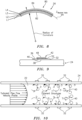
- FIG. 7 diagrammatically shows a sensing device 26 configured as a laminate body 80, and also indicates the orientation the sensing device 26 would assume when mounted on a pipe; e.g., Z-axis would be aligned with the radius of the pipe, the Y-axis would be aligned with a lengthwise axis of the pipe, and the X-axis would be aligned with the circumference of the pipe. It should be noted that FIG.
- the laminate body 80 could have an X-axis dimension equal to the circumference of the pipe to which it is to be applied (i.e., 2 ⁇ r) and a Y-axis dimension that is a function of the number of axial positions of the MFC sensors 32 within the array.
- the position of the neutral axis 94 (Z NeutralAxis ) is determined by the ratio of the sum of the products of the Elastic Modulus, thickness and location of the respective layers, and the sum of the products of the Elastic Modulus and thickness of the respective layers.
- a laminate body 80 can be configured to ensure the MFC sensors 32 are in compression for a given application (e.g., pipe diameter).
- the laminate body 80 is also typically configured to ensure the MFC sensors 32 are not subjected to strain attributable to bending deformation that substantially exceeds the manufacturer's designated maximum strain limit for the given application; i.e., for the amount of bending deformation for a given pipe diameter.
- the four layer laminate body 80 comprises a stack having a bottom layer L1 (i.e., the layer that would be contiguous with the pipe outer surface when mounted) of Kapton ® having a thickness of three thousandths of an inch (i.e., 0.003 inch, or "3 mils" / 0.0762 mm), a next layer L2 that includes the MFC sensors 32 having a thickness of six thousandths of an inch (i.e., 0.006 inch, or "6 mils" / 0.1524 mm), a next layer L3 of Kapton ® having a thickness of three thousandths of an inch (i.e., 0.003 inch, or "3 mils" / 0.0762 mm), and a top layer L4 of steel having a thickness of three thousandths of an inch (i.e., 0.003 inch, or "3 mils" / 0.0762 mm).
- a bottom layer L1 i.e., the layer that would be contiguous with the pipe outer surface when mounted
- Kapton ® is a flexible polyimide film product produced by the E.I. DuPont de Nemours and Company Corporation of Wilmington, Delaware, USA.
- the present disclosure is not limited to the aforesaid exemplary laminate body 80 layer materials, which are provided only for illustrative purposes. Using published values for the Elastic Modulus of each respective layer material, the bending strain for each layer can be determined as a function of the radius of curvature.
- the bending strains are as follows: (Table 1) Layer Number Layer Material Layer Thickness Layer Elastic Modulus Average Strain within Layer L4 Steel 0.003 inch (0.0762 mm) 3.00E+07 +0.09% L3 Kapton ® 0.003 inch (0.0762 mm) 3.63E+05 -0.06% L2 MFC Sensor 0.006 inch (0.1524 mm) 4.40E+06 -0.28% L1 Kapton ® 0.003 inch (0.0762 mm) 3.63E+05 -0.51%
- the neutral axis Z NeutralAxis
- Z NeutralAxis is located at eleven and seven tenths thousandths of an inch (0.00117 inch, or 11.7 mils / 0.02972 mm) from the outer surface of layer L1.
- Compressive strain is a negative value
- tensile strain is a positive value
- the four layer laminate body 80 stack having MFC sensors 32 disposed between the outer steel layer and the outer pipe diameter are subject to compressive strain when applied to a four inch (10.16 cm) diameter pipe - compressive strain that does not appreciably negatively affect the performance of the MFC sensors 32.
- the strains determined for the given bending deformation are steady state strains, as compared to the unsteady strain field generated by unsteady pressure fluctuations associated with fluid flow passing through a pipe that the sensing device 26 is used to sense.
- the laminate body 80 includes the same layers (e.g., same material, same thickness) but arranged such that the bottom layer L1 is steel, the next layer L2 is Kapton ® , the next layer L3 includes the MFC sensors 32, and the top layer L4 is Kapton ® .
- the bending strains are as follows: (Table 2) Layer Number Layer Material Layer Thickness Layer Elastic Modulus Average Strain within Layer L4 Kapton ® 0.003 inch (0.0762 mm) 3.63E+05 +0.51% L3 MFC Sensor 0.006 inch (0.1524 mm) 4.40E+06 +0.28% L2 Kapton ® 0.003 inch (0.0762 mm) 3.63E+05 +0.06% L1 Steel 0.003 inch (0.0762 mm) 3.00E+07 -0.09%
- the neutral axis Z NeutralAxis
- Z NeutralAxis is located at three and three tenths thousandths of an inch (0.0033 inch, or 3.3 mils / 0.0838 mm) from the outer surface of layer L1.
- the MFC sensors 32 are subject to tensile strain when applied to a four inch (10.16 cm) diameter pipe - tensile strain that does appreciably negatively affect the performance of the MFC sensors 32. From these two comparative examples, it is clear that a laminate body 80 embodiment that includes MFC sensors 32 disposed on the pipe side of the neutral axis 94 of the laminate body 80 (i.e., in compression) provides enhanced performance.
- a sensing device laminate body 80 may be configured to facilitate the sensing device 26 being used as a clamp-on device.
- a laminate body 80 stack configuration that includes an inner most layer that is releasable from a pipe surface, and configured to protect the MFC sensors 32 (during installation, use, and/removal of the sensing device), and that has the MFC sensors 32 disposed on the pipe side of the neutral axis 94 of the laminate body 80 (i.e., in compression) would be a significant improvement over prior art sensing devices.
- An inner most layer that is configured to protect the MFC sensors 32 has sufficient mechanical properties to prevent damage to the MFC sensors 32 (i.e., a sensing device in undamaged form) and thereby permits the sensing device 26 to be reused (i.e., applied to different pipe sensing sites), preferably reused a plurality of times.
- An inner most layer that is releasable from the pipe outer surface 34 may be configured so that the sensing device can be used a plurality of times (reusable); e.g., the sensing device 26 released from the pipe outer surface (e.g., adhesive removed from the inner most layer via a solvent, or an adhesive on the inner most layer that permits disengagement) with no damage, or inconsequential damage.
- a non-limiting example of such a laminate body 80 includes an inner most layer comprising a layer that may be removably adhered to the pipe outer surface (e.g., a metallic or polymeric material), and includes a remaining layer stack up that has the MFC sensors 32 disposed on the pipe side of the neutral axis 94 of the laminate body 80 (i.e., in compression); e.g., an inner most metallic layer having a first thickness, and an outer metallic layer having a second thickness greater than the first thickness which results in MFC sensors 32 disposed on the pipe side of the neutral axis 94 of the laminate body 80 (i.e., in compression).
- an inner most layer comprising a layer that may be removably adhered to the pipe outer surface (e.g., a metallic or polymeric material), and includes a remaining layer stack up that has the MFC sensors 32 disposed on the pipe side of the neutral axis 94 of the laminate body 80 (i.e., in compression); e.g., an inner most metallic layer having
- Such embodiments can have a circumferentially symmetric configuration that avoids asymmetric effects, and may also obviate the need for a clamping mechanism, thereby further avoiding asymmetric effects.
- the present disclosure is not limited to a singular sensing device laminate body 80.
- the sensing device laminate body 80 described above as including an array 30 of strain sensors 32 may be configured as a plurality of independent laminate bodies, each having fewer than all of the strain sensors within the array.
- the laminate body 80 may include "N" independent laminate body portions, each including the one or more strain sensors at the respective axial position.
- the laminate body 80 may include a plurality of independent laminate body portions, each including the one or more strain sensors at a plurality of axial positions (but less than all of the axial positions), and the like.
- a sensing device 26 embodiment having one or more strain sensors disposed at "N" different axial positions may include an independent laminate body portion for each strain sensor in the array.
- the MFC sensors 32 may be attached to the pipe outer surface 34 individually in the axial and circumferential manner described above without a strap unit 41.
- a wrap, or similar construct may be disposed radially outside of the MFC sensors 32 attached to the pipe outer surface 34.
- flow meters having MFC sensors 32 mounted in compression provide a substantially improved sensitivity that permits flow velocity measurements below three feet per second (3 f/s / 0.9144 m/s) or gas fluid flows at or below about fifteen feet per second (15 f/s / 4.5720 m/s).
- FIG. 9 illustrates a diagrammatic sectional view an MFC sensor 32 mounted on a pipe wall.
- the first face surface 36 of the MFC sensor 32 is attached to the sensor side surface 46 of the strap 42; e.g., via an adhesive 52 disposed between the first face surface 36 of the MFC sensor 32 and the strap 42.
- the MFC sensor 32 is attached to the strap 42 so the length of the sensor 32 is parallel to the circumferentially extending portion of the strap 42. In other words, when the sensor array 30 is mounted on a pipe outer surface 34, the length of the MFC sensor 32 is extending in a pipe 24 circumferential direction.
- the processing unit 28, 128, 228, 328 may include any type of computer, computing device, computational circuit, or any type of processing circuit capable of executing a series of instructions that are stored in a memory device.
- the processing unit 28, 128, 228, 328 may include one or more processors and/or multicore CPUs (collectively referred to hereinafter as a "processor" to facilitate the description).
- the processor may be a microprocessor, a digital signal processor, a co-processor, a microcontroller, a microcomputer, a central processing unit, a field programmable gate array, a programmable logic device, a state machine, logic circuitry, analog circuitry, digital circuitry, etc., and any combination thereof.
- the instructions stored in the memory device may represent logic instructions (e.g., commands), one or more algorithms, etc., for operating at least a portion of the flow meter, communicating to and from the flow meter, etc.
- the stored instructions are not limited to any particular form (e.g., program files, system data, buffers, drivers, utilities, system programs, etc.) provided they can be executed by the processor.
- the memory device may be a non-transitory computer readable storage medium configured to store instructions that when executed by the processor, cause the processor to perform or cause the performance of certain functions or commands.
- the memory device may be a single memory device or a plurality of memory devices.
- the memory device may include read-only memory, random access memory, volatile memory, non-volatile memory, static memory, dynamic memory, flash memory, cache memory, and/or any device that stores digital information.
- the processing unit 28, 128, 228, 328 is configured to communicate with the sensor array 30, and therefore includes whatever stored instructions are required to perform such communication.
- the flow meter 20, 120, 220, 320 may include one or more displays (not shown) configured to display data (e.g., data based on the sensed fluid flow 22), one or more data communication ports (input and/or output - not shown), and communication structure that permits communication to and/or from the flow meter 20, 120, 220, 320; e.g., wireless communication capability that permits a remote operator to communicate with, or receive communications from, the flow meter 20, 120, 220, 320.
- the aforesaid communications may include data transfer and operating instructions.
- the present disclosure sensor array 30 is not limited to being used with any particular algorithmic approach for processing the signals produced by the sensor array 30.
- the present disclosure sensor array 30 may be used with processing units 28, 128, 228, 328 that process the sensor array signals in a variety ways to determine the desired fluid flow parameters; e.g., fluid flow velocity, volumetric fluid flow rate, mass flow rate, etc.
- the present disclosure flow meter 20, 120, 220, 320 has the ability to determine fluid flow parameters such as fluid flow velocity, volumetric flow rate, mass flow rate, and others using one or both of the following techniques described herein below: 1) determining the velocity of unsteady pressure variations by sensing vortical disturbances (and/or other inhomogenities) traveling with the fluid flow 22 using the sensor array 30; and/or 2) determining the speed of sound of acoustical disturbances or sound waves propagating through the fluid flow 22 using the sensor array 30.
- the first technique measures the velocities associated with unsteady flow fields and/or pressure disturbances (e.g., the vortical disturbances 40).
- the MFC pressure sensors 32 sense the unsteady pressures created by the vortical disturbances 40 as these disturbances convect within the fluid flow in a known manner with reference to the fluid flow 22 in the pipe 24. Therefore, the velocity of these vortical disturbances is related to the velocity of the fluid flow 22 and hence the volumetric flow rate may be determined, as will be described in greater detail hereinafter.
- the second technique senses unsteady pressures created by acoustical disturbances propagating through the fluid to determine the speed of sound (SOS) of the acoustical disturbances.
- SOS speed of sound
- the processing unit can determine parameters such as the mass flow rate (using a determined volumetric flow rate), the consistency of the fluid (i.e., the mass/air ratio, the mass/liquid ratio, the liquid/air ratio), the density of the fluid, the enthalpy of the fluid, and the Mach number of the fluid, and the size of particles with the fluid, and the like.
- the present disclosure flow meter 20 may determine the volumetric flow rate by sensing vortical disturbances 40 (sometimes referred to as "eddies"; see FIG. 10 ) propagating with the fluid flow 22 using the sensor array 30.
- Coherent structures such as vortical disturbances 40 are an inherent feature of turbulent boundary layers present in all turbulent flows.
- the MFC sensors 32 sense the fluid flow pressure variations P 1 (t)-P N (t) at each axial location of the sensor array 30 and produce signals representative thereof. Therefore, the velocity of the vortical disturbances 40 as they pass through the portion of the pipe 24 in communication with the sensor array 30 is related to the velocity of the fluid flow 22 and hence the volumetric flow rate may be determined, as will be described in greater detail hereinafter.
- the volumetric flow may be determined by multiplying the velocity of the fluid flow by the cross-sectional area of the pipe 24.
- the Reynolds number (Re), based on pipe diameter (D), characterizes many of the engineering properties of the fluid flow 22.
- the Reynolds number is a non-dimensional ratio representing the relative importance of inertial forces to viscous forces within a flow:
- ⁇ is the fluid density
- ⁇ ' is the dynamic viscosity
- U is the volumetrically averaged flow velocity
- ⁇ is the kinematic viscosity
- D is the pipe diameter.
- the critical Reynolds number for pipe flows is ⁇ 2300.
- the Reynolds number is a similarity parameter for pipe flows, i.e. fluid flows in geometrically dissimilar pipes with the same Reynolds number are dynamically similar (Schlichting, p.12).
- a present disclosure flow meter 120 embodiment has an array of MFC pressure sensors 32, located at locations X 1 , X 2 , X 3 ,...X N , respectively.
- the MFC pressure sensors produce transit time-varying signals P 1 (t), P 2 (t), P 3 (t),...P N (t) to Fast Fourier Transform (FFT) logics 54A-54D within processing unit 128, respectively.
- the FFT logics 54A-54D calculate the Fourier transform of the time-based input signals P 1 (t)-P N (t) and provide complex frequency domain (or frequency based) signals P 1 ( ⁇ ), P 2 ( ⁇ ), P 3 ( ⁇ ),...P N ( ⁇ ) indicative of the frequency content of the input signals.
- any other technique for obtaining the frequency domain characteristics of the signals P 1 (t)-P N (t) may be used.
- the frequency signals P1( ⁇ )-P N ( ⁇ ) are fed to an array processor 56, which provides a flow signal 58 indicative of the volumetric flow rate of the fluid flow 22 and a velocity signal 60 indicative of the velocity of the fluid flow 22.
- One technique of determining the convection velocity of the vortical disturbances 40 within the fluid flow 22 is by characterizing the convective ridge of the vortical disturbances 40 using a sensor array 30 and beam forming techniques, similar to that described in U.S. Patent No. 6,609,069 , entitled “Method and Apparatus for Determining the Flow Velocity Within a Pipe". This technique of determining the convection velocity of the vortical disturbances 40 will be described in greater detail hereinafter.
- the flow metering methodology uses the convection velocity of vortical disturbances 40 with turbulent pipe flows 22 to determine the volumetric flow rate.
- the convection velocity of these vortical disturbances 40 is determined by applying arraying processing techniques to determine the speed at which the disturbances 40 convect past the sensor array 30, similar to that used in the RADAR and SONAR fields.
- ⁇ is the temporal frequency in rad/sec
- U convect is the convection velocity.
- the temporal frequency, ⁇ is linearly related to the spatial frequency, k, by the convection velocity.
- K- ⁇ plots are essentially three-dimensional power spectra in which the power of the acoustic field is decomposed into bins corresponding to specific spatial wave numbers and temporal frequencies.
- the power associated with a pressure field convecting with the fluid flow is distributed in regions, which satisfies the dispersion relationship developed above.
- the convective ridge ( Noise and Vibration Control Engineering, Beranek, L., Wiley 1992 ) and the slope of this ridge on a k- ⁇ plot indicates the convective velocity of the pressure field determine by measuring the variation in the pressure by each pressure sensor 32.
- the convective velocity of vortical disturbances 40 e.g., "eddies”
- the convective velocity of vortical disturbances 40 can be determined by constructing a k- ⁇ plot from the output of a sensor array 30 and identifying the slope of the convective ridge, as will be described in greater detail hereinafter.
- flow meter 20, 120, 220, 320 may be based on the observation that vortical disturbances 40 within a fluid flow 22 produce coherent pressure anomalies which can be sensed by the MFC sensors 32 and that the vortical disturbances 40 move at either the same velocity as the moving fluid, or at a velocity that can be correlated to the velocity of the moving fluid.
- Convective disturbances e.g., vortical disturbances 40
- a fluid flow 22 can be viewed as disturbances that are fixed to the fluid.
- These disturbances have a spatial variation associated with them. Since the disturbance can be viewed as affixed to the fluid particles, the spatial variations result in temporal variations when sensed by stationary sensors. The spatial wavelength of the disturbances that move with the fluid is thereby linked to the temporal variations observed by the stationary sensors.
- the present invention relies on utilizing array processing techniques to identify this relationship and thereby determine the convection velocity of the fluid.
- the data P 1 ( ⁇ )-P N ( ⁇ ) accumulated over a sampling interval is provided to the array processor 56, which performs a spatial-temporal (two-dimensional) transform of the sensor data, from an x-t domain to the k- ⁇ domain, and then calculates the power in the k- ⁇ plane, as represented by k- ⁇ plot.
- the array processor 56 determines the wavelength and so the (spatial) wavenumber k, and also the (temporal) frequency and so the angular frequency ⁇ , of various of the spectral components created by the vortical disturbances.
- the array processor 56 determines the wavelength and so the (spatial) wavenumber k, and also the (temporal) frequency and so the angular frequency ⁇ , of various of the spectral components created by the vortical disturbances.
- the power in the k- ⁇ plane shown in a k- ⁇ plot of FIG. 12 so determined will exhibit a structure that is called a convective ridge 62.
- the convective ridge 62 represents the concentration of the vortical disturbances 40 that convect with the fluid flow 22 and is a mathematical manifestation of the relationship between the spatial variations and temporal variations described above.
- Such a plot will indicate a tendency for k- ⁇ pairs to appear more or less along a line 64 with some slope, the slope indicating the flow velocity, as is described in more detail below.
- the power in the k- ⁇ plane so determined is then provided to a convective ridge identifier which uses one or another feature extraction method to determine the location and orientation (slope) of any convective ridge 62 present in the k- ⁇ plane. Finally, information including the convective ridge 62 orientation (slope) is used to determine the flow velocity.
- the array processor 56 may use standard so-called beam forming, array processing, or adaptive array-processing algorithms; i.e. algorithms for processing the sensor 32 signals using various delays and weighting to create suitable phase relationships between the signals provided by the different sensors 32, thereby creating phased antenna array functionality.
- the prior art teaches many algorithms of use in spatially and temporally decomposing a signal from a phased array of sensors, and the present invention is not restricted to any particular algorithm.
- One particular adaptive array processing algorithm is the Capon method/algorithm.
- the Capon method is a non-limiting example of an acceptable array processing algorithm.
- Other adaptive array processing algorithms e.g., the MUSIC algorithm may be used alternatively.
- FIG. 13 illustrates a schematic drawing of an embodiment of the present disclosure wherein the processing unit 228 is configured to determine the speed of sound of acoustical disturbances or sound waves propagating through the fluid using the sensor array 30.
- the MFC sensors 32 within the sensor array 30 sense for strain / unsteady pressures produced by acoustical disturbances present within the fluid flow 22 passing through the pipe 24. The unsteady pressures are indicative of the SOS propagating through the fluid.
- the MFC sensors 32 produce signals (P 1 -P N ) representative of the fluid flow pressure variations and those signals are provided to the processing unit 228.
- the processing unit 228, processes the signals (e.g., using array processing unit 256 and Speed of Sound processing unit 257) to determine a fluid flow parameter such as the speed of sound (SOS) within the fluid flow. Knowing the pressure and/or temperature of the fluid flow 22 and the speed of sound of the acoustical disturbances, the processing unit 228 can also determine other fluid flow parameters such as the gas volume fraction (GVF) of the fluid flow; e.g., in a manner similar to that described in U.S. Patent Nos. 7,359,803 ; 7,062,976 ; 7,058,549 ; 7,032,432 ; 6,732,575 ; 6,609,069 ; 6,587,798 ; and 6,354,147 .
- GVF gas volume fraction
- the acoustical disturbances sensed by the sensor array 30 may be "naturally" produced within the environment of the pipe 24 (e.g., passive noise generated by pumps, valves, motors, the turbulent mixture itself, etc.).
- the present disclosure also contemplates providing one or more acoustic sources 66 to enable the measurement of the speed of sound propagating through the fluid flow 22 for instances of acoustically quiet flow.
- the acoustic sources 66 may be disposed at the input end or output end of the sensor array 30, or at both ends as shown.
- the acoustics sources 66 are not necessary and the apparatus passively detects the acoustic ridge provided in the flow 22.
- FIG. 14 Another embodiment of the present disclosure configured to determine the speed of sound propagating through the fluid flow 22 is shown in FIG. 14 .
- the flow meter embodiment shown in FIG. 14 includes an array of MFC sensors 32, disposed at axially spaced apart locations X 1 , X 2 , X 3 , and X N .
- the MFC sensors 32 sense for strain / pressure variations and produce time-varying signals P 1 (t), P 2 (t), P 3 (t),...P N (t) on lines 368A-368D to the processing unit 328.
- the processing unit 328 includes Fast Fourier Transform (FFT) logics 354A-354D that calculate the Fourier transform of the time-based input signals P 1 (t)-P N (t) and provide complex frequency domain (or frequency based) signals P 1 ( ⁇ ), P 2 ( ⁇ ), P 3 ( ⁇ )...P N ( ⁇ ) on lines 370A-370D indicative of the frequency content of the input signals.
- FFT Fast Fourier Transform
- any other technique for obtaining the frequency domain characteristics of the signals P 1 (t)-P N (t) may be used.
- the cross-spectral density and the power spectral density may be used to form a frequency domain transfer functions (or frequency response or ratios) discussed hereinafter.
- the frequency signals P 1 ( ⁇ )-P N ( ⁇ ) are fed to an array processing unit 356 which provides a signal to line 372 indicative of the speed of sound of the mixture a mix .
- the a mix signal is provided to an entrained gas processing unit 374, similar to the SOS processing unit 257, which converts a mix to a percent composition of a mixture and provides a gas volume fraction or % Comp signal.
- the data from the array of sensors 32 may be processed in any domain, including the frequency/spatial domain, the temporal/spatial domain, the temporal/wave-number domain or the wave-number/frequency (k- ⁇ ) domain.
- any known array processing technique in any of these or other related domains may be used if desired, similar to the techniques used in the fields of SONAR and RADAR.
- One such technique of determining the speed of sound propagating through the flow 22 is using array processing techniques to define an acoustic ridge in the k- ⁇ plane as shown in FIG. 15 .
- the slope of the acoustic ridge is indicative of the speed of sound propagating through the flow 22.
- the speed of sound (SOS) is determined by applying SONAR array processing techniques to determine the speed at which the one dimensional acoustic waves propagate past the axial array of unsteady pressure measurements distributed along the pipe 24.
- the processing unit 328 performs a Fast Fourier Transform (FFT) of the time-based pressure signals P 1 (t)-P N (t) to convert the pressure signal into the frequency domain.
- FFT Fast Fourier Transform
- the power of the frequency-domain pressure signals are then determined and defined in the k- ⁇ plane by using array processing algorithms (such as Capon and Music algorithms).
- the acoustic ridge in the k- ⁇ plane, as shown in the k- ⁇ plot of FIG. 15 is then determined.
- the speed of sound (SOS) is determined by measuring slope of the acoustic ridge.
- the gas volume fraction is then calculated or otherwise determined, as described hereinafter.
- the flow meter of the present invention uses known array processing techniques, in particular the Minimum Variance, Distortionless Response, or other adaptive array processing techniques (MVDR, Music, or Capon technique), to identify pressure fluctuations, which convect with the materials flowing in a conduit and accurately ascertain the velocity, and thus the flow rate, of said material.
- MVDR Minimum Variance, Distortionless Response
- MVDR Minimum Variance, Distortionless Response
- Capon technique adaptive array processing techniques
- These processing techniques utilize the covariance between multiple sensors 32 at a plurality of frequencies to identify signals that behave according to a given assumed model; e.g., in the case of the apparatus 320, a model, which represents pressure variations convecting at a constant speed across the sensors comprising the flow meter sensing device 26.
- FIG. 16 illustrates flow diagram representative of the apparatus 320 of FIG. 14 .
Landscapes
- Physics & Mathematics (AREA)
- General Physics & Mathematics (AREA)
- Fluid Mechanics (AREA)
- Acoustics & Sound (AREA)
- Immunology (AREA)
- Health & Medical Sciences (AREA)
- Life Sciences & Earth Sciences (AREA)
- Chemical & Material Sciences (AREA)
- Analytical Chemistry (AREA)
- Biochemistry (AREA)
- General Health & Medical Sciences (AREA)
- Pathology (AREA)
- Mechanical Engineering (AREA)
- Engineering & Computer Science (AREA)
- Electromagnetism (AREA)
- Measuring Volume Flow (AREA)
Description
- The present application is entitled to the benefit of subject matter disclosed in
U.S. Provisional Patent Application Serial No. 62/872,382, filed July 10, 2019 - The present disclosure relates to an apparatus for determining one or more parameters of a homogeneous or non-homogeneous fluid flowing within a conduit.
- Numerous technologies have been implemented to measure fluid flow parameters such as flow velocity, volumetric flow rate, and mass flow rate of fluids in industrial processes. Some of the more common approaches are based upon ultrasonic time of flight and/or Doppler effects, Coriolis effects, rotating wheels, electromagnetic induction, and pressure differentials. Each of these techniques has certain drawbacks. For example, invasive techniques that rely on insertion of a probe into the flow, or geometry changes in the pipe, may be disruptive to the process and prone to clogging. Other methods such as ultrasonics may be susceptible to entrained gases or flow stratification. Meters that use rotating wheels or moving parts are subject to reliability issues. Coriolis meters are intrusive and limited by multiphase flow effects and pipe size limitations.
-
U.S. Patent No. 7,058,549 describes an apparatus and method for measuring unsteady pressures in a pipe. The apparatus includes piezoelectric film (PVDF) sensors mounted on a stainless steel strap that is clamped to the exterior of a pipe. The sensors are disposed in an array and are configured to sense unsteady pressures associated with vortical and /or other disturbances traveling within a fluid passing through the pipe, and/or acoustical disturbances traveling within the pipe. The unsteady pressures are analyzed to determine a fluid flow parameter such as volumetric flow rate or process fluid sound speed. For measuring a convective velocity, the aforesaid apparatus works very well under most fluid flow conditions. However, under certain low flow velocity circumstances (e.g., liquid flow velocities as low as three feet per second (3 f/s / 0.9144 m/s), gas flow velocities as low as fifteen feet per second (15 f/s / 4.5720 m/s), etc.), the aforesaid apparatus may not be able to produce accurate results. "Ultrasound Flow Sensor Based on Arrays of Piezoelectric Transducers Integrated in a Composite"authored by Kunadt et al. describes a flow sensor integrated in the walls of a flow channel made of composites.
DE102013101950A1 describes an arrangement having a flow channel portion provided with a rectangular cross-section, and ultrasonic transducers. - What is needed, therefore, is a fluid flow sensing apparatus that performs well for a variety of different velocity fluid flows traveling within a pipe.
- According to the claimed invention, an apparatus for measuring a parameter of a fluid flow passing within a pipe is provided as defined in
claim 1. Preferred embodiments are defined by the dependent claims 2-12. - According to an aspect of the present disclosure, an apparatus for measuring one or more parameters of a fluid flow passing within a pipe is provided. The pipe has an outer radial surface and a circumference. The apparatus includes a sensing device and a processing unit. The sensing device includes a sensor array that has at least one first macro fiber composite (MFC) strain sensor disposed at a first axial position, and at least one second MFC strain sensor disposed at a second axial position. The first axial position and the second axial position are spaced apart from one another. The at least one first MFC strain sensor and at least one second MFC strain sensor are both configured to produce signals representative of pressure variations of the fluid flow passing within the pipe. Each first MFC sensor and each second MFC sensor has a first sensitivity along a first axis and a second sensitivity along a second axis, which second axis is orthogonal to the first axis, and the second sensitivity is substantially less than the first sensitivity. The sensing device is configured for attachment to the pipe outer radial surface so that the at least one first MFC strain sensor and the at least one second MFC strain sensor each have their respective first axis substantially aligned with the circumference of the pipe. The processing unit is configured to receive the signals from the at least one first MFC strain sensor and the at least one second MFC strain sensor sensing device, and measure the one or more fluid flow parameters based on the signals.
- In any of the aspects or embodiments described above and herein, the sensing device may include a strap unit disposed radially outside of the array of sensors.
- In any of the aspects or embodiments described above and herein, the sensing device may include an adhesive operable to attach the at least one first MFC strain sensor and the at least one second MFC strain sensor to a surface of the strap unit.
- In any of the aspects or embodiments described above and herein, the strap unit may be configured to clamp the sensing device to the pipe outer radial surface.
- In any of the aspects or embodiments described above and herein, the sensing device may include an adhesive operable to attach the at least one first MFC strain sensor and the at least one second MFC strain sensor to the pipe outer radial surface.
- In any of the aspects or embodiments described above and herein, the sensing device may be configured for attachment to the pipe outer radial surface so that the at least one first MFC strain sensor and the at least one second MFC strain sensor are subjected to compressive strain.
- In any of the aspects or embodiments described above and herein, the sensing device may have a laminate body that includes a stack of layers including a sensor layer that includes the sensor array, and the laminate body has a neutral axis, and the sensing device may be configured for attachment to the pipe outer radial surface so that the sensor layer is disposed within the laminate body between the neutral axis and the pipe outer radial surface.
- In any of the aspects or embodiments described above and herein, the laminate body may include an inner most layer, and the sensing device may be configured for attachment to the pipe outer radial surface so that the inner most layer is contiguous with the pipe outer radial surface, and the sensing device may be configured so that the inner most layer is releasable from the pipe outer radial surface with the sensing device in an undamaged form.
- According to another aspect of the present disclosure, an apparatus for measuring one or more parameters of a fluid flow passing within a pipe is provided. The pipe has an outer radial surface and a circumference. The apparatus includes a sensing device and a processing unit. The sensing device includes a sensor array disposed within a laminate body having a stack of layers. The sensor array is disposed within a sensor layer of the stack of layers. The laminate body has a neutral axis. The sensor array includes at least one first macro fiber composite (MFC) strain sensor disposed at a first axial position, and at least one second MFC strain sensor disposed at a second axial position. The first axial position and the second axial position are spaced apart from one another. The at least one first MFC strain sensor and at least one second MFC strain sensor are both configured to produce signals representative of pressure variations of the fluid flow passing within the pipe. The sensing device is configured for attachment to the pipe outer radial surface so that the sensor layer is disposed within the laminate body between the neutral axis and the pipe outer radial surface. The processing unit is configured to receive the signals from the at least one first MFC strain sensor and the at least one second MFC strain sensor sensing device, and measure the at least one fluid flow parameter based on the signals.
- In any of the aspects or embodiments described above and herein, the sensing device may include a strap unit configured to clamp the laminate body to the pipe outer radial surface.
- In any of the aspects or embodiments described above and herein, the sensing device may include a wrap configured to hold the laminate body to the pipe outer radial surface.
- In any of the aspects or embodiments described above and herein, the laminate body may be configured to be attachable to the pipe outer radial surface.
- In any of the aspects or embodiments described above and herein, the sensing device may be configured for attachment to the pipe outer radial surface so that the at least one first MFC strain sensor and the at least one second MFC strain sensor are subjected to compressive strain.
- In any of the aspects or embodiments described above and herein, each first MFC sensor and each second MFC sensor may have a first sensitivity along a first axis and a second sensitivity along a second axis, which second axis is orthogonal to the first axis, and the second sensitivity is substantially less than the first sensitivity, and the sensing device may be configured for attachment to the pipe outer radial surface so that the at least one first MFC strain sensor and the at least one second MFC strain sensor each have their respective first axis substantially aligned with the circumference of the pipe.
- According to an aspect of the present disclosure, an apparatus for measuring one or more parameters of a fluid flow passing within a pipe is provided. The pipe has an outer radial surface and a circumference. The apparatus includes a sensing device and a processing unit. The sensing device includes a sensor array having at least one first macro fiber composite (MFC) strain sensor disposed at a first axial position, and at least one second MFC strain sensor disposed at a second axial position. The first axial position and the second axial position are spaced apart from one another. The at least one first MFC strain sensor and at least one second MFC strain sensor are both configured to produce signals representative of pressure variations of the fluid flow passing within the pipe. The processing unit is configured to receive the signals from the at least one first MFC strain sensor and the at least one second MFC strain sensor sensing device, and measure at least one fluid flow parameter based on the signals.
- In any of the aspects or embodiments described above and herein, the sensing device may be configured for attachment to the pipe outer radial surface so that the at least one first MFC strain sensor and the at least one second MFC strain sensor are subjected to compressive strain.
- The foregoing features and elements may be combined in various combinations without exclusivity, unless expressly indicated otherwise. These features and elements as well as the operation thereof will become more apparent in light of the following description and the accompanying drawings. It should be understood, however, the following description and drawings are intended to be exemplary in nature and non-limiting.
-
-
FIG. 1 is a schematic illustration of an apparatus having an array of segmented sensors disposed along a pipe for measuring a parameter of a fluid flowing in the pipe and an associated processing unit, in accordance with the present invention. -
FIG. 2 is a diagrammatic illustration of a MFC strain sensor that may be utilized to sense fluid pressure variations within a pipe. -
FIGS. 3-5 are side sectional views of a sensor array having a plurality of MFC pressure sensors mounted on a pipe. -
FIG. 6 is a perspective view of a sensor array strap. -
FIG. 7 is a diagrammatic isometric view of a sensing device embodiment. -
FIG. 8 is a diagrammatic end view of a sensing device embodiment in bending deformation. -
FIG. 9 is a diagrammatic view of an MFC sensor and strap mounted on a pipe wall. -
FIG. 10 is a cross-sectional view of a pipe having a turbulent pipe flowing having coherent structures therein. -
FIG. 11 is a schematic illustration of a flow meter embodiment. -
FIG. 12 a k-ω plot of data that illustrates slope of a convective ridge, and a plot of the optimization function of the convective ridge. -
FIG. 13 is a schematic illustration of a flow meter embodiment. -
FIG. 14 is a schematic illustration of a flow meter embodiment. -
FIG. 15 a k-ω plot of data that illustrates slope of the acoustic ridges traveling in both directions of the pipe. -
FIG. 16 is a functional diagram of an apparatus embodying the present invention. - Referring to
FIG. 1 , an apparatus or flow meter, generally shown as 20, is provided to measure the unsteady pressures (P(t)) of a homogeneous ornon-homogeneous fluid 22 flowing within apipe 24 to determine a parameter or characteristic of the fluid. Thepipe 24 may be described as extending axially along an axial centerline "A". As will be described hereinafter, thefluid flow 22 traveling through thepipe 24, although typically (but not necessarily) turbulent in nature, may be described as collectively traveling through thepipe 24 in a direction parallel to the axial centerline A of thepipe 24. Theflow meter 20 can measure parameters of a single phase fluid (e.g., gas, liquid or liquid/liquid mixture) and/or a multi-phase mixture (e.g., process flow) flowing through apipe 24. The multi-phase mixture may be a two-phase liquid/gas mixture, a solid/gas mixture or a solid/liquid mixture, gas entrained liquid or a three-phase mixture. As will be described below, at least portions of theflow meter 20 are disposed in communication with an exterior surface of thepipe 24. As used herein, the term "pipe" is used to generically refer to a conduit having an enclosed passage through which a fluid flow may be passed. The present disclosure is not, however, limited to use with a cylindrically-shaped conduit. Some embodiments of the presentdisclosure flow meter flow meter 20 to be installed, maintained, serviced and removed without having to interrupt a fluid flow traveling within the interior of thepipe 24. - The
flow meter 20 includes asensing device 26 and aprocessing unit 28. Thesensing device 26 that comprises anarray 30 ofstrain sensors 32 axially spaced along theouter surface 34 of thepipe 24. Theaforesaid sensors 32 are configured to sense strain within the pipe wall (which strain is often highly correlated to unsteady pressures within the fluid flow) and provide signals representative thereof. The signals (diagrammatically shown inFIGS. 1 ,11 , and14 as "P1(t) -PN(t)") are provided to aprocessing unit 28, which processes the sensor signals and determines at least one parameter of thefluid flow 22. The aforesaid at least one fluid flow parameter may include, but is not limited to, the volumetric flow rate, process fluid speed of sound, the mass flow rate, the consistency or composition of the fluid flow, the density of the fluid flow, the Mach number of the fluid flow, the size of a particle traveling within the fluid flow, the air/mass ratio of the fluid flow, and/or the percentage of entrained air within a liquid or slurry. - The
sensor array 30 includes at least twosensors 32 in communication with theouter surface 34 of thepipe 24, axially spaced apart from one another. Each of thesensors 32 is a macro fiber composite (MFC) type strain sensor (referred to hereinafter as an "MFC sensor 32"). MFC sensors typically consist of piezofibers (e.g., rectangular piezo ceramic rods) sandwiched between layers of adhesive, electrodes and polyimide film. The electrodes are attached to the film in an interdigitated pattern. The pliable and conformable features ofMFC sensors 32 enables them to sense deformations, noise and vibrations. In preferred embodiments of the present disclosure, eachMFC sensor 32 is configured to have an anisotropic strain sensitivity; i.e., a strain sensitivity that is greater in a first orthogonal direction, than in a second orthogonal direction. AnMFC sensor 32 having an anisotropic strain sensitivity typically has greater strain sensitivity along the axis of its piezofibers as compared to its strain sensitivity in a direction orthogonal to the piezofibers. Referring toFIG. 2 , eachMFC sensor 32 may be described as having afirst face surface 36, asecond face surface 38, a length, a width, and a thickness. As described herein, the piezofibers of theMFC sensors 32 extend in the lengthwise direction of the MFC sensor. HenceMFC sensors 32 configured to have an anisotropic strain sensitivity as described herein, have a strain sensitivity along the lengthwise axis of the sensor that is greater than its strain sensitivity along the widthwise axis of the sensor. A pipe containing a fluid flow which may be sensed using the present disclosure apparatus will typically be subjected to a strain field that includes hoop strain (i.e., circumferential) associated with internal pressure variations associated with the fluid flow, as well as axial strain associated with pipe bending vibrations. The hoop strain can be measured to provide beneficial information relating to fluid flow parameters. The axial strain, in contrast, typically represents undesirable noise and detrimentally affects the signal-to-noise ratio of sensors. When mounted on apipe 24 according to the present disclosure,anisotropic MFC sensors 32 may be mounted to provide a greater strain sensitivity in apipe 24 circumferential direction; i.e., mounted with the lengthwise axis of theMFC sensor 32 substantially parallel to the circumferential direction. Mounting theanisotropic MFC sensors 32 in this manner positions their "greater sensitivity" axis with potential hoop strain, and their "lesser sensitivity" axis with the undesirable axial pipe bending strain. Hence, the signal-to-noise ratio with theMFC sensors 32 is enhanced. Prior art flow meters often use sensors (e.g., some PVDFs) having orthogonal strain sensitivities that are more isotropic than theanisotropic MFC sensors 32 and therefore have a lower signal-to-noise ratio when used in a similar flow meter application. A non-limiting example of anMFC sensor 32 that may be used in the present disclosure is a sensor model M-8522-P2 produced by the Smart Material GmbH of Germany. It should be noted however, that many different types of MFC sensors can be used with the present disclosure, and the present disclosure is not therefore limited to any particular model MFC sensor. - The number of
MFC sensors 32 within thesensor array 30 may vary depending upon the application, and the present disclosure is not therefore limited to any particular number ofMFC sensors 32 other than more than two. The number of MFC sensor axial positions (e.g., X1-XN) within thesensor array 30 may also vary depending upon the application (e.g.,sensors 32 disposed at as many as sixteen different axial positions), and the present disclosure is not therefore limited to any particular number of axial sensor positions other than at least two. - At a given axial position, the
sensor array 30 has at least oneMFC sensor 32. Typically, however, thesensor array 30 may have a plurality ofMFC sensors 32 disposed around the circumference of the pipe 24 (when mounted on the pipe 24) at a given axial position (e.g., X1-XN). For example as shown inFIG. 3 , thesensor array 30 includes a pair ofMFC sensors 32 at each axial position, eachsensor 32 sensing a substantial portion of a respective half of thepipe 24. InFIG. 4 , thesensor array 30 includes four (4)MFC sensors 32 at each axial position, eachsensor 32 sensing a substantial portion of a respective quarter of thepipe 24. InFIG. 5 , thesensor array 30 includes twelve (12)MFC sensors 32 at each axial position, spaced around thepipe 24 circumference. Thesensor array 30 may be configured such that the plurality ofMFC sensors 32 at a given axial position are uniformly or non-uniformly spaced around the circumference of thepipe 24 when thesensor array 30 is mounted. Thesensor array 30 may be configured such that each of theMFC sensors 32 at a given axial position may be the same configuration (e.g., type, dimensions, etc.), or alternatively thesensor array 30 may be configured such that the plurality ofMFC sensors 32 at a given axial position may include differentconfiguration MFC sensors 32; e.g., the plurality ofsensors 32 including at least one firstconfiguration MFC sensor 32 and at least one secondconfiguration MFC sensor 32. - The circumferentially spaced
MFC sensors 32 at a given axial position may be connected in parallel. For example, the leads of oneMFC sensor 32 may be directly connected to anadjacent MFC sensor 32. Alternatively, eachMFC sensor 32 at an axial position (e.g., X1-XN) may be connected in series, or eachMFC sensor 32 at an axial position (e.g., X1-XN) may be directly connected to theprocessing unit 28. The present disclosure is not limited to these connection embodiments. In those embodiments wherein eachMFC sensor 32 is directly connected to theprocessing unit 28, theprocessing unit 28 may selectively process signals from therespective MFC sensor 32 independently. - The axial spacing (e.g., X1-XN) between the
MFC sensors 32 may vary depending on the application for which theflow meter 20 is designed; e.g., sensing for different types of unsteady pressures may benefit from different sensor axial spacings. For example, characteristics ofvortical disturbances 40 within a given fluid flow 22 (and the unsteady pressures they create) may influence a preferred overall axial length of asensor array 30, and also the inter-sensor axial spacing ofMFC sensors 32 within thesensor array 30; e.g.,axial sensor 32 spacing that is less than a coherence length of thevortical disturbances 40 which is typically on the order of a pipe diameter. Typically, the inter-sensor spacing (X1, X2, X3,...XN) is uniform (e.g., X1 = X2 = X3, etc.), but uniform inter-sensor spacing is not required. The inter-sensor spacing is also typically known and the distances are typically stored in theprocessing unit 28 instructions. - We discovered that the performance of
MFC sensors 32 can vary significantly depending on the manner in which thesensors 32 are mounted on a surface (e.g., a pipe exterior surface). Specifically, we discovered that the performance of anMFC sensor 32 placed in tension degrades notably (e.g., signal integrity erosion), but the performance of the sametype MFC sensor 32 placed in magnitude compression does not appreciably degrade, provided the strain associated with the compression is close to or within strain limits of theMFC sensor 32. The present disclosure leverages this discovery to provide severaladvantageous sensor 32 mounting arrangements. - In some embodiments, the
sensing device 26 includes astrap unit 41 having a plurality ofstraps 42, and may include one or more spines connecting thestraps 42.FIG. 6 illustrates a non-limiting example of astrap unit 41 having a plurality ofstraps 42, each connected to afirst side spine 44A, acentral spine 44B, and asecond side spine 44C. Eachstrap 42 may be described as having afirst portion 42A extending between thefirst side spine 44A and thecentral spine 44B, and asecond portion 42B extending between thesecond side spine 44C and thecentral spine 44B. Each strap 42 (e.g.,first portion 42A,second portion 42B, spines 44) may further be described as having asensor side surface 46 and an opposedexterior surface 48. The first andsecond attachment spines bolts 50. When attached to apipe 24, the strapping configuration is typically mounted such that thestraps 42 extend circumferentially around the pipeouter surface 34, and thespines 44A-44C extend axially along the pipeouter surface 34. The present disclosure is not limited to anyparticular strap unit 41 configuration. - In those embodiments wherein the
sensing device 26 includes astrap unit 41, theMFC sensors 32 may be attached to the sensor side surfaces 46 of thestraps 42 in the axial and circumferential manner described above. Alternatively, the MFC sensors may be attached to the pipe outer surface 34 (e.g., using an adhesive) in the axial and circumferential manner described above and the strap unit 41 (independent of the MFC sensors 32) then disposed radially outside of theMFC sensors 32. This mounting configuration (sensors 32 between thestraps 42 and the pipe outer surface 34) places theMFC sensors 32 in compression, and is in direct contrast to all commercially available flow meters of which we are aware; i.e., configurations in which the straps are disposed between the pipeouter surface 34 and the sensors, and the sensors are loaded in tension. - In those embodiments wherein the
sensing device 26 includes astrap unit 41 and theMFC sensors 32 are disposed between thestraps 42 and pipe outer surface 34 (i.e., loaded in compression), thestrap unit 41 may be configured to clamp thesensors 32 to the pipeouter surface 34. The present disclosure does not require astrap unit 41 that clamp thesensor array 30 to the pipeouter surface 34. Alternatively, thestrap unit 41 andMFC sensors 32 may be wrapped around the pipeouter surface 34 and thesensors 32 held in good contact with the pipeouter surface 34 with an adhesive adhering thesensors 32 andstrap unit 41 directly to the pipe; e.g., with tape or other material that allows the strap and sensors to be secured to the pipe with some nominal tensile load. A wrap, or similar construct, may provide a means to attach thesensors 32 to the pipe in an axisymmetric manner. The adhesive and or nominal tension loads maintains good contact between the sensor and the pipe, and avoids any undesirable vibrational impact that may be associated with a non-symmetrical clamping arrangement. - Referring to
FIG. 7 , thesensing device 26 is configured as alaminate body 80 that includes anarray 30 of strain sensors 32 (e.g., seeFIGS. 3-5 ) disposed within a layer of thelaminate body 80 with the axial and circumferential spacing as described above. As described herein, a sensingdevice laminate body 80 may be clamped to a pipe outer surface, or held in place relative to the pipe outer surface by a wrap or similar construct, or may itself be configured for attachment to the pipe outer surface. Thelaminate body 80 may be described as having apipe side surface 82 and an oppositeouter surface 84, extending axially between a firstaxial end 86 and a secondaxial end 88, and laterally between a firstcircumferential end 90 and a secondcircumferential end 92. Thelaminate body 80 comprises a plurality of layers, including a layer that includes the array of MFC sensors 32 (i.e., a "sensor layer"). As indicated above, we discovered that the performance ofMFC sensors 32 can vary significantly depending on whether theMFC sensors 32 are placed in tension or in compression. Thelaminate body 80 configuration provides a mechanism to ensure theMFC sensors 32 are subjected to a predetermined level of compression; e.g., based on: a) the position of theMFC sensors 32 within the stack of layers within thelaminate body 80; b) the material properties of each layer within the stack; and c) the bending deformation to which theMFC sensor 32 is subjected (i.e., the radius of curvature that thelaminate body 80 will assume when installed on the pipe), including any combination thereof. The layered configuration of thelaminate body 80 is advantageous for several reasons. For example, the layered configuration of thelaminate body 80 facilitates manufacture; i.e., thelaminate body 80 can be readily assembled as a planar body on a planar surface. As another example, the layered configuration of thelaminate body 80 can be designed for a specific pipe diameter; e.g., the position of theMFC sensors 32 within the stack of layers within thelaminate body 80 and/or the material properties of each layer within the stack can be selected to ensure theMFC sensors 32 are in compression (when thesensing device 26 is installed) for a selected pipe diameter. - The
laminate body 80 possesses aneutral axis 94, and the stack of layers and the mechanical properties of those layers define the position of theneutral axis 94. Theneutral axis 94 is the plane within thelaminate body 80 which experiences no bending stress when thelaminate body 80 is deformed in bending. To illustrate,FIG. 7 diagrammatically shows asensing device 26 configured as alaminate body 80, and also indicates the orientation thesensing device 26 would assume when mounted on a pipe; e.g., Z-axis would be aligned with the radius of the pipe, the Y-axis would be aligned with a lengthwise axis of the pipe, and the X-axis would be aligned with the circumference of the pipe. It should be noted thatFIG. 7 diagrammatically illustrates the sensingdevice laminate body 80 having a rectangular shape to facilitate the description, and the present disclosure is not limited to the rectangular configuration. That said, in some embodiments thelaminate body 80 could have an X-axis dimension equal to the circumference of the pipe to which it is to be applied (i.e., 2πr) and a Y-axis dimension that is a function of the number of axial positions of theMFC sensors 32 within the array. The location of theneutral axis 94 within thelaminate body 80 may be determined using the following equation:
laminate body 80; e.g., thepipe side surface 82 of thelaminate body 80. Hence, the position of the neutral axis 94 (ZNeutralAxis) is determined by the ratio of the sum of the products of the Elastic Modulus, thickness and location of the respective layers, and the sum of the products of the Elastic Modulus and thickness of the respective layers. - Referring to
FIGS. 7 and8 when thelaminate body 80 deformed by bending (e.g., applied to the outer surface of a pipe), the amount of strain that develops in each respective layer is proportional to the ratio of the distance between the respective layer and theneutral axis 94 of thelaminate body 80, divided by the radius of curvature of the bending deformation (i.e., the pipe radius), and may be determined using the following equation:
laminate body 80 can be configured to ensure theMFC sensors 32 are in compression for a given application (e.g., pipe diameter). Thelaminate body 80 is also typically configured to ensure theMFC sensors 32 are not subjected to strain attributable to bending deformation that substantially exceeds the manufacturer's designated maximum strain limit for the given application; i.e., for the amount of bending deformation for a given pipe diameter. - To illustrate further, consider the four
layer laminate body 80 shown inFIG. 7 , and as a non-limiting example assume that the fourlayer laminate body 80 comprises a stack having a bottom layer L1 (i.e., the layer that would be contiguous with the pipe outer surface when mounted) of Kapton® having a thickness of three thousandths of an inch (i.e., 0.003 inch, or "3 mils" / 0.0762 mm), a next layer L2 that includes theMFC sensors 32 having a thickness of six thousandths of an inch (i.e., 0.006 inch, or "6 mils" / 0.1524 mm), a next layer L3 of Kapton® having a thickness of three thousandths of an inch (i.e., 0.003 inch, or "3 mils" / 0.0762 mm), and a top layer L4 of steel having a thickness of three thousandths of an inch (i.e., 0.003 inch, or "3 mils" / 0.0762 mm). Kapton® is a flexible polyimide film product produced by the E.I. DuPont de Nemours and Company Corporation of Wilmington, Delaware, USA. The present disclosure is not limited to the aforesaidexemplary laminate body 80 layer materials, which are provided only for illustrative purposes. Using published values for the Elastic Modulus of each respective layer material, the bending strain for each layer can be determined as a function of the radius of curvature. Assuming a radius of curvature (two inches / 5.08 cm) associated with a four inch (10.16 cm) diameter pipe, the bending strains are as follows:(Table 1) Layer Number Layer Material Layer Thickness Layer Elastic Modulus Average Strain within Layer L4 Steel 0.003 inch (0.0762 mm) 3.00E+07 +0.09% L3 Kapton® 0.003 inch (0.0762 mm) 3.63E+05 -0.06% L2 MFC Sensor 0.006 inch (0.1524 mm) 4.40E+06 -0.28% L1 Kapton® 0.003 inch (0.0762 mm) 3.63E+05 -0.51% exemplary laminate body 80 stack, the neutral axis (ZNeutralAxis) is located at eleven and seven tenths thousandths of an inch (0.00117 inch, or 11.7 mils / 0.02972 mm) from the outer surface of layer L1. Compressive strain is a negative value, and tensile strain is a positive value. As seen from the strain values in Table 1, the fourlayer laminate body 80 stack havingMFC sensors 32 disposed between the outer steel layer and the outer pipe diameter are subject to compressive strain when applied to a four inch (10.16 cm) diameter pipe - compressive strain that does not appreciably negatively affect the performance of theMFC sensors 32. It should be noted that the strains determined for the given bending deformation are steady state strains, as compared to the unsteady strain field generated by unsteady pressure fluctuations associated with fluid flow passing through a pipe that thesensing device 26 is used to sense. - To illustrate still further, consider a variant of the four layer sensing device laminate body shown in
FIG. 7 , wherein thelaminate body 80 includes the same layers (e.g., same material, same thickness) but arranged such that the bottom layer L1 is steel, the next layer L2 is Kapton®, the next layer L3 includes theMFC sensors 32, and the top layer L4 is Kapton®. Again, assuming a radius of curvature (two inches / 5.08 cm) associated with a four inch (10.16 cm) diameter pipe, the bending strains are as follows:(Table 2) Layer Number Layer Material Layer Thickness Layer Elastic Modulus Average Strain within Layer L4 Kapton® 0.003 inch (0.0762 mm) 3.63E+05 +0.51% L3 MFC Sensor 0.006 inch (0.1524 mm) 4.40E+06 +0.28% L2 Kapton® 0.003 inch (0.0762 mm) 3.63E+05 +0.06% L1 Steel 0.003 inch (0.0762 mm) 3.00E+07 -0.09% MFC sensors 32 are disposed radially outside of the steel layer within the laminate stack (and the steel layer is disposed contiguous with the pipe outer surface, theMFC sensors 32 are subject to tensile strain when applied to a four inch (10.16 cm) diameter pipe - tensile strain that does appreciably negatively affect the performance of theMFC sensors 32. From these two comparative examples, it is clear that alaminate body 80 embodiment that includesMFC sensors 32 disposed on the pipe side of theneutral axis 94 of the laminate body 80 (i.e., in compression) provides enhanced performance. - As stated above, the present disclosure is not limited to the sensing
device laminate body 80 layer examples provided above. In some embodiments, for example, a sensingdevice laminate body 80 may be configured to facilitate thesensing device 26 being used as a clamp-on device. Alaminate body 80 stack configuration that includes an inner most layer that is releasable from a pipe surface, and configured to protect the MFC sensors 32 (during installation, use, and/removal of the sensing device), and that has theMFC sensors 32 disposed on the pipe side of theneutral axis 94 of the laminate body 80 (i.e., in compression) would be a significant improvement over prior art sensing devices. An inner most layer that is configured to protect theMFC sensors 32 has sufficient mechanical properties to prevent damage to the MFC sensors 32 (i.e., a sensing device in undamaged form) and thereby permits thesensing device 26 to be reused (i.e., applied to different pipe sensing sites), preferably reused a plurality of times. An inner most layer that is releasable from the pipeouter surface 34 may be configured so that the sensing device can be used a plurality of times (reusable); e.g., thesensing device 26 released from the pipe outer surface (e.g., adhesive removed from the inner most layer via a solvent, or an adhesive on the inner most layer that permits disengagement) with no damage, or inconsequential damage. A non-limiting example of such alaminate body 80 includes an inner most layer comprising a layer that may be removably adhered to the pipe outer surface (e.g., a metallic or polymeric material), and includes a remaining layer stack up that has theMFC sensors 32 disposed on the pipe side of theneutral axis 94 of the laminate body 80 (i.e., in compression); e.g., an inner most metallic layer having a first thickness, and an outer metallic layer having a second thickness greater than the first thickness which results inMFC sensors 32 disposed on the pipe side of theneutral axis 94 of the laminate body 80 (i.e., in compression). Such embodiments can have a circumferentially symmetric configuration that avoids asymmetric effects, and may also obviate the need for a clamping mechanism, thereby further avoiding asymmetric effects. In addition, the present disclosure is not limited to a singular sensingdevice laminate body 80. In some alternative embodiments, the sensingdevice laminate body 80 described above as including anarray 30 ofstrain sensors 32 may be configured as a plurality of independent laminate bodies, each having fewer than all of the strain sensors within the array. For example, in asensing device 26 embodiment having one or more strain sensors disposed at "N" different axial positions (where "N" is an integer), thelaminate body 80 may include "N" independent laminate body portions, each including the one or more strain sensors at the respective axial position. Alternatively, in asensing device 26 embodiment having one or more strain sensors disposed at "N" different axial positions, thelaminate body 80 may include a plurality of independent laminate body portions, each including the one or more strain sensors at a plurality of axial positions (but less than all of the axial positions), and the like. In still further alternative embodiments, asensing device 26 embodiment having one or more strain sensors disposed at "N" different axial positions may include an independent laminate body portion for each strain sensor in the array. - In a still further alternative mounting arrangement, the
MFC sensors 32 may be attached to the pipeouter surface 34 individually in the axial and circumferential manner described above without astrap unit 41. In some embodiments, a wrap, or similar construct, may be disposed radially outside of theMFC sensors 32 attached to the pipeouter surface 34. - A shortcoming of all SONAR clamp-on flow meters of which we are aware (e.g., flow meters using PVDF type sensors) is that these devices cannot effectively measure liquid fluid flows at a flow velocity below three feet per second (3 f/s / 0.9144 m/s) or gas fluid flows at or below about fifteen feet per second (15 f/s / 4.5720 m/s). At fluid flow velocities below 3 f/s (0.9144 m/s), prior art flow meters or which we are aware lack the sensitivity necessary to generate a signal level adequate for array processing and consequently flow velocity determination is problematic. The present disclosure flow meters having
MFC sensors 32 mounted in compression provide a substantially improved sensitivity that permits flow velocity measurements below three feet per second (3 f/s / 0.9144 m/s) or gas fluid flows at or below about fifteen feet per second (15 f/s / 4.5720 m/s). -
FIG. 9 illustrates a diagrammatic sectional view anMFC sensor 32 mounted on a pipe wall. Thefirst face surface 36 of theMFC sensor 32 is attached to thesensor side surface 46 of thestrap 42; e.g., via an adhesive 52 disposed between thefirst face surface 36 of theMFC sensor 32 and thestrap 42. TheMFC sensor 32 is attached to thestrap 42 so the length of thesensor 32 is parallel to the circumferentially extending portion of thestrap 42. In other words, when thesensor array 30 is mounted on a pipeouter surface 34, the length of theMFC sensor 32 is extending in apipe 24 circumferential direction. - Referring to
FIGS. 1 ,11 ,13 , and14 , theprocessing unit processing unit - As described herein, the
processing unit sensor array 30, and therefore includes whatever stored instructions are required to perform such communication. In some embodiments, theflow meter flow meter flow meter - The present
disclosure sensor array 30 is not limited to being used with any particular algorithmic approach for processing the signals produced by thesensor array 30. In other words, the presentdisclosure sensor array 30 may be used withprocessing units - In some embodiments, the present
disclosure flow meter fluid flow 22 using thesensor array 30; and/or 2) determining the speed of sound of acoustical disturbances or sound waves propagating through thefluid flow 22 using thesensor array 30. - Generally, the first technique measures the velocities associated with unsteady flow fields and/or pressure disturbances (e.g., the vortical disturbances 40). The
MFC pressure sensors 32 sense the unsteady pressures created by thevortical disturbances 40 as these disturbances convect within the fluid flow in a known manner with reference to thefluid flow 22 in thepipe 24. Therefore, the velocity of these vortical disturbances is related to the velocity of thefluid flow 22 and hence the volumetric flow rate may be determined, as will be described in greater detail hereinafter. The second technique senses unsteady pressures created by acoustical disturbances propagating through the fluid to determine the speed of sound (SOS) of the acoustical disturbances. Knowing the pressure and/or temperature of the fluid and the speed of sound of the acoustical disturbances, the processing unit can determine parameters such as the mass flow rate (using a determined volumetric flow rate), the consistency of the fluid (i.e., the mass/air ratio, the mass/liquid ratio, the liquid/air ratio), the density of the fluid, the enthalpy of the fluid, and the Mach number of the fluid, and the size of particles with the fluid, and the like. - In regards to
vortical disturbances 40, the presentdisclosure flow meter 20 may determine the volumetric flow rate by sensing vortical disturbances 40 (sometimes referred to as "eddies"; seeFIG. 10 ) propagating with thefluid flow 22 using thesensor array 30. Coherent structures such asvortical disturbances 40 are an inherent feature of turbulent boundary layers present in all turbulent flows. TheMFC sensors 32 sense the fluid flow pressure variations P1(t)-PN(t) at each axial location of thesensor array 30 and produce signals representative thereof. Therefore, the velocity of thevortical disturbances 40 as they pass through the portion of thepipe 24 in communication with thesensor array 30 is related to the velocity of thefluid flow 22 and hence the volumetric flow rate may be determined, as will be described in greater detail hereinafter. The volumetric flow may be determined by multiplying the velocity of the fluid flow by the cross-sectional area of thepipe 24. -
FIG. 10 illustrates the relevant flow features ofturbulent fluid flow 22 within apipe 24 along with anaxial sensor array 30 of at least twopressure sensors 32. As shown, the time-averaged axial velocity is a function of radial position, from zero at the pipe wall to a maximum at the centerline of thepipe 24. Theflow 22 near the pipe wall is characterized by steep velocity gradients and transitions to relatively uniform core flow near the center of thepipe 24.Vortical disturbances 40 are superimposed over the time averaged velocity profile. These vortical disturbances 40 (i.e., coherent structures) contain temporally and spatially random fluctuations with magnitudes typically less than 10% percent of the mean fluid flow velocity and are carried along with the mean fluid flow. Experimental investigations have established thatvortical disturbances 40 generated within turbulent boundary layers remain coherent for several pipe diameters and convect at roughly 80% of maximum fluid flow velocity (Boundary-layer Theory, Schlichting, H., McGraw-Hill 1979). - The Reynolds number (Re), based on pipe diameter (D), characterizes many of the engineering properties of the
fluid flow 22. The Reynolds number is a non-dimensional ratio representing the relative importance of inertial forces to viscous forces within a flow:
- The critical Reynolds number for pipe flows, above which fluid flows are considered turbulent, is ~2300. In addition to demarcating a boundary between laminar and turbulent flow regimes, the Reynolds number is a similarity parameter for pipe flows, i.e. fluid flows in geometrically dissimilar pipes with the same Reynolds number are dynamically similar (Schlichting, p.12).
- As shown in
FIG. 11 , a presentdisclosure flow meter 120 embodiment has an array ofMFC pressure sensors 32, located at locations X1, X2, X3,...XN, respectively. The MFC pressure sensors produce transit time-varying signals P1(t), P2(t), P3(t),...PN(t) to Fast Fourier Transform (FFT) logics 54A-54D withinprocessing unit 128, respectively. The FFT logics 54A-54D calculate the Fourier transform of the time-based input signals P1(t)-PN(t) and provide complex frequency domain (or frequency based) signals P1(ω), P2(ω), P3(ω),...PN(ω) indicative of the frequency content of the input signals. Instead of FFT's, any other technique for obtaining the frequency domain characteristics of the signals P1(t)-PN(t), may be used. - The frequency signals P1(ω)-PN(ω) are fed to an
array processor 56, which provides aflow signal 58 indicative of the volumetric flow rate of thefluid flow 22 and avelocity signal 60 indicative of the velocity of thefluid flow 22. - One technique of determining the convection velocity of the
vortical disturbances 40 within thefluid flow 22 is by characterizing the convective ridge of thevortical disturbances 40 using asensor array 30 and beam forming techniques, similar to that described inU.S. Patent No. 6,609,069 , entitled "Method and Apparatus for Determining the Flow Velocity Within a Pipe". This technique of determining the convection velocity of thevortical disturbances 40 will be described in greater detail hereinafter. The flow metering methodology uses the convection velocity ofvortical disturbances 40 with turbulent pipe flows 22 to determine the volumetric flow rate. The convection velocity of thesevortical disturbances 40 is determined by applying arraying processing techniques to determine the speed at which thedisturbances 40 convect past thesensor array 30, similar to that used in the RADAR and SONAR fields. - The array processing algorithms determine the speed of the
disturbances 40 by characterizing both the temporal and spatially frequency characteristics of the flow field. For a series of coherent disturbances convecting past a fixedarray 30 ofMFC pressure sensors 32, the temporal and spatial frequency content of pressure fluctuations are related through the following relationship:
- In array processing, the spatial/temporal frequency content of time stationary sound fields are often displayed using "k-ω plots". K-ω plots are essentially three-dimensional power spectra in which the power of the acoustic field is decomposed into bins corresponding to specific spatial wave numbers and temporal frequencies. On a k-ω plot, the power associated with a pressure field convecting with the fluid flow is distributed in regions, which satisfies the dispersion relationship developed above. This region is termed "the convective ridge" (Noise and Vibration Control Engineering, Beranek, L., Wiley 1992) and the slope of this ridge on a k-ω plot indicates the convective velocity of the pressure field determine by measuring the variation in the pressure by each
pressure sensor 32. This suggests that the convective velocity of vortical disturbances 40 (e.g., "eddies"), and hence fluid flow rate within apipe 24, can be determined by constructing a k-ω plot from the output of asensor array 30 and identifying the slope of the convective ridge, as will be described in greater detail hereinafter. - As described hereinbefore, embodiments of the present
disclosure flow meter vortical disturbances 40 within afluid flow 22 produce coherent pressure anomalies which can be sensed by theMFC sensors 32 and that thevortical disturbances 40 move at either the same velocity as the moving fluid, or at a velocity that can be correlated to the velocity of the moving fluid. The array processing can be performed by exploiting what is sometimes called the dispersion relationship associated with convective disturbances (i.e. ω=uk, where "ω" is the angular frequency of the signal of the vortical disturbance, "u" is the velocity of the disturbance, and "k" is the wavenumber of the signal). Convective disturbances (e.g., vortical disturbances 40) in afluid flow 22 can be viewed as disturbances that are fixed to the fluid. These disturbances have a spatial variation associated with them. Since the disturbance can be viewed as affixed to the fluid particles, the spatial variations result in temporal variations when sensed by stationary sensors. The spatial wavelength of the disturbances that move with the fluid is thereby linked to the temporal variations observed by the stationary sensors. The present invention relies on utilizing array processing techniques to identify this relationship and thereby determine the convection velocity of the fluid. - The data P1(ω)-PN(ω) accumulated over a sampling interval is provided to the
array processor 56, which performs a spatial-temporal (two-dimensional) transform of the sensor data, from an x-t domain to the k-ω domain, and then calculates the power in the k-ω plane, as represented by k-ω plot. - To calculate the power in the k-ω plane, as represented by a k-ω plot (see
FIG. 12 ) of either the pressure signals or the differenced pressure signals, thearray processor 56 determines the wavelength and so the (spatial) wavenumber k, and also the (temporal) frequency and so the angular frequency ω, of various of the spectral components created by the vortical disturbances. There are numerous algorithms available in the public domain to perform the spatial/temporal decomposition ofsensor array 30 signals. - In the case of suitable
vortical disturbances 40 being present, the power in the k-ω plane shown in a k-ω plot ofFIG. 12 so determined will exhibit a structure that is called aconvective ridge 62. Theconvective ridge 62 represents the concentration of thevortical disturbances 40 that convect with thefluid flow 22 and is a mathematical manifestation of the relationship between the spatial variations and temporal variations described above. Such a plot will indicate a tendency for k-ω pairs to appear more or less along aline 64 with some slope, the slope indicating the flow velocity, as is described in more detail below. The power in the k-ω plane so determined is then provided to a convective ridge identifier which uses one or another feature extraction method to determine the location and orientation (slope) of anyconvective ridge 62 present in the k-ω plane. Finally, information including theconvective ridge 62 orientation (slope) is used to determine the flow velocity. - The
array processor 56 may use standard so-called beam forming, array processing, or adaptive array-processing algorithms; i.e. algorithms for processing thesensor 32 signals using various delays and weighting to create suitable phase relationships between the signals provided by thedifferent sensors 32, thereby creating phased antenna array functionality. In other words, the beam forming or array processing algorithms transform the time domain signals from thesensor array 30 into their spatial and temporal frequency components; i.e. into a set of wave numbers given by k = 2Π/λ where λ is the wavelength of a spectral component, and corresponding angular frequencies given by ω=2Πυ. - The prior art teaches many algorithms of use in spatially and temporally decomposing a signal from a phased array of sensors, and the present invention is not restricted to any particular algorithm. One particular adaptive array processing algorithm is the Capon method/algorithm. The Capon method is a non-limiting example of an acceptable array processing algorithm. Other adaptive array processing algorithms (e.g., the MUSIC algorithm) may be used alternatively.
-
FIG. 13 illustrates a schematic drawing of an embodiment of the present disclosure wherein theprocessing unit 228 is configured to determine the speed of sound of acoustical disturbances or sound waves propagating through the fluid using thesensor array 30. TheMFC sensors 32 within thesensor array 30 sense for strain / unsteady pressures produced by acoustical disturbances present within thefluid flow 22 passing through thepipe 24. The unsteady pressures are indicative of the SOS propagating through the fluid. TheMFC sensors 32 produce signals (P1-PN) representative of the fluid flow pressure variations and those signals are provided to theprocessing unit 228. Theprocessing unit 228, in turn, processes the signals (e.g., usingarray processing unit 256 and Speed of Sound processing unit 257) to determine a fluid flow parameter such as the speed of sound (SOS) within the fluid flow. Knowing the pressure and/or temperature of thefluid flow 22 and the speed of sound of the acoustical disturbances, theprocessing unit 228 can also determine other fluid flow parameters such as the gas volume fraction (GVF) of the fluid flow; e.g., in a manner similar to that described inU.S. Patent Nos. 7,359,803 ;7,062,976 ;7,058,549 ;7,032,432 ;6,732,575 ;6,609,069 ;6,587,798 ; and6,354,147 . - The acoustical disturbances sensed by the
sensor array 30 may be "naturally" produced within the environment of the pipe 24 (e.g., passive noise generated by pumps, valves, motors, the turbulent mixture itself, etc.). The present disclosure also contemplates providing one or moreacoustic sources 66 to enable the measurement of the speed of sound propagating through thefluid flow 22 for instances of acoustically quiet flow. Theacoustic sources 66 may be disposed at the input end or output end of thesensor array 30, or at both ends as shown. One should appreciate that in most instances theacoustics sources 66 are not necessary and the apparatus passively detects the acoustic ridge provided in theflow 22. - Another embodiment of the present disclosure configured to determine the speed of sound propagating through the
fluid flow 22 is shown inFIG. 14 . The flow meter embodiment shown inFIG. 14 includes an array ofMFC sensors 32, disposed at axially spaced apart locations X1, X2, X3, and XN. TheMFC sensors 32 sense for strain / pressure variations and produce time-varying signals P1(t), P2(t), P3(t),...PN(t) onlines 368A-368D to theprocessing unit 328. Theprocessing unit 328 includes Fast Fourier Transform (FFT) logics 354A-354D that calculate the Fourier transform of the time-based input signals P1(t)-PN(t) and provide complex frequency domain (or frequency based) signals P1(ω), P2(ω), P3(ω)...PN(ω) onlines 370A-370D indicative of the frequency content of the input signals. Instead of FFT's, any other technique for obtaining the frequency domain characteristics of the signals P1(t)-PN(t), may be used. For example, the cross-spectral density and the power spectral density may be used to form a frequency domain transfer functions (or frequency response or ratios) discussed hereinafter. - The frequency signals P1(ω)-PN(ω) are fed to an
array processing unit 356 which provides a signal toline 372 indicative of the speed of sound of the mixture amix. The amix signal is provided to an entrainedgas processing unit 374, similar to theSOS processing unit 257, which converts amix to a percent composition of a mixture and provides a gas volume fraction or % Comp signal. - The data from the array of
sensors 32 may be processed in any domain, including the frequency/spatial domain, the temporal/spatial domain, the temporal/wave-number domain or the wave-number/frequency (k-ω) domain. As such, any known array processing technique in any of these or other related domains may be used if desired, similar to the techniques used in the fields of SONAR and RADAR. - One such technique of determining the speed of sound propagating through the
flow 22 is using array processing techniques to define an acoustic ridge in the k-ω plane as shown inFIG. 15 . The slope of the acoustic ridge is indicative of the speed of sound propagating through theflow 22. This technique is similar to that described inU.S. Pat. No. 6,587,798 . The speed of sound (SOS) is determined by applying SONAR array processing techniques to determine the speed at which the one dimensional acoustic waves propagate past the axial array of unsteady pressure measurements distributed along thepipe 24. - The
processing unit 328 performs a Fast Fourier Transform (FFT) of the time-based pressure signals P1(t)-PN(t) to convert the pressure signal into the frequency domain. The power of the frequency-domain pressure signals are then determined and defined in the k-ω plane by using array processing algorithms (such as Capon and Music algorithms). The acoustic ridge in the k-ω plane, as shown in the k-ω plot ofFIG. 15 , is then determined. The speed of sound (SOS) is determined by measuring slope of the acoustic ridge. The gas volume fraction is then calculated or otherwise determined, as described hereinafter. - The flow meter of the present invention uses known array processing techniques, in particular the Minimum Variance, Distortionless Response, or other adaptive array processing techniques (MVDR, Music, or Capon technique), to identify pressure fluctuations, which convect with the materials flowing in a conduit and accurately ascertain the velocity, and thus the flow rate, of said material. These processing techniques utilize the covariance between
multiple sensors 32 at a plurality of frequencies to identify signals that behave according to a given assumed model; e.g., in the case of theapparatus 320, a model, which represents pressure variations convecting at a constant speed across the sensors comprising the flowmeter sensing device 26.FIG. 16 illustrates flow diagram representative of theapparatus 320 ofFIG. 14 . - Although the invention has been described and illustrated with respect to exemplary embodiments thereof, the foregoing and various other additions and omissions may be made therein and thereto without departing from the scope of the present invention as defined by the appended claims.
Claims (12)
- An apparatus (20) for measuring a parameter of a fluid flow (22) passing within a pipe (24), the pipe (24) having an outer radial surface (34) and a circumference, the apparatus (20) comprising:a sensing device (26) having a sensor array (30), the sensor array (30) including at least one first macro fiber composite, MFC, strain sensor (32) disposed at a first axial position, and at least one second MFC strain sensor (32) disposed at a second axial position, which said first axial position and said second axial position are spaced apart from one another, and the at least one first MFC strain sensor (32) and at least one second MFC strain sensor (32) are both configured to produce signals representative of pressure variations of the fluid flow (22) passing within the pipe (24); anda processing unit (28) configured to receive the signals from the at least one first MFC strain sensor (32) and the at least one second MFC strain sensor (32) of the sensor array (30), and measure the fluid flow (22) parameter based on the signals,wherein the sensor array (30) is configured as a laminate body (80) having a stack of layers, and the sensor array (30) is disposed within a sensor layer of the stack of layers, and the laminate body (80) has a neutral axis (94) which is the plane within the laminate body (80) which experiences no bending stress when the laminate body (80) is deformed in bending, andwherein the sensing device (26) is configured for attachment to the pipe outer radial surface (34) so that the sensor layer is disposed within the laminate body (80) between the neutral axis (94) and the pipe outer radial surface (34).
- The apparatus (20) of claim 1, wherein the sensing device (26) includes a strap unit (41) disposed radially outside of the array of sensors.
- The apparatus (20) of claim 2, wherein the sensing device (26) includes an adhesive operable to attach the at least one first MFC strain sensor (32) and the at least one second MFC strain sensor (32) to a surface of the strap unit (41).
- The apparatus (20) of claim 3, wherein the strap unit (41) is configured to clamp the sensing device (26) to the pipe outer radial surface (34).
- The apparatus (20) of claim 1, wherein the sensing device (26) includes an adhesive operable to attach the at least one first MFC strain sensor (32) and the at least one second MFC strain sensor (32) to the pipe outer radial surface (34).
- The apparatus (20) of claim 1, wherein the sensing device (26) includes a wrap configured to hold the laminate body (80) to the pipe outer radial surface.
- The apparatus (20) of claim 1, wherein the laminate body (80) is configured to be attachable to the pipe outer radial surface (34).
- The apparatus (20) of claim 1, wherein the laminate body (80) includes an inner most layer, and the sensing device (26) is configured for attachment to the pipe outer radial surface (34) so that the inner most layer is contiguous with the pipe outer radial surface (34), and the sensing device (26) is configured so that the inner most layer is releasable from the pipe outer radial surface (34) with the sensing device (26) in an undamaged form.
- The apparatus (20) of claim 1, wherein the sensing device (26) is configured for attachment to the pipe outer radial surface (34) so that the at least one first MFC strain sensor (32) and the at least one second MFC strain sensor (32) are subjected to compressive strain.
- The apparatus (20) of claim 1, wherein each first MFC sensor (32) and each second MFC sensor (32) has a first sensitivity along a first axis and a second sensitivity along a second axis, which second axis is orthogonal to the first axis, and the second sensitivity is substantially less than the first sensitivity; and
wherein the sensing device (26) is configured for attachment to the pipe outer radial surface (34) so that the at least one first MFC strain sensor (32) and the at least one second MFC strain sensor (32) each have their respective first axis substantially aligned with the circumference of the pipe (24). - The apparatus (20) of claim 10, wherein the sensing device (26) includes a strap unit (41) configured to clamp the laminate body (80) to the pipe outer radial surface (34).
- The apparatus (20) of claim 11, wherein the laminate body (80) includes an adhesive disposed on a pipe (24) side surface (82), the adhesive configured to releasably attach the laminate body (80) to the pipe outer radial surface (34).
Applications Claiming Priority (2)
| Application Number | Priority Date | Filing Date | Title |
|---|---|---|---|
| US201962872382P | 2019-07-10 | 2019-07-10 | |
| PCT/US2020/041641 WO2021007532A1 (en) | 2019-07-10 | 2020-07-10 | Apparatus and method for measuring fluid flow parameters |
Publications (2)
| Publication Number | Publication Date |
|---|---|
| EP3997422A1 EP3997422A1 (en) | 2022-05-18 |
| EP3997422B1 true EP3997422B1 (en) | 2024-08-07 |
Family
ID=71895247
Family Applications (1)
| Application Number | Title | Priority Date | Filing Date |
|---|---|---|---|
| EP20750078.6A Active EP3997422B1 (en) | 2019-07-10 | 2020-07-10 | Apparatus and method for measuring fluid flow parameters |
Country Status (4)
| Country | Link |
|---|---|
| US (1) | US11650089B2 (en) |
| EP (1) | EP3997422B1 (en) |
| CA (1) | CA3144795A1 (en) |
| WO (1) | WO2021007532A1 (en) |
Families Citing this family (6)
| Publication number | Priority date | Publication date | Assignee | Title |
|---|---|---|---|---|
| CN114270188A (en) * | 2019-07-03 | 2022-04-01 | 新加坡国立大学 | Method and system for detecting at least one contaminant in a liquid fuel stream |
| WO2021071859A1 (en) * | 2019-10-06 | 2021-04-15 | Ofms, Llc | External-mounted strain sensor for non-invasive measurement of internal static and dynamic pressures in elastic bodies |
| WO2021232008A1 (en) | 2020-05-15 | 2021-11-18 | Expro Meters, Inc. | Method for determining a fluid flow parameter within a vibrating tube |
| WO2022066758A1 (en) | 2020-09-22 | 2022-03-31 | Expro Meters, Inc. | Speed of sound and convective velocity augmented coriolis meters with drive gain limit logic |
| WO2022093389A1 (en) | 2020-10-27 | 2022-05-05 | Expro Meters, Inc. | Method and apparatus for measuring wet gas utilizing an augmented coriolis flow meter |
| US12455181B2 (en) | 2023-04-24 | 2025-10-28 | Saudi Arabian Oil Company | Measurement of bulk flow velocity and mixture sound speed using an array of dynamic pressure sensors |
Family Cites Families (12)
| Publication number | Priority date | Publication date | Assignee | Title |
|---|---|---|---|---|
| WO2000000793A1 (en) | 1998-06-26 | 2000-01-06 | Cidra Corporation | Fluid parameter measurement in pipes using acoustic pressures |
| US6354147B1 (en) | 1998-06-26 | 2002-03-12 | Cidra Corporation | Fluid parameter measurement in pipes using acoustic pressures |
| US6629341B2 (en) | 1999-10-29 | 2003-10-07 | The United States Of America As Represented By The Administrator Of The National Aeronautics And Space Administration | Method of fabricating a piezoelectric composite apparatus |
| US6587798B2 (en) | 2000-12-04 | 2003-07-01 | Weatherford/Lamb, Inc. | Method and system for determining the speed of sound in a fluid within a conduit |
| US6609069B2 (en) | 2000-12-04 | 2003-08-19 | Weatherford/Lamb, Inc. | Method and apparatus for determining the flow velocity of a fluid within a pipe |
| US7032432B2 (en) | 2002-01-23 | 2006-04-25 | Cidra Corporation | Apparatus and method for measuring parameters of a mixture having liquid droplets suspended in a vapor flowing in a pipe |
| US7359803B2 (en) | 2002-01-23 | 2008-04-15 | Cidra Corporation | Apparatus and method for measuring parameters of a mixture having solid particles suspended in a fluid flowing in a pipe |
| US7058549B2 (en) * | 2003-01-21 | 2006-06-06 | C1Dra Corporation | Apparatus and method for measuring unsteady pressures within a large diameter pipe |
| DE602004017571D1 (en) | 2003-01-21 | 2008-12-18 | Expro Meters Inc | DEVICE AND METHOD FOR MEASURING THE GAS VOLUME FRACTION OF A FLOW FLOWING IN A TUBE |
| DE102013101950A1 (en) | 2012-05-03 | 2013-11-07 | Technische Universität Dresden | Arrangement for measuring flow rate of e.g. chemically aggressive fluid in flow channel, has transmission and reception arrays arranged in two portions, respectively and displaced at distance from each other in flow direction of channel |
| US11143022B2 (en) * | 2016-08-14 | 2021-10-12 | Halliburton Energy Services, Inc. | Telemetry system |
| WO2019217713A1 (en) * | 2018-05-09 | 2019-11-14 | Massachusetts Institute Of Technology | Bending angle sensors and methods for manufacturing the same |
-
2020
- 2020-07-10 US US16/926,184 patent/US11650089B2/en active Active
- 2020-07-10 CA CA3144795A patent/CA3144795A1/en active Pending
- 2020-07-10 WO PCT/US2020/041641 patent/WO2021007532A1/en not_active Ceased
- 2020-07-10 EP EP20750078.6A patent/EP3997422B1/en active Active
Also Published As
| Publication number | Publication date |
|---|---|
| US20210010841A1 (en) | 2021-01-14 |
| EP3997422A1 (en) | 2022-05-18 |
| US11650089B2 (en) | 2023-05-16 |
| WO2021007532A1 (en) | 2021-01-14 |
| CA3144795A1 (en) | 2021-01-14 |
Similar Documents
| Publication | Publication Date | Title |
|---|---|---|
| US11650089B2 (en) | Apparatus and method for measuring fluid flow parameters | |
| US7165464B2 (en) | Apparatus and method for providing a flow measurement compensated for entrained gas | |
| US7400985B2 (en) | Apparatus having an array of clamp on piezoelectric film sensors for measuring parameters of a process flow within a pipe | |
| US7197938B2 (en) | Contact-based transducers for characterizing unsteady pressures in pipes | |
| US7322251B2 (en) | Method and apparatus for measuring a parameter of a high temperature fluid flowing within a pipe using an array of piezoelectric based flow sensors | |
| US7127360B2 (en) | Dual function flow measurement apparatus having an array of sensors | |
| US8346491B2 (en) | Sonar-based flow meter operable to provide product identification | |
| US7237440B2 (en) | Flow measurement apparatus having strain-based sensors and ultrasonic sensors | |
| US7171315B2 (en) | Method and apparatus for measuring a parameter of a fluid flowing within a pipe using sub-array processing | |
| US7058549B2 (en) | Apparatus and method for measuring unsteady pressures within a large diameter pipe | |
| US7139667B2 (en) | Method for calibrating a volumetric flow meter having an array of sensors | |
| US20050050956A1 (en) | Contact-based transducers for characterizing unsteady pressures in pipes | |
| CN100529684C (en) | Apparatus and method for measuring parameters of a mixture having liquid droplets suspended in a vapor flowing in a pipe | |
| US20040144182A1 (en) | Apparatus and method for providing a flow measurement compensated for entrained gas | |
| US7379828B2 (en) | Method and apparatus for determining a quality metric of a measurement of a fluid parameter | |
| US7474966B2 (en) | Apparatus having an array of piezoelectric film sensors for measuring parameters of a process flow within a pipe | |
| US7673524B2 (en) | Method and apparatus for measuring a parameter of a fluid flowing within a pipe having a sensing device with multiple sensor segments | |
| EP1090274B1 (en) | Fluid parameter measurement in pipes using acoustic pressures | |
| US8229686B2 (en) | Apparatus and method for measuring liquid and gas flow rates in a stratified multi-phase flow | |
| US7249525B1 (en) | Apparatus for measuring parameters of a fluid in a lined pipe | |
| EP1565709B1 (en) | An apparatus and method for providing a flow measurement compensated for entrained gas | |
| MXPA06010324A (en) | Method and apparatus for measuring parameters of a stratified flow |
Legal Events
| Date | Code | Title | Description |
|---|---|---|---|
| STAA | Information on the status of an ep patent application or granted ep patent |
Free format text: STATUS: UNKNOWN |
|
| STAA | Information on the status of an ep patent application or granted ep patent |
Free format text: STATUS: THE INTERNATIONAL PUBLICATION HAS BEEN MADE |
|
| PUAI | Public reference made under article 153(3) epc to a published international application that has entered the european phase |
Free format text: ORIGINAL CODE: 0009012 |
|
| STAA | Information on the status of an ep patent application or granted ep patent |
Free format text: STATUS: REQUEST FOR EXAMINATION WAS MADE |
|
| 17P | Request for examination filed |
Effective date: 20220106 |
|
| AK | Designated contracting states |
Kind code of ref document: A1 Designated state(s): AL AT BE BG CH CY CZ DE DK EE ES FI FR GB GR HR HU IE IS IT LI LT LU LV MC MK MT NL NO PL PT RO RS SE SI SK SM TR |
|
| DAV | Request for validation of the european patent (deleted) | ||
| DAX | Request for extension of the european patent (deleted) | ||
| P01 | Opt-out of the competence of the unified patent court (upc) registered |
Effective date: 20230512 |
|
| RIC1 | Information provided on ipc code assigned before grant |
Ipc: G01P 5/24 20060101ALI20230926BHEP Ipc: G01N 29/22 20060101ALI20230926BHEP Ipc: G01N 29/024 20060101ALI20230926BHEP Ipc: G01P 5/18 20060101ALI20230926BHEP Ipc: G01F 1/74 20060101ALI20230926BHEP Ipc: G01F 1/712 20060101ALI20230926BHEP Ipc: G01F 1/7082 20220101ALI20230926BHEP Ipc: G01F 1/66 20220101AFI20230926BHEP |
|
| GRAP | Despatch of communication of intention to grant a patent |
Free format text: ORIGINAL CODE: EPIDOSNIGR1 |
|
| STAA | Information on the status of an ep patent application or granted ep patent |
Free format text: STATUS: GRANT OF PATENT IS INTENDED |
|
| INTG | Intention to grant announced |
Effective date: 20231116 |
|
| GRAJ | Information related to disapproval of communication of intention to grant by the applicant or resumption of examination proceedings by the epo deleted |
Free format text: ORIGINAL CODE: EPIDOSDIGR1 |
|
| STAA | Information on the status of an ep patent application or granted ep patent |
Free format text: STATUS: REQUEST FOR EXAMINATION WAS MADE |
|
| GRAP | Despatch of communication of intention to grant a patent |
Free format text: ORIGINAL CODE: EPIDOSNIGR1 |
|
| STAA | Information on the status of an ep patent application or granted ep patent |
Free format text: STATUS: GRANT OF PATENT IS INTENDED |
|
| INTC | Intention to grant announced (deleted) | ||
| INTG | Intention to grant announced |
Effective date: 20240422 |
|
| GRAS | Grant fee paid |
Free format text: ORIGINAL CODE: EPIDOSNIGR3 |
|
| GRAA | (expected) grant |
Free format text: ORIGINAL CODE: 0009210 |
|
| STAA | Information on the status of an ep patent application or granted ep patent |
Free format text: STATUS: THE PATENT HAS BEEN GRANTED |
|
| AK | Designated contracting states |
Kind code of ref document: B1 Designated state(s): AL AT BE BG CH CY CZ DE DK EE ES FI FR GB GR HR HU IE IS IT LI LT LU LV MC MK MT NL NO PL PT RO RS SE SI SK SM TR |
|
| REG | Reference to a national code |
Ref country code: GB Ref legal event code: FG4D |
|
| REG | Reference to a national code |
Ref country code: CH Ref legal event code: EP |
|
| REG | Reference to a national code |
Ref country code: DE Ref legal event code: R096 Ref document number: 602020035355 Country of ref document: DE |
|
| REG | Reference to a national code |
Ref country code: IE Ref legal event code: FG4D |
|
| REG | Reference to a national code |
Ref country code: LT Ref legal event code: MG9D |
|
| REG | Reference to a national code |
Ref country code: NL Ref legal event code: MP Effective date: 20240807 |
|
| REG | Reference to a national code |
Ref country code: AT Ref legal event code: MK05 Ref document number: 1711424 Country of ref document: AT Kind code of ref document: T Effective date: 20240807 |
|
| PG25 | Lapsed in a contracting state [announced via postgrant information from national office to epo] |
Ref country code: GR Free format text: LAPSE BECAUSE OF FAILURE TO SUBMIT A TRANSLATION OF THE DESCRIPTION OR TO PAY THE FEE WITHIN THE PRESCRIBED TIME-LIMIT Effective date: 20241108 Ref country code: NL Free format text: LAPSE BECAUSE OF FAILURE TO SUBMIT A TRANSLATION OF THE DESCRIPTION OR TO PAY THE FEE WITHIN THE PRESCRIBED TIME-LIMIT Effective date: 20240807 Ref country code: PT Free format text: LAPSE BECAUSE OF FAILURE TO SUBMIT A TRANSLATION OF THE DESCRIPTION OR TO PAY THE FEE WITHIN THE PRESCRIBED TIME-LIMIT Effective date: 20241209 Ref country code: PL Free format text: LAPSE BECAUSE OF FAILURE TO SUBMIT A TRANSLATION OF THE DESCRIPTION OR TO PAY THE FEE WITHIN THE PRESCRIBED TIME-LIMIT Effective date: 20240807 Ref country code: FI Free format text: LAPSE BECAUSE OF FAILURE TO SUBMIT A TRANSLATION OF THE DESCRIPTION OR TO PAY THE FEE WITHIN THE PRESCRIBED TIME-LIMIT Effective date: 20240807 |
|
| PG25 | Lapsed in a contracting state [announced via postgrant information from national office to epo] |
Ref country code: BG Free format text: LAPSE BECAUSE OF FAILURE TO SUBMIT A TRANSLATION OF THE DESCRIPTION OR TO PAY THE FEE WITHIN THE PRESCRIBED TIME-LIMIT Effective date: 20240807 |
|
| PG25 | Lapsed in a contracting state [announced via postgrant information from national office to epo] |
Ref country code: LV Free format text: LAPSE BECAUSE OF FAILURE TO SUBMIT A TRANSLATION OF THE DESCRIPTION OR TO PAY THE FEE WITHIN THE PRESCRIBED TIME-LIMIT Effective date: 20240807 |
|
| PG25 | Lapsed in a contracting state [announced via postgrant information from national office to epo] |
Ref country code: AT Free format text: LAPSE BECAUSE OF FAILURE TO SUBMIT A TRANSLATION OF THE DESCRIPTION OR TO PAY THE FEE WITHIN THE PRESCRIBED TIME-LIMIT Effective date: 20240807 Ref country code: IS Free format text: LAPSE BECAUSE OF FAILURE TO SUBMIT A TRANSLATION OF THE DESCRIPTION OR TO PAY THE FEE WITHIN THE PRESCRIBED TIME-LIMIT Effective date: 20241207 |
|
| PG25 | Lapsed in a contracting state [announced via postgrant information from national office to epo] |
Ref country code: HR Free format text: LAPSE BECAUSE OF FAILURE TO SUBMIT A TRANSLATION OF THE DESCRIPTION OR TO PAY THE FEE WITHIN THE PRESCRIBED TIME-LIMIT Effective date: 20240807 |
|
| PG25 | Lapsed in a contracting state [announced via postgrant information from national office to epo] |
Ref country code: ES Free format text: LAPSE BECAUSE OF FAILURE TO SUBMIT A TRANSLATION OF THE DESCRIPTION OR TO PAY THE FEE WITHIN THE PRESCRIBED TIME-LIMIT Effective date: 20240807 Ref country code: RS Free format text: LAPSE BECAUSE OF FAILURE TO SUBMIT A TRANSLATION OF THE DESCRIPTION OR TO PAY THE FEE WITHIN THE PRESCRIBED TIME-LIMIT Effective date: 20241107 |
|
| PG25 | Lapsed in a contracting state [announced via postgrant information from national office to epo] |
Ref country code: RS Free format text: LAPSE BECAUSE OF FAILURE TO SUBMIT A TRANSLATION OF THE DESCRIPTION OR TO PAY THE FEE WITHIN THE PRESCRIBED TIME-LIMIT Effective date: 20241107 Ref country code: PT Free format text: LAPSE BECAUSE OF FAILURE TO SUBMIT A TRANSLATION OF THE DESCRIPTION OR TO PAY THE FEE WITHIN THE PRESCRIBED TIME-LIMIT Effective date: 20241209 Ref country code: PL Free format text: LAPSE BECAUSE OF FAILURE TO SUBMIT A TRANSLATION OF THE DESCRIPTION OR TO PAY THE FEE WITHIN THE PRESCRIBED TIME-LIMIT Effective date: 20240807 Ref country code: NL Free format text: LAPSE BECAUSE OF FAILURE TO SUBMIT A TRANSLATION OF THE DESCRIPTION OR TO PAY THE FEE WITHIN THE PRESCRIBED TIME-LIMIT Effective date: 20240807 Ref country code: LV Free format text: LAPSE BECAUSE OF FAILURE TO SUBMIT A TRANSLATION OF THE DESCRIPTION OR TO PAY THE FEE WITHIN THE PRESCRIBED TIME-LIMIT Effective date: 20240807 Ref country code: IS Free format text: LAPSE BECAUSE OF FAILURE TO SUBMIT A TRANSLATION OF THE DESCRIPTION OR TO PAY THE FEE WITHIN THE PRESCRIBED TIME-LIMIT Effective date: 20241207 Ref country code: HR Free format text: LAPSE BECAUSE OF FAILURE TO SUBMIT A TRANSLATION OF THE DESCRIPTION OR TO PAY THE FEE WITHIN THE PRESCRIBED TIME-LIMIT Effective date: 20240807 Ref country code: GR Free format text: LAPSE BECAUSE OF FAILURE TO SUBMIT A TRANSLATION OF THE DESCRIPTION OR TO PAY THE FEE WITHIN THE PRESCRIBED TIME-LIMIT Effective date: 20241108 Ref country code: FI Free format text: LAPSE BECAUSE OF FAILURE TO SUBMIT A TRANSLATION OF THE DESCRIPTION OR TO PAY THE FEE WITHIN THE PRESCRIBED TIME-LIMIT Effective date: 20240807 Ref country code: ES Free format text: LAPSE BECAUSE OF FAILURE TO SUBMIT A TRANSLATION OF THE DESCRIPTION OR TO PAY THE FEE WITHIN THE PRESCRIBED TIME-LIMIT Effective date: 20240807 Ref country code: BG Free format text: LAPSE BECAUSE OF FAILURE TO SUBMIT A TRANSLATION OF THE DESCRIPTION OR TO PAY THE FEE WITHIN THE PRESCRIBED TIME-LIMIT Effective date: 20240807 Ref country code: AT Free format text: LAPSE BECAUSE OF FAILURE TO SUBMIT A TRANSLATION OF THE DESCRIPTION OR TO PAY THE FEE WITHIN THE PRESCRIBED TIME-LIMIT Effective date: 20240807 |
|
| PG25 | Lapsed in a contracting state [announced via postgrant information from national office to epo] |
Ref country code: DK Free format text: LAPSE BECAUSE OF FAILURE TO SUBMIT A TRANSLATION OF THE DESCRIPTION OR TO PAY THE FEE WITHIN THE PRESCRIBED TIME-LIMIT Effective date: 20240807 Ref country code: SM Free format text: LAPSE BECAUSE OF FAILURE TO SUBMIT A TRANSLATION OF THE DESCRIPTION OR TO PAY THE FEE WITHIN THE PRESCRIBED TIME-LIMIT Effective date: 20240807 |
|
| PG25 | Lapsed in a contracting state [announced via postgrant information from national office to epo] |
Ref country code: EE Free format text: LAPSE BECAUSE OF FAILURE TO SUBMIT A TRANSLATION OF THE DESCRIPTION OR TO PAY THE FEE WITHIN THE PRESCRIBED TIME-LIMIT Effective date: 20240807 |
|
| PG25 | Lapsed in a contracting state [announced via postgrant information from national office to epo] |
Ref country code: CZ Free format text: LAPSE BECAUSE OF FAILURE TO SUBMIT A TRANSLATION OF THE DESCRIPTION OR TO PAY THE FEE WITHIN THE PRESCRIBED TIME-LIMIT Effective date: 20240807 |
|
| PG25 | Lapsed in a contracting state [announced via postgrant information from national office to epo] |
Ref country code: SK Free format text: LAPSE BECAUSE OF FAILURE TO SUBMIT A TRANSLATION OF THE DESCRIPTION OR TO PAY THE FEE WITHIN THE PRESCRIBED TIME-LIMIT Effective date: 20240807 |
|
| REG | Reference to a national code |
Ref country code: DE Ref legal event code: R097 Ref document number: 602020035355 Country of ref document: DE |
|
| PLBE | No opposition filed within time limit |
Free format text: ORIGINAL CODE: 0009261 |
|
| STAA | Information on the status of an ep patent application or granted ep patent |
Free format text: STATUS: NO OPPOSITION FILED WITHIN TIME LIMIT |
|
| PGFP | Annual fee paid to national office [announced via postgrant information from national office to epo] |
Ref country code: GB Payment date: 20250529 Year of fee payment: 6 |
|
| 26N | No opposition filed |
Effective date: 20250508 |
|
| PG25 | Lapsed in a contracting state [announced via postgrant information from national office to epo] |
Ref country code: SE Free format text: LAPSE BECAUSE OF FAILURE TO SUBMIT A TRANSLATION OF THE DESCRIPTION OR TO PAY THE FEE WITHIN THE PRESCRIBED TIME-LIMIT Effective date: 20240807 |
|
| PGFP | Annual fee paid to national office [announced via postgrant information from national office to epo] |
Ref country code: NO Payment date: 20250709 Year of fee payment: 6 |
|
| PG25 | Lapsed in a contracting state [announced via postgrant information from national office to epo] |
Ref country code: IT Free format text: LAPSE BECAUSE OF FAILURE TO SUBMIT A TRANSLATION OF THE DESCRIPTION OR TO PAY THE FEE WITHIN THE PRESCRIBED TIME-LIMIT Effective date: 20240807 |
|
| REG | Reference to a national code |
Ref country code: DE Ref legal event code: R119 Ref document number: 602020035355 Country of ref document: DE |
|
| REG | Reference to a national code |
Ref country code: CH Ref legal event code: H13 Free format text: ST27 STATUS EVENT CODE: U-0-0-H10-H13 (AS PROVIDED BY THE NATIONAL OFFICE) Effective date: 20260224 |
|
| PG25 | Lapsed in a contracting state [announced via postgrant information from national office to epo] |
Ref country code: LU Free format text: LAPSE BECAUSE OF NON-PAYMENT OF DUE FEES Effective date: 20250710 |
|
| REG | Reference to a national code |
Ref country code: BE Ref legal event code: MM Effective date: 20250731 |
|
| PG25 | Lapsed in a contracting state [announced via postgrant information from national office to epo] |
Ref country code: DE Free format text: LAPSE BECAUSE OF NON-PAYMENT OF DUE FEES Effective date: 20260203 |
|
| PG25 | Lapsed in a contracting state [announced via postgrant information from national office to epo] |
Ref country code: RO Free format text: LAPSE BECAUSE OF FAILURE TO SUBMIT A TRANSLATION OF THE DESCRIPTION OR TO PAY THE FEE WITHIN THE PRESCRIBED TIME-LIMIT Effective date: 20240807 Ref country code: BE Free format text: LAPSE BECAUSE OF NON-PAYMENT OF DUE FEES Effective date: 20250731 |
|
| PG25 | Lapsed in a contracting state [announced via postgrant information from national office to epo] |
Ref country code: FR Free format text: LAPSE BECAUSE OF NON-PAYMENT OF DUE FEES Effective date: 20250731 |
|
| PG25 | Lapsed in a contracting state [announced via postgrant information from national office to epo] |
Ref country code: CH Free format text: LAPSE BECAUSE OF NON-PAYMENT OF DUE FEES Effective date: 20250731 |