EP3997318B1 - Power plant system and method of operating the same - Google Patents
Power plant system and method of operating the same Download PDFInfo
- Publication number
- EP3997318B1 EP3997318B1 EP20804446.1A EP20804446A EP3997318B1 EP 3997318 B1 EP3997318 B1 EP 3997318B1 EP 20804446 A EP20804446 A EP 20804446A EP 3997318 B1 EP3997318 B1 EP 3997318B1
- Authority
- EP
- European Patent Office
- Prior art keywords
- fuel cell
- gas turbine
- power plant
- solid oxide
- plant system
- Prior art date
- Legal status (The legal status is an assumption and is not a legal conclusion. Google has not performed a legal analysis and makes no representation as to the accuracy of the status listed.)
- Active
Links
Images



Classifications
-
- F—MECHANICAL ENGINEERING; LIGHTING; HEATING; WEAPONS; BLASTING
- F02—COMBUSTION ENGINES; HOT-GAS OR COMBUSTION-PRODUCT ENGINE PLANTS
- F02C—GAS-TURBINE PLANTS; AIR INTAKES FOR JET-PROPULSION PLANTS; CONTROLLING FUEL SUPPLY IN AIR-BREATHING JET-PROPULSION PLANTS
- F02C3/00—Gas-turbine plants characterised by the use of combustion products as the working fluid
- F02C3/34—Gas-turbine plants characterised by the use of combustion products as the working fluid with recycling of part of the working fluid, i.e. semi-closed cycles with combustion products in the closed part of the cycle
-
- F—MECHANICAL ENGINEERING; LIGHTING; HEATING; WEAPONS; BLASTING
- F02—COMBUSTION ENGINES; HOT-GAS OR COMBUSTION-PRODUCT ENGINE PLANTS
- F02C—GAS-TURBINE PLANTS; AIR INTAKES FOR JET-PROPULSION PLANTS; CONTROLLING FUEL SUPPLY IN AIR-BREATHING JET-PROPULSION PLANTS
- F02C6/00—Plural gas-turbine plants; Combinations of gas-turbine plants with other apparatus; Adaptations of gas-turbine plants for special use
- F02C6/04—Gas-turbine plants providing heated or pressurised working fluid for other apparatus, e.g. without mechanical power output
- F02C6/10—Gas-turbine plants providing heated or pressurised working fluid for other apparatus, e.g. without mechanical power output supplying working fluid to a user, e.g. a chemical process, which returns working fluid to a turbine of the plant
-
- C—CHEMISTRY; METALLURGY
- C25—ELECTROLYTIC OR ELECTROPHORETIC PROCESSES; APPARATUS THEREFOR
- C25B—ELECTROLYTIC OR ELECTROPHORETIC PROCESSES FOR THE PRODUCTION OF COMPOUNDS OR NON-METALS; APPARATUS THEREFOR
- C25B1/00—Electrolytic production of inorganic compounds or non-metals
- C25B1/01—Products
- C25B1/02—Hydrogen or oxygen
- C25B1/04—Hydrogen or oxygen by electrolysis of water
-
- C—CHEMISTRY; METALLURGY
- C25—ELECTROLYTIC OR ELECTROPHORETIC PROCESSES; APPARATUS THEREFOR
- C25B—ELECTROLYTIC OR ELECTROPHORETIC PROCESSES FOR THE PRODUCTION OF COMPOUNDS OR NON-METALS; APPARATUS THEREFOR
- C25B1/00—Electrolytic production of inorganic compounds or non-metals
- C25B1/01—Products
- C25B1/02—Hydrogen or oxygen
- C25B1/04—Hydrogen or oxygen by electrolysis of water
- C25B1/042—Hydrogen or oxygen by electrolysis of water by electrolysis of steam
-
- C—CHEMISTRY; METALLURGY
- C25—ELECTROLYTIC OR ELECTROPHORETIC PROCESSES; APPARATUS THEREFOR
- C25B—ELECTROLYTIC OR ELECTROPHORETIC PROCESSES FOR THE PRODUCTION OF COMPOUNDS OR NON-METALS; APPARATUS THEREFOR
- C25B1/00—Electrolytic production of inorganic compounds or non-metals
- C25B1/01—Products
- C25B1/23—Carbon monoxide or syngas
-
- C—CHEMISTRY; METALLURGY
- C25—ELECTROLYTIC OR ELECTROPHORETIC PROCESSES; APPARATUS THEREFOR
- C25B—ELECTROLYTIC OR ELECTROPHORETIC PROCESSES FOR THE PRODUCTION OF COMPOUNDS OR NON-METALS; APPARATUS THEREFOR
- C25B9/00—Cells or assemblies of cells; Constructional parts of cells; Assemblies of constructional parts, e.g. electrode-diaphragm assemblies; Process-related cell features
- C25B9/05—Pressure cells
-
- F—MECHANICAL ENGINEERING; LIGHTING; HEATING; WEAPONS; BLASTING
- F02—COMBUSTION ENGINES; HOT-GAS OR COMBUSTION-PRODUCT ENGINE PLANTS
- F02C—GAS-TURBINE PLANTS; AIR INTAKES FOR JET-PROPULSION PLANTS; CONTROLLING FUEL SUPPLY IN AIR-BREATHING JET-PROPULSION PLANTS
- F02C6/00—Plural gas-turbine plants; Combinations of gas-turbine plants with other apparatus; Adaptations of gas-turbine plants for special use
- F02C6/14—Gas-turbine plants having means for storing energy, e.g. for meeting peak loads
-
- F—MECHANICAL ENGINEERING; LIGHTING; HEATING; WEAPONS; BLASTING
- F02—COMBUSTION ENGINES; HOT-GAS OR COMBUSTION-PRODUCT ENGINE PLANTS
- F02C—GAS-TURBINE PLANTS; AIR INTAKES FOR JET-PROPULSION PLANTS; CONTROLLING FUEL SUPPLY IN AIR-BREATHING JET-PROPULSION PLANTS
- F02C6/00—Plural gas-turbine plants; Combinations of gas-turbine plants with other apparatus; Adaptations of gas-turbine plants for special use
- F02C6/18—Plural gas-turbine plants; Combinations of gas-turbine plants with other apparatus; Adaptations of gas-turbine plants for special use using the waste heat of gas-turbine plants outside the plants themselves, e.g. gas-turbine power heat plants
-
- H—ELECTRICITY
- H01—ELECTRIC ELEMENTS
- H01M—PROCESSES OR MEANS, e.g. BATTERIES, FOR THE DIRECT CONVERSION OF CHEMICAL ENERGY INTO ELECTRICAL ENERGY
- H01M8/00—Fuel cells; Manufacture thereof
- H01M8/06—Combination of fuel cells with means for production of reactants or for treatment of residues
- H01M8/0606—Combination of fuel cells with means for production of reactants or for treatment of residues with means for production of gaseous reactants
- H01M8/0612—Combination of fuel cells with means for production of reactants or for treatment of residues with means for production of gaseous reactants from carbon-containing material
- H01M8/0618—Reforming processes, e.g. autothermal, partial oxidation or steam reforming
-
- H—ELECTRICITY
- H01—ELECTRIC ELEMENTS
- H01M—PROCESSES OR MEANS, e.g. BATTERIES, FOR THE DIRECT CONVERSION OF CHEMICAL ENERGY INTO ELECTRICAL ENERGY
- H01M8/00—Fuel cells; Manufacture thereof
- H01M8/18—Regenerative fuel cells, e.g. redox flow batteries or secondary fuel cells
- H01M8/184—Regeneration by electrochemical means
- H01M8/186—Regeneration by electrochemical means by electrolytic decomposition of the electrolytic solution or the formed water product
-
- H—ELECTRICITY
- H01—ELECTRIC ELEMENTS
- H01M—PROCESSES OR MEANS, e.g. BATTERIES, FOR THE DIRECT CONVERSION OF CHEMICAL ENERGY INTO ELECTRICAL ENERGY
- H01M8/00—Fuel cells; Manufacture thereof
- H01M8/10—Fuel cells with solid electrolytes
- H01M8/12—Fuel cells with solid electrolytes operating at high temperature, e.g. with stabilised ZrO2 electrolyte
- H01M2008/1293—Fuel cells with solid oxide electrolytes
-
- H—ELECTRICITY
- H01—ELECTRIC ELEMENTS
- H01M—PROCESSES OR MEANS, e.g. BATTERIES, FOR THE DIRECT CONVERSION OF CHEMICAL ENERGY INTO ELECTRICAL ENERGY
- H01M2250/00—Fuel cells for particular applications; Specific features of fuel cell system
- H01M2250/10—Fuel cells in stationary systems, e.g. emergency power source in plant
-
- H—ELECTRICITY
- H01—ELECTRIC ELEMENTS
- H01M—PROCESSES OR MEANS, e.g. BATTERIES, FOR THE DIRECT CONVERSION OF CHEMICAL ENERGY INTO ELECTRICAL ENERGY
- H01M2250/00—Fuel cells for particular applications; Specific features of fuel cell system
- H01M2250/40—Combination of fuel cells with other energy production systems
- H01M2250/407—Combination of fuel cells with mechanical energy generators
-
- H—ELECTRICITY
- H02—GENERATION; CONVERSION OR DISTRIBUTION OF ELECTRIC POWER
- H02J—ELECTRIC POWER NETWORKS; CIRCUIT ARRANGEMENTS OR SYSTEMS FOR SUPPLYING OR DISTRIBUTING ELECTRIC POWER; SYSTEMS FOR STORING ELECTRIC ENERGY
- H02J15/00—Systems for storing electric energy specially adapted for power networks
- H02J15/50—Systems for storing electric energy specially adapted for power networks using stored hydrogen
-
- Y—GENERAL TAGGING OF NEW TECHNOLOGICAL DEVELOPMENTS; GENERAL TAGGING OF CROSS-SECTIONAL TECHNOLOGIES SPANNING OVER SEVERAL SECTIONS OF THE IPC; TECHNICAL SUBJECTS COVERED BY FORMER USPC CROSS-REFERENCE ART COLLECTIONS [XRACs] AND DIGESTS
- Y02—TECHNOLOGIES OR APPLICATIONS FOR MITIGATION OR ADAPTATION AGAINST CLIMATE CHANGE
- Y02B—CLIMATE CHANGE MITIGATION TECHNOLOGIES RELATED TO BUILDINGS, e.g. HOUSING, HOUSE APPLIANCES OR RELATED END-USER APPLICATIONS
- Y02B90/00—Enabling technologies or technologies with a potential or indirect contribution to GHG emissions mitigation
- Y02B90/10—Applications of fuel cells in buildings
-
- Y—GENERAL TAGGING OF NEW TECHNOLOGICAL DEVELOPMENTS; GENERAL TAGGING OF CROSS-SECTIONAL TECHNOLOGIES SPANNING OVER SEVERAL SECTIONS OF THE IPC; TECHNICAL SUBJECTS COVERED BY FORMER USPC CROSS-REFERENCE ART COLLECTIONS [XRACs] AND DIGESTS
- Y02—TECHNOLOGIES OR APPLICATIONS FOR MITIGATION OR ADAPTATION AGAINST CLIMATE CHANGE
- Y02E—REDUCTION OF GREENHOUSE GAS [GHG] EMISSIONS, RELATED TO ENERGY GENERATION, TRANSMISSION OR DISTRIBUTION
- Y02E60/00—Enabling technologies; Technologies with a potential or indirect contribution to GHG emissions mitigation
- Y02E60/30—Hydrogen technology
- Y02E60/36—Hydrogen production from non-carbon containing sources, e.g. by water electrolysis
-
- Y—GENERAL TAGGING OF NEW TECHNOLOGICAL DEVELOPMENTS; GENERAL TAGGING OF CROSS-SECTIONAL TECHNOLOGIES SPANNING OVER SEVERAL SECTIONS OF THE IPC; TECHNICAL SUBJECTS COVERED BY FORMER USPC CROSS-REFERENCE ART COLLECTIONS [XRACs] AND DIGESTS
- Y02—TECHNOLOGIES OR APPLICATIONS FOR MITIGATION OR ADAPTATION AGAINST CLIMATE CHANGE
- Y02E—REDUCTION OF GREENHOUSE GAS [GHG] EMISSIONS, RELATED TO ENERGY GENERATION, TRANSMISSION OR DISTRIBUTION
- Y02E60/00—Enabling technologies; Technologies with a potential or indirect contribution to GHG emissions mitigation
- Y02E60/30—Hydrogen technology
- Y02E60/50—Fuel cells
-
- Y—GENERAL TAGGING OF NEW TECHNOLOGICAL DEVELOPMENTS; GENERAL TAGGING OF CROSS-SECTIONAL TECHNOLOGIES SPANNING OVER SEVERAL SECTIONS OF THE IPC; TECHNICAL SUBJECTS COVERED BY FORMER USPC CROSS-REFERENCE ART COLLECTIONS [XRACs] AND DIGESTS
- Y02—TECHNOLOGIES OR APPLICATIONS FOR MITIGATION OR ADAPTATION AGAINST CLIMATE CHANGE
- Y02P—CLIMATE CHANGE MITIGATION TECHNOLOGIES IN THE PRODUCTION OR PROCESSING OF GOODS
- Y02P20/00—Technologies relating to chemical industry
- Y02P20/10—Process efficiency
- Y02P20/129—Energy recovery, e.g. by cogeneration, H2recovery or pressure recovery turbines
Definitions
- the present invention relates to a power plant system comprising a gas turbine and a solid oxide fuel cell being coupled to said gas turbine.
- the solid oxide fuel cell can e.g. be operated in a load or cell mode as well as in an electrolysis mode.
- the solid oxide fuel cell is expediently set up to run as well in a regenerated mode, such as in order to perform water and/or carbon dioxide electrolysis.
- the invention relates to a method of operating said power plant system.
- Solid oxide fuel cell (SOFC) systems are e.g. known from patent EP 2 956 981 B1 , wherein an operational mode of said fuel cell as well as an application in energy storage is described.
- SOFC Solid Oxide Electrolyser Cell
- SOEC Solid Oxide Electrolyser Cell
- sector coupling or related technology can e.g. be used to establish a connection between mobility, industry and energy sectors.
- energy generation e.g. photovoltaics, wind power or conventional or fossil resources exist, wherein only the fossil resources thereof provide for a constant (non-fluctuating) energy.
- said energy may - once provided - be stored or converted in the form of hydrogen, such as provided by electrolysis, like a PEM electrolysis or other approaches.
- these resources can be used for methane or carbon dioxide production.
- Solid oxide fuel cells e.g. as well feature e.g. capability of oxidizing carbon and hydrogen to carbon dioxide and water by generation of or providing electrical energy. This may relate or mean a direct conversion of chemical energy to electrical energy.
- SOFCs comprise an electrolyte of a solid oxide ceramic, e.g. of or comprising zirconium and/or yttrium dioxide, or Zr(Y)O 2 and anode gases, such as hydrogen, methane, natural gas or coal gas.
- SOFCs have operating temperatures of roughly between 800°C and 1000°C.
- a fuel cell generator apparatus comprising at least one fuel cell assembly module containing a plurality of fuel cells, each fuel cell having an electrolyte between an air electrode and a fuel electrode, a module housing enclosing the module, a pressure vessel having two ends surrounding the module housing, such that there is an air accumulation space between the module housing and the pressure vessel, wherein the pressure vessel has a fuel gas inlet tubing connecting to a module fuel gas inlet and inter alia - an air compressor associated with a gas turbine generator system for supplying compressed air.
- a fuel cell efficiency can be increased when operated at conditions or pressures of the gas turbine compressor discharge level.
- unburned fuel in an exhaust gas of the fuel cell can advantageously be used for energy generation in the gas turbine combustion cycle, and therewith contribute to the working fluid.
- the presented solution allows for compensating of grid fluctuations at high efficiency. Furthermore, there is the potential to compensate for scaling effects of gas turbines by combining this technology with that one of solid oxide fuel cells. Particularly, a loss in gas turbine efficiency at a small scale may advantageously be compensated for by the fuel cell operation in the presented "hybrid" system and therewith a “stabilization" element of micro grids is presented.
- the power plant system comprises a steam turbine or steam turbine unit being functionally coupled to the gas turbine such that a "combined-cycle" plant operation is facilitated.
- a steam turbine or steam turbine unit being functionally coupled to the gas turbine such that a "combined-cycle" plant operation is facilitated.
- the presented solution is applicable to these combined cycle approaches so that the efficiency benefit of combined-cycle power plants can be exploited, and an according overall efficiency increase be achieved.
- an exhaust gas of the fuel cell still containing a fuel is provided to the combustion chamber of the gas turbine.
- waste or excess heat from the Sabatier reaction is used for thermally regulating the solid oxide fuel cell in the relevant service mode.
- the term "regulating" may mean that said exotermic reaction can advantageously provide for heat necessary to allow for the fuel cell to operate at an expedient thermal level.
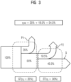
- FIG. 3 An example of a scheme of an energy conversion efficiency of a combined-cycle (cc) power plant is shown in the flowchart of Figure 3 .
- the combined cycle operation allows to increase the overall efficiency ⁇ (cc) by roughly 20% to 55% or more, such as 60% in total. This is owed to the conversion of excess heat Q of the gas turbine GT into electric power in the subsequent steam cycle of the steam turbine ST being is coupled to the gas turbine system.
- a steam turbine ST may have an individual energy conversion efficiency (from thermal to mechanical energy) of 30%. That one mechanical or electrical power which directly results from the gas turbine operation is denoted by numeral P1, whereas that one conversion which can be ascribed to the steam turbine cycle is denoted by numeral P2.
- an SOFC is known to be operated at temperatures between 800 and 1000° C, wherein the maximum temperature reached of the hot gas for simple cycle gas turbine is approximately 1500° C.
- an SOFC has usually an efficiency of between 50% and 65% and excels in very low flue emissions as compared to a gas turbine.
- Figure 4 schematically indicates (on the left) an SOFCs "cycle" indicating an energy conversion efficiency of approximately 50%.
- the presented solutions may be further used for new designed power plants as well as retrofits for existing simple and/or combined-cycle power plants to significantly increase efficiency.
- FIG. 5 indicates a power plant system 100 in a schematic connection scheme showing the system in a combined cycle operation, i.e. coupled with a solid oxide fuel cell in a load operation.
- a solid oxide fuel cell 1 in such an SOFC mode is shown.
- Said fuel cell comprises a supply for air L as well as a supply for a fuel F, such as hydrogen.
- said fuel cell is capable of providing an electrical power P or Pel which can be used for power generation purposes in general (cf. upper left part of Figure 5 ).
- Said power output may be converted beforehand, such as by a DC/AC converter 2.
- a heat exchanger to preheat a fuel for the SOFC is indicated by numeral 3.
- numeral 4 indicates a heat exchanger setup to preheat compressed air of or for the SOFC 1.
- Said gas turbine GT further expediently comprises a compressor 5 and a turbine section 7. Expediently said gas turbine GT is capable of performing the known Joule cycle jc.
- a mixture of a (remaining) fuel F or flue gas G arises which has an elevated temperature level and is therefore beneficial to be provided to the combustion chamber 6 of the gas turbine GT.
- the combustion chamber 6 may as shown also be integrated or coupled to a cooling cycle, involving the compressor 5 as well, and a fuel supply as shown in the upper left part of Figure 5 .
- the plant system 100 may be coupled to the fuel or hydrogen storage which may include an according dryer in order to provide said hydrogen to the fuel cell 1 and potentially also to the combustion chamber 6 of the gas turbine GT as a combustion gas.
- a water or H2O supply storage is shown which may be coupled to the cooling cycle of the gas turbine GT.
- gas turbine GT may be coupled in another manner to the SOFC, namely in that a compressed (charge) air Lc may be provided to the fuel cell 1 as supply in order to operate the cell in a pressurised modus, wherein particularly the cell efficiency can be increased.
- a compressed (charge) air Lc may be provided to the fuel cell 1 as supply in order to operate the cell in a pressurised modus, wherein particularly the cell efficiency can be increased.
- the arrows as shown in the connection schemes of Figure 5 and 7 shall mainly illustrate thermal couplings, flow of fuid media and/or the thermal level of fluidic or procedural connections between the different elements of the plant 100.
- thermal "couplings” relate to an idle or "off"-mode, a temperature level of below 100° C, further temperature level of between 100 and 500° C, still further temperature level of between 500 and 800° C and finally a temperature level of above 800° C.
- an according (coupled) steam cycle of the according power plant system 100 is shown.
- this cycle makes use of a steam turbine ST, expediently capable of conducting a so-called water steam cycle wsc.
- a flue gas G of the gas turbine is fed to a (heat recovery) steam generator 8 of the steam turbine system ST.
- the steam generator 8 produces, in turn, a flue gas G which may be discharged.
- accumulated water H 2 O may be provided to a condenser 10 and, then, via a (feed) water pump to the steam generator 8 in order to close the according cycle.
- a (feed) water pump to the steam generator 8 in order to close the according cycle.
- the cycle as well as the implementation of the given plant system may correspond to the flow charts as shown in Figure 4 .
- Figure 6 indicates on the left side substantially a device as already described by way of Figure 1 .
- SOEC electrolysis or regenerative mode
- the SOFC cell may be referred to as a solid oxide electrolyzer cell (SOEC).
- SOEC solid oxide electrolyzer cell
- the SOFC is a solid oxide fuel cell "hardware" run in the regenerative mode to achieve e.g. the electrolysis of water (and/or carbon dioxide) by using the solid oxide electrolyte E to produce hydrogen gas (and/or carbon monoxide) and oxygen.
- Electrolysis is an advantageous method for hydrogen production from water due to the high efficiency of conversion and relatively low required energy input when compared to thermochemical and photocatalytic methods.
- Solid oxide electrolyzer cells operate at temperatures which allow high-temperature electrolysis to occur, such as between 600 °C and 800 °C. These operating temperatures are similar or at least close to those conditions at which an SOFC operates in the cell mode.
- Figure 7 indicates the plant system 100 as well as the according inventive method of operation, wherein the SOFC is operated in an SOEC, as described above.
- the plant system 100 is operated such that the SOFC 1 operates in the regenerative (electrolysis) mode.
- the SOFC 1 has a regular cell operation.
- this mode advantageously allows for the depletion or consumption of excess grid energy (cf. P) - such as from renewable energy sources - to provide for the hydrogen and/or oxygen supply which may be further processed into fuels or other products, e.g. for chemical industry.
- the SOFC may as well be operated in a pressurised mode such as when there's a fluidic connection to the charge air of the compressor 5 of the gas turbine GT.
- the procedural circuitry of the fuel cell and an according use or depletion of excess grid energy may lead to an electrolysis or electrolytic reduction of water and/or carbon dioxide into hydrogen and a synthesis gas.
- a so-called Sabatier process can be applied as well, wherein methane may be generated from the synthesis gas.
- the loss heat from said Sabatier process may then be further used for thermal regulation of the fuel cell in an according electrolysis mode (cf. below).
- RWGS reverse water gas shift reaction
- CO 2 + H 2 -> CH 4 + CO + H 2 O a so-called reverse water gas shift reaction
- carbon dioxide can be reduced or, in other words, carbon dioxide may be reformed with hydrogen to carbon monoxide and water.
- auxiliary power units APU
- emergency power sector coupling or others is possible by the supply of the according fuel as well as consumer appliances being based on the same technology.
- the presented approach is generally broadly applicable due to the possibility of a modular architecture and exploitation of the possibility of the SOFC to be operated at partial loads.
Landscapes
- Engineering & Computer Science (AREA)
- Chemical & Material Sciences (AREA)
- Chemical Kinetics & Catalysis (AREA)
- Electrochemistry (AREA)
- Combustion & Propulsion (AREA)
- Mechanical Engineering (AREA)
- General Engineering & Computer Science (AREA)
- Metallurgy (AREA)
- Organic Chemistry (AREA)
- Materials Engineering (AREA)
- Sustainable Development (AREA)
- Life Sciences & Earth Sciences (AREA)
- General Chemical & Material Sciences (AREA)
- Inorganic Chemistry (AREA)
- Sustainable Energy (AREA)
- Manufacturing & Machinery (AREA)
- Fuel Cell (AREA)
Description
- The present invention relates to a power plant system comprising a gas turbine and a solid oxide fuel cell being coupled to said gas turbine. The solid oxide fuel cell can e.g. be operated in a load or cell mode as well as in an electrolysis mode. In other words, the solid oxide fuel cell is expediently set up to run as well in a regenerated mode, such as in order to perform water and/or carbon dioxide electrolysis.
- Further, the invention relates to a method of operating said power plant system.
- Solid oxide fuel cell (SOFC) systems are e.g. known from
patent EP 2 956 981 B1 , wherein an operational mode of said fuel cell as well as an application in energy storage is described. - The general function of an SOFC or as the case may be an SOEC (Solid Oxide Electrolyser Cell), i.e. an SOFC operated in the regenerative mode, wherein e.g. water, such as in the form of steam, is split into pure H2 and O2 as will be described further below.
- Challenges in nowadays energy landscape and related technology development concern flexibilization of energy supply, climate change implications, like the demand of decarbonization, and the need to increase efficiency of power plants and to replace fossil energy sources by renewable ones.
- In terms of decentralization there is the need to replace big or centralized grids by smaller or self-sufficient grids. The so-called sector coupling or related technology can e.g. be used to establish a connection between mobility, industry and energy sectors.
- Further, a storage of large amounts of renewable energy is required to enable a reliable energy supply in the future energy landscape to cope with inherent fluctuations in (decentralized) power generation.
- A major role in order to approach the given challenges, thus, play Power-to-X solutions and decentralised or micro-energy grids. So-called Power-to-X solutions and related energy conversion or transformation constitute key technologies for the society's future energy landscape. Thereby, flexibility in using different fuels as well as increased efficiency lead to a decrease in CO2 emissions in view of the generated electrical power. The possibility to chemically reduce e.g. carbon dioxide and water into synthesis gas (syngas) e.g. opens up the possibility for a closed energy cycle without emitting unneeded emissions like carbon dioxide CO2. In this regard there is the demand of scalability in order to enable yet a broader field of application from decentralized microgrids up to grids of the macro or industrial scale.
- As energy generation, e.g. photovoltaics, wind power or conventional or fossil resources exist, wherein only the fossil resources thereof provide for a constant (non-fluctuating) energy. In order to apply such an energy supply in the mobility sector, industry or further energy conversion, said energy may - once provided - be stored or converted in the form of hydrogen, such as provided by electrolysis, like a PEM electrolysis or other approaches. Moreover, these resources can be used for methane or carbon dioxide production.
- Solid oxide fuel cells (SOFC's) e.g. as well feature e.g. capability of oxidizing carbon and hydrogen to carbon dioxide and water by generation of or providing electrical energy. This may relate or mean a direct conversion of chemical energy to electrical energy. Regularly, SOFCs comprise an electrolyte of a solid oxide ceramic, e.g. of or comprising zirconium and/or yttrium dioxide, or Zr(Y)O2 and anode gases, such as hydrogen, methane, natural gas or coal gas. Further, SOFCs have operating temperatures of roughly between 800°C and 1000°C.
- An efficiency, such as an energy conversion or power generation efficiency of an SOFC system may amount to 50% in an SOFC mode of operation. A further advantage of an SOFC as applied in the presented solution is inter alia that no reforming of fuels is required anymore.
- In
US 2003/0054210 A1 a fuel cell generator apparatus is described comprising at least one fuel cell assembly module containing a plurality of fuel cells, each fuel cell having an electrolyte between an air electrode and a fuel electrode, a module housing enclosing the module, a pressure vessel having two ends surrounding the module housing, such that there is an air accumulation space between the module housing and the pressure vessel, wherein the pressure vessel has a fuel gas inlet tubing connecting to a module fuel gas inlet and inter alia - an air compressor associated with a gas turbine generator system for supplying compressed air. - A prior art power plant system is known from document
US5413879A . - An object of the present invention is to provide an improved solution for the given technical issues as listed in. This object is achieved by the subject-matters of the independent claims. Advantageous embodiments are subject-matter of the dependent claims.
- An aspect of the present invention relates to a power plant system comprising a solid oxide fuel cell and a gas turbine, wherein the fuel cell and the gas turbine are set up or functionally coupled such that compressed charge air of a compressor of the gas turbine can be provided to the fuel cell and/or an exhaust gas of the fuel cell can be provided to a combustion chamber of the gas turbine, wherein the system is configured such that the solid oxide fuel cell can be operated in a load or cell mode as well as in an electrolysis mode and, wherein the solid oxide fuel cell is set up such that an excess grid energy is used for executing an electrolysis in the electrolysis mode of the fuel cell and thereby to chemically reduce e.g. water and/or carbon dioxide into hydrogen and/or syngas.
- As an advantage of the solution presented herein, a solid oxide fuel cell and gas turbine interaction or combination particularly feature the possibility to reduce start-up time of the associated gas turbine, e.g. to compensate parts of the start-up operation by the functional coupling of the SOFC and the presented solutions. As a synergetic effect, an elevated temperature level - as is required for an efficient SOFC operation - may be inherently provided by the functional coupling of the gas turbine in the presented setup.
- Moreover, by the presented means, a fuel cell efficiency can be increased when operated at conditions or pressures of the gas turbine compressor discharge level.
- Moreover, unburned fuel in an exhaust gas of the fuel cell can advantageously be used for energy generation in the gas turbine combustion cycle, and therewith contribute to the working fluid.
- Therewith, in addition, the presented solution allows for compensating of grid fluctuations at high efficiency. Furthermore, there is the potential to compensate for scaling effects of gas turbines by combining this technology with that one of solid oxide fuel cells. Particularly, a loss in gas turbine efficiency at a small scale may advantageously be compensated for by the fuel cell operation in the presented "hybrid" system and therewith a "stabilization" element of micro grids is presented.
- In an embodiment, the power plant system comprises a steam turbine or steam turbine unit being functionally coupled to the gas turbine such that a "combined-cycle" plant operation is facilitated. Particularly, the presented solution is applicable to these combined cycle approaches so that the efficiency benefit of combined-cycle power plants can be exploited, and an according overall efficiency increase be achieved.
- An increase of the electrical efficiency of up to 10% by a combination of an energy conversion concept applying thermodynamic cycles and as well galvanic principles is particularly possible including exploitation of heat of a turbo machine, such as a gas turbine.
- A further aspect of the present invention relates to a method of operating a power plant system as described above. In this method, the solid oxide fuel cell is operated in a load or cell mode or, alternatively, in an electrolysis mode or regenerated mode. Consequently, the presented plant system can be operated in a versatile way and in both operating modes. Therewith, the system is adapted to the mentioned demands in the energy supply landscape and can, thus, provide for the mentioned advantages and cope with the demands of grid flexibilisation and decarbonisation.
- Particularly, the field of application of conventional gas turbine technology in terms of efficiency, field of operation and emissions is increased at all scales by the presented approach. For instance, a low efficiency of small (industrial) gas turbines and compensation of the inertness of large (power plant) gas turbines may be compensated for by the integration of the fuel cell technology as described herein. In other words a combination of an electricity generating technology and fuel generating technology may be achieved. Due to the good scalability, furthermore an implementation on a decentralised scale as well as in a macro-industrial scale is possible.
- Specifically, the regenerative mode of the fuel cell allows for an efficient electrolytic reduction of carbon dioxide and/or water and therewith to provide for a Power-to-X solutions along with its merits.
- Z P According to the claimed invention, an excess grid energy is used for executing an electrolysis in the electrolysis mode of the fuel cell and thereby to chemically reduce water and/or carbon dioxide into hydrogen and syngas. As an advantage thereof, on one side superfluous grid energy can be taken off or consumed. Also, such energy can be used in a sustainable way to provide fuels or other (hydro-carbon-based) products, such as for storage applications and/or further industrial application.
- In an embodiment the solid oxide fuel cell is operated in an ambient of compressed charge air being generated by a compressor of the gas turbine. In this way, the above-mentioned advantages can be exploited.
- A compressor of a gas turbine allows to provide a charging pressure to the fuel cell during load and electrolysis operation in order to increase performance. Exhaust or flue gases of the fuel cell may in addition be expanded in the turbine section in order to reduce the necessary driving power of the compressor (via the generator) or - in case of excess energy - to use this for an increased electrolysis yield. By the use of a reversible operating fuel cell which is integrated into conventional power plant technology, said plant may convert chemical energy into electric energy. Further, an excess of electrical energy can be advantageously converted into chemical energy in form of the according fuels. This provides for significant synergy effects and progress in the development of the related technological fields.
- In an embodiment, an exhaust gas of the fuel cell still containing a fuel is provided to the combustion chamber of the gas turbine. In this way, the above-mentioned advantages can be exploited. In other words, this provides for an advantageous reduction of the necessary drive capacity of the compressor, such as via the generator or - in the case of excess grid energy - to use the same for an increased electrolysis yield.
- In an embodiment, the method comprises a Sabatier reaction to be applied to the syngas in order to provide methane. Said methane can, of course, lateron be further used as a fuel gas or applied for other purposes.
- In an embodiment, waste or excess heat from the Sabatier reaction is used for thermally regulating the solid oxide fuel cell in the relevant service mode. The term "regulating" may mean that said exotermic reaction can advantageously provide for heat necessary to allow for the fuel cell to operate at an expedient thermal level.
- Advantages and embodiments relating to the described plant system may as well pertain or be valid with regard to the according method of operation as described.
- Further features, expediencies and advantageous embodiments become apparent from the following description of the exemplary embodiments in connection with the Figures.
-
Figure 1 indicates in a schematic basic functional principle is of a solid oxide fuel cell. -
Figure 2 indicates in a schematic flow chart an energy conversion efficiency level of a gas turbine in a simple cycle. -
Figure 3 indicates in a schematic flow chart an energy conversion efficiency level of a gas turbine in a combined cycle operation involving a steam turbine unit. -
Figure 4 indicates in a schematic flow chart energy conversion efficiency levels of a solid oxide fuel cell and, subsequently, a gas turbine, in a combined cycle mode as according to an embodiment of the present invention. -
Figure 5 indicates a schematic connection scheme of a combined cycle power plant coupled with a solid oxide fuel cell system in a load operation. -
Figure 6 schematically opposes a scheme of a solid oxide fuel cell in a load or cell mode (left) and an according solid oxide fuel cell in an electrolysis or regenerative mode (right). -
Figure 7 indicates a schematic connection scheme of a combined cycle power plant coupled with a solid oxide fuel cell system in an electrolysis mode. -
Figure 8 indicates a schematic flow chart energy conversion efficiency levels of a solid oxide fuel cell and, subsequently, a gas turbine in a simple cycle. - Like elements, elements of the same kind and identically acting elements may be provided with the same reference numerals in the Figures. The Figures are not necessarily depicted true to scale and may be scaled up or down to allow for a better understanding of the illustrated principles. Rather, the described Figures are to be construed in a broad sense and as a qualitative base which allows a person skilled in the art to apply the presented teaching in a versatile way.
- The term "and/or" as used herein shall mean that each of the listed elements may be taken alone or in conjunction with two or more of further listed elements.
-
Figure 1 indicates the basic functional principle of a solid oxide fuel cell (SOFC), inter alia indicating the general building blocks of an SOFC and a fuel, such as hydrogen, and an air supply. - Fuel cells in general are distinguished by their electrolyte material E. The solid oxide cells feature solid oxide or ceramic electrolytes. Advantages of such fuel cells include a high heat and power efficiency, long-term durability and fuel versatility. As well, there is a relatively low cost at only very poor or negligible environmental and flue emissions. A supposed disadvantage is the high operating temperature which results in longer start-up times and mechanical and chemical compatibility issues. This requirement may, however, be turned into an advantage when contemplating the principles of the present invention. The electrochemical oxidation of hydrogen (H2) as shown in
Figure 1 or carbon monoxide or other organic intermediates (not explicitly shown in the Figures) by oxygen ions, thus, occurs on the anode side. - Usually SOFCs operate at relatively high temperatures, typically between 500 and 1000 °C. At these thermal levels, expensive catalyst material may advantageously be dispensed with, whereas such catalysts may be necessary for lower temperature fuel cells such as PEMFCs (Proton Exchange Membrane Fuel Cells).
- A solid oxide fuel cell is a galvanic or an electrochemical conversion device that produces electricity (cf. numeral P for electrical power) directly from oxidizing a fuel F, such as hydrogen. Moreover oxygen, such as in form of air L has to be supplied. Then, oxygen ions are generated at a cathode K and conducted via the electrolyte E to the anode A as shown in
Figure 1 . The supplied air itself is reduced and thus air L' with a decreased oxygen percentage is discharged. -
Figure 2 indicates a schematic flow chart of a gas turbine's energy conversion efficiency. At the bottom it is indicated that said conversion efficiency η (from thermal to mechanical energy) of conventional gas turbines amounts to about 35%. Consequently roughly 35% of mechanical or electrical power P can be consumed, such as for power generation purposes. A remainder of 65% of the energy dissipates in form of heat Q. - An example of a scheme of an energy conversion efficiency of a combined-cycle (cc) power plant is shown in the flowchart of
Figure 3 . As compared to the situation as shown inFigure 2 , the combined cycle operation allows to increase the overall efficiency η(cc) by roughly 20% to 55% or more, such as 60% in total. This is owed to the conversion of excess heat Q of the gas turbine GT into electric power in the subsequent steam cycle of the steam turbine ST being is coupled to the gas turbine system. It is further apparent that a steam turbine ST may have an individual energy conversion efficiency (from thermal to mechanical energy) of 30%. That one mechanical or electrical power which directly results from the gas turbine operation is denoted by numeral P1, whereas that one conversion which can be ascribed to the steam turbine cycle is denoted by numeral P2. - The present invention now seeks to combine the operation of a solid oxide fuel cell, be it in a cell or electrolysis mode, to be combined with one of the mentioned power plant cycles. Generally, an SOFC is known to be operated at temperatures between 800 and 1000° C, wherein the maximum temperature reached of the hot gas for simple cycle gas turbine is approximately 1500° C. As compared to the conversion efficiency of the gas turbine, an SOFC has usually an efficiency of between 50% and 65% and excels in very low flue emissions as compared to a gas turbine.
- A start-up time of a solid oxide fuel cell is further high as compared to a fairly low and advantageous start-up time of the gas turbine. On the contrary, of course emissions of an SOFC are advantageously low as compared to the medium to high emissions of the gas turbine.
- By cascading an energy conversion chain in a combined-cycle power plant operation, efficiency can be increased. However, technically, an upper limit of electrical efficiency is foreseeable at around 65%. Probably, efficiencies of conventional plant technology development will converge to this value. A reason for that may be the restriction to Carnot's efficiency as well as the advanced level of development of the underlying technology.
- As compared to
Figures 2 and3 ,Figure 4 schematically indicates (on the left) an SOFCs "cycle" indicating an energy conversion efficiency of approximately 50%. - With regard to the fuel cell cycle, an electrical power P1 is supplied by the SOFC (cf. also reference numeral 1 below). Around half of the output, i.e. roughly 25 % is heat Q which is further processed in the combined cycle modus. In other words, the (waste) heat of the fuel cell is provided to a gas turbine cycle, such as in that an exhaust flue gas of the fuel cell is provided to a combustion chamber (cf. reference numeral 6 further below) of the gas turbine GT. In turn, said gas turbine cycle may, as indicated (analogue to the indication of
Figure 3 ) well be coupled to a further steam turbine cycle. This can lead in total to an increased overall energy conversion efficiency of η (SOFC cc) of P1≈25% + P2≈26% + P3=14% which equals to around 66% at this stage already. Apparently, a significant increase in energy conversion efficiency is possible in the described way, wherein at the same time further advantages of the present invention may be exploited (cf. as wellFigures 7 and8 below). For instance, the technical advantages of the described "triple"-cycle concept relate to a significantly increased efficiency in an operational SOFC mode, like an increase of 10% to 15%. Further, a lower emission per megawatt by the quasi "cold combustion" process of the SOFC may be achieved. The presented principle stand out for its scalability and its ability to be applied in decentralized grid applications and e.g. for so-called auxiliary power units and in areas with insufficient grid support. - The presented solutions may be further used for new designed power plants as well as retrofits for existing simple and/or combined-cycle power plants to significantly increase efficiency.
-
Figure 5 indicates apower plant system 100 in a schematic connection scheme showing the system in a combined cycle operation, i.e. coupled with a solid oxide fuel cell in a load operation. On the left, a solid oxide fuel cell 1 in such an SOFC mode is shown. Said fuel cell comprises a supply for air L as well as a supply for a fuel F, such as hydrogen. According to the known principle, said fuel cell is capable of providing an electrical power P or Pel which can be used for power generation purposes in general (cf. upper left part ofFigure 5 ). Said power output may be converted beforehand, such as by a DC/AC converter 2. A heat exchanger to preheat a fuel for the SOFC is indicated bynumeral 3. Moreover, numeral 4 indicates a heat exchanger setup to preheat compressed air of or for the SOFC 1. - Due to the elevated temperature operation of the fuel cell (cf. above), there is a hot air exhaust of the fuel cell operation which may be provided (fluidly coupled via a valve which is not explicitly indicated) to the combustion chamber 6 of a gas turbine GT. Said gas turbine GT further expediently comprises a
compressor 5 and a turbine section 7. Expediently said gas turbine GT is capable of performing the known Joule cycle jc. - Likewise, a mixture of a (remaining) fuel F or flue gas G arises which has an elevated temperature level and is therefore beneficial to be provided to the combustion chamber 6 of the gas turbine GT.
- The combustion chamber 6 may as shown also be integrated or coupled to a cooling cycle, involving the
compressor 5 as well, and a fuel supply as shown in the upper left part ofFigure 5 . By the according boxes it shall be indicated e.g. that theplant system 100 may be coupled to the fuel or hydrogen storage which may include an according dryer in order to provide said hydrogen to the fuel cell 1 and potentially also to the combustion chamber 6 of the gas turbine GT as a combustion gas. Moreover, further to the right in the upper part ofFigure 5 , a water or H2O supply storage is shown which may be coupled to the cooling cycle of the gas turbine GT. - In addition, the gas turbine GT may be coupled in another manner to the SOFC, namely in that a compressed (charge) air Lc may be provided to the fuel cell 1 as supply in order to operate the cell in a pressurised modus, wherein particularly the cell efficiency can be increased.
- The arrows as shown in the connection schemes of
Figure 5 and7 shall mainly illustrate thermal couplings, flow of fuid media and/or the thermal level of fluidic or procedural connections between the different elements of theplant 100. For further particulars it is referred to the according legend of symbols, indicating that the respective thermal "couplings" relate to an idle or "off"-mode, a temperature level of below 100° C, further temperature level of between 100 and 500° C, still further temperature level of between 500 and 800° C and finally a temperature level of above 800° C. - Additionally, on the right side of
Figure 5 , an according (coupled) steam cycle of the accordingpower plant system 100 is shown. As introduced above, this cycle makes use of a steam turbine ST, expediently capable of conducting a so-called water steam cycle wsc. - As shown at the bottom of
Figure 5 , a flue gas G of the gas turbine is fed to a (heat recovery)steam generator 8 of the steam turbine system ST. In a downward flow, thesteam generator 8 produces, in turn, a flue gas G which may be discharged. - A steam St generated by the
steam generator 8 is moreover provided to thesteam turbine section 9 in order to produce an according output of mechanical or electrical power P. - At the downward end of the
steam turbine section 9, accumulated water H2O may be provided to acondenser 10 and, then, via a (feed) water pump to thesteam generator 8 in order to close the according cycle. Particularly the cycle as well as the implementation of the given plant system may correspond to the flow charts as shown inFigure 4 . -
Figure 6 indicates on the left side substantially a device as already described by way ofFigure 1 . On the right part of the picture, however, the function of an SOFC in the electrolysis or regenerative mode (SOEC) is opposed, wherein e.g. water, such as in the form of steam, is split into pure H2 (hydrogen) and O2 (Oxygen). In this modus, the SOFC cell may be referred to as a solid oxide electrolyzer cell (SOEC). In other words, the SOFC is a solid oxide fuel cell "hardware" run in the regenerative mode to achieve e.g. the electrolysis of water (and/or carbon dioxide) by using the solid oxide electrolyte E to produce hydrogen gas (and/or carbon monoxide) and oxygen. - When a voltage is applied to the device, water vapour moves to the electrolyte interface and is reduced to form pure H2 and oxygen ions. The hydrogen gas may then be collected at its surface as hydrogen fuel. In turn, the oxygen ions are conducted through the electrolyte E. At the other electrolyte interface, oxygen ions are oxidized to form pure oxygen gas or air L' with an increased portion of oxygen, which may be collected at the surface (on the right in
Figure 6 ). - Apparently, the production of pure hydrogen is required as it can be obtained as clean (green) fuel that can in turn constitute a storage medium, thus providing a potential alternative to batteries, which have in contrast a low storage capacity and create high amounts of waste material. Electrolysis is an advantageous method for hydrogen production from water due to the high efficiency of conversion and relatively low required energy input when compared to thermochemical and photocatalytic methods.
- Solid oxide electrolyzer cells operate at temperatures which allow high-temperature electrolysis to occur, such as between 600 °C and 800 °C. These operating temperatures are similar or at least close to those conditions at which an SOFC operates in the cell mode.
-
Figure 7 indicates theplant system 100 as well as the according inventive method of operation, wherein the SOFC is operated in an SOEC, as described above. In contrast to the situation as shown inFigure 5 , theplant system 100 is operated such that the SOFC 1 operates in the regenerative (electrolysis) mode. In this situation, basic procedural principles as well apply as in the case in which the SOFC 1 has a regular cell operation. Particularly this mode advantageously allows for the depletion or consumption of excess grid energy (cf. P) - such as from renewable energy sources - to provide for the hydrogen and/or oxygen supply which may be further processed into fuels or other products, e.g. for chemical industry. Additionally, the SOFC may as well be operated in a pressurised mode such as when there's a fluidic connection to the charge air of thecompressor 5 of the gas turbine GT. - Even though this embodiment may not be explicitly indicated in
Figure 7 , the procedural circuitry of the fuel cell and an according use or depletion of excess grid energy may lead to an electrolysis or electrolytic reduction of water and/or carbon dioxide into hydrogen and a synthesis gas. Thereby a so-called Sabatier process can be applied as well, wherein methane may be generated from the synthesis gas. The loss heat from said Sabatier process may then be further used for thermal regulation of the fuel cell in an according electrolysis mode (cf. below). - In addition, or alternative to said Sabatier process, a so-called reverse water gas shift reaction (RWGS), like CO2 + H2 -> CH4 + CO + H2O, maybe applied. As an advantage thereof, carbon dioxide can be reduced or, in other words, carbon dioxide may be reformed with hydrogen to carbon monoxide and water.
-
Figure 8 illustrates - analogue toFigure 4 that - other than suggested inFigures 5 and7 - the presentpower plant system 100 may as well be set up without a combined steam cycle, i.e. in a simple cycle sc. An according energy conversion efficiency is schematically indicated, wherein only the SOFC in its fuel cell mode and a gas turbine GT are coupled. Besides the accumulated heat Q, it is apparent that an electrical power output P1 is yielded from the SOFC operation. As described above, P1 amounts roughly to half of the overall output power of the SOFC. As well, an output power P2 is yielded from the gas turbine GT operation, whereas the remainder is discharged as heat Q. When adding up P1 and P2 or as the case may be the underlying conversion efficiencies one obtains an overall efficiency of η (SOFC GT) of P1≈50% + P2≈12% which equals to around 63%. - Aside from a possible stationary operation, also a mobile application, as for instance in marine propulsion, wherein the generated fuels may be used to a larger extent, or in so-called auxiliary power units (APU), for marine and aeroflight applications, emergency power, sector coupling or others is possible by the supply of the according fuel as well as consumer appliances being based on the same technology.
- The presented approach is generally broadly applicable due to the possibility of a modular architecture and exploitation of the possibility of the SOFC to be operated at partial loads.
Claims (9)
- Power plant system (100) comprising a solid oxide fuel cell (1, SOFC) and a gas turbine (GT), wherein the fuel cell (1) and the gas turbine are set up such that compressed charge air (Lc) of a compressor (5) of the gas turbine (GT) can be provided to the fuel cell (1) and/or an exhaust gas (G) of the fuel cell (1) can be provided to a combustion chamber (6) of the gas turbine (GT), wherein the system (100) is configured such that the solid oxide fuel cell (1) can be operated in a load or cell mode, the system (100) being characterized in that the solid oxide fuel cell (1) can as well be operated in an electrolysis mode and in that the solid oxide fuel cell (SOFC) is set up such that an excess grid energy is used for executing an electrolysis in the electrolysis mode of the fuel cell (1) and thereby to chemically reduce water (H2O) and/or carbon dioxide into hydrogen (H2) and/or syngas.
- Power plant system (100) as claimed in claim 1, further comprising a steam turbine (ST) being functionally coupled to the gas turbine (GT) such that a combined-cycle plant operation (cc) is facilitated.
- Method of operating a power plant system (100) as claimed in claim 1 or 2, wherein the solid oxide fuel cell (1) is operated in a load or a cell mode (SOFC).
- Method of operating a power plant system (100) as claimed in one of claims 1 to 2, wherein the solid oxide fuel cell (1) is operated in an electrolysis mode (SOEC).
- Method of operating a power plant system (100) as claimed in claim 3 or 4, wherein an excess grid energy is used for executing an electrolysis in the electrolysis mode of the fuel cell (1) and thereby to chemically reduce water (H2O) and/or carbon dioxide into hydrogen (H2) and syngas.
- Method of operating a power plant system as claimed in claim 5, wherein the solid oxide fuel cell (1) is operated in an ambient of compressed charge air (Lc) being generated by the compressor (5) of the gas turbine (GT).
- Method of operating a power plant system (100) as claimed in one of claims 3 to 6, wherein an exhaust gas of the fuel cell (1) still containing a fuel (F) is provided to the combustion chamber (6) of the gas turbine (GT).
- Method of operating a power plant system (100) as claimed in one of claims 4 to 7, wherein a Sabatier reaction is applied to the syngas in order to provide methane.
- Method of operating a power plant system (100) as claimed in claim 8, wherein waste heat (Q) from the Sabatier reaction is used for thermally regulating the fuel cell (1).
Applications Claiming Priority (2)
| Application Number | Priority Date | Filing Date | Title |
|---|---|---|---|
| EP19205050 | 2019-10-24 | ||
| PCT/EP2020/079844 WO2021078919A1 (en) | 2019-10-24 | 2020-10-23 | Power plant system and method of operating the same |
Publications (3)
| Publication Number | Publication Date |
|---|---|
| EP3997318A1 EP3997318A1 (en) | 2022-05-18 |
| EP3997318B1 true EP3997318B1 (en) | 2024-07-03 |
| EP3997318C0 EP3997318C0 (en) | 2024-07-03 |
Family
ID=68581134
Family Applications (1)
| Application Number | Title | Priority Date | Filing Date |
|---|---|---|---|
| EP20804446.1A Active EP3997318B1 (en) | 2019-10-24 | 2020-10-23 | Power plant system and method of operating the same |
Country Status (4)
| Country | Link |
|---|---|
| US (1) | US12291994B2 (en) |
| EP (1) | EP3997318B1 (en) |
| ES (1) | ES2988116T3 (en) |
| WO (1) | WO2021078919A1 (en) |
Families Citing this family (6)
| Publication number | Priority date | Publication date | Assignee | Title |
|---|---|---|---|---|
| US12567595B2 (en) | 2022-11-10 | 2026-03-03 | General Electric Company | Gas turbine combustion section having an integrated fuel cell assembly |
| US12078350B2 (en) | 2022-11-10 | 2024-09-03 | General Electric Company | Gas turbine combustion section having an integrated fuel cell assembly |
| US12240613B2 (en) | 2022-11-10 | 2025-03-04 | General Electric Company | Gas turbine combustion section having an integrated fuel cell assembly |
| US11923586B1 (en) * | 2022-11-10 | 2024-03-05 | General Electric Company | Gas turbine combustion section having an integrated fuel cell assembly |
| US20240106269A1 (en) * | 2023-08-02 | 2024-03-28 | Peter Kaminsky | Method of Unlimited Direct Use Of Excess Energy, Generated During Off-Peak Consumption Of The Electrical Network |
| CN119508062B (en) * | 2024-11-07 | 2025-09-16 | 北京腾达绿氢能科技有限公司 | A gas-fired power generation system and power generation method utilizing efficient coupling of renewable energy |
Family Cites Families (7)
| Publication number | Priority date | Publication date | Assignee | Title |
|---|---|---|---|---|
| US5413879A (en) | 1994-02-08 | 1995-05-09 | Westinghouse Electric Corporation | Integrated gas turbine solid oxide fuel cell system |
| US5955039A (en) | 1996-12-19 | 1999-09-21 | Siemens Westinghouse Power Corporation | Coal gasification and hydrogen production system and method |
| US7045238B2 (en) * | 2003-03-24 | 2006-05-16 | Ion America Corporation | SORFC power and oxygen generation method and system |
| US7364810B2 (en) | 2003-09-03 | 2008-04-29 | Bloom Energy Corporation | Combined energy storage and fuel generation with reversible fuel cells |
| GB0524486D0 (en) * | 2005-12-01 | 2006-01-11 | Rolls Royce Fuel Cell Systems | An electrolysis apparatus |
| DE102013205407A1 (en) | 2013-03-27 | 2014-10-16 | Siemens Aktiengesellschaft | Energy converter cell with electrochemical converter unit |
| JP6945315B2 (en) * | 2017-03-24 | 2021-10-06 | 三菱重工業株式会社 | Power plant and how to operate the power plant |
-
2020
- 2020-10-23 WO PCT/EP2020/079844 patent/WO2021078919A1/en not_active Ceased
- 2020-10-23 ES ES20804446T patent/ES2988116T3/en active Active
- 2020-10-23 EP EP20804446.1A patent/EP3997318B1/en active Active
- 2020-10-23 US US17/769,401 patent/US12291994B2/en active Active
Also Published As
| Publication number | Publication date |
|---|---|
| EP3997318A1 (en) | 2022-05-18 |
| US12291994B2 (en) | 2025-05-06 |
| ES2988116T3 (en) | 2024-11-19 |
| WO2021078919A1 (en) | 2021-04-29 |
| EP3997318C0 (en) | 2024-07-03 |
| US20240125269A1 (en) | 2024-04-18 |
Similar Documents
| Publication | Publication Date | Title |
|---|---|---|
| EP3997318B1 (en) | Power plant system and method of operating the same | |
| CA3028495C (en) | Process for starting mode or stand-by mode operation of a power-to-gas unit comprising a plurality of high-temperature electrolysis (soec) or co-electrolysis reactors | |
| Ellamla et al. | Current status of fuel cell based combined heat and power systems for residential sector | |
| EP2692008B1 (en) | Solid-oxide fuel cell high-efficiency reform-and-recirculate system | |
| Lanzini et al. | Experimental investigation of direct internal reforming of biogas in solid oxide fuel cells | |
| JP5229772B2 (en) | Power generation equipment | |
| Zhang et al. | A review of integration strategies for solid oxide fuel cells | |
| US9435230B2 (en) | Fuel cell hybrid system | |
| JP6124923B2 (en) | High-temperature steam electrolysis equipment (HTSE) with externally heated hydrogen production | |
| US20160260991A1 (en) | Power generation system utilizing a fuel cell integrated with a combustion engine | |
| JP2018193612A (en) | Energy storage using REP with engine | |
| JP7359986B2 (en) | Energy storage for combustion turbines using molten carbonate electrolyzer batteries | |
| Shah | Introduction to fuel cells | |
| Xu et al. | High-temperature electrolysis and co-electrolysis | |
| US20140060461A1 (en) | Power generation system utilizing a fuel cell integrated with a combustion engine | |
| JP5294291B2 (en) | Power generation equipment | |
| JP7043288B2 (en) | Combined power generation system, combined cycle system operation switching method, and combined cycle system operation switching program | |
| Song et al. | The study on the role of reversible solid oxide cell (rSOC) in sector-coupling of energy systems | |
| KR20220145901A (en) | fuel cell power generation system | |
| US12331417B1 (en) | Methods and systems for the conversion of carbon dioxide to chemicals and/or fuels utilizing steam electrolysis | |
| US20250198016A1 (en) | Methods and systems for the electrochemical conversion of carbon dioxide and steam to syngas | |
| US20250197328A1 (en) | Methods and systems for the conversion of carbon dioxide to chemicals and/or fuels utilizing steam electrolysis | |
| KR20200123884A (en) | Solid oxide fuel cell system using ballast water treatment system | |
| Douvartzides et al. | Thermodynamic and economic analysis of a steam reformer-solid oxide fuel cell system fed by natural gas and ethanol | |
| JP2024106828A (en) | Fuel cell system and method for controlling the fuel cell system |
Legal Events
| Date | Code | Title | Description |
|---|---|---|---|
| STAA | Information on the status of an ep patent application or granted ep patent |
Free format text: STATUS: UNKNOWN |
|
| STAA | Information on the status of an ep patent application or granted ep patent |
Free format text: STATUS: THE INTERNATIONAL PUBLICATION HAS BEEN MADE |
|
| PUAI | Public reference made under article 153(3) epc to a published international application that has entered the european phase |
Free format text: ORIGINAL CODE: 0009012 |
|
| STAA | Information on the status of an ep patent application or granted ep patent |
Free format text: STATUS: REQUEST FOR EXAMINATION WAS MADE |
|
| 17P | Request for examination filed |
Effective date: 20220214 |
|
| AK | Designated contracting states |
Kind code of ref document: A1 Designated state(s): AL AT BE BG CH CY CZ DE DK EE ES FI FR GB GR HR HU IE IS IT LI LT LU LV MC MK MT NL NO PL PT RO RS SE SI SK SM TR |
|
| DAV | Request for validation of the european patent (deleted) | ||
| DAX | Request for extension of the european patent (deleted) | ||
| GRAP | Despatch of communication of intention to grant a patent |
Free format text: ORIGINAL CODE: EPIDOSNIGR1 |
|
| STAA | Information on the status of an ep patent application or granted ep patent |
Free format text: STATUS: GRANT OF PATENT IS INTENDED |
|
| INTG | Intention to grant announced |
Effective date: 20240228 |
|
| GRAS | Grant fee paid |
Free format text: ORIGINAL CODE: EPIDOSNIGR3 |
|
| GRAA | (expected) grant |
Free format text: ORIGINAL CODE: 0009210 |
|
| STAA | Information on the status of an ep patent application or granted ep patent |
Free format text: STATUS: THE PATENT HAS BEEN GRANTED |
|
| AK | Designated contracting states |
Kind code of ref document: B1 Designated state(s): AL AT BE BG CH CY CZ DE DK EE ES FI FR GB GR HR HU IE IS IT LI LT LU LV MC MK MT NL NO PL PT RO RS SE SI SK SM TR |
|
| REG | Reference to a national code |
Ref country code: CH Ref legal event code: EP |
|
| REG | Reference to a national code |
Ref country code: DE Ref legal event code: R096 Ref document number: 602020033455 Country of ref document: DE |
|
| U01 | Request for unitary effect filed |
Effective date: 20240715 |
|
| U07 | Unitary effect registered |
Designated state(s): AT BE BG DE DK EE FI FR IT LT LU LV MT NL PT SE SI Effective date: 20240726 |
|
| REG | Reference to a national code |
Ref country code: ES Ref legal event code: FG2A Ref document number: 2988116 Country of ref document: ES Kind code of ref document: T3 Effective date: 20241119 |
|
| U20 | Renewal fee for the european patent with unitary effect paid |
Year of fee payment: 5 Effective date: 20241025 |
|
| PG25 | Lapsed in a contracting state [announced via postgrant information from national office to epo] |
Ref country code: GR Free format text: LAPSE BECAUSE OF FAILURE TO SUBMIT A TRANSLATION OF THE DESCRIPTION OR TO PAY THE FEE WITHIN THE PRESCRIBED TIME-LIMIT Effective date: 20241004 Ref country code: PL Free format text: LAPSE BECAUSE OF FAILURE TO SUBMIT A TRANSLATION OF THE DESCRIPTION OR TO PAY THE FEE WITHIN THE PRESCRIBED TIME-LIMIT Effective date: 20240703 |
|
| PG25 | Lapsed in a contracting state [announced via postgrant information from national office to epo] |
Ref country code: IS Free format text: LAPSE BECAUSE OF FAILURE TO SUBMIT A TRANSLATION OF THE DESCRIPTION OR TO PAY THE FEE WITHIN THE PRESCRIBED TIME-LIMIT Effective date: 20241103 |
|
| PG25 | Lapsed in a contracting state [announced via postgrant information from national office to epo] |
Ref country code: CZ Free format text: LAPSE BECAUSE OF FAILURE TO SUBMIT A TRANSLATION OF THE DESCRIPTION OR TO PAY THE FEE WITHIN THE PRESCRIBED TIME-LIMIT Effective date: 20240703 Ref country code: HR Free format text: LAPSE BECAUSE OF FAILURE TO SUBMIT A TRANSLATION OF THE DESCRIPTION OR TO PAY THE FEE WITHIN THE PRESCRIBED TIME-LIMIT Effective date: 20240703 |
|
| PG25 | Lapsed in a contracting state [announced via postgrant information from national office to epo] |
Ref country code: RS Free format text: LAPSE BECAUSE OF FAILURE TO SUBMIT A TRANSLATION OF THE DESCRIPTION OR TO PAY THE FEE WITHIN THE PRESCRIBED TIME-LIMIT Effective date: 20241003 |
|
| PG25 | Lapsed in a contracting state [announced via postgrant information from national office to epo] |
Ref country code: RS Free format text: LAPSE BECAUSE OF FAILURE TO SUBMIT A TRANSLATION OF THE DESCRIPTION OR TO PAY THE FEE WITHIN THE PRESCRIBED TIME-LIMIT Effective date: 20241003 Ref country code: PL Free format text: LAPSE BECAUSE OF FAILURE TO SUBMIT A TRANSLATION OF THE DESCRIPTION OR TO PAY THE FEE WITHIN THE PRESCRIBED TIME-LIMIT Effective date: 20240703 Ref country code: IS Free format text: LAPSE BECAUSE OF FAILURE TO SUBMIT A TRANSLATION OF THE DESCRIPTION OR TO PAY THE FEE WITHIN THE PRESCRIBED TIME-LIMIT Effective date: 20241103 Ref country code: HR Free format text: LAPSE BECAUSE OF FAILURE TO SUBMIT A TRANSLATION OF THE DESCRIPTION OR TO PAY THE FEE WITHIN THE PRESCRIBED TIME-LIMIT Effective date: 20240703 Ref country code: GR Free format text: LAPSE BECAUSE OF FAILURE TO SUBMIT A TRANSLATION OF THE DESCRIPTION OR TO PAY THE FEE WITHIN THE PRESCRIBED TIME-LIMIT Effective date: 20241004 Ref country code: CZ Free format text: LAPSE BECAUSE OF FAILURE TO SUBMIT A TRANSLATION OF THE DESCRIPTION OR TO PAY THE FEE WITHIN THE PRESCRIBED TIME-LIMIT Effective date: 20240703 |
|
| PG25 | Lapsed in a contracting state [announced via postgrant information from national office to epo] |
Ref country code: SM Free format text: LAPSE BECAUSE OF FAILURE TO SUBMIT A TRANSLATION OF THE DESCRIPTION OR TO PAY THE FEE WITHIN THE PRESCRIBED TIME-LIMIT Effective date: 20240703 |
|
| PG25 | Lapsed in a contracting state [announced via postgrant information from national office to epo] |
Ref country code: SK Free format text: LAPSE BECAUSE OF FAILURE TO SUBMIT A TRANSLATION OF THE DESCRIPTION OR TO PAY THE FEE WITHIN THE PRESCRIBED TIME-LIMIT Effective date: 20240703 |
|
| PLBE | No opposition filed within time limit |
Free format text: ORIGINAL CODE: 0009261 |
|
| STAA | Information on the status of an ep patent application or granted ep patent |
Free format text: STATUS: NO OPPOSITION FILED WITHIN TIME LIMIT |
|
| 26N | No opposition filed |
Effective date: 20250404 |
|
| PG25 | Lapsed in a contracting state [announced via postgrant information from national office to epo] |
Ref country code: MC Free format text: LAPSE BECAUSE OF FAILURE TO SUBMIT A TRANSLATION OF THE DESCRIPTION OR TO PAY THE FEE WITHIN THE PRESCRIBED TIME-LIMIT Effective date: 20240703 |
|
| PG25 | Lapsed in a contracting state [announced via postgrant information from national office to epo] |
Ref country code: IE Free format text: LAPSE BECAUSE OF NON-PAYMENT OF DUE FEES Effective date: 20241023 |
|
| REG | Reference to a national code |
Ref country code: CH Ref legal event code: U11 Free format text: ST27 STATUS EVENT CODE: U-0-0-U10-U11 (AS PROVIDED BY THE NATIONAL OFFICE) Effective date: 20251101 |
|
| PG25 | Lapsed in a contracting state [announced via postgrant information from national office to epo] |
Ref country code: RO Free format text: LAPSE BECAUSE OF FAILURE TO SUBMIT A TRANSLATION OF THE DESCRIPTION OR TO PAY THE FEE WITHIN THE PRESCRIBED TIME-LIMIT Effective date: 20240703 |
|
| U20 | Renewal fee for the european patent with unitary effect paid |
Year of fee payment: 6 Effective date: 20251027 |
|
| PGFP | Annual fee paid to national office [announced via postgrant information from national office to epo] |
Ref country code: GB Payment date: 20251023 Year of fee payment: 6 |
|
| PGFP | Annual fee paid to national office [announced via postgrant information from national office to epo] |
Ref country code: NO Payment date: 20251022 Year of fee payment: 6 |
|
| PGFP | Annual fee paid to national office [announced via postgrant information from national office to epo] |
Ref country code: CH Payment date: 20251101 Year of fee payment: 6 |
|
| PG25 | Lapsed in a contracting state [announced via postgrant information from national office to epo] |
Ref country code: CY Free format text: LAPSE BECAUSE OF FAILURE TO SUBMIT A TRANSLATION OF THE DESCRIPTION OR TO PAY THE FEE WITHIN THE PRESCRIBED TIME-LIMIT; INVALID AB INITIO Effective date: 20201023 |
|
| PGFP | Annual fee paid to national office [announced via postgrant information from national office to epo] |
Ref country code: ES Payment date: 20251118 Year of fee payment: 6 |
|
| PG25 | Lapsed in a contracting state [announced via postgrant information from national office to epo] |
Ref country code: HU Free format text: LAPSE BECAUSE OF FAILURE TO SUBMIT A TRANSLATION OF THE DESCRIPTION OR TO PAY THE FEE WITHIN THE PRESCRIBED TIME-LIMIT; INVALID AB INITIO Effective date: 20201023 |