EP3996897B1 - Adding a segment of fiber-reinforced thermoplastic filament in a curve - Google Patents
Adding a segment of fiber-reinforced thermoplastic filament in a curve Download PDFInfo
- Publication number
- EP3996897B1 EP3996897B1 EP20737806.8A EP20737806A EP3996897B1 EP 3996897 B1 EP3996897 B1 EP 3996897B1 EP 20737806 A EP20737806 A EP 20737806A EP 3996897 B1 EP3996897 B1 EP 3996897B1
- Authority
- EP
- European Patent Office
- Prior art keywords
- wheel
- filament
- axis
- target path
- supporting structure
- Prior art date
- Legal status (The legal status is an assumption and is not a legal conclusion. Google has not performed a legal analysis and makes no representation as to the accuracy of the status listed.)
- Active
Links
Images






Classifications
-
- B—PERFORMING OPERATIONS; TRANSPORTING
- B29—WORKING OF PLASTICS; WORKING OF SUBSTANCES IN A PLASTIC STATE IN GENERAL
- B29C—SHAPING OR JOINING OF PLASTICS; SHAPING OF MATERIAL IN A PLASTIC STATE, NOT OTHERWISE PROVIDED FOR; AFTER-TREATMENT OF THE SHAPED PRODUCTS, e.g. REPAIRING
- B29C70/00—Shaping composites, i.e. plastics material comprising reinforcements, fillers or preformed parts, e.g. inserts
- B29C70/04—Shaping composites, i.e. plastics material comprising reinforcements, fillers or preformed parts, e.g. inserts comprising reinforcements only, e.g. self-reinforcing plastics
- B29C70/06—Fibrous reinforcements only
-
- B—PERFORMING OPERATIONS; TRANSPORTING
- B29—WORKING OF PLASTICS; WORKING OF SUBSTANCES IN A PLASTIC STATE IN GENERAL
- B29C—SHAPING OR JOINING OF PLASTICS; SHAPING OF MATERIAL IN A PLASTIC STATE, NOT OTHERWISE PROVIDED FOR; AFTER-TREATMENT OF THE SHAPED PRODUCTS, e.g. REPAIRING
- B29C70/00—Shaping composites, i.e. plastics material comprising reinforcements, fillers or preformed parts, e.g. inserts
- B29C70/04—Shaping composites, i.e. plastics material comprising reinforcements, fillers or preformed parts, e.g. inserts comprising reinforcements only, e.g. self-reinforcing plastics
- B29C70/28—Shaping operations therefor
- B29C70/30—Shaping by lay-up, i.e. applying fibres, tape or broadsheet on a mould, former or core; Shaping by spray-up, i.e. spraying of fibres on a mould, former or core
- B29C70/38—Automated lay-up, e.g. using robots, laying filaments according to predetermined patterns
- B29C70/382—Automated fiber placement [AFP]
-
- B—PERFORMING OPERATIONS; TRANSPORTING
- B33—ADDITIVE MANUFACTURING TECHNOLOGY
- B33Y—ADDITIVE MANUFACTURING, i.e. MANUFACTURING OF THREE-DIMENSIONAL [3D] OBJECTS BY ADDITIVE DEPOSITION, ADDITIVE AGGLOMERATION OR ADDITIVE LAYERING, e.g. BY 3D PRINTING, STEREOLITHOGRAPHY OR SELECTIVE LASER SINTERING
- B33Y10/00—Processes of additive manufacturing
-
- B—PERFORMING OPERATIONS; TRANSPORTING
- B33—ADDITIVE MANUFACTURING TECHNOLOGY
- B33Y—ADDITIVE MANUFACTURING, i.e. MANUFACTURING OF THREE-DIMENSIONAL [3D] OBJECTS BY ADDITIVE DEPOSITION, ADDITIVE AGGLOMERATION OR ADDITIVE LAYERING, e.g. BY 3D PRINTING, STEREOLITHOGRAPHY OR SELECTIVE LASER SINTERING
- B33Y40/00—Auxiliary operations or equipment, e.g. for material handling
-
- B—PERFORMING OPERATIONS; TRANSPORTING
- B29—WORKING OF PLASTICS; WORKING OF SUBSTANCES IN A PLASTIC STATE IN GENERAL
- B29C—SHAPING OR JOINING OF PLASTICS; SHAPING OF MATERIAL IN A PLASTIC STATE, NOT OTHERWISE PROVIDED FOR; AFTER-TREATMENT OF THE SHAPED PRODUCTS, e.g. REPAIRING
- B29C59/00—Surface shaping of articles, e.g. embossing; Apparatus therefor
- B29C59/02—Surface shaping of articles, e.g. embossing; Apparatus therefor by mechanical means, e.g. pressing
- B29C59/04—Surface shaping of articles, e.g. embossing; Apparatus therefor by mechanical means, e.g. pressing using rollers or endless belts
- B29C59/046—Surface shaping of articles, e.g. embossing; Apparatus therefor by mechanical means, e.g. pressing using rollers or endless belts for layered or coated substantially flat surfaces
-
- B—PERFORMING OPERATIONS; TRANSPORTING
- B29—WORKING OF PLASTICS; WORKING OF SUBSTANCES IN A PLASTIC STATE IN GENERAL
- B29C—SHAPING OR JOINING OF PLASTICS; SHAPING OF MATERIAL IN A PLASTIC STATE, NOT OTHERWISE PROVIDED FOR; AFTER-TREATMENT OF THE SHAPED PRODUCTS, e.g. REPAIRING
- B29C64/00—Additive manufacturing, i.e. manufacturing of three-dimensional [3D] objects by additive deposition, additive agglomeration or additive layering, e.g. by 3D printing, stereolithography or selective laser sintering
- B29C64/10—Processes of additive manufacturing
- B29C64/106—Processes of additive manufacturing using only liquids or viscous materials, e.g. depositing a continuous bead of viscous material
-
- B—PERFORMING OPERATIONS; TRANSPORTING
- B29—WORKING OF PLASTICS; WORKING OF SUBSTANCES IN A PLASTIC STATE IN GENERAL
- B29C—SHAPING OR JOINING OF PLASTICS; SHAPING OF MATERIAL IN A PLASTIC STATE, NOT OTHERWISE PROVIDED FOR; AFTER-TREATMENT OF THE SHAPED PRODUCTS, e.g. REPAIRING
- B29C64/00—Additive manufacturing, i.e. manufacturing of three-dimensional [3D] objects by additive deposition, additive agglomeration or additive layering, e.g. by 3D printing, stereolithography or selective laser sintering
- B29C64/10—Processes of additive manufacturing
- B29C64/106—Processes of additive manufacturing using only liquids or viscous materials, e.g. depositing a continuous bead of viscous material
- B29C64/118—Processes of additive manufacturing using only liquids or viscous materials, e.g. depositing a continuous bead of viscous material using filamentary material being melted, e.g. fused deposition modelling [FDM]
-
- B—PERFORMING OPERATIONS; TRANSPORTING
- B29—WORKING OF PLASTICS; WORKING OF SUBSTANCES IN A PLASTIC STATE IN GENERAL
- B29C—SHAPING OR JOINING OF PLASTICS; SHAPING OF MATERIAL IN A PLASTIC STATE, NOT OTHERWISE PROVIDED FOR; AFTER-TREATMENT OF THE SHAPED PRODUCTS, e.g. REPAIRING
- B29C64/00—Additive manufacturing, i.e. manufacturing of three-dimensional [3D] objects by additive deposition, additive agglomeration or additive layering, e.g. by 3D printing, stereolithography or selective laser sintering
- B29C64/20—Apparatus for additive manufacturing; Details thereof or accessories therefor
- B29C64/205—Means for applying layers
-
- B—PERFORMING OPERATIONS; TRANSPORTING
- B29—WORKING OF PLASTICS; WORKING OF SUBSTANCES IN A PLASTIC STATE IN GENERAL
- B29C—SHAPING OR JOINING OF PLASTICS; SHAPING OF MATERIAL IN A PLASTIC STATE, NOT OTHERWISE PROVIDED FOR; AFTER-TREATMENT OF THE SHAPED PRODUCTS, e.g. REPAIRING
- B29C64/00—Additive manufacturing, i.e. manufacturing of three-dimensional [3D] objects by additive deposition, additive agglomeration or additive layering, e.g. by 3D printing, stereolithography or selective laser sintering
- B29C64/20—Apparatus for additive manufacturing; Details thereof or accessories therefor
- B29C64/205—Means for applying layers
- B29C64/209—Heads; Nozzles
-
- B—PERFORMING OPERATIONS; TRANSPORTING
- B29—WORKING OF PLASTICS; WORKING OF SUBSTANCES IN A PLASTIC STATE IN GENERAL
- B29C—SHAPING OR JOINING OF PLASTICS; SHAPING OF MATERIAL IN A PLASTIC STATE, NOT OTHERWISE PROVIDED FOR; AFTER-TREATMENT OF THE SHAPED PRODUCTS, e.g. REPAIRING
- B29C64/00—Additive manufacturing, i.e. manufacturing of three-dimensional [3D] objects by additive deposition, additive agglomeration or additive layering, e.g. by 3D printing, stereolithography or selective laser sintering
- B29C64/20—Apparatus for additive manufacturing; Details thereof or accessories therefor
- B29C64/205—Means for applying layers
- B29C64/218—Rollers
-
- B—PERFORMING OPERATIONS; TRANSPORTING
- B29—WORKING OF PLASTICS; WORKING OF SUBSTANCES IN A PLASTIC STATE IN GENERAL
- B29C—SHAPING OR JOINING OF PLASTICS; SHAPING OF MATERIAL IN A PLASTIC STATE, NOT OTHERWISE PROVIDED FOR; AFTER-TREATMENT OF THE SHAPED PRODUCTS, e.g. REPAIRING
- B29C64/00—Additive manufacturing, i.e. manufacturing of three-dimensional [3D] objects by additive deposition, additive agglomeration or additive layering, e.g. by 3D printing, stereolithography or selective laser sintering
- B29C64/20—Apparatus for additive manufacturing; Details thereof or accessories therefor
- B29C64/264—Arrangements for irradiation
- B29C64/268—Arrangements for irradiation using laser beams; using electron beams [EB]
-
- B—PERFORMING OPERATIONS; TRANSPORTING
- B29—WORKING OF PLASTICS; WORKING OF SUBSTANCES IN A PLASTIC STATE IN GENERAL
- B29C—SHAPING OR JOINING OF PLASTICS; SHAPING OF MATERIAL IN A PLASTIC STATE, NOT OTHERWISE PROVIDED FOR; AFTER-TREATMENT OF THE SHAPED PRODUCTS, e.g. REPAIRING
- B29C64/00—Additive manufacturing, i.e. manufacturing of three-dimensional [3D] objects by additive deposition, additive agglomeration or additive layering, e.g. by 3D printing, stereolithography or selective laser sintering
- B29C64/30—Auxiliary operations or equipment
- B29C64/307—Handling of material to be used in additive manufacturing
- B29C64/321—Feeding
-
- B—PERFORMING OPERATIONS; TRANSPORTING
- B29—WORKING OF PLASTICS; WORKING OF SUBSTANCES IN A PLASTIC STATE IN GENERAL
- B29C—SHAPING OR JOINING OF PLASTICS; SHAPING OF MATERIAL IN A PLASTIC STATE, NOT OTHERWISE PROVIDED FOR; AFTER-TREATMENT OF THE SHAPED PRODUCTS, e.g. REPAIRING
- B29C70/00—Shaping composites, i.e. plastics material comprising reinforcements, fillers or preformed parts, e.g. inserts
- B29C70/04—Shaping composites, i.e. plastics material comprising reinforcements, fillers or preformed parts, e.g. inserts comprising reinforcements only, e.g. self-reinforcing plastics
- B29C70/28—Shaping operations therefor
- B29C70/30—Shaping by lay-up, i.e. applying fibres, tape or broadsheet on a mould, former or core; Shaping by spray-up, i.e. spraying of fibres on a mould, former or core
- B29C70/38—Automated lay-up, e.g. using robots, laying filaments according to predetermined patterns
-
- B—PERFORMING OPERATIONS; TRANSPORTING
- B29—WORKING OF PLASTICS; WORKING OF SUBSTANCES IN A PLASTIC STATE IN GENERAL
- B29C—SHAPING OR JOINING OF PLASTICS; SHAPING OF MATERIAL IN A PLASTIC STATE, NOT OTHERWISE PROVIDED FOR; AFTER-TREATMENT OF THE SHAPED PRODUCTS, e.g. REPAIRING
- B29C70/00—Shaping composites, i.e. plastics material comprising reinforcements, fillers or preformed parts, e.g. inserts
- B29C70/04—Shaping composites, i.e. plastics material comprising reinforcements, fillers or preformed parts, e.g. inserts comprising reinforcements only, e.g. self-reinforcing plastics
- B29C70/28—Shaping operations therefor
- B29C70/30—Shaping by lay-up, i.e. applying fibres, tape or broadsheet on a mould, former or core; Shaping by spray-up, i.e. spraying of fibres on a mould, former or core
- B29C70/38—Automated lay-up, e.g. using robots, laying filaments according to predetermined patterns
- B29C70/382—Automated fiber placement [AFP]
- B29C70/384—Fiber placement heads, e.g. component parts, details or accessories
-
- B—PERFORMING OPERATIONS; TRANSPORTING
- B29—WORKING OF PLASTICS; WORKING OF SUBSTANCES IN A PLASTIC STATE IN GENERAL
- B29K—INDEXING SCHEME ASSOCIATED WITH SUBCLASSES B29B, B29C OR B29D, RELATING TO MOULDING MATERIALS OR TO MATERIALS FOR MOULDS, REINFORCEMENTS, FILLERS OR PREFORMED PARTS, e.g. INSERTS
- B29K2101/00—Use of unspecified macromolecular compounds as moulding material
- B29K2101/12—Thermoplastic materials
-
- B—PERFORMING OPERATIONS; TRANSPORTING
- B29—WORKING OF PLASTICS; WORKING OF SUBSTANCES IN A PLASTIC STATE IN GENERAL
- B29K—INDEXING SCHEME ASSOCIATED WITH SUBCLASSES B29B, B29C OR B29D, RELATING TO MOULDING MATERIALS OR TO MATERIALS FOR MOULDS, REINFORCEMENTS, FILLERS OR PREFORMED PARTS, e.g. INSERTS
- B29K2105/00—Condition, form or state of moulded material or of the material to be shaped
- B29K2105/06—Condition, form or state of moulded material or of the material to be shaped containing reinforcements, fillers or inserts
- B29K2105/08—Condition, form or state of moulded material or of the material to be shaped containing reinforcements, fillers or inserts of continuous length, e.g. cords, rovings, mats, fabrics, strands or yarns
-
- B—PERFORMING OPERATIONS; TRANSPORTING
- B33—ADDITIVE MANUFACTURING TECHNOLOGY
- B33Y—ADDITIVE MANUFACTURING, i.e. MANUFACTURING OF THREE-DIMENSIONAL [3D] OBJECTS BY ADDITIVE DEPOSITION, ADDITIVE AGGLOMERATION OR ADDITIVE LAYERING, e.g. BY 3D PRINTING, STEREOLITHOGRAPHY OR SELECTIVE LASER SINTERING
- B33Y30/00—Apparatus for additive manufacturing; Details thereof or accessories therefor
Definitions
- the present invention relates to additive manufacturing in general, and, more particularly, additive manufacturing processes that use segments of fiber-reinforced thermoplastic filament as their elemental unit of fabrication.
- the task of determining where each segment of filament should be placed is performed by an engineer, a computer-aided design system, or both. Although the task can be performed before the first segment of filament has been added, it can also be performed in real-time during manufacturing to compensate for any discrepancy between where a segment of filament was actually added in contrast to where it should have been added.
- the location where the longitudinal axis of a segment of filament should be added is called the "target path.”
- a target path can comprise:
- a segment of filament cannot defy gravity and float in air, the segment of filament must be wholly or partially deposited onto the surface of a supporting structure. Short segments of filament can be cantilevered or suspended, but substantial portions of the segments must be directly undergirded.
- the supporting structure for a segment of filament can be, but is not limited to:
- the target path represents the location where the longitudinal axis of a segment of filament should be added, the target path is near - but not coincident with - the surface of the supporting structure. In most cases, the target path follows the contour of the surface of the adjacent supporting structure.
- the task of depositing a segment of filament at the desired location involves laying down a length of the segment of filament so that the longitudinal axis of the segment exactly coincides with the target path.
- the task of tamping a segment of filament involves pressing the filament into the underlying supporting structure to ensure:
- Some embodiments of the present invention are capable of adding a segment of filament to a supporting structure without some of the costs and disadvantages for doing so in the prior art.
- some embodiments of the present invention are able to add a segment of filament to a supporting structure with more spatial precision than in the prior art.
- the task of depositing a segment of filament is finished before tamping the segment is begun.
- a segment of filament is deposited along a target path, and, after all of the filament has been deposited, the segment is then tamped. For a variety of reasons, this is disadvantageous.
- the inventors of the present invention discovered that when a target path contains a curve (either planar or non-planar), the segment of filament is added outside of the target path instead of along the target path (as shown, for example, in Figure 5 , where the location of filament 111 does not coincide with target path 206).
- the reader must understand how the second portion is guided into the target path for deposition.
- the second portion is not directly guided into the target path. No machinery or mechanism directly touches the second portion.
- the second portion is guided, indirectly, by virtue of its position between the first and third portions.
- the second portion will exist in a straight line between the first and third portions because of the tension between the first and third portions.
- the third portion's location is being moved laterally in order to guide the second portion into the target path.
- the third portion must be moved outside of the curve on a tangent of the curve.
- the fourth portion's location is being moved laterally in order to guide the third portion into the target path.
- This problem could be ameliorated by using a wheel with a small radius but that does not eliminate problem and there are disadvantages to using a small wheel.
- Another solution involves changing the way that the wheel is steered along the filament.
- the wheel is steered along the filament so that the wheel's yaw axis intersects and advances along the target path.
- the prior art and the illustrative embodiment choose different lines for the wheel's yaw axis. These lines are partially defined with respect to the line around which the wheel is substantially symmetric - the wheel's pitch axis.
- a line that intersects the wheel's pitch axis is chosen as the wheel's yaw axis.
- a line that is offset from the wheel's pitch axis is chosen as the wheel's yaw axis.
- the magnitude of the offset depends on several factors, including:
- the magnitude of the offset can change at different locations along the target path, and, therefore, the magnitude of the offset - and the location of the wheel's yaw axis relative to its pitch axis - is dynamically adjusted as the wheel advances along the target path.
- the illustrative embodiment comprises: depositing a filament on a surface of a supporting structure along a target path; and tamping the filament onto the supporting structure with a wheel by steering the wheel along the filament; wherein the wheel comprises: (i) a pitch axis around which the wheel is substantially symmetric; and (ii) a circumferential surface that comprises: (ii-a) a nip line segment where the circumferential surface exerts maximum radial force on a first length of the filament, and (ii-b) a pinch line segment where the wheel first pinches a second length of the filament between the circumferential surface and the supporting structure so that any movement of the second length of the filament parallel to the pitch axis is substantially constrained; and (iii) a yaw axis that: (iii-a) is perpendicular to the pitch axis, and (iii-b) has a non-zero offset s from the pitch axis, wherein s is a positive
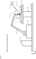
- Figure 1 depicts an illustration of the salient components of additive manufacturing system 100 in accordance with the illustrative embodiment of the present invention.
- Additive manufacturing system 100 comprises: platform 101, robot mount 102, robot arm 103, build plate support 104, build plate 105, supporting structure 106, deposition head 107, tamping tool 108, controller 109, filament reel 110, filament 111, and build volume 112.
- the purpose of manufacturing system 100 is to fabricate an article of manufacture by successively depositing finite lengths of filament on top of each other.
- Platform 101 is a rigid structure that ensures that the relative spatial relationship of robot mount 102, robot arm 103, deposition head 107, and tamping tool 108 are maintained and known with respect to build-plate support 104, build plate 105, and supporting structure 106. It will be clear to those skilled in the art how to make and use platform 101.
- Robot mount 102 is a rigid and stable support for robot arm 103. It will be clear to those skilled in the art how to make and use robot mount 102.
- Robot arm 103 comprises a six-axis mechanical arm that is under the control of controller 109.
- a non-limiting example of robot arm 103 is the IRB 4600 robot offered by ABB.
- Robot arm 103 is capable of depositing a segment of fiber-reinforced thermoplastic filament from any three-dimensional coordinate in build volume 112 to any other three-dimensional coordinate in build volume 112 with deposition head 107 at any approach angle.
- Robot arm 103 can move tamping tool 108 in:
- Build plate support 104 is a rigid and stable support for build plate 105 and supporting structure 106.
- Build plate support 104 comprises a stepper motor - under the control of controller 109 - that is capable of rotating build plate 105 (and, consequently supporting structure 106) around an axis that is normal to the X-Y plane. It will be clear to those skilled in the art how to make and use build plate support 104.
- Build plate 105 is a rigid support onto which supporting structure 106 is rigidly affixed so that it cannot move or rotate independently of build plate 105. It will be clear to those skilled in the art how to make and use build plate 105.
- Supporting structure 106 comprises a plurality of finite lengths of filament that have been deposited and tamped into the shape depicted in Figures 2a, 2b, and 2c .
- Deposition head 107 comprises hardware necessary to (i) deposit a finite length of filament 111 along target path 206 (shown in Figure 2a ) on supporting structure 106, and to (ii) tamp the filament into supporting structure 106 using tamping tool 108, which is a subassembly of deposition head 107.
- Deposition head 107 is described in detail in United States Patent 10,076,870, entitled “Filament Guide,” issued on September, 18, 2018 . Furthermore, ancillary details about deposition head 107 are described in
- Controller 109 comprises the hardware and software necessary to direct build volume 112, robot arm 103, deposition head 107, and build plate support 104, in order to fabricate the article of manufacture. It will be clear to those skilled in the art how to make and use controller 109.
- Filament reel 110 is a circular reel that stores 1000 meters of filament 111 and feeds that filament to deposition head 107. It will be clear to those skilled in the art how to make and use filament reel 110.
- Filament 111 comprises a tow of reinforcing fibers that is substantially parallel to its longitudinal axis.
- filament 111 comprises a cylindrical towpreg of contiguous 12K carbon fiber that is impregnated with thermoplastic resin.
- the cross-section of filament 111 is circular and has a diameter of 200 ⁇ m.
- filament 111 comprises contiguous carbon fiber, but it will be clear to those skilled in the art, after reading this disclosure, how to make and use alternative embodiments of the present invention in which filament 111 has a different fiber composition.
- filament 111 comprises a different number of fibers (e.g., 1K, 3K, 6K, 24K, etc.). It will be clear to those skilled in the art, after reading this disclosure, how to make and use alternative embodiments of the present invention in which the fibers in filament 111 are made of a different material (e.g., fiberglass, aramid, carbon nanotubes, etc.).
- the thermoplastic is, in general, a semi-crystalline polymer and, in particular, the polyaryletherketone (PAEK) known as polyetherketone (PEK).
- PAEK polyaryletherketone
- PEEK polyetheretherketone
- PEKK polyetherketoneketone
- PEEKK polyetherketoneketone
- PEKEKK polyetherketoneetherketoneketone
- the semi-crystalline polymer is not a polyaryletherketone (PAEK) but another semi-crystalline thermoplastic (e.g., polyamide (PA), polybutylene terephthalate (PBT), poly(p-phenylene sulfide) (PPS), etc.) or a mixture of a semi-crystalline polymer and an amorphous polymer.
- PA polyaryletherketone
- PBT polybutylene terephthalate
- PPS poly(p-phenylene sulfide)
- the semi-crystalline polymer can one of the aforementioned materials and the amorphous polymer can be a polyarylsulfone, such as polysulfone (PSU), polyethersulfone (PESU), polyphenylsulfone (PPSU), polyethersulfone (PES), or polyetherimide (PEl).
- PSU polysulfone
- PESU polyethersulfone
- PPSU polyphenylsulfone
- PES polyethersulfone
- PEl polyetherimide
- the amorphous polymer can be, for example and without limitation, polyphenylene oxides (PPOs), acrylonitrile butadiene styrene (ABS), methyl methacrylate acrylonitrile butadiene styrene copolymer (ABSi), polystyrene (PS), or polycarbonate (PC).
- PPOs polyphenylene oxides
- ABS acrylonitrile butadiene styrene
- ABSi methyl methacrylate acrylonitrile butadiene styrene copolymer
- PS polystyrene
- PC polycarbonate
- the disclosed annealing process as it pertains to a blend of an amorphous polymer with a semi-crystalline polymer, takes place generally at a lower temperature than a semi-crystalline polymer with the same glass transition temperature; in some cases, the annealing process can take place at a temperature slightly below the glass transition temperature.
- the weight ratio of semi-crystalline material to amorphous material can be in the range of about 50:50 to about 95:05, inclusive, or about 50:50 to about 90:10, inclusive.
- the weight ratio of semi-crystalline material to amorphous material in the blend is between 60:40 and 80:20, inclusive. The ratio selected for any particular application may vary primarily as a function of the materials used and the properties desired for the printed article.
- the filament comprises a metal.
- the filament can be a wire comprising stainless steel, Inconel (nickel/chrome), titanium, aluminum, cobalt chrome, copper, bronze, iron, precious metals (e.g., platinum, gold, silver, etc.).
- Build volume 112 is the region in three-dimensional space in which robot arm 103 is capable of depositing and tamping filament 111. Supporting structure 106 exists completely within build volume 112.
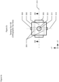
- Figures 2a , 2b , and 2c depict orthographic front, side, and top views of supporting structure 106 in accordance with the illustrative embodiment.
- supporting structure 106 has a rectangular footprint and is 100 mm wide ( i . e ., in the ⁇ x direction) and 50 mm deep ( i . e ., in the ⁇ y direction).
- the bottom surface of supporting structure 106 i . e ., the surface adjacent to build plate 105) is planar, adjacent to build plate 105, and parallel to build plate 105.
- supporting structure 106 has a rectangular footprint, it will be clear to those skilled in the art, after reading this disclosure, how to make and use alternative embodiments of the present invention in which the supporting structure has any footprint.
- supporting structure 106 has a footprint of 100 mm x 50 mm, it will be clear to those skilled in the art, after reading this disclosure, how to make and use alternative embodiments of the present invention of any size.
- supporting structure 106 has a bottom surface that is planar, it will be clear to those skilled in the art, after reading this disclosure, how to make and use alternative embodiments of the present invention in which the bottom surface has any form ( e.g ., planar, non-planar, irregular, convex, concave, hemispherical, etc. ) .
- supporting structure 106 has a bottom surface that is continuous, it will be clear to those skilled in the art, after reading this disclosure, how to make and use alternative embodiments of the present invention in which the bottom surface comprises one or more discontinuities.
- supporting structure 106 has a bottom surface that is adjacent to build plate 105, it will be clear to those skilled in the art, after reading this disclosure, how to make and use alternative embodiments of the present invention in which one or more portions of the bottom surface are not adjacent to the build plate.
- supporting structure 106 has a top surface that is non-planar, it will be clear to those skilled in the art, after reading this disclosure, how to make and use alternative embodiments of the present invention in which the top surface has any form (e.g., planar, irregular, convex, concave, hemispherical, etc. ) .
- supporting structure 106 has a top surface that is continuous, it will be clear to those skilled in the art, after reading this disclosure, how to make and use alternative embodiments of the present invention in which the top surface comprises one or more discontinuities.
- a length of filament is to be deposited and tamped onto the top surface of supporting structure 106.
- the filament is to be deposited onto supporting structure 106 so that the longitudinal axis of the filament is to exactly coincide with a non-planar space curve called target path 206.
- target path 206 is a continuous non-planar curve, but it will be clear to those skilled in the art, after reading this disclosure, how to make and use alternative embodiments of the present invention for any target path (e.g., straight, planar curve, non-planar curve, etc. ) .
- target path 206 does not comprise any discontinuities, but it will be clear to those skilled in the art, after reading this disclosure, how to make and use alternative embodiments of the present invention in which a target path comprises one or more discontinuities.
- FIGS 3a, 3b , and 3c depict orthographic front, side, and top views of tamping tool 108 in accordance with the illustrative embodiment.
- Tamping tool 108 comprises: tool shank 301, wheel bracket 302, wheel axle 303, wheel bushings 304, and wheel 305.
- Wheel 305 is substantially symmetric around wheel axis 312.
- tool shank 301, wheel bracket 302, wheel axle 303, wheel bushings 304, and wheel 305 are each fabricated from stainless steel, but it will be clear to those skilled in the art, after reading this disclosure, how to make and use alternative embodiments of the present invention in which any or all components are fabricated from a different material.
- the angular orientation of wheel 305 changes with respect to the coordinate system of additive manufacturing system 100 as it tamps filament 111.
- the angular orientation of wheel 305 is described in terms of three orthogonal axes:
- the general convention for labeling the roll axis, pitch axis, and yaw axis for aircraft is not adopted for wheel 305 because the analogy is not perfect and might cause confusion when applied to wheel 305.
- the pitch axis of wheel 305 is designated to be the axis - wheel axis 312 - around which wheel 305 exhibits substantial symmetry.
- the roll axis of wheel 305 is designated to be roll axis 314 (shown in Figures 3a and 3b ) because it is, in general, parallel to the direction of travel of wheel 305.
- roll axis 314 intersects wheel axis 312 but unlike an aircraft, is defined to remain horizontal ( i.e ., perpendicular to the Z-axis) and not incline or decline as wheel 305 rotates.
- the yaw axis of wheel 305 is nip axis 311, as shown in Figures 3a, 3b , 3c , and 4 and described in detail below.
- the yaw axis of wheel 305 is pinch axis 313, as shown in Figures 3a, 3b , 3c , and 4 and described in detail below.
- Figure 4 depicts an orthographic front view of tamping tool 108 along cross-section AA-AA in the context of tamping filament 111 onto supporting structure 106 along target path 206.
- wheel 305 exerts different amounts of radial force on filament 111 at different places around its circumference.
- touch line segment 401 is the line segment on the circumferential surface of wheel 305 at which wheel 305 initially touches a length of filament 111. The radial force of wheel 305 on filament 111 at touch line segment 401 approaches zero.
- nip line segment 402 is the line segment on the circumferential surface of wheel 305 where wheel 305 exerts the maximum radial force on a length of filament 111.
- pinch line segment 403 is the line segment on the circumferential surface of wheel 305 where wheel 305 first pinches a length of filament 111 between the circumferential surface and the supporting structure so that any movement of filament 111 parallel to wheel axis 312 is substantially constrained. It will be clear to those skilled in the art, after reading this disclosure, how to determine - both theoretically and empirically - the location of the pinch line segment for every embodiment of the present invention. Pinch line segment 403 is always between touch line segment 401 and nip line segment 402 on the circumferential surface of wheel 305.
- robot arm 103 tamps filament 111 onto supporting structure 106 by steering wheel 305 along target path 206.
- wheel 305 is steered along target path 206:
- nip axis 311 In accordance with the prior art, nip axis 311:
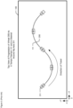
- Figure 5 depicts a top view of the relationship of supporting structure 106, target path 206, and filament 111 after filament 111 has been tamped by wheel 305 and steered using nip axis 311 as the yaw axis, as in the prior art.
- nip axis 311 is used as the yaw axis for wheel 305
- wheel 305 has the detrimental effect of "trapping" the succeeding length of filament 111 off of target path 206 before it is "fixed” in place.
- wheel 305 traps filament wide on curved portions of target path 206. This is clearly disadvantageous.
- wheel 305 is steered along target path 206:
- pinch axis 313 In accordance with the illustrative embodiment, pinch axis 313:
- the value of the offset s depends on the instantaneous curvature of target path 206 at pinch axis 313 with respect to pinch axis 313.
- the offset s has one value when target path 206 has no curvature ( i.e ., is rectilinear) as shown in Figure 4 , a greater value when target path 206 is concave as shown in Figure 7 , and a lesser value when target path 206 is convex, as shown in Figure 8 .
- the value of the offset s is adjusted dynamically as wheel 305 is steered along target path 206. It will be clear to those skilled in the art, after reading this specification, how to determine - both theoretically and empirically - the value(s) for the offset s.
- Figure 6 depicts a top view of the relationship of supporting structure 106, target path 206, and filament 111 after filament 111 has been tamped by wheel 305 and steered using pinch axis 313 as the yaw axis, as in the illustrative embodiment.
- the circumferential surface of wheel 305 precisely tamps filament 111 directly onto target path 206, regardless of the curvature of target path 206 and supporting structure 106.
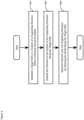
- Figure 9 depicts a flowchart of the operation of the illustrative embodiment.
- an engineer using computer-aided design software establishes a target path on a surface of supporting structure 106 where a segment of filament 111 should be deposited and tamped. It will be clear to those skilled in the art how to accomplish task 901.
- robot arm and tamping tool 108 tamp the length of filament 111 deposited along target path 206 onto in task 902.
- Task 903 is described in detail in Figure 10 and the accompanying text.
- Figure 10 depicts a flowchart of the details of task 903 - tamping filament 111 onto supporting structure 106 with tamping tool 108 by steering wheel 305 along filament 111.
- robot arm 103 and tamping tool 108 - under the control of controller 109 move wheel 305 so that the yaw axis - pinch axis 313 - intersects and advances along target path 206. It will be clear to those skilled in the art, after reading this disclosure, how to make and use embodiments of the present invention that accomplish task 1001.
- robot arm 103 and tamping tool 108 - under the control of controller 109 turn wheel 305 around the yaw axis - pinch axis 313 - to keep the roll axis - roll axis 314 - substantially parallel to target path 206 at the point where the yaw axis intersects target path 206. It will be clear to those skilled in the art, after reading this disclosure, how to make and use embodiments of the present invention that accomplish task 1002.
- robot arm 103 and tamping tool 108 - under the control of controller 109 turn wheel 305 around the roll axis - roll axis 314 - to keep the pitch axis - wheel axis 312 - substantially parallel to supporting structure 106 at the point where the yaw axis - pinch axis 313 - intersects supporting structure 106. It will be clear to those skilled in the art, after reading this disclosure, how to make and use embodiments of the present invention that accomplish task 1003.
Landscapes
- Engineering & Computer Science (AREA)
- Chemical & Material Sciences (AREA)
- Materials Engineering (AREA)
- Manufacturing & Machinery (AREA)
- Mechanical Engineering (AREA)
- Optics & Photonics (AREA)
- Physics & Mathematics (AREA)
- Composite Materials (AREA)
- Robotics (AREA)
- Plasma & Fusion (AREA)
- Health & Medical Sciences (AREA)
- Toxicology (AREA)
- Moulding By Coating Moulds (AREA)
Description
- The present invention relates to additive manufacturing in general, and, more particularly, additive manufacturing processes that use segments of fiber-reinforced thermoplastic filament as their elemental unit of fabrication.
- In the same way that a building can be constructed by successively adding bricks at specific locations and in a specific order, it is well known in the field of additive manufacturing that an article of manufacture can be fabricated by successively adding segments of fiber-reinforced thermoplastic filament at specific locations and in a specific order. A segment of filament is long, thin, and resembles a wet spaghetti when it is heated above a first temperature and a dry spaghetti when it is cooled below a second temperature.
- Adding a segment of filament involves three tasks:
- (1) determining where each segment of filament should be added,
- (2) depositing each segment of filament at the desired location, and
- (3) tamping each segment of filament to ensure adhesion and eliminate voids.
- The task of determining where each segment of filament should be placed is performed by an engineer, a computer-aided design system, or both. Although the task can be performed before the first segment of filament has been added, it can also be performed in real-time during manufacturing to compensate for any discrepancy between where a segment of filament was actually added in contrast to where it should have been added. The location where the longitudinal axis of a segment of filament should be added is called the "target path."
- A target path can comprise:
- (i) one or more straight portions, or
- (ii) one or more planar curved portions, or
- (iii) one or more non-planar curved portions, or
- (iv) any combination of i, ii, and iii.
- Because a segment of filament cannot defy gravity and float in air, the segment of filament must be wholly or partially deposited onto the surface of a supporting structure. Short segments of filament can be cantilevered or suspended, but substantial portions of the segments must be directly undergirded. The supporting structure for a segment of filament can be, but is not limited to:
- (i) a build plate, or
- (ii) a mold, or
- (iii) a mandrel, or
- (iv) a scaffold, or
- (v) one or more previously added segments of filament, or
- (vi) any combination of i, ii, iii, iv, and v.
- Because the target path represents the location where the longitudinal axis of a segment of filament should be added, the target path is near - but not coincident with - the surface of the supporting structure. In most cases, the target path follows the contour of the surface of the adjacent supporting structure.
- The task of depositing a segment of filament at the desired location involves laying down a length of the segment of filament so that the longitudinal axis of the segment exactly coincides with the target path.
- The task of tamping a segment of filament involves pressing the filament into the underlying supporting structure to ensure:
- (i) the cohesion/adhesion of the filament to the supporting structure, and
- (ii) the elimination of air pockets (i.e., voids), which would weaken the final article of manufacture.
- In general, the success of additive manufacturing with segments of filament depends on the ability of the system to add each segment of filament exactly along the target path. Alas, there are circumstances in which this is not readily achievable.
- Some embodiments of the present invention are capable of adding a segment of filament to a supporting structure without some of the costs and disadvantages for doing so in the prior art. In particular, some embodiments of the present invention are able to add a segment of filament to a supporting structure with more spatial precision than in the prior art.
- In some embodiments of the prior art, the task of depositing a segment of filament is finished before tamping the segment is begun. In other words, a segment of filament is deposited along a target path, and, after all of the filament has been deposited, the segment is then tamped. For a variety of reasons, this is disadvantageous.
- In some alternative embodiments of the prior art - and in accordance with the illustrative embodiment - the task of depositing is performed concurrently with the task of tamping. To help understand this, consider four adjacent portions of a segment of filament:
- (1) a first portion of the segment of filament that has been deposited and is being tamped,
- (2) a second portion of the segment of filament, adjacent to the first portion, that is being deposited, and
- (3) a third portion of the segment of filament, adjacent to the second portion, that is about to be deposited, and
- (4) a fourth portion of the segment of filament, adjacent to the third portion, that is to be deposited after the third portion is deposited.
- In this context the inventors of the present invention discovered that when a target path contains a curve (either planar or non-planar), the segment of filament is added outside of the target path instead of along the target path (as shown, for example, in
Figure 5 , where the location offilament 111 does not coincide with target path 206). - To understand the problem, the reader must understand how the second portion is guided into the target path for deposition. In accordance with the prior art and the illustrative embodiment, the second portion is not directly guided into the target path. No machinery or mechanism directly touches the second portion.
- Instead, the second portion is guided, indirectly, by virtue of its position between the first and third portions. In other words, as long as it is free to move, the second portion will exist in a straight line between the first and third portions because of the tension between the first and third portions.
- Whereas the first portion's location while being tamped is fixed, the third portion's location is being moved laterally in order to guide the second portion into the target path. To accomplish this in a curve, the third portion must be moved outside of the curve on a tangent of the curve. Thereafter, while the second portion is tamped on the target path, the fourth portion's location is being moved laterally in order to guide the third portion into the target path.
- In practice, however, the inventors discovered that the wheel is simultaneously:
- (i) tamping the first portion of the segment of filament, and
- (ii) pinching the second portion while it is outside of the target path, which prevents it from being guided into the target path.
- This problem could be ameliorated by using a wheel with a small radius but that does not eliminate problem and there are disadvantages to using a small wheel.
- Another solution involves changing the way that the wheel is steered along the filament. In the prior art and in accordance with the illustrative embodiment, the wheel is steered along the filament so that the wheel's yaw axis intersects and advances along the target path. The prior art and the illustrative embodiment, however, choose different lines for the wheel's yaw axis. These lines are partially defined with respect to the line around which the wheel is substantially symmetric - the wheel's pitch axis.
- In the prior art, a line that intersects the wheel's pitch axis is chosen as the wheel's yaw axis. In contrast, and in accordance with the illustrative embodiment, a line that is offset from the wheel's pitch axis is chosen as the wheel's yaw axis.
- The magnitude of the offset depends on several factors, including:
- (i) the radius of the wheel, and
- (ii) the cross-sectional dimensions of the filament, and
- (iii) the degree to which the filament is compacted when it is tamped, and
- (iv) the curvature of the target path in relation to the curvature of the wheel.
- Furthermore, because the curvature of a target path can change at different locations along the target path, the magnitude of the offset can change at different locations along the target path, and, therefore, the magnitude of the offset - and the location of the wheel's yaw axis relative to its pitch axis - is dynamically adjusted as the wheel advances along the target path.
- The illustrative embodiment comprises: depositing a filament on a surface of a supporting structure along a target path; and tamping the filament onto the supporting structure with a wheel by steering the wheel along the filament; wherein the wheel comprises: (i) a pitch axis around which the wheel is substantially symmetric; and (ii) a circumferential surface that comprises: (ii-a) a nip line segment where the circumferential surface exerts maximum radial force on a first length of the filament, and (ii-b) a pinch line segment where the wheel first pinches a second length of the filament between the circumferential surface and the supporting structure so that any movement of the second length of the filament parallel to the pitch axis is substantially constrained; and (iii) a yaw axis that: (iii-a) is perpendicular to the pitch axis, and (iii-b) has a non-zero offset s from the pitch axis, wherein s is a positive real number, and (iii-c) intersects the pinch line segment; and (iv) a roll axis that intersects the pitch axis and the yaw axis and is perpendicular to the pitch axis and the yaw axis; and wherein steering the wheel comprises moving the wheel so that the yaw axis intersects and advances along the target path.
-
-
Figure 1 depicts an illustration of the salient components ofadditive manufacturing system 100 in accordance with the illustrative embodiment of the present invention. -
Figure 2a depicts an orthogonal top view of supportingstructure 106 in accordance with the illustrative embodiment of the present invention. -
Figure 2b depicts an orthogonal front view of supportingstructure 106 in accordance with the illustrative embodiment of the present invention. -
Figure 2c depicts an orthogonal side view of supportingstructure 106 in accordance with the illustrative embodiment of the present invention. -
Figure 3a depicts an orthogonal side view of tampingtool 108 in accordance with the illustrative embodiment of the present invention. -
Figure 3b depicts an orthogonal front view of tampingtool 108 in accordance with the illustrative embodiment of the present invention. -
Figure 3c depicts an orthogonal top view of tampingtool 108 in accordance with the illustrative embodiment of the present invention. -
Figure 4 depicts an orthographic top view of tampingtool 108 along cross-section AA-AA in the context offilament 111 and a straight target path. -
Figure 5 depicts a top view of the relationship of supportingstructure 106,target path 206, andfilament 111 afterfilament 111 has been tamped bywheel 305 and steered using nipaxis 311 as the yaw axis, as in the prior art. -
Figure 6 depicts a top view of the relationship of supportingstructure 106,target path 206, andfilament 111 afterfilament 111 has been tamped bywheel 305 and steered usingpinch axis 313 as the yaw axis, as in the illustrative embodiment. -
Figure 7 depicts an orthographic front view of tampingtool 108 along cross-section AA-AA in the context offilament 111 and a concave target path. -
Figure 8 depicts an orthographic front view of tampingtool 108 along cross-section AA-AA in the context offilament 111 and a convex target path. -
Figure 9 depicts a flowchart of the operation of the illustrative embodiment. -
Figure 10 depicts a flowchart of the details of task 903 - tampingfilament 111 onto supportingstructure 106 with tampingtool 108 bysteering wheel 305 alongfilament 111. -
Figure 1 depicts an illustration of the salient components ofadditive manufacturing system 100 in accordance with the illustrative embodiment of the present invention.Additive manufacturing system 100 comprises:platform 101,robot mount 102,robot arm 103, buildplate support 104, buildplate 105, supportingstructure 106,deposition head 107, tampingtool 108,controller 109,filament reel 110,filament 111, and buildvolume 112. The purpose ofmanufacturing system 100 is to fabricate an article of manufacture by successively depositing finite lengths of filament on top of each other. -
Platform 101 is a rigid structure that ensures that the relative spatial relationship ofrobot mount 102,robot arm 103,deposition head 107, and tampingtool 108 are maintained and known with respect to build-plate support 104, buildplate 105, and supportingstructure 106. It will be clear to those skilled in the art how to make and useplatform 101. -
Robot mount 102 is a rigid and stable support forrobot arm 103. It will be clear to those skilled in the art how to make and userobot mount 102. -
Robot arm 103 comprises a six-axis mechanical arm that is under the control ofcontroller 109. A non-limiting example ofrobot arm 103 is the IRB 4600 robot offered by ABB.Robot arm 103 is capable of depositing a segment of fiber-reinforced thermoplastic filament from any three-dimensional coordinate inbuild volume 112 to any other three-dimensional coordinate inbuild volume 112 withdeposition head 107 at any approach angle.Robot arm 103 can movetamping tool 108 in: - i. the +X direction,
- ii. the -X direction,
- iii. the +Y direction,
- iv. the -Y direction,
- v. the +Z direction,
- vi. the -Z direction, and
- vii. any combination of i, ii, iii, iv, v, and vi,
-
Build plate support 104 is a rigid and stable support forbuild plate 105 and supportingstructure 106.Build plate support 104 comprises a stepper motor - under the control of controller 109 - that is capable of rotating build plate 105 (and, consequently supporting structure 106) around an axis that is normal to the X-Y plane. It will be clear to those skilled in the art how to make and usebuild plate support 104. -
Build plate 105 is a rigid support onto which supportingstructure 106 is rigidly affixed so that it cannot move or rotate independently ofbuild plate 105. It will be clear to those skilled in the art how to make and usebuild plate 105. - Supporting
structure 106 comprises a plurality of finite lengths of filament that have been deposited and tamped into the shape depicted inFigures 2a, 2b, and 2c . -
Deposition head 107 comprises hardware necessary to (i) deposit a finite length offilament 111 along target path 206 (shown inFigure 2a ) on supportingstructure 106, and to (ii) tamp the filament into supportingstructure 106 usingtamping tool 108, which is a subassembly ofdeposition head 107.Deposition head 107 is described in detail inUnited States Patent 10,076,870, entitled "Filament Guide," issued on September, 18, 2018 deposition head 107 are described in - (i)
United States Patent 10,195,786, entitled "Filament Heating in 3D Printing Systems," issued on February 5, 2019 - (ii)
United States Patent 10,046,511, entitled "Alleviating Torsional Forces on Fiber-Reinforced Thermoplastic Filament," issued on August 14, 2018 - (iii)
United States Patent 11,292,190 entitled "Depositing Arced Portions of Fiber-Reinforced Thermoplastic Filament," issued on April 5, 2022 -
Controller 109 comprises the hardware and software necessary to directbuild volume 112,robot arm 103,deposition head 107, and buildplate support 104, in order to fabricate the article of manufacture. It will be clear to those skilled in the art how to make and usecontroller 109. -
Filament reel 110 is a circular reel that stores 1000 meters offilament 111 and feeds that filament todeposition head 107. It will be clear to those skilled in the art how to make and usefilament reel 110. -
Filament 111 comprises a tow of reinforcing fibers that is substantially parallel to its longitudinal axis. In accordance with the illustrative embodiments,filament 111 comprises a cylindrical towpreg of contiguous 12K carbon fiber that is impregnated with thermoplastic resin. The cross-section offilament 111 is circular and has a diameter of 200 µm. - In accordance with the illustrative embodiment,
filament 111 comprises contiguous carbon fiber, but it will be clear to those skilled in the art, after reading this disclosure, how to make and use alternative embodiments of the present invention in which filament 111 has a different fiber composition. - It will be clear to those skilled in the art, after reading this disclosure, how to make and use alternative embodiments of the present invention in which filament 111 comprises a different number of fibers (e.g., 1K, 3K, 6K, 24K, etc.). It will be clear to those skilled in the art, after reading this disclosure, how to make and use alternative embodiments of the present invention in which the fibers in
filament 111 are made of a different material (e.g., fiberglass, aramid, carbon nanotubes, etc.). - In accordance with the illustrative embodiments, the thermoplastic is, in general, a semi-crystalline polymer and, in particular, the polyaryletherketone (PAEK) known as polyetherketone (PEK). In accordance with some alternative embodiments of the present invention, the semi-crystalline material is the polyaryletherketone (PAEK), polyetheretherketone (PEEK), polyetherketoneketone (PEKK), polyetheretherketoneketone (PEEKK), or polyetherketoneetherketoneketone (PEKEKK). As those who are skilled in the art will appreciate after reading this specification, the disclosed annealing process, as it pertains to a semi-crystalline polymer in general, takes place at a temperature that is above the glass transition temperature Tg.
- In accordance with some alternative embodiments of the present invention, the semi-crystalline polymer is not a polyaryletherketone (PAEK) but another semi-crystalline thermoplastic (e.g., polyamide (PA), polybutylene terephthalate (PBT), poly(p-phenylene sulfide) (PPS), etc.) or a mixture of a semi-crystalline polymer and an amorphous polymer.
- When the filament comprises a blend of an amorphous polymer with a semi-crystalline polymer, the semi-crystalline polymer can one of the aforementioned materials and the amorphous polymer can be a polyarylsulfone, such as polysulfone (PSU), polyethersulfone (PESU), polyphenylsulfone (PPSU), polyethersulfone (PES), or polyetherimide (PEl). In some additional embodiments, the amorphous polymer can be, for example and without limitation, polyphenylene oxides (PPOs), acrylonitrile butadiene styrene (ABS), methyl methacrylate acrylonitrile butadiene styrene copolymer (ABSi), polystyrene (PS), or polycarbonate (PC). As those who are skilled in the art will appreciate after reading this specification, the disclosed annealing process, as it pertains to a blend of an amorphous polymer with a semi-crystalline polymer, takes place generally at a lower temperature than a semi-crystalline polymer with the same glass transition temperature; in some cases, the annealing process can take place at a temperature slightly below the glass transition temperature.
- When the filament comprises a blend of an amorphous polymer with a semi-crystalline polymer, the weight ratio of semi-crystalline material to amorphous material can be in the range of about 50:50 to about 95:05, inclusive, or about 50:50 to about 90:10, inclusive. Preferably, the weight ratio of semi-crystalline material to amorphous material in the blend is between 60:40 and 80:20, inclusive. The ratio selected for any particular application may vary primarily as a function of the materials used and the properties desired for the printed article.
- In some alternative embodiment of the present invention, the filament comprises a metal. For example, and without limitation, the filament can be a wire comprising stainless steel, Inconel (nickel/chrome), titanium, aluminum, cobalt chrome, copper, bronze, iron, precious metals (e.g., platinum, gold, silver, etc.).
-
Build volume 112 is the region in three-dimensional space in whichrobot arm 103 is capable of depositing and tampingfilament 111. Supportingstructure 106 exists completely withinbuild volume 112. -
Figures 2a, 2b, and 2c depict orthographic front, side, and top views of supportingstructure 106 in accordance with the illustrative embodiment. - In accordance with the illustrative embodiment, supporting
structure 106 has a rectangular footprint and is 100 mm wide (i.e., in the Δx direction) and 50 mm deep (i.e., in the Δy direction). The bottom surface of supporting structure 106 (i.e., the surface adjacent to build plate 105) is planar, adjacent to buildplate 105, and parallel to buildplate 105. The top surface of supportingstructure 106 is non-planar, continuous (i.e., comprises no discontinuities), and described by the equation:
range 0 ≤ x ≤ 100. - Although supporting
structure 106 has a rectangular footprint, it will be clear to those skilled in the art, after reading this disclosure, how to make and use alternative embodiments of the present invention in which the supporting structure has any footprint. - Although supporting
structure 106 has a footprint of 100 mm x 50 mm, it will be clear to those skilled in the art, after reading this disclosure, how to make and use alternative embodiments of the present invention of any size. - Although supporting
structure 106 has a bottom surface that is planar, it will be clear to those skilled in the art, after reading this disclosure, how to make and use alternative embodiments of the present invention in which the bottom surface has any form (e.g., planar, non-planar, irregular, convex, concave, hemispherical, etc.). - Although supporting
structure 106 has a bottom surface that is continuous, it will be clear to those skilled in the art, after reading this disclosure, how to make and use alternative embodiments of the present invention in which the bottom surface comprises one or more discontinuities. - Although supporting
structure 106 has a bottom surface that is adjacent to buildplate 105, it will be clear to those skilled in the art, after reading this disclosure, how to make and use alternative embodiments of the present invention in which one or more portions of the bottom surface are not adjacent to the build plate. - Although supporting
structure 106 has a top surface that is non-planar, it will be clear to those skilled in the art, after reading this disclosure, how to make and use alternative embodiments of the present invention in which the top surface has any form (e.g., planar, irregular, convex, concave, hemispherical, etc.). - Although supporting
structure 106 has a top surface that is continuous, it will be clear to those skilled in the art, after reading this disclosure, how to make and use alternative embodiments of the present invention in which the top surface comprises one or more discontinuities. - In accordance with the illustrative embodiment, a length of filament is to be deposited and tamped onto the top surface of supporting
structure 106. In particular, the filament is to be deposited onto supportingstructure 106 so that the longitudinal axis of the filament is to exactly coincide with a non-planar space curve calledtarget path 206. Because the filament has a circular cross-section and a diameter of 200 µm,target path 206 is represented parametrically by the vector function:


range 0 ≥ t >_ 1. - In accordance with the illustrative embodiment,
target path 206 is a continuous non-planar curve, but it will be clear to those skilled in the art, after reading this disclosure, how to make and use alternative embodiments of the present invention for any target path (e.g., straight, planar curve, non-planar curve, etc.). - In accordance with the illustrative embodiment,
target path 206 does not comprise any discontinuities, but it will be clear to those skilled in the art, after reading this disclosure, how to make and use alternative embodiments of the present invention in which a target path comprises one or more discontinuities. -
Figures 3a, 3b , and3c depict orthographic front, side, and top views of tampingtool 108 in accordance with the illustrative embodiment. Tampingtool 108 comprises:tool shank 301,wheel bracket 302,wheel axle 303,wheel bushings 304, andwheel 305.Wheel 305 is substantially symmetric aroundwheel axis 312. - In accordance with the illustrative embodiment,
tool shank 301,wheel bracket 302,wheel axle 303,wheel bushings 304, andwheel 305 are each fabricated from stainless steel, but it will be clear to those skilled in the art, after reading this disclosure, how to make and use alternative embodiments of the present invention in which any or all components are fabricated from a different material. - In accordance with the illustrative embodiment, the angular orientation of
wheel 305 changes with respect to the coordinate system ofadditive manufacturing system 100 as it tampsfilament 111. In accordance with the illustrative embodiment, the angular orientation ofwheel 305 is described in terms of three orthogonal axes: - (i) a pitch axis, and
- (ii) a yaw axis, and
- (iii) a roll axis.
- In accordance with the illustrative embodiment, the general convention for labeling the roll axis, pitch axis, and yaw axis for aircraft is not adopted for
wheel 305 because the analogy is not perfect and might cause confusion when applied towheel 305. - In accordance with the illustrative embodiment, the pitch axis of
wheel 305 is designated to be the axis - wheel axis 312 - around which wheel 305 exhibits substantial symmetry. - In accordance with the illustrative embodiment, the roll axis of
wheel 305 is designated to be roll axis 314 (shown inFigures 3a and 3b ) because it is, in general, parallel to the direction of travel ofwheel 305. In accordance with the illustrative embodiment,roll axis 314 intersectswheel axis 312 but unlike an aircraft, is defined to remain horizontal (i.e., perpendicular to the Z-axis) and not incline or decline aswheel 305 rotates. - In the prior art, the yaw axis of
wheel 305 is nipaxis 311, as shown inFigures 3a, 3b ,3c , and4 and described in detail below. In contrast, and in accordance with the illustrative embodiment, the yaw axis ofwheel 305 ispinch axis 313, as shown inFigures 3a, 3b ,3c , and4 and described in detail below. -
Figure 4 depicts an orthographic front view of tampingtool 108 along cross-section AA-AA in the context of tampingfilament 111 onto supportingstructure 106 alongtarget path 206. - In accordance with the illustrative embodiment,
wheel 305 exerts different amounts of radial force onfilament 111 at different places around its circumference. For example,touch line segment 401 is the line segment on the circumferential surface ofwheel 305 at which wheel 305 initially touches a length offilament 111. The radial force ofwheel 305 onfilament 111 attouch line segment 401 approaches zero. - In contrast, nip
line segment 402 is the line segment on the circumferential surface ofwheel 305 wherewheel 305 exerts the maximum radial force on a length offilament 111. - And in further contrast,
pinch line segment 403 is the line segment on the circumferential surface ofwheel 305 wherewheel 305 first pinches a length offilament 111 between the circumferential surface and the supporting structure so that any movement offilament 111 parallel towheel axis 312 is substantially constrained. It will be clear to those skilled in the art, after reading this disclosure, how to determine - both theoretically and empirically - the location of the pinch line segment for every embodiment of the present invention. Pinchline segment 403 is always betweentouch line segment 401 and nipline segment 402 on the circumferential surface ofwheel 305. - In both the prior art and in accordance with the illustrative embodiment,
robot arm 103 tampsfilament 111 onto supportingstructure 106 bysteering wheel 305 alongtarget path 206. There are significant differences, however, between howwheel 305 is steered in the prior art and in the illustrative embodiment. In the prior art,wheel 305 is steered along target path 206: - (i) by moving
wheel 305 so that the yaw axis - nip axis 311 - intersects and advances alongtarget path 206, and - (ii) by turning
wheel 305 around the yaw axis - nip axis 311 - to keep the roll axis - roll axis 314 - substantially parallel to targetpath 206 at the point where the yaw axis intersectstarget path 206, and - (iii) by turning
wheel 305 around the roll axis - roll axis 314 - to keep the pitch axis - wheel axis 312 - substantially parallel to supportingstructure 106 at the point where the yaw axis - nip axis 311 -intersects supporting structure 106. - In accordance with the prior art, nip axis 311:
- (i) is perpendicular to the pitch axis -
wheel axis 312, and - (ii) intersects the pitch axis -
wheel axis 312, and - (iii) intersects the midpoint of
nip line segment 402. -
Figure 5 depicts a top view of the relationship of supportingstructure 106,target path 206, andfilament 111 afterfilament 111 has been tamped bywheel 305 and steered using nipaxis 311 as the yaw axis, as in the prior art. When nipaxis 311 is used as the yaw axis forwheel 305,wheel 305 has the detrimental effect of "trapping" the succeeding length offilament 111 off oftarget path 206 before it is "fixed" in place. In particular, when nipaxis 311 is used as the yaw axis forwheel axis 312 ,wheel 305 traps filament wide on curved portions oftarget path 206. This is clearly disadvantageous. - In contrast, and in accordance with the illustrative embodiment,
wheel 305 is steered along target path 206: - (i) by moving
wheel 305 so that the yaw axis - pinch axis 313 - intersects and advances alongtarget path 206, and - (ii) by turning
wheel 305 around the yaw axis - pinch axis 313 - to keep the roll axis - roll axis 314 - substantially parallel to targetpath 206 at the point where the yaw axis intersectstarget path 206, and - (iii) by turning
wheel 305 around the roll axis - roll axis 314 - to keep the pitch axis - wheel axis 312 - substantially parallel to supportingstructure 106 at the point where the yaw axis - pinch axis 313 -intersects supporting structure 106. - In accordance with the illustrative embodiment, pinch axis 313:
- (i) is perpendicular to the pitch axis -
wheel axis 312, and - (ii) has a non-zero offset s from the pitch axis - wheel axis 312 (i.e., it does not intersect wheel axis 312), and
- (iii) intersects pinch line segment 403 (e.g., the midpoint of pinch line segment, etc),
- The value of the offset s depends on the instantaneous curvature of
target path 206 atpinch axis 313 with respect to pinchaxis 313. For example, the offset s has one value whentarget path 206 has no curvature (i.e., is rectilinear) as shown inFigure 4 , a greater value whentarget path 206 is concave as shown inFigure 7 , and a lesser value whentarget path 206 is convex, as shown inFigure 8 . In accordance with the illustrative embodiment, the value of the offset s is adjusted dynamically aswheel 305 is steered alongtarget path 206. It will be clear to those skilled in the art, after reading this specification, how to determine - both theoretically and empirically - the value(s) for the offset s. -
Figure 6 depicts a top view of the relationship of supportingstructure 106,target path 206, andfilament 111 afterfilament 111 has been tamped bywheel 305 and steered usingpinch axis 313 as the yaw axis, as in the illustrative embodiment. In accordance with the illustrative embodiment, the circumferential surface ofwheel 305 precisely tampsfilament 111 directly ontotarget path 206, regardless of the curvature oftarget path 206 and supportingstructure 106. -
Figure 9 depicts a flowchart of the operation of the illustrative embodiment. - At
task 901, an engineer using computer-aided design software establishes a target path on a surface of supportingstructure 106 where a segment offilament 111 should be deposited and tamped. It will be clear to those skilled in the art how to accomplishtask 901. - At
task 902,robot arm 103 and deposition head 107 - under the control of controller 109 - deposit a length offilament 111 alongtarget path 206 on supportingstructure 106. It will be clear to those skilled in the art how to accomplishtask 902. - At
task 903, robot arm and tampingtool 108 tamp the length offilament 111 deposited alongtarget path 206 onto intask 902.Task 903 is described in detail inFigure 10 and the accompanying text. - It will be clear to those skilled in the art that
tasks filament 111. -
Figure 10 depicts a flowchart of the details of task 903 - tampingfilament 111 onto supportingstructure 106 with tampingtool 108 bysteering wheel 305 alongfilament 111. - At
task 1001,robot arm 103 and tamping tool 108 - under the control ofcontroller 109move wheel 305 so that the yaw axis - pinch axis 313 - intersects and advances alongtarget path 206. It will be clear to those skilled in the art, after reading this disclosure, how to make and use embodiments of the present invention that accomplishtask 1001. - At
task 1002,robot arm 103 and tamping tool 108 - under the control ofcontroller 109turn wheel 305 around the yaw axis - pinch axis 313 - to keep the roll axis - roll axis 314 - substantially parallel to targetpath 206 at the point where the yaw axis intersectstarget path 206. It will be clear to those skilled in the art, after reading this disclosure, how to make and use embodiments of the present invention that accomplishtask 1002. - At
task 1003,robot arm 103 and tamping tool 108 - under the control ofcontroller 109turn wheel 305 around the roll axis - roll axis 314 - to keep the pitch axis - wheel axis 312 - substantially parallel to supportingstructure 106 at the point where the yaw axis - pinch axis 313 -intersects supporting structure 106. It will be clear to those skilled in the art, after reading this disclosure, how to make and use embodiments of the present invention that accomplishtask 1003.
Claims (9)
- A method comprising:depositing a filament (111) on a surface of a supporting structure (106) along a target path (206); andtamping the filament onto the supporting structure with a wheel by steering the wheel along the filament;wherein the wheel comprises:(i) a pitch axis (312) around which the wheel is substantially symmetric; and(ii) a circumferential surface that comprises:(ii-a) a nip line segment (402) where the wheel exerts maximum radial force on a first length of the filament, and(ii-b) a pinch line segment (403) where the wheel first pinches a second length of the filament between the circumferential surface and the supporting structure so that any movement of the second length of the filament parallel to the pitch axis is substantially constrained; and(iii) a yaw axis (313) that:(iii-a) is perpendicular to the pitch axis, and(iii-b) has a non-zero offset s from the pitch axis, wherein s is a positive real number, and(iii-c) intersects the pinch line segment; and(iv) a roll axis (314) that intersects the pitch axis and the yaw axis and is perpendicular to the pitch axis and the yaw axis; andcharacterized in thatsteering the wheel comprises moving the wheel so that the yaw axis intersects and advances along the target path.
- The method of claim 1 wherein steering the wheel further comprises turning the wheel around the yaw axis to keep the roll axis substantially parallel to the target path at the point where the yaw axis intersects the target path.
- The method of claim 1 or 2 wherein steering the wheel further comprises turning the wheel around the roll axis to keep the pitch axis parallel to the supporting structure at the point where the yaw axis intersects the supporting structure.
- The method of claim 1, 2, or 3 wherein steering the wheel further comprises dynamically adjusting the value of the offset s as a function of the curvature of the target path.
- The method of claim 1, 2, or 3 wherein the filament is an anisotropic fiber-reinforced thermoplastic filament.
- The method of claim 1, 2, or 3 wherein the target path is a planar curve.
- The method of claim 1, 2, or 3 wherein the target path is a non-planar curve.
- The method of claim 1, 2, or 3 wherein the value of the offset s is a function of the cross-sectional dimension of the filament.
- The method of claim 1, 2, or 3 wherein the value of the offset s is a function of the diameter of the wheel.
Applications Claiming Priority (2)
| Application Number | Priority Date | Filing Date | Title |
|---|---|---|---|
| US16/505,541 US11135786B2 (en) | 2019-07-08 | 2019-07-08 | Adding a segment of fiber-reinforced thermoplastic filament in a curve |
| PCT/US2020/038896 WO2021007016A1 (en) | 2019-07-08 | 2020-06-22 | Adding a segment of fiber-reinforced thermoplastic filament in a curve |
Publications (3)
| Publication Number | Publication Date |
|---|---|
| EP3996897A1 EP3996897A1 (en) | 2022-05-18 |
| EP3996897C0 EP3996897C0 (en) | 2024-12-25 |
| EP3996897B1 true EP3996897B1 (en) | 2024-12-25 |
Family
ID=71528073
Family Applications (1)
| Application Number | Title | Priority Date | Filing Date |
|---|---|---|---|
| EP20737806.8A Active EP3996897B1 (en) | 2019-07-08 | 2020-06-22 | Adding a segment of fiber-reinforced thermoplastic filament in a curve |
Country Status (7)
| Country | Link |
|---|---|
| US (1) | US11135786B2 (en) |
| EP (1) | EP3996897B1 (en) |
| JP (1) | JP7597782B2 (en) |
| CN (1) | CN114126845A (en) |
| AU (1) | AU2020311316B2 (en) |
| CA (1) | CA3141361A1 (en) |
| WO (1) | WO2021007016A1 (en) |
Families Citing this family (2)
| Publication number | Priority date | Publication date | Assignee | Title |
|---|---|---|---|---|
| US20230071513A1 (en) * | 2021-09-04 | 2023-03-09 | Continuous Composites Inc. | Print head and method for additive manufacturing system |
| US12600084B2 (en) | 2022-05-12 | 2026-04-14 | Continuous Composites Inc. | Additive manufacturing system |
Family Cites Families (18)
| Publication number | Priority date | Publication date | Assignee | Title |
|---|---|---|---|---|
| US4097324A (en) | 1977-04-04 | 1978-06-27 | Emmel Leroy L | Method and apparatus for making an elongated lattice structure |
| JPS62144927A (en) * | 1985-12-20 | 1987-06-29 | Agency Of Ind Science & Technol | Automatic application process of frp tape and its device |
| US4851065A (en) * | 1986-01-17 | 1989-07-25 | Tyee Aircraft, Inc. | Construction of hollow, continuously wound filament load-bearing structure |
| JPH0725145B2 (en) | 1988-05-24 | 1995-03-22 | 新日本工機株式会社 | Method for controlling tape moving direction in automatic tape sticking device |
| US5213646A (en) * | 1988-12-28 | 1993-05-25 | Andrew M. Zsolnay | Precision method for placing filaments |
| US6026883A (en) * | 1998-04-30 | 2000-02-22 | Alliant Techsystems, Inc. | Self-contained apparatus for fiber element placement |
| US7836931B2 (en) | 2004-06-22 | 2010-11-23 | Slyne William J | Tape laying apparatus and method |
| US7841375B2 (en) | 2006-07-10 | 2010-11-30 | Ingersoll Machine Tools, Inc. | Tow catch for fiber placement head |
| US10169492B2 (en) * | 2011-06-20 | 2019-01-01 | The Boeing Company | Fiber placement optimization for steered-fiber plies |
| US9149988B2 (en) * | 2013-03-22 | 2015-10-06 | Markforged, Inc. | Three dimensional printing |
| US9126367B1 (en) * | 2013-03-22 | 2015-09-08 | Markforged, Inc. | Three dimensional printer for fiber reinforced composite filament fabrication |
| EP3442770A4 (en) * | 2016-04-15 | 2020-02-26 | Cc3D Llc | HEAD AND SYSTEM FOR THE CONTINUOUS PRODUCTION OF A HOLLOW COMPOSITE STRUCTURE |
| US10901386B2 (en) * | 2016-09-06 | 2021-01-26 | Continuous Composites Inc. | Systems and methods for controlling additive manufacturing |
| KR101947050B1 (en) * | 2017-01-23 | 2019-02-12 | 주식회사 신도리코 | Apparatus for driving filament spool of 3D printer |
| US10549477B2 (en) | 2017-02-17 | 2020-02-04 | Thermwood Corporation | Methods and apparatus for controlling an applicator head during additive manufacturing |
| US10195786B1 (en) | 2017-11-30 | 2019-02-05 | Arevo, Inc. | Filament heating in 3D printing systems |
| US10076870B1 (en) * | 2017-11-30 | 2018-09-18 | Arevo, Inc. | Filament guide |
| US10046511B1 (en) | 2017-12-26 | 2018-08-14 | Arevo, Inc. | Alleviating torsional forces on fiber-reinforced thermoplastic filament |
-
2019
- 2019-07-08 US US16/505,541 patent/US11135786B2/en active Active
-
2020
- 2020-06-22 JP JP2022500818A patent/JP7597782B2/en active Active
- 2020-06-22 AU AU2020311316A patent/AU2020311316B2/en active Active
- 2020-06-22 CN CN202080049703.7A patent/CN114126845A/en active Pending
- 2020-06-22 WO PCT/US2020/038896 patent/WO2021007016A1/en not_active Ceased
- 2020-06-22 CA CA3141361A patent/CA3141361A1/en active Pending
- 2020-06-22 EP EP20737806.8A patent/EP3996897B1/en active Active
Also Published As
| Publication number | Publication date |
|---|---|
| EP3996897C0 (en) | 2024-12-25 |
| WO2021007016A1 (en) | 2021-01-14 |
| JP2022540136A (en) | 2022-09-14 |
| JP7597782B2 (en) | 2024-12-10 |
| US11135786B2 (en) | 2021-10-05 |
| AU2020311316B2 (en) | 2026-01-22 |
| AU2020311316A1 (en) | 2022-01-27 |
| US20210008817A1 (en) | 2021-01-14 |
| EP3996897A1 (en) | 2022-05-18 |
| CN114126845A (en) | 2022-03-01 |
| CA3141361A1 (en) | 2021-01-14 |
Similar Documents
| Publication | Publication Date | Title |
|---|---|---|
| US10046511B1 (en) | Alleviating torsional forces on fiber-reinforced thermoplastic filament | |
| US11292190B2 (en) | Depositing arced portions of fiber-reinforced thermoplastic filament | |
| AU2020311316B2 (en) | Adding a segment of fiber-reinforced thermoplastic filament in a curve | |
| Gao et al. | Review of flexible piezoresistive strain sensors in civil structural health monitoring | |
| US10538035B2 (en) | Consumable scaffold for 3D printing of high-tensile-strength materials | |
| Zhang et al. | Multi-axis additive manufacturing process for continuous fibre reinforced composite parts | |
| WO2019108331A1 (en) | Filament heating in 3d printing systems | |
| US20200324403A1 (en) | Methods and apparatus for controlling motion of an articulated robot | |
| Silva et al. | Improving the wear resistance of moulds for the injection of glass fibre–reinforced plastics using PVD coatings: A comparative study | |
| US11084273B2 (en) | Generating tool paths to preserve filament continuity in additive manufacturing | |
| Lu et al. | Nanorobotic system iTRo for controllable 1D micro/nano material twisting test | |
| US10611079B2 (en) | Quadrilateral sparse infill made of linear segments of filament | |
| US11046035B2 (en) | Fiber feathering in additive manufacturing | |
| WO2018169729A1 (en) | Curvilinear duct fabricated with additive manufacturing | |
| Wang et al. | Automated fiber placement path planning and analysis of pressure vessels | |
| Arai | Noncircular tube spinning based on three-dimensional CAD model | |
| Gray et al. | The three‐dimensional geometry of simulated porphyroblast inclusion trails: Inert‐marker, viscous‐flow models | |
| US11325305B2 (en) | Build plate with adhesive islands | |
| CN112639641B (en) | System and method for controlling a packaging machine | |
| CN100441399C (en) | Dough Winding Molding Method of Composite Materials | |
| US20210252783A1 (en) | Thermoplastic Mold with Implicit Registration | |
| JP2004347600A (en) | Apparatus and method for determining the position of a movable object | |
| Mehdikhani et al. | Analysis of void morphology in composite laminates using micro-computed tomography | |
| US20210387407A1 (en) | Method for Heating Fiber-Reinforced Thermoplastic Workpiece | |
| Sorrentino et al. | Robotized filament winding of full section parts: comparison between two winding trajectory planning rules |
Legal Events
| Date | Code | Title | Description |
|---|---|---|---|
| STAA | Information on the status of an ep patent application or granted ep patent |
Free format text: STATUS: UNKNOWN |
|
| STAA | Information on the status of an ep patent application or granted ep patent |
Free format text: STATUS: THE INTERNATIONAL PUBLICATION HAS BEEN MADE |
|
| PUAI | Public reference made under article 153(3) epc to a published international application that has entered the european phase |
Free format text: ORIGINAL CODE: 0009012 |
|
| STAA | Information on the status of an ep patent application or granted ep patent |
Free format text: STATUS: REQUEST FOR EXAMINATION WAS MADE |
|
| 17P | Request for examination filed |
Effective date: 20220125 |
|
| AK | Designated contracting states |
Kind code of ref document: A1 Designated state(s): AL AT BE BG CH CY CZ DE DK EE ES FI FR GB GR HR HU IE IS IT LI LT LU LV MC MK MT NL NO PL PT RO RS SE SI SK SM TR |
|
| DAV | Request for validation of the european patent (deleted) | ||
| DAX | Request for extension of the european patent (deleted) | ||
| GRAP | Despatch of communication of intention to grant a patent |
Free format text: ORIGINAL CODE: EPIDOSNIGR1 |
|
| STAA | Information on the status of an ep patent application or granted ep patent |
Free format text: STATUS: GRANT OF PATENT IS INTENDED |
|
| INTG | Intention to grant announced |
Effective date: 20240716 |
|
| GRAS | Grant fee paid |
Free format text: ORIGINAL CODE: EPIDOSNIGR3 |
|
| GRAA | (expected) grant |
Free format text: ORIGINAL CODE: 0009210 |
|
| STAA | Information on the status of an ep patent application or granted ep patent |
Free format text: STATUS: THE PATENT HAS BEEN GRANTED |
|
| RAP1 | Party data changed (applicant data changed or rights of an application transferred) |
Owner name: STRATASYS, INC. |
|
| AK | Designated contracting states |
Kind code of ref document: B1 Designated state(s): AL AT BE BG CH CY CZ DE DK EE ES FI FR GB GR HR HU IE IS IT LI LT LU LV MC MK MT NL NO PL PT RO RS SE SI SK SM TR |
|
| REG | Reference to a national code |
Ref country code: GB Ref legal event code: FG4D |
|
| REG | Reference to a national code |
Ref country code: CH Ref legal event code: EP |
|
| REG | Reference to a national code |
Ref country code: DE Ref legal event code: R096 Ref document number: 602020043669 Country of ref document: DE |
|
| REG | Reference to a national code |
Ref country code: IE Ref legal event code: FG4D |
|
| U01 | Request for unitary effect filed |
Effective date: 20250124 |
|
| U07 | Unitary effect registered |
Designated state(s): AT BE BG DE DK EE FI FR IT LT LU LV MT NL PT RO SE SI Effective date: 20250130 |
|
| PG25 | Lapsed in a contracting state [announced via postgrant information from national office to epo] |
Ref country code: HR Free format text: LAPSE BECAUSE OF FAILURE TO SUBMIT A TRANSLATION OF THE DESCRIPTION OR TO PAY THE FEE WITHIN THE PRESCRIBED TIME-LIMIT Effective date: 20241225 |
|
| PG25 | Lapsed in a contracting state [announced via postgrant information from national office to epo] |
Ref country code: NO Free format text: LAPSE BECAUSE OF FAILURE TO SUBMIT A TRANSLATION OF THE DESCRIPTION OR TO PAY THE FEE WITHIN THE PRESCRIBED TIME-LIMIT Effective date: 20250325 |
|
| PG25 | Lapsed in a contracting state [announced via postgrant information from national office to epo] |
Ref country code: GR Free format text: LAPSE BECAUSE OF FAILURE TO SUBMIT A TRANSLATION OF THE DESCRIPTION OR TO PAY THE FEE WITHIN THE PRESCRIBED TIME-LIMIT Effective date: 20250326 |
|
| PG25 | Lapsed in a contracting state [announced via postgrant information from national office to epo] |
Ref country code: RS Free format text: LAPSE BECAUSE OF FAILURE TO SUBMIT A TRANSLATION OF THE DESCRIPTION OR TO PAY THE FEE WITHIN THE PRESCRIBED TIME-LIMIT Effective date: 20250325 |
|
| U20 | Renewal fee for the european patent with unitary effect paid |
Year of fee payment: 6 Effective date: 20250520 |
|
| PG25 | Lapsed in a contracting state [announced via postgrant information from national office to epo] |
Ref country code: SM Free format text: LAPSE BECAUSE OF FAILURE TO SUBMIT A TRANSLATION OF THE DESCRIPTION OR TO PAY THE FEE WITHIN THE PRESCRIBED TIME-LIMIT Effective date: 20241225 |
|
| PG25 | Lapsed in a contracting state [announced via postgrant information from national office to epo] |
Ref country code: PL Free format text: LAPSE BECAUSE OF FAILURE TO SUBMIT A TRANSLATION OF THE DESCRIPTION OR TO PAY THE FEE WITHIN THE PRESCRIBED TIME-LIMIT Effective date: 20241225 |
|
| PG25 | Lapsed in a contracting state [announced via postgrant information from national office to epo] |
Ref country code: ES Free format text: LAPSE BECAUSE OF FAILURE TO SUBMIT A TRANSLATION OF THE DESCRIPTION OR TO PAY THE FEE WITHIN THE PRESCRIBED TIME-LIMIT Effective date: 20241225 |
|
| PG25 | Lapsed in a contracting state [announced via postgrant information from national office to epo] |
Ref country code: IS Free format text: LAPSE BECAUSE OF FAILURE TO SUBMIT A TRANSLATION OF THE DESCRIPTION OR TO PAY THE FEE WITHIN THE PRESCRIBED TIME-LIMIT Effective date: 20250425 |
|
| PG25 | Lapsed in a contracting state [announced via postgrant information from national office to epo] |
Ref country code: SK Free format text: LAPSE BECAUSE OF FAILURE TO SUBMIT A TRANSLATION OF THE DESCRIPTION OR TO PAY THE FEE WITHIN THE PRESCRIBED TIME-LIMIT Effective date: 20241225 |
|
| PG25 | Lapsed in a contracting state [announced via postgrant information from national office to epo] |
Ref country code: CZ Free format text: LAPSE BECAUSE OF FAILURE TO SUBMIT A TRANSLATION OF THE DESCRIPTION OR TO PAY THE FEE WITHIN THE PRESCRIBED TIME-LIMIT Effective date: 20241225 |
|
| PLBE | No opposition filed within time limit |
Free format text: ORIGINAL CODE: 0009261 |
|
| STAA | Information on the status of an ep patent application or granted ep patent |
Free format text: STATUS: NO OPPOSITION FILED WITHIN TIME LIMIT |
|
| REG | Reference to a national code |
Ref country code: CH Ref legal event code: L10 Free format text: ST27 STATUS EVENT CODE: U-0-0-L10-L00 (AS PROVIDED BY THE NATIONAL OFFICE) Effective date: 20251105 |
|
| 26N | No opposition filed |
Effective date: 20250926 |
|
| REG | Reference to a national code |
Ref country code: CH Ref legal event code: H13 Free format text: ST27 STATUS EVENT CODE: U-0-0-H10-H13 (AS PROVIDED BY THE NATIONAL OFFICE) Effective date: 20260127 |
|
| PG25 | Lapsed in a contracting state [announced via postgrant information from national office to epo] |
Ref country code: MC Free format text: LAPSE BECAUSE OF FAILURE TO SUBMIT A TRANSLATION OF THE DESCRIPTION OR TO PAY THE FEE WITHIN THE PRESCRIBED TIME-LIMIT Effective date: 20241225 |
|
| GBPC | Gb: european patent ceased through non-payment of renewal fee |
Effective date: 20250622 |
|
| PG25 | Lapsed in a contracting state [announced via postgrant information from national office to epo] |
Ref country code: GB Free format text: LAPSE BECAUSE OF NON-PAYMENT OF DUE FEES Effective date: 20250622 |
|
| PG25 | Lapsed in a contracting state [announced via postgrant information from national office to epo] |
Ref country code: IE Free format text: LAPSE BECAUSE OF NON-PAYMENT OF DUE FEES Effective date: 20250622 |
|
| PG25 | Lapsed in a contracting state [announced via postgrant information from national office to epo] |
Ref country code: CH Free format text: LAPSE BECAUSE OF NON-PAYMENT OF DUE FEES Effective date: 20250630 |