EP3996602B1 - Device for fastening tissue - Google Patents
Device for fastening tissue Download PDFInfo
- Publication number
- EP3996602B1 EP3996602B1 EP20750880.5A EP20750880A EP3996602B1 EP 3996602 B1 EP3996602 B1 EP 3996602B1 EP 20750880 A EP20750880 A EP 20750880A EP 3996602 B1 EP3996602 B1 EP 3996602B1
- Authority
- EP
- European Patent Office
- Prior art keywords
- stapling head
- medical device
- pushing element
- shaft
- distal end
- Prior art date
- Legal status (The legal status is an assumption and is not a legal conclusion. Google has not performed a legal analysis and makes no representation as to the accuracy of the status listed.)
- Active
Links
Images




Classifications
-
- A—HUMAN NECESSITIES
- A61—MEDICAL OR VETERINARY SCIENCE; HYGIENE
- A61B—DIAGNOSIS; SURGERY; IDENTIFICATION
- A61B17/00—Surgical instruments, devices or methods
- A61B17/068—Surgical staplers, e.g. containing multiple staples or clamps
- A61B17/072—Surgical staplers, e.g. containing multiple staples or clamps for applying a row of staples in a single action, e.g. the staples being applied simultaneously
-
- A—HUMAN NECESSITIES
- A61—MEDICAL OR VETERINARY SCIENCE; HYGIENE
- A61B—DIAGNOSIS; SURGERY; IDENTIFICATION
- A61B17/00—Surgical instruments, devices or methods
- A61B17/068—Surgical staplers, e.g. containing multiple staples or clamps
- A61B17/0682—Surgical staplers, e.g. containing multiple staples or clamps for applying U-shaped staples or clamps, e.g. without a forming anvil
- A61B17/0686—Surgical staplers, e.g. containing multiple staples or clamps for applying U-shaped staples or clamps, e.g. without a forming anvil having a forming anvil staying below the tissue during stapling
-
- A—HUMAN NECESSITIES
- A61—MEDICAL OR VETERINARY SCIENCE; HYGIENE
- A61B—DIAGNOSIS; SURGERY; IDENTIFICATION
- A61B17/00—Surgical instruments, devices or methods
- A61B17/068—Surgical staplers, e.g. containing multiple staples or clamps
- A61B17/072—Surgical staplers, e.g. containing multiple staples or clamps for applying a row of staples in a single action, e.g. the staples being applied simultaneously
- A61B17/07207—Surgical staplers, e.g. containing multiple staples or clamps for applying a row of staples in a single action, e.g. the staples being applied simultaneously the staples being applied sequentially
-
- A—HUMAN NECESSITIES
- A61—MEDICAL OR VETERINARY SCIENCE; HYGIENE
- A61B—DIAGNOSIS; SURGERY; IDENTIFICATION
- A61B90/00—Instruments, implements or accessories specially adapted for surgery or diagnosis and not covered by any of the groups A61B1/00 - A61B50/00, e.g. for luxation treatment or for protecting wound edges
- A61B90/36—Image-producing devices or illumination devices not otherwise provided for
- A61B90/361—Image-producing devices, e.g. surgical cameras
-
- A—HUMAN NECESSITIES
- A61—MEDICAL OR VETERINARY SCIENCE; HYGIENE
- A61B—DIAGNOSIS; SURGERY; IDENTIFICATION
- A61B17/00—Surgical instruments, devices or methods
- A61B17/068—Surgical staplers, e.g. containing multiple staples or clamps
-
- A—HUMAN NECESSITIES
- A61—MEDICAL OR VETERINARY SCIENCE; HYGIENE
- A61B—DIAGNOSIS; SURGERY; IDENTIFICATION
- A61B17/00—Surgical instruments, devices or methods
- A61B17/11—Surgical instruments, devices or methods for performing anastomosis; Buttons for anastomosis
- A61B17/115—Staplers for performing anastomosis, e.g. in a single operation
-
- A—HUMAN NECESSITIES
- A61—MEDICAL OR VETERINARY SCIENCE; HYGIENE
- A61B—DIAGNOSIS; SURGERY; IDENTIFICATION
- A61B17/00—Surgical instruments, devices or methods
- A61B2017/00017—Electrical control of surgical instruments
-
- A—HUMAN NECESSITIES
- A61—MEDICAL OR VETERINARY SCIENCE; HYGIENE
- A61B—DIAGNOSIS; SURGERY; IDENTIFICATION
- A61B17/00—Surgical instruments, devices or methods
- A61B17/00234—Surgical instruments, devices or methods for minimally invasive surgery
- A61B2017/00292—Surgical instruments, devices or methods for minimally invasive surgery mounted on or guided by flexible, e.g. catheter-like, means
- A61B2017/003—Steerable
- A61B2017/00318—Steering mechanisms
-
- A—HUMAN NECESSITIES
- A61—MEDICAL OR VETERINARY SCIENCE; HYGIENE
- A61B—DIAGNOSIS; SURGERY; IDENTIFICATION
- A61B17/00—Surgical instruments, devices or methods
- A61B17/00234—Surgical instruments, devices or methods for minimally invasive surgery
- A61B2017/00292—Surgical instruments, devices or methods for minimally invasive surgery mounted on or guided by flexible, e.g. catheter-like, means
- A61B2017/0034—Surgical instruments, devices or methods for minimally invasive surgery mounted on or guided by flexible, e.g. catheter-like, means adapted to be inserted through a working channel of an endoscope
-
- A—HUMAN NECESSITIES
- A61—MEDICAL OR VETERINARY SCIENCE; HYGIENE
- A61B—DIAGNOSIS; SURGERY; IDENTIFICATION
- A61B17/00—Surgical instruments, devices or methods
- A61B2017/00535—Surgical instruments, devices or methods pneumatically or hydraulically operated
- A61B2017/00539—Surgical instruments, devices or methods pneumatically or hydraulically operated hydraulically
-
- A—HUMAN NECESSITIES
- A61—MEDICAL OR VETERINARY SCIENCE; HYGIENE
- A61B—DIAGNOSIS; SURGERY; IDENTIFICATION
- A61B17/00—Surgical instruments, devices or methods
- A61B2017/00535—Surgical instruments, devices or methods pneumatically or hydraulically operated
- A61B2017/00557—Surgical instruments, devices or methods pneumatically or hydraulically operated inflatable
-
- A—HUMAN NECESSITIES
- A61—MEDICAL OR VETERINARY SCIENCE; HYGIENE
- A61B—DIAGNOSIS; SURGERY; IDENTIFICATION
- A61B17/00—Surgical instruments, devices or methods
- A61B2017/00831—Material properties
- A61B2017/00867—Material properties shape memory effect
- A61B2017/00871—Material properties shape memory effect polymeric
-
- A—HUMAN NECESSITIES
- A61—MEDICAL OR VETERINARY SCIENCE; HYGIENE
- A61B—DIAGNOSIS; SURGERY; IDENTIFICATION
- A61B17/00—Surgical instruments, devices or methods
- A61B17/068—Surgical staplers, e.g. containing multiple staples or clamps
- A61B17/072—Surgical staplers, e.g. containing multiple staples or clamps for applying a row of staples in a single action, e.g. the staples being applied simultaneously
- A61B2017/07214—Stapler heads
-
- A—HUMAN NECESSITIES
- A61—MEDICAL OR VETERINARY SCIENCE; HYGIENE
- A61B—DIAGNOSIS; SURGERY; IDENTIFICATION
- A61B17/00—Surgical instruments, devices or methods
- A61B17/068—Surgical staplers, e.g. containing multiple staples or clamps
- A61B17/072—Surgical staplers, e.g. containing multiple staples or clamps for applying a row of staples in a single action, e.g. the staples being applied simultaneously
- A61B2017/07214—Stapler heads
- A61B2017/07228—Arrangement of the staples
-
- A—HUMAN NECESSITIES
- A61—MEDICAL OR VETERINARY SCIENCE; HYGIENE
- A61B—DIAGNOSIS; SURGERY; IDENTIFICATION
- A61B17/00—Surgical instruments, devices or methods
- A61B17/068—Surgical staplers, e.g. containing multiple staples or clamps
- A61B17/072—Surgical staplers, e.g. containing multiple staples or clamps for applying a row of staples in a single action, e.g. the staples being applied simultaneously
- A61B2017/07214—Stapler heads
- A61B2017/07257—Stapler heads characterised by its anvil
-
- A—HUMAN NECESSITIES
- A61—MEDICAL OR VETERINARY SCIENCE; HYGIENE
- A61B—DIAGNOSIS; SURGERY; IDENTIFICATION
- A61B17/00—Surgical instruments, devices or methods
- A61B17/068—Surgical staplers, e.g. containing multiple staples or clamps
- A61B17/072—Surgical staplers, e.g. containing multiple staples or clamps for applying a row of staples in a single action, e.g. the staples being applied simultaneously
- A61B2017/07214—Stapler heads
- A61B2017/07278—Stapler heads characterised by its sled or its staple holder
-
- A—HUMAN NECESSITIES
- A61—MEDICAL OR VETERINARY SCIENCE; HYGIENE
- A61B—DIAGNOSIS; SURGERY; IDENTIFICATION
- A61B17/00—Surgical instruments, devices or methods
- A61B17/28—Surgical forceps
- A61B17/29—Forceps for use in minimally invasive surgery
- A61B2017/2901—Details of shaft
- A61B2017/2905—Details of shaft flexible
-
- A—HUMAN NECESSITIES
- A61—MEDICAL OR VETERINARY SCIENCE; HYGIENE
- A61B—DIAGNOSIS; SURGERY; IDENTIFICATION
- A61B17/00—Surgical instruments, devices or methods
- A61B17/28—Surgical forceps
- A61B17/29—Forceps for use in minimally invasive surgery
- A61B2017/2926—Details of heads or jaws
- A61B2017/2932—Transmission of forces to jaw members
- A61B2017/2933—Transmission of forces to jaw members camming or guiding means
-
- A—HUMAN NECESSITIES
- A61—MEDICAL OR VETERINARY SCIENCE; HYGIENE
- A61B—DIAGNOSIS; SURGERY; IDENTIFICATION
- A61B17/00—Surgical instruments, devices or methods
- A61B17/28—Surgical forceps
- A61B17/29—Forceps for use in minimally invasive surgery
- A61B2017/2926—Details of heads or jaws
- A61B2017/2932—Transmission of forces to jaw members
- A61B2017/2944—Translation of jaw members
-
- A—HUMAN NECESSITIES
- A61—MEDICAL OR VETERINARY SCIENCE; HYGIENE
- A61B—DIAGNOSIS; SURGERY; IDENTIFICATION
- A61B90/00—Instruments, implements or accessories specially adapted for surgery or diagnosis and not covered by any of the groups A61B1/00 - A61B50/00, e.g. for luxation treatment or for protecting wound edges
- A61B90/03—Automatic limiting or abutting means, e.g. for safety
- A61B2090/033—Abutting means, stops, e.g. abutting on tissue or skin
- A61B2090/034—Abutting means, stops, e.g. abutting on tissue or skin abutting on parts of the device itself
-
- A—HUMAN NECESSITIES
- A61—MEDICAL OR VETERINARY SCIENCE; HYGIENE
- A61B—DIAGNOSIS; SURGERY; IDENTIFICATION
- A61B90/00—Instruments, implements or accessories specially adapted for surgery or diagnosis and not covered by any of the groups A61B1/00 - A61B50/00, e.g. for luxation treatment or for protecting wound edges
- A61B90/30—Devices for illuminating a surgical field, the devices having an interrelation with other surgical devices or with a surgical procedure
- A61B2090/306—Devices for illuminating a surgical field, the devices having an interrelation with other surgical devices or with a surgical procedure using optical fibres
-
- A—HUMAN NECESSITIES
- A61—MEDICAL OR VETERINARY SCIENCE; HYGIENE
- A61B—DIAGNOSIS; SURGERY; IDENTIFICATION
- A61B90/00—Instruments, implements or accessories specially adapted for surgery or diagnosis and not covered by any of the groups A61B1/00 - A61B50/00, e.g. for luxation treatment or for protecting wound edges
- A61B90/30—Devices for illuminating a surgical field, the devices having an interrelation with other surgical devices or with a surgical procedure
- A61B2090/309—Devices for illuminating a surgical field, the devices having an interrelation with other surgical devices or with a surgical procedure using white LEDs
-
- A—HUMAN NECESSITIES
- A61—MEDICAL OR VETERINARY SCIENCE; HYGIENE
- A61B—DIAGNOSIS; SURGERY; IDENTIFICATION
- A61B2217/00—General characteristics of surgical instruments
- A61B2217/002—Auxiliary appliance
- A61B2217/005—Auxiliary appliance with suction drainage system
-
- A—HUMAN NECESSITIES
- A61—MEDICAL OR VETERINARY SCIENCE; HYGIENE
- A61B—DIAGNOSIS; SURGERY; IDENTIFICATION
- A61B2217/00—General characteristics of surgical instruments
- A61B2217/002—Auxiliary appliance
- A61B2217/007—Auxiliary appliance with irrigation system
-
- A—HUMAN NECESSITIES
- A61—MEDICAL OR VETERINARY SCIENCE; HYGIENE
- A61B—DIAGNOSIS; SURGERY; IDENTIFICATION
- A61B34/00—Computer-aided surgery; Manipulators or robots specially adapted for use in surgery
- A61B34/30—Surgical robots
-
- A—HUMAN NECESSITIES
- A61—MEDICAL OR VETERINARY SCIENCE; HYGIENE
- A61B—DIAGNOSIS; SURGERY; IDENTIFICATION
- A61B90/00—Instruments, implements or accessories specially adapted for surgery or diagnosis and not covered by any of the groups A61B1/00 - A61B50/00, e.g. for luxation treatment or for protecting wound edges
-
- A—HUMAN NECESSITIES
- A61—MEDICAL OR VETERINARY SCIENCE; HYGIENE
- A61B—DIAGNOSIS; SURGERY; IDENTIFICATION
- A61B90/00—Instruments, implements or accessories specially adapted for surgery or diagnosis and not covered by any of the groups A61B1/00 - A61B50/00, e.g. for luxation treatment or for protecting wound edges
- A61B90/30—Devices for illuminating a surgical field, the devices having an interrelation with other surgical devices or with a surgical procedure
Definitions
- Tissue fastening e.g., stapling
- stapling is used in many laparoscopic procedures. These procedures often involve resecting portions or sections of tissue, followed by closing using staples. An example of a common procedure would be colorectal anastomosis.
- a rigid stapler is often used in hybrid surgeries where physicians use laparoscopic and endoscopic platforms to conduct a procedure. Linear staplers include long rigid members which are incapable of being navigated through tortuous anatomy without causing trauma to the tissue. Physicians also are moving towards endoscopic, outpatient procedures, which would require endoscopic stapling.
- the cutouts are dimensioned to allow movement of the pivot members within the cutouts such that when the tool assembly is in the closed position, the anvil body can be positioned in relation to the staple cartridge in a "parked position" in which the contact surfaces of the anvil body and the staple cartridge are in juxtaposed engagement to a "clamped position” in which the contact surfaces of the anvil body and the staple cartridge are spaced to define a tissue gap.
- US 2015/0048141 A1 discloses a surgical stapler that has a body, a shaft assembly extending distally from the body, and an end effector coupled with a distal end of the shaft assembly.
- the end effector has a stapling head assembly, an anvil, and a vacuum port.
- the vacuum port is operable to draw tissue between the stapling head assembly and the anvil.
- the anvil is operable to move toward and away from the stapling head assembly to thereby capture the tissue drawn between the stapling head assembly and the anvil.
- the stapling head assembly comprises a plurality of wheel assemblies and staple cartridges. At least one wheel assembly is operable to rotate to thereby move the anvil toward and away from the body. The remaining wheel assemblies are operable to rotate to thereby drive staples through the captured tissue.
- the body includes user input features operable to drive the wheel assemblies.
- aspects of the present disclosure relate to, among other things, systems, devices, and methods for fastening tissue, e.g., a flexible endoscope platform with stapling capability.
- a flexible endoscope platform with stapling capability e.g., a flexible endoscope platform with stapling capability.
- Each of the aspects disclosed herein may include one or more of the features described in connection with any of the other disclosed aspects.
- the claimed invention as defined by the appended independent claim 1 concerns a medical device comprising a shaft extending from a proximal end toward a distal end, the shaft extending along a longitudinal axis and including a lumen extending from the proximal end toward the distal end; a first stapling head at the distal end, the first stapling head configured to contain one or more staples, and the first stapling head having a block disposed within, and movable relative to, the first stapling head; a second stapling head at the distal end; and a pushing element extending through the lumen, the pushing element being movable from a first position to a second position, wherein transition of the pushing element from the first position to the second position urges the block to move toward second stapling head along a radially-inward directed path that is substantially perpendicular to the longitudinal axis of the shaft to deploy the one or more staples.
- the second stapling head includes a planar
- the pushing element also includes a third position and a fourth position, before the pushing element is moved from the first position to the second position, wherein movement of the pushing element from the third position to the fourth position causes the first stapling head to move toward the second stapling head.
- the first stapling head also moves toward the second stapling head along the radially-inward directed path that is substantially perpendicular to the longitudinal axis of the shaft, and the planar face of the second stapling head may extend in a plane substantially perpendicular to the radially-inward directed path.
- the medical device may further include a first extension extending proximally from the first stapling head, the first extension having a first ramp at a proximal end; and a distal end of the pushing element may include a second ramp configured to slide against the first ramp when the pushing element is moved from the third position to the fourth position.
- the first ramp may extend radially inwardly in a proximal direction; and the second ramp may extend radially outwardly in a distal direction.
- An outer surface of the pushing element may include a protrusion, wherein the protrusion is configured to directly contact the block.
- the block may include a third ramp, and a distal end of the protrusion may include a fourth ramp configured to slide against the third ramp when the pushing element is moved from the first position to the second position.
- the third ramp may extend radially inwardly in a proximal direction
- the fourth ramp may extend radially outwardly in a distal direction.
- the medical device may further include a first extension extending proximally from the first stapling head, the first extension including a longitudinally extending first recess; and movement of the pushing element from the fourth position to the first position may cause the protrusion to slide through the first recess. While the pushing element moves from the fourth position to the first position, the block may remain stationary relative to the first stapling head.
- the first stapling head may include a second recess coaxial with the first recess; and movement of the pushing element from the first position to the second position may cause a distal end of the protrusion to extend through the second recess and into contact with the block.
- the block may be coupled to an inner surface of the first stapling head by one or more resilient members.
- the medical device may further include a second shaft movable from a first configuration to a second configuration, wherein: when the second shaft is in the first configuration, the first stapling head and the second stapling head are spaced apart from one another by a first distance; and in the second configuration, the second shaft is distal relative to the first configuration, and positions the first stapling head and the second stapling head at a second distance from one another; the second distance being less than the first distance.
- the medical device may further include a first extension extending proximally from the first stapling head, and a second extension extending proximally from the second stapling head, wherein the first extension and the second extension are coupled to one another at a joint, wherein the first and second extensions are movable between: a first configuration where the first stapling head and the second stapling head are spaced apart from one another by a first distance; and a second configuration where the first stapling head and the second stapling head are spaced apart from one another by a second distance, wherein the second distance is less than the first distance.
- a medical device comprising a shaft extending from a proximal end toward a distal end along a longitudinal axis, the shaft including: a first conduit extending from the proximal end toward the distal end; an expandable chamber coupled to the first conduit; and one or more staples coupled to the expandable chamber, wherein, delivery of fluid to the expandable chamber via the first conduit is configured to move the one or more staples toward a surface to deploy the one or more staples by contacting the one or more staples with the surface.
- the shaft may further include a recess at least partially defined by the surface, and expansion of the expandable member moves the one or more staples into the recess.
- the medical device may further include a second conduit extending from the proximal end toward the distal end, wherein the distal end of the shaft is configured to articulate relative to the longitudinal axis when the second conduit is filled with a fluid.
- the medical device may further include an electroactive polymer extending along a portion of the shaft, wherein the distal end of the shaft is configured to articulate relative to the longitudinal axis when current is applied to the electroactive polymer.
- a medical device comprising a shaft extending from a proximal end toward a distal end along a longitudinal axis, the shaft including a lumen extending from the proximal end toward the distal end; a pushing element extending through the lumen, wherein distal movement of the pushing element along the longitudinal axis is configured to deploy one or more staples in a direction substantially perpendicular to the longitudinal axis of the shaft.
- tissue fastening may refer, for example, to stapling, fixing, attaching, fastening, or otherwise joining two portions of tissue together.
- fastener may include staples, clips, elastic bands, suture, or any other fastener known in the art.
- FIGS. 1-6 illustrate an exemplary medical device 100 that may be used to staple tissue 20.
- medical device 100 may be a surgical stapling apparatus configured to engage body tissue 20, apply one or a plurality of surgical fasteners thereto, and optionally form an incision in the fastened body tissue during minimally invasive surgical procedures, such as endoscopic procedures.
- Medical device 100 may be used to apply surgical clips or other fasteners, but will be primarily discussed in the context of applying staples.
- Medical device 100 may include an elongate member or shaft 102 that extends from a proximal end (not shown) toward a distal end 104.
- a stapling assembly 110 may be disposed at distal end 104.
- medical device is shown in FIG. 1 without stapling assembly 110 attached.
- stapling assembly 110 may be movable from a first position, such as a transporting position shown in FIG. 2 , to a second position, such as an operating position shown in FIG. 3 .
- stapling assembly 110 may include one or more struts 112 coupled to distal end 104, or that are movable through lumens 108 of medical device 100.
- Stapling assembly 110 may not be operable in the transporting position shown in FIG. 2 , and may be configured to deliver staples to tissue only when in the operating position shown in FIG. 3 . Stated another way, medical device 100 may not be able to deploy staples or other tissue fastening elements when in a transporting position even in response to an action (e.g., pressing a button on an actuator) from an operator that would deploy the staples or tissue fastening elements when the medical device 100 is in the operating position.
- an action e.g., pressing a button on an actuator
- Shaft 102 may be any suitable endoscopic member configured to bend and articulate so as to traverse tortuous anatomy in a body.
- Shaft 102 may be formed from one or more biocompatible materials, such as, e.g., HDPE, silicone, polyurethane, ETFE, SIBS, PIB-PUR, or any other suitable medical grade polymers, and may be flexible and configured to extend through tortuous anatomy.
- Shaft 102 may extend any length suitable for endoscopic or laparoscopic procedures, and may be configured to be positioned within a working channel of an endoscope. Or, shaft 102 may be positioned in the body without an endoscope.
- Shaft 102 may include illumination/optics assembly 106 and one or more lumens 108.
- endoscopes are referenced herein, reference to endoscopes or endoscopy should not be construed as limiting the possible applications of the disclosed aspects.
- the disclosed aspects may be used with duodenoscopes, bronchoscopes, ureteroscopes, colonoscopes, catheters, diagnostic or therapeutic tools or devices, or other types of medical devices.
- Assembly 106 may include an illumination device and an optics device.
- the illumination device may include one or more of a fiber optic device (e.g., a light cable) or a light-emitting diode (LED) so as to provide illumination light to a location within a body of a subject distal of distal end 104.
- the optics device may include any appropriate device configured to provide a visual image of an internal location of the body of the subject.
- the optics device may include one or more optical elements (e.g., lens, cameras, etc.).
- the one or more lumens 108 may be arranged at any appropriate location about the distal end face of shaft 102.
- the one or more lumens 108 may be arranged to provide irrigation and/or aspiration fluid.
- the one or more lumens 108 may be fluidly coupled to one or more ports (not shown) of a handle (not shown). Such ports may be, in turn, fluidly coupled to one or more sources of irrigation and/or aspiration fluid for delivery via the one or more lumens 108.
- the one or more lumens 108 may be arranged to receive one or more articulation wires (not shown) or the like for imparting selective articulation to at least distal end 104 of shaft 102.
- a tool 114 may extend through lumen 108.
- Tool 114 may be configured to grasp tissue 20, and position tissue 20 within or adjacent to stapling assembly 110.
- tool 114 may include a grasper, forceps, a snare, a clamp, a tissue loop, a helix coil, or a clip applier, or any other tool for performing a medical procedure.
- Flat face 214 may include one or more depressions 212, and acts as an anvil for the legs of staples 244.
- First stapling head 204 may be coupled to shaft 102 by a support 210. It is contemplated that support 210 may extend through one or more lumens of shaft 102 (i.e., a through-the-scope attachment), may be coupled to an exterior of shaft 102 (i.e., an over-the-scope attachment), or may include a combination of such attachments.
- First stapling head 204 also may include a curved radially outward facing surface opposite of flat face 214, and may generally have a half-moon shape, although other suitable shapes also are contemplated.
- second stapling head 206 may include a recess 206a that may be substantially coaxial with recess 222a. Second stapling head 206 also may include an opening 206b, which may be positioned adjacent to flat face 214 of first stapling head 204 during a stapling procedure.
- a block 240 is disposed within second stapling head 206, and is movable within second stapling head 206 and at least partially through opening 206b. Staples may be positioned beneath block 240 (e.g., in a cartridge), and when block 240 is pushed downward, the staples are forced into anvils on the opposing staple head.
- Block 240 also may include a ramped surface 242 at its proximal end that extends radially inward in the proximal direction.
- Ramped surfaces 232 and 242 may cooperate with one another in a substantially similar manner to the manner in which ramped surfaces 224 and 228 cooperate with one another.
- Ramped surfaces 224 and 228 may cooperate with one another such that when pushing element 226 is pushed distally along or parallel to a longitudinal axis of shaft 102, ramped surface 228 urges second stapling head 206 along a radially-inward directed path that is substantially perpendicular to the longitudinal axis of shaft 102 (see FIGS. 8 and 9 ).
- the second predetermined distance may correspond to or may be substantially equal to a length of recess 222a.
- further distal movement of pushing element 226 may deploy block 240 containing one or more staples 244 ( FIGS. 10 and 12 ).
- the further distal travel of pushing element 226 causes protrusion 230 to move through recess 206a and into contact with block 240.
- ramped surface 232 may slide against ramped surface 242 to urge block 240 toward first stapling head 204 (particularly toward flat face 214).
- Springs 213 may extend from the resting states during this movement of block 240.
- Block 240 may travel along a substantially similar trajectory that second stapling head 206 originally travelled (i.e., in a direction perpendicular to the longitudinal axis of shaft 102 and toward first stapling head 204).
- a stop may be included such that, at any time after second stapling head 206 has travelled the predetermined first distance (reached the end of its travel path toward first stapling head 204), a medical professional is required to perform some action to enable pushing element 226 to continue distally to drive block 240.
- the stop may, for example, be incorporated into recess 222a and may block movement of protrusion 230.
- application of additional force to pushing element 226 may cause the stop to deform and move out of the path of pushing element 226.
- movement of the stop may be controlled by an actuator, button, or the like, on a handle of the medical device.
- the inclusion of the stop may enable a medical professional to clamp tissue with only stapling heads 204 and 206, before needing to drive staples 244 through the tissue. This may help a medical professional readjust the clamped tissue sections when, for example, the wrong sections of tissue are grasped.
- stapling heads 312a and 314a are moved toward one another along radially inwardly directed paths ( FIG. 19 ). Once stapling heads 312a and 314a have reached the end of their travel paths such that they are substantially adjacent to one another, a second and separate staple deployment step may be carried out. It is contemplated that medical device 300 may include any other staple deployment mechanism disclosed herein.
- Medical device 400 includes another alternative mechanism for closing two stapling heads, where wires are linked to a scissor joint attached to the stapling heads.
- medical device 400 may include a shaft 402 extending from a proximal end (not shown) toward a distal end.
- Two stapling heads 404 and 406 may extend from the distal end of shaft 402 via supports 408 and 410, respectively.
- Supports 408 and 410 may extend proximally from their respective stapling heads, across one another and connected to one another at a joint 412 (e.g., a scissor joint, pivot, etc.).
- medical device 400 may include any other staple deployment mechanism disclosed herein.
- the fluid delivery mechanism described below with respect to FIGS. 22-24 may be utilized.
- fluid may be delivered to, e.g., stapling head 404, via a conduit 416 to an expandable member (not shown) disposed within stapling head 404.
- the closure of stapling heads 404 and 406 may itself deploy the staples 244.
- the same reservoir may supply both conduits 504, 506, and the flow may be controlled via one or more valves (not shown).
- the fluid circulated through conduits 504 and 506 may be any suitable biocompatible fluid, such as, e.g., sterile water or saline (in case of leaks).
- the controller may include a processor that is generally configured to accept information from the medical device and medical device components, and process the information according to various algorithms to produce control signals for controlling the fluid source 507.
- Articulation of medical device 500 may be achieved, at least in part, by filling first conduit 504 with fluid. Additionally, medical device 500 may be constructed to have a non-uniform stiffness. That is, medical device 500 may exhibit a tendency to bend in one or more directions, as opposed to one or more other directions. Stated another way, medical device 500 may be pre-disposed to articulate away from a longitudinal axis of shaft 501 along a particular trajectory. The tendency or predisposition to bend away from the longitudinal axis may be achieved by forming shaft 501 from at least two materials having different durometers or different hardness.
- first conduit 504 when first conduit 504 is filled with fluid, the portion of shaft 501 having a higher hardness would resist movement, and the portion of shaft 501 having a lower hardness would bend (e.g., as shown in FIGS. 23 and 24 ).
- surface modifications such as, e.g., cuts, slits, recesses, or the like, may be made along only a portion of the outer circumference of shaft 501.
- material may be removed from certain interior portions of shaft 501.
- first conduit 504 fills with fluid in these embodiments, the portions of shaft 501 having surface modifications or otherwise having portions removed may bend, while portions of shaft 501 without such surface modifications or material removed may resist movement.
- Increasing the pressure within first conduit 504 may increase the articulation of shaft 501, while maintaining any particular pressure level may maintain the particular articulation angle.
Landscapes
- Health & Medical Sciences (AREA)
- Life Sciences & Earth Sciences (AREA)
- Surgery (AREA)
- Molecular Biology (AREA)
- Engineering & Computer Science (AREA)
- Biomedical Technology (AREA)
- Heart & Thoracic Surgery (AREA)
- Medical Informatics (AREA)
- Nuclear Medicine, Radiotherapy & Molecular Imaging (AREA)
- Animal Behavior & Ethology (AREA)
- General Health & Medical Sciences (AREA)
- Public Health (AREA)
- Veterinary Medicine (AREA)
- Oral & Maxillofacial Surgery (AREA)
- Pathology (AREA)
- Surgical Instruments (AREA)
Description
- Various aspects of the present disclosure relate generally to tissue fastening, including visualizing, retracting, and coupling tissue. More specifically, embodiments of the present disclosure relate to systems, devices, and related methods for stapling tissue, among other aspects. The claimed invention is concerned with a medical stapling device.
- Tissue fastening (e.g., stapling) is used in many laparoscopic procedures. These procedures often involve resecting portions or sections of tissue, followed by closing using staples. An example of a common procedure would be colorectal anastomosis. In hybrid surgeries where physicians use laparoscopic and endoscopic platforms to conduct a procedure, a rigid stapler is often used. Linear staplers include long rigid members which are incapable of being navigated through tortuous anatomy without causing trauma to the tissue. Physicians also are moving towards endoscopic, outpatient procedures, which would require endoscopic stapling.
-
US 2018/0289371 A1 discloses a surgical stapling device that includes an outer tube, a tool assembly and a drive member. The outer tube has a proximal body portion and a distal channel portion. A distal end of the proximal body portion defines cutouts and the channel portion has an outer surface. The tool assembly has an anvil assembly including an anvil body defining a longitudinal axis and having an outer surface, a tissue contact surface and a pair of pivot members positioned proximally of the tissue contact surface. The pivot members are pivotally received within the cutouts of the proximal body portion of the outer tube. The cartridge assembly includes a staple cartridge and a plurality of staples. The staple cartridge defines a longitudinal axis, a tissue contact surface, and a plurality of staple retention pockets. Each of the staple retention pockets supports one of the plurality of staples. The staple cartridge is supported within the distal channel portion of the outer tube. The anvil body is pivotally supported on the outer tube in relation to the staple cartridge such that the tool assembly is movable between a closed position in which longitudinal axes of the anvil body and the staple cartridge are parallel and an open position in which the longitudinal axes of the anvil body and the staple cartridge define an acute angle. The drive member is supported within the staple cartridge and is translatable through the staple cartridge to eject the plurality of staples from the staple cartridge. The cutouts are dimensioned to allow movement of the pivot members within the cutouts such that when the tool assembly is in the closed position, the anvil body can be positioned in relation to the staple cartridge in a "parked position" in which the contact surfaces of the anvil body and the staple cartridge are in juxtaposed engagement to a "clamped position" in which the contact surfaces of the anvil body and the staple cartridge are spaced to define a tissue gap. -
US 2015/0048141 A1 discloses a surgical stapler that has a body, a shaft assembly extending distally from the body, and an end effector coupled with a distal end of the shaft assembly. The end effector has a stapling head assembly, an anvil, and a vacuum port. The vacuum port is operable to draw tissue between the stapling head assembly and the anvil. The anvil is operable to move toward and away from the stapling head assembly to thereby capture the tissue drawn between the stapling head assembly and the anvil. The stapling head assembly comprises a plurality of wheel assemblies and staple cartridges. At least one wheel assembly is operable to rotate to thereby move the anvil toward and away from the body. The remaining wheel assemblies are operable to rotate to thereby drive staples through the captured tissue. The body includes user input features operable to drive the wheel assemblies. - It is with the above considerations in mind that the improvements of the present disclosure may be useful.
- Aspects of the present disclosure relate to, among other things, systems, devices, and methods for fastening tissue, e.g., a flexible endoscope platform with stapling capability. Each of the aspects disclosed herein may include one or more of the features described in connection with any of the other disclosed aspects.
- The claimed invention as defined by the appended independent claim 1 concerns a medical device comprising a shaft extending from a proximal end toward a distal end, the shaft extending along a longitudinal axis and including a lumen extending from the proximal end toward the distal end; a first stapling head at the distal end, the first stapling head configured to contain one or more staples, and the first stapling head having a block disposed within, and movable relative to, the first stapling head; a second stapling head at the distal end; and a pushing element extending through the lumen, the pushing element being movable from a first position to a second position, wherein transition of the pushing element from the first position to the second position urges the block to move toward second stapling head along a radially-inward directed path that is substantially perpendicular to the longitudinal axis of the shaft to deploy the one or more staples. The second stapling head includes a planar face extending substantially perpendicular to the longitudinal axis, and the planar face is an anvil configured to bend the one or more staples into tissue upon contact with the one or more staples.
- The pushing element also includes a third position and a fourth position, before the pushing element is moved from the first position to the second position, wherein movement of the pushing element from the third position to the fourth position causes the first stapling head to move toward the second stapling head. The first stapling head also moves toward the second stapling head along the radially-inward directed path that is substantially perpendicular to the longitudinal axis of the shaft, and the planar face of the second stapling head may extend in a plane substantially perpendicular to the radially-inward directed path. The medical device may further include a first extension extending proximally from the first stapling head, the first extension having a first ramp at a proximal end; and a distal end of the pushing element may include a second ramp configured to slide against the first ramp when the pushing element is moved from the third position to the fourth position. The first ramp may extend radially inwardly in a proximal direction; and the second ramp may extend radially outwardly in a distal direction. An outer surface of the pushing element may include a protrusion, wherein the protrusion is configured to directly contact the block. The block may include a third ramp, and a distal end of the protrusion may include a fourth ramp configured to slide against the third ramp when the pushing element is moved from the first position to the second position. The third ramp may extend radially inwardly in a proximal direction, and the fourth ramp may extend radially outwardly in a distal direction. The medical device may further include a first extension extending proximally from the first stapling head, the first extension including a longitudinally extending first recess; and movement of the pushing element from the fourth position to the first position may cause the protrusion to slide through the first recess. While the pushing element moves from the fourth position to the first position, the block may remain stationary relative to the first stapling head. The first stapling head may include a second recess coaxial with the first recess; and movement of the pushing element from the first position to the second position may cause a distal end of the protrusion to extend through the second recess and into contact with the block. The block may be coupled to an inner surface of the first stapling head by one or more resilient members. The medical device may further include a second shaft movable from a first configuration to a second configuration, wherein: when the second shaft is in the first configuration, the first stapling head and the second stapling head are spaced apart from one another by a first distance; and in the second configuration, the second shaft is distal relative to the first configuration, and positions the first stapling head and the second stapling head at a second distance from one another; the second distance being less than the first distance. The medical device may further include a first extension extending proximally from the first stapling head, and a second extension extending proximally from the second stapling head, wherein the first extension and the second extension are coupled to one another at a joint, wherein the first and second extensions are movable between: a first configuration where the first stapling head and the second stapling head are spaced apart from one another by a first distance; and a second configuration where the first stapling head and the second stapling head are spaced apart from one another by a second distance, wherein the second distance is less than the first distance.
- Also disclosed herein is a medical device comprising a shaft extending from a proximal end toward a distal end along a longitudinal axis, the shaft including: a first conduit extending from the proximal end toward the distal end; an expandable chamber coupled to the first conduit; and one or more staples coupled to the expandable chamber, wherein, delivery of fluid to the expandable chamber via the first conduit is configured to move the one or more staples toward a surface to deploy the one or more staples by contacting the one or more staples with the surface.
- The shaft may further include a recess at least partially defined by the surface, and expansion of the expandable member moves the one or more staples into the recess. The medical device may further include a second conduit extending from the proximal end toward the distal end, wherein the distal end of the shaft is configured to articulate relative to the longitudinal axis when the second conduit is filled with a fluid. The medical device may further include an electroactive polymer extending along a portion of the shaft, wherein the distal end of the shaft is configured to articulate relative to the longitudinal axis when current is applied to the electroactive polymer.
- Further disclosed yet is a medical device comprising a shaft extending from a proximal end toward a distal end along a longitudinal axis, the shaft including a lumen extending from the proximal end toward the distal end; a pushing element extending through the lumen, wherein distal movement of the pushing element along the longitudinal axis is configured to deploy one or more staples in a direction substantially perpendicular to the longitudinal axis of the shaft.
- It may be understood that both the foregoing general description and the following detailed description are exemplary and explanatory only and are not restrictive of the invention, which is defined by the appended set of claims.
- The accompanying drawings, which are incorporated in and constitute a part of this specification, illustrate exemplary aspects of the present disclosure and together with the description, serve to explain the principles of the disclosure.
-
FIGS. 1-6 are illustrations of an exemplary stapling method. -
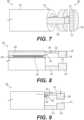
FIG. 7 is a perspective view a medical device according to an embodiment of the claimed invention. -
FIGS. 8-12 are side views illustrating a stapling procedure using the medical device ofFIG. 7 . -
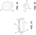
FIG. 13 is a cross-sectional view of a housing and a block of the medical device ofFIGS. 7-12 . -
FIG. 14 is a cross-sectional view of a pushing element of the medical device ofFIGS. 7-12 . -
FIG. 15 is a cross-sectional view of an extension of the medical device ofFIGS. 7-12 . -
FIGS. 16 and17 illustrate movement of the block ofFIG. 13 to deploy one or more staples. -
FIGS. 18 and 19 illustrate another medical device. -
FIGS. 20 and 21 illustrate yet another medical device. -
FIGS. 22-24 are illustrations of yet another medical device. -
FIG. 25 is an illustration of yet another medical device. - The present disclosure is drawn to systems, devices, and methods for coupling, cutting, and resecting tissue, among other aspects. Reference will now be made in detail to aspects of the present disclosure, examples of which are illustrated in the accompanying drawings. Wherever possible, the same or similar reference numbers will be used throughout the drawings to refer to the same or like parts. The term "distal" refers to a portion farthest away from a user when introducing a device into a subject. By contrast, the term "proximal" refers to a portion closest to the user when placing the device into the subject. The term "tissue fastening" may refer, for example, to stapling, fixing, attaching, fastening, or otherwise joining two portions of tissue together. The term "fastener" may include staples, clips, elastic bands, suture, or any other fastener known in the art.
- Both the foregoing general description and the following detailed description are exemplary and explanatory only and are not restrictive of the features of the claimed invention, which is defined by the appended set of claims. As used herein, the terms "comprises," "comprising," "having," "including," or other variations thereof, are intended to cover a non-exclusive inclusion such that a process, method, article, or apparatus that comprises a list of elements does not include only those elements, but may include other elements not expressly listed or inherent to such a process, method, article, or apparatus. Additionally, the term "exemplary" is used herein in the sense of "example," rather than "ideal." As used herein, the terms "about," "substantially," and "approximately," indicate a range of values within +/- 5% of the stated value unless otherwise stated.
-
FIGS. 1-6 illustrate an exemplarymedical device 100 that may be used tostaple tissue 20. In some embodiments,medical device 100 may be a surgical stapling apparatus configured to engagebody tissue 20, apply one or a plurality of surgical fasteners thereto, and optionally form an incision in the fastened body tissue during minimally invasive surgical procedures, such as endoscopic procedures.Medical device 100 may be used to apply surgical clips or other fasteners, but will be primarily discussed in the context of applying staples. -
Medical device 100 may include an elongate member orshaft 102 that extends from a proximal end (not shown) toward adistal end 104. A staplingassembly 110 may be disposed atdistal end 104. For clarity, medical device is shown inFIG. 1 without staplingassembly 110 attached. In some embodiments, staplingassembly 110 may be movable from a first position, such as a transporting position shown inFIG. 2 , to a second position, such as an operating position shown inFIG. 3 . In some examples, staplingassembly 110 may include one ormore struts 112 coupled todistal end 104, or that are movable throughlumens 108 ofmedical device 100.Stapling assembly 110 may not be operable in the transporting position shown inFIG. 2 , and may be configured to deliver staples to tissue only when in the operating position shown inFIG. 3 . Stated another way,medical device 100 may not be able to deploy staples or other tissue fastening elements when in a transporting position even in response to an action (e.g., pressing a button on an actuator) from an operator that would deploy the staples or tissue fastening elements when themedical device 100 is in the operating position. -
Shaft 102 may be any suitable endoscopic member configured to bend and articulate so as to traverse tortuous anatomy in a body.Shaft 102 may be formed from one or more biocompatible materials, such as, e.g., HDPE, silicone, polyurethane, ETFE, SIBS, PIB-PUR, or any other suitable medical grade polymers, and may be flexible and configured to extend through tortuous anatomy.Shaft 102 may extend any length suitable for endoscopic or laparoscopic procedures, and may be configured to be positioned within a working channel of an endoscope. Or,shaft 102 may be positioned in the body without an endoscope.Shaft 102 may include illumination/optics assembly 106 and one ormore lumens 108. Although endoscopes are referenced herein, reference to endoscopes or endoscopy should not be construed as limiting the possible applications of the disclosed aspects. For example, the disclosed aspects may be used with duodenoscopes, bronchoscopes, ureteroscopes, colonoscopes, catheters, diagnostic or therapeutic tools or devices, or other types of medical devices. -
Assembly 106 may include an illumination device and an optics device. For example, the illumination device may include one or more of a fiber optic device (e.g., a light cable) or a light-emitting diode (LED) so as to provide illumination light to a location within a body of a subject distal ofdistal end 104. The optics device may include any appropriate device configured to provide a visual image of an internal location of the body of the subject. For example, the optics device may include one or more optical elements (e.g., lens, cameras, etc.). - The one or
more lumens 108 may be arranged at any appropriate location about the distal end face ofshaft 102. In some arrangements, the one ormore lumens 108 may be arranged to provide irrigation and/or aspiration fluid. In such cases, the one ormore lumens 108 may be fluidly coupled to one or more ports (not shown) of a handle (not shown). Such ports may be, in turn, fluidly coupled to one or more sources of irrigation and/or aspiration fluid for delivery via the one ormore lumens 108. Further, the one ormore lumens 108 may be arranged to receive one or more articulation wires (not shown) or the like for imparting selective articulation to at leastdistal end 104 ofshaft 102. In one embodiment, atool 114 may extend throughlumen 108.Tool 114 may be configured to grasptissue 20, andposition tissue 20 within or adjacent to staplingassembly 110. For example,tool 114 may include a grasper, forceps, a snare, a clamp, a tissue loop, a helix coil, or a clip applier, or any other tool for performing a medical procedure. - In
FIG. 4 ,tool 114 is shown being extended towardtissue 20. InFIG. 5 ,tool 114 is shown positioningtissue 20 between adjacent stapling heads of staplingassembly 110. InFIG. 6 , afirst tissue portion 22 is shown with a first row ofstaples 244 deployed therein, while asecond tissue portion 24 is shown with a second row ofstaples 244 deployed therethrough. The separate stapling heads of staplingassembly 110 may be moved together by actuation of a push button or other mechanism, which ejects a staple from one stapling head toward the other stapling head.Medical device 100 also may include one or more tools for separating stapled tissue portions, such as, e.g., a knife. - A
medical device 200 according to the claimed invention is shown inFIGS. 7-12 .Medical device 200 includes ashaft 102 as set forth inFIGS. 1-6 .Medical device 200 also includes one or more staples 244 (FIGS. 11 and 12 ) configured to be deployed along a trajectory that is substantially perpendicular to the longitudinal axis ofshaft 102.Medical device 200 may include a navigation state (FIG. 2 ), wherestaples 244 may be positioned proximally to articulating portions ofshaft 102. In the navigation state, the stapling heads of staplingassembly 110 are positioned close to the distal face ofelongate member 102. The stapler is intended to be close to the face ofelongate member 102, to make traversing through anatomy easier when not using the stapling function. The stapling heads of stapling assembly may rest in an open position (both in the navigation state and in the operating position) to maintain visualization. The stapling head may be pushed forward using a mechanical driving mechanism (e.g., driving wires, sheath, etc.) which may be connected to the struts. The driving mechanism may extend through the scope to the proximal end to be actuated in the handle by a medical profession. Oncemedical device 200 is moved to a desired location, a tissue acquisition feature, e.g.,tool 114 described with reference toFIGS. 1-6 , located internal or external toshaft 102 can be used to acquire and position tissue for stapling. - The
medical device 200 includes a staplingassembly 202 disposed atdistal end 104.Stapling assembly 202 includes afirst stapling head 204 that may be fixed todistal end 104, and asecond stapling head 206 that may be movable relative todistal end 104. In other embodiments,first stapling head 204 andsecond stapling head 206 may be movable between a transporting configuration, and an operable configuration, in a similar manner as described above with reference toFIGS. 1-6 . First staplinghead 204 includes aflat face 214 that extends substantially perpendicular to a longitudinal axis ofshaft 102.Flat face 214 may include one ormore depressions 212, and acts as an anvil for the legs ofstaples 244. First staplinghead 204 may be coupled toshaft 102 by asupport 210. It is contemplated thatsupport 210 may extend through one or more lumens of shaft 102 (i.e., a through-the-scope attachment), may be coupled to an exterior of shaft 102 (i.e., an over-the-scope attachment), or may include a combination of such attachments. First staplinghead 204 also may include a curved radially outward facing surface opposite offlat face 214, and may generally have a half-moon shape, although other suitable shapes also are contemplated. -
Second stapling head 206 may be disposed within ahousing 220 that is coupled todistal end 104. In some embodiments,housing 220 may be fixed todistal end 104 by a through-the-scope attachment, an over-the-scope attachment, or by a combination of attachment types. Anextension 222 may extend proximally fromsecond stapling head 206. The proximal end ofextension 222 may include a rampedsurface 224, which extends radially inward in the proximal direction.Extension 222 also may include arecess 222a formed in its outer surface (FIG. 15 ). A pushingelement 226 extends throughlumen 108 ofshaft 102. The distal end of pushingelement 226 may include a rampedsurface 228 that extends radially outward in the distal direction. Rampedsurface 228 may be configured in any manner to engage with corresponding rampedsurface 224 of theextension 222. Pushingelement 226 also may include aprotrusion 230 extending from its outer surface. The distal end ofprotrusion 230 may include a rampedsurface 232 that extends radially outward in the distal direction (like ramped surface 228). Rampedsurface 232 may be continuous with ramped surface 228 (i.e., may be coaxial or collinear), and may be proximal to an entirety of ramped surface 228).Recess 222a may be configured to receiveprotrusion 230, and may have a radial dimension b that is slightly longer or substantially equal to a dimension c that protrusion 230 extends from the outer surface of pushing element 226 (referring toFIGS. 14 and 15 ). - Referring to
FIG. 13 ,second stapling head 206 may include arecess 206a that may be substantially coaxial withrecess 222a.Second stapling head 206 also may include anopening 206b, which may be positioned adjacent toflat face 214 offirst stapling head 204 during a stapling procedure. Ablock 240 is disposed withinsecond stapling head 206, and is movable withinsecond stapling head 206 and at least partially throughopening 206b. Staples may be positioned beneath block 240 (e.g., in a cartridge), and when block 240 is pushed downward, the staples are forced into anvils on the opposing staple head.Recess 206a may have a length/width dimension a that is less than dimension c ofprotrusion 230, so thatprotrusion 230 may extend throughrecess 206a to contactblock 240.Block 240 may be biased toward a first configuration shown inFIG. 13 , for example, by one or more resilient members or springs 213 attached to block 240 and to an inner surface ofsecond stapling head 206. Twosprings 213 are shown inFIG. 13 that are compressed in a resting state, although more or fewer springs also are contemplated. Thesprings 213 may be extended whenprotrusion 230 of pushingelement 226 contacts and urges block 240 towardflat face 214 to deploystaples 244. Block 240 also may include a rampedsurface 242 at its proximal end that extends radially inward in the proximal direction. Rampedsurfaces surfaces - The various steps of operating
medical device 200 will now be described. Rampedsurfaces element 226 is pushed distally along or parallel to a longitudinal axis ofshaft 102, rampedsurface 228 urgessecond stapling head 206 along a radially-inward directed path that is substantially perpendicular to the longitudinal axis of shaft 102 (seeFIGS. 8 and 9 ). Aftersecond stapling head 206 reaches the end of its travel path and has travelled a predetermined first distance (towardfirst stapling head 204 in a direction perpendicular to the longitudinal axis of shaft 102), further distal movement of pushingelement 226 may causeprotrusion 230 to extend throughrecess 222a of extension 222 (e.g.,FIG. 11 ). For at least a second predetermined distance, additional distal movement of pushingelement 226 may causeprotrusion 230 to slide, translate, or move relative to and/or throughrecess 222a without causing any movement ofblock 240 relative to second stapling head 206 (FIG. 11 ). In some embodiments, the second predetermined distance may correspond to or may be substantially equal to a length ofrecess 222a. However, after pushingelement 226 has travelled the second predetermined distance, further distal movement of pushingelement 226 may deploy block 240 containing one or more staples 244 (FIGS. 10 and 12 ). In particular, the further distal travel of pushingelement 226 causes protrusion 230 to move throughrecess 206a and into contact withblock 240. In particular, rampedsurface 232 may slide against rampedsurface 242 to urge block 240 toward first stapling head 204 (particularly toward flat face 214).Springs 213 may extend from the resting states during this movement ofblock 240.Block 240 may travel along a substantially similar trajectory that second staplinghead 206 originally travelled (i.e., in a direction perpendicular to the longitudinal axis ofshaft 102 and toward first stapling head 204). - Urging
block 240 towardflat face 214 causes the legs ofstaples 244 to contact flat face 214 (seeFIGS. 16 and 17 ), deployingstaples 244 into tissue disposed betweenfirst stapling head 204 and second stapling head 206 (FIGS. 10 and 12 ). After the staple deployment is complete, a distally-directed force acting on pushingelement 226 may be released (or reversed), causingsprings 213 to move back to their resting, compressed configurations, and retractingblock 240 intohousing 206. Furthermore, the release (or reversal) of the distally directed force on pushingelement 226 may cause the entirety ofsecond stapling head 206 to move radially outward, along the path perpendicular to the longitudinal axis ofshaft 102, to its original position. - It is contemplated that movement of pushing
element 226 from the position shown inFIG. 8 , to the position shown inFIGS. 10 and 12 (after deployment of staple 244), may be performed with a single, smooth motion. However, in some embodiments, a stop may be included such that, at any time aftersecond stapling head 206 has travelled the predetermined first distance (reached the end of its travel path toward first stapling head 204), a medical professional is required to perform some action to enable pushingelement 226 to continue distally to driveblock 240. The stop may, for example, be incorporated intorecess 222a and may block movement ofprotrusion 230. In some embodiments, application of additional force to pushingelement 226 may cause the stop to deform and move out of the path of pushingelement 226. In other embodiments, movement of the stop may be controlled by an actuator, button, or the like, on a handle of the medical device. The inclusion of the stop may enable a medical professional to clamp tissue with only staplingheads staples 244 through the tissue. This may help a medical professional readjust the clamped tissue sections when, for example, the wrong sections of tissue are grasped. - Another
medical device 300 is shown inFIGS. 18 and19.Medical device 300 includes an alternative mechanism for moving two stapling heads closer to one another, where an outer shaft slides over the stapling heads to force them toward one another. For example,medical device 300 may include ashaft 302 extending from a proximal end (not shown) toward adistal end 304. Ashaft 310 may extend within a lumen ofshaft 302. Two staplingheads shaft 310 viasupports Supports shaft 310. Asshaft 302 is moved distally relative to shaft 310 (orshaft 310 and supports 312 and 314 are moved proximally relative to shaft 302), stapling heads 312a and 314a are moved toward one another along radially inwardly directed paths (FIG. 19 ). Once staplingheads medical device 300 may include any other staple deployment mechanism disclosed herein. For example, apusher element 226 may extend throughsupport 312 and cause a block 240 (within, e.g.,first stapling head 312a) to drivestaples 244 into a surface of staplinghead 314a. Alternatively, the fluid delivery mechanism described below with respect toFIGS. 22-24 may be utilized. In yet another embodiment, the closure of staplingheads staples 244. - Yet another
medical device 400 is shown inFIGS. 20 and 21 .Medical device 400 includes another alternative mechanism for closing two stapling heads, where wires are linked to a scissor joint attached to the stapling heads. For example,medical device 400 may include ashaft 402 extending from a proximal end (not shown) toward a distal end. Two staplingheads shaft 402 viasupports Supports members 414 may extend proximally from eachsupport wires 414 may cause stapling heads 404 and 406 to move toward one another (FIG. 21 ). More specifically, proximal and radially inward directed forces may be applied to eachwire 414. Because the working channel is small, pulling back on the wires may be sufficient to create the radially inward directed force necessary (so long as there is enough room for the wires to travel inward as they are pulled). The wires may be connected to a button or other actuation mechanism in the handle, so the user does not pull the wires directly. Once stapling heads 404 and 406 have reached the end of their travel paths and are adjacent to one another, a second and separate staple deployment step may be carried out. It is contemplated thatmedical device 400 may include any other staple deployment mechanism disclosed herein. For example, the fluid delivery mechanism described below with respect toFIGS. 22-24 may be utilized. For example, fluid may be delivered to, e.g., staplinghead 404, via aconduit 416 to an expandable member (not shown) disposed within staplinghead 404. In yet another embodiment, the closure of stapling heads 404 and 406 may itself deploy thestaples 244. -
FIGS. 22-24 show anothermedical device 500, still, that may be used tostaple tissue 20.Medical device 500 may include an elongate member orshaft 501 that extends from a proximal end (not shown) toward adistal end 502.Medical device 500 may include a distally-facing surface orend face 503 atdistal end 502.Medical device 500 also may include a firstfluid conduit 504 and a secondfluid conduit 506. Secondfluid conduit 506 may terminate at its distal end at anexpandable chamber 508. -
Expandable chamber 508 may be movable from a first configuration (shown inFIGS. 22 and 23 ) to a second configuration (shown inFIG. 24 ).Expandable chamber 508 may have a first volume in the first configuration, which is smaller than a second volume in a second configuration. The second volume may be 1.5, 2, 3, or more times larger than the first volume, although other suitable ratios also are contemplated. The exterior of expandable chamber may be formed by an expandable and resilient material, such as, e.g., rubber, polymers, or the like. -
Medical device 500 also may include arecess 509 formed within distally-facingsurface 503. However, it also is contemplated thatrecess 509 may be alternatively, or additionally, formed in a circumferential side surface ofshaft 501. Recess 509 may be partially-defined by a flat surface 510 (which may act as an anvil during a stapling procedure).Expandable chamber 508 may be coupled to one ormore staples 244, and may be arranged withindistal end 502 such that the expansion ofexpandable chamber 508 is in the direction ofrecess 509. For example, solid and relatively stiff material may surround most portions ofexpandable chamber 508, while anopening 511 is disposed betweenexpandable chamber 508 andrecess 509. In this configuration, the expansion ofexpandable chamber 508 must be throughopening 511 and intorecess 509. Alternatively,expandable chamber 508 may not expand intorecess 509 itself, but rather may drivestaples 244 into and/or throughrecess 509 towardflat face 510. The driving ofstaples 244 intoflat face 510 may occur along a trajectory that is substantially perpendicular to the plane offlat face 510. - First and
second conduits fluid source 507, configured to drive fluid through the conduits.Fluid source 507 may be a pump controlled by a controller. The pump may be any suitable pump, such as, e.g., a peristaltic pump, piston pump, motorized pump, microfluidic pump, infusion pump, or the like. The pump may be powered by electrical power, mechanical power, chemical power, or another suitable mechanism.Fluid source 507 may include a source (e.g., a reservoir) of fluid to be circulated throughconduits fluid source 507 may include a plurality of reservoirs, and may deliver fluid through eachconduit conduits conduits fluid source 507. For example, the processor may accept information from the system and system components, process the information according to various algorithms, and produce information signals that may be directed to visual indicators, digital displays, audio tone generators, or other indicators of, e.g., a user interface, in order to inform a user of the system status, component status, procedure status or any other information that is being monitored by the system. The processor may be a digital IC processor, analog processor or any other suitable logic or control system that carries out the control algorithms. One or more pressure sensors may be coupled to eachfluid conduit conduits - Articulation of
medical device 500 may be achieved, at least in part, by fillingfirst conduit 504 with fluid. Additionally,medical device 500 may be constructed to have a non-uniform stiffness. That is,medical device 500 may exhibit a tendency to bend in one or more directions, as opposed to one or more other directions. Stated another way,medical device 500 may be pre-disposed to articulate away from a longitudinal axis ofshaft 501 along a particular trajectory. The tendency or predisposition to bend away from the longitudinal axis may be achieved by formingshaft 501 from at least two materials having different durometers or different hardness. In this embodiment, whenfirst conduit 504 is filled with fluid, the portion ofshaft 501 having a higher hardness would resist movement, and the portion ofshaft 501 having a lower hardness would bend (e.g., as shown inFIGS. 23 and 24 ). In another embodiment, surface modifications such as, e.g., cuts, slits, recesses, or the like, may be made along only a portion of the outer circumference ofshaft 501. Similarly, material may be removed from certain interior portions ofshaft 501. Whenfirst conduit 504 fills with fluid in these embodiments, the portions ofshaft 501 having surface modifications or otherwise having portions removed may bend, while portions ofshaft 501 without such surface modifications or material removed may resist movement. Increasing the pressure withinfirst conduit 504 may increase the articulation ofshaft 501, while maintaining any particular pressure level may maintain the particular articulation angle. - In yet another example shown in
FIG. 25 , articulation of ashaft 601 may be achieved via the use ofelectroactive polymers 604, in place of the pressurized fluid. For example,such polymers 604 may contain cationic materials, which are randomly dispersed and without orientation. The surface on one side ofshaft 601 adjacent to thepolymer 604 may includeanionic material 605. When an electrical current is activated in agenerator 607 coupled topolymer 604, the cations inpolymer 604 may orient and migrate towards theanionic material 605. This in turn may causepolymer 604 to bend. If the electrical current is flowing throughpolymer 604,shaft 601 maintains its bent configuration. In other words, the articulation ofshaft 601 may be maintained during any 'on' cycle of an electrical generator coupled to the polymer. It also is contemplated thatpolymer 604 may include anionic materials, which are randomly dispersed and without orientation, and thatmaterial 605 includes cationic material. In still further examples, a magnetic attraction betweenpolymer 604 andmaterial 605 may be utilized to achieve the articulation. - It will be apparent to those skilled in the art that various modifications and variations may be made in the disclosed devices and methods without departing from the scope of the disclosure. Other aspects of the disclosure will be apparent to those skilled in the art from consideration of the specification and practice of the features disclosed herein. It is intended that the specification and examples be considered as exemplary only. The scope of the claimed invention is defined by the appended set of claims.
Claims (11)
- A medical device (100, 200), comprising:a shaft (102) extending from a proximal end toward a distal end (104), the shaft extending along a longitudinal axis and the shaft including a lumen (108) extending from the proximal end toward the distal end;a first stapling head (206) at the distal end, the first stapling head configured to contain one or more staples (244), and the first stapling head having a block (240) disposed within, and movable relative to, the first stapling head;a second stapling head (204) at the distal end; anda pushing element (226) extending through the lumen, the pushing element being movable from a first position to a second position, wherein transition of the pushing element from the first position to the second position urges the block to move toward the second stapling head along a radially-inward directed path that is substantially perpendicular to the longitudinal axis of the shaft to deploy the one or more staples;wherein the second stapling head includes a planar face (214) extending substantially perpendicular to the longitudinal axis, wherein the planar face is an anvil configured to bend the one or more staples into tissue (20) upon contact with the one or more staples,wherein the pushing element also includes a third position and a fourth position, before the pushing element is moved from the first position to the second position, and wherein movement of the pushing element from the third position to the fourth position causes the first stapling head to move toward the second stapling head, andwherein the first stapling head also moves toward the second stapling head along the radially-inward directed path that is substantially perpendicular to the longitudinal axis of the shaft.
- The medical device of claim 1, wherein the planar face of the second stapling head extends in a plane substantially perpendicular to the radially-inward directed path.
- The medical device of any one of claims 1 to 2, wherein:the medical device includes a first extension (222) extending proximally from the first stapling head, the first extension having a first ramp (224) at a proximal end; anda distal end of the pushing element includes a second ramp (228) configured to slide against the first ramp when the pushing element is moved from the third position to the
- The medical device of claim 3, wherein:the first ramp extends radially inwardly in a proximal direction; andthe second ramp extends radially outwardly in a distal direction.
- The medical device of any one of claims 1 to 4, wherein an outer surface of the pushing element includes a protrusion (230), wherein the protrusion is configured to directly contact the block.
- The medical device of claim 5, wherein the block includes a third ramp (242), and a distal end of the protrusion includes a fourth ramp (232) configured to slide against the third ramp when the pushing element is moved from the first position to the second position.
- The medical device of claim 6, wherein the third ramp extends radially inwardly in a proximal direction, and the fourth ramp extends radially outwardly in a distal direction.
- The medical device of claim 5, wherein:the medical device further includes a first extension (222) extending proximally from the first stapling head, the first extension including a longitudinally extending first recess (222a); andmovement of the pushing element from the fourth position to the first position causes the protrusion to slide through the first recess.
- The medical device of claim 8, wherein, while the pushing element moves from the fourth position to the first position, the block remains stationary relative to the first stapling head.
- The medical device of claim 9, wherein:the first stapling head includes a second recess (206a) coaxial with the first recess; andmovement of the pushing element from the first position to the second position causes a distal end of the protrusion to extend through the second recess and into contact with the block.
- The medical device of any one of the preceding claims, wherein the block is coupled to an inner surface of the first stapling head by one or more resilient members (213).
Priority Applications (1)
| Application Number | Priority Date | Filing Date | Title |
|---|---|---|---|
| EP24219097.3A EP4545039A3 (en) | 2019-07-10 | 2020-07-06 | System, devices, and related methods for fastening tissue |
Applications Claiming Priority (2)
| Application Number | Priority Date | Filing Date | Title |
|---|---|---|---|
| US201962872290P | 2019-07-10 | 2019-07-10 | |
| PCT/US2020/040907 WO2021007164A1 (en) | 2019-07-10 | 2020-07-06 | Systems, devices, and related methods for fastening tissue |
Related Child Applications (2)
| Application Number | Title | Priority Date | Filing Date |
|---|---|---|---|
| EP24219097.3A Division EP4545039A3 (en) | 2019-07-10 | 2020-07-06 | System, devices, and related methods for fastening tissue |
| EP24219097.3A Division-Into EP4545039A3 (en) | 2019-07-10 | 2020-07-06 | System, devices, and related methods for fastening tissue |
Publications (2)
| Publication Number | Publication Date |
|---|---|
| EP3996602A1 EP3996602A1 (en) | 2022-05-18 |
| EP3996602B1 true EP3996602B1 (en) | 2025-03-05 |
Family
ID=71944281
Family Applications (2)
| Application Number | Title | Priority Date | Filing Date |
|---|---|---|---|
| EP20750880.5A Active EP3996602B1 (en) | 2019-07-10 | 2020-07-06 | Device for fastening tissue |
| EP24219097.3A Pending EP4545039A3 (en) | 2019-07-10 | 2020-07-06 | System, devices, and related methods for fastening tissue |
Family Applications After (1)
| Application Number | Title | Priority Date | Filing Date |
|---|---|---|---|
| EP24219097.3A Pending EP4545039A3 (en) | 2019-07-10 | 2020-07-06 | System, devices, and related methods for fastening tissue |
Country Status (7)
| Country | Link |
|---|---|
| US (3) | US11759204B2 (en) |
| EP (2) | EP3996602B1 (en) |
| JP (2) | JP7721499B2 (en) |
| KR (1) | KR20220035163A (en) |
| CN (1) | CN114340515B (en) |
| AU (1) | AU2020309516B2 (en) |
| WO (1) | WO2021007164A1 (en) |
Families Citing this family (1)
| Publication number | Priority date | Publication date | Assignee | Title |
|---|---|---|---|---|
| KR20220035163A (en) * | 2019-07-10 | 2022-03-21 | 보스톤 싸이엔티픽 싸이메드 인코포레이티드 | Systems, devices and related methods for fastening organizations |
Family Cites Families (22)
| Publication number | Priority date | Publication date | Assignee | Title |
|---|---|---|---|---|
| US4821939A (en) * | 1987-09-02 | 1989-04-18 | United States Surgical Corporation | Staple cartridge and an anvilless surgical stapler |
| US5040715B1 (en) * | 1989-05-26 | 1994-04-05 | United States Surgical Corp | Apparatus and method for placing staples in laparoscopic or endoscopic procedures |
| EP0699418A1 (en) * | 1994-08-05 | 1996-03-06 | United States Surgical Corporation | Self-contained powered surgical apparatus |
| US6315184B1 (en) * | 1999-06-02 | 2001-11-13 | Powermed, Inc. | Stapling device for use with an electromechanical driver device for use with anastomosing, stapling, and resecting instruments |
| US7238195B2 (en) * | 2002-05-10 | 2007-07-03 | Tyco Healthcare Group Lp | Wound closure material applicator and stapler |
| US8252009B2 (en) * | 2004-03-09 | 2012-08-28 | Ethicon Endo-Surgery, Inc. | Devices and methods for placement of partitions within a hollow body organ |
| US7641671B2 (en) * | 2004-11-22 | 2010-01-05 | Design Standards Corporation | Closing assemblies for clamping device |
| US20070038115A1 (en) * | 2005-08-12 | 2007-02-15 | Quigley David P | High intensity ultrasound apparatus methods and systems |
| US8800838B2 (en) * | 2005-08-31 | 2014-08-12 | Ethicon Endo-Surgery, Inc. | Robotically-controlled cable-based surgical end effectors |
| ES2627617T3 (en) | 2007-03-22 | 2017-07-28 | Covidien Lp | Apparatus for forming surgical closures of variable height |
| US20130261661A1 (en) * | 2010-08-05 | 2013-10-03 | Hadi A. Piraka | Surgical stapler |
| US8827136B2 (en) * | 2010-08-11 | 2014-09-09 | Covidien Lp | Endoscopic purse string surgical device |
| CN103687553B (en) * | 2011-11-16 | 2016-06-29 | 奥林巴斯株式会社 | Armarium |
| US8740919B2 (en) * | 2012-03-16 | 2014-06-03 | Ethicon, Inc. | Devices for dispensing surgical fasteners into tissue while simultaneously generating external marks that mirror the number and location of the dispensed surgical fasteners |
| US9597074B2 (en) * | 2013-08-15 | 2017-03-21 | Ethicon Endo-Surgery, Llc | Endoluminal stapler with rotating wheel cam for multi-staple firing |
| KR20250027852A (en) * | 2014-09-15 | 2025-02-27 | 어플라이드 메디컬 리소시스 코포레이션 | Surgical stapler with self-adjusting staple height |
| US10213200B2 (en) * | 2014-12-04 | 2019-02-26 | Emory University | Tissue-cutting and -sealing forceps |
| AU2015396219B2 (en) * | 2015-05-25 | 2020-03-05 | Covidien Lp | Small diameter surgical stapling device |
| US10285700B2 (en) * | 2016-04-20 | 2019-05-14 | Ethicon Llc | Surgical staple cartridge with hydraulic staple deployment |
| US10363032B2 (en) * | 2016-04-20 | 2019-07-30 | Ethicon Llc | Surgical stapler with hydraulic deck control |
| US10806452B2 (en) * | 2017-08-24 | 2020-10-20 | Covidien Lp | Loading unit for a surgical stapling instrument |
| KR20220035163A (en) * | 2019-07-10 | 2022-03-21 | 보스톤 싸이엔티픽 싸이메드 인코포레이티드 | Systems, devices and related methods for fastening organizations |
-
2020
- 2020-07-06 KR KR1020227004358A patent/KR20220035163A/en active Pending
- 2020-07-06 EP EP20750880.5A patent/EP3996602B1/en active Active
- 2020-07-06 JP JP2022500864A patent/JP7721499B2/en active Active
- 2020-07-06 EP EP24219097.3A patent/EP4545039A3/en active Pending
- 2020-07-06 AU AU2020309516A patent/AU2020309516B2/en active Active
- 2020-07-06 CN CN202080062697.9A patent/CN114340515B/en active Active
- 2020-07-06 WO PCT/US2020/040907 patent/WO2021007164A1/en not_active Ceased
- 2020-07-06 US US16/921,644 patent/US11759204B2/en active Active
-
2023
- 2023-08-08 US US18/366,972 patent/US12440210B2/en active Active
-
2025
- 2025-05-26 JP JP2025087159A patent/JP2025113412A/en active Pending
- 2025-09-22 US US19/335,543 patent/US20260013854A1/en active Pending
Also Published As
| Publication number | Publication date |
|---|---|
| WO2021007164A1 (en) | 2021-01-14 |
| US11759204B2 (en) | 2023-09-19 |
| US20210007737A1 (en) | 2021-01-14 |
| EP4545039A3 (en) | 2025-05-07 |
| EP4545039A2 (en) | 2025-04-30 |
| JP7721499B2 (en) | 2025-08-12 |
| US20230404575A1 (en) | 2023-12-21 |
| AU2020309516A1 (en) | 2022-01-20 |
| CN114340515A (en) | 2022-04-12 |
| AU2020309516B2 (en) | 2025-04-10 |
| CA3143258A1 (en) | 2021-01-14 |
| US20260013854A1 (en) | 2026-01-15 |
| KR20220035163A (en) | 2022-03-21 |
| CN114340515B (en) | 2026-03-03 |
| JP2022540147A (en) | 2022-09-14 |
| US12440210B2 (en) | 2025-10-14 |
| JP2025113412A (en) | 2025-08-01 |
| EP3996602A1 (en) | 2022-05-18 |
Similar Documents
| Publication | Publication Date | Title |
|---|---|---|
| JP7366992B2 (en) | Permanent attachment means for curved tips of surgical stapling instrument components | |
| JP4943057B2 (en) | Medical instrument for endoscope | |
| JP2020508131A (en) | Surgical stapler with cooperating distal tip features on anvil and staple cartridge | |
| WO2017184516A1 (en) | Surgical staple cartridge with hydraulic staple deployment | |
| US12458347B2 (en) | Systems, devices, and related methods for fastening tissue | |
| JP7744247B2 (en) | Tissue-binding devices | |
| JP2022516715A (en) | Surgical stapler buttress assembly applicator with curved tip, with opening mechanism for alignment of curved tip | |
| US20260013854A1 (en) | Systems, devices, and related methods for fastening tissue | |
| CN114173684B (en) | Fastening device | |
| CA3143258C (en) | Systems, devices, and related methods for fastening tissue | |
| EP4061249A2 (en) | Pneumatic or hydraulic powered tissue closure devices |
Legal Events
| Date | Code | Title | Description |
|---|---|---|---|
| STAA | Information on the status of an ep patent application or granted ep patent |
Free format text: STATUS: UNKNOWN |
|
| STAA | Information on the status of an ep patent application or granted ep patent |
Free format text: STATUS: THE INTERNATIONAL PUBLICATION HAS BEEN MADE |
|
| PUAI | Public reference made under article 153(3) epc to a published international application that has entered the european phase |
Free format text: ORIGINAL CODE: 0009012 |
|
| STAA | Information on the status of an ep patent application or granted ep patent |
Free format text: STATUS: REQUEST FOR EXAMINATION WAS MADE |
|
| 17P | Request for examination filed |
Effective date: 20220107 |
|
| AK | Designated contracting states |
Kind code of ref document: A1 Designated state(s): AL AT BE BG CH CY CZ DE DK EE ES FI FR GB GR HR HU IE IS IT LI LT LU LV MC MK MT NL NO PL PT RO RS SE SI SK SM TR |
|
| DAV | Request for validation of the european patent (deleted) | ||
| DAX | Request for extension of the european patent (deleted) | ||
| STAA | Information on the status of an ep patent application or granted ep patent |
Free format text: STATUS: EXAMINATION IS IN PROGRESS |
|
| 17Q | First examination report despatched |
Effective date: 20230802 |
|
| GRAP | Despatch of communication of intention to grant a patent |
Free format text: ORIGINAL CODE: EPIDOSNIGR1 |
|
| STAA | Information on the status of an ep patent application or granted ep patent |
Free format text: STATUS: GRANT OF PATENT IS INTENDED |
|
| INTG | Intention to grant announced |
Effective date: 20241010 |
|
| GRAS | Grant fee paid |
Free format text: ORIGINAL CODE: EPIDOSNIGR3 |
|
| GRAA | (expected) grant |
Free format text: ORIGINAL CODE: 0009210 |
|
| STAA | Information on the status of an ep patent application or granted ep patent |
Free format text: STATUS: THE PATENT HAS BEEN GRANTED |
|
| AK | Designated contracting states |
Kind code of ref document: B1 Designated state(s): AL AT BE BG CH CY CZ DE DK EE ES FI FR GB GR HR HU IE IS IT LI LT LU LV MC MK MT NL NO PL PT RO RS SE SI SK SM TR |
|
| REG | Reference to a national code |
Ref country code: GB Ref legal event code: FG4D |
|
| REG | Reference to a national code |
Ref country code: CH Ref legal event code: EP |
|
| REG | Reference to a national code |
Ref country code: IE Ref legal event code: FG4D |
|
| REG | Reference to a national code |
Ref country code: DE Ref legal event code: R096 Ref document number: 602020047239 Country of ref document: DE |
|
| REG | Reference to a national code |
Ref country code: NL Ref legal event code: FP |
|
| PG25 | Lapsed in a contracting state [announced via postgrant information from national office to epo] |
Ref country code: RS Free format text: LAPSE BECAUSE OF FAILURE TO SUBMIT A TRANSLATION OF THE DESCRIPTION OR TO PAY THE FEE WITHIN THE PRESCRIBED TIME-LIMIT Effective date: 20250605 |
|
| PG25 | Lapsed in a contracting state [announced via postgrant information from national office to epo] |
Ref country code: FI Free format text: LAPSE BECAUSE OF FAILURE TO SUBMIT A TRANSLATION OF THE DESCRIPTION OR TO PAY THE FEE WITHIN THE PRESCRIBED TIME-LIMIT Effective date: 20250305 |
|
| PG25 | Lapsed in a contracting state [announced via postgrant information from national office to epo] |
Ref country code: ES Free format text: LAPSE BECAUSE OF FAILURE TO SUBMIT A TRANSLATION OF THE DESCRIPTION OR TO PAY THE FEE WITHIN THE PRESCRIBED TIME-LIMIT Effective date: 20250305 |
|
| PGFP | Annual fee paid to national office [announced via postgrant information from national office to epo] |
Ref country code: GB Payment date: 20250619 Year of fee payment: 6 |
|
| REG | Reference to a national code |
Ref country code: LT Ref legal event code: MG9D |
|
| PG25 | Lapsed in a contracting state [announced via postgrant information from national office to epo] |
Ref country code: NO Free format text: LAPSE BECAUSE OF FAILURE TO SUBMIT A TRANSLATION OF THE DESCRIPTION OR TO PAY THE FEE WITHIN THE PRESCRIBED TIME-LIMIT Effective date: 20250605 |
|
| PGFP | Annual fee paid to national office [announced via postgrant information from national office to epo] |
Ref country code: NL Payment date: 20250620 Year of fee payment: 6 |
|
| PG25 | Lapsed in a contracting state [announced via postgrant information from national office to epo] |
Ref country code: HR Free format text: LAPSE BECAUSE OF FAILURE TO SUBMIT A TRANSLATION OF THE DESCRIPTION OR TO PAY THE FEE WITHIN THE PRESCRIBED TIME-LIMIT Effective date: 20250305 |
|
| PG25 | Lapsed in a contracting state [announced via postgrant information from national office to epo] |
Ref country code: LV Free format text: LAPSE BECAUSE OF FAILURE TO SUBMIT A TRANSLATION OF THE DESCRIPTION OR TO PAY THE FEE WITHIN THE PRESCRIBED TIME-LIMIT Effective date: 20250305 |
|
| PG25 | Lapsed in a contracting state [announced via postgrant information from national office to epo] |
Ref country code: BG Free format text: LAPSE BECAUSE OF FAILURE TO SUBMIT A TRANSLATION OF THE DESCRIPTION OR TO PAY THE FEE WITHIN THE PRESCRIBED TIME-LIMIT Effective date: 20250305 Ref country code: GR Free format text: LAPSE BECAUSE OF FAILURE TO SUBMIT A TRANSLATION OF THE DESCRIPTION OR TO PAY THE FEE WITHIN THE PRESCRIBED TIME-LIMIT Effective date: 20250606 |
|
| PGFP | Annual fee paid to national office [announced via postgrant information from national office to epo] |
Ref country code: IE Payment date: 20250623 Year of fee payment: 6 |
|
| REG | Reference to a national code |
Ref country code: AT Ref legal event code: MK05 Ref document number: 1772165 Country of ref document: AT Kind code of ref document: T Effective date: 20250305 |
|
| PG25 | Lapsed in a contracting state [announced via postgrant information from national office to epo] |
Ref country code: SE Free format text: LAPSE BECAUSE OF FAILURE TO SUBMIT A TRANSLATION OF THE DESCRIPTION OR TO PAY THE FEE WITHIN THE PRESCRIBED TIME-LIMIT Effective date: 20250305 |
|
| PG25 | Lapsed in a contracting state [announced via postgrant information from national office to epo] |
Ref country code: SM Free format text: LAPSE BECAUSE OF FAILURE TO SUBMIT A TRANSLATION OF THE DESCRIPTION OR TO PAY THE FEE WITHIN THE PRESCRIBED TIME-LIMIT Effective date: 20250305 |
|
| PG25 | Lapsed in a contracting state [announced via postgrant information from national office to epo] |
Ref country code: PT Free format text: LAPSE BECAUSE OF FAILURE TO SUBMIT A TRANSLATION OF THE DESCRIPTION OR TO PAY THE FEE WITHIN THE PRESCRIBED TIME-LIMIT Effective date: 20250707 |
|
| PGFP | Annual fee paid to national office [announced via postgrant information from national office to epo] |
Ref country code: DE Payment date: 20250620 Year of fee payment: 6 |
|
| PG25 | Lapsed in a contracting state [announced via postgrant information from national office to epo] |
Ref country code: IT Free format text: LAPSE BECAUSE OF FAILURE TO SUBMIT A TRANSLATION OF THE DESCRIPTION OR TO PAY THE FEE WITHIN THE PRESCRIBED TIME-LIMIT Effective date: 20250305 Ref country code: PL Free format text: LAPSE BECAUSE OF FAILURE TO SUBMIT A TRANSLATION OF THE DESCRIPTION OR TO PAY THE FEE WITHIN THE PRESCRIBED TIME-LIMIT Effective date: 20250305 |
|
| PG25 | Lapsed in a contracting state [announced via postgrant information from national office to epo] |
Ref country code: AT Free format text: LAPSE BECAUSE OF FAILURE TO SUBMIT A TRANSLATION OF THE DESCRIPTION OR TO PAY THE FEE WITHIN THE PRESCRIBED TIME-LIMIT Effective date: 20250305 |
|
| PG25 | Lapsed in a contracting state [announced via postgrant information from national office to epo] |
Ref country code: CZ Free format text: LAPSE BECAUSE OF FAILURE TO SUBMIT A TRANSLATION OF THE DESCRIPTION OR TO PAY THE FEE WITHIN THE PRESCRIBED TIME-LIMIT Effective date: 20250305 Ref country code: EE Free format text: LAPSE BECAUSE OF FAILURE TO SUBMIT A TRANSLATION OF THE DESCRIPTION OR TO PAY THE FEE WITHIN THE PRESCRIBED TIME-LIMIT Effective date: 20250305 |
|
| PG25 | Lapsed in a contracting state [announced via postgrant information from national office to epo] |
Ref country code: RO Free format text: LAPSE BECAUSE OF FAILURE TO SUBMIT A TRANSLATION OF THE DESCRIPTION OR TO PAY THE FEE WITHIN THE PRESCRIBED TIME-LIMIT Effective date: 20250305 |
|
| PG25 | Lapsed in a contracting state [announced via postgrant information from national office to epo] |
Ref country code: SK Free format text: LAPSE BECAUSE OF FAILURE TO SUBMIT A TRANSLATION OF THE DESCRIPTION OR TO PAY THE FEE WITHIN THE PRESCRIBED TIME-LIMIT Effective date: 20250305 |
|
| PG25 | Lapsed in a contracting state [announced via postgrant information from national office to epo] |
Ref country code: IS Free format text: LAPSE BECAUSE OF FAILURE TO SUBMIT A TRANSLATION OF THE DESCRIPTION OR TO PAY THE FEE WITHIN THE PRESCRIBED TIME-LIMIT Effective date: 20250705 |
|
| REG | Reference to a national code |
Ref country code: DE Ref legal event code: R097 Ref document number: 602020047239 Country of ref document: DE |
|
| PLBE | No opposition filed within time limit |
Free format text: ORIGINAL CODE: 0009261 |
|
| STAA | Information on the status of an ep patent application or granted ep patent |
Free format text: STATUS: NO OPPOSITION FILED WITHIN TIME LIMIT |
|
| PG25 | Lapsed in a contracting state [announced via postgrant information from national office to epo] |
Ref country code: DK Free format text: LAPSE BECAUSE OF FAILURE TO SUBMIT A TRANSLATION OF THE DESCRIPTION OR TO PAY THE FEE WITHIN THE PRESCRIBED TIME-LIMIT Effective date: 20250305 |
|
| REG | Reference to a national code |
Ref country code: CH Ref legal event code: L10 Free format text: ST27 STATUS EVENT CODE: U-0-0-L10-L00 (AS PROVIDED BY THE NATIONAL OFFICE) Effective date: 20260114 |
|
| 26N | No opposition filed |
Effective date: 20251208 |
|
| REG | Reference to a national code |
Ref country code: CH Ref legal event code: H13 Free format text: ST27 STATUS EVENT CODE: U-0-0-H10-H13 (AS PROVIDED BY THE NATIONAL OFFICE) Effective date: 20260224 |
|
| PG25 | Lapsed in a contracting state [announced via postgrant information from national office to epo] |
Ref country code: LU Free format text: LAPSE BECAUSE OF NON-PAYMENT OF DUE FEES Effective date: 20250706 |
|
| REG | Reference to a national code |
Ref country code: BE Ref legal event code: MM Effective date: 20250731 |
|
| PG25 | Lapsed in a contracting state [announced via postgrant information from national office to epo] |
Ref country code: BE Free format text: LAPSE BECAUSE OF NON-PAYMENT OF DUE FEES Effective date: 20250731 |
|
| PG25 | Lapsed in a contracting state [announced via postgrant information from national office to epo] |
Ref country code: FR Free format text: LAPSE BECAUSE OF NON-PAYMENT OF DUE FEES Effective date: 20250731 |
|
| PG25 | Lapsed in a contracting state [announced via postgrant information from national office to epo] |
Ref country code: CH Free format text: LAPSE BECAUSE OF NON-PAYMENT OF DUE FEES Effective date: 20250731 |