EP3996563B1 - Handheld vacuum cleaner, and vacuum cleaner comprising a handheld vacuum cleaner - Google Patents
Handheld vacuum cleaner, and vacuum cleaner comprising a handheld vacuum cleaner Download PDFInfo
- Publication number
- EP3996563B1 EP3996563B1 EP19737720.3A EP19737720A EP3996563B1 EP 3996563 B1 EP3996563 B1 EP 3996563B1 EP 19737720 A EP19737720 A EP 19737720A EP 3996563 B1 EP3996563 B1 EP 3996563B1
- Authority
- EP
- European Patent Office
- Prior art keywords
- vacuum cleaner
- reducing section
- sound reducing
- air
- sound
- Prior art date
- Legal status (The legal status is an assumption and is not a legal conclusion. Google has not performed a legal analysis and makes no representation as to the accuracy of the status listed.)
- Active
Links
Images


Classifications
-
- A—HUMAN NECESSITIES
- A47—FURNITURE; DOMESTIC ARTICLES OR APPLIANCES; COFFEE MILLS; SPICE MILLS; SUCTION CLEANERS IN GENERAL
- A47L—DOMESTIC WASHING OR CLEANING; SUCTION CLEANERS IN GENERAL
- A47L5/00—Structural features of suction cleaners
- A47L5/12—Structural features of suction cleaners with power-driven air-pumps or air-compressors, e.g. driven by motor vehicle engine vacuum
- A47L5/22—Structural features of suction cleaners with power-driven air-pumps or air-compressors, e.g. driven by motor vehicle engine vacuum with rotary fans
- A47L5/225—Convertible suction cleaners, i.e. convertible between different types thereof, e.g. from upright suction cleaners to sledge-type suction cleaners
-
- A—HUMAN NECESSITIES
- A47—FURNITURE; DOMESTIC ARTICLES OR APPLIANCES; COFFEE MILLS; SPICE MILLS; SUCTION CLEANERS IN GENERAL
- A47L—DOMESTIC WASHING OR CLEANING; SUCTION CLEANERS IN GENERAL
- A47L5/00—Structural features of suction cleaners
- A47L5/12—Structural features of suction cleaners with power-driven air-pumps or air-compressors, e.g. driven by motor vehicle engine vacuum
- A47L5/22—Structural features of suction cleaners with power-driven air-pumps or air-compressors, e.g. driven by motor vehicle engine vacuum with rotary fans
- A47L5/24—Hand-supported suction cleaners
-
- A—HUMAN NECESSITIES
- A47—FURNITURE; DOMESTIC ARTICLES OR APPLIANCES; COFFEE MILLS; SPICE MILLS; SUCTION CLEANERS IN GENERAL
- A47L—DOMESTIC WASHING OR CLEANING; SUCTION CLEANERS IN GENERAL
- A47L5/00—Structural features of suction cleaners
- A47L5/12—Structural features of suction cleaners with power-driven air-pumps or air-compressors, e.g. driven by motor vehicle engine vacuum
- A47L5/22—Structural features of suction cleaners with power-driven air-pumps or air-compressors, e.g. driven by motor vehicle engine vacuum with rotary fans
- A47L5/28—Suction cleaners with handles and nozzles fixed on the casings, e.g. wheeled suction cleaners with steering handle
-
- A—HUMAN NECESSITIES
- A47—FURNITURE; DOMESTIC ARTICLES OR APPLIANCES; COFFEE MILLS; SPICE MILLS; SUCTION CLEANERS IN GENERAL
- A47L—DOMESTIC WASHING OR CLEANING; SUCTION CLEANERS IN GENERAL
- A47L9/00—Details or accessories of suction cleaners, e.g. mechanical means for controlling the suction or for effecting pulsating action; Storing devices specially adapted to suction cleaners or parts thereof; Carrying-vehicles specially adapted for suction cleaners
- A47L9/0081—Means for exhaust-air diffusion; Means for sound or vibration damping
Definitions
- the present disclosure relates to a handheld vacuum cleaner.
- the present disclosure further relates to a vacuum cleaner comprising a holder for a handheld vacuum cleaner.
- a vacuum cleaner is a device that uses an air pump, most often a centrifugal fan, to create a partial vacuum in order to suck up dust and dirt from surfaces, such as floors, carpets, and the like.
- Different kinds of vacuum cleaners are known. Among them, upright/stick type vacuum cleaners and handheld vacuum cleaners. These types of vacuum cleaner generally have an elongated body with a nozzle in one end and a handle in the other end.
- a housing with a fan and filter may be attached to the elongated body and may extend substantially in parallel thereto. Such a housing may comprise a fan and motor, a dust collector, a filter, and other necessary parts.
- Handheld vacuum cleaners and upright/stick type vacuum cleaners allow a user to remove dust and debris in a relatively easy and efficient manner and may be operated with a single hand grip.
- Handheld vacuum cleaners have become increasingly popular. Reasons for this might be that they are simple to use and require little space when not in use.
- WO2014/056686 A1 discloses an exhaust grille comprising an array of spaced vanes.
- the grill is configured so as to deflect sound waves incident upon the grille to prevent them from passing through the exhaust grille.
- Document WO2018/065069 A1 discloses a stick vacuum cleaner having a handheld vacuum cleaner adapted to be docked to a stick.
- a handheld vacuum cleaner When the handheld vacuum cleaner is docked to the stick an air path is formed connecting an air outlet of the handheld vacuum cleaner with an air outlet provided in the stick.
- a noise absorption unit is provided in the air path or outside the air outlet from the stick.
- Document GB2468299 A discloses A cleaning appliance having an exhaust vent and an exhaust baffle, the exhaust baffle includes a body having an upstream face and a downstream face.
- Document CN108903792 A discloses dust collector and a noise reduction structure.
- a noise reduction sleeve is installed at a tail of the motor cover, and a mazy air-out structure is formed between the noise reduction sleeve and the motor cover to reduce the noise.
- Document KR20070032443 A discloses a suction nozzle of a vacuum having a noise reducing rib at the suction port.
- Document WO2017/092832 A1 discloses a vacuum cleaner comprising a motor housing providing a wall structure having a plurality of walls and defining an air flow channel with a plurality of turns.
- the object is achieved by a handheld vacuum cleaner according to the independent claim 1.
- the vacuum cleaner comprises a sound reducing section extending from the fan in the extension direction, and since the angle between the extension direction and the fan axis is less than 45 degrees, the noise generated by the fan is attenuated in an efficient manner. Thereby, a vacuum cleaner is provided having conditions for generating less noise during operation, and conditions for increased power levels of the fan while generating less noise.
- the angle between the extension direction of the sound reducing section and the fan axis is less than 45 degrees, a low flow resistance of air flowing through the sound reducing section can be provided while obtaining an efficient attenuation of the noise generated by the fan. Moreover, since the angle between the extension direction of the sound reducing section and the fan axis is less than 45 degrees, conditions are provided for a vacuum cleaner having a well-balanced weight distribution, which facilitates use of the vacuum cleaner, as is further explained herein.
- a handheld vacuum cleaner is provided overcoming, or at least alleviating, at least some of the above-mentioned problems and drawbacks. As a result, the above-mentioned object is achieved.
- the length of the sound reducing section is greater than 5 cm.
- a vacuum cleaner is provided having conditions for generating less noise during operation, and conditions for increased power levels of the fan while generating less noise.
- a low flow resistance of air flowing through the sound reducing section can be provided while obtaining an efficient attenuation of the noise generated by the vacuum cleaner.
- conditions are provided for a well-balanced vacuum cleaner.
- the length of the sound reducing section is at least 20%, or at least 30%, of the distance between the air inlet and the air outlet of the vacuum cleaner.
- a vacuum cleaner is provided having conditions for generating less noise during operation, and conditions for increased power levels of the fan while generating less noise.
- a low flow resistance of air flowing through the sound reducing section can be provided while obtaining an efficient attenuation of the noise generated by the vacuum cleaner.
- conditions are provided for a well-balanced vacuum cleaner.
- the sound reducing section comprises one or more blades protruding into the sound reducing section so as to counteract vortex flow of air in the sound reducing section.
- the flow resistance of air flowing through the sound reducing section is significantly reduced.
- the energy consumption of the vacuum cleaner can be lowered while allowing higher power levels of the fan.
- the sound generated by the vacuum cleaner can be further lowered. This because turbulent flow of air in the sound reducing section is significantly lowered.
- each blade of the one or more blades protrudes in a direction parallel to the fan axis.
- vortex flow of air in the sound reducing section is counteracted in an efficient manner.
- the one or more blades have conditions and characteristics suitable for being manufactured in a cost-efficient manner.
- the sound reducing section comprises a first portion and a second portion downstream of the first portion, and wherein a cross sectional area of the second portion is smaller than the cross sectional area of the first portion.
- the cross sectional area of the second portion is at least 30% smaller than the cross sectional area of the first portion.
- the one or more blades is/are arranged upstream of the second portion.
- vortex flow of air in the second portion of the sound reducing section is counteracted in an efficient manner.
- the flow resistance of air flowing through the second portion of the sound reducing section is significantly reduced.
- the energy consumption of the vacuum cleaner can be lowered while allowing higher power levels of the fan.
- the sound generated by the vacuum cleaner is further lowered.
- the sound reducing section comprises a narrowing portion between the first and second portions.
- the noise generated by the fan is attenuated in a further efficient manner.
- the one or more blades is/are arranged in, or upstream of, the narrowing portion.
- vortex flow of air in the narrowing portion, and in the second portion downstream of the narrowing portion of the sound reducing section is counteracted in an efficient manner.
- the flow resistance of air flowing through the narrowing portion, and through the second portion downstream of the narrowing portion of the sound reducing section is significantly reduced.
- the energy consumption of the vacuum cleaner can be lowered while allowing higher power levels of the fan.
- the sound generated by the vacuum cleaner is further lowered.
- the sound reducing section comprises a third portion downstream of the second portion, and wherein the cross sectional area of the third portion is greater than the cross sectional area of the second portion.
- the noise generated by the fan is attenuated in a further efficient manner, while allowing a low flow resistance of air flowing through the sound reducing section.
- conditions are provided for a well-balanced vacuum cleaner.
- the cross sectional area of the third portion is at least 30% greater than the cross sectional area of the second portion.
- the length of the second portion measured in a direction coinciding with the fan axis, is more than 3 cm, or more than 5 cm.
- outer surfaces of the second portion form a handle for a user of the handheld vacuum cleaner.
- a vacuum cleaner is provided in which a portion of the sound reducing section forms a handle for a user of the handheld vacuum cleaner.
- a vacuum cleaner is provided having conditions for generating less noise during operation while having conditions and characteristics suitable for being manufactured and assembled in a cost-efficient manner.
- a vacuum cleaner is provided having conditions for a compact and well-balanced design, as is further explained herein.
- the vacuum cleaner comprises a motor configured to rotate the fan around the fan axis, and wherein the motor is arranged in the first portion of the sound reducing section.
- the motor is cooled in an efficient manner by the air flowing through the sound reducing section during operation of the vacuum cleaner. Accordingly, a vacuum cleaner is provided having conditions for generating less noise during operation while having conditions and characteristics suitable for being manufactured and assembled in a cost-efficient manner.
- a vacuum cleaner is provided having conditions for a compact and well-balanced design.
- the vacuum cleaner comprises a battery configured to provide electricity to the motor, and wherein the battery is arranged in the third portion of the sound reducing section.
- the battery is cooled in an efficient manner by the air flowing through the sound reducing section during operation of the vacuum cleaner. Accordingly, a user-friendly vacuum cleaner is provided having conditions for generating less noise during operation while having conditions and characteristics suitable for being manufactured and assembled in a cost-efficient manner.
- a vacuum cleaner is provided having conditions for a compact and well-balanced design.
- the third portion comprises the air outlet.
- a vacuum cleaner is provided having conditions for generating less noise during operation.
- the air outlet comprises a shield.
- the noise generated by the vacuum cleaner is attenuated in a further efficient manner while allowing a low flow resistance of air flowing through the sound reducing section.
- the shield is configured to direct the air to directions being angled relative to the fan axis.
- the noise generated by the vacuum cleaner is attenuated in a further efficient manner while allowing a low flow resistance of air flowing through the sound reducing section.
- conditions are provided for directing the air flowing through the air outlet in directions causing less disturbance to a user of the vacuum cleaner.
- the shield is configured to direct the air to substantially radial directions relative to the fan axis.
- the noise generated by the vacuum cleaner is attenuated in a further efficient manner while allowing a low flow resistance of air flowing through the sound reducing section.
- conditions are provided for directing the air flowing through the air outlet in directions causing less disturbance to a user of the vacuum cleaner.
- the vacuum cleaner comprises at least one sound absorbing unit provided in a sound absorbing material arranged in the sound reducing section, preferably an air permeable sound absorbing material or a sound absorbing surface coating.
- a sound absorbing material arranged in the sound reducing section, preferably an air permeable sound absorbing material or a sound absorbing surface coating.
- the vacuum cleaner comprises at least one sound absorbing unit provided in a sound absorbing material arranged in the second portion of the sound reducing section, preferably an air permeable sound absorbing material or a sound absorbing surface coating.
- the noise generated by the vacuum cleaner is attenuated in a still further efficient manner while allowing a low flow resistance of air flowing through the sound reducing section.
- the vacuum cleaner comprises at least one sound absorbing unit provided in a sound absorbing material arranged in the third portion of the sound reducing section, preferably an air permeable sound absorbing material or a sound absorbing surface coating.
- the noise generated by the vacuum cleaner is attenuated in a still further efficient manner while allowing a low flow resistance of air flowing through the sound reducing section.
- the angle between the extension direction of the sound reducing section and the fan axis is less than 25 degrees, or less than 10 degrees, or around 0 degrees.
- the vacuum cleaner may comprise a shaft part and a detachable handheld vacuum cleaner according to some embodiments of the present disclosure, wherein the shaft part comprises a handle, two tube parts, a floor nozzle, and a holder for the handheld vacuum cleaner arranged between the two tube parts.
- the vacuum cleaner comprises a detachable handheld vacuum cleaner according to some embodiments
- a vacuum cleaner is provided having conditions for generating less noise during operation, and conditions for increased power levels of the fan while generating less noise. Furthermore, since the sound reducing section of the handheld vacuum cleaner extends from the fan in an extension direction, and wherein the angle between the extension direction and the fan axis is less than 45 degrees, a low flow resistance of air flowing through the sound reducing section can be provided while obtaining an efficient attenuation of the noise generated by the fan of the handheld vacuum cleaner.
- a vacuum cleaner is provided overcoming, or at least alleviating, at least some of the above-mentioned problems and drawbacks. As a result, the above-mentioned object is achieved.
- the air outlet of the handheld vacuum cleaner is positioned between the two tube parts when the handheld vacuum cleaner is attached to the holder.
- conditions are provided for directing the air flowing through the air outlet in directions causing less disturbance to a user of the vacuum cleaner while allowing a low flow resistance of air flowing through the air outlet of the handheld vacuum cleaner.
- Fig. 1 illustrates a first cross section of a handheld vacuum cleaner 1 according to some embodiments.
- the handheld vacuum cleaner 1 is in some places herein referred to as "the vacuum cleaner".
- the vacuum cleaner 1 comprises an air inlet 3, an air outlet 5, and a fan 7.
- the fan 7 is powered by an electric motor 27.
- the electric motor 27 is configured to rotate the fan 7 around a fan axis ax.
- the cross section of Fig. 1 is made through a plane comprising the fan axis ax.
- the fan 7 is configured to rotate around the fan axis ax to create an air flow through an air flow path 9.
- the air flow path 9 extends from the air inlet 3 to the air outlet 5.
- the electric motor 27 may comprise ball bearings and may be rubber suspended relative a housing 6 of the vacuum cleaner 1. In this manner, less noise is generated during operation of the vacuum cleaner 1.
- the vacuum cleaner 1 further comprises a separation device 11 arranged in the air flow path 9.
- the separation device 11 is configured to separate dust from air flowing through the air flow path 9.
- the separation device 11 may comprise a dust bag, a filter, a cyclone separator, or the like.
- the air flow path 9 comprises a sound reducing section 13 arranged downstream of the fan 7.
- the sound reducing section 13 extends from the fan 7 in an extension direction d.
- the sound reducing section 13 is substantially concentric to the fan axis ax.
- the angle a1 between the extension direction d of the sound reducing section 13 and the fan axis ax may be less than 45 degrees, or less than 25 degrees, or less than 10 degrees, or around 0 degrees. Due to these features, as is further explained herein, the noise generated by the fan 7 and the electric motor 27 is attenuated in an efficient manner.
- condition are provided for a user-friendly vacuum cleaner 1 having a balanced weight distribution.
- the feature that the sound reducing section 13 is substantially concentric to the fan axis ax may encompass that a distance between the fan axis ax and the sound reducing section 13 is less than 5 cm along the extent of the sound reducing section 13.
- the feature that the sound reducing section 13 is substantially concentric to the fan axis ax may encompass that the angle between the fan axis ax and the extent of the sound reducing section 13 is less than 10 degrees.
- the length L1 of the sound reducing section 13 is approximately 53.5% of the distance L2 between the air inlet 3 and the air outlet 5 of the vacuum cleaner 1. According to further embodiments, the length L1 of the sound reducing section 13 may be at least 10%, at least 20%, or at least 30%, of the distance L2 between the air inlet 3 and the air outlet 5 of the vacuum cleaner 1. According to some embodiments, the length L1 of the sound reducing section 13 is greater than 5 cm, or greater than 7 cm. Thereby, the noise generated by the fan 7 and the electric motor 27 can be attenuated in an efficient manner while allowing a low flow resistance of air flowing through the sound reducing section 13. Moreover, as is further explained herein, conditions are provided for a user-friendly vacuum cleaner 1 having a balanced weight distribution.
- the sound reducing section 13 comprises a first portion 21 and a second portion 22 downstream of the first portion 21. Moreover, the sound reducing section 13 comprises a narrowing portion 21' between the first and second portions 21, 22. Furthermore, the sound reducing section 13 comprises a third portion 23 downstream of the second portion 22. According to the illustrated embodiments, the sound reducing section 13, and the portions 21, 21', 22, 23 thereof is formed by inner surfaces of the housing 6 of the vacuum cleaner 1.
- the housing 6 may be provided in a polymeric material.
- the cross sectional area A2 of the second portion 22 is smaller than the cross sectional area A1 of the first portion 21.
- the cross sectional area A1 of the first portion 21 is approximately 9 045 mm 2 and the cross sectional area A2 of the second portion 22 is approximately 910 mm 2 .
- the cross sectional area A1 of the first portion 21 may be within the range of 8 000 - 12 000 mm 2
- the cross sectional area A2 of the second portion 22 may be within the range of 700 - 1500 mm 2
- the cross sectional area A2 of the second portion 22 may be at least 30% smaller than the cross sectional area A1 of the first portion 21.
- the cross sectional area A3 of the third portion 23 is greater than the cross sectional area A2 of the second portion 22.
- the cross sectional area A3 of the third portion 23 is approximately 6 901 mm 2 .
- the cross sectional area A3 of the third portion 23 may be within the range of 4 500 - 9 000 mm 2 .
- the cross sectional area A3 of the third portion 23 may be at least 30 % greater than the cross sectional area A2 of the second portion 22.
- the motor 27 is arranged in the first portion 21 of the sound reducing section 13.
- the vacuum cleaner 1 comprises a battery 29 configured to provide electricity to the motor 27.
- the battery 29 is arranged in the third portion 23 of the sound reducing section 13.
- the vacuum cleaner 1 comprises electrical wires 28 for transferring electricity between the battery 29 and the motor 27.
- the electrical wires 28 extends through the second portion 22 of the sound reducing section 13.
- Fig. 2 illustrates a second cross section of the vacuum cleaner 1 illustrated in Fig. 1 with some components removed to provide a better view of the sound reducing section 13 and the features thereof.
- the sound reducing section 13 comprises a set of blades 15 protruding into the sound reducing section 13.
- the blades 15 are configured to counteract vortex flow of air in the sound reducing section 13.
- the blades 15 of the set of blades 15 are arranged upstream of the second portion 22 and upstream of the narrowing portion 21'.
- the blades 15 of the set of blades 15 may be arranged in, or upstream of, the narrowing portion 21'. In this manner, vortex flow of air in the second portion 22 of the sound reducing section 13 is counteracted in an efficient manner.
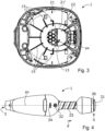
- Fig. 3 illustrates a third cross section of the vacuum cleaner 1 illustrated in Fig. 1 and Fig. 2 .
- the third cross section of Fig. 3 is made in a plane perpendicular to the fan axis ax at the first portion 21 of the sound reducing section 13.
- each blade 15 of the set of blades 15 protrudes into the sound reducing section 13 in a direction parallel to the fan axis ax.
- vortex flow of air is efficiently counteracted when the air is flowing from the first portion 21 into the second portion 22 via the narrowing portion 21'.
- a vacuum cleaner 1 is provided having conditions and characteristics suitable for being manufactured in a cost-efficient manner.
- Fig. 4 illustrates a top view of a vacuum cleaner 1 according to the embodiments illustrated in Fig. 1 - Fig. 3 .
- the vacuum cleaner 1 comprises an activation button 32 and a battery level indicator 34.
- Fig. 1 - Fig. 4 outer surfaces 25 of the second portion 22 of the sound reducing section 13 form a handle for a user of the handheld vacuum cleaner 1.
- the length L3 of the second portion 22, measured in a direction d coinciding with the fan axis ax is sufficient for accommodating at least four fingers of a hand of a user.
- the length L3 of the second portion 22, measured in a direction d coinciding with the fan axis ax is more than 3 cm, or more than 5 cm.
- a vacuum cleaner 1 is provided having a well-balanced weight distribution, which facilitates use of the vacuum cleaner 1.
- the third portion 23 comprises the air outlet 5.
- the air outlet 5 comprises a shield 31.
- the shield 31 is configured to direct the air flowing through the air outlet 5 to directions d2 being angled relative to the fan axis ax, as indicated in Fig. 1 and Fig. 2 .
- the shield 31 is configured to direct the air to substantially radial directions d2 relative to the fan axis ax. Due to these features, the noise generated by the vacuum cleaner 1 is further attenuated and the air flowing through the air outlet 5 will cause less disturbance to a user of the vacuum cleaner 1. Furthermore, as indicated in Fig.
- the vacuum cleaner 1 comprises a section 36 blocking air from flowing towards the top side of the vacuum cleaner 1, wherein the top side of the vacuum cleaner 1 is the side that faces the forearm of the user when the user grips the handle of the vacuum cleaner 1 in an intended grip direction.
- the top side of the vacuum cleaner 1 comprises the activation button 32 and the battery level indicator 34. Due to the section 36 blocking air from flowing towards the top side of the vacuum cleaner 1, the air flowing through the air outlet 5 will cause even less disturbance to a user of the vacuum cleaner 1.
- the vacuum cleaner 1 may comprise at least one sound absorbing unit 33, 35 provided in a sound absorbing material arranged in the sound reducing section 13.
- the vacuum cleaner 1 comprises a sound absorbing unit 33 provided in a sound absorbing material arranged in the second portion 22 of the sound reducing section 13, and a sound absorbing unit 35 provided in a sound absorbing material arranged in the third portion 23 of the sound reducing section 13.
- the sound absorbing units 33, 35 may each be provided in an air permeable material, such as a foam material.
- the sound absorbing units 33, 35 may also be a surface coating on the inside of any of the first to third portions 21,22,23 of the sound reduction section 13. Due to the sound absorbing units 33, 35, the noise generated by the vacuum cleaner 1 is attenuated in a further efficient manner.
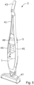
- Fig. 5 illustrates a vacuum cleaner 2 according to some embodiments of the present disclosure.
- the vacuum cleaner 2 illustrated in Fig. 5 is a stick-type vacuum cleaner 2.
- the vacuum cleaner 2 comprises a shaft part 41 and a detachable handheld vacuum cleaner 1 according to the embodiments illustrated in Fig. 1 - Fig. 4 .
- the shaft part 41 comprises a handle 43, two tube parts 45, a floor nozzle 47, and a holder 49 for the handheld vacuum cleaner 1 arranged between the two tube parts 45.
- the handheld vacuum cleaner 1 is attached to the holder 49 of the vacuum cleaner 2. When in this position, the air inlet of the handheld vacuum cleaner 1 is fluidly connected to the floor nozzle 47.
- the air outlet 5 of the handheld vacuum cleaner 1 is positioned between the two tube parts 45 when the handheld vacuum cleaner 1 is attached to the holder 49. In this manner, the air flowing through the air outlet 5 will cause less disturbance to a user of the vacuum cleaner 2 while allowing a low flow resistance of air flowing through the air outlet 5 of the handheld vacuum cleaner 1.
Landscapes
- Engineering & Computer Science (AREA)
- Mechanical Engineering (AREA)
- Electric Suction Cleaners (AREA)
Description
- The present disclosure relates to a handheld vacuum cleaner. The present disclosure further relates to a vacuum cleaner comprising a holder for a handheld vacuum cleaner.
- A vacuum cleaner is a device that uses an air pump, most often a centrifugal fan, to create a partial vacuum in order to suck up dust and dirt from surfaces, such as floors, carpets, and the like. Different kinds of vacuum cleaners are known. Among them, upright/stick type vacuum cleaners and handheld vacuum cleaners. These types of vacuum cleaner generally have an elongated body with a nozzle in one end and a handle in the other end. A housing with a fan and filter may be attached to the elongated body and may extend substantially in parallel thereto. Such a housing may comprise a fan and motor, a dust collector, a filter, and other necessary parts.
- Handheld vacuum cleaners and upright/stick type vacuum cleaners allow a user to remove dust and debris in a relatively easy and efficient manner and may be operated with a single hand grip. Handheld vacuum cleaners have become increasingly popular. Reasons for this might be that they are simple to use and require little space when not in use.
- In general, some problems and requirements exist when designing vacuum cleaners. One example is the cleaning efficiency. Users of vacuum cleaners expect a high cleaning efficiency in order to achieve a good cleaning result with little effort. Another problem is noise level during operation. Noise generated by a vacuum cleaner is usually annoying for the user and for persons in the vicinity of the vacuum cleaner. Still another problem is to provide a user-friendly vacuum cleaner which can be used in a simple and intuitive manner. A further problem is energy consumption of the vacuum cleaner. These problems and requirements are usually conflicting problems and requirements. That is, an easy way to increase the cleaning efficiency of a vacuum cleaner is to increase the power of the fan. However, as a result thereof, the noise generated by the vacuum cleaner as well as the energy consumption of the vacuum cleaner will increase.
- Moreover, generally, on today's consumer market, it is an advantage if products, such as vacuum cleaners and vacuum cleaner components, have conditions and/or characteristics suitable for being manufactured and assembled in a cost-efficient manner. To be inserted on
page 1,line 34 of original description. - Document
WO2014/056686 A1 discloses an exhaust grille comprising an array of spaced vanes. The grill is configured so as to deflect sound waves incident upon the grille to prevent them from passing through the exhaust grille. - Document
WO2018/065069 A1 discloses a stick vacuum cleaner having a handheld vacuum cleaner adapted to be docked to a stick. When the handheld vacuum cleaner is docked to the stick an air path is formed connecting an air outlet of the handheld vacuum cleaner with an air outlet provided in the stick. A noise absorption unit is provided in the air path or outside the air outlet from the stick. - Document
GB2468299 A - Document
CN108903792 A discloses dust collector and a noise reduction structure. A noise reduction sleeve is installed at a tail of the motor cover, and a mazy air-out structure is formed between the noise reduction sleeve and the motor cover to reduce the noise. - Document
KR20070032443 A - Document
WO2017/092832 A1 discloses a vacuum cleaner comprising a motor housing providing a wall structure having a plurality of walls and defining an air flow channel with a plurality of turns. - It is an object of the present invention to overcome, or at least alleviate, at least some of the above-mentioned problems and drawbacks.
- According to a first aspect of the invention, the object is achieved by a handheld vacuum cleaner according to the
independent claim 1. - Since the vacuum cleaner comprises a sound reducing section extending from the fan in the extension direction, and since the angle between the extension direction and the fan axis is less than 45 degrees, the noise generated by the fan is attenuated in an efficient manner. Thereby, a vacuum cleaner is provided having conditions for generating less noise during operation, and conditions for increased power levels of the fan while generating less noise.
- Furthermore, since the angle between the extension direction of the sound reducing section and the fan axis is less than 45 degrees, a low flow resistance of air flowing through the sound reducing section can be provided while obtaining an efficient attenuation of the noise generated by the fan. Moreover, since the angle between the extension direction of the sound reducing section and the fan axis is less than 45 degrees, conditions are provided for a vacuum cleaner having a well-balanced weight distribution, which facilitates use of the vacuum cleaner, as is further explained herein.
- Accordingly, a handheld vacuum cleaner is provided overcoming, or at least alleviating, at least some of the above-mentioned problems and drawbacks. As a result, the above-mentioned object is achieved.
- Optionally, the length of the sound reducing section is greater than 5 cm. Thereby, a vacuum cleaner is provided having conditions for generating less noise during operation, and conditions for increased power levels of the fan while generating less noise. Furthermore, a low flow resistance of air flowing through the sound reducing section can be provided while obtaining an efficient attenuation of the noise generated by the vacuum cleaner. Moreover, conditions are provided for a well-balanced vacuum cleaner.
- Optionally, the length of the sound reducing section is at least 20%, or at least 30%, of the distance between the air inlet and the air outlet of the vacuum cleaner. Thereby, a vacuum cleaner is provided having conditions for generating less noise during operation, and conditions for increased power levels of the fan while generating less noise. Furthermore, a low flow resistance of air flowing through the sound reducing section can be provided while obtaining an efficient attenuation of the noise generated by the vacuum cleaner. Moreover, conditions are provided for a well-balanced vacuum cleaner.
- Optionally, the sound reducing section comprises one or more blades protruding into the sound reducing section so as to counteract vortex flow of air in the sound reducing section. Thereby, the flow resistance of air flowing through the sound reducing section is significantly reduced. As a result, the energy consumption of the vacuum cleaner can be lowered while allowing higher power levels of the fan. Moreover, due to the one or more blades protruding into the sound reducing section, the sound generated by the vacuum cleaner can be further lowered. This because turbulent flow of air in the sound reducing section is significantly lowered.
- Optionally, each blade of the one or more blades protrudes in a direction parallel to the fan axis. Thereby, vortex flow of air in the sound reducing section is counteracted in an efficient manner. Moreover, the one or more blades have conditions and characteristics suitable for being manufactured in a cost-efficient manner.
- In the invention the sound reducing section comprises a first portion and a second portion downstream of the first portion, and wherein a cross sectional area of the second portion is smaller than the cross sectional area of the first portion. Thereby, the noise generated by the vacuum cleaner is attenuated in a further efficient manner.
- Optionally, the cross sectional area of the second portion is at least 30% smaller than the cross sectional area of the first portion. Thereby, it is ensured that the noise generated by the vacuum cleaner is attenuated in a further efficient manner.
- Optionally, the one or more blades is/are arranged upstream of the second portion. Thereby, vortex flow of air in the second portion of the sound reducing section is counteracted in an efficient manner. As a result thereof, the flow resistance of air flowing through the second portion of the sound reducing section is significantly reduced. As a result, the energy consumption of the vacuum cleaner can be lowered while allowing higher power levels of the fan. As a further result of these features, the sound generated by the vacuum cleaner is further lowered.
- Optionally, the sound reducing section comprises a narrowing portion between the first and second portions. Thereby, the noise generated by the fan is attenuated in a further efficient manner.
- Optionally, the one or more blades is/are arranged in, or upstream of, the narrowing portion. Thereby, vortex flow of air in the narrowing portion, and in the second portion downstream of the narrowing portion of the sound reducing section, is counteracted in an efficient manner. As a result thereof, the flow resistance of air flowing through the narrowing portion, and through the second portion downstream of the narrowing portion of the sound reducing section, is significantly reduced. As a result, the energy consumption of the vacuum cleaner can be lowered while allowing higher power levels of the fan. As a further result of these features, the sound generated by the vacuum cleaner is further lowered.
- Optionally, the sound reducing section comprises a third portion downstream of the second portion, and wherein the cross sectional area of the third portion is greater than the cross sectional area of the second portion. Thereby, the noise generated by the fan is attenuated in a further efficient manner, while allowing a low flow resistance of air flowing through the sound reducing section. Moreover, conditions are provided for a well-balanced vacuum cleaner.
- Optionally, the cross sectional area of the third portion is at least 30% greater than the cross sectional area of the second portion. Thereby, it is ensured that the noise generated by the fan is attenuated in a further efficient manner, while allowing a low flow resistance of air flowing through the sound reducing section. Moreover, conditions are provided for a well-balanced vacuum cleaner, as is further explained herein.
- Optionally, the length of the second portion, measured in a direction coinciding with the fan axis, is more than 3 cm, or more than 5 cm. Thereby, it is ensured that the noise generated by the fan is attenuated in an efficient manner while allowing a low flow resistance of air flowing through the sound reducing section. Moreover, conditions are provided for a well-balanced vacuum cleaner, as is further explained herein.
- Optionally, outer surfaces of the second portion form a handle for a user of the handheld vacuum cleaner. Thereby, a vacuum cleaner is provided in which a portion of the sound reducing section forms a handle for a user of the handheld vacuum cleaner. As a result thereof, a vacuum cleaner is provided having conditions for generating less noise during operation while having conditions and characteristics suitable for being manufactured and assembled in a cost-efficient manner. Moreover, a vacuum cleaner is provided having conditions for a compact and well-balanced design, as is further explained herein.
- Optionally, the vacuum cleaner comprises a motor configured to rotate the fan around the fan axis, and wherein the motor is arranged in the first portion of the sound reducing section. Thereby, the motor is cooled in an efficient manner by the air flowing through the sound reducing section during operation of the vacuum cleaner. Accordingly, a vacuum cleaner is provided having conditions for generating less noise during operation while having conditions and characteristics suitable for being manufactured and assembled in a cost-efficient manner. Moreover, a vacuum cleaner is provided having conditions for a compact and well-balanced design.
- Optionally, the vacuum cleaner comprises a battery configured to provide electricity to the motor, and wherein the battery is arranged in the third portion of the sound reducing section. Thereby, the battery is cooled in an efficient manner by the air flowing through the sound reducing section during operation of the vacuum cleaner. Accordingly, a user-friendly vacuum cleaner is provided having conditions for generating less noise during operation while having conditions and characteristics suitable for being manufactured and assembled in a cost-efficient manner. Moreover, a vacuum cleaner is provided having conditions for a compact and well-balanced design.
- Optionally, the third portion comprises the air outlet. Thereby, a vacuum cleaner is provided having conditions for generating less noise during operation.
- Optionally, the air outlet comprises a shield. Thereby, the noise generated by the vacuum cleaner is attenuated in a further efficient manner while allowing a low flow resistance of air flowing through the sound reducing section.
- Optionally, the shield is configured to direct the air to directions being angled relative to the fan axis. Thereby, the noise generated by the vacuum cleaner is attenuated in a further efficient manner while allowing a low flow resistance of air flowing through the sound reducing section. Moreover, conditions are provided for directing the air flowing through the air outlet in directions causing less disturbance to a user of the vacuum cleaner.
- Optionally, the shield is configured to direct the air to substantially radial directions relative to the fan axis. Thereby, the noise generated by the vacuum cleaner is attenuated in a further efficient manner while allowing a low flow resistance of air flowing through the sound reducing section. Moreover, conditions are provided for directing the air flowing through the air outlet in directions causing less disturbance to a user of the vacuum cleaner.
- Optionally, the vacuum cleaner comprises at least one sound absorbing unit provided in a sound absorbing material arranged in the sound reducing section, preferably an air permeable sound absorbing material or a sound absorbing surface coating. Thereby, the noise generated by the vacuum cleaner is attenuated in a further efficient manner while allowing a low flow resistance of air flowing through the sound reducing section.
- Optionally, the vacuum cleaner comprises at least one sound absorbing unit provided in a sound absorbing material arranged in the second portion of the sound reducing section, preferably an air permeable sound absorbing material or a sound absorbing surface coating. Thereby, the noise generated by the vacuum cleaner is attenuated in a still further efficient manner while allowing a low flow resistance of air flowing through the sound reducing section.
- Optionally, the vacuum cleaner comprises at least one sound absorbing unit provided in a sound absorbing material arranged in the third portion of the sound reducing section, preferably an air permeable sound absorbing material or a sound absorbing surface coating. Thereby, the noise generated by the vacuum cleaner is attenuated in a still further efficient manner while allowing a low flow resistance of air flowing through the sound reducing section.
- Optionally, the angle between the extension direction of the sound reducing section and the fan axis is less than 25 degrees, or less than 10 degrees, or around 0 degrees.
- Optionally, the vacuum cleaner may comprise a shaft part and a detachable handheld vacuum cleaner according to some embodiments of the present disclosure, wherein the shaft part comprises a handle, two tube parts, a floor nozzle, and a holder for the handheld vacuum cleaner arranged between the two tube parts.
- Since the vacuum cleaner comprises a detachable handheld vacuum cleaner according to some embodiments, a vacuum cleaner is provided having conditions for generating less noise during operation, and conditions for increased power levels of the fan while generating less noise. Furthermore, since the sound reducing section of the handheld vacuum cleaner extends from the fan in an extension direction, and wherein the angle between the extension direction and the fan axis is less than 45 degrees, a low flow resistance of air flowing through the sound reducing section can be provided while obtaining an efficient attenuation of the noise generated by the fan of the handheld vacuum cleaner.
- Accordingly, a vacuum cleaner is provided overcoming, or at least alleviating, at least some of the above-mentioned problems and drawbacks. As a result, the above-mentioned object is achieved.
- Optionally, the air outlet of the handheld vacuum cleaner is positioned between the two tube parts when the handheld vacuum cleaner is attached to the holder. Thereby, conditions are provided for directing the air flowing through the air outlet in directions causing less disturbance to a user of the vacuum cleaner while allowing a low flow resistance of air flowing through the air outlet of the handheld vacuum cleaner.
- Further features of, and advantages with, the present invention will become apparent when studying the appended claims and the following detailed description.
- Various aspects of the invention, including its particular features and advantages, will be readily understood from the example embodiments discussed in the following detailed description and the accompanying drawings, in which:
-
Fig. 1 illustrates a first cross section of a handheld vacuum cleaner according to some embodiments, -
Fig. 2 illustrates a second cross section of the vacuum cleaner illustrated inFig. 1 with some components removed, -
Fig. 3 illustrates a third cross section of the vacuum cleaner illustrated inFig. 1 andFig. 2 , -
Fig. 4 illustrates a top view of a vacuum cleaner according to the embodiments illustrated inFig. 1 - Fig. 3 , and -
Fig. 5 illustrates a vacuum cleaner according to some further embodiments of the present disclosure. - Aspects of the present invention will now be described more fully. Like numbers refer to like elements throughout. Well-known functions or constructions will not necessarily be described in detail for brevity and/or clarity.
-
Fig. 1 illustrates a first cross section of ahandheld vacuum cleaner 1 according to some embodiments. For the reason of brevity and clarity, thehandheld vacuum cleaner 1 is in some places herein referred to as "the vacuum cleaner". Thevacuum cleaner 1 comprises anair inlet 3, anair outlet 5, and afan 7. Thefan 7 is powered by anelectric motor 27. Theelectric motor 27 is configured to rotate thefan 7 around a fan axis ax. The cross section ofFig. 1 is made through a plane comprising the fan axis ax. Thefan 7 is configured to rotate around the fan axis ax to create an air flow through anair flow path 9. Theair flow path 9 extends from theair inlet 3 to theair outlet 5. Theelectric motor 27 may comprise ball bearings and may be rubber suspended relative a housing 6 of thevacuum cleaner 1. In this manner, less noise is generated during operation of thevacuum cleaner 1. - The
vacuum cleaner 1 further comprises aseparation device 11 arranged in theair flow path 9. Theseparation device 11 is configured to separate dust from air flowing through theair flow path 9. Theseparation device 11 may comprise a dust bag, a filter, a cyclone separator, or the like. - The
air flow path 9 comprises asound reducing section 13 arranged downstream of thefan 7. As can be seen inFig. 1 , thesound reducing section 13 extends from thefan 7 in an extension direction d. According to the illustrated embodiments, thesound reducing section 13 is substantially concentric to the fan axis ax. According to further embodiments, the angle a1 between the extension direction d of thesound reducing section 13 and the fan axis ax may be less than 45 degrees, or less than 25 degrees, or less than 10 degrees, or around 0 degrees. Due to these features, as is further explained herein, the noise generated by thefan 7 and theelectric motor 27 is attenuated in an efficient manner. Moreover, as is further explained herein, conditions are provided for a user-friendly vacuum cleaner 1 having a balanced weight distribution. The feature that thesound reducing section 13 is substantially concentric to the fan axis ax, as mentioned herein, may encompass that a distance between the fan axis ax and thesound reducing section 13 is less than 5 cm along the extent of thesound reducing section 13. Moreover, the feature that thesound reducing section 13 is substantially concentric to the fan axis ax may encompass that the angle between the fan axis ax and the extent of thesound reducing section 13 is less than 10 degrees. - According to the illustrated embodiments, the length L1 of the
sound reducing section 13 is approximately 53.5% of the distance L2 between theair inlet 3 and theair outlet 5 of thevacuum cleaner 1. According to further embodiments, the length L1 of thesound reducing section 13 may be at least 10%, at least 20%, or at least 30%, of the distance L2 between theair inlet 3 and theair outlet 5 of thevacuum cleaner 1. According to some embodiments, the length L1 of thesound reducing section 13 is greater than 5 cm, or greater than 7 cm. Thereby, the noise generated by thefan 7 and theelectric motor 27 can be attenuated in an efficient manner while allowing a low flow resistance of air flowing through thesound reducing section 13. Moreover, as is further explained herein, conditions are provided for a user-friendly vacuum cleaner 1 having a balanced weight distribution. - The
sound reducing section 13 comprises afirst portion 21 and asecond portion 22 downstream of thefirst portion 21. Moreover, thesound reducing section 13 comprises a narrowing portion 21' between the first andsecond portions sound reducing section 13 comprises athird portion 23 downstream of thesecond portion 22. According to the illustrated embodiments, thesound reducing section 13, and theportions vacuum cleaner 1. The housing 6 may be provided in a polymeric material. - As can be seen in
Fig. 1 , the cross sectional area A2 of thesecond portion 22 is smaller than the cross sectional area A1 of thefirst portion 21. According to the illustrated embodiments, the cross sectional area A1 of thefirst portion 21 is approximately 9 045 mm2 and the cross sectional area A2 of thesecond portion 22 is approximately 910 mm2. According to further embodiments, the cross sectional area A1 of thefirst portion 21 may be within the range of 8 000 - 12 000 mm2, and the cross sectional area A2 of thesecond portion 22 may be within the range of 700 - 1500 mm2. According to some embodiments, the cross sectional area A2 of thesecond portion 22 may be at least 30% smaller than the cross sectional area A1 of thefirst portion 21. - Moreover, as can be seen in
Fig. 1 , the cross sectional area A3 of thethird portion 23 is greater than the cross sectional area A2 of thesecond portion 22. According to the illustrated embodiments, the cross sectional area A3 of thethird portion 23 is approximately 6 901 mm2. According to further embodiments, the cross sectional area A3 of thethird portion 23 may be within the range of 4 500 - 9 000 mm2. According to some embodiments, the cross sectional area A3 of thethird portion 23 may be at least 30 % greater than the cross sectional area A2 of thesecond portion 22. - According to the illustrated embodiments, the
motor 27 is arranged in thefirst portion 21 of thesound reducing section 13. Moreover, thevacuum cleaner 1 comprises abattery 29 configured to provide electricity to themotor 27. As can be seen inFig. 1 , thebattery 29 is arranged in thethird portion 23 of thesound reducing section 13. Thevacuum cleaner 1 compriseselectrical wires 28 for transferring electricity between thebattery 29 and themotor 27. Theelectrical wires 28 extends through thesecond portion 22 of thesound reducing section 13. -
Fig. 2 illustrates a second cross section of thevacuum cleaner 1 illustrated inFig. 1 with some components removed to provide a better view of thesound reducing section 13 and the features thereof. As indicated inFig. 2 , thesound reducing section 13 comprises a set ofblades 15 protruding into thesound reducing section 13. Theblades 15 are configured to counteract vortex flow of air in thesound reducing section 13. According to the illustrated embodiments, theblades 15 of the set ofblades 15 are arranged upstream of thesecond portion 22 and upstream of the narrowing portion 21'. According to further embodiments, theblades 15 of the set ofblades 15 may be arranged in, or upstream of, the narrowing portion 21'. In this manner, vortex flow of air in thesecond portion 22 of thesound reducing section 13 is counteracted in an efficient manner. -
Fig. 3 illustrates a third cross section of thevacuum cleaner 1 illustrated inFig. 1 andFig. 2 . The third cross section ofFig. 3 is made in a plane perpendicular to the fan axis ax at thefirst portion 21 of thesound reducing section 13. As best seen inFig. 3 , eachblade 15 of the set ofblades 15 protrudes into thesound reducing section 13 in a direction parallel to the fan axis ax. In this manner, vortex flow of air is efficiently counteracted when the air is flowing from thefirst portion 21 into thesecond portion 22 via the narrowing portion 21'. Moreover, since eachblade 15 of the set ofblades 15 protrudes into thesound reducing section 13 in a direction parallel to the fan axis ax, avacuum cleaner 1 is provided having conditions and characteristics suitable for being manufactured in a cost-efficient manner. -
Fig. 4 illustrates a top view of avacuum cleaner 1 according to the embodiments illustrated inFig. 1 - Fig. 3 . As seen inFig. 4 , thevacuum cleaner 1 comprises anactivation button 32 and abattery level indicator 34. Below, simultaneous reference is made toFig. 1 - Fig. 4 . As is indicated inFig. 4 , as well as inFig. 1 andFig. 2 ,outer surfaces 25 of thesecond portion 22 of thesound reducing section 13 form a handle for a user of thehandheld vacuum cleaner 1. According to the illustrated embodiments, the length L3 of thesecond portion 22, measured in a direction d coinciding with the fan axis ax, is sufficient for accommodating at least four fingers of a hand of a user. According to some embodiments, the length L3 of thesecond portion 22, measured in a direction d coinciding with the fan axis ax, is more than 3 cm, or more than 5 cm. - Since the
outer surfaces 25 of thesecond portion 22 form a handle for a user of thehandheld vacuum cleaner 1, and since thebattery 29 is arranged in thethird portion 23 of thesound reducing section 13 and themotor 27 is arranged in thefirst portion 21 of thesound reducing section 13, avacuum cleaner 1 is provided having a well-balanced weight distribution, which facilitates use of thevacuum cleaner 1. - As indicated in
Fig. 1 ,Fig. 2 , andFig. 3 , thethird portion 23 comprises theair outlet 5. Moreover, according to the illustrated embodiments, theair outlet 5 comprises ashield 31. Theshield 31 is configured to direct the air flowing through theair outlet 5 to directions d2 being angled relative to the fan axis ax, as indicated inFig. 1 andFig. 2 . According to the illustrated embodiments, theshield 31 is configured to direct the air to substantially radial directions d2 relative to the fan axis ax. Due to these features, the noise generated by thevacuum cleaner 1 is further attenuated and the air flowing through theair outlet 5 will cause less disturbance to a user of thevacuum cleaner 1. Furthermore, as indicated inFig. 4 , according to the illustrated embodiments, thevacuum cleaner 1 comprises asection 36 blocking air from flowing towards the top side of thevacuum cleaner 1, wherein the top side of thevacuum cleaner 1 is the side that faces the forearm of the user when the user grips the handle of thevacuum cleaner 1 in an intended grip direction. Moreover, the top side of thevacuum cleaner 1 comprises theactivation button 32 and thebattery level indicator 34. Due to thesection 36 blocking air from flowing towards the top side of thevacuum cleaner 1, the air flowing through theair outlet 5 will cause even less disturbance to a user of thevacuum cleaner 1. - As indicated in
Fig. 2 , thevacuum cleaner 1 may comprise at least onesound absorbing unit sound reducing section 13. According to the illustrated embodiments, thevacuum cleaner 1 comprises asound absorbing unit 33 provided in a sound absorbing material arranged in thesecond portion 22 of thesound reducing section 13, and asound absorbing unit 35 provided in a sound absorbing material arranged in thethird portion 23 of thesound reducing section 13. Thesound absorbing units sound absorbing units third portions sound reduction section 13. Due to thesound absorbing units vacuum cleaner 1 is attenuated in a further efficient manner. -
Fig. 5 illustrates avacuum cleaner 2 according to some embodiments of the present disclosure. Thevacuum cleaner 2 illustrated inFig. 5 is a stick-type vacuum cleaner 2. Thevacuum cleaner 2 comprises ashaft part 41 and a detachablehandheld vacuum cleaner 1 according to the embodiments illustrated inFig. 1 - Fig. 4 . Theshaft part 41 comprises ahandle 43, twotube parts 45, afloor nozzle 47, and aholder 49 for thehandheld vacuum cleaner 1 arranged between the twotube parts 45. InFig. 5 , thehandheld vacuum cleaner 1 is attached to theholder 49 of thevacuum cleaner 2. When in this position, the air inlet of thehandheld vacuum cleaner 1 is fluidly connected to thefloor nozzle 47. - As seen in
Fig. 5 , theair outlet 5 of thehandheld vacuum cleaner 1 is positioned between the twotube parts 45 when thehandheld vacuum cleaner 1 is attached to theholder 49. In this manner, the air flowing through theair outlet 5 will cause less disturbance to a user of thevacuum cleaner 2 while allowing a low flow resistance of air flowing through theair outlet 5 of thehandheld vacuum cleaner 1. - It is to be understood that the foregoing is illustrative of various example embodiments and that the invention is defined only by the appended claims. A person skilled in the art will realize that the example embodiments may be modified, and that different features of the example embodiments may be combined to create embodiments other than those described herein, without departing from the scope of the present invention, as defined by the appended claims.
- As used herein, the term "comprising" or "comprises" is open-ended, and includes one or more stated features, elements, steps, components, or functions but does not preclude the presence or addition of one or more other features, elements, steps, components, functions, or groups thereof.
Claims (18)
- A handheld vacuum cleaner (1) comprising:- an air inlet (3),- an air outlet (5),- a fan (7) configured to rotate around a fan axis (ax) to create an air flow through an air flow path (9) extending from the air inlet (3) to the air outlet (5), and- a separation device (11) arranged in the air flow path (9), the separation device (11) being configured to separate dust from air flowing through the air flow path (9),wherein the air flow path (9) comprises a sound reducing section (13) extending from the fan (7) in an extension direction (d), and wherein the angle (a1) between the extension direction (d) and the fan axis (ax) is less than 45 degreescharacterized in thatthe sound reducing section (13) comprises a first portion (21) and a second portion (22) downstream of the first portion (21), and wherein a cross sectional area (A2) of the second portion (22) is smaller than the cross sectional area (A1) of the first portion (21).
- The vacuum cleaner (1) according to claim 1, wherein the length (L1) of the sound reducing section (13) is greater than 5 cm.
- The vacuum cleaner (1) according to claim 1 or 2, wherein the length (L1) of the sound reducing section (13) is at least 20%, or at least 30%, of the distance (L2) between the air inlet (3) and the air outlet (5) of the vacuum cleaner (1).
- The vacuum cleaner (1) according to any one of the preceding claims, wherein the sound reducing section (13) comprises one or more blades (15) protruding into the sound reducing section (13) so as to counteract vortex flow of air in the sound reducing section (13).
- The vacuum cleaner (1) according to claim 4, wherein each blade (15) of the one or more blades (15) protrudes in a direction parallel to the fan axis (ax).
- The vacuum cleaner (1) according to claim 1 , wherein the cross sectional area (A2) of the second portion (22) is at least 30% smaller than the cross sectional area (A1) of the first portion (21).
- The vacuum cleaner (1) according to claim 4 or 5 and any one of the claims 1 and 6, wherein the one or more blades (15) is/are arranged upstream of the second portion (22).
- The vacuum cleaner (1) according to any one of the claims 1 or 6 - 7, wherein the sound reducing section (13) comprises a narrowing portion (21') between the first and second portions (21, 22).
- The vacuum cleaner (1) according to claim 8 and any one of the claims 4 and 5,
wherein the one or more blades (15) is/are arranged in, or upstream of, the narrowing portion (21'). - The vacuum cleaner (1) according to any one of the claims 1 or 6 - 9, wherein the sound reducing section (13) comprises a third portion (23) downstream of the second portion (22), and wherein the cross sectional area (A3) of the third portion (23) is greater than the cross sectional area (A2) of the second portion (22).
- The vacuum cleaner (1) according to claim 10, wherein the cross sectional area (A3) of the third portion (23) is at least 30 % greater than the cross sectional area (A2) of the second portion (22).
- The vacuum cleaner (1) according to any one of the claims 1 or 6 - 11, wherein the length (L3) of the second portion (22), measured in a direction (d) coinciding with the fan axis (ax), is more than 3 cm, or more than 5 cm.
- The vacuum cleaner (1) according to any one of the claims 1 or 6 - 12, wherein outer surfaces (25) of the second portion (22) form a handle for a user of the handheld vacuum cleaner (1).
- The vacuum cleaner (1) according to any one of the claims 1 or 6 - 13, wherein the vacuum cleaner (1) comprises a motor (27) configured to rotate the fan (7) around the fan axis (ax), and wherein the motor (27) is arranged in the first portion (21).
- The vacuum cleaner (1) according to claim 14 and any one of the claims 10 and 11, wherein the vacuum cleaner (1) comprises a battery (29) configured to provide electricity to the motor (27), and wherein the battery (29) is arranged in the third portion (23).
- The vacuum cleaner (1) according to claim 10, 11 or 15, wherein the third portion (23) comprises the air outlet (5).
- The vacuum cleaner (1) according to any one of the preceding claims, wherein the vacuum cleaner (1) comprises at least one sound absorbing unit (33, 35) provided in a sound absorbing material arranged in the sound reducing section (13), preferably an air permeable sound absorbing material or a sound absorbing surface coating.
- A vacuum cleaner (2) comprising a shaft part (41) and a detachable handheld vacuum cleaner (1) according to any of preceding claims, wherein the shaft part (41) comprises a handle (43), two tube parts (45), a floor nozzle (47), and a holder (49) for the handheld vacuum cleaner (1) arranged between the two tube parts (45).
Applications Claiming Priority (1)
| Application Number | Priority Date | Filing Date | Title |
|---|---|---|---|
| PCT/EP2019/068267 WO2021004618A1 (en) | 2019-07-08 | 2019-07-08 | Handheld vacuum cleaner, and vacuum cleaner comprising a handheld vacuum cleaner |
Publications (2)
| Publication Number | Publication Date |
|---|---|
| EP3996563A1 EP3996563A1 (en) | 2022-05-18 |
| EP3996563B1 true EP3996563B1 (en) | 2024-11-20 |
Family
ID=67226252
Family Applications (1)
| Application Number | Title | Priority Date | Filing Date |
|---|---|---|---|
| EP19737720.3A Active EP3996563B1 (en) | 2019-07-08 | 2019-07-08 | Handheld vacuum cleaner, and vacuum cleaner comprising a handheld vacuum cleaner |
Country Status (6)
| Country | Link |
|---|---|
| US (1) | US20220273146A1 (en) |
| EP (1) | EP3996563B1 (en) |
| JP (1) | JP7485468B2 (en) |
| KR (1) | KR102718625B1 (en) |
| CN (1) | CN114040698A (en) |
| WO (1) | WO2021004618A1 (en) |
Families Citing this family (5)
| Publication number | Priority date | Publication date | Assignee | Title |
|---|---|---|---|---|
| DE102020134579A1 (en) * | 2020-12-22 | 2022-06-23 | Vorwerk & Co. Interholding Gesellschaft mit beschränkter Haftung | Household appliance with a fan and a flow duct |
| JP7784327B2 (en) * | 2022-03-08 | 2025-12-11 | 日立グローバルライフソリューションズ株式会社 | Vacuum cleaners and silencer units for vacuum cleaners |
| USD1084568S1 (en) * | 2023-09-22 | 2025-07-15 | Jinsai Zhang | Cordless vacuum cleaner |
| USD1120540S1 (en) * | 2023-11-17 | 2026-03-24 | Halo Appliances Ltd | Vacuum cleaner with accessible battery and dirt bag |
| SE2430495A1 (en) * | 2024-09-27 | 2026-03-28 | Electrolux Ab | Low noise suction nozzle for vacuum cleaner |
Family Cites Families (28)
| Publication number | Priority date | Publication date | Assignee | Title |
|---|---|---|---|---|
| JPS5990741U (en) * | 1982-08-20 | 1984-06-20 | 三洋電機株式会社 | Hand-operated small vacuum cleaner |
| JPH0517005Y2 (en) * | 1985-09-20 | 1993-05-07 | ||
| JPH0713623Y2 (en) * | 1987-07-24 | 1995-04-05 | 三洋電機株式会社 | Cordless cleaner |
| JPH0473030A (en) * | 1990-07-16 | 1992-03-09 | Matsushita Electric Ind Co Ltd | vacuum cleaner |
| JP2001218706A (en) * | 2000-02-14 | 2001-08-14 | Matsushita Electric Ind Co Ltd | Electric vacuum cleaner |
| JP2002355196A (en) * | 2001-05-31 | 2002-12-10 | Matsushita Electric Ind Co Ltd | Electric vacuum cleaner |
| JP2003245226A (en) * | 2002-02-27 | 2003-09-02 | Toshiba Tec Corp | Vacuum cleaner, its main body, extension pipe, dust collection hose and suction port body |
| US7159273B2 (en) * | 2003-04-17 | 2007-01-09 | The Hoover Company | Muffler assembly for a bagless vacuum cleaner |
| CN1565368A (en) * | 2003-06-23 | 2005-01-19 | 乐金电子(天津)电器有限公司 | Dust collector |
| KR20070032443A (en) * | 2005-09-16 | 2007-03-22 | 삼성광주전자 주식회사 | Suction nozzle of vacuum cleaner |
| KR100809738B1 (en) * | 2007-03-12 | 2008-03-06 | 삼성광주전자 주식회사 | Vacuum cleaner |
| GB2468299B (en) * | 2009-03-03 | 2012-06-20 | Dyson Technology Ltd | Noise reduction arrangement for a cleaning appliance. |
| US8448291B2 (en) * | 2009-03-11 | 2013-05-28 | G.B.D. Corp. | Inlet for a vacuum cleaner |
| KR101198522B1 (en) * | 2010-12-21 | 2012-11-06 | 엘지전자 주식회사 | Vacuum cleaner |
| US20120186036A1 (en) * | 2011-01-25 | 2012-07-26 | Kegg Steven W | Diffuser for a vacuum cleaner motor-fan assembly |
| RU2563787C1 (en) * | 2012-10-09 | 2015-09-20 | Конинклейке Филипс Н.В. | Exhaust grille |
| GB2513661B (en) * | 2013-05-03 | 2016-03-16 | Dyson Technology Ltd | Vibration isolation mount |
| CN106068090B (en) * | 2014-03-07 | 2019-03-08 | 创科地板护理技术有限公司 | Surface cleaning device |
| KR20160079277A (en) * | 2014-12-26 | 2016-07-06 | 삼성전자주식회사 | Vacuum cleaner and control method for the same |
| CN206538723U (en) * | 2015-04-10 | 2017-10-03 | 苏州宝时得电动工具有限公司 | Suction and blowing device |
| JP2017006284A (en) * | 2015-06-19 | 2017-01-12 | 日本電産株式会社 | Drier |
| CN108366704A (en) * | 2015-12-04 | 2018-08-03 | 伊莱克斯公司 | Vacuum cleaner |
| AU2017101264A4 (en) * | 2016-09-29 | 2017-10-26 | Bissell Inc. | Vacuum cleaner |
| CN109843132B (en) * | 2016-10-07 | 2021-09-10 | 伊莱克斯公司 | Low noise stick vacuum cleaner |
| JP2018064849A (en) * | 2016-10-21 | 2018-04-26 | 日本電産株式会社 | Motor module and vacuum cleaner |
| CN108903792B (en) * | 2018-08-29 | 2024-03-26 | 宁波富佳实业股份有限公司 | Noise reduction structure of dust collector |
| US20220125267A1 (en) * | 2018-12-13 | 2022-04-28 | Koki Holdings Co., Ltd. | Cleaner |
| EP3738494A1 (en) * | 2019-05-14 | 2020-11-18 | Koninklijke Philips N.V. | Noise reduction device |
-
2019
- 2019-07-08 EP EP19737720.3A patent/EP3996563B1/en active Active
- 2019-07-08 WO PCT/EP2019/068267 patent/WO2021004618A1/en not_active Ceased
- 2019-07-08 US US17/624,907 patent/US20220273146A1/en not_active Abandoned
- 2019-07-08 CN CN201980098116.4A patent/CN114040698A/en active Pending
- 2019-07-08 KR KR1020227001770A patent/KR102718625B1/en active Active
- 2019-07-08 JP JP2021577136A patent/JP7485468B2/en active Active
Also Published As
| Publication number | Publication date |
|---|---|
| JP2022539743A (en) | 2022-09-13 |
| US20220273146A1 (en) | 2022-09-01 |
| KR20220031021A (en) | 2022-03-11 |
| EP3996563A1 (en) | 2022-05-18 |
| WO2021004618A1 (en) | 2021-01-14 |
| KR102718625B1 (en) | 2024-10-16 |
| CN114040698A (en) | 2022-02-11 |
| JP7485468B2 (en) | 2024-05-16 |
Similar Documents
| Publication | Publication Date | Title |
|---|---|---|
| EP4255271B1 (en) | Vacuum cleaner | |
| US20220273146A1 (en) | Handheld vacuum cleaner, and vacuum cleaner comprising a handheld vacuum cleaner | |
| US8397344B2 (en) | Cleaning appliance | |
| CN101583302B (en) | Improvements on Airflow Losses in Vacuum Collectors | |
| KR102061517B1 (en) | Cleaner | |
| CN203879800U (en) | Power tool | |
| CN215777744U (en) | Vacuum cleaner with a vacuum cleaner head | |
| AU2005327466B2 (en) | Removable internal air diffuser | |
| WO2012103053A2 (en) | Diffuser for a vacuum cleaner motor-fan assembly | |
| US20070243087A1 (en) | Electric motor housing | |
| CN211511630U (en) | Household dust collector | |
| US20200154964A1 (en) | Low noise stick vacuum cleaner | |
| EP4262502B1 (en) | Vacuum cleaner | |
| CN217645111U (en) | Dirt cup subassembly and surface cleaning equipment | |
| CN111588303B (en) | Vacuum cleaner | |
| EP4615292A1 (en) | Vacuum cleaner | |
| JP2011074869A (en) | Electric blower | |
| JP2017051387A (en) | Vacuum cleaner |
Legal Events
| Date | Code | Title | Description |
|---|---|---|---|
| STAA | Information on the status of an ep patent application or granted ep patent |
Free format text: STATUS: UNKNOWN |
|
| STAA | Information on the status of an ep patent application or granted ep patent |
Free format text: STATUS: THE INTERNATIONAL PUBLICATION HAS BEEN MADE |
|
| PUAI | Public reference made under article 153(3) epc to a published international application that has entered the european phase |
Free format text: ORIGINAL CODE: 0009012 |
|
| STAA | Information on the status of an ep patent application or granted ep patent |
Free format text: STATUS: REQUEST FOR EXAMINATION WAS MADE |
|
| 17P | Request for examination filed |
Effective date: 20220208 |
|
| AK | Designated contracting states |
Kind code of ref document: A1 Designated state(s): AL AT BE BG CH CY CZ DE DK EE ES FI FR GB GR HR HU IE IS IT LI LT LU LV MC MK MT NL NO PL PT RO RS SE SI SK SM TR |
|
| DAV | Request for validation of the european patent (deleted) | ||
| DAX | Request for extension of the european patent (deleted) | ||
| GRAP | Despatch of communication of intention to grant a patent |
Free format text: ORIGINAL CODE: EPIDOSNIGR1 |
|
| STAA | Information on the status of an ep patent application or granted ep patent |
Free format text: STATUS: GRANT OF PATENT IS INTENDED |
|
| INTG | Intention to grant announced |
Effective date: 20240318 |
|
| P01 | Opt-out of the competence of the unified patent court (upc) registered |
Effective date: 20240517 |
|
| GRAS | Grant fee paid |
Free format text: ORIGINAL CODE: EPIDOSNIGR3 |
|
| GRAA | (expected) grant |
Free format text: ORIGINAL CODE: 0009210 |
|
| STAA | Information on the status of an ep patent application or granted ep patent |
Free format text: STATUS: THE PATENT HAS BEEN GRANTED |
|
| AK | Designated contracting states |
Kind code of ref document: B1 Designated state(s): AL AT BE BG CH CY CZ DE DK EE ES FI FR GB GR HR HU IE IS IT LI LT LU LV MC MK MT NL NO PL PT RO RS SE SI SK SM TR |
|
| REG | Reference to a national code |
Ref country code: GB Ref legal event code: FG4D |
|
| REG | Reference to a national code |
Ref country code: CH Ref legal event code: EP |
|
| REG | Reference to a national code |
Ref country code: DE Ref legal event code: R096 Ref document number: 602019062226 Country of ref document: DE |
|
| REG | Reference to a national code |
Ref country code: IE Ref legal event code: FG4D |
|
| REG | Reference to a national code |
Ref country code: LT Ref legal event code: MG9D |
|
| REG | Reference to a national code |
Ref country code: NL Ref legal event code: MP Effective date: 20241120 |
|
| PG25 | Lapsed in a contracting state [announced via postgrant information from national office to epo] |
Ref country code: HR Free format text: LAPSE BECAUSE OF FAILURE TO SUBMIT A TRANSLATION OF THE DESCRIPTION OR TO PAY THE FEE WITHIN THE PRESCRIBED TIME-LIMIT Effective date: 20241120 Ref country code: IS Free format text: LAPSE BECAUSE OF FAILURE TO SUBMIT A TRANSLATION OF THE DESCRIPTION OR TO PAY THE FEE WITHIN THE PRESCRIBED TIME-LIMIT Effective date: 20250320 Ref country code: PT Free format text: LAPSE BECAUSE OF FAILURE TO SUBMIT A TRANSLATION OF THE DESCRIPTION OR TO PAY THE FEE WITHIN THE PRESCRIBED TIME-LIMIT Effective date: 20250320 |
|
| PG25 | Lapsed in a contracting state [announced via postgrant information from national office to epo] |
Ref country code: FI Free format text: LAPSE BECAUSE OF FAILURE TO SUBMIT A TRANSLATION OF THE DESCRIPTION OR TO PAY THE FEE WITHIN THE PRESCRIBED TIME-LIMIT Effective date: 20241120 Ref country code: NL Free format text: LAPSE BECAUSE OF FAILURE TO SUBMIT A TRANSLATION OF THE DESCRIPTION OR TO PAY THE FEE WITHIN THE PRESCRIBED TIME-LIMIT Effective date: 20241120 |
|
| REG | Reference to a national code |
Ref country code: AT Ref legal event code: MK05 Ref document number: 1742769 Country of ref document: AT Kind code of ref document: T Effective date: 20241120 |
|
| PG25 | Lapsed in a contracting state [announced via postgrant information from national office to epo] |
Ref country code: BG Free format text: LAPSE BECAUSE OF FAILURE TO SUBMIT A TRANSLATION OF THE DESCRIPTION OR TO PAY THE FEE WITHIN THE PRESCRIBED TIME-LIMIT Effective date: 20241120 |
|
| PG25 | Lapsed in a contracting state [announced via postgrant information from national office to epo] |
Ref country code: ES Free format text: LAPSE BECAUSE OF FAILURE TO SUBMIT A TRANSLATION OF THE DESCRIPTION OR TO PAY THE FEE WITHIN THE PRESCRIBED TIME-LIMIT Effective date: 20241120 |
|
| PG25 | Lapsed in a contracting state [announced via postgrant information from national office to epo] |
Ref country code: NO Free format text: LAPSE BECAUSE OF FAILURE TO SUBMIT A TRANSLATION OF THE DESCRIPTION OR TO PAY THE FEE WITHIN THE PRESCRIBED TIME-LIMIT Effective date: 20250220 |
|
| PG25 | Lapsed in a contracting state [announced via postgrant information from national office to epo] |
Ref country code: LV Free format text: LAPSE BECAUSE OF FAILURE TO SUBMIT A TRANSLATION OF THE DESCRIPTION OR TO PAY THE FEE WITHIN THE PRESCRIBED TIME-LIMIT Effective date: 20241120 Ref country code: GR Free format text: LAPSE BECAUSE OF FAILURE TO SUBMIT A TRANSLATION OF THE DESCRIPTION OR TO PAY THE FEE WITHIN THE PRESCRIBED TIME-LIMIT Effective date: 20250221 Ref country code: AT Free format text: LAPSE BECAUSE OF FAILURE TO SUBMIT A TRANSLATION OF THE DESCRIPTION OR TO PAY THE FEE WITHIN THE PRESCRIBED TIME-LIMIT Effective date: 20241120 |
|
| PG25 | Lapsed in a contracting state [announced via postgrant information from national office to epo] |
Ref country code: PL Free format text: LAPSE BECAUSE OF FAILURE TO SUBMIT A TRANSLATION OF THE DESCRIPTION OR TO PAY THE FEE WITHIN THE PRESCRIBED TIME-LIMIT Effective date: 20241120 |
|
| PG25 | Lapsed in a contracting state [announced via postgrant information from national office to epo] |
Ref country code: RS Free format text: LAPSE BECAUSE OF FAILURE TO SUBMIT A TRANSLATION OF THE DESCRIPTION OR TO PAY THE FEE WITHIN THE PRESCRIBED TIME-LIMIT Effective date: 20250220 |
|
| PG25 | Lapsed in a contracting state [announced via postgrant information from national office to epo] |
Ref country code: SM Free format text: LAPSE BECAUSE OF FAILURE TO SUBMIT A TRANSLATION OF THE DESCRIPTION OR TO PAY THE FEE WITHIN THE PRESCRIBED TIME-LIMIT Effective date: 20241120 |
|
| PG25 | Lapsed in a contracting state [announced via postgrant information from national office to epo] |
Ref country code: DK Free format text: LAPSE BECAUSE OF FAILURE TO SUBMIT A TRANSLATION OF THE DESCRIPTION OR TO PAY THE FEE WITHIN THE PRESCRIBED TIME-LIMIT Effective date: 20241120 |
|
| PG25 | Lapsed in a contracting state [announced via postgrant information from national office to epo] |
Ref country code: EE Free format text: LAPSE BECAUSE OF FAILURE TO SUBMIT A TRANSLATION OF THE DESCRIPTION OR TO PAY THE FEE WITHIN THE PRESCRIBED TIME-LIMIT Effective date: 20241120 |
|
| PG25 | Lapsed in a contracting state [announced via postgrant information from national office to epo] |
Ref country code: RO Free format text: LAPSE BECAUSE OF FAILURE TO SUBMIT A TRANSLATION OF THE DESCRIPTION OR TO PAY THE FEE WITHIN THE PRESCRIBED TIME-LIMIT Effective date: 20241120 |
|
| PG25 | Lapsed in a contracting state [announced via postgrant information from national office to epo] |
Ref country code: SK Free format text: LAPSE BECAUSE OF FAILURE TO SUBMIT A TRANSLATION OF THE DESCRIPTION OR TO PAY THE FEE WITHIN THE PRESCRIBED TIME-LIMIT Effective date: 20241120 |
|
| PG25 | Lapsed in a contracting state [announced via postgrant information from national office to epo] |
Ref country code: CZ Free format text: LAPSE BECAUSE OF FAILURE TO SUBMIT A TRANSLATION OF THE DESCRIPTION OR TO PAY THE FEE WITHIN THE PRESCRIBED TIME-LIMIT Effective date: 20241120 |
|
| PG25 | Lapsed in a contracting state [announced via postgrant information from national office to epo] |
Ref country code: IT Free format text: LAPSE BECAUSE OF FAILURE TO SUBMIT A TRANSLATION OF THE DESCRIPTION OR TO PAY THE FEE WITHIN THE PRESCRIBED TIME-LIMIT Effective date: 20241120 |
|
| REG | Reference to a national code |
Ref country code: DE Ref legal event code: R097 Ref document number: 602019062226 Country of ref document: DE |
|
| PG25 | Lapsed in a contracting state [announced via postgrant information from national office to epo] |
Ref country code: SE Free format text: LAPSE BECAUSE OF FAILURE TO SUBMIT A TRANSLATION OF THE DESCRIPTION OR TO PAY THE FEE WITHIN THE PRESCRIBED TIME-LIMIT Effective date: 20241120 |
|
| PLBE | No opposition filed within time limit |
Free format text: ORIGINAL CODE: 0009261 |
|
| STAA | Information on the status of an ep patent application or granted ep patent |
Free format text: STATUS: NO OPPOSITION FILED WITHIN TIME LIMIT |
|
| PGFP | Annual fee paid to national office [announced via postgrant information from national office to epo] |
Ref country code: DE Payment date: 20250728 Year of fee payment: 7 |
|
| PGFP | Annual fee paid to national office [announced via postgrant information from national office to epo] |
Ref country code: GB Payment date: 20250722 Year of fee payment: 7 |
|
| PGFP | Annual fee paid to national office [announced via postgrant information from national office to epo] |
Ref country code: FR Payment date: 20250725 Year of fee payment: 7 |
|
| 26N | No opposition filed |
Effective date: 20250821 |
|
| REG | Reference to a national code |
Ref country code: CH Ref legal event code: H13 Free format text: ST27 STATUS EVENT CODE: U-0-0-H10-H13 (AS PROVIDED BY THE NATIONAL OFFICE) Effective date: 20260224 |
|
| PG25 | Lapsed in a contracting state [announced via postgrant information from national office to epo] |
Ref country code: LU Free format text: LAPSE BECAUSE OF NON-PAYMENT OF DUE FEES Effective date: 20250708 |
|
| REG | Reference to a national code |
Ref country code: BE Ref legal event code: MM Effective date: 20250731 |
|
| PG25 | Lapsed in a contracting state [announced via postgrant information from national office to epo] |
Ref country code: BE Free format text: LAPSE BECAUSE OF NON-PAYMENT OF DUE FEES Effective date: 20250731 |
|
| PG25 | Lapsed in a contracting state [announced via postgrant information from national office to epo] |
Ref country code: CH Free format text: LAPSE BECAUSE OF NON-PAYMENT OF DUE FEES Effective date: 20250731 |
|
| PG25 | Lapsed in a contracting state [announced via postgrant information from national office to epo] |
Ref country code: LT Free format text: LAPSE BECAUSE OF FAILURE TO SUBMIT A TRANSLATION OF THE DESCRIPTION OR TO PAY THE FEE WITHIN THE PRESCRIBED TIME-LIMIT Effective date: 20241120 |
|
| PG25 | Lapsed in a contracting state [announced via postgrant information from national office to epo] |
Ref country code: IE Free format text: LAPSE BECAUSE OF NON-PAYMENT OF DUE FEES Effective date: 20250708 |
|
| PG25 | Lapsed in a contracting state [announced via postgrant information from national office to epo] |
Ref country code: MC Free format text: LAPSE BECAUSE OF FAILURE TO SUBMIT A TRANSLATION OF THE DESCRIPTION OR TO PAY THE FEE WITHIN THE PRESCRIBED TIME-LIMIT Effective date: 20241120 |
|
| PG25 | Lapsed in a contracting state [announced via postgrant information from national office to epo] |
Ref country code: CY Free format text: LAPSE BECAUSE OF FAILURE TO SUBMIT A TRANSLATION OF THE DESCRIPTION OR TO PAY THE FEE WITHIN THE PRESCRIBED TIME-LIMIT Effective date: 20241120 |