EP3996347A1 - Multi-access edge computing device and network access control method - Google Patents
Multi-access edge computing device and network access control method Download PDFInfo
- Publication number
- EP3996347A1 EP3996347A1 EP21154110.7A EP21154110A EP3996347A1 EP 3996347 A1 EP3996347 A1 EP 3996347A1 EP 21154110 A EP21154110 A EP 21154110A EP 3996347 A1 EP3996347 A1 EP 3996347A1
- Authority
- EP
- European Patent Office
- Prior art keywords
- network
- user device
- address
- access
- module
- Prior art date
- Legal status (The legal status is an assumption and is not a legal conclusion. Google has not performed a legal analysis and makes no representation as to the accuracy of the status listed.)
- Granted
Links
Images


Classifications
-
- H—ELECTRICITY
- H04—ELECTRIC COMMUNICATION TECHNIQUE
- H04L—TRANSMISSION OF DIGITAL INFORMATION, e.g. TELEGRAPHIC COMMUNICATION
- H04L61/00—Network arrangements, protocols or services for addressing or naming
- H04L61/50—Address allocation
- H04L61/5046—Resolving address allocation conflicts; Testing of addresses
-
- H—ELECTRICITY
- H04—ELECTRIC COMMUNICATION TECHNIQUE
- H04L—TRANSMISSION OF DIGITAL INFORMATION, e.g. TELEGRAPHIC COMMUNICATION
- H04L45/00—Routing or path finding of packets in data switching networks
- H04L45/74—Address processing for routing
- H04L45/745—Address table lookup; Address filtering
-
- H—ELECTRICITY
- H04—ELECTRIC COMMUNICATION TECHNIQUE
- H04L—TRANSMISSION OF DIGITAL INFORMATION, e.g. TELEGRAPHIC COMMUNICATION
- H04L61/00—Network arrangements, protocols or services for addressing or naming
- H04L61/50—Address allocation
- H04L61/5007—Internet protocol [IP] addresses
-
- H—ELECTRICITY
- H04—ELECTRIC COMMUNICATION TECHNIQUE
- H04L—TRANSMISSION OF DIGITAL INFORMATION, e.g. TELEGRAPHIC COMMUNICATION
- H04L61/00—Network arrangements, protocols or services for addressing or naming
- H04L61/50—Address allocation
- H04L61/5061—Pools of addresses
-
- H—ELECTRICITY
- H04—ELECTRIC COMMUNICATION TECHNIQUE
- H04W—WIRELESS COMMUNICATION NETWORKS
- H04W24/00—Supervisory, monitoring or testing arrangements
- H04W24/02—Arrangements for optimising operational condition
-
- H—ELECTRICITY
- H04—ELECTRIC COMMUNICATION TECHNIQUE
- H04W—WIRELESS COMMUNICATION NETWORKS
- H04W8/00—Network data management
- H04W8/26—Network addressing or numbering for mobility support
-
- H—ELECTRICITY
- H04—ELECTRIC COMMUNICATION TECHNIQUE
- H04W—WIRELESS COMMUNICATION NETWORKS
- H04W48/00—Access restriction; Network selection; Access point selection
- H04W48/18—Selecting a network or a communication service
-
- H—ELECTRICITY
- H04—ELECTRIC COMMUNICATION TECHNIQUE
- H04W—WIRELESS COMMUNICATION NETWORKS
- H04W84/00—Network topologies
- H04W84/02—Hierarchically pre-organised networks, e.g. paging networks, cellular networks, WLAN [Wireless Local Area Network] or WLL [Wireless Local Loop]
- H04W84/10—Small scale networks; Flat hierarchical networks
- H04W84/12—WLAN [Wireless Local Area Networks]
-
- H—ELECTRICITY
- H04—ELECTRIC COMMUNICATION TECHNIQUE
- H04W—WIRELESS COMMUNICATION NETWORKS
- H04W88/00—Devices specially adapted for wireless communication networks, e.g. terminals, base stations or access point devices
- H04W88/16—Gateway arrangements
Definitions
- This disclosure relates to a network communication control device, and particularly to a multi-access edge computing (MEC) device.
- MEC multi-access edge computing
- Wi-Fi network has usually been set up, and even a mobile network is introduced, to allow a user device to access the Wi-Fi network and the mobile network which have different radio access technologies (RATs).
- RATs radio access technologies
- the Wi-Fi network and the mobile network each have their own methods for assigning IP addresses, and in order to avoid conflicts between the assigned IP addresses, two non-overlapping IP pools are usually configured for the Wi-Fi network and the mobile network. Therefore, when a user device is in the coverage of different RATs while using the network service of the application provided by a company, different IP addresses respectively for RATs are assigned to the user device, and accordingly, the connection of the service must be interrupted.
- the disclosure provides a multi-access edge computing (MEC) device and network access control method.
- MEC multi-access edge computing
- a multi-access edge computing device is configured to be connected to a first network and a second network that have different radio access technologies, and comprises a routing module, a comparison module and a control module wherein the control module is connected to the routing module and the comparison module.
- the routing module is configured to temporarily store a data packet.
- the comparison module stores a user device identity and address comparison table.
- the control module is configured to perform steps when determining that a user device is connected to the first network and intends to switch to the second network, wherein the steps comprise: according to identity information of the user device, looking up a target address in the user device identity and address comparison table, notifying the routing module to temporarily store a data packet corresponding to the user device and the first network, notifying the user device to release an original used address on an interface of the first network and then assigning the target address to an interface of the second network of the user device, and transmitting the data packet that is temporarily stored to the interface of the second network of the user device.
- the target address is identical to the original used address.
- a network access control method is applied to a multi-access edge computing device, wherein the multi-access edge computing device is configured to be connected to a first network and a second network that have different radio access technologies.
- the network access control method comprises: determining that a user device is connected to the first network and intends to switch to the second network; according to identity information of the user device, looking up a target address in a user device identity and address comparison table, and temporarily storing a data packet corresponding to the user device and the first network; notifying the user device to release an original used address on an interface of the first network and then assigning the target address to an interface of the second network of the user device, wherein the target address is identical to the original used address; and transmitting the data packet that is temporarily stored to the interface of the second network of the user device.
- the multi-access edge computing device and the network access control method provided in this disclosure can allow a user device to always hold the same IP address as it needs to switch the connected network due to movement, thereby avoiding service connection interruption.
- the multi-access edge computing device and the network access control method provided in this disclosure may avoid the loss of data packets.
- FIG. 1 a schematic diagram of a communication environment of a multi-access edge computing device according to an embodiment of this disclosure.
- the multi-access edge computing device 1 can be connected to a first network 2a and a second network 2b, and can be connected to a user device 3. More particularly, the multi-access edge computing device 1 can be connected to the first network 2a, the second network 2b and the user device 3 by a wireless connection module 11.
- the first network 2a and the second network 2b have different radio access technologies.
- the communication environment shown in FIG. 1 belongs to a heterogeneous network.
- one of the first network 2a and the second network 2b is Wi-Fi network
- the other one is a mobile network that is also called cellular network, such as 4G network, 5G network, etc.
- the user device 3 is, for example, a mobile electronic device such as smart phone, tablet, laptop, etc., and can be connected to the first network 2a and the second network 2b.
- the multi-access edge computing device 1 comprises a persistent IP dispatcher (PIPD) that can manage the assignment of IP addresses in a unified manner.
- the PIPD comprises a routing module 12, a comparison module 13 and a control module 14, wherein the control module 14 is connected to the routing module 12 and the comparison module 13.
- the routing module 12 can be connected to a wireless connection module 11 and an APP backend, and execute a routing rule: transmitting a data packet to the destination according to one or more characteristics of the header of the data packet. More particularly, the routing module 12 can transmit data packets from the APP backend to the user device 3 through the first network 2a and the second network 2b by the wireless connection module 11.
- the routing module 12 can also be controlled by the control module 14 to temporarily store one or more data packets.
- the comparison module 13 stores a user device identity and address comparison table.
- the user device identity and address comparison table stores identity information of user devices and the IP addresses of user devices.
- the identity information of the user device can be a subscriber permanent identifier (SUPI) or a unique symbol for the user device.
- the comparison module 13 can return the IP address corresponding to the identity information of a specific user device provided by the control module according to the above-mentioned comparison table. If the comparison module 13 determines that this user device has not been assigned a dedicated IP address (e.g.
- the comparison module 13 can select an unused IP address from an IP pool as the dedicated IP address of this specific user device, record the dedicated address and the identity information of this specific user device and their relationship in the comparison table, and return the dedicated IP address to the control module 14. Moreover, when the remaining available capacity (storage space) of the comparison table or the IP pool is less than a preset threshold, the comparison module 13 can clear the records that have not been used for a long time (e.g. the identity information and dedicated IP address of a user device that has not been connected to any RAT for a preset time); or, the comparison module 13 can regularly clear said records that have not been used for a long time.
- the control module 14 is configured to perform several steps when determining that the user device 3 that is connected to the first network 2a intends to switch to the second network 2b, and said several steps comprises: according to identity information of the user device 3, looking up a target address in the user device identity and address comparison table, and notifying the routing module 12 to temporarily store one or more data packets corresponding to the user device 3 and the first network 2a; notifying the user device 3 to release an original used address on the interface of the first network 2a, and then assigning the target address to the interface of the second network 2b of the user device 3; and transmitting the one or more data packets temporarily stored by the routing module 12 to the interface of the second network 2b of the user device 3.
- the target address is identical to the original used address.
- FIG. 2 is a function block diagram of a multi-access edge computing device according to an embodiment of this disclosure.
- the wireless connection module 11 of the multi-access edge computing device 1 can comprise a Wi-Fi gateway (GW) 111 and a user plan function module (UPF) 112.
- the multi-access edge computing device 1 can be connected to a Wi-Fi access point (AP) by the Wi-Fi GW 111, and connected to the user device 3 through the Wi-Fi AP.
- AP Wi-Fi access point
- the multi-access edge computing device 1 can be connected to a session management function module (SMF) in a mobile network (especially 5G Core) by the UPF 112, and also connected to the user device 3 through a base station (gNB) by the UPF 112.
- SMF session management function module
- the user device 3 can be connected to an access management function module (AMF) in the mobile network through the base station. More particularly, the user device 3 can be registered with 5G Core through the AMF, and later, when the user device 3 requests to transmit packets through the mobile network, the SMF can authenticate the identity information of the user device 3 and then establish a protocol data unit session (PDU session).
- SMF session management function module
- PDU session protocol data unit session
- the control module 14 of the multi-access edge computing device 1 can comprise a session management sub-module (SM) 141 and an address assignment sub-module 142. More particularly, the SM 141 can determine whether an access request signal received from the user device 3 is through the Wi-Fi GW 111 or the UPF 112 of the wireless connection module 11 according to the media access control (MAC) address of the packet of the access request signal, and accordingly determine the network to which the user device 3 intends to be connected. The SM 141 can also send a disconnect signal to instruct the user device 3 to release the IP address on the interface of a specific network.
- MAC media access control
- the method for releasing the IP address of the user device 3 on the Wi-Fi interface is that the SM 141 instructs the Wi-Fi GW 111 to send a disassociation frame signal to the user device 3, and the method for releasing the IP address of the user device 3 on the 5G interface is that the SM141 instructs the UPF 112 to send a PDU session release signal to the SMF in the 5G Core.
- the SM 141 can also transfer the signals generated by the address assignment sub-module 142.
- the address assignment sub-module 142 is configured to look up the target IP address corresponding to the user device 3 in the user device identity and address comparison table based on the access request signal of the user device 3, and transmit an access acceptance signal to the SM 141 after obtaining the target IP address corresponding to the user device 3, wherein the access acceptance signal includes the target IP address.
- the address assignment sub-module 142 can be an application function (AF) sub-module, an authentication authorization accounting (AAA) proxy sub-module or a mobile edge computing AAA (MEC AAA) sub-module.
- the AF sub-module is used when the SMF of the 5G Core is set to obtain the IP address corresponding to the user device 3 in the 5G Core;
- the AAA proxy sub-module is used when the SMF of the 5G Core is set to obtain the IP address corresponding to the user device 3 from a data network and an AAA server exists in the network field (data network);
- the MEC AAA sub-module is used when the SMF of the 5G Core is set to obtain the IP address corresponding to the user device 3 from the data network and there is no AAA server existing in the network field (data network).
- the functions of these three sub-modules are further described below.
- the functions of the AF sub-module include: connecting to the 5G Core, and informing the SMF, through a policy control function (PCF) module in the 5G Core, that the SMF should obtain the IP address corresponding to the user device 3 from an external IP pool; serving as the external IP pool of the SMF; as receiving an access request signal from the Wi-Fi GW 111, asking an authentication server function module (AUSF) in the 5G Core to authenticate the identity information of the user device 3; and generating an access acceptance signal according to the target IP address obtained from the user device identity and address comparison table, and transmitting the access acceptance signal to the SM 141 to assign the target IP address.
- PCF policy control function
- the functions of the AAA proxy sub-module include: analyzing the user identity (SUPI) from the access request signal; transferring the access request signal to the AAA server in the network field (data network); and receiving an access acceptance signal from the AAA server in the network field (data network) wherein the access acceptance signal is in response to the access request signal, overwriting the content (e.g. value) of an address field (Framed-IP-Address field) in the access acceptance signal with the target IP address obtained from the user device identity and address comparison table, and then transmitting the modified access acceptance signal to the SM 141 to assign the target IP address.
- SUPI user identity
- the functions of the MEC AAA sub-module include: storing the identity (SUPI), authentication parameters or other information of the user device(s) in the network field; generating an access acceptance signal, wherein the content (e.g. value) of a Framed-IP-Address field in the access acceptance signal is the target IP address obtained from the user device identity and address comparison table, and then transmitting the access acceptance signal to the SM 141 to assign the target IP address.
- identity identity
- authentication parameters or other information of the user device(s) in the network field generating an access acceptance signal, wherein the content (e.g. value) of a Framed-IP-Address field in the access acceptance signal is the target IP address obtained from the user device identity and address comparison table, and then transmitting the access acceptance signal to the SM 141 to assign the target IP address.
- FIG. 2 exemplarily illustrates the control module 14 of the multi-access edge computing device 1 includes one address assignment sub-module 142, but in other embodiments, the control module of the multi-access edge computing device can include two or three address assignment sub-modules that are two or three of the above-mentioned AF sub-module, AAA proxy sub-module and MEC AAA sub-module, and can be selectively enabled based on the usage environment of the multi-access edge computing device. For example, when the usage environment conforms to the timing of using AF sub-module as aforementioned (i.e. when the SMF of the 5G Core is set to obtain the IP address corresponding to the user device 3 in the 5G Core), the AF sub-module is enabled and the other sub-modules are not enabled.
- AF sub-module is enabled and the other sub-modules are not enabled.
- the multi-access edge computing device 1 can comprise a memory and a processor, wherein the processor is electrically connected to the memory.
- the memory is, for example, a flash memory, a read-only memory, a magnetic random access memory or other non-volatile storage medium.
- the memory stores the aforementioned user device identity and address comparison table and multiple instructions, wherein said multiple instructions at least include the instructions corresponding to the operations of the modules of the multi-access edge computing device 1 described in the above embodiments and the network access control method described in the following embodiments.
- the processor is, for example, a central processing unit, a microcontroller, a programmable logic controller, etc.
- the processor can execute the instructions stored in the memory so as to perform the operations of each module.
- the modules included in the multi-access edge computing device 1 as aforementioned are servers independently set up and connected to each other, or applications running on one or more servers.
- This disclosure also provides a network access control method applied to a multi-access edge computing device. More particularly, the network access control method can be the method of the multi-access edge computing device 1 connecting the user device 3 to the first network 2a or the second network 2b in the aforementioned embodiment.
- FIG. 3 is a flow chart of a network access control method according to an embodiment of this disclosure.
- the network access control method shown in FIG. 3 is exemplarily described using the communication environment of the multi-access edge computing device 1 shown in FIG. 1 . As shown in FIG.
- the network access control method comprises step S10: determining that a user device 3 is connected to the first network 2a and intends to switch to the second network 2b; step S11: according to identity information of the user device 3, looking up a target address in a user device identity and address comparison table, and temporarily storing a data packet corresponding to the user device 3 and the first network 2a; step S12: notifying the user device 3 to release an original used address on an interface of the first network 2a and then assigning the target address to an interface of the second network 2b of the user device 3, wherein the target address is identical to the original used address; step S13: transmitting the data packet that is temporarily stored to the interface of the second network 2b of the user device 3.
- steps S10, S12 and S13 can be performed by the control module 14 of the multi-access edge computing device 1, and in step S11, the control module 14 of the multi-access edge computing device 1 can send an inquiry about the address corresponding to the identity information of the user device 3 to the comparison module 13, take the response from the comparison module 13 as the target address, and notify the routing module 12 to temporarily store the data packet(s) corresponding to the user device 3 and the first network 2a.
- the network access control method can further comprise the IP address assignment for the situation in which the user device 3 is not connected to any network currently or has not been assigned any IP address.
- FIG. 4 is a flow chart of a network access control method according to another embodiment of this disclosure. As shown in FIG.
- the network access control method can comprise step S20: receiving a request for access to network X from user device; step S21: recognizing the identity of the user device; step S22: determining whether the user device currently holds the address of another network Y; when the determined result of step S22 is "yes", performing step S23: starting to temporarily store one or more data packets from network Y; step S24: notifying the user device to release the address on the interface of network Y; step S25: assigning the dedicated address to the interface of network X of the user device; step S26: transmitting the one or more data packets temporarily stored to the interface of network X of the user device; when the determined result of step S22 is "no", performing step S27: determining whether the user device has been assigned a dedicated address; when the determined result of step S27 is "no", performing step S28: generating and recording the dedicated address of the user device; and after step S28 is performed or when the determined result of step S27 is "yes", performing step S29: assigning the dedicated address to
- the control module 14 receives a request for access to network X from the user device 3. More particularly, the SM 141 of the control module 14 can determine whether an access request signal received from the user device 3 is through the Wi-Fi GW 111 or the UPF 112 of the wireless connection module 11 according to the MAC address of the packet of the access request signal, and accordingly determine whether network X is Wi-Fi network or a mobile network. In step S21, the control module 14 recognizes the identity of the user device 3.
- the address assignment sub-module 142 of the control module 14 firstly analyzes the user identity (SUPI) in this signal, and then uses this SUPI to ask an authentication server function module (AUSF) in the 5G Core to authenticate the identity of the user device 3.
- SUPI user identity
- AUSF authentication server function module
- the control module 14 determines whether the user device 3 currently holds the address of another network Y. More particularly, in the control module 14, the address assignment sub-module 142 confirms to the session management sub-module 141 whether the last connected network of the user device 3 is different from the network to be connected.
- step S22 When the determined result of step S22 is "yes", the control module 14 notifies the routing module 12 to start to temporarily store one or more packets from network Y (step S23). More particularly, the control module 14 notifies the routing module 12 by the session management sub-module 141. In steps S24-S26, the control module 14 notifies the user device 3 to release the address on the interface of network Y, assigns the dedicated address to the interface of network X of the user device 3, and then transmits the one or more packets temporarily stored to the interface of network X of the user device 3. More particularly, the control module 14 performs steps S24-S26 by the session management sub-module 141, and the dedicated address is obtained by consulting the user device identity and address comparison table by the address assignment sub-module 142.
- step S10 in FIG. 1 can include steps S20-S22 in FIG. 2 , wherein the determined result of step S22 is "yes";
- step S11 in FIG. 1 can include step S23 in FIG. 2 ;
- step S12 in FIG. 1 can include steps S24 and S25 in FIG. 2 ;
- step S13 in FIG. 1 corresponds to step S26 in FIG. 2 .
- step S22 When the determined result of step S22 is "no", which indicates that the user device 3 is not connected to any network at that time, the control module 14 consults the comparison module 13 to instruct the comparison module 13 to determine whether the user device 3 has been assigned a dedicated address according to the identity information of the user device 3 and the user device identity and address comparison table (step S27). When the determined result of step S27 is "no" (e.g. no record about the user device 3 found in the comparison table), the comparison module 13 generates a dedicated address for the user device 3 and records this dedicated address (step S28).
- the comparison module 13 can select an unused IP address from the IP pool as the above-mentioned dedicated address, record this dedicated address, the identity information of the user device 3, and the correspondence between the two in the user device identity and address comparison table, and return the dedicated address to the control module 14.
- the control module 14 assigns the dedicated address to the interface of network X of the user device 3.
- the determined result of step S27 is "yes" (e.g. the dedicated address of the user device 3 is stored in the comparison table)
- the comparison module 13 returns the dedicated address of the user device 3 to the control module 14, and then the control module 14 assigns the dedicated address to the interface of network X of the user device 3.
- the address assignment sub-module 142 of the control module 14 of the multi-access edge computing device 1 can include one or more of the AF sub-module, the AAA proxy sub-module and the MEC AAA sub-module which are used at different timings.
- the following further describes the signal transmission of three embodiments of the network access control method in which the above-mentioned three types of sub-modules respectively participate.
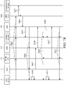
- FIGs. 5A and 5B schematic diagrams of signal transmission of a network access control method according to an embodiment of this disclosure.
- the user device 3, the Wi-Fi GW 111, the UPF 112, the routing module 12, the SM 141 and the comparison module 13 shown in FIGs. 5A and 5B are the same as the modules/sub-modules with the same symbols in FIGs. 1 and 2 , and a AF 142a (AF sub-module) serves as the address assignment sub-module in FIG. 2 , wherein the functions of each of the modules/sub-modules and the connections therebetween are as described in the aforementioned embodiments, and are not repeated here.
- 5GC 2 represents the 5G Core, and includes modules such as SMF, AMF, AUSF, PCF, etc. as described in the aforementioned embodiments.
- FIG. 5A illustrates the switching process of the user device 3 from the Wi-Fi network to the 5G network.
- the user device 3 requests an IP address of the 5G interface from the 5GC 2. More particularly, the user device 3 can send an access request signal including the identity information of the user device 3 to the 5GC 2.
- the SMF in the 5GC 2 establishes a PDU session according to the request from the user device 3, and requests an IP address for access to the 5G network from the AF 142a (i.e. transmitting the access request signal to the AF 142a).
- the AF 142a is set to be an external IP pool of the SMF in the 5GC 2 in advance, and therefore, when the SMF in the 5GC 2 receives the request from the user device 3, the SMF requests an IP address from the AF 142a according to the setting.
- the AF 142a consults the user device identity and address comparison table in the comparison module 13 according to the identity information of the user device 3 included in the access request signal to obtain the target IP address corresponding to the identity information of the user device 3.
- the AF 142a notifies the SM 141 that the user device 3 is about to access the 5G network. More particularly, the AF 142a generates an access acceptance signal including the target IP address and transmits the access acceptance signal to the SM 141.
- the SM 141 controls the routing module 12 to start to temporarily store data packet(s) according to the access acceptance signal. More particularly, the data packet temporarily stored by the routing module 12 is the data packet that the APP backend originally intends to transmit to the user device 3 through the Wi-Fi network.
- the SM 141 transmits a signal to the Wi-Fi GW 111 to send a disconnect signal to the user device 3 by a management interface of Wi-Fi, wherein the disconnect signal is a disassociation frame signal, which is a standard signal defined by Wi-Fi access technology.
- the user device 3 releases the IP address on the Wi-Fi interface according to the disconnect signal.
- the Wi-Fi GW 111 reports to the SM 141 that the original used IP address on the original network interface is released.
- the SM 141 sends the access acceptance signal to the user device 3 through the routing module 12, the UPF 112 and the 5GC 2 according to the report from the Wi-Fi GW 111, and the SM 141 notifies the routing module 12 to set the route as: the user device 3 accessing the 5G network.
- the user device 3 obtains the target IP address from the access acceptance signal, and accesses the 5G network using the target IP address.
- the base station (gNB) of the 5GC 2 establishes a N3 interface between the gNB and the UPF 112.
- the UPF 112 notifies the SM 141 that the N3 interface between the gNB and the UPF 112 is ready, and the SM 141 accordingly controls the routing module 12 to transmit the temporarily stored data packet(s) to the user device 3 through the UPF 112 and the 5GC 2, that is, through the interface of the 5G network.
- step S108 is performed after a specific period of time after step S106 is performed, or step S108 is performed immediately after step S106 is performed and step S109 is performed after a specific period of time after step S108 is performed, so as to confirm that the IP address assignment for the new network interface is performed after the release of the IP address on the original network interface.
- FIG. 5B illustrates the switching process of the user device 3 from the 5G network to the Wi-Fi network.
- the user device 3 sends an access request signal including the identity information of the user device 3 to the Wi-Fi GW 111, and the Wi-Fi GW 111 transmits the access request signal to the AF 142a through the routing module 12 and the SM 141 to request an IP address for access to the Wi-Fi network.
- the AF 142a consults the user device identity and address comparison table in the comparison module 13 according to the identity information of the user device 3 included in the access request signal to obtain the target IP address corresponding to the identity information of the user device 3.
- the AF 142a notifies the SM 141 that the user device 3 is about to access the Wi-Fi network. More particularly, the AF 142a generates an access acceptance signal including the target IP address and transmits the access acceptance signal to the SM 141.
- the target IP address is contained in the Framed-IP-Address field in the access acceptance signal.
- the SM 141 controls the routing module 12 to start to temporarily store data packet(s) according to the access acceptance signal. More particularly, the data packet temporarily stored by the routing module 12 is the data packet that the APP backend originally intends to transmit to the user device 3 through the 5G network.
- the SM 141 transmits a signal to the UPF 112 to instruct the UPF 112 to send a disconnect signal through the SMF in the 5GC 2 to the user device 3, wherein the disconnect signal is a PDU session release signal, which is a standard signal defined by 5G access technology.
- the user device 3 releases the IP address on the 5G interface according to the disconnect signal.
- the gNB of the 5GC 2 removes the N3 interface between the gNB and the UPF 112, and the UPF 112 notifies the SM 141 that the N3 interface is removed.
- the SM 141 sends the access acceptance signal to the user device 3 through the routing module 12 and the Wi-Fi GW 111 according to the notification from the UPF 112, and the SM 141 notifies the routing module 12 to set the route as: the user device 3 accessing the Wi-Fi network.
- the user device 3 obtains the target IP address from the access acceptance signal, and accesses the Wi-Fi network using the target IP address.
- the Wi-Fi GW 111 notifies the SM 141 that the user device 3 is connected to the Wi-Fi network, and the SM 141 accordingly controls the routing module 12 to transmit the temporarily stored data packet(s) to the user device 3 through the Wi-Fi GW 111, that is, through the interface of the Wi-Fi network.
- step S11 in FIG. 3 can correspond to steps S103-S105 in FIG. 5A , or correspond to steps S202-S204 in FIG. 5B ;
- step S12 in FIG. 3 can correspond to steps S106-S113 in FIG. 5A , or correspond to steps S205-S212 in FIG. 5B ;
- step S13 in FIG. 3 can correspond to step S114 in FIG. 5A , or correspond to step S213 in FIG. 5B .
- the signal transmission between the multi-access edge computing device and the user device 3 can merely include steps S101-S104 and steps S109-S112 shown in FIG. 5A , or further include step S113 to notify the SM 141 that the user device 3 accesses the 5G network; when the user device 3 is not connected to any network originally and intends to access the Wi-Fi network, the signal transmission between the multi-access edge computing device and the user device 3 can merely include steps S201-S203 and steps S209-S211 shown in FIG. 5B , or further include step S212 to notify the SM 141 that the user device 3 accesses the Wi-Fi network.
- FIGs. 6A and 6B schematic diagrams of signal transmission of a network access control method according to another embodiment of this disclosure.
- the user device 3, the Wi-Fi GW 111, the UPF 112, the routing module 12, the SM 141 and the comparison module 13 shown in FIGs. 6A and 6B are the same as the modules/sub-modules with the same symbols in FIGs. 1 and 2 , and a AAA proxy 142b (AAA proxy sub-module) serves as the address assignment sub-module in FIG. 2 , wherein the functions of each of the modules/sub-modules and the connections therebetween are as described in the aforementioned embodiments, and are not repeated here.
- AAA proxy 142b AAA proxy sub-module
- 5GC 2 represents the 5G Core, and includes modules such as SMF, AMF, AUSF, PCF, etc. as described in the aforementioned embodiments.
- AAA server 4 represents is an enterprise server located in the data network and configured to provide APP services, and is connected to the AAA proxy 142b.
- FIG. 6A illustrates the switching process of the user device 3 from the Wi-Fi network to the 5G network.
- the user device 3 requests an IP address of the 5G interface from the 5GC 2. More particularly, the user device 3 can send an access request signal including the identity information of the user device 3 to the 5GC 2. Then, in step S302, the SMF in the 5GC 2 transmits the access request signal to the AAA server 4 through the UPF 112, the routing module 12, the SM 141 and the AAA proxy 142b.
- the SMF in the 5GC 2 is set to obtain an IP address from the data network in advance, and therefore, when the SMF in the 5GC 2 receives the access request signal from the user device 3, the SMF transmits the access request signal to the AAA server 4 in the network field according to the setting.
- the AAA server 4 responds with an access acceptance signal corresponding to the access request signal to the AAA proxy 142b.
- the AAA proxy 142b consults the user device identity and address comparison table in the comparison module 13 to obtain the target IP address corresponding to the identity information of the user device 3.
- the AAA proxy 142b overwrites the content (e.g.
- the subsequent steps S306-S315 for temporarily storing data packet(s), releasing the original used IP address on the interface of the Wi-Fi network, assigning the target IP address to the interface of the 5G network and providing the temporarily stored data packet(s) to the interface of the 5G network have the same details as steps S105-S114 in FIG. 5A have, so the details are not repeated here.
- FIG. 6B illustrates the switching process of the user device 3 from the 5G network to the Wi-Fi network.
- the user device 3 sends an access request signal including the identity information of the user device 3 to the Wi-Fi GW 111
- the Wi-Fi GW 111 transmits the access request signal to the AAA proxy 142b through the routing module 12 and the SM 141
- the AAA proxy 142b then transmits the access request signal to the AAA server 4.
- the AAA server 4 returns an access acceptance signal corresponding to the access request signal to the AAA proxy 142b.
- the AAA proxy 142b consults the user device identity and address comparison table in the comparison module 13 to obtain the target IP address corresponding to the identity information of the user device 3.
- step S404 the AAA proxy 142b overwrites the content (e.g. value) of the Framed-IP-Address field in the access acceptance signal returned by the AAA server 4 with the target IP address obtained from the comparison table, and transmits the modified access acceptance signal (i.e. the access acceptance signal with the overwritten Framed-IP-Address field) to the SM 141.
- the subsequent steps S405-S414 for temporarily storing data packet(s), releasing the original used IP address on the interface of the 5G network, assigning the target IP address to the interface of the Wi-Fi network and providing the temporarily stored data packet(s) to the interface of the Wi-Fi network have the same details as steps S204-S213 in FIG. 5B have, so the details are not repeated here.
- step S11 in FIG. 3 can correspond to steps S304, S306 in FIG. 6A , or correspond to steps S403, S405 in FIG. 6B ;
- step S12 in FIG. 3 can correspond to step S307-S314 in FIG. 6A , or correspond to steps S406-S413 in FIG. 6B ;
- step S13 in FIG. 3 can correspond to step S315 in FIG. 6A , or correspond to step S414 in FIG. 6B .
- step S303/S402 for obtaining the access acceptance signal including an address field (Framed-IP-Address field) from the AAA server 4 by the AAA proxy 142b and step S305/S404 for overwriting the content of the address field with the target IP address obtained from the comparison table.
- step S303/S402 for obtaining the access acceptance signal including an address field (Framed-IP-Address field) from the AAA server 4 by the AAA proxy 142b
- step S305/S404 for overwriting the content of the address field with the target IP address obtained from the comparison table.
- the signal transmission between the multi-access edge computing device and the user device 3 can merely include steps S301-S305 and steps S310-S313 in FIG. 6A , or further include step S314 to notify the SM 141 that the user device 3 accesses the 5G network; when the user device 3 is not connected to any network originally and intends to access the Wi-Fi network, the signal transmission between the multi-access edge computing device and the user device 3 can merely include steps S401-S404 and steps S410-S412 in FIG. 6B , or further include step S413 to notify the SM 141 that the user device 3 access the Wi-Fi network.
- FIG. 7A illustrates the switching process of the user device 3 from the Wi-Fi network to the 5G network
- FIG. 7B illustrates the switching process of the user device 3 from the 5G network to the Wi-Fi network.
- the user device 3, the Wi-Fi GW 111, the UPF 112, the routing module 12, the SM 141 and the comparison module 13 shown in FIGs. 7A and 7B are the same as the modules/sub-modules with the same symbols in FIGs. 1 and 2
- a MEC AAA 142c serves as the address assignment sub-module in FIG.
- 5GC 2 represents the 5G Core, and includes modules such as SMF, AMF, AUSF, PCF, etc. as described in the aforementioned embodiments.
- FIG. 7A illustrates the switching process of the user device 3 from the Wi-Fi network to the 5G network.
- the user device 3 requests an IP address of the 5G interface from the 5GC 2. More particularly, the user device 3 can send an access request signal including the identity information of the user device 3 to the 5GC 2. Then, in step S502, the SMF in the 5GC 2 transmits the access request signal to the MEC AAA 142c through the UPF 112, the routing module 12 and the SM 141. More particularly, before step S501, the SMF in the 5GC 2 is set to obtain an IP address from the data network in advance, and the MEC AAA 142c serves as an AAA server in the data network since there is no AAA server existing in the network field.
- the SMF in the 5GC 2 receives the access request signal from the user device 3, the SMF transmits the access request signal to the MEC AAA 142c according to the setting.
- the MEC AAA 142c consults the user device identity and address comparison table in the comparison module 13 to obtain the target IP address corresponding to the identity information of the user device 3.
- the MEC AAA 142c generates an access acceptance signal including the target IP address, and transmits the access acceptance signal to the SM 141.
- steps S505-S514 for temporarily storing data packet(s), releasing the original used IP address on the interface of the Wi-Fi network, assigning the target IP address to the interface of the 5G network and providing the temporarily stored data packet(s) to the interface of the 5G network have the same details as steps S105-S114 in FIG. 5A have, so the details are not repeated here.
- FIG. 7B illustrates the switching process of the user device 3 from the 5G network to the Wi-Fi network.
- the user device 3 sends an access request signal including the identity information of the user device 3 to the Wi-Fi GW 111
- the Wi-Fi GW 111 transmits the access request signal to the MEC AAA 142c through the routing module 12 and the SM 141.
- the MEC AAA 142c consults the user device identity and address comparison table in the comparison module 13 to obtain the target IP address corresponding to the identity information of the user device 3.
- the MEC AAA 142c generates an access acceptance signal including the target IP address, and transmits the access acceptance signal to the SM 141.
- steps S604-S613 for temporarily storing data packet(s), releasing the original used IP address on the interface of the 5G network, assigning the target IP address to the interface of the Wi-Fi network and providing the temporarily stored data packet(s) to the interface of the Wi-Fi network have the same details as steps S204-S213 in FIG. 5B have, so the details are not repeated here.
- step S11 in FIG. 3 can correspond to steps S503-S505 in FIG. 7A , or correspond to steps S602-S604 in FIG. 7B ;
- step S12 in FIG. 3 can correspond to steps S506-S513 in FIG. 7A , or correspond to steps S605-S612 in FIG. 7B ;
- step S13 in FIG. 3 can correspond to step S514 in FIG. 7A , or correspond to step S613 in FIG. 7B .
- the signal transmission between the multi-access edge computing device and the user device 3 can merely include step S501-S504 and steps S509-S512 shown in FIG. 7A , or further include step S513 to notify the SM 141 that the user device 3 accesses the 5G network; when the user device 3 is not connected to any network originally and intends to access the Wi-Fi network, the signal transmission between the multi-access edge computing device and the user device 3 can merely include steps S601-S603 and steps S609-S611 shown in FIG. 7B , or further include step S612 to notify the SM 141 that the user device 3 accesses the Wi-Fi network.
- the communications between the multi-access edge computing device and the user device 3 through the 5G network/Wi-Fi network as shown in FIGs. 4A-7B can all use standard signals. Therefore, during the operation of the network access control method of the multi-access edge computing device provided in this disclosure, there may be no need to modify the network system architecture, no need to install a specific communication module in the user device, and no need to apply virtual private network (VPN) technology to the user device.
- VPN virtual private network
- the multi-access edge computing device and the network access control method provided in this disclosure can allow a user device to always hold the same IP address as it needs to switch the connected network due to movement, thereby avoiding service connection interruption. Moreover, by releasing the IP address on the original network interface of the user device and temporarily storing data packets before the handover, and assigning the same IP address to the target network interface after the handover, the multi-access edge computing device and the network access control method provided in this disclosure may avoid the loss of data packets.
Landscapes
- Engineering & Computer Science (AREA)
- Computer Networks & Wireless Communication (AREA)
- Signal Processing (AREA)
- Databases & Information Systems (AREA)
- Mobile Radio Communication Systems (AREA)
- Communication Control (AREA)
Abstract
Description
- This disclosure relates to a network communication control device, and particularly to a multi-access edge computing (MEC) device.
- With the widespread application of network services, companies increasingly expand their business services to network services. Therefore, currently, in an enterprise private network field, Wi-Fi network has usually been set up, and even a mobile network is introduced, to allow a user device to access the Wi-Fi network and the mobile network which have different radio access technologies (RATs).
- Since the Wi-Fi network and the mobile network each have their own methods for assigning IP addresses, and in order to avoid conflicts between the assigned IP addresses, two non-overlapping IP pools are usually configured for the Wi-Fi network and the mobile network. Therefore, when a user device is in the coverage of different RATs while using the network service of the application provided by a company, different IP addresses respectively for RATs are assigned to the user device, and accordingly, the connection of the service must be interrupted.
- Accordingly, the disclosure provides a multi-access edge computing (MEC) device and network access control method.
- According to an embodiment of this disclosure, a multi-access edge computing device is configured to be connected to a first network and a second network that have different radio access technologies, and comprises a routing module, a comparison module and a control module wherein the control module is connected to the routing module and the comparison module. The routing module is configured to temporarily store a data packet. The comparison module stores a user device identity and address comparison table. The control module is configured to perform steps when determining that a user device is connected to the first network and intends to switch to the second network, wherein the steps comprise: according to identity information of the user device, looking up a target address in the user device identity and address comparison table, notifying the routing module to temporarily store a data packet corresponding to the user device and the first network, notifying the user device to release an original used address on an interface of the first network and then assigning the target address to an interface of the second network of the user device, and transmitting the data packet that is temporarily stored to the interface of the second network of the user device. The target address is identical to the original used address.
- According to an embodiment of this disclosure, a network access control method is applied to a multi-access edge computing device, wherein the multi-access edge computing device is configured to be connected to a first network and a second network that have different radio access technologies. The network access control method comprises: determining that a user device is connected to the first network and intends to switch to the second network; according to identity information of the user device, looking up a target address in a user device identity and address comparison table, and temporarily storing a data packet corresponding to the user device and the first network; notifying the user device to release an original used address on an interface of the first network and then assigning the target address to an interface of the second network of the user device, wherein the target address is identical to the original used address; and transmitting the data packet that is temporarily stored to the interface of the second network of the user device.
- In view of the above, the multi-access edge computing device and the network access control method provided in this disclosure can allow a user device to always hold the same IP address as it needs to switch the connected network due to movement, thereby avoiding service connection interruption. By releasing the IP address on the original network interface of the user device and temporarily storing data packets before the handover, and assigning the same IP address to the target network interface after the handover, the multi-access edge computing device and the network access control method provided in this disclosure may avoid the loss of data packets.
- The present disclosure will become more fully understood from the detailed description given hereinbelow and the accompanying drawings which are given by way of illustration only and thus are not limitative of the present disclosure and wherein:
-
FIG. 1 is a schematic diagram of a communication environment of a multi-access edge computing device according to an embodiment of this disclosure; -
FIG. 2 is a function block diagram of a multi-access edge computing device according to an embodiment of this disclosure; -
FIG. 3 is a flow chart of a network access control method according to an embodiment of this disclosure; -
FIG. 4 is a flow chart of a network access control method according to another embodiment of this disclosure; -
FIGs. 5A and5B are schematic diagrams of signal transmission of a network access control method according to an embodiment of this disclosure; -
FIGs. 6A and6B are schematic diagrams of signal transmission of a network access control method according to another embodiment of this disclosure; and -
FIGs. 7A and7B are schematic diagrams of signal transmission of a network access control method according to yet another embodiment of this disclosure. - In the following detailed description, for purposes of explanation, numerous specific details are set forth in order to provide a thorough understanding of the disclosed embodiments. It will be apparent, however, that one or more embodiments may be practiced without these specific details. In other instances, well-known structures and devices are schematically shown in order to simplify the drawings.
- This disclosure provides a multi-access edge computing (MEC) device located at the boundary between the access network and the core network, and configured to allow a user device to obtain the same internet protocol (IP) address as originally used after switching the access network. Please refer to
FIG. 1 , a schematic diagram of a communication environment of a multi-access edge computing device according to an embodiment of this disclosure. As shown inFIG. 1 , the multi-accessedge computing device 1 can be connected to afirst network 2a and asecond network 2b, and can be connected to auser device 3. More particularly, the multi-accessedge computing device 1 can be connected to thefirst network 2a, thesecond network 2b and theuser device 3 by awireless connection module 11. Thefirst network 2a and thesecond network 2b have different radio access technologies. In other words, the communication environment shown inFIG. 1 belongs to a heterogeneous network. For example, one of thefirst network 2a and thesecond network 2b is Wi-Fi network, and the other one is a mobile network that is also called cellular network, such as 4G network, 5G network, etc. Theuser device 3 is, for example, a mobile electronic device such as smart phone, tablet, laptop, etc., and can be connected to thefirst network 2a and thesecond network 2b. - The multi-access
edge computing device 1 comprises a persistent IP dispatcher (PIPD) that can manage the assignment of IP addresses in a unified manner. The PIPD comprises arouting module 12, acomparison module 13 and acontrol module 14, wherein thecontrol module 14 is connected to therouting module 12 and thecomparison module 13. Therouting module 12 can be connected to awireless connection module 11 and an APP backend, and execute a routing rule: transmitting a data packet to the destination according to one or more characteristics of the header of the data packet. More particularly, therouting module 12 can transmit data packets from the APP backend to theuser device 3 through thefirst network 2a and thesecond network 2b by thewireless connection module 11. Therouting module 12 can also be controlled by thecontrol module 14 to temporarily store one or more data packets. - The
comparison module 13 stores a user device identity and address comparison table. The user device identity and address comparison table stores identity information of user devices and the IP addresses of user devices. For example, the identity information of the user device can be a subscriber permanent identifier (SUPI) or a unique symbol for the user device. More particularly, thecomparison module 13 can return the IP address corresponding to the identity information of a specific user device provided by the control module according to the above-mentioned comparison table. If thecomparison module 13 determines that this user device has not been assigned a dedicated IP address (e.g. there is no record of this specific user device on the comparison table), thecomparison module 13 can select an unused IP address from an IP pool as the dedicated IP address of this specific user device, record the dedicated address and the identity information of this specific user device and their relationship in the comparison table, and return the dedicated IP address to thecontrol module 14. Moreover, when the remaining available capacity (storage space) of the comparison table or the IP pool is less than a preset threshold, thecomparison module 13 can clear the records that have not been used for a long time (e.g. the identity information and dedicated IP address of a user device that has not been connected to any RAT for a preset time); or, thecomparison module 13 can regularly clear said records that have not been used for a long time. - The
control module 14 is configured to perform several steps when determining that theuser device 3 that is connected to thefirst network 2a intends to switch to thesecond network 2b, and said several steps comprises: according to identity information of theuser device 3, looking up a target address in the user device identity and address comparison table, and notifying therouting module 12 to temporarily store one or more data packets corresponding to theuser device 3 and thefirst network 2a; notifying theuser device 3 to release an original used address on the interface of thefirst network 2a, and then assigning the target address to the interface of thesecond network 2b of theuser device 3; and transmitting the one or more data packets temporarily stored by therouting module 12 to the interface of thesecond network 2b of theuser device 3. The target address is identical to the original used address. The details of the above steps are described later. - For a further description of the architecture of the multi-access
edge computing device 1, please refer toFIG. 1 andFIG. 2 , whereinFIG. 2 is a function block diagram of a multi-access edge computing device according to an embodiment of this disclosure. As shown inFIG. 2 , thewireless connection module 11 of the multi-accessedge computing device 1 can comprise a Wi-Fi gateway (GW) 111 and a user plan function module (UPF) 112. The multi-accessedge computing device 1 can be connected to a Wi-Fi access point (AP) by the Wi-Fi GW 111, and connected to theuser device 3 through the Wi-Fi AP. The multi-accessedge computing device 1 can be connected to a session management function module (SMF) in a mobile network (especially 5G Core) by the UPF 112, and also connected to theuser device 3 through a base station (gNB) by the UPF 112. Theuser device 3 can be connected to an access management function module (AMF) in the mobile network through the base station. More particularly, theuser device 3 can be registered with 5G Core through the AMF, and later, when theuser device 3 requests to transmit packets through the mobile network, the SMF can authenticate the identity information of theuser device 3 and then establish a protocol data unit session (PDU session). - The
control module 14 of the multi-accessedge computing device 1 can comprise a session management sub-module (SM) 141 and anaddress assignment sub-module 142. More particularly, theSM 141 can determine whether an access request signal received from theuser device 3 is through the Wi-Fi GW 111 or theUPF 112 of thewireless connection module 11 according to the media access control (MAC) address of the packet of the access request signal, and accordingly determine the network to which theuser device 3 intends to be connected. TheSM 141 can also send a disconnect signal to instruct theuser device 3 to release the IP address on the interface of a specific network. More specifically, the method for releasing the IP address of theuser device 3 on the Wi-Fi interface is that theSM 141 instructs the Wi-Fi GW 111 to send a disassociation frame signal to theuser device 3, and the method for releasing the IP address of theuser device 3 on the 5G interface is that the SM141 instructs theUPF 112 to send a PDU session release signal to the SMF in the 5G Core. TheSM 141 can also transfer the signals generated by theaddress assignment sub-module 142. - The address assignment sub-module 142 is configured to look up the target IP address corresponding to the
user device 3 in the user device identity and address comparison table based on the access request signal of theuser device 3, and transmit an access acceptance signal to theSM 141 after obtaining the target IP address corresponding to theuser device 3, wherein the access acceptance signal includes the target IP address. The address assignment sub-module 142 can be an application function (AF) sub-module, an authentication authorization accounting (AAA) proxy sub-module or a mobile edge computing AAA (MEC AAA) sub-module. The AF sub-module is used when the SMF of the 5G Core is set to obtain the IP address corresponding to theuser device 3 in the 5G Core; the AAA proxy sub-module is used when the SMF of the 5G Core is set to obtain the IP address corresponding to theuser device 3 from a data network and an AAA server exists in the network field (data network); the MEC AAA sub-module is used when the SMF of the 5G Core is set to obtain the IP address corresponding to theuser device 3 from the data network and there is no AAA server existing in the network field (data network). - The functions of these three sub-modules are further described below. The functions of the AF sub-module include: connecting to the 5G Core, and informing the SMF, through a policy control function (PCF) module in the 5G Core, that the SMF should obtain the IP address corresponding to the
user device 3 from an external IP pool; serving as the external IP pool of the SMF; as receiving an access request signal from the Wi-Fi GW 111, asking an authentication server function module (AUSF) in the 5G Core to authenticate the identity information of theuser device 3; and generating an access acceptance signal according to the target IP address obtained from the user device identity and address comparison table, and transmitting the access acceptance signal to theSM 141 to assign the target IP address. - The functions of the AAA proxy sub-module include: analyzing the user identity (SUPI) from the access request signal; transferring the access request signal to the AAA server in the network field (data network); and receiving an access acceptance signal from the AAA server in the network field (data network) wherein the access acceptance signal is in response to the access request signal, overwriting the content (e.g. value) of an address field (Framed-IP-Address field) in the access acceptance signal with the target IP address obtained from the user device identity and address comparison table, and then transmitting the modified access acceptance signal to the
SM 141 to assign the target IP address. - The functions of the MEC AAA sub-module include: storing the identity (SUPI), authentication parameters or other information of the user device(s) in the network field; generating an access acceptance signal, wherein the content (e.g. value) of a Framed-IP-Address field in the access acceptance signal is the target IP address obtained from the user device identity and address comparison table, and then transmitting the access acceptance signal to the
SM 141 to assign the target IP address. - It should be noted that
FIG. 2 exemplarily illustrates thecontrol module 14 of the multi-accessedge computing device 1 includes one address assignment sub-module 142, but in other embodiments, the control module of the multi-access edge computing device can include two or three address assignment sub-modules that are two or three of the above-mentioned AF sub-module, AAA proxy sub-module and MEC AAA sub-module, and can be selectively enabled based on the usage environment of the multi-access edge computing device. For example, when the usage environment conforms to the timing of using AF sub-module as aforementioned (i.e. when the SMF of the 5G Core is set to obtain the IP address corresponding to theuser device 3 in the 5G Core), the AF sub-module is enabled and the other sub-modules are not enabled. - In an embodiment, the multi-access
edge computing device 1 can comprise a memory and a processor, wherein the processor is electrically connected to the memory. The memory is, for example, a flash memory, a read-only memory, a magnetic random access memory or other non-volatile storage medium. The memory stores the aforementioned user device identity and address comparison table and multiple instructions, wherein said multiple instructions at least include the instructions corresponding to the operations of the modules of the multi-accessedge computing device 1 described in the above embodiments and the network access control method described in the following embodiments. The processor is, for example, a central processing unit, a microcontroller, a programmable logic controller, etc. The processor can execute the instructions stored in the memory so as to perform the operations of each module. In another embodiment, the modules included in the multi-accessedge computing device 1 as aforementioned are servers independently set up and connected to each other, or applications running on one or more servers. - This disclosure also provides a network access control method applied to a multi-access edge computing device. More particularly, the network access control method can be the method of the multi-access
edge computing device 1 connecting theuser device 3 to thefirst network 2a or thesecond network 2b in the aforementioned embodiment. Please refer toFIG. 1 andFIG. 3 , whereinFIG. 3 is a flow chart of a network access control method according to an embodiment of this disclosure. In the following, the network access control method shown inFIG. 3 is exemplarily described using the communication environment of the multi-accessedge computing device 1 shown inFIG. 1 . As shown inFIG. 3 , the network access control method comprises step S10: determining that auser device 3 is connected to thefirst network 2a and intends to switch to thesecond network 2b; step S11: according to identity information of theuser device 3, looking up a target address in a user device identity and address comparison table, and temporarily storing a data packet corresponding to theuser device 3 and thefirst network 2a; step S12: notifying theuser device 3 to release an original used address on an interface of thefirst network 2a and then assigning the target address to an interface of thesecond network 2b of theuser device 3, wherein the target address is identical to the original used address; step S13: transmitting the data packet that is temporarily stored to the interface of thesecond network 2b of theuser device 3. More particularly, the above-mentioned steps S10, S12 and S13 can be performed by thecontrol module 14 of the multi-accessedge computing device 1, and in step S11, thecontrol module 14 of the multi-accessedge computing device 1 can send an inquiry about the address corresponding to the identity information of theuser device 3 to thecomparison module 13, take the response from thecomparison module 13 as the target address, and notify therouting module 12 to temporarily store the data packet(s) corresponding to theuser device 3 and thefirst network 2a. - In addition to the above-mentioned IP address assignment performed as determining that the
user device 3 intends to switch the connected network, the network access control method can further comprise the IP address assignment for the situation in which theuser device 3 is not connected to any network currently or has not been assigned any IP address. Please refer toFIG. 1 ,FIG. 2 andFIG. 4 , whereinFIG. 4 is a flow chart of a network access control method according to another embodiment of this disclosure. As shown inFIG. 4 , the network access control method can comprise step S20: receiving a request for access to network X from user device; step S21: recognizing the identity of the user device; step S22: determining whether the user device currently holds the address of another network Y; when the determined result of step S22 is "yes", performing step S23: starting to temporarily store one or more data packets from network Y; step S24: notifying the user device to release the address on the interface of network Y; step S25: assigning the dedicated address to the interface of network X of the user device; step S26: transmitting the one or more data packets temporarily stored to the interface of network X of the user device; when the determined result of step S22 is "no", performing step S27: determining whether the user device has been assigned a dedicated address; when the determined result of step S27 is "no", performing step S28: generating and recording the dedicated address of the user device; and after step S28 is performed or when the determined result of step S27 is "yes", performing step S29: assigning the dedicated address to the interface of network X of the user device. - In the following the network access control method shown in
FIG. 4 is exemplarily described using the communication environment of multi-accessedge computing device 1 shown inFIG. 1 andFIG. 2 . In step S20, thecontrol module 14 receives a request for access to network X from theuser device 3. More particularly, theSM 141 of thecontrol module 14 can determine whether an access request signal received from theuser device 3 is through the Wi-Fi GW 111 or theUPF 112 of thewireless connection module 11 according to the MAC address of the packet of the access request signal, and accordingly determine whether network X is Wi-Fi network or a mobile network. In step S21, thecontrol module 14 recognizes the identity of theuser device 3. More particularly, after receiving the access request signal from the Wi-Fi GW 111 or the UPF112, the address assignment sub-module 142 of thecontrol module 14 firstly analyzes the user identity (SUPI) in this signal, and then uses this SUPI to ask an authentication server function module (AUSF) in the 5G Core to authenticate the identity of theuser device 3. In step S22, thecontrol module 14 determines whether theuser device 3 currently holds the address of another network Y. More particularly, in thecontrol module 14, the address assignment sub-module 142 confirms to thesession management sub-module 141 whether the last connected network of theuser device 3 is different from the network to be connected. When the determined result of step S22 is "yes", thecontrol module 14 notifies therouting module 12 to start to temporarily store one or more packets from network Y (step S23). More particularly, thecontrol module 14 notifies therouting module 12 by thesession management sub-module 141. In steps S24-S26, thecontrol module 14 notifies theuser device 3 to release the address on the interface of network Y, assigns the dedicated address to the interface of network X of theuser device 3, and then transmits the one or more packets temporarily stored to the interface of network X of theuser device 3. More particularly, thecontrol module 14 performs steps S24-S26 by thesession management sub-module 141, and the dedicated address is obtained by consulting the user device identity and address comparison table by theaddress assignment sub-module 142. - In particular, step S10 in
FIG. 1 can include steps S20-S22 inFIG. 2 , wherein the determined result of step S22 is "yes"; step S11 inFIG. 1 can include step S23 inFIG. 2 ; step S12 inFIG. 1 can include steps S24 and S25 inFIG. 2 ; step S13 inFIG. 1 corresponds to step S26 inFIG. 2 . - When the determined result of step S22 is "no", which indicates that the
user device 3 is not connected to any network at that time, thecontrol module 14 consults thecomparison module 13 to instruct thecomparison module 13 to determine whether theuser device 3 has been assigned a dedicated address according to the identity information of theuser device 3 and the user device identity and address comparison table (step S27). When the determined result of step S27 is "no" (e.g. no record about theuser device 3 found in the comparison table), thecomparison module 13 generates a dedicated address for theuser device 3 and records this dedicated address (step S28). More particularly, thecomparison module 13 can select an unused IP address from the IP pool as the above-mentioned dedicated address, record this dedicated address, the identity information of theuser device 3, and the correspondence between the two in the user device identity and address comparison table, and return the dedicated address to thecontrol module 14. In step S29, thecontrol module 14 assigns the dedicated address to the interface of network X of theuser device 3. Moreover, when the determined result of step S27 is "yes" (e.g. the dedicated address of theuser device 3 is stored in the comparison table), thecomparison module 13 returns the dedicated address of theuser device 3 to thecontrol module 14, and then thecontrol module 14 assigns the dedicated address to the interface of network X of theuser device 3. - As aforementioned, the address assignment sub-module 142 of the
control module 14 of the multi-accessedge computing device 1 can include one or more of the AF sub-module, the AAA proxy sub-module and the MEC AAA sub-module which are used at different timings. The following further describes the signal transmission of three embodiments of the network access control method in which the above-mentioned three types of sub-modules respectively participate. - Please refer to
FIGs. 5A and5B , schematic diagrams of signal transmission of a network access control method according to an embodiment of this disclosure. Theuser device 3, the Wi-Fi GW 111, theUPF 112, therouting module 12, theSM 141 and thecomparison module 13 shown inFIGs. 5A and5B are the same as the modules/sub-modules with the same symbols inFIGs. 1 and2 , and aAF 142a (AF sub-module) serves as the address assignment sub-module inFIG. 2 , wherein the functions of each of the modules/sub-modules and the connections therebetween are as described in the aforementioned embodiments, and are not repeated here.5GC 2 represents the 5G Core, and includes modules such as SMF, AMF, AUSF, PCF, etc. as described in the aforementioned embodiments. -
FIG. 5A illustrates the switching process of theuser device 3 from the Wi-Fi network to the 5G network. In step S101, theuser device 3 requests an IP address of the 5G interface from the5GC 2. More particularly, theuser device 3 can send an access request signal including the identity information of theuser device 3 to the5GC 2. Then, in step S102, the SMF in the5GC 2 establishes a PDU session according to the request from theuser device 3, and requests an IP address for access to the 5G network from theAF 142a (i.e. transmitting the access request signal to theAF 142a). More particularly, before step S101, theAF 142a is set to be an external IP pool of the SMF in the5GC 2 in advance, and therefore, when the SMF in the5GC 2 receives the request from theuser device 3, the SMF requests an IP address from theAF 142a according to the setting. In step S103, theAF 142a consults the user device identity and address comparison table in thecomparison module 13 according to the identity information of theuser device 3 included in the access request signal to obtain the target IP address corresponding to the identity information of theuser device 3. In step S104, theAF 142a notifies theSM 141 that theuser device 3 is about to access the 5G network. More particularly, theAF 142a generates an access acceptance signal including the target IP address and transmits the access acceptance signal to theSM 141. - In step S105, the
SM 141 controls therouting module 12 to start to temporarily store data packet(s) according to the access acceptance signal. More particularly, the data packet temporarily stored by therouting module 12 is the data packet that the APP backend originally intends to transmit to theuser device 3 through the Wi-Fi network. In step S106, theSM 141 transmits a signal to the Wi-Fi GW 111 to send a disconnect signal to theuser device 3 by a management interface of Wi-Fi, wherein the disconnect signal is a disassociation frame signal, which is a standard signal defined by Wi-Fi access technology. In step S107, theuser device 3 releases the IP address on the Wi-Fi interface according to the disconnect signal. In step S108, the Wi-Fi GW 111 reports to theSM 141 that the original used IP address on the original network interface is released. - In steps S109 and S110, the
SM 141 sends the access acceptance signal to theuser device 3 through therouting module 12, theUPF 112 and the5GC 2 according to the report from the Wi-Fi GW 111, and theSM 141 notifies therouting module 12 to set the route as: theuser device 3 accessing the 5G network. In step S111, theuser device 3 obtains the target IP address from the access acceptance signal, and accesses the 5G network using the target IP address. In step S112, the base station (gNB) of the5GC 2 establishes a N3 interface between the gNB and theUPF 112. In steps S113 and S114, theUPF 112 notifies theSM 141 that the N3 interface between the gNB and theUPF 112 is ready, and theSM 141 accordingly controls therouting module 12 to transmit the temporarily stored data packet(s) to theuser device 3 through theUPF 112 and the5GC 2, that is, through the interface of the 5G network. - In particular, step S108 is performed after a specific period of time after step S106 is performed, or step S108 is performed immediately after step S106 is performed and step S109 is performed after a specific period of time after step S108 is performed, so as to confirm that the IP address assignment for the new network interface is performed after the release of the IP address on the original network interface.
-
FIG. 5B illustrates the switching process of theuser device 3 from the 5G network to the Wi-Fi network. In step S201, theuser device 3 sends an access request signal including the identity information of theuser device 3 to the Wi-Fi GW 111, and the Wi-Fi GW 111 transmits the access request signal to theAF 142a through therouting module 12 and theSM 141 to request an IP address for access to the Wi-Fi network. In step S202, theAF 142a consults the user device identity and address comparison table in thecomparison module 13 according to the identity information of theuser device 3 included in the access request signal to obtain the target IP address corresponding to the identity information of theuser device 3. In step S203, theAF 142a notifies theSM 141 that theuser device 3 is about to access the Wi-Fi network. More particularly, theAF 142a generates an access acceptance signal including the target IP address and transmits the access acceptance signal to theSM 141. In particular, the target IP address is contained in the Framed-IP-Address field in the access acceptance signal. - In step S204, the
SM 141 controls therouting module 12 to start to temporarily store data packet(s) according to the access acceptance signal. More particularly, the data packet temporarily stored by therouting module 12 is the data packet that the APP backend originally intends to transmit to theuser device 3 through the 5G network. In step S205, theSM 141 transmits a signal to theUPF 112 to instruct theUPF 112 to send a disconnect signal through the SMF in the5GC 2 to theuser device 3, wherein the disconnect signal is a PDU session release signal, which is a standard signal defined by 5G access technology. In step S206, theuser device 3 releases the IP address on the 5G interface according to the disconnect signal. In steps S207 and S208, the gNB of the5GC 2 removes the N3 interface between the gNB and theUPF 112, and theUPF 112 notifies theSM 141 that the N3 interface is removed. - In steps S209 and S210, the
SM 141 sends the access acceptance signal to theuser device 3 through therouting module 12 and the Wi-Fi GW 111 according to the notification from theUPF 112, and theSM 141 notifies therouting module 12 to set the route as: theuser device 3 accessing the Wi-Fi network. In step S211, theuser device 3 obtains the target IP address from the access acceptance signal, and accesses the Wi-Fi network using the target IP address. In steps S212 and S213, the Wi-Fi GW 111 notifies theSM 141 that theuser device 3 is connected to the Wi-Fi network, and theSM 141 accordingly controls therouting module 12 to transmit the temporarily stored data packet(s) to theuser device 3 through the Wi-Fi GW 111, that is, through the interface of the Wi-Fi network. - Part of the steps shown in
FIGs. 5A and5B as above-mentioned can correspond to the network access control method shown inFIG. 3 , that is, the network switching process performed when theuser device 3 originally connected to a network intends to switch to another network. More particularly, step S11 inFIG. 3 can correspond to steps S103-S105 inFIG. 5A , or correspond to steps S202-S204 inFIG. 5B ; step S12 inFIG. 3 can correspond to steps S106-S113 inFIG. 5A , or correspond to steps S205-S212 inFIG. 5B ; step S13 inFIG. 3 can correspond to step S114 inFIG. 5A , or correspond to step S213 inFIG. 5B . Moreover, when theuser device 3 is not connected to any network originally and intends to access the 5G network, the signal transmission between the multi-access edge computing device and theuser device 3 can merely include steps S101-S104 and steps S109-S112 shown inFIG. 5A , or further include step S113 to notify theSM 141 that theuser device 3 accesses the 5G network; when theuser device 3 is not connected to any network originally and intends to access the Wi-Fi network, the signal transmission between the multi-access edge computing device and theuser device 3 can merely include steps S201-S203 and steps S209-S211 shown inFIG. 5B , or further include step S212 to notify theSM 141 that theuser device 3 accesses the Wi-Fi network. - Please refer to
FIGs. 6A and6B , schematic diagrams of signal transmission of a network access control method according to another embodiment of this disclosure. Theuser device 3, the Wi-Fi GW 111, theUPF 112, therouting module 12, theSM 141 and thecomparison module 13 shown inFIGs. 6A and6B are the same as the modules/sub-modules with the same symbols inFIGs. 1 and2 , and aAAA proxy 142b (AAA proxy sub-module) serves as the address assignment sub-module inFIG. 2 , wherein the functions of each of the modules/sub-modules and the connections therebetween are as described in the aforementioned embodiments, and are not repeated here.5GC 2 represents the 5G Core, and includes modules such as SMF, AMF, AUSF, PCF, etc. as described in the aforementioned embodiments.AAA server 4 represents is an enterprise server located in the data network and configured to provide APP services, and is connected to theAAA proxy 142b. -
FIG. 6A illustrates the switching process of theuser device 3 from the Wi-Fi network to the 5G network. In step S301, theuser device 3 requests an IP address of the 5G interface from the5GC 2. More particularly, theuser device 3 can send an access request signal including the identity information of theuser device 3 to the5GC 2. Then, in step S302, the SMF in the5GC 2 transmits the access request signal to theAAA server 4 through theUPF 112, therouting module 12, theSM 141 and theAAA proxy 142b. More particularly, before step S301, the SMF in the5GC 2 is set to obtain an IP address from the data network in advance, and therefore, when the SMF in the5GC 2 receives the access request signal from theuser device 3, the SMF transmits the access request signal to theAAA server 4 in the network field according to the setting. In step S303, theAAA server 4 responds with an access acceptance signal corresponding to the access request signal to theAAA proxy 142b. In step S304, theAAA proxy 142b consults the user device identity and address comparison table in thecomparison module 13 to obtain the target IP address corresponding to the identity information of theuser device 3. In step S305, theAAA proxy 142b overwrites the content (e.g. value) of the Framed-IP-Address field in the access acceptance signal returned by theAAA server 4 with the target IP address obtained from the comparison table, and transmits the modified access acceptance signal (i.e. the access acceptance signal with the overwritten Framed-IP-Address field) to theSM 141. The subsequent steps S306-S315 for temporarily storing data packet(s), releasing the original used IP address on the interface of the Wi-Fi network, assigning the target IP address to the interface of the 5G network and providing the temporarily stored data packet(s) to the interface of the 5G network have the same details as steps S105-S114 inFIG. 5A have, so the details are not repeated here. -
FIG. 6B illustrates the switching process of theuser device 3 from the 5G network to the Wi-Fi network. In step S401, theuser device 3 sends an access request signal including the identity information of theuser device 3 to the Wi-Fi GW 111, the Wi-Fi GW 111 transmits the access request signal to theAAA proxy 142b through therouting module 12 and theSM 141, and theAAA proxy 142b then transmits the access request signal to theAAA server 4. In step S402, theAAA server 4 returns an access acceptance signal corresponding to the access request signal to theAAA proxy 142b. In step S403, theAAA proxy 142b consults the user device identity and address comparison table in thecomparison module 13 to obtain the target IP address corresponding to the identity information of theuser device 3. In step S404, theAAA proxy 142b overwrites the content (e.g. value) of the Framed-IP-Address field in the access acceptance signal returned by theAAA server 4 with the target IP address obtained from the comparison table, and transmits the modified access acceptance signal (i.e. the access acceptance signal with the overwritten Framed-IP-Address field) to theSM 141. The subsequent steps S405-S414 for temporarily storing data packet(s), releasing the original used IP address on the interface of the 5G network, assigning the target IP address to the interface of the Wi-Fi network and providing the temporarily stored data packet(s) to the interface of the Wi-Fi network have the same details as steps S204-S213 inFIG. 5B have, so the details are not repeated here. - Part of the steps shown in
FIGs. 6A and6B as above-mentioned can correspond to the network access control method shown inFIG. 3 , that is, the network switching process performed when theuser device 3 originally connected to a network intends to switch to another network. More particularly, step S11 inFIG. 3 can correspond to steps S304, S306 inFIG. 6A , or correspond to steps S403, S405 inFIG. 6B ; step S12 inFIG. 3 can correspond to step S307-S314 inFIG. 6A , or correspond to steps S406-S413 inFIG. 6B ; step S13 inFIG. 3 can correspond to step S315 inFIG. 6A , or correspond to step S414 inFIG. 6B . In addition, the embodiment shown byFIG. 6A /6B further includes step S303/S402 for obtaining the access acceptance signal including an address field (Framed-IP-Address field) from theAAA server 4 by theAAA proxy 142b and step S305/S404 for overwriting the content of the address field with the target IP address obtained from the comparison table. - Moreover, when the
user device 3 is not connected to any network originally and intends to access the 5G network, the signal transmission between the multi-access edge computing device and theuser device 3 can merely include steps S301-S305 and steps S310-S313 inFIG. 6A , or further include step S314 to notify theSM 141 that theuser device 3 accesses the 5G network; when theuser device 3 is not connected to any network originally and intends to access the Wi-Fi network, the signal transmission between the multi-access edge computing device and theuser device 3 can merely include steps S401-S404 and steps S410-S412 inFIG. 6B , or further include step S413 to notify theSM 141 that theuser device 3 access the Wi-Fi network. - Please refer to
FIGs. 7A and7B , schematic diagrams of signal transmission of a network access control method according to yet another embodiment of this disclosure.FIG. 7A illustrates the switching process of theuser device 3 from the Wi-Fi network to the 5G network, andFIG. 7B illustrates the switching process of theuser device 3 from the 5G network to the Wi-Fi network. Theuser device 3, the Wi-Fi GW 111, theUPF 112, therouting module 12, theSM 141 and thecomparison module 13 shown inFIGs. 7A and7B are the same as the modules/sub-modules with the same symbols inFIGs. 1 and2 , and aMEC AAA 142c (MEC AAA sub-module) serves as the address assignment sub-module inFIG. 2 , wherein the functions of each of the modules/sub-modules and the connections therebetween are as described in the aforementioned embodiments, and are not repeated here.5GC 2 represents the 5G Core, and includes modules such as SMF, AMF, AUSF, PCF, etc. as described in the aforementioned embodiments. -
FIG. 7A illustrates the switching process of theuser device 3 from the Wi-Fi network to the 5G network. In step S501, theuser device 3 requests an IP address of the 5G interface from the5GC 2. More particularly, theuser device 3 can send an access request signal including the identity information of theuser device 3 to the5GC 2. Then, in step S502, the SMF in the5GC 2 transmits the access request signal to theMEC AAA 142c through theUPF 112, therouting module 12 and theSM 141. More particularly, before step S501, the SMF in the5GC 2 is set to obtain an IP address from the data network in advance, and theMEC AAA 142c serves as an AAA server in the data network since there is no AAA server existing in the network field. When the SMF in the5GC 2 receives the access request signal from theuser device 3, the SMF transmits the access request signal to theMEC AAA 142c according to the setting. In step S503, theMEC AAA 142c consults the user device identity and address comparison table in thecomparison module 13 to obtain the target IP address corresponding to the identity information of theuser device 3. In step S504, theMEC AAA 142c generates an access acceptance signal including the target IP address, and transmits the access acceptance signal to theSM 141. The subsequent steps S505-S514 for temporarily storing data packet(s), releasing the original used IP address on the interface of the Wi-Fi network, assigning the target IP address to the interface of the 5G network and providing the temporarily stored data packet(s) to the interface of the 5G network have the same details as steps S105-S114 inFIG. 5A have, so the details are not repeated here. -
FIG. 7B illustrates the switching process of theuser device 3 from the 5G network to the Wi-Fi network. In step S601, theuser device 3 sends an access request signal including the identity information of theuser device 3 to the Wi-Fi GW 111, the Wi-Fi GW 111 transmits the access request signal to theMEC AAA 142c through therouting module 12 and theSM 141. In step S602, theMEC AAA 142c consults the user device identity and address comparison table in thecomparison module 13 to obtain the target IP address corresponding to the identity information of theuser device 3. In step S603, theMEC AAA 142c generates an access acceptance signal including the target IP address, and transmits the access acceptance signal to theSM 141. The subsequent steps S604-S613 for temporarily storing data packet(s), releasing the original used IP address on the interface of the 5G network, assigning the target IP address to the interface of the Wi-Fi network and providing the temporarily stored data packet(s) to the interface of the Wi-Fi network have the same details as steps S204-S213 inFIG. 5B have, so the details are not repeated here. - Part of the steps shown in
FIGs. 7A and7B as above-mentioned can correspond to the network access control method shown inFIG. 3 , that is, the network switching process performed when theuser device 3 originally connected to a network intends to switch to another network. More particularly, step S11 inFIG. 3 can correspond to steps S503-S505 inFIG. 7A , or correspond to steps S602-S604 inFIG. 7B ; step S12 inFIG. 3 can correspond to steps S506-S513 inFIG. 7A , or correspond to steps S605-S612 inFIG. 7B ; step S13 inFIG. 3 can correspond to step S514 inFIG. 7A , or correspond to step S613 inFIG. 7B . Moreover, when theuser device 3 is not connected to any network originally and intends to access the 5G network, the signal transmission between the multi-access edge computing device and theuser device 3 can merely include step S501-S504 and steps S509-S512 shown inFIG. 7A , or further include step S513 to notify theSM 141 that theuser device 3 accesses the 5G network; when theuser device 3 is not connected to any network originally and intends to access the Wi-Fi network, the signal transmission between the multi-access edge computing device and theuser device 3 can merely include steps S601-S603 and steps S609-S611 shown inFIG. 7B , or further include step S612 to notify theSM 141 that theuser device 3 accesses the Wi-Fi network. - In particular, the communications between the multi-access edge computing device and the
user device 3 through the 5G network/Wi-Fi network as shown inFIGs. 4A-7B can all use standard signals. Therefore, during the operation of the network access control method of the multi-access edge computing device provided in this disclosure, there may be no need to modify the network system architecture, no need to install a specific communication module in the user device, and no need to apply virtual private network (VPN) technology to the user device. - In view of the above, the multi-access edge computing device and the network access control method provided in this disclosure can allow a user device to always hold the same IP address as it needs to switch the connected network due to movement, thereby avoiding service connection interruption. Moreover, by releasing the IP address on the original network interface of the user device and temporarily storing data packets before the handover, and assigning the same IP address to the target network interface after the handover, the multi-access edge computing device and the network access control method provided in this disclosure may avoid the loss of data packets.
Claims (16)
- A multi-access edge computing device (1), configured to be connected to a first network (2a) and a second network (2b) that have different radio access technologies, comprising:a routing module (12) configured to temporarily store a data packet;a comparison module (13) storing a user device identity and address comparison table; anda control module (14) connected to the routing module (12) and the comparison module (13), and configured to perform steps when determining that a user device (3) is connected to the first network (2a) and intends to switch to the second network (2b), wherein the steps comprise:according to identity information of the user device (3), looking up a target address in the user device identity and address comparison table, and notifying the routing module (12) to temporarily store a data packet corresponding to the user device (3) and the first network (2a);notifying the user device (3) to release an original used address on an interface of the first network (2a) and then assigning the target address to an interface of the second network (2b) of the user device (3), wherein the target address is identical to the original used address; andtransmitting the data packet that is temporarily stored to the interface of the second network (2b) of the user device (3).
- The multi-access edge computing device according to claim 1, wherein notifying the user device (3) to release the original used address on the interface of the first network (2a) performed by the control module (14) comprises: when the first network (2a) is Wi-Fi network, sending a disassociation frame signal to the user device (3).
- The multi-access edge computing device according to claim 1, wherein notifying the user device (3) to release the original used address on the interface of the first network (2a) performed by the control module (14) comprises: when the first network (2a) is a mobile network, sending a protocol data unit session release signal to the user device (3).
- The multi-access edge computing device according to claim 1, wherein one of the first network (2a) and the second network (2b) is a mobile network, and when a session management function module of the mobile network is set to obtain a user device address from a data network and an authentication authorization accounting (AAA) server (4) exists in the data network, the control module (14) is further configured to obtain a signal including an address field from the AAA server (4) and overwrite content of the address field with the target address, and the control module (14) assigns the target address to the interface of the second network (2b) of the user device (3) by transmitting the signal including the address field to the interface of the second network (2b) of the user device (3).
- The multi-access edge computing device according to claim 1, wherein the control module (14) is further configured to use the identity information of the user device (3) to send an inquiry about a dedicated address to the comparison module (13) and assign the dedicated address to the interface of the second network (2b) of the user device (3) when determining that the user device (3) intends to be connected to the second network (2b) and is not currently connected to another network.
- The multi-access edge computing device according to claim 5, wherein as receiving the inquiry from the comparison module (13), the comparison module (13) is configured to determine whether the user device (3) has been assigned the dedicated address according to the identity information of the user device (3) and the user device identity and address comparison table, if yes, returning the dedicated address to the control module (14), and if no, generating the dedicated address based on an IP pool, recording the dedicated address and the identity information of the user device (3) in the user device identity and address comparison table, and returning the dedicated address to the control module (14).
- The multi-access edge computing device according to claim 1, wherein determining that the user device (3) is connected to the first network (2a) and intends to switch to the second network (2b) performed by the control module (14) comprises:receiving a request for access to the second network (2b) from the user device (3);recognizing the identity information of the user device (3); anddetermining that the user device (3) currently holds the original used address of the first network (2a).
- The multi-access edge computing device according to claim 1, wherein as determining that an available capacity of the user device identity and address comparison table is less than a preset threshold, the comparison module (13) is configured to clear fields corresponding to identity information and a dedicated address of another user device that has not been connected to any radio access technology for a preset time in the user device identity and address comparison table.
- A network access control method, applied to a multi-access edge computing device configured to be connected to a first network (2a) and a second network (2b) that have different radio access technologies, and the network access control method comprising:determining that a user device (3) is connected to the first network (2a) and intends to switch to the second network (2b);according to identity information of the user device (3), looking up a target address in a user device identity and address comparison table, and temporarily storing a data packet corresponding to the user device (3) and the first network (2a);notifying the user device (3) to release an original used address on an interface of the first network (2a) and then assigning the target address to an interface of the second network (2b) of the user device (3), wherein the target address is identical to the original used address; andtransmitting the data packet that is temporarily stored to the interface of the second network (2b) of the user device (3).
- The network access control method according to claim 9, wherein notifying the user device (3) to release the original used address on the interface of the first network (2a) comprises:
when the first network (2a) is Wi-Fi network, sending a disassociation frame signal to the user device (3). - The network access control method according to claim 9, wherein notifying the user device (3) to release the original used address on the interface of the first network (2a) comprises:
when the first network (2a) is a mobile network, sending a protocol data unit session release signal to the user device (3). - The network access control method according to claim 9, wherein one of the first network (2a) and the second network (2b) is a mobile network, and when a session management function module of the mobile network is set to obtain a user device address from a data network and an AAA server (4) exists in the data network, the network access control method further comprises:obtaining a signal including an address field from the AAA server (4); andoverwriting content of the address field with the target address;wherein assigning the target address to the interface of the second network (2b) of the user device (3) comprises transmitting the signal including the address field to the interface of the second network (2b) of the user device (3).
- The network access control method according to claim 9, further comprising when determining that another user device intends to be connected to the second network (2b) and is not currently connected to another network, using identity information of the another user device to obtain a dedicated address, and assigning the dedicated address to an interface of the second network (2b) of the another user device.
- The network access control method according to claim 13, wherein using the identity information of the another user device to obtain the dedicated address comprises:determining whether the another user device has been assigned the dedicated address according to the identity information of the another user device and the user device identity and address comparison table;if yes, obtaining the dedicated address; andif no, generating the dedicated address based on an IP pool, and recording the dedicated address and the identity information of the user device (3) in the user device identity and address comparison table.
- The network access control method according to claim 9, wherein determining that the user device (3) is connected to the first network (2a) and intends to switch to the second network (2b) comprising:receiving a request for access to the second network (2b) from the user device (3);recognizing the identity information of the user device (3); anddetermining that the user device (3) currently holds the original used address of the first network (2a).
- The network access control method according to claim 9, further comprising when an available capacity of the user device identity and address comparison table is less than a preset threshold, clearing fields corresponding to identity information and a dedicated address of another user device that has not been connected to any radio access technology for a preset time in the user device identity and address comparison table.
Applications Claiming Priority (1)
| Application Number | Priority Date | Filing Date | Title |
|---|---|---|---|
| TW109138666A TWI768534B (en) | 2020-11-05 | 2020-11-05 | Multi-access edge computing device and network access control method |
Publications (2)
| Publication Number | Publication Date |
|---|---|
| EP3996347A1 true EP3996347A1 (en) | 2022-05-11 |
| EP3996347B1 EP3996347B1 (en) | 2022-09-14 |
Family
ID=74418149
Family Applications (1)
| Application Number | Title | Priority Date | Filing Date |
|---|---|---|---|
| EP21154110.7A Active EP3996347B1 (en) | 2020-11-05 | 2021-01-28 | Multi-access edge computing device and network access control method |
Country Status (3)
| Country | Link |
|---|---|
| US (1) | US11431631B2 (en) |
| EP (1) | EP3996347B1 (en) |
| TW (1) | TWI768534B (en) |
Families Citing this family (3)
| Publication number | Priority date | Publication date | Assignee | Title |
|---|---|---|---|---|
| US20250106626A1 (en) * | 2022-01-25 | 2025-03-27 | Samsung Electronics Co., Ltd. | A method and apparatus for authentication method selection in edge network system |
| US20230396557A1 (en) * | 2022-06-01 | 2023-12-07 | Atayalan, Inc. | Universal gateway for policy-aware traffic forwarding for multiple types of network traffic |
| US12493673B2 (en) * | 2023-01-19 | 2025-12-09 | Ca, Inc. | Systems of and methods for managing tenant and user identity information in a multi-tenant environment |
Citations (2)
| Publication number | Priority date | Publication date | Assignee | Title |
|---|---|---|---|---|
| WO2013000645A1 (en) * | 2011-06-30 | 2013-01-03 | Telefonaktiebolaget L M Ericsson (Publ) | WiFi FIXED WIRELESS PERSONAL SERVICES |
| WO2015136240A1 (en) * | 2014-03-12 | 2015-09-17 | British Telecommunications Public Limited Company | Wireless access gateway |
Family Cites Families (9)
| Publication number | Priority date | Publication date | Assignee | Title |
|---|---|---|---|---|
| US8085727B2 (en) * | 2004-12-23 | 2011-12-27 | Avaya Inc. | Method and apparatus to facilitate the closure of mobility tunnels |
| US10812964B2 (en) * | 2012-07-12 | 2020-10-20 | Blackberry Limited | Address assignment for initial authentication |
| US10440096B2 (en) * | 2016-12-28 | 2019-10-08 | Intel IP Corporation | Application computation offloading for mobile edge computing |
| KR102344917B1 (en) | 2017-06-30 | 2021-12-30 | 삼성전자주식회사 | Apparatus and method for handover in wireless communication system |
| CN109600802B (en) | 2017-09-29 | 2020-09-29 | 华为技术有限公司 | Data transmission method, related equipment and system |
| CN111466110B (en) * | 2017-12-12 | 2023-05-09 | 索尼公司 | Edge Computing Relocation |
| US11032873B2 (en) | 2018-05-22 | 2021-06-08 | Apple Inc. | Session continuity in mobile systems using user plane functions with uplink classifier |
| WO2020013677A1 (en) * | 2018-07-13 | 2020-01-16 | 삼성전자 주식회사 | Method and electronic device for edge computing service |
| US10574670B1 (en) | 2018-09-27 | 2020-02-25 | Palo Alto Networks, Inc. | Multi-access distributed edge security in mobile networks |
-
2020
- 2020-11-05 TW TW109138666A patent/TWI768534B/en active
- 2020-12-21 US US17/129,655 patent/US11431631B2/en active Active
-
2021
- 2021-01-28 EP EP21154110.7A patent/EP3996347B1/en active Active
Patent Citations (2)
| Publication number | Priority date | Publication date | Assignee | Title |
|---|---|---|---|---|
| WO2013000645A1 (en) * | 2011-06-30 | 2013-01-03 | Telefonaktiebolaget L M Ericsson (Publ) | WiFi FIXED WIRELESS PERSONAL SERVICES |
| WO2015136240A1 (en) * | 2014-03-12 | 2015-09-17 | British Telecommunications Public Limited Company | Wireless access gateway |
Also Published As
| Publication number | Publication date |
|---|---|
| US11431631B2 (en) | 2022-08-30 |
| US20220141134A1 (en) | 2022-05-05 |
| TWI768534B (en) | 2022-06-21 |
| EP3996347B1 (en) | 2022-09-14 |
| TW202220493A (en) | 2022-05-16 |
Similar Documents
| Publication | Publication Date | Title |
|---|---|---|
| US12108470B2 (en) | Application triggering for a wireless device | |
| EP4082290B1 (en) | Session management for edge computing | |
| EP1595353B1 (en) | Methods and apparatus for the utilization of core based nodes for state transfer | |
| JP7657833B2 (en) | Method and apparatus for providing local data network information to a terminal in a wireless communication system - Patents.com | |
| EP4122283B1 (en) | Session management for processing offload | |
| EP3657765B1 (en) | Multi-access edge network service system and network service method | |
| EP3996347B1 (en) | Multi-access edge computing device and network access control method | |
| KR20190004217A (en) | Method for pdu session anchor relocation and 5g network registration | |
| CN114080054A (en) | PDU session establishment method, terminal equipment and chip system | |
| CN110138885B (en) | Address allocation method and device | |
| CN116097751A (en) | Re-anchoring with SMF reselection | |
| AU2021247720A1 (en) | Communication method and apparatus | |
| WO2021060383A1 (en) | User device and core network device | |
| US8644248B2 (en) | Terminal having SCTP-based handover function and SCTP-based handover method of the terminal | |
| US20210204334A1 (en) | System, control plane device, user plane device and computer readable storage medium | |
| US20100067486A1 (en) | Handover method in wireless lan system and apparatus used in handover method | |
| EP4161207B1 (en) | Base station device and method for operating base station device | |
| WO2023141874A1 (en) | Methods, devices, and systems for performing network slice replacement | |
| WO2007078102A1 (en) | Fa assignment method, fa assignment module and policy server in the wireless portable internet system | |
| US7991132B2 (en) | Billing method and system, and billing server | |
| CN117939539A (en) | Session processing method, electronic equipment and storage medium | |
| KR100403953B1 (en) | Control management method for integrating network element in wireless telecommunication system | |
| US20240129730A1 (en) | Authentication Indication for Edge Data Network Relocation | |
| US20200137726A1 (en) | Communications device and communication method | |
| WO2011160384A1 (en) | Telecommunication method and gateway apparatus |
Legal Events
| Date | Code | Title | Description |
|---|---|---|---|
| PUAI | Public reference made under article 153(3) epc to a published international application that has entered the european phase |
Free format text: ORIGINAL CODE: 0009012 |
|
| STAA | Information on the status of an ep patent application or granted ep patent |
Free format text: STATUS: REQUEST FOR EXAMINATION WAS MADE |
|
| REG | Reference to a national code |
Ref country code: DE Ref legal event code: R079 Ref document number: 602021000408 Country of ref document: DE Free format text: PREVIOUS MAIN CLASS: H04L0029120000 Ipc: H04W0008080000 |
|
| 17P | Request for examination filed |
Effective date: 20210128 |
|
| AK | Designated contracting states |
Kind code of ref document: A1 Designated state(s): AL AT BE BG CH CY CZ DE DK EE ES FI FR GB GR HR HU IE IS IT LI LT LU LV MC MK MT NL NO PL PT RO RS SE SI SK SM TR |
|
| GRAP | Despatch of communication of intention to grant a patent |
Free format text: ORIGINAL CODE: EPIDOSNIGR1 |
|
| STAA | Information on the status of an ep patent application or granted ep patent |
Free format text: STATUS: GRANT OF PATENT IS INTENDED |
|
| RIC1 | Information provided on ipc code assigned before grant |
Ipc: H04W 8/08 20090101AFI20220506BHEP |
|
| INTG | Intention to grant announced |
Effective date: 20220524 |
|
| GRAS | Grant fee paid |
Free format text: ORIGINAL CODE: EPIDOSNIGR3 |
|
| GRAA | (expected) grant |
Free format text: ORIGINAL CODE: 0009210 |
|
| STAA | Information on the status of an ep patent application or granted ep patent |
Free format text: STATUS: THE PATENT HAS BEEN GRANTED |
|
| AK | Designated contracting states |
Kind code of ref document: B1 Designated state(s): AL AT BE BG CH CY CZ DE DK EE ES FI FR GB GR HR HU IE IS IT LI LT LU LV MC MK MT NL NO PL PT RO RS SE SI SK SM TR |
|
| REG | Reference to a national code |
Ref country code: GB Ref legal event code: FG4D |
|
| REG | Reference to a national code |
Ref country code: CH Ref legal event code: EP |
|
| REG | Reference to a national code |
Ref country code: DE Ref legal event code: R096 Ref document number: 602021000408 Country of ref document: DE |
|
| REG | Reference to a national code |
Ref country code: IE Ref legal event code: FG4D |
|
| REG | Reference to a national code |
Ref country code: AT Ref legal event code: REF Ref document number: 1519434 Country of ref document: AT Kind code of ref document: T Effective date: 20221015 |
|
| REG | Reference to a national code |
Ref country code: LT Ref legal event code: MG9D |
|
| REG | Reference to a national code |
Ref country code: NL Ref legal event code: MP Effective date: 20220914 |
|
| PG25 | Lapsed in a contracting state [announced via postgrant information from national office to epo] |
Ref country code: SE Free format text: LAPSE BECAUSE OF FAILURE TO SUBMIT A TRANSLATION OF THE DESCRIPTION OR TO PAY THE FEE WITHIN THE PRESCRIBED TIME-LIMIT Effective date: 20220914 Ref country code: RS Free format text: LAPSE BECAUSE OF FAILURE TO SUBMIT A TRANSLATION OF THE DESCRIPTION OR TO PAY THE FEE WITHIN THE PRESCRIBED TIME-LIMIT Effective date: 20220914 Ref country code: NO Free format text: LAPSE BECAUSE OF FAILURE TO SUBMIT A TRANSLATION OF THE DESCRIPTION OR TO PAY THE FEE WITHIN THE PRESCRIBED TIME-LIMIT Effective date: 20221214 Ref country code: LV Free format text: LAPSE BECAUSE OF FAILURE TO SUBMIT A TRANSLATION OF THE DESCRIPTION OR TO PAY THE FEE WITHIN THE PRESCRIBED TIME-LIMIT Effective date: 20220914 Ref country code: LT Free format text: LAPSE BECAUSE OF FAILURE TO SUBMIT A TRANSLATION OF THE DESCRIPTION OR TO PAY THE FEE WITHIN THE PRESCRIBED TIME-LIMIT Effective date: 20220914 Ref country code: FI Free format text: LAPSE BECAUSE OF FAILURE TO SUBMIT A TRANSLATION OF THE DESCRIPTION OR TO PAY THE FEE WITHIN THE PRESCRIBED TIME-LIMIT Effective date: 20220914 |
|
| REG | Reference to a national code |
Ref country code: AT Ref legal event code: MK05 Ref document number: 1519434 Country of ref document: AT Kind code of ref document: T Effective date: 20220914 |
|
| PG25 | Lapsed in a contracting state [announced via postgrant information from national office to epo] |
Ref country code: HR Free format text: LAPSE BECAUSE OF FAILURE TO SUBMIT A TRANSLATION OF THE DESCRIPTION OR TO PAY THE FEE WITHIN THE PRESCRIBED TIME-LIMIT Effective date: 20220914 Ref country code: GR Free format text: LAPSE BECAUSE OF FAILURE TO SUBMIT A TRANSLATION OF THE DESCRIPTION OR TO PAY THE FEE WITHIN THE PRESCRIBED TIME-LIMIT Effective date: 20221215 |
|
| PG25 | Lapsed in a contracting state [announced via postgrant information from national office to epo] |
Ref country code: SM Free format text: LAPSE BECAUSE OF FAILURE TO SUBMIT A TRANSLATION OF THE DESCRIPTION OR TO PAY THE FEE WITHIN THE PRESCRIBED TIME-LIMIT Effective date: 20220914 Ref country code: RO Free format text: LAPSE BECAUSE OF FAILURE TO SUBMIT A TRANSLATION OF THE DESCRIPTION OR TO PAY THE FEE WITHIN THE PRESCRIBED TIME-LIMIT Effective date: 20220914 Ref country code: PT Free format text: LAPSE BECAUSE OF FAILURE TO SUBMIT A TRANSLATION OF THE DESCRIPTION OR TO PAY THE FEE WITHIN THE PRESCRIBED TIME-LIMIT Effective date: 20230116 Ref country code: ES Free format text: LAPSE BECAUSE OF FAILURE TO SUBMIT A TRANSLATION OF THE DESCRIPTION OR TO PAY THE FEE WITHIN THE PRESCRIBED TIME-LIMIT Effective date: 20220914 Ref country code: CZ Free format text: LAPSE BECAUSE OF FAILURE TO SUBMIT A TRANSLATION OF THE DESCRIPTION OR TO PAY THE FEE WITHIN THE PRESCRIBED TIME-LIMIT Effective date: 20220914 Ref country code: AT Free format text: LAPSE BECAUSE OF FAILURE TO SUBMIT A TRANSLATION OF THE DESCRIPTION OR TO PAY THE FEE WITHIN THE PRESCRIBED TIME-LIMIT Effective date: 20220914 |
|
| PG25 | Lapsed in a contracting state [announced via postgrant information from national office to epo] |
Ref country code: SK Free format text: LAPSE BECAUSE OF FAILURE TO SUBMIT A TRANSLATION OF THE DESCRIPTION OR TO PAY THE FEE WITHIN THE PRESCRIBED TIME-LIMIT Effective date: 20220914 Ref country code: PL Free format text: LAPSE BECAUSE OF FAILURE TO SUBMIT A TRANSLATION OF THE DESCRIPTION OR TO PAY THE FEE WITHIN THE PRESCRIBED TIME-LIMIT Effective date: 20220914 Ref country code: IS Free format text: LAPSE BECAUSE OF FAILURE TO SUBMIT A TRANSLATION OF THE DESCRIPTION OR TO PAY THE FEE WITHIN THE PRESCRIBED TIME-LIMIT Effective date: 20230114 Ref country code: EE Free format text: LAPSE BECAUSE OF FAILURE TO SUBMIT A TRANSLATION OF THE DESCRIPTION OR TO PAY THE FEE WITHIN THE PRESCRIBED TIME-LIMIT Effective date: 20220914 |
|
| REG | Reference to a national code |
Ref country code: DE Ref legal event code: R097 Ref document number: 602021000408 Country of ref document: DE |
|
| PG25 | Lapsed in a contracting state [announced via postgrant information from national office to epo] |
Ref country code: NL Free format text: LAPSE BECAUSE OF FAILURE TO SUBMIT A TRANSLATION OF THE DESCRIPTION OR TO PAY THE FEE WITHIN THE PRESCRIBED TIME-LIMIT Effective date: 20220914 Ref country code: AL Free format text: LAPSE BECAUSE OF FAILURE TO SUBMIT A TRANSLATION OF THE DESCRIPTION OR TO PAY THE FEE WITHIN THE PRESCRIBED TIME-LIMIT Effective date: 20220914 |
|
| PLBE | No opposition filed within time limit |
Free format text: ORIGINAL CODE: 0009261 |
|
| STAA | Information on the status of an ep patent application or granted ep patent |
Free format text: STATUS: NO OPPOSITION FILED WITHIN TIME LIMIT |
|
| PG25 | Lapsed in a contracting state [announced via postgrant information from national office to epo] |
Ref country code: DK Free format text: LAPSE BECAUSE OF FAILURE TO SUBMIT A TRANSLATION OF THE DESCRIPTION OR TO PAY THE FEE WITHIN THE PRESCRIBED TIME-LIMIT Effective date: 20220914 |
|
| REG | Reference to a national code |
Ref country code: DE Ref legal event code: R119 Ref document number: 602021000408 Country of ref document: DE |
|
| 26N | No opposition filed |
Effective date: 20230615 |
|
| PG25 | Lapsed in a contracting state [announced via postgrant information from national office to epo] |
Ref country code: LU Free format text: LAPSE BECAUSE OF NON-PAYMENT OF DUE FEES Effective date: 20230128 |
|
| REG | Reference to a national code |
Ref country code: BE Ref legal event code: MM Effective date: 20230131 |
|
| PG25 | Lapsed in a contracting state [announced via postgrant information from national office to epo] |
Ref country code: DE Free format text: LAPSE BECAUSE OF NON-PAYMENT OF DUE FEES Effective date: 20230801 |
|
| PG25 | Lapsed in a contracting state [announced via postgrant information from national office to epo] |
Ref country code: FR Free format text: LAPSE BECAUSE OF NON-PAYMENT OF DUE FEES Effective date: 20230131 Ref country code: BE Free format text: LAPSE BECAUSE OF NON-PAYMENT OF DUE FEES Effective date: 20230131 |
|
| PG25 | Lapsed in a contracting state [announced via postgrant information from national office to epo] |
Ref country code: IE Free format text: LAPSE BECAUSE OF NON-PAYMENT OF DUE FEES Effective date: 20230128 |
|
| PG25 | Lapsed in a contracting state [announced via postgrant information from national office to epo] |
Ref country code: IT Free format text: LAPSE BECAUSE OF FAILURE TO SUBMIT A TRANSLATION OF THE DESCRIPTION OR TO PAY THE FEE WITHIN THE PRESCRIBED TIME-LIMIT Effective date: 20220914 |
|
| PG25 | Lapsed in a contracting state [announced via postgrant information from national office to epo] |
Ref country code: MC Free format text: LAPSE BECAUSE OF FAILURE TO SUBMIT A TRANSLATION OF THE DESCRIPTION OR TO PAY THE FEE WITHIN THE PRESCRIBED TIME-LIMIT Effective date: 20220914 |
|
| PG25 | Lapsed in a contracting state [announced via postgrant information from national office to epo] |
Ref country code: MC Free format text: LAPSE BECAUSE OF FAILURE TO SUBMIT A TRANSLATION OF THE DESCRIPTION OR TO PAY THE FEE WITHIN THE PRESCRIBED TIME-LIMIT Effective date: 20220914 |
|
| REG | Reference to a national code |
Ref country code: CH Ref legal event code: PL |
|
| PG25 | Lapsed in a contracting state [announced via postgrant information from national office to epo] |
Ref country code: CH Free format text: LAPSE BECAUSE OF NON-PAYMENT OF DUE FEES Effective date: 20240131 |
|
| PG25 | Lapsed in a contracting state [announced via postgrant information from national office to epo] |
Ref country code: CH Free format text: LAPSE BECAUSE OF NON-PAYMENT OF DUE FEES Effective date: 20240131 |
|
| PG25 | Lapsed in a contracting state [announced via postgrant information from national office to epo] |
Ref country code: BG Free format text: LAPSE BECAUSE OF FAILURE TO SUBMIT A TRANSLATION OF THE DESCRIPTION OR TO PAY THE FEE WITHIN THE PRESCRIBED TIME-LIMIT Effective date: 20220914 |
|
| PG25 | Lapsed in a contracting state [announced via postgrant information from national office to epo] |
Ref country code: BG Free format text: LAPSE BECAUSE OF FAILURE TO SUBMIT A TRANSLATION OF THE DESCRIPTION OR TO PAY THE FEE WITHIN THE PRESCRIBED TIME-LIMIT Effective date: 20220914 |
|
| PG25 | Lapsed in a contracting state [announced via postgrant information from national office to epo] |
Ref country code: CY Free format text: LAPSE BECAUSE OF FAILURE TO SUBMIT A TRANSLATION OF THE DESCRIPTION OR TO PAY THE FEE WITHIN THE PRESCRIBED TIME-LIMIT; INVALID AB INITIO Effective date: 20210128 |
|
| PG25 | Lapsed in a contracting state [announced via postgrant information from national office to epo] |
Ref country code: HU Free format text: LAPSE BECAUSE OF FAILURE TO SUBMIT A TRANSLATION OF THE DESCRIPTION OR TO PAY THE FEE WITHIN THE PRESCRIBED TIME-LIMIT; INVALID AB INITIO Effective date: 20210128 |
|
| PG25 | Lapsed in a contracting state [announced via postgrant information from national office to epo] |
Ref country code: TR Free format text: LAPSE BECAUSE OF FAILURE TO SUBMIT A TRANSLATION OF THE DESCRIPTION OR TO PAY THE FEE WITHIN THE PRESCRIBED TIME-LIMIT Effective date: 20220914 |
|
| PG25 | Lapsed in a contracting state [announced via postgrant information from national office to epo] |
Ref country code: SI Free format text: LAPSE BECAUSE OF FAILURE TO SUBMIT A TRANSLATION OF THE DESCRIPTION OR TO PAY THE FEE WITHIN THE PRESCRIBED TIME-LIMIT Effective date: 20220914 |
|
| PGFP | Annual fee paid to national office [announced via postgrant information from national office to epo] |
Ref country code: GB Payment date: 20260127 Year of fee payment: 6 |