EP3996251A1 - Rotating electrical machine case - Google Patents
Rotating electrical machine case Download PDFInfo
- Publication number
- EP3996251A1 EP3996251A1 EP20834387.1A EP20834387A EP3996251A1 EP 3996251 A1 EP3996251 A1 EP 3996251A1 EP 20834387 A EP20834387 A EP 20834387A EP 3996251 A1 EP3996251 A1 EP 3996251A1
- Authority
- EP
- European Patent Office
- Prior art keywords
- electrical machine
- rotating electrical
- rib
- information
- ribs
- Prior art date
- Legal status (The legal status is an assumption and is not a legal conclusion. Google has not performed a legal analysis and makes no representation as to the accuracy of the status listed.)
- Granted
Links
Images

Classifications
-
- H—ELECTRICITY
- H02—GENERATION; CONVERSION OR DISTRIBUTION OF ELECTRIC POWER
- H02K—DYNAMO-ELECTRIC MACHINES
- H02K5/00—Casings; Enclosures; Supports
- H02K5/04—Casings or enclosures characterised by the shape, form or construction thereof
- H02K5/06—Cast metal casings
-
- H—ELECTRICITY
- H02—GENERATION; CONVERSION OR DISTRIBUTION OF ELECTRIC POWER
- H02K—DYNAMO-ELECTRIC MACHINES
- H02K5/00—Casings; Enclosures; Supports
- H02K5/04—Casings or enclosures characterised by the shape, form or construction thereof
-
- H—ELECTRICITY
- H02—GENERATION; CONVERSION OR DISTRIBUTION OF ELECTRIC POWER
- H02K—DYNAMO-ELECTRIC MACHINES
- H02K5/00—Casings; Enclosures; Supports
-
- H—ELECTRICITY
- H02—GENERATION; CONVERSION OR DISTRIBUTION OF ELECTRIC POWER
- H02K—DYNAMO-ELECTRIC MACHINES
- H02K5/00—Casings; Enclosures; Supports
- H02K5/04—Casings or enclosures characterised by the shape, form or construction thereof
- H02K5/15—Mounting arrangements for bearing-shields or end plates
-
- H—ELECTRICITY
- H02—GENERATION; CONVERSION OR DISTRIBUTION OF ELECTRIC POWER
- H02K—DYNAMO-ELECTRIC MACHINES
- H02K5/00—Casings; Enclosures; Supports
- H02K5/04—Casings or enclosures characterised by the shape, form or construction thereof
- H02K5/16—Means for supporting bearings, e.g. insulating supports or means for fitting bearings in the bearing-shields
-
- B—PERFORMING OPERATIONS; TRANSPORTING
- B60—VEHICLES IN GENERAL
- B60K—ARRANGEMENT OR MOUNTING OF PROPULSION UNITS OR OF TRANSMISSIONS IN VEHICLES; ARRANGEMENT OR MOUNTING OF PLURAL DIVERSE PRIME-MOVERS IN VEHICLES; AUXILIARY DRIVES FOR VEHICLES; INSTRUMENTATION OR DASHBOARDS FOR VEHICLES; ARRANGEMENTS IN CONNECTION WITH COOLING, AIR INTAKE, GAS EXHAUST OR FUEL SUPPLY OF PROPULSION UNITS IN VEHICLES
- B60K1/00—Arrangement or mounting of electrical propulsion units
-
- B—PERFORMING OPERATIONS; TRANSPORTING
- B60—VEHICLES IN GENERAL
- B60L—PROPULSION OF ELECTRICALLY-PROPELLED VEHICLES; SUPPLYING ELECTRIC POWER FOR AUXILIARY EQUIPMENT OF ELECTRICALLY-PROPELLED VEHICLES; ELECTRODYNAMIC BRAKE SYSTEMS FOR VEHICLES IN GENERAL; MAGNETIC SUSPENSION OR LEVITATION FOR VEHICLES; MONITORING OPERATING VARIABLES OF ELECTRICALLY-PROPELLED VEHICLES; ELECTRIC SAFETY DEVICES FOR ELECTRICALLY-PROPELLED VEHICLES
- B60L2220/00—Electrical machine types; Structures or applications thereof
- B60L2220/50—Structural details of electrical machines
-
- B—PERFORMING OPERATIONS; TRANSPORTING
- B60—VEHICLES IN GENERAL
- B60L—PROPULSION OF ELECTRICALLY-PROPELLED VEHICLES; SUPPLYING ELECTRIC POWER FOR AUXILIARY EQUIPMENT OF ELECTRICALLY-PROPELLED VEHICLES; ELECTRODYNAMIC BRAKE SYSTEMS FOR VEHICLES IN GENERAL; MAGNETIC SUSPENSION OR LEVITATION FOR VEHICLES; MONITORING OPERATING VARIABLES OF ELECTRICALLY-PROPELLED VEHICLES; ELECTRIC SAFETY DEVICES FOR ELECTRICALLY-PROPELLED VEHICLES
- B60L50/00—Electric propulsion with power supplied within the vehicle
- B60L50/50—Electric propulsion with power supplied within the vehicle using propulsion power supplied by batteries or fuel cells
- B60L50/51—Electric propulsion with power supplied within the vehicle using propulsion power supplied by batteries or fuel cells characterised by AC-motors
-
- H—ELECTRICITY
- H02—GENERATION; CONVERSION OR DISTRIBUTION OF ELECTRIC POWER
- H02K—DYNAMO-ELECTRIC MACHINES
- H02K2213/00—Specific aspects, not otherwise provided for and not covered by codes H02K2201/00 - H02K2211/00
- H02K2213/03—Machines characterised by numerical values, ranges, mathematical expressions or similar information
-
- H—ELECTRICITY
- H02—GENERATION; CONVERSION OR DISTRIBUTION OF ELECTRIC POWER
- H02K—DYNAMO-ELECTRIC MACHINES
- H02K5/00—Casings; Enclosures; Supports
- H02K5/04—Casings or enclosures characterised by the shape, form or construction thereof
- H02K5/16—Means for supporting bearings, e.g. insulating supports or means for fitting bearings in the bearing-shields
- H02K5/161—Means for supporting bearings, e.g. insulating supports or means for fitting bearings in the bearing-shields radially supporting the rotary shaft at both ends of the rotor
-
- H—ELECTRICITY
- H02—GENERATION; CONVERSION OR DISTRIBUTION OF ELECTRIC POWER
- H02K—DYNAMO-ELECTRIC MACHINES
- H02K5/00—Casings; Enclosures; Supports
- H02K5/24—Casings; Enclosures; Supports specially adapted for suppression or reduction of noise or vibrations
Definitions
- the circumferential width (thickness) of the plurality of ribs provided in the side wall portion of the rotating electrical machine case is changed, in such a manner that, by making the rib, which requires rigidity, thicker than other ribs, it is possible to improve the rigidity and suppress the increase in weight.
Landscapes
- Engineering & Computer Science (AREA)
- Power Engineering (AREA)
- Motor Or Generator Frames (AREA)
- Manufacture Of Motors, Generators (AREA)
- Transportation (AREA)
- Mechanical Engineering (AREA)
- Chemical & Material Sciences (AREA)
- Combustion & Propulsion (AREA)
- Life Sciences & Earth Sciences (AREA)
- Sustainable Development (AREA)
- Sustainable Energy (AREA)
Abstract
Description
- The present invention relates to a rotating electrical machine case mounted on an electric vehicle or the like.
- A rotating electrical machine case mounted on an electric vehicle or the like is provided with a case body having a cylindrical shape surrounding a rotating electrical machine and a side wall portion provided on at least one end side of the case body in a rotation axis direction. The side wall portion is provided with a plurality of ribs extending in a radial direction when viewed from the rotation axis direction of the rotating electrical machine and the plurality of ribs improve rigidity of the rotating electrical machine case (see, for example, Figs. 7 and 8 of Patent Literature 1).
- Patent Literature 1:
Japanese Patent No. 6140627 - However, the rotating electrical machine case described in
Patent Literature 1 has room for improvement in terms of rigidity. In addition, the rib of the rotating electrical machine case is expected to be used for other purposes. - A first object of the invention is to provide a rotating electrical machine case capable of improving rigidity and suppressing an increase in weight.
- A second object of the invention is to provide a rotating electrical machine case in which a rib required for improving rigidity has other functions.
- A first invention is a rotating electrical machine case which accommodates a rotating electrical machine, the rotating electrical machine case includes,
- a case body having a cylindrical shape surrounding the rotating electrical machine, and
- a side wall portion provided on at least one end side of the case body in a rotation axis direction, in which:
- the side wall portion is provided with a plurality of ribs extending in a radial direction when viewed from the rotation axis direction; and
- the plurality of ribs include ribs having different circumferential widths.
- A second invention is a rotating electrical machine case which accommodates a rotating electrical machine, the rotating electrical machine case includes,
- a case body having a cylindrical shape surrounding the rotating electrical machine, and
- a side wall portion provided on at least one end side of the case body in a rotation axis direction, in which:
- the side wall portion is provided with a rib extending in a radial direction when viewed from the rotation axis direction; and
- information is displayed on the rib.
- According to the first invention, the rigidity of the rotating electrical machine case can be improved and the increase in weight can be suppressed.
- Further, according to the second invention, the rib required for improving the rigidity can be provided with an information display function.
-
-
Fig. 1 is a perspective view illustrating a rotating electrical machine case according to an embodiment of the invention. -
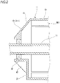
Fig. 2 is a cross-sectional view of the rotating electrical machine case ofFig. 1 accommodating the rotating electrical machine. - Hereinafter, a rotating electrical machine case according to an embodiment of the invention will be described with reference to
Figs. 1 and2 . - As illustrated in
Fig. 2 , a rotatingelectrical machine case 1 accommodates a rotating electrical machine MOT and is mounted on an electric vehicle as, for example, a front wheel drive device or a rear wheel drive device. As illustrated inFigs. 1 and2 , the rotatingelectrical machine case 1 of the embodiment includes acase body 10 having a cylindrical shape surrounding the rotating electrical machine, aside wall portion 20 provided on at least one end side of thecase body 10 in a direction (hereinafter, a rotation axis direction) in which arotation shaft 11 of the rotating electrical machine MOT extends, ashaft support portion 30 which has a cylindrical shape extending in a direction away from theside wall portion 20 along the rotation axis direction and surrounding therotation shaft 11, and a plurality ofribs 41 to 44 provided on theside wall portion 20 and extending in a radial direction when viewed from the rotation axis direction. More specifically, the plurality ofribs 41 to 44 extend radially outward from an outer peripheral surface of theshaft support portion 30 and integrally connect theshaft support portion 30 and theside wall portion 20. Hereinafter, the plurality ofribs 41 to 44, which are main parts of the invention, will be described in detail. - The plurality of
ribs 41 to 44 include first tofourth ribs 41 to 44 arranged at predetermined intervals in a circumferential direction. Circumferential widths W1, W2, W3, and W4 of the first tofourth ribs 41 to 44 are not uniform and there are at least two kinds of circumferential widths. According to such a rotatingelectrical machine case 1, by making theribs other ribs electrical machine case 1, a wide rib can be used as a pouring portion. - Specifically, the circumferential widths W1 and W2 of the
first rib 41 and thesecond rib 42 are wider than the circumferential widths W3 and W4 of thethird rib 43 and thefourth rib 44. For example, the circumferential widths W3 and W4 of thethird rib 43 and thefourth rib 44 are substantially equivalent to the circumferential widths of the ribs provided in the rotating electrical machine case (see, for example, Figs. 7 and 8 of Patent Literature 1) of the related art and the circumferential widths W1 and W2 of thefirst rib 41 and thesecond rib 42 are wider than the circumferential width of the ribs provided in the rotating electrical machine case of the related art. For example, the circumferential widths W1 and W2 are 30 mm or more. Since thethird rib 43 and thefourth rib 44 have substantially the same shape as the ribs provided in the rotating electrical machine case of the related art, detailed description thereof will be omitted. -
Information first rib 41 and thesecond rib 42 having a wide circumferential width. In the following description, when theinformation 61 and theinformation 62 are distinguished, theinformation 61 is referred to asfirst information 61 and theinformation 62 is referred to as second information. In the embodiment, thefirst rib 41 displays thefirst information 61 and thesecond rib 42 displays thesecond information 62 which is different from the first information. - The first information is information related to the rotating electrical machine MOT and, more specifically, may include at least one piece of information such as rotating electrical machine specification information indicating the specifications of the rotating electrical machine MOT, rotating electrical machine type information indicating the type of the rotating electrical machine MOT, the manufacturer of the rotating electrical machine, the manufacturing establishment, and the date of manufacture. Further, the second information may be information related to the above-described rotating electrical machine MOT and may include product information of a product equipped with the rotating electrical machine MOT or the like. However, it is preferable that the
first information 61 and thesecond information 62 are different. - According to such a rotating
electrical machine case 1, by displaying theinformation 61 and theinformation 62 related to the rotating electrical machine MOT and the like on theribs ribs case body 10 while improving the rigidity of the rotatingelectrical machine case 1. - The
first rib 41 and thesecond rib 42 haveinclined surfaces first rib 41 and thesecond rib 42 are separated from theside wall portion 20 along the rotation axis direction and are connected to theshaft support portion 30 and theinformation 61 and theinformation 62 are displayed on theinclined surfaces information 61 and theinformation 62 on theinclined surfaces ribs information 61 and theinformation 62 is improved. That is, theinformation 61 and theinformation 62 can be visually recognized from both the rotation axis direction and the radial direction. - The
information 61 and theinformation 62 can be engraved on theribs information 61 and theinformation 62 are engraved on theribs information 61 and theinformation 62 can be configured so as not to be separated from the rotatingelectrical machine case 1. - Further, the
information 61 and theinformation 62 may be sticked (adhered or welded) on theribs information 61 and theinformation 62 are sticked on theribs information 61 and theinformation 62 can be easily shown on theribs - For example, the rotating electrical machine specification information is sticked on the
first rib 41 as a label and the rotating electrical machine type information is engraved on thesecond rib 42. By doing so, by displaying different pieces ofinformation ribs information - Although various embodiments are described above with reference to the drawings, it goes without saying that the invention is not limited to such examples. It is clear that a person skilled in the art can come up with various changed examples or modification examples within the scope of the claims and it is naturally understood that the various changed examples or modification examples also belong to the technical scope of the invention. Further, each component in the above-described embodiment may be freely combined within a range that does not deviate from the gist of the invention.
- For example, the rotating electrical machine case of the above-described embodiment includes two ribs having a wide circumferential width, but the number of ribs having a wide circumferential width may be one or three or more. Further, although the rotating electrical machine case of the above-described embodiment displays information on two ribs, the number of ribs for displaying information may be one or three or more.
- Further, an information display portion may be separately provided on the outer peripheral surface or the like of the
case body 10. - At least the following matters are described in this specification. The components and the like corresponding to those of the embodiment described above are shown in parentheses, but the invention is not limited thereto.
- (1) A rotating electrical machine case (rotating electrical machine case 1) which accommodates a rotating electrical machine (rotating electrical machine MOT), the rotating electrical machine case includes,
- a case body (case body 10) having a cylindrical shape surrounding the rotating electrical machine, and
- a side wall portion (side wall portion 20) provided on at least one end side of the case body in a rotation axis direction, in which
- the side wall portion is provided with a plurality of ribs (a plurality of
ribs 41 to 44) extending in a radial direction when viewed from the rotation axis direction, and - the plurality of ribs include ribs having different circumferential widths.
- According to (1), the circumferential width (thickness) of the plurality of ribs provided in the side wall portion of the rotating electrical machine case is changed, in such a manner that, by making the rib, which requires rigidity, thicker than other ribs, it is possible to improve the rigidity and suppress the increase in weight.
- (2) The rotating electrical machine case according to (1), in which
information (first information 61) is displayed on a rib (first rib 41) of the plurality of ribs, which is wider in the circumferential width than the other ribs (third rib 43). - According to (2), by displaying the information on the rib which is at least wide in the circumferential width, the thick rib which is formed to increase rigidity can be used as an information display portion. This eliminates the need for processing to separately provide an information display portion on an outer peripheral surface or the like of the case body.
- (3) The rotating electrical machine case according to (2), further includes a shaft support portion (shaft support portion 30) having a cylindrical shape extending in a direction away from the side wall portion along the rotation axis direction, in which
- the rib (first rib 41) on which the information is displayed has an inclined surface (inclined surface 411) which extends radially inward as the rib (first rib 41) is separated from the side wall portion along the rotation axis direction and is connected to the shaft support portion, and
- the information is displayed on the inclined surface.
- According to (3), visibility is improved by displaying the information on the inclined surface provided on the rib.
- (4) The rotating electrical machine case according to (2) or (3), in which
the information is engraved on the rib. - According to (4), by engraving the information on the rib, the information can be configured so as not to be separated from the rotating electrical machine case.
- (5) The rotating electrical machine case according to (2) or (3), in which
the information is sticked on the rib. - According to (5), the information can be easily shown on the rib by sticking the information on the rib.
- (6) The rotating electrical machine case according to any one of (2) to (5), in which
- the plurality of ribs include a first rib (first rib 41) and a second rib (second rib 42) which are wider in the circumferential width than the other ribs,
- information related to the rotating electrical machine is displayed as the information on the first rib, and
- another information (second information 62) different from the information is displayed on the second rib.
- According to (6), by displaying different pieces of information on the plurality of ribs, a plurality of pieces of information can be organized and displayed.
- (7) A rotating electrical machine case (rotating electrical machine case 1) which accommodates a rotating electrical machine, the rotating electrical machine case includes,
- a case body (case body 10) having a cylindrical shape surrounding the rotating electrical machine, and
- a side wall portion (side wall portion 20) provided on at least one end side of the case body in a rotation axis direction, in which
- the side wall portion is provided with a rib (rib 41) extending in a radial direction when viewed from the rotation axis direction, and
- information (first information 61) is displayed on the rib.
- According to (7), the rib provided in the side wall portion of the rotating electrical machine case can be used as the information display portion. This eliminates the need for processing to separately provide an information display portion on the outer peripheral surface or the like of the case body.
- (8) The rotating electrical machine case according to (7), further includes a shaft support portion (shaft support portion 30) having a cylindrical shape extending in a direction away from the side wall portion along the rotation axis direction, in which
- the rib has an inclined surface (inclined surface 411) which extends radially inward as the rib is separated from the side wall portion along the rotation axis direction and is connected to the shaft support portion, and
- the information is displayed on the inclined surface.
- According to (8), visibility is improved by displaying the information on the inclined surface provided on the rib.
- (9) The rotating electrical machine case according to (7) or (8), in which
- the rib includes a first rib (first rib 41) and a second rib (second rib 42),
- information related to the rotating electrical machine is displayed as the information on the first rib, and
- another information (second information 62) different from the information is displayed on the second rib.
- According to (9), by displaying different pieces of information on the plurality of ribs, a plurality of pieces of information can be organized and displayed.
- This application is based on a Japanese patent application filed on
July 2, 2019 (Japanese Patent Application No. 2019-123959 -
- 1: rotating electrical machine case
- 10: case body
- 20: side wall portion
- 30: shaft support portion
- 41: first rib
- 411: inclined surface
- 42: second rib
- 43: third rib (other rib)
- 44: fourth rib (other rib)
- 421: inclined surface
- 61: first information (information)
- 62: second information (another information)
- MOT: rotating electrical machine
Claims (9)
- A rotating electrical machine case which accommodates a rotating electrical machine, the rotating electrical machine case comprising:a case body having a cylindrical shape surrounding the rotating electrical machine; anda side wall portion provided on at least one end side of the case body in a rotation axis direction, wherein:the side wall portion is provided with a plurality of ribs extending in a radial direction when viewed from the rotation axis direction; andthe plurality of ribs include ribs having different circumferential widths.
- The rotating electrical machine case according to claim 1, wherein
information is displayed on a rib of the plurality of ribs, which is wider in the circumferential width than the other ribs. - The rotating electrical machine case according to claim 2, further comprising:a shaft support portion having a cylindrical shape extending in a direction away from the side wall portion along the rotation axis direction, wherein:the rib on which the information is displayed has an inclined surface which extends radially inward as the rib is separated from the side wall portion along the rotation axis direction and is connected to the shaft support portion; andthe information is displayed on the inclined surface.
- The rotating electrical machine case according to claim 2 or 3, wherein
the information is engraved on the rib. - The rotating electrical machine case according to claim 2 or 3, wherein
the information is sticked on the rib. - The rotating electrical machine case according to any one of claims 2 to 5, wherein:the plurality of ribs include a first rib and a second rib which are wider in the circumferential width than the other ribs;information related to the rotating electrical machine is displayed as the information on the first rib; andanother information different from the information is displayed on the second rib.
- A rotating electrical machine case which accommodates a rotating electrical machine, the rotating electrical machine case comprising:a case body having a cylindrical shape surrounding the rotating electrical machine; anda side wall portion provided on at least one end side of the case body in a rotation axis direction, wherein:the side wall portion is provided with a rib extending in a radial direction when viewed from the rotation axis direction; andinformation is displayed on the rib.
- The rotating electrical machine case according to claim 7, further comprising:a shaft support portion having a cylindrical shape extending in a direction away from the side wall portion along the rotation axis direction, wherein:the rib has an inclined surface which extends radially inward as the rib is separated from the side wall portion along the rotation axis direction and is connected to the shaft support portion; andthe information is displayed on the inclined surface.
- The rotating electrical machine case according to claim 7 or 8, wherein:the rib includes a first rib and a second rib;information related to the rotating electrical machine is displayed as the information on the first rib; andanother information different from the information is displayed on the second rib.
Applications Claiming Priority (2)
| Application Number | Priority Date | Filing Date | Title |
|---|---|---|---|
| JP2019123959 | 2019-07-02 | ||
| PCT/JP2020/025542 WO2021002329A1 (en) | 2019-07-02 | 2020-06-29 | Rotating electrical machine case |
Publications (3)
| Publication Number | Publication Date |
|---|---|
| EP3996251A1 true EP3996251A1 (en) | 2022-05-11 |
| EP3996251A4 EP3996251A4 (en) | 2022-09-14 |
| EP3996251B1 EP3996251B1 (en) | 2024-08-21 |
Family
ID=74100128
Family Applications (1)
| Application Number | Title | Priority Date | Filing Date |
|---|---|---|---|
| EP20834387.1A Active EP3996251B1 (en) | 2019-07-02 | 2020-06-29 | Rotating electrical machine case |
Country Status (5)
| Country | Link |
|---|---|
| US (1) | US12051960B2 (en) |
| EP (1) | EP3996251B1 (en) |
| JP (1) | JP7451526B2 (en) |
| CN (1) | CN114080746B (en) |
| WO (1) | WO2021002329A1 (en) |
Family Cites Families (20)
| Publication number | Priority date | Publication date | Assignee | Title |
|---|---|---|---|---|
| JPS5899185A (en) | 1981-12-04 | 1983-06-13 | 株式会社 朝日防火板工業所 | Inorganic undercoating material |
| JPS58172356U (en) * | 1982-05-12 | 1983-11-17 | 株式会社日立製作所 | Structure of rotating machine outer frame |
| JP3709962B2 (en) * | 1998-07-09 | 2005-10-26 | 富士電機機器制御株式会社 | Rotating machine nameplate mounting device |
| US6766879B2 (en) | 2001-09-05 | 2004-07-27 | Brett Eilers | Sound reducing device for a coffee grinder and other kitchen appliances |
| JP2006518177A (en) | 2002-12-13 | 2006-08-03 | ブラック アンド デッカー インク | Stator assembly with overmolding that secures the magnet to the flux ring and the flux ring to the stator housing |
| JP4497090B2 (en) * | 2005-12-21 | 2010-07-07 | 株式会社デンソー | Vehicle alternator |
| US8502436B2 (en) * | 2011-02-14 | 2013-08-06 | Regal Beloit America, Inc. | Electric motor having an end frame |
| DE102011053611A1 (en) * | 2011-09-14 | 2013-03-14 | Ebm-Papst Mulfingen Gmbh & Co. Kg | Rotating electrical machine |
| FR2981621B1 (en) | 2011-10-20 | 2014-06-13 | Valeo Systemes Dessuyage | ASSEMBLY FOR AN ENGINE, IN PARTICULAR A MOTOR AGENCY FOR DRIVING A WIPER BLADE |
| JP6002050B2 (en) * | 2013-01-18 | 2016-10-05 | アスモ株式会社 | Brush holder device and rotating electric machine |
| CN103545966A (en) | 2013-10-23 | 2014-01-29 | 福建永强力加动力设备有限公司 | Rear end cover of electric generator |
| DE102013227056B4 (en) | 2013-12-23 | 2022-07-21 | Robert Bosch Gmbh | Housing for an electric machine with an injected bearing |
| JP6140627B2 (en) | 2014-03-11 | 2017-05-31 | 本田技研工業株式会社 | Electric motor |
| JP6506406B2 (en) | 2015-10-21 | 2019-04-24 | 三菱電機株式会社 | Outdoor unit of air conditioner and air conditioner |
| US20170366062A1 (en) | 2016-06-17 | 2017-12-21 | Nidec Corporation | Motor |
| CN206619985U (en) | 2017-02-22 | 2017-11-07 | 美明德(昆山)机械设备有限公司 | A kind of electric motor end cap |
| US11025126B2 (en) | 2017-03-20 | 2021-06-01 | Netmotor (U.S.A.) Inc. | Brushed DC motor and manufacturing method thereof |
| CN206673734U (en) | 2017-04-28 | 2017-11-24 | 上海法雷奥汽车电器系统有限公司 | A kind of generator's cover and alternating current generator |
| CN207490645U (en) * | 2017-07-31 | 2018-06-12 | 广东威灵电机制造有限公司 | The end cap and washing motor of washing motor |
| JP7108413B2 (en) | 2018-01-15 | 2022-07-28 | 東洋紡株式会社 | clothing |
-
2020
- 2020-06-29 WO PCT/JP2020/025542 patent/WO2021002329A1/en not_active Ceased
- 2020-06-29 CN CN202080047703.3A patent/CN114080746B/en active Active
- 2020-06-29 JP JP2021530019A patent/JP7451526B2/en active Active
- 2020-06-29 US US17/623,780 patent/US12051960B2/en active Active
- 2020-06-29 EP EP20834387.1A patent/EP3996251B1/en active Active
Also Published As
| Publication number | Publication date |
|---|---|
| EP3996251A4 (en) | 2022-09-14 |
| EP3996251B1 (en) | 2024-08-21 |
| CN114080746A (en) | 2022-02-22 |
| JP7451526B2 (en) | 2024-03-18 |
| CN114080746B (en) | 2024-08-30 |
| WO2021002329A1 (en) | 2021-01-07 |
| US12051960B2 (en) | 2024-07-30 |
| US20220247253A1 (en) | 2022-08-04 |
| JPWO2021002329A1 (en) | 2021-01-07 |
Similar Documents
| Publication | Publication Date | Title |
|---|---|---|
| KR100408569B1 (en) | Nonrotating Billboard of Rotation Body | |
| CN103229392B (en) | Stator | |
| US12051960B2 (en) | Rotating electrical machine case | |
| WO2018173827A1 (en) | Pump device | |
| JP2018091188A (en) | Shaft coupling cover and pump device including the same | |
| JP2003146025A (en) | tire | |
| EP3002469B1 (en) | Mounting structure for mounting component | |
| CN106979320B (en) | Gear-box shell | |
| US20120286560A1 (en) | Wheel cover for a vehicle | |
| EP2592159A2 (en) | Device for supporting molten metal container | |
| KR200466951Y1 (en) | Open/Close Type Sign Board | |
| EP2865927A1 (en) | Sealing device | |
| CN209593137U (en) | motor | |
| JP6569456B2 (en) | motor | |
| JP4735489B2 (en) | FIXED STRUCTURE AND VEHICLE INSTRUMENT HAVING THE SAME | |
| US8823224B2 (en) | Fan, electric motor, and machine tool | |
| KR200336898Y1 (en) | non-rotational emblem displayer for wheel cap | |
| US12249891B2 (en) | Motor | |
| US11368069B2 (en) | Rotary electric machine unit | |
| JP6182292B2 (en) | Blower | |
| JP5041292B2 (en) | Display device | |
| JP2002101598A (en) | Motor bracket | |
| JP2016084869A (en) | Item supporting jig | |
| JP2007278428A (en) | Bearing device | |
| JP5157824B2 (en) | Electrical junction box and method of assembling the electrical junction box |
Legal Events
| Date | Code | Title | Description |
|---|---|---|---|
| STAA | Information on the status of an ep patent application or granted ep patent |
Free format text: STATUS: THE INTERNATIONAL PUBLICATION HAS BEEN MADE |
|
| PUAI | Public reference made under article 153(3) epc to a published international application that has entered the european phase |
Free format text: ORIGINAL CODE: 0009012 |
|
| STAA | Information on the status of an ep patent application or granted ep patent |
Free format text: STATUS: REQUEST FOR EXAMINATION WAS MADE |
|
| 17P | Request for examination filed |
Effective date: 20211229 |
|
| AK | Designated contracting states |
Kind code of ref document: A1 Designated state(s): AL AT BE BG CH CY CZ DE DK EE ES FI FR GB GR HR HU IE IS IT LI LT LU LV MC MK MT NL NO PL PT RO RS SE SI SK SM TR |
|
| REG | Reference to a national code |
Ref legal event code: R079 Ipc: H02K0005060000 Ref country code: DE Ref legal event code: R079 Ref document number: 602020036375 Country of ref document: DE Free format text: PREVIOUS MAIN CLASS: H02K0005040000 Ipc: H02K0005060000 |
|
| A4 | Supplementary search report drawn up and despatched |
Effective date: 20220812 |
|
| RIC1 | Information provided on ipc code assigned before grant |
Ipc: H02K 5/16 20060101ALN20220808BHEP Ipc: H02K 5/24 20060101ALN20220808BHEP Ipc: H02K 5/15 20060101ALI20220808BHEP Ipc: H02K 5/04 20060101ALI20220808BHEP Ipc: H02K 5/06 20060101AFI20220808BHEP |
|
| DAV | Request for validation of the european patent (deleted) | ||
| DAX | Request for extension of the european patent (deleted) | ||
| STAA | Information on the status of an ep patent application or granted ep patent |
Free format text: STATUS: EXAMINATION IS IN PROGRESS |
|
| 17Q | First examination report despatched |
Effective date: 20230517 |
|
| RIC1 | Information provided on ipc code assigned before grant |
Ipc: H02K 5/16 20060101ALN20231130BHEP Ipc: H02K 5/24 20060101ALN20231130BHEP Ipc: H02K 5/15 20060101ALI20231130BHEP Ipc: H02K 5/04 20060101ALI20231130BHEP Ipc: H02K 5/06 20060101AFI20231130BHEP |
|
| RIC1 | Information provided on ipc code assigned before grant |
Ipc: H02K 5/16 20060101ALN20231215BHEP Ipc: H02K 5/24 20060101ALN20231215BHEP Ipc: H02K 5/15 20060101ALI20231215BHEP Ipc: H02K 5/04 20060101ALI20231215BHEP Ipc: H02K 5/06 20060101AFI20231215BHEP |
|
| GRAP | Despatch of communication of intention to grant a patent |
Free format text: ORIGINAL CODE: EPIDOSNIGR1 |
|
| STAA | Information on the status of an ep patent application or granted ep patent |
Free format text: STATUS: GRANT OF PATENT IS INTENDED |
|
| RIC1 | Information provided on ipc code assigned before grant |
Ipc: H02K 5/16 20060101ALN20240306BHEP Ipc: H02K 5/24 20060101ALN20240306BHEP Ipc: H02K 5/15 20060101ALI20240306BHEP Ipc: H02K 5/04 20060101ALI20240306BHEP Ipc: H02K 5/06 20060101AFI20240306BHEP |
|
| INTG | Intention to grant announced |
Effective date: 20240321 |
|
| GRAS | Grant fee paid |
Free format text: ORIGINAL CODE: EPIDOSNIGR3 |
|
| GRAA | (expected) grant |
Free format text: ORIGINAL CODE: 0009210 |
|
| STAA | Information on the status of an ep patent application or granted ep patent |
Free format text: STATUS: THE PATENT HAS BEEN GRANTED |
|
| AK | Designated contracting states |
Kind code of ref document: B1 Designated state(s): AL AT BE BG CH CY CZ DE DK EE ES FI FR GB GR HR HU IE IS IT LI LT LU LV MC MK MT NL NO PL PT RO RS SE SI SK SM TR |
|
| REG | Reference to a national code |
Ref country code: GB Ref legal event code: FG4D |
|
| REG | Reference to a national code |
Ref country code: CH Ref legal event code: EP |
|
| P01 | Opt-out of the competence of the unified patent court (upc) registered |
Free format text: CASE NUMBER: APP_43431/2024 Effective date: 20240725 |
|
| REG | Reference to a national code |
Ref country code: IE Ref legal event code: FG4D |
|
| REG | Reference to a national code |
Ref country code: DE Ref legal event code: R096 Ref document number: 602020036375 Country of ref document: DE |
|
| REG | Reference to a national code |
Ref country code: LT Ref legal event code: MG9D |
|
| REG | Reference to a national code |
Ref country code: NL Ref legal event code: MP Effective date: 20240821 |
|
| PG25 | Lapsed in a contracting state [announced via postgrant information from national office to epo] |
Ref country code: NO Free format text: LAPSE BECAUSE OF FAILURE TO SUBMIT A TRANSLATION OF THE DESCRIPTION OR TO PAY THE FEE WITHIN THE PRESCRIBED TIME-LIMIT Effective date: 20241121 |
|
| REG | Reference to a national code |
Ref country code: AT Ref legal event code: MK05 Ref document number: 1716500 Country of ref document: AT Kind code of ref document: T Effective date: 20240821 |
|
| PG25 | Lapsed in a contracting state [announced via postgrant information from national office to epo] |
Ref country code: FI Free format text: LAPSE BECAUSE OF FAILURE TO SUBMIT A TRANSLATION OF THE DESCRIPTION OR TO PAY THE FEE WITHIN THE PRESCRIBED TIME-LIMIT Effective date: 20240821 Ref country code: NL Free format text: LAPSE BECAUSE OF FAILURE TO SUBMIT A TRANSLATION OF THE DESCRIPTION OR TO PAY THE FEE WITHIN THE PRESCRIBED TIME-LIMIT Effective date: 20240821 Ref country code: PT Free format text: LAPSE BECAUSE OF FAILURE TO SUBMIT A TRANSLATION OF THE DESCRIPTION OR TO PAY THE FEE WITHIN THE PRESCRIBED TIME-LIMIT Effective date: 20241223 Ref country code: PL Free format text: LAPSE BECAUSE OF FAILURE TO SUBMIT A TRANSLATION OF THE DESCRIPTION OR TO PAY THE FEE WITHIN THE PRESCRIBED TIME-LIMIT Effective date: 20240821 Ref country code: GR Free format text: LAPSE BECAUSE OF FAILURE TO SUBMIT A TRANSLATION OF THE DESCRIPTION OR TO PAY THE FEE WITHIN THE PRESCRIBED TIME-LIMIT Effective date: 20241122 |
|
| PG25 | Lapsed in a contracting state [announced via postgrant information from national office to epo] |
Ref country code: BG Free format text: LAPSE BECAUSE OF FAILURE TO SUBMIT A TRANSLATION OF THE DESCRIPTION OR TO PAY THE FEE WITHIN THE PRESCRIBED TIME-LIMIT Effective date: 20240821 |
|
| PG25 | Lapsed in a contracting state [announced via postgrant information from national office to epo] |
Ref country code: LV Free format text: LAPSE BECAUSE OF FAILURE TO SUBMIT A TRANSLATION OF THE DESCRIPTION OR TO PAY THE FEE WITHIN THE PRESCRIBED TIME-LIMIT Effective date: 20240821 |
|
| PG25 | Lapsed in a contracting state [announced via postgrant information from national office to epo] |
Ref country code: AT Free format text: LAPSE BECAUSE OF FAILURE TO SUBMIT A TRANSLATION OF THE DESCRIPTION OR TO PAY THE FEE WITHIN THE PRESCRIBED TIME-LIMIT Effective date: 20240821 Ref country code: IS Free format text: LAPSE BECAUSE OF FAILURE TO SUBMIT A TRANSLATION OF THE DESCRIPTION OR TO PAY THE FEE WITHIN THE PRESCRIBED TIME-LIMIT Effective date: 20241221 |
|
| PG25 | Lapsed in a contracting state [announced via postgrant information from national office to epo] |
Ref country code: HR Free format text: LAPSE BECAUSE OF FAILURE TO SUBMIT A TRANSLATION OF THE DESCRIPTION OR TO PAY THE FEE WITHIN THE PRESCRIBED TIME-LIMIT Effective date: 20240821 |
|
| PG25 | Lapsed in a contracting state [announced via postgrant information from national office to epo] |
Ref country code: ES Free format text: LAPSE BECAUSE OF FAILURE TO SUBMIT A TRANSLATION OF THE DESCRIPTION OR TO PAY THE FEE WITHIN THE PRESCRIBED TIME-LIMIT Effective date: 20240821 Ref country code: RS Free format text: LAPSE BECAUSE OF FAILURE TO SUBMIT A TRANSLATION OF THE DESCRIPTION OR TO PAY THE FEE WITHIN THE PRESCRIBED TIME-LIMIT Effective date: 20241121 |
|
| PG25 | Lapsed in a contracting state [announced via postgrant information from national office to epo] |
Ref country code: RS Free format text: LAPSE BECAUSE OF FAILURE TO SUBMIT A TRANSLATION OF THE DESCRIPTION OR TO PAY THE FEE WITHIN THE PRESCRIBED TIME-LIMIT Effective date: 20241121 Ref country code: PT Free format text: LAPSE BECAUSE OF FAILURE TO SUBMIT A TRANSLATION OF THE DESCRIPTION OR TO PAY THE FEE WITHIN THE PRESCRIBED TIME-LIMIT Effective date: 20241223 Ref country code: PL Free format text: LAPSE BECAUSE OF FAILURE TO SUBMIT A TRANSLATION OF THE DESCRIPTION OR TO PAY THE FEE WITHIN THE PRESCRIBED TIME-LIMIT Effective date: 20240821 Ref country code: NO Free format text: LAPSE BECAUSE OF FAILURE TO SUBMIT A TRANSLATION OF THE DESCRIPTION OR TO PAY THE FEE WITHIN THE PRESCRIBED TIME-LIMIT Effective date: 20241121 Ref country code: NL Free format text: LAPSE BECAUSE OF FAILURE TO SUBMIT A TRANSLATION OF THE DESCRIPTION OR TO PAY THE FEE WITHIN THE PRESCRIBED TIME-LIMIT Effective date: 20240821 Ref country code: LV Free format text: LAPSE BECAUSE OF FAILURE TO SUBMIT A TRANSLATION OF THE DESCRIPTION OR TO PAY THE FEE WITHIN THE PRESCRIBED TIME-LIMIT Effective date: 20240821 Ref country code: IS Free format text: LAPSE BECAUSE OF FAILURE TO SUBMIT A TRANSLATION OF THE DESCRIPTION OR TO PAY THE FEE WITHIN THE PRESCRIBED TIME-LIMIT Effective date: 20241221 Ref country code: HR Free format text: LAPSE BECAUSE OF FAILURE TO SUBMIT A TRANSLATION OF THE DESCRIPTION OR TO PAY THE FEE WITHIN THE PRESCRIBED TIME-LIMIT Effective date: 20240821 Ref country code: GR Free format text: LAPSE BECAUSE OF FAILURE TO SUBMIT A TRANSLATION OF THE DESCRIPTION OR TO PAY THE FEE WITHIN THE PRESCRIBED TIME-LIMIT Effective date: 20241122 Ref country code: FI Free format text: LAPSE BECAUSE OF FAILURE TO SUBMIT A TRANSLATION OF THE DESCRIPTION OR TO PAY THE FEE WITHIN THE PRESCRIBED TIME-LIMIT Effective date: 20240821 Ref country code: ES Free format text: LAPSE BECAUSE OF FAILURE TO SUBMIT A TRANSLATION OF THE DESCRIPTION OR TO PAY THE FEE WITHIN THE PRESCRIBED TIME-LIMIT Effective date: 20240821 Ref country code: BG Free format text: LAPSE BECAUSE OF FAILURE TO SUBMIT A TRANSLATION OF THE DESCRIPTION OR TO PAY THE FEE WITHIN THE PRESCRIBED TIME-LIMIT Effective date: 20240821 Ref country code: AT Free format text: LAPSE BECAUSE OF FAILURE TO SUBMIT A TRANSLATION OF THE DESCRIPTION OR TO PAY THE FEE WITHIN THE PRESCRIBED TIME-LIMIT Effective date: 20240821 |
|
| PG25 | Lapsed in a contracting state [announced via postgrant information from national office to epo] |
Ref country code: SM Free format text: LAPSE BECAUSE OF FAILURE TO SUBMIT A TRANSLATION OF THE DESCRIPTION OR TO PAY THE FEE WITHIN THE PRESCRIBED TIME-LIMIT Effective date: 20240821 Ref country code: RO Free format text: LAPSE BECAUSE OF FAILURE TO SUBMIT A TRANSLATION OF THE DESCRIPTION OR TO PAY THE FEE WITHIN THE PRESCRIBED TIME-LIMIT Effective date: 20240821 Ref country code: DK Free format text: LAPSE BECAUSE OF FAILURE TO SUBMIT A TRANSLATION OF THE DESCRIPTION OR TO PAY THE FEE WITHIN THE PRESCRIBED TIME-LIMIT Effective date: 20240821 |
|
| PG25 | Lapsed in a contracting state [announced via postgrant information from national office to epo] |
Ref country code: EE Free format text: LAPSE BECAUSE OF FAILURE TO SUBMIT A TRANSLATION OF THE DESCRIPTION OR TO PAY THE FEE WITHIN THE PRESCRIBED TIME-LIMIT Effective date: 20240821 |
|
| PG25 | Lapsed in a contracting state [announced via postgrant information from national office to epo] |
Ref country code: CZ Free format text: LAPSE BECAUSE OF FAILURE TO SUBMIT A TRANSLATION OF THE DESCRIPTION OR TO PAY THE FEE WITHIN THE PRESCRIBED TIME-LIMIT Effective date: 20240821 |
|
| PG25 | Lapsed in a contracting state [announced via postgrant information from national office to epo] |
Ref country code: SK Free format text: LAPSE BECAUSE OF FAILURE TO SUBMIT A TRANSLATION OF THE DESCRIPTION OR TO PAY THE FEE WITHIN THE PRESCRIBED TIME-LIMIT Effective date: 20240821 Ref country code: IT Free format text: LAPSE BECAUSE OF FAILURE TO SUBMIT A TRANSLATION OF THE DESCRIPTION OR TO PAY THE FEE WITHIN THE PRESCRIBED TIME-LIMIT Effective date: 20240821 |
|
| REG | Reference to a national code |
Ref country code: DE Ref legal event code: R097 Ref document number: 602020036375 Country of ref document: DE |
|
| PLBE | No opposition filed within time limit |
Free format text: ORIGINAL CODE: 0009261 |
|
| STAA | Information on the status of an ep patent application or granted ep patent |
Free format text: STATUS: NO OPPOSITION FILED WITHIN TIME LIMIT |
|
| PGFP | Annual fee paid to national office [announced via postgrant information from national office to epo] |
Ref country code: DE Payment date: 20250523 Year of fee payment: 6 |
|
| RAP4 | Party data changed (patent owner data changed or rights of a patent transferred) |
Owner name: HONDA MOTOR CO., LTD. Owner name: HITACHI ASTEMO, LTD. |
|
| 26N | No opposition filed |
Effective date: 20250522 |
|
| PG25 | Lapsed in a contracting state [announced via postgrant information from national office to epo] |
Ref country code: SE Free format text: LAPSE BECAUSE OF FAILURE TO SUBMIT A TRANSLATION OF THE DESCRIPTION OR TO PAY THE FEE WITHIN THE PRESCRIBED TIME-LIMIT Effective date: 20240821 |
|
| REG | Reference to a national code |
Ref country code: CH Ref legal event code: H13 Free format text: ST27 STATUS EVENT CODE: U-0-0-H10-H13 (AS PROVIDED BY THE NATIONAL OFFICE) Effective date: 20260127 |
|
| PG25 | Lapsed in a contracting state [announced via postgrant information from national office to epo] |
Ref country code: MC Free format text: LAPSE BECAUSE OF FAILURE TO SUBMIT A TRANSLATION OF THE DESCRIPTION OR TO PAY THE FEE WITHIN THE PRESCRIBED TIME-LIMIT Effective date: 20240821 |
|
| PG25 | Lapsed in a contracting state [announced via postgrant information from national office to epo] |
Ref country code: LU Free format text: LAPSE BECAUSE OF NON-PAYMENT OF DUE FEES Effective date: 20250629 |
|
| GBPC | Gb: european patent ceased through non-payment of renewal fee |
Effective date: 20250629 |
|
| REG | Reference to a national code |
Ref country code: BE Ref legal event code: MM Effective date: 20250630 |
|
| PG25 | Lapsed in a contracting state [announced via postgrant information from national office to epo] |
Ref country code: GB Free format text: LAPSE BECAUSE OF NON-PAYMENT OF DUE FEES Effective date: 20250629 |
|
| PG25 | Lapsed in a contracting state [announced via postgrant information from national office to epo] |
Ref country code: IE Free format text: LAPSE BECAUSE OF NON-PAYMENT OF DUE FEES Effective date: 20250629 |
|
| PG25 | Lapsed in a contracting state [announced via postgrant information from national office to epo] |
Ref country code: BE Free format text: LAPSE BECAUSE OF NON-PAYMENT OF DUE FEES Effective date: 20250630 |
|
| PG25 | Lapsed in a contracting state [announced via postgrant information from national office to epo] |
Ref country code: FR Free format text: LAPSE BECAUSE OF NON-PAYMENT OF DUE FEES Effective date: 20250630 |
|
| PG25 | Lapsed in a contracting state [announced via postgrant information from national office to epo] |
Ref country code: CH Free format text: LAPSE BECAUSE OF NON-PAYMENT OF DUE FEES Effective date: 20250630 |
|
| PG25 | Lapsed in a contracting state [announced via postgrant information from national office to epo] |
Ref country code: LT Free format text: LAPSE BECAUSE OF FAILURE TO SUBMIT A TRANSLATION OF THE DESCRIPTION OR TO PAY THE FEE WITHIN THE PRESCRIBED TIME-LIMIT Effective date: 20240821 |
|
| PG25 | Lapsed in a contracting state [announced via postgrant information from national office to epo] |
Ref country code: CY Free format text: LAPSE BECAUSE OF FAILURE TO SUBMIT A TRANSLATION OF THE DESCRIPTION OR TO PAY THE FEE WITHIN THE PRESCRIBED TIME-LIMIT Effective date: 20240821 |