EP3996200A1 - Frequency control-based microwave transmission method and single-input multiple-output microwave system - Google Patents
Frequency control-based microwave transmission method and single-input multiple-output microwave system Download PDFInfo
- Publication number
- EP3996200A1 EP3996200A1 EP20873359.2A EP20873359A EP3996200A1 EP 3996200 A1 EP3996200 A1 EP 3996200A1 EP 20873359 A EP20873359 A EP 20873359A EP 3996200 A1 EP3996200 A1 EP 3996200A1
- Authority
- EP
- European Patent Office
- Prior art keywords
- input
- output
- microwave
- frequency
- input signal
- Prior art date
- Legal status (The legal status is an assumption and is not a legal conclusion. Google has not performed a legal analysis and makes no representation as to the accuracy of the status listed.)
- Pending
Links
Images

Classifications
-
- A—HUMAN NECESSITIES
- A61—MEDICAL OR VETERINARY SCIENCE; HYGIENE
- A61N—ELECTROTHERAPY; MAGNETOTHERAPY; RADIATION THERAPY; ULTRASOUND THERAPY
- A61N5/00—Radiation therapy
- A61N5/10—X-ray therapy; Gamma-ray therapy; Particle-irradiation therapy
- A61N5/1077—Beam delivery systems
- A61N5/1081—Rotating beam systems with a specific mechanical construction, e.g. gantries
-
- A—HUMAN NECESSITIES
- A61—MEDICAL OR VETERINARY SCIENCE; HYGIENE
- A61N—ELECTROTHERAPY; MAGNETOTHERAPY; RADIATION THERAPY; ULTRASOUND THERAPY
- A61N5/00—Radiation therapy
- A61N5/10—X-ray therapy; Gamma-ray therapy; Particle-irradiation therapy
- A61N5/103—Treatment planning systems
-
- H—ELECTRICITY
- H01—ELECTRIC ELEMENTS
- H01P—WAVEGUIDES; RESONATORS, LINES, OR OTHER DEVICES OF THE WAVEGUIDE TYPE
- H01P1/00—Auxiliary devices
- H01P1/20—Frequency-selective devices, e.g. filters
- H01P1/213—Frequency-selective devices, e.g. filters combining or separating two or more different frequencies
-
- A—HUMAN NECESSITIES
- A61—MEDICAL OR VETERINARY SCIENCE; HYGIENE
- A61N—ELECTROTHERAPY; MAGNETOTHERAPY; RADIATION THERAPY; ULTRASOUND THERAPY
- A61N5/00—Radiation therapy
- A61N5/10—X-ray therapy; Gamma-ray therapy; Particle-irradiation therapy
- A61N5/1042—X-ray therapy; Gamma-ray therapy; Particle-irradiation therapy with spatial modulation of the radiation beam within the treatment head
-
- A—HUMAN NECESSITIES
- A61—MEDICAL OR VETERINARY SCIENCE; HYGIENE
- A61N—ELECTROTHERAPY; MAGNETOTHERAPY; RADIATION THERAPY; ULTRASOUND THERAPY
- A61N5/00—Radiation therapy
- A61N5/10—X-ray therapy; Gamma-ray therapy; Particle-irradiation therapy
- A61N5/1048—Monitoring, verifying, controlling systems and methods
-
- A—HUMAN NECESSITIES
- A61—MEDICAL OR VETERINARY SCIENCE; HYGIENE
- A61N—ELECTROTHERAPY; MAGNETOTHERAPY; RADIATION THERAPY; ULTRASOUND THERAPY
- A61N5/00—Radiation therapy
- A61N5/10—X-ray therapy; Gamma-ray therapy; Particle-irradiation therapy
- A61N5/1077—Beam delivery systems
- A61N5/1084—Beam delivery systems for delivering multiple intersecting beams at the same time, e.g. gamma knives
-
- H—ELECTRICITY
- H01—ELECTRIC ELEMENTS
- H01P—WAVEGUIDES; RESONATORS, LINES, OR OTHER DEVICES OF THE WAVEGUIDE TYPE
- H01P1/00—Auxiliary devices
- H01P1/20—Frequency-selective devices, e.g. filters
-
- H—ELECTRICITY
- H01—ELECTRIC ELEMENTS
- H01P—WAVEGUIDES; RESONATORS, LINES, OR OTHER DEVICES OF THE WAVEGUIDE TYPE
- H01P1/00—Auxiliary devices
- H01P1/20—Frequency-selective devices, e.g. filters
- H01P1/213—Frequency-selective devices, e.g. filters combining or separating two or more different frequencies
- H01P1/2138—Frequency-selective devices, e.g. filters combining or separating two or more different frequencies using hollow waveguide filters
-
- H—ELECTRICITY
- H03—ELECTRONIC CIRCUITRY
- H03H—IMPEDANCE NETWORKS, e.g. RESONANT CIRCUITS; RESONATORS
- H03H9/00—Networks comprising electromechanical or electro-acoustic elements; Electromechanical resonators
- H03H9/0004—Impedance-matching networks
-
- H—ELECTRICITY
- H05—ELECTRIC TECHNIQUES NOT OTHERWISE PROVIDED FOR
- H05B—ELECTRIC HEATING; ELECTRIC LIGHT SOURCES NOT OTHERWISE PROVIDED FOR; CIRCUIT ARRANGEMENTS FOR ELECTRIC LIGHT SOURCES, IN GENERAL
- H05B6/00—Heating by electric, magnetic or electromagnetic fields
- H05B6/64—Heating using microwaves
- H05B6/66—Circuits
-
- H—ELECTRICITY
- H05—ELECTRIC TECHNIQUES NOT OTHERWISE PROVIDED FOR
- H05B—ELECTRIC HEATING; ELECTRIC LIGHT SOURCES NOT OTHERWISE PROVIDED FOR; CIRCUIT ARRANGEMENTS FOR ELECTRIC LIGHT SOURCES, IN GENERAL
- H05B6/00—Heating by electric, magnetic or electromagnetic fields
- H05B6/64—Heating using microwaves
- H05B6/70—Feed lines
-
- H—ELECTRICITY
- H05—ELECTRIC TECHNIQUES NOT OTHERWISE PROVIDED FOR
- H05B—ELECTRIC HEATING; ELECTRIC LIGHT SOURCES NOT OTHERWISE PROVIDED FOR; CIRCUIT ARRANGEMENTS FOR ELECTRIC LIGHT SOURCES, IN GENERAL
- H05B6/00—Heating by electric, magnetic or electromagnetic fields
- H05B6/64—Heating using microwaves
- H05B6/70—Feed lines
- H05B6/705—Feed lines using microwave tuning
-
- H—ELECTRICITY
- H05—ELECTRIC TECHNIQUES NOT OTHERWISE PROVIDED FOR
- H05B—ELECTRIC HEATING; ELECTRIC LIGHT SOURCES NOT OTHERWISE PROVIDED FOR; CIRCUIT ARRANGEMENTS FOR ELECTRIC LIGHT SOURCES, IN GENERAL
- H05B6/00—Heating by electric, magnetic or electromagnetic fields
- H05B6/64—Heating using microwaves
- H05B6/70—Feed lines
- H05B6/707—Feed lines using waveguides
-
- H—ELECTRICITY
- H05—ELECTRIC TECHNIQUES NOT OTHERWISE PROVIDED FOR
- H05B—ELECTRIC HEATING; ELECTRIC LIGHT SOURCES NOT OTHERWISE PROVIDED FOR; CIRCUIT ARRANGEMENTS FOR ELECTRIC LIGHT SOURCES, IN GENERAL
- H05B6/00—Heating by electric, magnetic or electromagnetic fields
- H05B6/64—Heating using microwaves
- H05B6/80—Apparatus for specific applications
-
- H—ELECTRICITY
- H05—ELECTRIC TECHNIQUES NOT OTHERWISE PROVIDED FOR
- H05H—PLASMA TECHNIQUE; PRODUCTION OF ACCELERATED ELECTRICALLY-CHARGED PARTICLES OR OF NEUTRONS; PRODUCTION OR ACCELERATION OF NEUTRAL MOLECULAR OR ATOMIC BEAMS
- H05H7/00—Details of devices of the types covered by groups H05H9/00, H05H11/00, H05H13/00
- H05H7/02—Circuits or systems for supplying or feeding radio-frequency energy
-
- A—HUMAN NECESSITIES
- A61—MEDICAL OR VETERINARY SCIENCE; HYGIENE
- A61N—ELECTROTHERAPY; MAGNETOTHERAPY; RADIATION THERAPY; ULTRASOUND THERAPY
- A61N5/00—Radiation therapy
- A61N5/10—X-ray therapy; Gamma-ray therapy; Particle-irradiation therapy
- A61N2005/1092—Details
-
- A—HUMAN NECESSITIES
- A61—MEDICAL OR VETERINARY SCIENCE; HYGIENE
- A61N—ELECTROTHERAPY; MAGNETOTHERAPY; RADIATION THERAPY; ULTRASOUND THERAPY
- A61N5/00—Radiation therapy
- A61N5/02—Radiation therapy using microwaves
-
- H—ELECTRICITY
- H05—ELECTRIC TECHNIQUES NOT OTHERWISE PROVIDED FOR
- H05B—ELECTRIC HEATING; ELECTRIC LIGHT SOURCES NOT OTHERWISE PROVIDED FOR; CIRCUIT ARRANGEMENTS FOR ELECTRIC LIGHT SOURCES, IN GENERAL
- H05B2206/00—Aspects relating to heating by electric, magnetic, or electromagnetic fields covered by group H05B6/00
- H05B2206/04—Heating using microwaves
- H05B2206/044—Microwave heating devices provided with two or more magnetrons or microwave sources of other kind
-
- H—ELECTRICITY
- H05—ELECTRIC TECHNIQUES NOT OTHERWISE PROVIDED FOR
- H05H—PLASMA TECHNIQUE; PRODUCTION OF ACCELERATED ELECTRICALLY-CHARGED PARTICLES OR OF NEUTRONS; PRODUCTION OR ACCELERATION OF NEUTRAL MOLECULAR OR ATOMIC BEAMS
- H05H7/00—Details of devices of the types covered by groups H05H9/00, H05H11/00, H05H13/00
- H05H7/001—Arrangements for beam delivery or irradiation
- H05H2007/002—Arrangements for beam delivery or irradiation for modifying beam trajectory, e.g. gantries
-
- H—ELECTRICITY
- H05—ELECTRIC TECHNIQUES NOT OTHERWISE PROVIDED FOR
- H05H—PLASMA TECHNIQUE; PRODUCTION OF ACCELERATED ELECTRICALLY-CHARGED PARTICLES OR OF NEUTRONS; PRODUCTION OR ACCELERATION OF NEUTRAL MOLECULAR OR ATOMIC BEAMS
- H05H7/00—Details of devices of the types covered by groups H05H9/00, H05H11/00, H05H13/00
- H05H7/02—Circuits or systems for supplying or feeding radio-frequency energy
- H05H2007/027—Microwave systems
-
- H—ELECTRICITY
- H05—ELECTRIC TECHNIQUES NOT OTHERWISE PROVIDED FOR
- H05H—PLASMA TECHNIQUE; PRODUCTION OF ACCELERATED ELECTRICALLY-CHARGED PARTICLES OR OF NEUTRONS; PRODUCTION OR ACCELERATION OF NEUTRAL MOLECULAR OR ATOMIC BEAMS
- H05H7/00—Details of devices of the types covered by groups H05H9/00, H05H11/00, H05H13/00
- H05H7/001—Arrangements for beam delivery or irradiation
Definitions
- the present disclosure relates to a field of microwave transmission technologies, and more particularly, to a microwave transmission method and a single-input multiple-output microwave system based on frequency control.
- Intensity modulated radiation therapy with a single irradiation field may achieve conformation in a two-dimensional plane in a single direction, but cannot meet conformal requirements for dose distribution in three-dimensional space.
- radiotherapy systems employ an irradiation mode with multi-angle and multi-irradiation field, which is usually achieved through mechanically rotating accelerator systems.
- a linear accelerator is mounted on a ring frame and may move in a circular motion centered on a treatment bed where a patient is during treatment to realize multi-angle irradiation.
- An outstanding disadvantage of mechanically rotating systems using a single accelerator is that time-consuming is longer, which is a common problem of a method of switching the irradiation field through mechanical movement.
- a rotating speed of the ring frame cannot be too fast.
- limitation of a movement speed of the multi-leaf optical grating that adjusts shapes of the irradiation fields also makes the mechanical movement not too fast.
- the disadvantage is acceptable for conventional irradiations with a low dose rate and a long irradiation time, but unacceptable for FLASH therapy with a high dose rate and an irradiation time less than 1 second.
- industrial CTs may also employ manners of mechanically moving accelerators. Because scanning objects of industrial CTs are larger, the corresponding frame will be larger, so the disadvantage of long time-consuming is expressed more obviously.
- a system with multiple accelerators is employed.
- a power source is one of main components of cost.
- Multiple accelerators require multiple power inputs.
- Multiple power sources are required when a traditional method of using one power source to supply one accelerator is employed, which will cause cost of the system to fold increase, and reliability problems caused by RF breakdown of the power sources to be more serious.
- Power of a single power source is required to be relatively high when the power source is used to supply multiple accelerator.
- Such high-power power sources are usually bulky and have a low repetition frequency, making it difficult to apply to rapid imaging or irradiation.
- Embodiments of the present disclosure seek to solve at least one of the problems existing in the related art to at least some extent.
- an objective of the present disclosure is to provide a microwave transmission method based on frequency control, the method may perform a selectively matching output from a corresponding output port by adjusting the frequency of the input signal.
- Another objective of the present disclosure is to provide a single-input multiple-output microwave system.
- Another objective of the present disclosure is to provide a microwave transmission apparatus based on frequency control.
- a microwave transmission method based on frequency control includes:
- a single-input multiple-output microwave system includes one input port, a 1-to-N microwave network, multiple band-pass filters and multiple output ports.
- the input port is configured to input each of the different input signals with different frequencies
- the 1-to-N microwave network comprises an input terminal and N output terminals, the input of the 1-to-N microwave network is coupled to the input port, and the output terminals of the 1-to-N microwave network are coupled to input terminals of the band-pass filters for adjustment and matching;
- the output terminals of the band-pass filters are coupled to the output ports, and are configured to pass or reflect the input signal according to the frequency of the input signal.
- a microwave transmission apparatus based on frequency control includes an input module, an assigning module and an output module.
- the input module is configured to, adjust frequency of an input signal, and each of different input signals with different frequencies is input signal of the single-input multi-output microwave system.
- the assigning module is configured to, assign the input signal to a target output port among multiple output ports of the single-input multiple-output microwave system, according to the frequency of the input signal.
- the output module is configured to, perform signal output through the target output port.
- the different input signals with different frequencies input through the input port, and the corresponding output port may be selected to output by coordinated adjustment of a 1-to-N microwave network and band-pass filters.
- different output ports are selected for output by adjusting the frequency of the input signal of the input port, and the number of output ports may be expanded according to actual requirements.
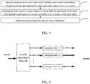
- FIG.1 is a flowchart of a microwave transmission method based on frequency control, according to an embodiment of the present disclosure.
- Step S1 frequency of an input signal is adjusted, and each of different input signals with different frequencies is input signal of the single-input multi-output microwave system.
- each of the different input signals with different frequencies may be generated within a certain frequency range by a power source.
- Step S2 the input signal is assigned to a target output port among multiple output ports of the single-input multiple-output microwave system, according to the frequency of the input signal.
- the single-input multiple-output microwave system includes one input port and multiple output ports. Any one output port only allows an input signal whose frequency is within a preset frequency range to pass, and reflects an input signal whose frequency is outside the preset frequency range. The input port is matched without reflection when the input signal whose frequency is within a preset frequency range of one output port.
- Each output port among the multiple output ports of the single-input multiple-output microwave system corresponds to one preset frequency range.
- the input signal may be output when the frequency of the input signal is within the preset frequency range, otherwise it may be reflected.
- a specific value of the preset frequency range is set according to a specific structure of the microwave system.
- Step S3 signal output is performed through the target output port.
- the signal is output.
- the frequency of the input signal is adjusted, and each of the different input signals with different frequencies is input signal of the single-input multi-output microwave system.
- the input signal is assigned to the target output port among multiple output ports of the single-input multiple-output microwave system, according to the frequency of the input signal.
- the signal output is performed through the target output port.
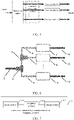
- FIG.2 is a schematic diagram of a structure of the single-input multiple-output microwave system according to an embodiment of the present disclosure.
- the single-input multiple-output microwave system includes one input port, a 1-to-N microwave network, multiple band-pass filters and multiple output ports.
- the input port is configured to input each of the different input signals with different frequencies.
- the 1-to-N microwave network includes an input terminal and N output terminals.
- the input of the 1-to-N microwave network is coupled to the input port, and the output terminals of the 1-to-N microwave network are coupled to input terminals of the band-pass filters for adjustment and matching;
- the output terminals of the band-pass filters are coupled to the output ports and are configured to pass or reflect the input signal according to the frequency of the input signal.
- the output port is configured to perform signal output.
- the single-input multiple-output microwave system only has one input port, through which each of the input signals with different frequencies may be input, and has multiple output ports, and the number of output ports may be expanded according to actual requirements.
- the 1-to-N microwave network may be essentially a multi-port network with a scattering parameter S that satisfies certain conditions.
- the 1-to-N microwave network includes an input terminal and N output terminals, and N output branches may be symmetrical. When the (N-1) output branches reflect, the remaining one output terminal of the 1-to-N microwave network matches the input terminal of the 1-to-N microwave network without reflection, and a microwave is transmitted from the input terminal of the 1-to-N microwave network to the remaining one output terminal of the 1-to-N microwave network.
- the band-pass filter is further configured to allow the input signal to entirely pass when the frequency of the input signal is within frequency passband of the band-pass filter.
- the band-pass filter is a microwave device that allows a microwave signal in a specific frequency band to pass, but reflects a microwave signal in other frequency bands.
- An ideal band-pass filter may pass an entire microwave signal whose frequency is within frequency passband, and may completely reflect an incident microwave signal whose frequencies is outside the frequency passband.
- the band-pass filter may be a resonant cavity having a passing type. When the frequency of the input signal is consistent with resonant frequency of the resonant cavity, the input signal may pass the resonant cavity entirely.
- characteristics of the pass-band filter may affect parameters of the system such as frequency, bandwidth, and loss, so the pass-band filter has a requirement to be designed and optimized.
- An appropriate bandwidth is employed in the design, not only to allow a certain frequency adjustment error, but also to ensure that passbands between band-pass filters do not overlap each other.
- the center frequencies of the band-pass filters are different, and the center frequencies are respectively f 1 , f 2 .. . f n .
- the frequency of the input signal is adjustable.
- an microwave signal may be completely transmitted in the corresponding band-pass filter and totally reflected by other band-pass filters.
- the input terminal of each band-pass filter is coupled to each of the N output terminal of the 1-to-N microwave network.
- the frequency of the input signal is consistent with the center frequency f i of the i-th band-pass filter, only the i-th branch is matched without reflection, and the others ( N-1) branches perform total reflection.
- the input terminal of the 1-to-N microwave network is also matched at this time, according to the previously designed 1-to-N microwave network function, and microwave power is completely transmitted from the input terminal of the 1-to-N microwave network to the output terminal of the branch where the i-th band-pass filter with the center frequency f i is located.
- rapid switching of different ports is achieved by controlling the frequency of the power source.
- the input port may be coupled to a power source, and the power source sends out input signals of different frequencies within a certain microwave frequency range.
- the multiple output ports are coupled to multiple device loads, and after coupling the power source, a single device load may be supplied with energy, and switching between different device loads may be performed by adjusting input frequency of the power source.
- multiple ports are coupled to multiple accelerators.
- multiple accelerators may be coupled to the output ports, and different output ports may be selected for output by adjusting the frequency of the power source to supply different accelerators. Furthermore, when different accelerators are installed at different irradiation angles, rapid switching between multi-angle irradiation fields may be realized.
- the system is faster than a solution of a mechanically rotating single accelerator, and is lower in cost than a solution with multiple power sources and multiple outputs, also has unique advantages, just like higher reliability and so on.
- FIG.4 an application scenario of the single-input multiple-output microwave system is presented.
- Multiple output ports are coupled to multiple gantries, and input signals with different frequencies are emitted out through the power source, and are output at different gantries after passing through the system.
- the gantries may be installed at different irradiation angles, which may realize rapid switching between multi-angle irradiation fields.
- frequency switching is performed between macro pulses output by the power source, and switching speed may reach order of milliseconds or even microseconds to meet requirements of FLASH radiotherapies.
- the system is faster than a solution of a mechanically rotating single accelerator, and is lower in cost than a solution with multiple power sources and multiple outputs, also has unique advantages, just like higher reliability and so on.
- the mechanism of the 1-to-N microwave network may include: at least one impedance adder, an input impedance of one port of each impedance adder is equal to the sum of impedances of the other ports of the impedance adder.
- a matched waveguide section is set between the least one impedance adder and the band-pass filters for impedance matching.
- 1 is the input port of the single-input multiple-output microwave system; 2 and 3 are impedance adders.
- FIG.6 illustrates only two impedance adders, but the number of the impedance adders may be set according to the number of the output ports in practical applications; 4, 5, and 6 are matched waveguide sections for impedance matching; 7, 8, and 9 are band-pass filters; 10, 11, and 12 are output ports. The number of the matched waveguide sections and band-pass filters is set according to actual number of the output ports. Therefore, the microwave system of the present disclosure may be discretionarily extended to multiple ports.
- the single-input multiple-output microwave system is mainly composed of the impedance adders, the band-pass filters, and the matched waveguide sections.
- the various components are described below combined with the FIG. 5 and the FIG. 6 .
- the impedance adder may be essentially a multi-port network with a scattering parameter S that satisfies certain conditions, and has a function that the input impedance of one port in the multi-port network is equal to the sum of the impedances of the remaining ports, thereby calling the impedance adder.
- the impedance adders are multiple, multiple basic three-port impedance adders are cascaded to realize the function of the microwave system.
- the resonant cavity having the passing type is taken as an example.
- An input signal having a specific resonant frequency may pass completely, and an input signal deviating from the resonant frequency may be partially or entirely reflected.
- the characteristics of the resonant cavity such as the resonant frequency, Q value (quality factor) and coupling degree may affect the frequency, bandwidth, loss and other parameters of the system, and the resonant cavity has a requirement to be designed and optimized.
- the matched waveguide sections for impedance matching are located between the impedance adder and the various band-pass filters.
- waveguide transmission lines between output terminals of the impedance adders and the input terminals of the band-pass filter are used as matched waveguide sections, length of which may be specially designed.
- the impedance of the band-pass filter when the input signal is totally reflected is not a fixed value.
- impedance of a certain output terminal of the impedance adder is short-circuited during reflection, that is, 0, so with performing the impedance matching through the matched waveguide section, the impedance of the output terminal of the impedance adder is set as a desired impedance.
- the center frequencies of the various band-pass filters are different. Taking the resonant cavity as an example, resonant frequencies of the various cavity are respectively f 1 , f 2 ... f n .
- the frequency of the microwave signal output by the power source is adjustable within a certain range.
- the frequency of the input signal is consistent with resonant frequency f i of a certain resonant cavity, the input signal may be completely transmitted in the resonant cavity and totally reflected by other resonant cavities.
- an impedance that is matched without reflection is 1, an impedance that is entirely reflected is the same as that of the short circuit, and the value is 0.
- rapid switching of different ports is achieved by controlling the frequency of the power source.
- a microwave system with a single power source supplying energy and a multi-port output is provided, and rapid switching of different ports is realized by controlling the frequency of the power source.
- the output ports are coupled to an accelerator array, the same function of multi-field irradiation as the current single-accelerator frame rotating scanning scheme may be realized, and switching speed between fields is greatly increased on this basis.
- the number of the output ports may be extended discretionarily and the frequency may be scaled discretionarily.
- FIG.7 is a block diagram of a structure of a microwave transmission apparatus based on frequency control, according to an embodiment of the present disclosure.
- the microwave transmission apparatus based on frequency control includes an input module 701, an assigning module 702 and an output module 703.
- the input module 701 is configured to, adjust frequency of an input signal, and each of different input signals with different frequencies is input signal of the single-input multi-output microwave system.
- the assigning module 702 is configured to, assign the input signal to a target output port among multiple output ports of the single-input multiple-output microwave system, according to the frequency of the input signal.
- the output module 703 is configured to, perform signal output through the target output port.
- the single-input multiple-output microwave system includes one input port and multiple output ports. Any one output port only allows the input signal whose frequency is within a preset frequency range to pass, and reflects the input signal whose frequency is outside the preset frequency range. The input port is matched without reflection when the input signal whose frequency is within a preset frequency range of one output port.
- the frequency of the input signal is adjusted, and each of the different input signals with different frequencies is input signal of the single-input multi-output microwave system.
- the input signal is assigned to the target output port among multiple output ports of the single-input multiple-output microwave system, according to the frequency of the input signal.
- the signal output is performed through the target output port.
- first and second are used herein for purposes of description and are not intended to indicate or imply relative importance or significance or to imply the number of indicated technical features.
- the feature defined with “first” and “second” may comprise one or more of this feature.
- a plurality of' means at least two, for example, two or three, unless specified otherwise.
- the terms “mounted,” “connected,” “coupled,” “fixed” and the like are used broadly, and may be, for example, fixed connections, detachable connections, or integral connections; may also be mechanical or electrical connections; may also be direct connections or indirect connections via intervening structures; may also be inner communications of two elements or interactive relationships of two elements, unless specified otherwise, which can be understood by those skilled in the art according to specific situations.
- a structure in which a first feature is "on" or “below” a second feature may include an embodiment in which the first feature is in direct contact with the second feature, and may also include an embodiment in which the first feature and the second feature are not in direct contact with each other, but are contacted via an additional feature formed therebetween.
- a first feature "on,” “above,” or “on top of' a second feature may include an embodiment in which the first feature is right or obliquely “on,” “above,” or “on top of' the second feature, or just means that the first feature is at a height higher than that of the second feature; while a first feature "below,” “under,” or “on bottom of' a second feature may include an embodiment in which the first feature is right or obliquely “below,” “under,” or “on bottom of' the second feature, or just means that the first feature is at a height lower than that of the second feature.
Landscapes
- Health & Medical Sciences (AREA)
- Engineering & Computer Science (AREA)
- Biomedical Technology (AREA)
- Physics & Mathematics (AREA)
- Electromagnetism (AREA)
- General Health & Medical Sciences (AREA)
- Public Health (AREA)
- Pathology (AREA)
- Nuclear Medicine, Radiotherapy & Molecular Imaging (AREA)
- Radiology & Medical Imaging (AREA)
- Life Sciences & Earth Sciences (AREA)
- Animal Behavior & Ethology (AREA)
- Veterinary Medicine (AREA)
- Plasma & Fusion (AREA)
- Spectroscopy & Molecular Physics (AREA)
- Acoustics & Sound (AREA)
- Particle Accelerators (AREA)
- Transmitters (AREA)
- Control Of Motors That Do Not Use Commutators (AREA)
Abstract
Description
- This application claims a priority to
Chinese Patent Application No. 202010961150.4, filed on September 14, 2020 by TSINGHUA UNIVERSITY - The present disclosure relates to a field of microwave transmission technologies, and more particularly, to a microwave transmission method and a single-input multiple-output microwave system based on frequency control.
- In recent years, rapid development of radiotherapy technologies, more particularly, technologies aimed at precise conformation, has greatly reduced side effects of the radiotherapy, expanded scope of radiotherapy indications, and put forward new requirements for medical accelerators. Intensity modulated radiation therapy with a single irradiation field may achieve conformation in a two-dimensional plane in a single direction, but cannot meet conformal requirements for dose distribution in three-dimensional space.
- At present, most radiotherapy systems employ an irradiation mode with multi-angle and multi-irradiation field, which is usually achieved through mechanically rotating accelerator systems. Exampled with a current advanced helical tomotherapy therapy system (TOMO therapy), which adopts a CT scan-like method for the radiotherapy, a linear accelerator is mounted on a ring frame and may move in a circular motion centered on a treatment bed where a patient is during treatment to realize multi-angle irradiation.
- An outstanding disadvantage of mechanically rotating systems using a single accelerator is that time-consuming is longer, which is a common problem of a method of switching the irradiation field through mechanical movement. On the one hand, for stability considerations, a rotating speed of the ring frame cannot be too fast. On the other hand, limitation of a movement speed of the multi-leaf optical grating that adjusts shapes of the irradiation fields also makes the mechanical movement not too fast. The disadvantage is acceptable for conventional irradiations with a low dose rate and a long irradiation time, but unacceptable for FLASH therapy with a high dose rate and an irradiation time less than 1 second.
- Similar to radiotherapy, industrial CTs may also employ manners of mechanically moving accelerators. Because scanning objects of industrial CTs are larger, the corresponding frame will be larger, so the disadvantage of long time-consuming is expressed more obviously.
- Therefore, in order to achieve rapid beam irradiation at multiple angles, a system with multiple accelerators is employed. In the entire accelerator system, a power source is one of main components of cost. Multiple accelerators require multiple power inputs. Multiple power sources are required when a traditional method of using one power source to supply one accelerator is employed, which will cause cost of the system to fold increase, and reliability problems caused by RF breakdown of the power sources to be more serious. Power of a single power source is required to be relatively high when the power source is used to supply multiple accelerator. Such high-power power sources are usually bulky and have a low repetition frequency, making it difficult to apply to rapid imaging or irradiation.
- Embodiments of the present disclosure seek to solve at least one of the problems existing in the related art to at least some extent.
- Accordingly, an objective of the present disclosure is to provide a microwave transmission method based on frequency control, the method may perform a selectively matching output from a corresponding output port by adjusting the frequency of the input signal.
- Another objective of the present disclosure is to provide a single-input multiple-output microwave system.
- Another objective of the present disclosure is to provide a microwave transmission apparatus based on frequency control.
- To achieve the above objectives, according to an aspect of the present disclosure, a microwave transmission method based on frequency control is provided. The method includes:
- adjusting frequency of an input signal, each of different input signals with different frequencies being input signal of the single-input multi-output microwave system;
- assigning the input signal to a target output port among multiple output ports of the single-input multiple-output microwave system, according to the frequency of the input signal; and
- performing signal output through the target output port.
- To achieve the above objectives, according to another aspect of the present disclosure, a single-input multiple-output microwave system is provided. The system includes one input port, a 1-to-N microwave network, multiple band-pass filters and multiple output ports.
- The input port is configured to input each of the different input signals with different frequencies;
- The 1-to-N microwave network comprises an input terminal and N output terminals, the input of the 1-to-N microwave network is coupled to the input port, and the output terminals of the 1-to-N microwave network are coupled to input terminals of the band-pass filters for adjustment and matching;
- The output terminals of the band-pass filters are coupled to the output ports, and are configured to pass or reflect the input signal according to the frequency of the input signal.
- To achieve the above objectives, according to another aspect of the present disclosure, a microwave transmission apparatus based on frequency control is provided. The apparatus includes an input module, an assigning module and an output module.
- The input module is configured to, adjust frequency of an input signal, and each of different input signals with different frequencies is input signal of the single-input multi-output microwave system.
- The assigning module is configured to, assign the input signal to a target output port among multiple output ports of the single-input multiple-output microwave system, according to the frequency of the input signal.
- The output module is configured to, perform signal output through the target output port.
- With the microwave transmission method and the apparatus based on frequency control and the single-input multiple-output microwave system in embodiments of the present disclosure, the different input signals with different frequencies input through the input port, and the corresponding output port may be selected to output by coordinated adjustment of a 1-to-N microwave network and band-pass filters. Thus, different output ports are selected for output by adjusting the frequency of the input signal of the input port, and the number of output ports may be expanded according to actual requirements.
- Additional aspects and advantages of embodiments of present disclosure will be given in part in the following descriptions, become apparent in part from the following descriptions, or be learned from the practice of the embodiments of the present disclosure.
- These and other aspects and advantages of embodiments of the present disclosure will become apparent and more readily appreciated from the following descriptions made with reference to the drawings, in which:
-
FIG.1 is a flowchart of a microwave transmission method based on frequency control according to an embodiment of the present disclosure. -
FIG.2 is a block diagram of a structure of a single-input multi-output microwave system according to an embodiment of the present disclosure. -
FIG.3 is a block diagram of a structure of a single-input multi-output microwave system according to another embodiment of the present disclosure. -
FIG.4 is a block diagram of a structure of a single-input multi-output microwave system according to another embodiment of the present disclosure. -
FIG.5 is a block diagram of a structure of a single-input multi-output microwave system according to another embodiment of the present disclosure. -
FIG.6 is a block diagram of a specific structure of a single-input multi-output microwave system according to an embodiment of the present disclosure. -
FIG.7 is a block diagram of a structure of a microwave transmission apparatus based on frequency control according to an embodiment of the present disclosure. - Reference will be made in detail to embodiments of the present disclosure. Examples of the embodiments of the present disclosure will be shown in drawings, in which the same or similar elements and the elements having same or similar functions are denoted by like reference numerals throughout the descriptions. The embodiments described herein according to drawings are explanatory and illustrative, not construed to limit the present disclosure.
- A microwave transmission method, an apparatus and a single-input multiple-output microwave system based on frequency control according to the embodiments of the present disclosure are described with reference to the accompany drawings.
-
FIG.1 is a flowchart of a microwave transmission method based on frequency control, according to an embodiment of the present disclosure. - Step S1, frequency of an input signal is adjusted, and each of different input signals with different frequencies is input signal of the single-input multi-output microwave system.
- Specifically, each of the different input signals with different frequencies may be generated within a certain frequency range by a power source.
- Step S2, the input signal is assigned to a target output port among multiple output ports of the single-input multiple-output microwave system, according to the frequency of the input signal.
- Further, the single-input multiple-output microwave system includes one input port and multiple output ports. Any one output port only allows an input signal whose frequency is within a preset frequency range to pass, and reflects an input signal whose frequency is outside the preset frequency range. The input port is matched without reflection when the input signal whose frequency is within a preset frequency range of one output port.
- It is appreciated that an input signal of a certain frequency is input. Each output port among the multiple output ports of the single-input multiple-output microwave system corresponds to one preset frequency range. The input signal may be output when the frequency of the input signal is within the preset frequency range, otherwise it may be reflected. A specific value of the preset frequency range is set according to a specific structure of the microwave system.
- Step S3, signal output is performed through the target output port.
- Specifically, after the target output port is selected, the signal is output.
- With the microwave transmission method based on frequency control proposed in the embodiments of the present disclosure, the frequency of the input signal is adjusted, and each of the different input signals with different frequencies is input signal of the single-input multi-output microwave system. The input signal is assigned to the target output port among multiple output ports of the single-input multiple-output microwave system, according to the frequency of the input signal. The signal output is performed through the target output port. Thus, a function of performing a selectively matching output from the corresponding output port when adjusting the frequency of the input signal is realized.
- The following describes the single-input multiple-output microwave system in the embodiments of the present disclosure.
-
FIG.2 is a schematic diagram of a structure of the single-input multiple-output microwave system according to an embodiment of the present disclosure. - As illustrated in
FIG.2 , the single-input multiple-output microwave system includes one input port, a 1-to-N microwave network, multiple band-pass filters and multiple output ports. - The input port is configured to input each of the different input signals with different frequencies.
- The 1-to-N microwave network includes an input terminal and N output terminals. The input of the 1-to-N microwave network is coupled to the input port, and the output terminals of the 1-to-N microwave network are coupled to input terminals of the band-pass filters for adjustment and matching;
- The output terminals of the band-pass filters are coupled to the output ports and are configured to pass or reflect the input signal according to the frequency of the input signal.
- The output port is configured to perform signal output.
- The single-input multiple-output microwave system (SIMO) only has one input port, through which each of the input signals with different frequencies may be input, and has multiple output ports, and the number of output ports may be expanded according to actual requirements.
- Further, in embodiments of the present disclosure, the 1-to-N microwave network may be essentially a multi-port network with a scattering parameter S that satisfies certain conditions. The 1-to-N microwave network includes an input terminal and N output terminals, and N output branches may be symmetrical. When the (N-1) output branches reflect, the remaining one output terminal of the 1-to-N microwave network matches the input terminal of the 1-to-N microwave network without reflection, and a microwave is transmitted from the input terminal of the 1-to-N microwave network to the remaining one output terminal of the 1-to-N microwave network. For the 1-to-N microwave network, the ideal S matrix may be expressed as:

- Further, the band-pass filter is further configured to allow the input signal to entirely pass when the frequency of the input signal is within frequency passband of the band-pass filter.
- Specifically, the band-pass filter is a microwave device that allows a microwave signal in a specific frequency band to pass, but reflects a microwave signal in other frequency bands. An ideal band-pass filter may pass an entire microwave signal whose frequency is within frequency passband, and may completely reflect an incident microwave signal whose frequencies is outside the frequency passband. As a specific implementation manner, the band-pass filter may be a resonant cavity having a passing type. When the frequency of the input signal is consistent with resonant frequency of the resonant cavity, the input signal may pass the resonant cavity entirely.
- In actual application scenarios, characteristics of the pass-band filter, such as center frequency, passband width, and transmission efficiency, may affect parameters of the system such as frequency, bandwidth, and loss, so the pass-band filter has a requirement to be designed and optimized. An appropriate bandwidth is employed in the design, not only to allow a certain frequency adjustment error, but also to ensure that passbands between band-pass filters do not overlap each other.
- Further, the center frequencies of the band-pass filters are different, and the center frequencies are respectively f 1, f 2 ... fn . The frequency of the input signal is adjustable. When the frequency of the input signal is consistent with center frequency fi of a certain resonant cavity, an microwave signal may be completely transmitted in the corresponding band-pass filter and totally reflected by other band-pass filters. The input terminal of each band-pass filter is coupled to each of the N output terminal of the 1-to-N microwave network. When the frequency of the input signal is consistent with the center frequency fi of the i-th band-pass filter, only the i-th branch is matched without reflection, and the others ( N-1) branches perform total reflection. the input terminal of the 1-to-N microwave network is also matched at this time, according to the previously designed 1-to-N microwave network function, and microwave power is completely transmitted from the input terminal of the 1-to-N microwave network to the output terminal of the branch where the i-th band-pass filter with the center frequency fi is located. Thus, rapid switching of different ports is achieved by controlling the frequency of the power source.
- As illustrated in
FIG.3 , an application scenario of the single-input multiple-output microwave system is presented. Specifically, the input port may be coupled to a power source, and the power source sends out input signals of different frequencies within a certain microwave frequency range. - Furthermore, the multiple output ports are coupled to multiple device loads, and after coupling the power source, a single device load may be supplied with energy, and switching between different device loads may be performed by adjusting input frequency of the power source. For example, multiple ports are coupled to multiple accelerators.
- In embodiments of the present disclosure, multiple accelerators may be coupled to the output ports, and different output ports may be selected for output by adjusting the frequency of the power source to supply different accelerators. Furthermore, when different accelerators are installed at different irradiation angles, rapid switching between multi-angle irradiation fields may be realized. The system is faster than a solution of a mechanically rotating single accelerator, and is lower in cost than a solution with multiple power sources and multiple outputs, also has unique advantages, just like higher reliability and so on.
- As illustrated in
FIG.4 , an application scenario of the single-input multiple-output microwave system is presented. Multiple output ports are coupled to multiple gantries, and input signals with different frequencies are emitted out through the power source, and are output at different gantries after passing through the system. The gantries may be installed at different irradiation angles, which may realize rapid switching between multi-angle irradiation fields. To ensure stability of the system, frequency switching is performed between macro pulses output by the power source, and switching speed may reach order of milliseconds or even microseconds to meet requirements of FLASH radiotherapies. The system is faster than a solution of a mechanically rotating single accelerator, and is lower in cost than a solution with multiple power sources and multiple outputs, also has unique advantages, just like higher reliability and so on. - As illustrated in
FIG.5 , a specific structure of the single-input multiple-output microwave system according to an embodiment of the present disclosure is presented. The mechanism of the 1-to-N microwave network may include: at least one impedance adder, an input impedance of one port of each impedance adder is equal to the sum of impedances of the other ports of the impedance adder. A matched waveguide section is set between the least one impedance adder and the band-pass filters for impedance matching. - Combined with
FIG.5 and FIG.6 , in theFIG.6 ,1 is the input port of the single-input multiple-output microwave system; 2 and 3 are impedance adders.FIG.6 illustrates only two impedance adders, but the number of the impedance adders may be set according to the number of the output ports in practical applications; 4, 5, and 6 are matched waveguide sections for impedance matching; 7, 8, and 9 are band-pass filters; 10, 11, and 12 are output ports. The number of the matched waveguide sections and band-pass filters is set according to actual number of the output ports. Therefore, the microwave system of the present disclosure may be discretionarily extended to multiple ports. - The single-input multiple-output microwave system is mainly composed of the impedance adders, the band-pass filters, and the matched waveguide sections. The various components are described below combined with the
FIG. 5 and theFIG. 6 . - In detail, the impedance adder may be essentially a multi-port network with a scattering parameter S that satisfies certain conditions, and has a function that the input impedance of one port in the multi-port network is equal to the sum of the impedances of the remaining ports, thereby calling the impedance adder. When the impedance adders are multiple, multiple basic three-port impedance adders are cascaded to realize the function of the microwave system.
- Many devices may be used as the band-pass filters. In a specific embodiment of the present disclosure, the resonant cavity having the passing type is taken as an example. An input signal having a specific resonant frequency may pass completely, and an input signal deviating from the resonant frequency may be partially or entirely reflected. The characteristics of the resonant cavity such as the resonant frequency, Q value (quality factor) and coupling degree may affect the frequency, bandwidth, loss and other parameters of the system, and the resonant cavity has a requirement to be designed and optimized.
- Specifically, the matched waveguide sections for impedance matching are located between the impedance adder and the various band-pass filters. Combine with
FIG.6 , waveguide transmission lines between output terminals of the impedance adders and the input terminals of the band-pass filter are used as matched waveguide sections, length of which may be specially designed. The impedance of the band-pass filter when the input signal is totally reflected is not a fixed value. In order to output the input signal at a specific output port, impedance of a certain output terminal of the impedance adder is short-circuited during reflection, that is, 0, so with performing the impedance matching through the matched waveguide section, the impedance of the output terminal of the impedance adder is set as a desired impedance. - Further, the center frequencies of the various band-pass filters are different. Taking the resonant cavity as an example, resonant frequencies of the various cavity are respectively f 1, f 2 ... fn . The frequency of the microwave signal output by the power source is adjustable within a certain range. When the frequency of the input signal is consistent with resonant frequency fi of a certain resonant cavity, the input signal may be completely transmitted in the resonant cavity and totally reflected by other resonant cavities. Through the matched waveguide sections, an impedance that is matched without reflection is 1, an impedance that is entirely reflected is the same as that of the short circuit, and the value is 0. Due to the function of the impedance adder, the impedance of the input terminal is the sum of the impedances of all ports, and the value is 1+(n-1)∗0=1, which means that the input port is matched, and the power is entirely transmitted to the branch where the resonant cavity with the resonant frequency fi is located. Thus, rapid switching of different ports is achieved by controlling the frequency of the power source.
- With the single-input multiple-output microwave system proposed in embodiments of the present disclosure, a microwave system with a single power source supplying energy and a multi-port output is provided, and rapid switching of different ports is realized by controlling the frequency of the power source. When the output ports are coupled to an accelerator array, the same function of multi-field irradiation as the current single-accelerator frame rotating scanning scheme may be realized, and switching speed between fields is greatly increased on this basis. The number of the output ports may be extended discretionarily and the frequency may be scaled discretionarily.
-
FIG.7 is a block diagram of a structure of a microwave transmission apparatus based on frequency control, according to an embodiment of the present disclosure. - As illustrated in
FIG.7 , the microwave transmission apparatus based on frequency control includes aninput module 701, an assigningmodule 702 and anoutput module 703. - The
input module 701 is configured to, adjust frequency of an input signal, and each of different input signals with different frequencies is input signal of the single-input multi-output microwave system. - The assigning
module 702 is configured to, assign the input signal to a target output port among multiple output ports of the single-input multiple-output microwave system, according to the frequency of the input signal. - The
output module 703 is configured to, perform signal output through the target output port. - Further, in an embodiment of the present disclosure, the single-input multiple-output microwave system includes one input port and multiple output ports. Any one output port only allows the input signal whose frequency is within a preset frequency range to pass, and reflects the input signal whose frequency is outside the preset frequency range. The input port is matched without reflection when the input signal whose frequency is within a preset frequency range of one output port.
- With the microwave transmission apparatus based on frequency control proposed in the embodiments of the present disclosure, the frequency of the input signal is adjusted, and each of the different input signals with different frequencies is input signal of the single-input multi-output microwave system. The input signal is assigned to the target output port among multiple output ports of the single-input multiple-output microwave system, according to the frequency of the input signal. The signal output is performed through the target output port. Thus, a function of performing a selectively matching output from the corresponding output port when adjusting the frequency of the input signal is realized.
- In the specification, it is to be understood that terms such as "central," "longitudinal," "lateral," "length," "width," "thickness," "upper," "lower," "front," "rear," "left," "right," "vertical," "horizontal," "top," "bottom," "inner," "outer," "clockwise,", "counterclockwise", "axial", "radial" and "circumferential" should be construed to refer to the orientation as then described or as shown in the drawings under discussion for simplifying the description of the present disclosure, but do not alone indicate or imply that the device or element referred to must have a particular orientation. Moreover, it is not required that the present disclosure is constructed or operated in a particular orientation. Therefore, it cannot be construed as limitation of the present disclosure.
- In addition, terms such as "first" and "second" are used herein for purposes of description and are not intended to indicate or imply relative importance or significance or to imply the number of indicated technical features. Thus, the feature defined with "first" and "second" may comprise one or more of this feature. In the description of the present invention, "a plurality of' means at least two, for example, two or three, unless specified otherwise.
- In the present invention, unless specified or limited otherwise, the terms "mounted," "connected," "coupled," "fixed" and the like are used broadly, and may be, for example, fixed connections, detachable connections, or integral connections; may also be mechanical or electrical connections; may also be direct connections or indirect connections via intervening structures; may also be inner communications of two elements or interactive relationships of two elements, unless specified otherwise, which can be understood by those skilled in the art according to specific situations.
- In the present invention, unless specified or limited otherwise, a structure in which a first feature is "on" or "below" a second feature may include an embodiment in which the first feature is in direct contact with the second feature, and may also include an embodiment in which the first feature and the second feature are not in direct contact with each other, but are contacted via an additional feature formed therebetween. Furthermore, a first feature "on," "above," or "on top of' a second feature may include an embodiment in which the first feature is right or obliquely "on," "above," or "on top of' the second feature, or just means that the first feature is at a height higher than that of the second feature; while a first feature "below," "under," or "on bottom of' a second feature may include an embodiment in which the first feature is right or obliquely "below," "under," or "on bottom of' the second feature, or just means that the first feature is at a height lower than that of the second feature.
- Reference throughout this specification to "an embodiment," "some embodiments," "an example," "a specific example," or "some examples," means that a particular feature, structure, material, or characteristic described in connection with the embodiment or example is included in at least one embodiment or example of the present disclosure. Thus, schematic representations of the above terms are not necessarily referring to the same embodiment or example. Furthermore, the particular features, structures, materials, or characteristics may be combined in any suitable manner in one or more embodiments or examples. In addition, without contradiction, different embodiments or examples and the features of the different embodiments or examples described in this specification can be combined and assorted by those skilled in the art.
- Although explanatory embodiments have been shown and described, it would be appreciated by those skilled in the art that the above embodiments are exemplary and cannot be construed to limit the present disclosure, and changes, revisions, alternatives, and modifications can be made in the embodiments within scope of the present disclosure.
Claims (11)
- A microwave transmission method based on frequency control, comprising:adjusting frequency of an input signal, each of different input signals with different frequencies being input signal of the single-input multi-output microwave system;assigning the input signal to a target output port among multiple output ports of the single-input multiple-output microwave system, according to the frequency of the input signal; andperforming signal output through the target output port.
- The method according to claim 1, wherein the single-input multiple-output microwave system comprises one input port and multiple output ports, one output port allows an input signal whose frequency is within a preset frequency range to pass, and reflects an input signal whose frequency is outside the preset frequency range, the input port is matched without reflection when the input signal whose frequency is within a preset frequency range of one output port.
- A single-input multiple-output microwave system, comprising one input port, a 1-to-N microwave network, multiple band-pass filters and multiple output ports, wherein,the input port is configured to input each of the different input signals with different frequencies;the 1-to-N microwave network comprises an input terminal and N output terminals, the input of the 1-to-N microwave network is coupled to the input port, and the output terminals of the 1-to-N microwave network are coupled to input terminals of the band-pass filters for adjustment and matching;the output terminals of the band-pass filters are coupled to the output ports, and are configured to pass or reflect the input signal according to the frequency of the input signal.
- The single-input multiple-output microwave system according to claim 3, wherein, when the (N-1) output branches reflect, the remaining one output terminal of the 1-to-N microwave network matches the input terminal of the 1-to-N microwave network without reflection, and a microwave is transmitted from the input terminal of the 1-to-N microwave network to the remaining one output terminal of the 1-to-N microwave network.
- The single-input multiple-output microwave system according to claim 3 or 4, wherein, the 1-to-N microwave network comprises at least one impedance adder, an input impedance of one port of each impedance adder is equal to the sum of impedances of the other ports of the impedance adder;multiple basic three-port impedance adders are cascaded when the impedance adders are multiple;matched waveguide sections for impedance matching are located between the impedance adder and the various band-pass filters;the microwave network is formed by the matched waveguide sections are located between the impedance adder and the various band-pass filters, and a scattering parameter matrix S of the microwave network is:

- The single-input multiple-output microwave system according to claim 3, wherein, the input port is coupled to a power source, and the power source generate each of the different input signals with different frequencies within a certain microwave frequency range.
- The single-input multiple-output microwave system according to claim 3, wherein, the multiple output ports are coupled to multiple device loads, power is supplied to a particular device load by changing the frequency of the input signal.
- The single-input multiple-output microwave system according to claim 3 or 7, wherein, the multiple output ports are coupled to multiple accelerators, the multiple accelerators are installed at different irradiation angles, switching between multi-angle irradiation fields is performed according to each of the input signals with different frequencies.
- The single-input multiple-output microwave system according to claim 3, wherein, the band-pass filter is further configured to allow the input signal to entirely pass when the frequency of the input signal is within frequency passband of the band-pass.
- The single-input multiple-output microwave system according to claim 3 or 9, wherein, the band-pass filter is a resonant cavity having a passing type, and the input signal entirely passes the resonant cavity when the frequency of the input signal is consistent with resonant frequency of the resonant cavity.
- A microwave transmission apparatus based on frequency control, comprising:an input module, configured to, adjust frequency of an input signal, and each of different input signals with different frequencies is input signal of the single-input multi-output microwave system.an assigning module, configured to, assign the input signal to a target output port among multiple output ports of the single-input multiple-output microwave system, according to the frequency of the input signal.an output module, configured to, perform signal output through the target output port.
Applications Claiming Priority (2)
| Application Number | Priority Date | Filing Date | Title |
|---|---|---|---|
| CN202010961150.4A CN112259943B (en) | 2020-09-14 | 2020-09-14 | Microwave transmission method based on frequency control and single-input multiple-output microwave system |
| PCT/CN2020/120462 WO2022052200A1 (en) | 2020-09-14 | 2020-10-12 | Frequency control-based microwave transmission method and single-input multiple-output microwave system |
Publications (2)
| Publication Number | Publication Date |
|---|---|
| EP3996200A1 true EP3996200A1 (en) | 2022-05-11 |
| EP3996200A4 EP3996200A4 (en) | 2022-09-07 |
Family
ID=80627450
Family Applications (1)
| Application Number | Title | Priority Date | Filing Date |
|---|---|---|---|
| EP20873359.2A Pending EP3996200A4 (en) | 2020-09-14 | 2020-10-12 | FREQUENCY CONTROL BASED MICROWAVE TRANSMISSION METHOD AND SINGLE INPUT MULTIPLE OUTPUT MICROWAVE SYSTEM |
Country Status (2)
| Country | Link |
|---|---|
| US (1) | US12191551B2 (en) |
| EP (1) | EP3996200A4 (en) |
Families Citing this family (3)
| Publication number | Priority date | Publication date | Assignee | Title |
|---|---|---|---|---|
| US12337194B2 (en) * | 2021-08-17 | 2025-06-24 | Varian Medical Systems, Inc. | Movable/replaceable high intensity target and multiple accelerator systems and methods |
| WO2023178611A1 (en) * | 2022-03-24 | 2023-09-28 | 清华大学 | Microwave power distribution network and method based on phase-frequency hybrid control |
| CN115544861B (en) * | 2022-09-08 | 2026-01-02 | 电子科技大学长三角研究院(湖州) | A method for designing a reflection-free structure for perfect transmission through complex media |
Family Cites Families (5)
| Publication number | Priority date | Publication date | Assignee | Title |
|---|---|---|---|---|
| US5748057A (en) * | 1996-06-03 | 1998-05-05 | Hughes Electronics | Photonic bandgap crystal frequency multiplexers and a pulse blanking filter for use therewith |
| ES2369538T3 (en) * | 2004-11-26 | 2011-12-01 | Thales | GENERAL MULTIPLEXATION NETWORK. |
| US7936858B2 (en) | 2007-09-28 | 2011-05-03 | Siemens Medical Solutions Usa, Inc. | System and method for tomosynthesis |
| EP2337145A1 (en) * | 2009-12-18 | 2011-06-22 | Thales | Compact and adjustable power divider and filter device |
| US10164724B2 (en) * | 2016-09-26 | 2018-12-25 | International Business Machines Corporation | Microwave combiner and distributer for quantum signals using frequency-division multiplexing |
-
2020
- 2020-10-12 EP EP20873359.2A patent/EP3996200A4/en active Pending
- 2020-10-12 US US17/287,470 patent/US12191551B2/en active Active
Also Published As
| Publication number | Publication date |
|---|---|
| EP3996200A4 (en) | 2022-09-07 |
| US12191551B2 (en) | 2025-01-07 |
| US20220086966A1 (en) | 2022-03-17 |
Similar Documents
| Publication | Publication Date | Title |
|---|---|---|
| US12191551B2 (en) | Single-input to N-output microwave system including multiple band-pass filters and multiple accelerators configured for selective irradiation at different angles | |
| JP3730259B2 (en) | Microwave power control for linear accelerators | |
| EP2033263B1 (en) | Antenna array calibration | |
| CN112259943B (en) | Microwave transmission method based on frequency control and single-input multiple-output microwave system | |
| US20160056982A1 (en) | Phase Control Method, Array Antenna, and System | |
| KR100257414B1 (en) | Combined Line Cavity Resonator Filter Structure and Microwave Interdigital Filter Structure | |
| CN110768021B (en) | Lens structure, lens antenna and electronic equipment | |
| CN110739552B (en) | Lens structure, lens antenna and electronic equipment | |
| CN212967976U (en) | Single-input and multiple-output microwave system based on frequency control | |
| CN115134985A (en) | High-power microwave switch and X-ray source for FLASH radiotherapy | |
| KR102950955B1 (en) | Differential time delay shifter device and method | |
| CN110768022B (en) | Lens structure, lens antenna and electronic equipment | |
| CN110752446B (en) | Lens structure, lens antenna and electronic equipment | |
| KR101172185B1 (en) | N-port feeding system having a structure in which patterns are divided with in parallel and feeding element included in the same | |
| EP4136704A1 (en) | Advanced antenna system (aas) subarray splitter with advanced upper sidelobe suppression (auss) | |
| CN114899566A (en) | Waveform transformation attenuation device and millimeter wave therapeutic instrument | |
| EP4498510B1 (en) | Microwave power distribution network and method based on phase-frequency hybrid control | |
| KR101656372B1 (en) | Compact multi harmonic buncher | |
| EP4160820A1 (en) | Radio communication system | |
| CN111952736A (en) | A scalable and controllable plasma excitation power source | |
| CN112751207B (en) | Lens structure, lens antenna and electronic equipment | |
| CN222706682U (en) | Energy-adjustable electron linear acceleration structure | |
| EP4642170A1 (en) | Radiofrequency apparatus for a radiotherapy system | |
| CN111969337B (en) | Control method of extensible controllable plasma excitation power source | |
| CN112751206B (en) | Lens structure, lens antenna and electronic equipment |
Legal Events
| Date | Code | Title | Description |
|---|---|---|---|
| STAA | Information on the status of an ep patent application or granted ep patent |
Free format text: STATUS: UNKNOWN |
|
| STAA | Information on the status of an ep patent application or granted ep patent |
Free format text: STATUS: THE INTERNATIONAL PUBLICATION HAS BEEN MADE |
|
| PUAI | Public reference made under article 153(3) epc to a published international application that has entered the european phase |
Free format text: ORIGINAL CODE: 0009012 |
|
| STAA | Information on the status of an ep patent application or granted ep patent |
Free format text: STATUS: REQUEST FOR EXAMINATION WAS MADE |
|
| 17P | Request for examination filed |
Effective date: 20210415 |
|
| AK | Designated contracting states |
Kind code of ref document: A1 Designated state(s): AL AT BE BG CH CY CZ DE DK EE ES FI FR GB GR HR HU IE IS IT LI LT LU LV MC MK MT NL NO PL PT RO RS SE SI SK SM TR |
|
| REG | Reference to a national code |
Ref country code: DE Ref legal event code: R079 Free format text: PREVIOUS MAIN CLASS: H01P0001213000 Ipc: A61N0005100000 |
|
| A4 | Supplementary search report drawn up and despatched |
Effective date: 20220810 |
|
| RIC1 | Information provided on ipc code assigned before grant |
Ipc: H05B 6/80 20060101ALI20220804BHEP Ipc: H05B 6/70 20060101ALI20220804BHEP Ipc: H01P 1/213 20060101ALI20220804BHEP Ipc: A61N 5/10 20060101AFI20220804BHEP Ipc: H05H 7/00 20060101ALN20220804BHEP Ipc: H05H 7/02 20060101ALI20220804BHEP |
|
| DAV | Request for validation of the european patent (deleted) | ||
| DAX | Request for extension of the european patent (deleted) | ||
| STAA | Information on the status of an ep patent application or granted ep patent |
Free format text: STATUS: EXAMINATION IS IN PROGRESS |
|
| 17Q | First examination report despatched |
Effective date: 20241022 |
|
| RIC1 | Information provided on ipc code assigned before grant |
Ipc: A61N 5/10 20060101AFI20260128BHEP Ipc: H01P 1/213 20060101ALI20260128BHEP Ipc: H05B 6/70 20060101ALI20260128BHEP Ipc: H05B 6/80 20060101ALI20260128BHEP Ipc: H05H 7/02 20060101ALI20260128BHEP Ipc: H05H 7/00 20060101ALN20260128BHEP |
|
| GRAP | Despatch of communication of intention to grant a patent |
Free format text: ORIGINAL CODE: EPIDOSNIGR1 |
|
| STAA | Information on the status of an ep patent application or granted ep patent |
Free format text: STATUS: GRANT OF PATENT IS INTENDED |
|
| INTG | Intention to grant announced |
Effective date: 20260309 |
|
| RIC1 | Information provided on ipc code assigned before grant |
Ipc: A61N 5/10 20060101AFI20260302BHEP Ipc: H01P 1/213 20060101ALI20260302BHEP Ipc: H05B 6/70 20060101ALI20260302BHEP Ipc: H05B 6/80 20060101ALI20260302BHEP Ipc: H05H 7/02 20060101ALI20260302BHEP Ipc: H05H 7/00 20060101ALN20260302BHEP |