EP3996189A1 - Battery pack - Google Patents
Battery pack Download PDFInfo
- Publication number
- EP3996189A1 EP3996189A1 EP20853298.6A EP20853298A EP3996189A1 EP 3996189 A1 EP3996189 A1 EP 3996189A1 EP 20853298 A EP20853298 A EP 20853298A EP 3996189 A1 EP3996189 A1 EP 3996189A1
- Authority
- EP
- European Patent Office
- Prior art keywords
- battery
- batteries
- tab
- battery pack
- multiple batteries
- Prior art date
- Legal status (The legal status is an assumption and is not a legal conclusion. Google has not performed a legal analysis and makes no representation as to the accuracy of the status listed.)
- Pending
Links
Images





Classifications
-
- H—ELECTRICITY
- H01—ELECTRIC ELEMENTS
- H01M—PROCESSES OR MEANS, e.g. BATTERIES, FOR THE DIRECT CONVERSION OF CHEMICAL ENERGY INTO ELECTRICAL ENERGY
- H01M50/00—Constructional details or processes of manufacture of the non-active parts of electrochemical cells other than fuel cells, e.g. hybrid cells
- H01M50/50—Current conducting connections for cells or batteries
-
- H—ELECTRICITY
- H01—ELECTRIC ELEMENTS
- H01M—PROCESSES OR MEANS, e.g. BATTERIES, FOR THE DIRECT CONVERSION OF CHEMICAL ENERGY INTO ELECTRICAL ENERGY
- H01M50/00—Constructional details or processes of manufacture of the non-active parts of electrochemical cells other than fuel cells, e.g. hybrid cells
- H01M50/20—Mountings; Secondary casings or frames; Racks, modules or packs; Suspension devices; Shock absorbers; Transport or carrying devices; Holders
- H01M50/204—Racks, modules or packs for multiple batteries or multiple cells
- H01M50/207—Racks, modules or packs for multiple batteries or multiple cells characterised by their shape
- H01M50/213—Racks, modules or packs for multiple batteries or multiple cells characterised by their shape adapted for cells having curved cross-section, e.g. round or elliptic
-
- H—ELECTRICITY
- H01—ELECTRIC ELEMENTS
- H01M—PROCESSES OR MEANS, e.g. BATTERIES, FOR THE DIRECT CONVERSION OF CHEMICAL ENERGY INTO ELECTRICAL ENERGY
- H01M50/00—Constructional details or processes of manufacture of the non-active parts of electrochemical cells other than fuel cells, e.g. hybrid cells
- H01M50/20—Mountings; Secondary casings or frames; Racks, modules or packs; Suspension devices; Shock absorbers; Transport or carrying devices; Holders
-
- H—ELECTRICITY
- H01—ELECTRIC ELEMENTS
- H01M—PROCESSES OR MEANS, e.g. BATTERIES, FOR THE DIRECT CONVERSION OF CHEMICAL ENERGY INTO ELECTRICAL ENERGY
- H01M50/00—Constructional details or processes of manufacture of the non-active parts of electrochemical cells other than fuel cells, e.g. hybrid cells
- H01M50/20—Mountings; Secondary casings or frames; Racks, modules or packs; Suspension devices; Shock absorbers; Transport or carrying devices; Holders
- H01M50/233—Mountings; Secondary casings or frames; Racks, modules or packs; Suspension devices; Shock absorbers; Transport or carrying devices; Holders characterised by physical properties of casings or racks, e.g. dimensions
- H01M50/24—Mountings; Secondary casings or frames; Racks, modules or packs; Suspension devices; Shock absorbers; Transport or carrying devices; Holders characterised by physical properties of casings or racks, e.g. dimensions adapted for protecting batteries from their environment, e.g. from corrosion
-
- H—ELECTRICITY
- H01—ELECTRIC ELEMENTS
- H01M—PROCESSES OR MEANS, e.g. BATTERIES, FOR THE DIRECT CONVERSION OF CHEMICAL ENERGY INTO ELECTRICAL ENERGY
- H01M50/00—Constructional details or processes of manufacture of the non-active parts of electrochemical cells other than fuel cells, e.g. hybrid cells
- H01M50/50—Current conducting connections for cells or batteries
- H01M50/502—Interconnectors for connecting terminals of adjacent batteries; Interconnectors for connecting cells outside a battery casing
- H01M50/503—Interconnectors for connecting terminals of adjacent batteries; Interconnectors for connecting cells outside a battery casing characterised by the shape of the interconnectors
-
- H—ELECTRICITY
- H01—ELECTRIC ELEMENTS
- H01M—PROCESSES OR MEANS, e.g. BATTERIES, FOR THE DIRECT CONVERSION OF CHEMICAL ENERGY INTO ELECTRICAL ENERGY
- H01M50/00—Constructional details or processes of manufacture of the non-active parts of electrochemical cells other than fuel cells, e.g. hybrid cells
- H01M50/50—Current conducting connections for cells or batteries
- H01M50/502—Interconnectors for connecting terminals of adjacent batteries; Interconnectors for connecting cells outside a battery casing
- H01M50/521—Interconnectors for connecting terminals of adjacent batteries; Interconnectors for connecting cells outside a battery casing characterised by the material
- H01M50/522—Inorganic material
-
- H—ELECTRICITY
- H01—ELECTRIC ELEMENTS
- H01M—PROCESSES OR MEANS, e.g. BATTERIES, FOR THE DIRECT CONVERSION OF CHEMICAL ENERGY INTO ELECTRICAL ENERGY
- H01M50/00—Constructional details or processes of manufacture of the non-active parts of electrochemical cells other than fuel cells, e.g. hybrid cells
- H01M50/50—Current conducting connections for cells or batteries
- H01M50/531—Electrode connections inside a battery casing
-
- Y—GENERAL TAGGING OF NEW TECHNOLOGICAL DEVELOPMENTS; GENERAL TAGGING OF CROSS-SECTIONAL TECHNOLOGIES SPANNING OVER SEVERAL SECTIONS OF THE IPC; TECHNICAL SUBJECTS COVERED BY FORMER USPC CROSS-REFERENCE ART COLLECTIONS [XRACs] AND DIGESTS
- Y02—TECHNOLOGIES OR APPLICATIONS FOR MITIGATION OR ADAPTATION AGAINST CLIMATE CHANGE
- Y02E—REDUCTION OF GREENHOUSE GAS [GHG] EMISSIONS, RELATED TO ENERGY GENERATION, TRANSMISSION OR DISTRIBUTION
- Y02E60/00—Enabling technologies; Technologies with a potential or indirect contribution to GHG emissions mitigation
- Y02E60/10—Energy storage using batteries
Definitions
- the present invention relates to a battery pack.
- a battery pack including a battery block aggregate in which multiple cylindrical secondary batteries are arranged vertically and horizontally, in posture so as to be perpendicular to a specific surface of a case, such that the secondary batteries adjacent to each other are arranged in a staggered formation, and a storage case that stores the battery block aggregate (for example, see Patent Document 1).
- the battery pack further includes a lead plate which is connected in common to electric power of the multiple secondary batteries configuring the battery block aggregate, and connects the multiple secondary batteries in parallel.
- the cylindrical secondary batteries adjacent to each other are arranged in a staggered formation in a limited space in the storage case. Accordingly, even when external force is applied to the battery pack due to dropping of the battery pack onto the ground, collision between the battery packs arranged adjacent to each other, or the like, crushing of the secondary battery is suppressed, and a safe state is maintained.
- Patent Document 1 Japanese Unexamined Patent Application Publication No. 2005-317458
- the present invention has been made in view of the above circumstances, and an object thereof is to provide a battery pack in which when one of multiple batteries arranged in a preset space ignites, fire spreading to the other batteries is suppressed.
- a battery pack according to the present invention includes multiple batteries that are tubular and arranged in posture so as to be parallel to each other, and a tab configured to electrically connect the multiple batteries to each other, wherein the multiple batteries include a first set configured with multiple batteries arranged in parallel in a first direction, and a second set configured with multiple batteries arranged in parallel in the first direction, and arranged adjacent to the first set in a second direction orthogonal to the first direction, and each of the batteries in the first set is connected to a battery other than a battery having a shortest distance among the batteries in the second set, by the tab.
- the multiple batteries may be arranged in a zigzag manner.
- the tab includes a first tab that connects respective electrode terminals of a part of the multiple batteries to each other, a second tab that connects respective electrode terminals of remaining batteries other than the part of the multiple batteries to each other, and the first tab and the second tab may intersect each other at least at one position when viewed in plan from an axial direction of each of the multiple batteries.
- the first tab and the second tab may be arranged at a distance in the axial direction of each of the multiple batteries.
- first tab and the second tab may be electrically connected to each other at least partially, at a portion where the first tab and the second tab intersect each other when viewed in plan from the axial direction of each of the multiple batteries.
- the tab may be configured with multiple sub-tabs.
- each of the multiple batteries includes a positive electrode terminal provided on one end portion in an axial direction of each of the multiple batteries, and a negative electrode terminal provided on another end portion in the axial direction
- multiple batteries arranged in parallel in the first direction may be arranged in posture where directions heading from positive electrode terminals, each of which being the positive electrode terminal of each of the multiple batteries, toward negative electrode terminals, each of which being the negative electrode terminal of each of the multiple batteries, in the axial direction are same, and are opposite to a direction heading from the positive electrode terminal toward the negative electrode terminal in the axial direction in each of the multiple batteries adjacent in the second direction and arranged in parallel in the first direction.
- multiple batteries are configured with a first set configured with multiple batteries arranged in parallel in a first direction, and a second set configured with multiple batteries arranged in parallel in a first direction, and arranged adjacent to the first set in a second direction orthogonal to the first direction. Then, each of the batteries in the first set is connected by a tab to a battery other than a battery having a shortest distance among the batteries in the second set.
- a battery pack according to the present embodiment has multiple batteries that are tubular and arranged in posture so as to be in parallel to each other, and a tab for electrically connecting the multiple batteries to each other.
- the multiple batteries include a first set configured with multiple batteries arranged in parallel in a first direction, and a second set configured with multiple batteries arranged in parallel in the first direction, and arranged adjacent to the first set in a second direction orthogonal to the first direction.
- Each of the batteries in the first set is connected by the tab to a battery other than a battery having a shortest distance among the batteries in the second set.
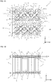
- a battery pack 1 includes two battery modules 1A and 1B, and a printed circuit board (hereinafter, referred to as "PCB") 15.
- the battery module 1A includes eight batteries 11, and tabs 12, 13, 17, and 18. Note that, the battery module 1B also has a similar configuration to that of the battery module 1A.
- the battery 11 is, for example, a rechargeable secondary battery.
- a lithium-ion battery, a nickel-hydrogen battery, a nickel-cadmium battery, or the like can be used.
- Each of the eight batteries 11 constituting the battery module 1A or 1B is a so-called cylindrical battery having a cylindrical housing, and has a positive electrode terminal 11a as an electrode terminal provided on one end portion in an axial J1 direction, and a negative electrode terminal 11b as an electrode terminal provided on another end portion in the axial J1 direction. Further, the eight batteries 11 constituting the battery module 1A or 1B are arranged in a lattice shape in posture such that the axial J1 directions are parallel to each other.
- the eight batteries 11 include the first set configured with the four batteries arranged in parallel in the X-axis direction, and the second set configured with the four batteries 11 arranged in parallel in the X-axis direction, and arranged adjacent to the first set in the Y-axis direction. Further, as illustrated in Fig. 2 , the eight batteries 11 are arranged at equal intervals so that a shortest distance between the batteries 11 adjacent to each other is a distance W2.
- the four batteries 11 arranged in parallel in the row direction on a -Y direction side are arranged in posture where directions heading from the positive electrode terminals 11a toward the respective negative electrode terminals 11b in the axial J1 direction are the same.
- all directions heading from the positive electrode terminals 11a toward the respective negative electrode terminals 11b of the four batteries 11 arranged in parallel in the row direction on the -Y direction side of each of the battery modules 1A and 1B coincide with each other in a +Z direction.
- the four batteries 11 arranged in parallel in the row direction on the -Y direction side are arranged in posture opposite to a direction heading from the positive electrode terminal 11a toward the negative electrode terminal 11b in the axial J1 direction in each of the four batteries 11 arranged adjacent on a +Y direction side and arranged in parallel in the row direction.
- all directions heading from the positive electrode terminals 11a toward the respective negative electrode terminals 11b of the four batteries 11 arranged in parallel in the row direction on the +Y direction side of each of the battery modules 1A and 1B coincide with each other in a -Z direction.
- Each of the tabs 12 and 13 is formed of a metal plate made of Cu, Al, or the like. One end portions of the respective tabs 12 and 13 are fixed to the PCB 15, and electrically connected to each other through a conductive pattern (not illustrated) formed on the PCB 15. Note that, the tabs 12 and 13 may be electrically connected to each other through a resistor (not illustrated) mounted on the PCB 15. Further, the tabs 12 and 13 intersect each other at three positions, when viewed in plan from the axial J1 direction of each of the eight batteries 11. Then, as illustrated in Fig.
- the eight batteries 11 configuring the battery module 1A or 1B are connected in the configuration of four parallel sets of two batteries in series by the tabs 12 and 13 connecting the positive electrode terminals 11a to the negative electrode terminals 11b provided in the batteries 11.
- the tab 12 is a first tab having connection pieces 12a, 12b, and 12d and an extension piece 12c.
- the connection piece 12a or 12d connects the positive electrode terminal 11a of the battery 11 arranged on the -Y direction side of the battery module 1A or 1B to the negative electrode terminal 11b of the battery 11 arranged on a +X direction side and the +Y direction side with respect to that battery 11.
- connection piece 12b connects the positive electrode terminal 11a of the battery 11 arranged on the -Y direction side to the negative electrode terminal 11b of the battery 11 arranged on a -X direction side and the +Y direction side with respect to that battery 11.
- the extension piece 12c extends in the -X direction from an end portion of the connection piece 12a located closest to the - X direction side, on an opposite side to a side continuous with the connection piece 12b.
- the tab 13 is a second tab having connection pieces 13a, 13b, and 13d and an extension piece 13c.
- the connection piece 13a or 13d connects the negative electrode terminal 11b of the battery 11 arranged on the +Y direction side of the battery module 1A or 1B to the positive electrode terminal 11a of the battery 11 arranged on the +X direction side and the -Y direction side with respect to that battery 11.
- the connection piece 13b connects the negative electrode terminal 11b of the battery 11 arranged on the +Y direction side to the positive electrode terminal 11a of the battery 11 arranged on the -X direction side and the -Y direction side with respect to that battery 11.
- the extension piece 13c extends in the -X direction from an end portion of the connection piece 13a located closest to the - X direction side, on an opposite side to a side continuous with the connection piece 13b. Further, as illustrated in Fig. 1B , the tab 13 is arranged on the -Z direction side of the tab 12 at a distance from the tab 12. Here, a distance H1 between the tab 12 and the tab 13 is set such that thermal resistance between the tab 12 and the tab 13 at an intersecting portion P1 where the tab 12 and the tab 13 intersect each other is sufficiently smaller than thermal resistance of the tab 12 and the tab 13. Note that, the tab 17 has a configuration similar to that of the tab 13, and the tab 18 has a configuration similar to that of the tab 12.
- the tab 12 is provided so as to connect any of the four batteries 11 arranged in parallel in the X-axis direction on the -Y direction side to the battery 11 other than the battery 11 having a shortest distance from any of the four batteries 11 located on the -Y direction side among the four batteries 11 adjacent in the +Y direction.
- the tab 12 connects, for example, the battery 11A and two batteries 11D other than a battery 11B having a distance from the battery 11A of a shortest distance W2 among the four batteries 11 located on the +Y direction side.
- the tab 13 is provided so as to connect any of the four batteries 11 arranged in parallel in the X-axis direction on the +Y direction side to the battery 11 other than the battery 11 having a shortest distance from any of the four batteries 11 located on the +Y direction side among the four batteries 11 adjacent in the -Y direction.
- the tab 13 connects, for example, the battery 11B and two batteries 11C other than the battery 11A having a distance from the battery 11B of the shortest distance W2 among the four batteries 11 located on the -Y direction side.
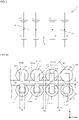
- a battery pack according to the comparative example includes a tab 19012 having a main piece 19012a with a width W3 extending in the X-axis direction, and a connection piece 19012b with the width W3 extending from a portion of the main piece 19012a corresponding to the axis J1 of the battery 11 toward the axis J1 of the battery 11.
- a heat transmission path via the tab 19012, and a heat transmission path via air present between the battery 11A and the battery 11B or 11C are formed between the battery 11A and the battery 11B or 11C.
- a heat transmission path via the tab 19012, and a heat transmission path via air present between the battery 11A and the battery 11D are formed between the battery 11A and the battery 11D.
- the shortest distance W2 between the battery 11A and the battery 11B or 11C is shorter than the shortest distance W1 between the battery 11A and the battery 11D.
- thermal resistance of the heat transmission path via air between the battery 11A and the battery 11B or 11C is smaller than thermal resistance of the heat transmission path via air between the battery 11A and the battery 11D.
- thermal resistance between the battery 11A and the battery 11B or 11C is smaller than thermal resistance between the battery 11A and the battery 11D.
- an amount of heat transmitted from the battery 11A to the battery 11D is small as indicated by an arrow AR92 in Fig. 4B .
- an amount of heat transmitted from the battery 11A to the battery 11B or 11C is large.
- heat generated in the battery 11A is intensively transmitted to the battery 11B or 11C, there is a high possibility that the battery 11B or 11C is heated to a temperature equal to or higher than an ignition temperature.
- the battery pack 1 according to the present embodiment, only a heat transmission path via air present between the battery 11A and the battery 11B or 11C is formed between the battery 11A and the battery 11B or 11C, and a heat transmission path via the tab 12 and a heat transmission path via air present between the battery 11A and the battery 11D are formed between the battery 11A and the battery 11D.
- the tab 12 is arranged at a distance from the tab 13 in the axial direction of the battery 11, and thermal resistance of the heat transmission path from the tab 12 to the tab 13 is sufficiently larger than thermal resistance of the heat transmission path via the tab 12.
- thermal resistance between the battery 11A and the battery 11B or 11C is larger than that according to the comparative example, since a heat transmission path via the tabs 12 and 13 is not formed.
- the thermal resistance between the battery 11A and the battery 11B or 11C has magnitude closer to that of thermal resistance between the battery 11A and the battery 11D than that according to the comparative example.
- an amount of heat transmitted from the battery 11A to the battery 11B or 11C decreases, while as indicated by an arrow AR12 in Fig. 5 , an amount of heat transmitted from the battery 11A to the battery 11D increases.
- heat generated in the battery 11A is uniformly transmitted to the batteries 11B, 11C, and 11D, thus an excessive temperature rise in each of the batteries 11B, 11C, and 11D is suppressed.
- the tab 12 is provided so as to connect, for example, the battery 11A and the battery 11D other than the battery 11B having a distance from the battery 11A of the shortest distance W2 among the four batteries 11 located on the +Y direction side of the battery 11A.
- the tab 13 is also provided so as to connect, for example, the battery 11B to the battery 11C other than the battery 11A having a distance from the battery 11B of the shortest distance W2 among the four batteries 11 located on the -Y direction side of the battery 11B.
- the tabs 12 and 13 are arranged at a distance in the axial J1 direction of each of the eight batteries 11. This increases thermal resistance between each of the eight batteries 11 and the other batteries 11 adjacent to each other at the shortest distance W2, for example, as compared with a case where the tabs 12 and 13 are in contact with each other. Thus, when any one of the eight batteries 11 ignites, heat generated in the ignited battery 11 is suppressed from being intensively transmitted to the other batteries 11 adjacent to that battery 11 at the shortest distance W2.
- the tabs 12 and 13 according to the present embodiment intersect each other at three positions, when viewed in plan from the axial J1 direction of each of the eight batteries 11. Accordingly, a space for arranging the tabs 12 and 13 in the housing of the battery pack 1 can be reduced, so that the battery pack 1 can be reduced in size. Further, for example, an amount of heat transmitted from the battery 11A to each of the batteries 11B, 11C, and 11D present around the battery 11A can be equalized. Thus, heat generated in the battery 11A is suppressed from being intensively transferred to the batteries 11B and 11C.
- the four batteries arranged in parallel in the row direction are arranged in posture where the directions heading from the positive electrode terminals 11a toward the respective negative electrode terminals 11b in the axial J1 direction are the same.
- the batteries 11 adjacent to each other in the column direction are arranged in posture where directions heading from the positive electrode terminals 11a toward the respective negative electrode terminals 11b in the axial J1 directions are opposite to each other. Accordingly, in each of the battery modules 1A and 1B, lengths of the respective tabs 12 and 13 connecting the eight batteries 11 in the configuration of four parallel sets of two batteries in series can be shortened, and the battery pack 1 can be reduced in size accordingly. In addition, since the lengths of the respective tabs 12 and 13 can be shortened, a power loss in the tabs 12 and 13 can be reduced accordingly.
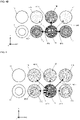
- tabs 2012 and 2013 may connect the four batteries 11 in the configuration of two parallel sets of two batteries in series.
- the tabs 2012 and 2013 intersect each other at one position, when viewed in plan from the axial J1 direction of each of the four batteries 11. Further, the tabs 2012 and 2013 are arranged at an interval in the axial J1 direction of each of the four batteries 11.
- the tabs 2012 and 2013 may be coupled to each other with a coupling portion 3014 interposed therebetween at an intersecting portion P3 where the tabs 2012 and 2013 intersect each other when viewed in plan from the axial J1 direction of each of the four batteries 11.
- the coupling portion 3014 refers to a portion where the tab 2012 and the tab 2013 are electrically connected to each other. Then, thermal resistance per unit length of the coupling portion 3014 in the Z-axis direction is larger than thermal resistance per unit length of each of the tabs 2012 and 2013 in an extending direction.
- the coupling portion 3014 may be formed by, for example, spot welding.
- the configuration including the two tabs 12 and 13 has been explained, but the present invention is not limited thereto, and for example, as in a battery pack 4001 illustrated in Fig. 7A , the six batteries 11 may be connected in the configuration of three parallel sets of two batteries in series by three tabs 4012, 4131, and 4132.
- the tab 4012, and the tabs 4131 and 4132 intersect each other at two positions when viewed in plan from the axial J1 direction of each of the six batteries 11. Further, the tab 4012, and the tabs 4131 and 4132 are arranged apart from each other in the axial J1 direction of each of the six batteries 11.
- the tab 4012, and the tabs 4131 and 4132 may be coupled to each other, with coupling portions 4141 and 4142 interposed therebetween at intersecting portions P51 and P52, respectively, where the tab 4012 and the tabs 4131 and 4132 intersect each other, when viewed in plan from the axial J1 direction of each of the six batteries 11.
- thermal resistance per unit length of each of the coupling portions 4141 and 4142 in the Z-axis direction is larger than thermal resistance per unit length of each of the tabs 4012, 4131, and 4132 in an extending direction.
- each of the coupling portions 4141 and 4142 may be formed by, for example, spot welding.
- each coupling portion 6014 may be coupled to each other with a coupling portion 6014 interposed therebetween at each intersecting portion P6 where the tabs 6012 and 6013 intersect each other when viewed in plan from the axial J1 direction of each of the eight batteries 11.
- thermal resistance per unit length of the coupling portion 6014 in the Z-axis direction is larger than thermal resistance per unit length of each of the tabs 6012 and 6013 in an extending direction.
- each coupling portion 6014 may be formed by, for example, spot welding.
- two tabs 7012 and 7013 may be connected with a conductive wire 7015 interposed therebetween which is narrower than the tabs 7012 and 7013, and whose thermal resistance per unit length is sufficiently larger than that of the tabs 7012 and 7013.
- each of the two tabs 12 and 13 has a flat plate shape
- the shape of the tab is not limited thereto.
- a tab 8012 having a flat plate shape and a tab 8013 having a recessed portion 8013a protruding toward the +Z direction side at a portion corresponding to the positive electrode terminal 11a of the battery 11 may be provided, and a side wall 8013b of the recessed portion 8013a may be erected in the Z-axis direction.
- a tab 9012 having a flat plate shape and a tab 9013 having a recessed portion 9013a protruding toward the +Z direction side at a portion corresponding to the positive electrode terminal 11a of the battery 11 may be provided, and a side wall 9013b of the recessed portion 9013a of the tab 9013 may be inclined. Further, for example, as in a battery pack 10001 illustrated in Fig.
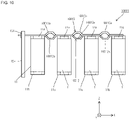
- a tab 10012 having a recessed portion 10012a protruding toward the -Z direction side at a portion corresponding to a portion between the batteries 11 adjacent to each other, and a tab 10013 having a recessed portion 10013a protruding toward the +Z direction side at a portion corresponding to a portion between the batteries 11 adjacent to each other may be provided.
- the arrangement of the eight batteries 11 is not limited thereto.
- the eight batteries 11 may be arranged in a so-called zigzag manner. That is, positions of the multiple batteries 11 may be shifted in the X-axis direction or the Y-axis direction from positions when the multiple batteries 11 are arranged in a complete lattice shape.
- the axis J1 of each of the four batteries 11 arranged in parallel in the X-axis direction on the -Y direction side may be shifted by a distance W111 in the -X direction, with respect to the axis J1 of each of the four batteries 11 adjacent in the +Y direction and arranged in parallel in the X-axis direction.
- the distance W111 is set to be less than half a distance W112 between the axes J1 of the respective two batteries 11 adjacent to each other in the X-axis direction.
- the eight batteries 11 are connected by tabs 11012 and 11013.
- each of the tabs 12 and 13 is formed of one metal plate
- the tab is not necessarily limited to being formed of one metal plate.
- a tab 12013 configured with multiple sub-tabs 12131 and 12132, and a tab 12012 configured with multiple sub-tabs 12121 and 12122 may be provided.
- each of the multiple sub-tabs 12121, 12122, 12131, and 12132 may be set to have a rectangular plate shape having the same size.
- the sub-tabs 12121, 12122, 12131, and 12132 can be separately attached, thus a degree of freedom in the attachment method can be increased accordingly.
- manufacturing efficiency of the battery pack 12001 can be increased.
- the shape of the battery 11 is not limited thereto, and the battery 11 may be, for example, a so-called prismatic battery.
- the present invention is suitable as an assembled battery including multiple batteries.
Landscapes
- Chemical & Material Sciences (AREA)
- Chemical Kinetics & Catalysis (AREA)
- Electrochemistry (AREA)
- General Chemical & Material Sciences (AREA)
- Inorganic Chemistry (AREA)
- Battery Mounting, Suspending (AREA)
- Cell Separators (AREA)
- Primary Cells (AREA)
- Battery Electrode And Active Subsutance (AREA)
- Connection Of Batteries Or Terminals (AREA)
Abstract
Description
- The present invention relates to a battery pack.
- There has been proposed a battery pack including a battery block aggregate in which multiple cylindrical secondary batteries are arranged vertically and horizontally, in posture so as to be perpendicular to a specific surface of a case, such that the secondary batteries adjacent to each other are arranged in a staggered formation, and a storage case that stores the battery block aggregate (for example, see Patent Document 1). The battery pack further includes a lead plate which is connected in common to electric power of the multiple secondary batteries configuring the battery block aggregate, and connects the multiple secondary batteries in parallel. In this battery pack, the cylindrical secondary batteries adjacent to each other are arranged in a staggered formation in a limited space in the storage case. Accordingly, even when external force is applied to the battery pack due to dropping of the battery pack onto the ground, collision between the battery packs arranged adjacent to each other, or the like, crushing of the secondary battery is suppressed, and a safe state is maintained.
- Patent Document 1:
Japanese Unexamined Patent Application Publication No. 2005-317458 - However, in the battery pack described in
Patent Document 1, since the multiple secondary batteries are arranged in a staggered formation in a limited space in the storage case, the adjacent secondary batteries are close to each other. Thus, when one secondary battery ignites, since the batteries are arranged in a limited space, heat transmitted through the lead plate, and heat transmitted through air existing in a gap generated between the secondary batteries are concentrated on the secondary battery close to the battery ignited. Accordingly, the secondary battery close to the secondary battery that has ignited first is heated to a high temperature, and as a result, secondary ignition may occur. - The present invention has been made in view of the above circumstances, and an object thereof is to provide a battery pack in which when one of multiple batteries arranged in a preset space ignites, fire spreading to the other batteries is suppressed.
- In order to achieve the above object, a battery pack according to the present invention includes multiple batteries that are tubular and arranged in posture so as to be parallel to each other, and a tab configured to electrically connect the multiple batteries to each other, wherein the multiple batteries include a first set configured with multiple batteries arranged in parallel in a first direction, and a second set configured with multiple batteries arranged in parallel in the first direction, and arranged adjacent to the first set in a second direction orthogonal to the first direction, and each of the batteries in the first set is connected to a battery other than a battery having a shortest distance among the batteries in the second set, by the tab.
- Further, in a battery pack according to the present invention, the multiple batteries may be arranged in a zigzag manner.
- Further, in a battery pack according to the present invention, the tab includes a first tab that connects respective electrode terminals of a part of the multiple batteries to each other, a second tab that connects respective electrode terminals of remaining batteries other than the part of the multiple batteries to each other, and the first tab and the second tab may intersect each other at least at one position when viewed in plan from an axial direction of each of the multiple batteries.
- Further, in a battery pack according to the present invention, the first tab and the second tab may be arranged at a distance in the axial direction of each of the multiple batteries.
- Further, in a battery pack according to the present invention, the first tab and the second tab may be electrically connected to each other at least partially, at a portion where the first tab and the second tab intersect each other when viewed in plan from the axial direction of each of the multiple batteries.
- Further, in a battery pack according to the present invention, the tab may be configured with multiple sub-tabs.
- Further, in a battery pack according to the present invention, each of the multiple batteries includes a positive electrode terminal provided on one end portion in an axial direction of each of the multiple batteries, and a negative electrode terminal provided on another end portion in the axial direction, multiple batteries arranged in parallel in the first direction may be arranged in posture where directions heading from positive electrode terminals, each of which being the positive electrode terminal of each of the multiple batteries, toward negative electrode terminals, each of which being the negative electrode terminal of each of the multiple batteries, in the axial direction are same, and are opposite to a direction heading from the positive electrode terminal toward the negative electrode terminal in the axial direction in each of the multiple batteries adjacent in the second direction and arranged in parallel in the first direction.
- According to the present invention, multiple batteries are configured with a first set configured with multiple batteries arranged in parallel in a first direction, and a second set configured with multiple batteries arranged in parallel in a first direction, and arranged adjacent to the first set in a second direction orthogonal to the first direction. Then, each of the batteries in the first set is connected by a tab to a battery other than a battery having a shortest distance among the batteries in the second set. Thus, when one battery of the multiple batteries ignites, heat is suppressed from being intensively transmitted to the battery having the shortest distance from the ignited battery. Thus, fire spreading to other batteries caused by other batteries having the shortest distance from the ignited battery being heated to high temperatures is suppressed.
-
- [
Fig. 1A] Fig. 1A is a plan view of a battery pack according to an embodiment of the present invention. - [
Fig. 1B] Fig. 1B is a side view of the battery pack according to the embodiment of the present invention. - [
Fig. 2] Fig. 2 is a plan view illustrating a part of the battery pack according to the embodiment. - [
Fig. 3] Fig. 3 is a circuit diagram of the battery pack according to the embodiment. - [
Fig. 4A] Fig. 4A is a plan view of a battery pack according to a comparative example. - [
Fig. 4B] Fig. 4B is a diagram for explaining functions of the battery pack according to the comparative example. - [
Fig. 5] Fig. 5 is a diagram for explaining functions of the battery pack according to the embodiment. - [
Fig. 6A] Fig. 6A is a plan view of a battery pack according to a modified example. - [
Fig. 6B] Fig. 6B is a plan view of a battery pack according to a modified example. - [
Fig. 6C] Fig. 6C is a side view of the battery pack according to the modified example. - [
Fig. 7A] Fig. 7A is a plan view of a battery pack according to a modified example. - [
Fig. 7B] Fig. 7B is a plan view of a battery pack according to a modified example. - [
Fig. 7C] Fig. 7C is a side view of the battery pack according to the modified example. - [
Fig. 8A] Fig. 8A is a plan view of a battery pack according to a modified example. - [
Fig. 8B] Fig. 8B is a plan view of a battery pack according to a modified example. - [
Fig. 9A] Fig. 9A is a side view of a battery pack according to a modified example. - [
Fig. 9B] Fig. 9B is a side view of a battery pack according to a modified example. - [
Fig. 10] Fig. 10 is a side view of a battery pack according to a modified example. - [
Fig. 11] Fig. 11 is a plan view of a battery pack according to a modified example. - [
Fig. 12] Fig. 12 is a plan view of a battery pack according to a modified example. - Hereinafter, an embodiment of the present invention will be described in detail with reference to the drawings. A battery pack according to the present embodiment has multiple batteries that are tubular and arranged in posture so as to be in parallel to each other, and a tab for electrically connecting the multiple batteries to each other. Additionally, the multiple batteries include a first set configured with multiple batteries arranged in parallel in a first direction, and a second set configured with multiple batteries arranged in parallel in the first direction, and arranged adjacent to the first set in a second direction orthogonal to the first direction. Each of the batteries in the first set is connected by the tab to a battery other than a battery having a shortest distance among the batteries in the second set.
- As illustrated in
Fig. 1A and Fig. 1B , abattery pack 1 according to the present embodiment includes twobattery modules battery module 1A includes eightbatteries 11, andtabs battery module 1B also has a similar configuration to that of thebattery module 1A. - The
battery 11 is, for example, a rechargeable secondary battery. As the secondary battery, a lithium-ion battery, a nickel-hydrogen battery, a nickel-cadmium battery, or the like can be used. Each of the eightbatteries 11 constituting thebattery module positive electrode terminal 11a as an electrode terminal provided on one end portion in an axial J1 direction, and anegative electrode terminal 11b as an electrode terminal provided on another end portion in the axial J1 direction. Further, the eightbatteries 11 constituting thebattery module battery module batteries 11 arranged in parallel in an X-axis direction, which is the first direction, that is, a row direction, are arranged in parallel in two columns in a Y-axis direction, which is the second direction, that is, a column direction. That is, the eightbatteries 11 include the first set configured with the four batteries arranged in parallel in the X-axis direction, and the second set configured with the fourbatteries 11 arranged in parallel in the X-axis direction, and arranged adjacent to the first set in the Y-axis direction. Further, as illustrated inFig. 2 , the eightbatteries 11 are arranged at equal intervals so that a shortest distance between thebatteries 11 adjacent to each other is a distance W2. - In addition, in the
battery module batteries 11 arranged in parallel in the row direction on a -Y direction side are arranged in posture where directions heading from thepositive electrode terminals 11a toward the respectivenegative electrode terminals 11b in the axial J1 direction are the same. To be specific, all directions heading from thepositive electrode terminals 11a toward the respectivenegative electrode terminals 11b of the fourbatteries 11 arranged in parallel in the row direction on the -Y direction side of each of thebattery modules battery module batteries 11 arranged in parallel in the row direction on the -Y direction side are arranged in posture opposite to a direction heading from thepositive electrode terminal 11a toward thenegative electrode terminal 11b in the axial J1 direction in each of the fourbatteries 11 arranged adjacent on a +Y direction side and arranged in parallel in the row direction. To be specific, all directions heading from thepositive electrode terminals 11a toward the respectivenegative electrode terminals 11b of the fourbatteries 11 arranged in parallel in the row direction on the +Y direction side of each of thebattery modules - Each of the
tabs respective tabs PCB 15, and electrically connected to each other through a conductive pattern (not illustrated) formed on thePCB 15. Note that, thetabs PCB 15. Further, thetabs batteries 11. Then, as illustrated inFig. 3 , the eightbatteries 11 configuring thebattery module tabs positive electrode terminals 11a to thenegative electrode terminals 11b provided in thebatteries 11. As illustrated inFig. 1A , thetab 12 is a first tab havingconnection pieces extension piece 12c. Here, theconnection piece positive electrode terminal 11a of thebattery 11 arranged on the -Y direction side of thebattery module negative electrode terminal 11b of thebattery 11 arranged on a +X direction side and the +Y direction side with respect to thatbattery 11. Theconnection piece 12b connects thepositive electrode terminal 11a of thebattery 11 arranged on the -Y direction side to thenegative electrode terminal 11b of thebattery 11 arranged on a -X direction side and the +Y direction side with respect to thatbattery 11. Theextension piece 12c extends in the -X direction from an end portion of theconnection piece 12a located closest to the - X direction side, on an opposite side to a side continuous with theconnection piece 12b. - The
tab 13 is a second tab havingconnection pieces extension piece 13c. Theconnection piece negative electrode terminal 11b of thebattery 11 arranged on the +Y direction side of thebattery module positive electrode terminal 11a of thebattery 11 arranged on the +X direction side and the -Y direction side with respect to thatbattery 11. The connection piece 13b connects thenegative electrode terminal 11b of thebattery 11 arranged on the +Y direction side to thepositive electrode terminal 11a of thebattery 11 arranged on the -X direction side and the -Y direction side with respect to thatbattery 11. Theextension piece 13c extends in the -X direction from an end portion of theconnection piece 13a located closest to the - X direction side, on an opposite side to a side continuous with the connection piece 13b. Further, as illustrated inFig. 1B , thetab 13 is arranged on the -Z direction side of thetab 12 at a distance from thetab 12. Here, a distance H1 between thetab 12 and thetab 13 is set such that thermal resistance between thetab 12 and thetab 13 at an intersecting portion P1 where thetab 12 and thetab 13 intersect each other is sufficiently smaller than thermal resistance of thetab 12 and thetab 13. Note that, thetab 17 has a configuration similar to that of thetab 13, and thetab 18 has a configuration similar to that of thetab 12. - Incidentally, as illustrated in
Fig. 2 , thetab 12 is provided so as to connect any of the fourbatteries 11 arranged in parallel in the X-axis direction on the -Y direction side to thebattery 11 other than thebattery 11 having a shortest distance from any of the fourbatteries 11 located on the -Y direction side among the fourbatteries 11 adjacent in the +Y direction. Thetab 12 connects, for example, thebattery 11A and twobatteries 11D other than abattery 11B having a distance from thebattery 11A of a shortest distance W2 among the fourbatteries 11 located on the +Y direction side. Thetab 13 is provided so as to connect any of the fourbatteries 11 arranged in parallel in the X-axis direction on the +Y direction side to thebattery 11 other than thebattery 11 having a shortest distance from any of the fourbatteries 11 located on the +Y direction side among the fourbatteries 11 adjacent in the -Y direction. Thetab 13 connects, for example, thebattery 11B and twobatteries 11C other than thebattery 11A having a distance from thebattery 11B of the shortest distance W2 among the fourbatteries 11 located on the -Y direction side. - Here, a function of the
battery pack 1 according to the present embodiment will be described in comparison with a comparative example. As illustrated inFig. 4A , a battery pack according to the comparative example includes atab 19012 having amain piece 19012a with a width W3 extending in the X-axis direction, and aconnection piece 19012b with the width W3 extending from a portion of themain piece 19012a corresponding to the axis J1 of thebattery 11 toward the axis J1 of thebattery 11. In the battery pack according to the comparative example, a heat transmission path via thetab 19012, and a heat transmission path via air present between thebattery 11A and thebattery battery 11A and thebattery tab 19012, and a heat transmission path via air present between thebattery 11A and thebattery 11D are formed between thebattery 11A and thebattery 11D. Here, the shortest distance W2 between thebattery 11A and thebattery battery 11A and thebattery 11D. Thus, thermal resistance of the heat transmission path via air between thebattery 11A and thebattery battery 11A and thebattery 11D. Thus, thermal resistance between thebattery 11A and thebattery battery 11A and thebattery 11D. Thus, for example, when thebattery 11A ignites and a large amount of heat is generated, an amount of heat transmitted from thebattery 11A to thebattery 11D is small as indicated by an arrow AR92 inFig. 4B . On the other hand, as indicated by an arrow AR91 inFig. 4B , an amount of heat transmitted from thebattery 11A to thebattery battery 11A is intensively transmitted to thebattery battery - On the other hand, in the
battery pack 1 according to the present embodiment, only a heat transmission path via air present between thebattery 11A and thebattery battery 11A and thebattery tab 12 and a heat transmission path via air present between thebattery 11A and thebattery 11D are formed between thebattery 11A and thebattery 11D. Note that, thetab 12 is arranged at a distance from thetab 13 in the axial direction of thebattery 11, and thermal resistance of the heat transmission path from thetab 12 to thetab 13 is sufficiently larger than thermal resistance of the heat transmission path via thetab 12. For this reason, thermal resistance between thebattery 11A and thebattery tabs battery 11A and thebattery battery 11A and thebattery 11D than that according to the comparative example. Thus, for example, when thebattery 11A ignites and a large amount of heat is generated, as indicated by an arrow AR11 inFig. 5 , an amount of heat transmitted from thebattery 11A to thebattery Fig. 5 , an amount of heat transmitted from thebattery 11A to thebattery 11D increases. As a result, heat generated in thebattery 11A is uniformly transmitted to thebatteries batteries - As described above, according to the
battery pack 1 according to the present embodiment, thetab 12 is provided so as to connect, for example, thebattery 11A and thebattery 11D other than thebattery 11B having a distance from thebattery 11A of the shortest distance W2 among the fourbatteries 11 located on the +Y direction side of thebattery 11A. Thetab 13 is also provided so as to connect, for example, thebattery 11B to thebattery 11C other than thebattery 11A having a distance from thebattery 11B of the shortest distance W2 among the fourbatteries 11 located on the -Y direction side of thebattery 11B. Accordingly, for example, when thebattery 11A ignites, heat is suppressed from being intensively transmitted to thebattery battery 11A. Thus, fire spreading to thebattery battery battery 11A being heated to a high temperature is suppressed. - Further, the
tabs batteries 11. This increases thermal resistance between each of the eightbatteries 11 and theother batteries 11 adjacent to each other at the shortest distance W2, for example, as compared with a case where thetabs batteries 11 ignites, heat generated in the ignitedbattery 11 is suppressed from being intensively transmitted to theother batteries 11 adjacent to thatbattery 11 at the shortest distance W2. - Further, the
tabs batteries 11. Accordingly, a space for arranging thetabs battery pack 1 can be reduced, so that thebattery pack 1 can be reduced in size. Further, for example, an amount of heat transmitted from thebattery 11A to each of thebatteries battery 11A can be equalized. Thus, heat generated in thebattery 11A is suppressed from being intensively transferred to thebatteries - Further, among the eight batteries according to the present embodiment, the four batteries arranged in parallel in the row direction are arranged in posture where the directions heading from the
positive electrode terminals 11a toward the respectivenegative electrode terminals 11b in the axial J1 direction are the same. Further, thebatteries 11 adjacent to each other in the column direction are arranged in posture where directions heading from thepositive electrode terminals 11a toward the respectivenegative electrode terminals 11b in the axial J1 directions are opposite to each other. Accordingly, in each of thebattery modules respective tabs batteries 11 in the configuration of four parallel sets of two batteries in series can be shortened, and thebattery pack 1 can be reduced in size accordingly. In addition, since the lengths of therespective tabs tabs - Although the embodiment of the present invention has been explained above, the present invention is not limited to the configuration of the above-described embodiment. For example, as in a
battery pack 2001 illustrated inFig. 6A ,tabs batteries 11 in the configuration of two parallel sets of two batteries in series. Thetabs batteries 11. Further, thetabs batteries 11. Alternatively, as in abattery pack 3001 illustrated inFig. 6B andFig. 6C , thetabs coupling portion 3014 interposed therebetween at an intersecting portion P3 where thetabs batteries 11. Thecoupling portion 3014 refers to a portion where thetab 2012 and thetab 2013 are electrically connected to each other. Then, thermal resistance per unit length of thecoupling portion 3014 in the Z-axis direction is larger than thermal resistance per unit length of each of thetabs coupling portion 3014 may be formed by, for example, spot welding. - In the embodiment, the configuration including the two
tabs battery pack 4001 illustrated inFig. 7A , the sixbatteries 11 may be connected in the configuration of three parallel sets of two batteries in series by threetabs tab 4012, and thetabs batteries 11. Further, thetab 4012, and thetabs batteries 11. Alternatively, as in abattery pack 5001 illustrated inFig. 7B andFig. 7C , thetab 4012, and thetabs coupling portions tab 4012 and thetabs batteries 11. Here, thermal resistance per unit length of each of thecoupling portions tabs coupling portions - Although the example in which the two
tabs battery pack 6001 illustrated inFig. 8A ,tabs coupling portion 6014 interposed therebetween at each intersecting portion P6 where thetabs batteries 11. Here, thermal resistance per unit length of thecoupling portion 6014 in the Z-axis direction is larger than thermal resistance per unit length of each of thetabs coupling portion 6014 may be formed by, for example, spot welding. - In the embodiment, the example in which the two
tabs PCB 15 has been explained, but the present invention is not limited thereto. For example, as in abattery pack 7001 illustrated inFig. 8B , twotabs 7012 and 7013 may be connected with aconductive wire 7015 interposed therebetween which is narrower than thetabs 7012 and 7013, and whose thermal resistance per unit length is sufficiently larger than that of thetabs 7012 and 7013. - Although the example in which each of the two
tabs battery pack 8001 illustrated inFig. 9A , atab 8012 having a flat plate shape and atab 8013 having a recessedportion 8013a protruding toward the +Z direction side at a portion corresponding to thepositive electrode terminal 11a of thebattery 11 may be provided, and aside wall 8013b of the recessedportion 8013a may be erected in the Z-axis direction. Alternatively, as in abattery pack 9001 illustrated inFig. 9B , atab 9012 having a flat plate shape and atab 9013 having a recessedportion 9013a protruding toward the +Z direction side at a portion corresponding to thepositive electrode terminal 11a of thebattery 11 may be provided, and aside wall 9013b of the recessedportion 9013a of thetab 9013 may be inclined. Further, for example, as in abattery pack 10001 illustrated inFig. 10 , atab 10012 having a recessedportion 10012a protruding toward the -Z direction side at a portion corresponding to a portion between thebatteries 11 adjacent to each other, and atab 10013 having a recessedportion 10013a protruding toward the +Z direction side at a portion corresponding to a portion between thebatteries 11 adjacent to each other may be provided. - Although the example in which the eight
batteries 11 are arranged in parallel in a lattice shape has been explained in the embodiment, the arrangement of the eightbatteries 11 is not limited thereto. For example, the eightbatteries 11 may be arranged in a so-called zigzag manner. That is, positions of themultiple batteries 11 may be shifted in the X-axis direction or the Y-axis direction from positions when themultiple batteries 11 are arranged in a complete lattice shape. For example, as in abattery pack 11001 illustrated inFig. 11 , the axis J1 of each of the fourbatteries 11 arranged in parallel in the X-axis direction on the -Y direction side may be shifted by a distance W111 in the -X direction, with respect to the axis J1 of each of the fourbatteries 11 adjacent in the +Y direction and arranged in parallel in the X-axis direction. Here, the distance W111 is set to be less than half a distance W112 between the axes J1 of the respective twobatteries 11 adjacent to each other in the X-axis direction. Here, the eightbatteries 11 are connected bytabs - According to this configuration, while the shortest distance W2 between the
batteries 11 adjacent to each other is maintained, it is possible to reduce a distance in the Y-axis direction between a set of the fourbatteries 11 arranged in parallel in the X-axis direction on the -Y direction side, and a set of the fourbatteries 11 arranged in parallel in the X-axis direction on the +Y direction side. Thus, a size of thebattery pack 11001 can be reduced. - In the embodiment, the example in which each of the
tabs battery pack 12001 illustrated inFig. 12 , atab 12013 configured withmultiple sub-tabs tab 12012 configured withmultiple sub-tabs multiple sub-tabs - According to this configuration, when the
tabs positive electrode terminal 11a or thenegative electrode terminal 11b of thebattery 11, the sub-tabs 12121, 12122, 12131, and 12132 can be separately attached, thus a degree of freedom in the attachment method can be increased accordingly. Thus, manufacturing efficiency of thebattery pack 12001 can be increased. In addition, even when the number ofbatteries 11 connected in parallel is changed, it is possible to cope with the change by changing the number ofsub-tabs tabs tabs - Although the example in which the
battery 11 is a so-called cylindrical battery has been explained in the embodiment, the shape of thebattery 11 is not limited thereto, and thebattery 11 may be, for example, a so-called prismatic battery. - The embodiment and the modified examples of the present invention (including those described after "Note that", the same applies hereinafter) have been explained above, but the present invention is not limited thereto. The present invention includes those in which the embodiment and the modified examples are appropriately combined and those in which changes are appropriately added thereto.
- The present application is based on
Japanese Patent Application No. 2019-148029 filed on Aug. 9, 2019 Japanese Patent Application No. 2019-148029 - The present invention is suitable as an assembled battery including multiple batteries.
-
- 1, 2001, 3001, 4001, 5001, 6001, 7001, 8001, 9001, 10001, 11001, 12001 BATTERY PACK
- 1A, 1B BATTERY MODULE
- 11, 11A, 11B, 11C, 11D BATTERY
- 11a POSITIVE ELECTRODE TERMINAL
- 11b NEGATIVE ELECTRODE TERMINAL
- 12, 13, 17, 18, 2012, 2013, 4012, 4131, 4132, 5012, 5131, 5132, 6012, 6013, 7012, 7013, 8012, 8013, 9012, 9013, 10012, 10013, 11012, 11013, 12012, 12013 TAB
- 12a, 12b, 12d, 13a, 13b, 13d CONNECTION PIECE
- 12c, 13c EXTENSION PIECE
- 15 PCB
- 3014, 5141, 5142, 6014 COUPLING PORTION
- 7015 CONDUCTIVE WIRE
- 8013a, 9013a, 10012a, 10013a RECESSED PORTION
- 8013b, 9013b SIDE WALL
- 12121, 12122, 12131, 12132 SUB-TAB
- J1 AXIS
- P1, P3, P6, P51, P52 INTERSECTING PORTION
Claims (7)
- A battery pack, comprising:multiple batteries that are tubular and arranged in posture so as to be parallel to each other, anda tab configured to electrically connect the multiple batteries to each other,wherein the multiple batteries includea first set configured with multiple batteries arranged in parallel in a first direction, anda second set configured with multiple batteries arranged in parallel in the first direction, and arranged adjacent to the first set in a second direction orthogonal to the first direction, andeach of the batteries in the first set is connected to a battery other than a battery having a shortest distance among the batteries in the second set, by the tab.
- The battery pack according to Claim 1,
wherein the multiple batteries are arranged in a zigzag manner. - The battery pack according to Claim 1 or 2,
wherein the tab includesa first tab that connects respective electrode terminals of a part of the multiple batteries to each other, anda second tab that connects respective electrode terminals of remaining batteries other than the part of the multiple batteries to each other, andthe first tab and the second tab intersect each other at least at one position when viewed in plan from an axial direction of each of the multiple batteries. - The battery pack according to Claim 3,
wherein the first tab and the second tab are arranged at a distance in the axial direction of each of the multiple batteries. - The battery pack according to Claim 4,
wherein the first tab and the second tab are electrically connected to each other at least partially, at a portion where the first tab and the second tab intersect each other when viewed in plan from the axial direction of each of the multiple batteries. - The battery pack according to any one of Claims 1 to 5, wherein the tab is configured with multiple sub-tabs.
- The battery pack according to any one of Claims 1 to 6,wherein each of the multiple batteries includes a positive electrode terminal provided on one end portion in an axial direction of each of the multiple batteries, and a negative electrode terminal provided on another end portion in the axial direction,multiple batteries arranged in parallel in the first direction are arranged in posture where directions heading from positive electrode terminals, each of which being the positive electrode terminal of each of the multiple batteries, toward negative electrode terminals, each of which being the negative electrode terminal of each of the multiple batteries, in the axial direction are same, and are opposite to a direction heading from the positive electrode terminal toward the negative electrode terminal in the axial direction in each of the multiple batteries adjacent in the second direction and arranged in parallel in the first direction.
Applications Claiming Priority (2)
| Application Number | Priority Date | Filing Date | Title |
|---|---|---|---|
| JP2019148029 | 2019-08-09 | ||
| PCT/JP2020/029878 WO2021029284A1 (en) | 2019-08-09 | 2020-08-04 | Battery pack |
Publications (2)
| Publication Number | Publication Date |
|---|---|
| EP3996189A1 true EP3996189A1 (en) | 2022-05-11 |
| EP3996189A4 EP3996189A4 (en) | 2024-11-06 |
Family
ID=74570282
Family Applications (1)
| Application Number | Title | Priority Date | Filing Date |
|---|---|---|---|
| EP20853298.6A Pending EP3996189A4 (en) | 2019-08-09 | 2020-08-04 | BATTERY PACK |
Country Status (5)
| Country | Link |
|---|---|
| US (1) | US12308451B2 (en) |
| EP (1) | EP3996189A4 (en) |
| JP (1) | JP7056805B2 (en) |
| CN (1) | CN114175372B (en) |
| WO (1) | WO2021029284A1 (en) |
Family Cites Families (15)
| Publication number | Priority date | Publication date | Assignee | Title |
|---|---|---|---|---|
| JP4163419B2 (en) * | 2002-01-23 | 2008-10-08 | 本田技研工業株式会社 | Connection structure of positive electrode and negative electrode in battery assembly |
| JP4761726B2 (en) * | 2004-04-30 | 2011-08-31 | 三洋電機株式会社 | Pack battery |
| EP1921696A1 (en) * | 2006-11-10 | 2008-05-14 | Hitachi Vehicle Energy, Ltd. | Battery pack and method for welding cells |
| JP2010282811A (en) | 2009-06-04 | 2010-12-16 | Sanyo Electric Co Ltd | Pack battery |
| KR101057531B1 (en) * | 2010-05-07 | 2011-08-17 | 삼성에스디아이 주식회사 | Battery pack |
| US20140234668A1 (en) | 2013-02-19 | 2014-08-21 | Faster Faster, Inc. | Battery Housing with Single-Side Electrical Interconnects |
| JP6149550B2 (en) | 2013-07-02 | 2017-06-21 | ソニー株式会社 | Power storage device, power storage system, electronic device, electric vehicle, and power system |
| WO2016147280A1 (en) * | 2015-03-13 | 2016-09-22 | 株式会社東芝 | Battery pack and battery pack device |
| WO2017047258A1 (en) * | 2015-09-14 | 2017-03-23 | 日立オートモティブシステムズ株式会社 | Battery pack |
| JP2018005984A (en) * | 2016-06-27 | 2018-01-11 | 日立オートモティブシステムズ株式会社 | Power storage module |
| WO2018003467A1 (en) * | 2016-06-29 | 2018-01-04 | パナソニックIpマネジメント株式会社 | Battery block and battery module |
| CN105914320A (en) * | 2016-07-04 | 2016-08-31 | 河南森源重工有限公司 | Cylindrical battery module for electric automobile |
| KR102587699B1 (en) * | 2016-08-03 | 2023-10-11 | 삼성에스디아이 주식회사 | Battery Pack |
| CN106784563B (en) * | 2016-12-24 | 2023-07-07 | 东莞市卓安精机自动化设备有限公司 | Lithium battery module busbar connection structure |
| JP2019148029A (en) | 2018-02-27 | 2019-09-05 | カジレーネ株式会社 | Manufacturing method and manufacturing apparatus of split yarn of carbon fiber |
-
2020
- 2020-08-04 JP JP2021539226A patent/JP7056805B2/en active Active
- 2020-08-04 EP EP20853298.6A patent/EP3996189A4/en active Pending
- 2020-08-04 WO PCT/JP2020/029878 patent/WO2021029284A1/en not_active Ceased
- 2020-08-04 CN CN202080054478.6A patent/CN114175372B/en active Active
-
2022
- 2022-02-08 US US17/666,622 patent/US12308451B2/en active Active
Also Published As
| Publication number | Publication date |
|---|---|
| EP3996189A4 (en) | 2024-11-06 |
| US12308451B2 (en) | 2025-05-20 |
| US20220158285A1 (en) | 2022-05-19 |
| JPWO2021029284A1 (en) | 2021-02-18 |
| CN114175372A (en) | 2022-03-11 |
| JP7056805B2 (en) | 2022-04-19 |
| WO2021029284A1 (en) | 2021-02-18 |
| CN114175372B (en) | 2024-03-19 |
Similar Documents
| Publication | Publication Date | Title |
|---|---|---|
| EP1991880B1 (en) | Voltage sensing member and battery module employed with the same | |
| US9413084B2 (en) | Secondary battery pack based on mechanical connection manner | |
| US8795877B2 (en) | Electrical connecting member of assembling type and secondary battery pack containing the same | |
| CN107851749B (en) | Battery module having structure in which battery management system is directly connected to terminal board | |
| KR102711055B1 (en) | Battery module and battery pack including the same | |
| US11942660B2 (en) | Battery pack | |
| KR102082497B1 (en) | Fuse assembly structure of secondary battery pack | |
| EP3940867A1 (en) | Battery pack having reinforced short-circuit prevention and shock protection structure | |
| KR102472233B1 (en) | Battery module | |
| KR102436424B1 (en) | Battery module | |
| US11342633B2 (en) | Current collecting system for battery module, battery module, and vehicle | |
| JP7605413B2 (en) | Battery module and battery pack including same | |
| CN211578874U (en) | Battery | |
| KR102272268B1 (en) | Current collector system for battery module, battery module, and vehicle | |
| US12308451B2 (en) | Battery pack | |
| JP2020528649A (en) | Battery module and battery pack | |
| US12431592B2 (en) | Battery pack | |
| US12603332B2 (en) | Battery pack comprising cell stack structure using flexible printed circuit board | |
| KR20240017739A (en) | Battery moudle | |
| KR20140109174A (en) | Battery pack and battery module having the same | |
| EP4428999B1 (en) | Battery pack busbar | |
| KR20240121614A (en) | Busbar for a Battery Module and Battery Module comprising the same | |
| JP2024518468A (en) | Battery module and battery pack including same | |
| CN119585928A (en) | Battery module |
Legal Events
| Date | Code | Title | Description |
|---|---|---|---|
| STAA | Information on the status of an ep patent application or granted ep patent |
Free format text: STATUS: THE INTERNATIONAL PUBLICATION HAS BEEN MADE |
|
| PUAI | Public reference made under article 153(3) epc to a published international application that has entered the european phase |
Free format text: ORIGINAL CODE: 0009012 |
|
| STAA | Information on the status of an ep patent application or granted ep patent |
Free format text: STATUS: REQUEST FOR EXAMINATION WAS MADE |
|
| 17P | Request for examination filed |
Effective date: 20220202 |
|
| AK | Designated contracting states |
Kind code of ref document: A1 Designated state(s): AL AT BE BG CH CY CZ DE DK EE ES FI FR GB GR HR HU IE IS IT LI LT LU LV MC MK MT NL NO PL PT RO RS SE SI SK SM TR |
|
| DAV | Request for validation of the european patent (deleted) | ||
| DAX | Request for extension of the european patent (deleted) | ||
| A4 | Supplementary search report drawn up and despatched |
Effective date: 20241008 |
|
| RIC1 | Information provided on ipc code assigned before grant |
Ipc: H01M 50/522 20210101ALI20241001BHEP Ipc: H01M 50/503 20210101ALI20241001BHEP Ipc: H01M 50/213 20210101ALI20241001BHEP Ipc: H01M 50/50 20210101ALI20241001BHEP Ipc: H01M 50/20 20210101AFI20241001BHEP |
|
| STAA | Information on the status of an ep patent application or granted ep patent |
Free format text: STATUS: EXAMINATION IS IN PROGRESS |
|
| 17Q | First examination report despatched |
Effective date: 20260319 |