EP3996186A1 - Battery and manufacturing method therefor - Google Patents
Battery and manufacturing method therefor Download PDFInfo
- Publication number
- EP3996186A1 EP3996186A1 EP21206015.6A EP21206015A EP3996186A1 EP 3996186 A1 EP3996186 A1 EP 3996186A1 EP 21206015 A EP21206015 A EP 21206015A EP 3996186 A1 EP3996186 A1 EP 3996186A1
- Authority
- EP
- European Patent Office
- Prior art keywords
- winding
- positive electrode
- negative electrode
- electrode
- sealing plate
- Prior art date
- Legal status (The legal status is an assumption and is not a legal conclusion. Google has not performed a legal analysis and makes no representation as to the accuracy of the status listed.)
- Granted
Links
Images





Classifications
-
- H—ELECTRICITY
- H01—ELECTRIC ELEMENTS
- H01M—PROCESSES OR MEANS, e.g. BATTERIES, FOR THE DIRECT CONVERSION OF CHEMICAL ENERGY INTO ELECTRICAL ENERGY
- H01M10/00—Secondary cells; Manufacture thereof
- H01M10/04—Construction or manufacture in general
- H01M10/0413—Large-sized flat cells or batteries for motive or stationary systems with plate-like electrodes
-
- H—ELECTRICITY
- H01—ELECTRIC ELEMENTS
- H01M—PROCESSES OR MEANS, e.g. BATTERIES, FOR THE DIRECT CONVERSION OF CHEMICAL ENERGY INTO ELECTRICAL ENERGY
- H01M50/00—Constructional details or processes of manufacture of the non-active parts of electrochemical cells other than fuel cells, e.g. hybrid cells
- H01M50/50—Current conducting connections for cells or batteries
- H01M50/572—Means for preventing undesired use or discharge
- H01M50/584—Means for preventing undesired use or discharge for preventing incorrect connections inside or outside the batteries
- H01M50/59—Means for preventing undesired use or discharge for preventing incorrect connections inside or outside the batteries characterised by the protection means
- H01M50/597—Protection against reversal of polarity
-
- H—ELECTRICITY
- H01—ELECTRIC ELEMENTS
- H01M—PROCESSES OR MEANS, e.g. BATTERIES, FOR THE DIRECT CONVERSION OF CHEMICAL ENERGY INTO ELECTRICAL ENERGY
- H01M10/00—Secondary cells; Manufacture thereof
- H01M10/04—Construction or manufacture in general
- H01M10/0431—Cells with wound or folded electrodes
-
- H—ELECTRICITY
- H01—ELECTRIC ELEMENTS
- H01M—PROCESSES OR MEANS, e.g. BATTERIES, FOR THE DIRECT CONVERSION OF CHEMICAL ENERGY INTO ELECTRICAL ENERGY
- H01M10/00—Secondary cells; Manufacture thereof
- H01M10/04—Construction or manufacture in general
- H01M10/0468—Compression means for stacks of electrodes and separators
-
- H—ELECTRICITY
- H01—ELECTRIC ELEMENTS
- H01M—PROCESSES OR MEANS, e.g. BATTERIES, FOR THE DIRECT CONVERSION OF CHEMICAL ENERGY INTO ELECTRICAL ENERGY
- H01M10/00—Secondary cells; Manufacture thereof
- H01M10/04—Construction or manufacture in general
- H01M10/0472—Vertically superposed cells with vertically disposed plates
-
- H—ELECTRICITY
- H01—ELECTRIC ELEMENTS
- H01M—PROCESSES OR MEANS, e.g. BATTERIES, FOR THE DIRECT CONVERSION OF CHEMICAL ENERGY INTO ELECTRICAL ENERGY
- H01M10/00—Secondary cells; Manufacture thereof
- H01M10/04—Construction or manufacture in general
- H01M10/049—Processes for forming or storing electrodes in the battery container
-
- H—ELECTRICITY
- H01—ELECTRIC ELEMENTS
- H01M—PROCESSES OR MEANS, e.g. BATTERIES, FOR THE DIRECT CONVERSION OF CHEMICAL ENERGY INTO ELECTRICAL ENERGY
- H01M10/00—Secondary cells; Manufacture thereof
- H01M10/05—Accumulators with non-aqueous electrolyte
- H01M10/052—Li-accumulators
- H01M10/0525—Rocking-chair batteries, i.e. batteries with lithium insertion or intercalation in both electrodes; Lithium-ion batteries
-
- H—ELECTRICITY
- H01—ELECTRIC ELEMENTS
- H01M—PROCESSES OR MEANS, e.g. BATTERIES, FOR THE DIRECT CONVERSION OF CHEMICAL ENERGY INTO ELECTRICAL ENERGY
- H01M10/00—Secondary cells; Manufacture thereof
- H01M10/05—Accumulators with non-aqueous electrolyte
- H01M10/058—Construction or manufacture
- H01M10/0587—Construction or manufacture of accumulators having only wound construction elements, i.e. wound positive electrodes, wound negative electrodes and wound separators
-
- H—ELECTRICITY
- H01—ELECTRIC ELEMENTS
- H01M—PROCESSES OR MEANS, e.g. BATTERIES, FOR THE DIRECT CONVERSION OF CHEMICAL ENERGY INTO ELECTRICAL ENERGY
- H01M50/00—Constructional details or processes of manufacture of the non-active parts of electrochemical cells other than fuel cells, e.g. hybrid cells
- H01M50/10—Primary casings; Jackets or wrappings
-
- H—ELECTRICITY
- H01—ELECTRIC ELEMENTS
- H01M—PROCESSES OR MEANS, e.g. BATTERIES, FOR THE DIRECT CONVERSION OF CHEMICAL ENERGY INTO ELECTRICAL ENERGY
- H01M50/00—Constructional details or processes of manufacture of the non-active parts of electrochemical cells other than fuel cells, e.g. hybrid cells
- H01M50/10—Primary casings; Jackets or wrappings
- H01M50/102—Primary casings; Jackets or wrappings characterised by their shape or physical structure
- H01M50/103—Primary casings; Jackets or wrappings characterised by their shape or physical structure prismatic or rectangular
-
- H—ELECTRICITY
- H01—ELECTRIC ELEMENTS
- H01M—PROCESSES OR MEANS, e.g. BATTERIES, FOR THE DIRECT CONVERSION OF CHEMICAL ENERGY INTO ELECTRICAL ENERGY
- H01M50/00—Constructional details or processes of manufacture of the non-active parts of electrochemical cells other than fuel cells, e.g. hybrid cells
- H01M50/10—Primary casings; Jackets or wrappings
- H01M50/183—Sealing members
- H01M50/186—Sealing members characterised by the disposition of the sealing members
-
- H—ELECTRICITY
- H01—ELECTRIC ELEMENTS
- H01M—PROCESSES OR MEANS, e.g. BATTERIES, FOR THE DIRECT CONVERSION OF CHEMICAL ENERGY INTO ELECTRICAL ENERGY
- H01M50/00—Constructional details or processes of manufacture of the non-active parts of electrochemical cells other than fuel cells, e.g. hybrid cells
- H01M50/40—Separators; Membranes; Diaphragms; Spacing elements inside cells
-
- H—ELECTRICITY
- H01—ELECTRIC ELEMENTS
- H01M—PROCESSES OR MEANS, e.g. BATTERIES, FOR THE DIRECT CONVERSION OF CHEMICAL ENERGY INTO ELECTRICAL ENERGY
- H01M50/00—Constructional details or processes of manufacture of the non-active parts of electrochemical cells other than fuel cells, e.g. hybrid cells
- H01M50/40—Separators; Membranes; Diaphragms; Spacing elements inside cells
- H01M50/409—Separators, membranes or diaphragms characterised by the material
- H01M50/411—Organic material
- H01M50/414—Synthetic resins, e.g. thermoplastics or thermosetting resins
-
- H—ELECTRICITY
- H01—ELECTRIC ELEMENTS
- H01M—PROCESSES OR MEANS, e.g. BATTERIES, FOR THE DIRECT CONVERSION OF CHEMICAL ENERGY INTO ELECTRICAL ENERGY
- H01M50/00—Constructional details or processes of manufacture of the non-active parts of electrochemical cells other than fuel cells, e.g. hybrid cells
- H01M50/40—Separators; Membranes; Diaphragms; Spacing elements inside cells
- H01M50/409—Separators, membranes or diaphragms characterised by the material
- H01M50/431—Inorganic material
-
- H—ELECTRICITY
- H01—ELECTRIC ELEMENTS
- H01M—PROCESSES OR MEANS, e.g. BATTERIES, FOR THE DIRECT CONVERSION OF CHEMICAL ENERGY INTO ELECTRICAL ENERGY
- H01M50/00—Constructional details or processes of manufacture of the non-active parts of electrochemical cells other than fuel cells, e.g. hybrid cells
- H01M50/40—Separators; Membranes; Diaphragms; Spacing elements inside cells
- H01M50/409—Separators, membranes or diaphragms characterised by the material
- H01M50/446—Composite material consisting of a mixture of organic and inorganic materials
-
- H—ELECTRICITY
- H01—ELECTRIC ELEMENTS
- H01M—PROCESSES OR MEANS, e.g. BATTERIES, FOR THE DIRECT CONVERSION OF CHEMICAL ENERGY INTO ELECTRICAL ENERGY
- H01M50/00—Constructional details or processes of manufacture of the non-active parts of electrochemical cells other than fuel cells, e.g. hybrid cells
- H01M50/40—Separators; Membranes; Diaphragms; Spacing elements inside cells
- H01M50/471—Spacing elements inside cells other than separators, membranes or diaphragms; Manufacturing processes thereof
- H01M50/474—Spacing elements inside cells other than separators, membranes or diaphragms; Manufacturing processes thereof characterised by their position inside the cells
-
- H—ELECTRICITY
- H01—ELECTRIC ELEMENTS
- H01M—PROCESSES OR MEANS, e.g. BATTERIES, FOR THE DIRECT CONVERSION OF CHEMICAL ENERGY INTO ELECTRICAL ENERGY
- H01M50/00—Constructional details or processes of manufacture of the non-active parts of electrochemical cells other than fuel cells, e.g. hybrid cells
- H01M50/40—Separators; Membranes; Diaphragms; Spacing elements inside cells
- H01M50/471—Spacing elements inside cells other than separators, membranes or diaphragms; Manufacturing processes thereof
- H01M50/477—Spacing elements inside cells other than separators, membranes or diaphragms; Manufacturing processes thereof characterised by their shape
-
- H—ELECTRICITY
- H01—ELECTRIC ELEMENTS
- H01M—PROCESSES OR MEANS, e.g. BATTERIES, FOR THE DIRECT CONVERSION OF CHEMICAL ENERGY INTO ELECTRICAL ENERGY
- H01M50/00—Constructional details or processes of manufacture of the non-active parts of electrochemical cells other than fuel cells, e.g. hybrid cells
- H01M50/50—Current conducting connections for cells or batteries
- H01M50/531—Electrode connections inside a battery casing
- H01M50/538—Connection of several leads or tabs of wound or folded electrode stacks
-
- H—ELECTRICITY
- H01—ELECTRIC ELEMENTS
- H01M—PROCESSES OR MEANS, e.g. BATTERIES, FOR THE DIRECT CONVERSION OF CHEMICAL ENERGY INTO ELECTRICAL ENERGY
- H01M50/00—Constructional details or processes of manufacture of the non-active parts of electrochemical cells other than fuel cells, e.g. hybrid cells
- H01M50/50—Current conducting connections for cells or batteries
- H01M50/543—Terminals
- H01M50/547—Terminals characterised by the disposition of the terminals on the cells
-
- H—ELECTRICITY
- H01—ELECTRIC ELEMENTS
- H01M—PROCESSES OR MEANS, e.g. BATTERIES, FOR THE DIRECT CONVERSION OF CHEMICAL ENERGY INTO ELECTRICAL ENERGY
- H01M50/00—Constructional details or processes of manufacture of the non-active parts of electrochemical cells other than fuel cells, e.g. hybrid cells
- H01M50/50—Current conducting connections for cells or batteries
- H01M50/543—Terminals
- H01M50/552—Terminals characterised by their shape
- H01M50/553—Terminals adapted for prismatic, pouch or rectangular cells
-
- H—ELECTRICITY
- H01—ELECTRIC ELEMENTS
- H01M—PROCESSES OR MEANS, e.g. BATTERIES, FOR THE DIRECT CONVERSION OF CHEMICAL ENERGY INTO ELECTRICAL ENERGY
- H01M10/00—Secondary cells; Manufacture thereof
- H01M10/05—Accumulators with non-aqueous electrolyte
- H01M10/052—Li-accumulators
-
- H—ELECTRICITY
- H01—ELECTRIC ELEMENTS
- H01M—PROCESSES OR MEANS, e.g. BATTERIES, FOR THE DIRECT CONVERSION OF CHEMICAL ENERGY INTO ELECTRICAL ENERGY
- H01M4/00—Electrodes
- H01M4/02—Electrodes composed of, or comprising, active material
- H01M2004/026—Electrodes composed of, or comprising, active material characterised by the polarity
- H01M2004/027—Negative electrodes
-
- H—ELECTRICITY
- H01—ELECTRIC ELEMENTS
- H01M—PROCESSES OR MEANS, e.g. BATTERIES, FOR THE DIRECT CONVERSION OF CHEMICAL ENERGY INTO ELECTRICAL ENERGY
- H01M50/00—Constructional details or processes of manufacture of the non-active parts of electrochemical cells other than fuel cells, e.g. hybrid cells
- H01M50/20—Mountings; Secondary casings or frames; Racks, modules or packs; Suspension devices; Shock absorbers; Transport or carrying devices; Holders
- H01M50/233—Mountings; Secondary casings or frames; Racks, modules or packs; Suspension devices; Shock absorbers; Transport or carrying devices; Holders characterised by physical properties of casings or racks, e.g. dimensions
- H01M50/242—Mountings; Secondary casings or frames; Racks, modules or packs; Suspension devices; Shock absorbers; Transport or carrying devices; Holders characterised by physical properties of casings or racks, e.g. dimensions adapted for protecting batteries against vibrations, collision impact or swelling
-
- H—ELECTRICITY
- H01—ELECTRIC ELEMENTS
- H01M—PROCESSES OR MEANS, e.g. BATTERIES, FOR THE DIRECT CONVERSION OF CHEMICAL ENERGY INTO ELECTRICAL ENERGY
- H01M50/00—Constructional details or processes of manufacture of the non-active parts of electrochemical cells other than fuel cells, e.g. hybrid cells
- H01M50/50—Current conducting connections for cells or batteries
- H01M50/531—Electrode connections inside a battery casing
-
- H—ELECTRICITY
- H01—ELECTRIC ELEMENTS
- H01M—PROCESSES OR MEANS, e.g. BATTERIES, FOR THE DIRECT CONVERSION OF CHEMICAL ENERGY INTO ELECTRICAL ENERGY
- H01M50/00—Constructional details or processes of manufacture of the non-active parts of electrochemical cells other than fuel cells, e.g. hybrid cells
- H01M50/50—Current conducting connections for cells or batteries
- H01M50/543—Terminals
- H01M50/552—Terminals characterised by their shape
- H01M50/553—Terminals adapted for prismatic, pouch or rectangular cells
- H01M50/555—Window-shaped terminals
-
- Y—GENERAL TAGGING OF NEW TECHNOLOGICAL DEVELOPMENTS; GENERAL TAGGING OF CROSS-SECTIONAL TECHNOLOGIES SPANNING OVER SEVERAL SECTIONS OF THE IPC; TECHNICAL SUBJECTS COVERED BY FORMER USPC CROSS-REFERENCE ART COLLECTIONS [XRACs] AND DIGESTS
- Y02—TECHNOLOGIES OR APPLICATIONS FOR MITIGATION OR ADAPTATION AGAINST CLIMATE CHANGE
- Y02E—REDUCTION OF GREENHOUSE GAS [GHG] EMISSIONS, RELATED TO ENERGY GENERATION, TRANSMISSION OR DISTRIBUTION
- Y02E60/00—Enabling technologies; Technologies with a potential or indirect contribution to GHG emissions mitigation
- Y02E60/10—Energy storage using batteries
-
- Y—GENERAL TAGGING OF NEW TECHNOLOGICAL DEVELOPMENTS; GENERAL TAGGING OF CROSS-SECTIONAL TECHNOLOGIES SPANNING OVER SEVERAL SECTIONS OF THE IPC; TECHNICAL SUBJECTS COVERED BY FORMER USPC CROSS-REFERENCE ART COLLECTIONS [XRACs] AND DIGESTS
- Y02—TECHNOLOGIES OR APPLICATIONS FOR MITIGATION OR ADAPTATION AGAINST CLIMATE CHANGE
- Y02P—CLIMATE CHANGE MITIGATION TECHNOLOGIES IN THE PRODUCTION OR PROCESSING OF GOODS
- Y02P70/00—Climate change mitigation technologies in the production process for final industrial or consumer products
- Y02P70/50—Manufacturing or production processes characterised by the final manufactured product
Definitions
- the present teaching relates to a battery and a manufacturing method therefor.
- a battery including a winding electrode body in which a strip-shaped positive electrode including a positive electrode active material layer on a positive electrode collector and a strip-shaped negative electrode including a negative electrode active material layer on a negative electrode collector are laminated with each other via a strip-shaped separator and wound about a winding axis has been known (see Japanese Patent Application Laid-open No. 2017-010878 ).
- Japanese Patent No. 5100441 discloses a winding electrode body in which a plurality of tabs (lead withdrawing parts) that are a part of a positive electrode collector protrude from one end in a winding axis direction and a plurality of tabs that are a part of a negative electrode collector protrude from the other end.
- the outside surface of the winding electrode body is covered with a separator.
- the plurality of tabs are bundled together as one and welded and joined to a lead for current collection.
- a plurality of tabs have play so as to be movable in a direction crossing a direction protruding from a collector. Therefore, if vibration, shock, or the like is applied from an outside during the use of a battery or the like, a winding electrode body may contact a battery case or a component attached to the battery case. As a result, there is a possibility that a separator covering the outside surface of the winding electrode body is damaged and a positive electrode and a negative electrode are short-circuited to each other.
- the present teaching has been made in view of the above circumstances and has an object of providing a battery that prevents the short circuit between a positive electrode and a negative electrode and improves reliability and a manufacturing method for the battery.
- a battery including: an exterior body having a bottom wall, a pair of first side walls extending from the bottom wall and facing each other, a pair of second side walls extending from the bottom wall and facing each other, and an opening facing the bottom wall; a sealing plate that seals the opening of the exterior body; at least one winding electrode body in which a strip-shaped positive electrode and a strip-shaped negative electrode are laminated with each other via a strip-shaped separator and wound about a winding axis; a positive electrode tab group that includes a plurality of positive electrode tabs provided at an end in a winding axis direction of the winding electrode body and is electrically connected to the positive electrode; and a negative electrode tab group that includes a plurality of negative electrode tabs provided at an end in the winding axis direction of the winding electrode body and is electrically connected to the negative electrode.
- the winding electrode body has a flat shape having a pair of curvature parts having a curved outside surface and a flat part that connects the pair of curvature parts to each other and has a flat outside surface and is accommodated in the exterior body so that one of the curvature parts faces the sealing plate and the other thereof faces the bottom wall of the exterior body.
- a line perpendicular to the winding axis of the winding electrode body and perpendicular to the bottom wall is assumed as L1
- a portion positioned at an outermost periphery of the negative electrode in at least one of the pair of the curvature parts faces a portion positioned on a winding inner peripheral side of the negative electrode via the separator and not via the positive electrode on the line L1.
- the winding electrode body of the battery is accommodated in the exterior body so that the curvature parts face the bottom wall of the exterior body and/or the sealing plate, and the portion positioned at the outermost periphery of the negative electrode in the curvature parts facing the bottom wall of the exterior body and/or the sealing plate faces the portion positioned on the winding inner peripheral side not via the positive electrode on the line L1.
- the curvature parts contact the bottom wall and/or the sealing plate and components provided in the bottom wall and the sealing plate to cause damage on the separator, it is possible to prevent the short circuit between the portion positioned at the outermost periphery of the negative electrode and the positive electrode. Accordingly, it is possible to improve the reliability of the battery.
- the battery includes a spacer arranged between the sealing plate and the winding electrode body, and the portion positioned at the outermost periphery of the negative electrode faces the portion positioned on the winding inner peripheral side of the negative electrode via the separator and not via the positive electrode on the line L1.
- the winding electrode body is not liable to move greatly toward the sealing plate. Therefore, it is possible to prevent damage on the separator caused when the winding electrode body contacts the sealing plate. Thus, it is possible to effectively prevent the short circuit between the positive electrode and the negative electrode. Further, it is possible to reduce loads on the positive electrode tab group and/or the negative electrode tab group and stably maintain electrical connection. Thus, it is possible to improve the conduction reliability of the battery.
- the battery includes: a terminal that is attached to the sealing plate and electrically connected to the positive electrode tab group or the negative electrode tab group; a collecting part that electrically connects the positive electrode tab group or the negative electrode tab group and the terminal to each other; and an insulating member that insulates the sealing plate and the collecting part from each other and has a protrusion part protruding to a side of the winding electrode body from a side of the sealing plate, and the protrusion part of the insulating member constitutes the spacer.
- the spacer does not contact the winding electrode body.
- the spacer when the spacer is arranged at a position separated from the electrode body, it is possible to prevent the curvature parts and the spacer from rubbing against each other even if the winding electrode body moves toward the sealing plate.
- the separator is not liable to be damaged, which makes it possible to effectively prevent the short circuit between the positive electrode and the negative electrode.
- the at least one winding electrode body includes a plurality of winding electrode bodies.
- a battery including a plurality of winding electrode bodies it is especially demanded that the short circuit between a positive electrode and a negative electrode be prevented to increase reliability. Accordingly, the application of the technology disclosed here is particularly effective.
- the separator includes a resinous base material part and a heat resistance layer that is provided on the base material part and contains an inorganic filler, and the outside surface of the winding electrode body is covered with the heat resistance layer in at least one of the pair of curvature parts.
- a manufacturing method for a battery including an exterior body having a bottom wall, a pair of first side walls extending from the bottom wall and facing each other, a pair of second side walls extending from the bottom wall and facing each other, and an opening facing the bottom wall, a sealing plate that seals the opening of the exterior body, at least one winding electrode body in which a strip-shaped positive electrode and a strip-shaped negative electrode are laminated with each other via a strip-shaped separator and wound about a winding axis, a positive electrode tab group that includes a plurality of positive electrode tabs provided at an end in a winding axis direction of the winding electrode body and is electrically connected to the positive electrode, a negative electrode tab group that includes a plurality of negative electrode tabs provided at an end in the winding axis direction of the winding electrode body and is electrically connected to the negative electrode, and a spacer arranged between the sealing plate and the winding electrode body, the winding electrode body having a flat shape
- the manufacturing method includes: an insertion step of thrusting the winding electrode body into the exterior body with the spacer; and a sealing step of sealing the opening of the exterior body with the sealing plate.
- a portion positioned at an outermost periphery of the negative electrode in at least a part of a region pressed by the spacer in the winding electrode body faces a portion positioned on a winding inner peripheral side of the negative electrode via the separator and not via the positive electrode.
- the winding electrode body is thrusted into the exterior body when the curvature parts of the winding electrode body are pressed by the spacer.
- the portion positioned at the outermost periphery of the negative electrode is caused to face the portion positioned on the winding inner peripheral side of the negative electrode via the separator and not via the positive electrode, which makes it possible to prevent the short circuit between the portion positioned at the outermost periphery of the negative electrode and the positive electrode even if the curvature parts are strongly pressed by the spacer.
- the winding electrode body is caused to contact the sealing plate or a component attached to the sealing plate by the spacer, which makes it possible to prevent damage on the separator. Accordingly, it is possible to stably insert the winding electrode body into the exterior body and manufacture the battery.
- the spacer does not contact the winding electrode body after the sealing step.
- a shortest distance between the winding electrode body and the spacer is 5 mm or less after the sealing step.
- a battery is a term indicating a general storage device from which electric energy is capable of being taken out and is a concept including a primary battery and a secondary battery.
- a “secondary battery” is a term indicating a general storage device capable of performing repetitive charge and discharge and is a concept including a so-called storage battery (chemical cell) such as a lithium-ion secondary battery and a nickel hydrogen battery and a capacitor (physical cell) such as an electric double layer capacitor.
- FIG. 1 is a perspective view of a battery 100.
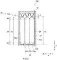
- FIG. 2 is a schematic longitudinal cross-sectional view taken along the line II-II in FIG. 1 .
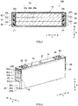
- FIG. 3 is a schematic longitudinal cross-sectional view taken along the line III-III in FIG. 1 .
- FIG. 4 is a schematic transverse cross-sectional view taken along the line IV-IV in FIG. 1 . Note that in the following description, symbols L, R, F, Rr, U, and D in the drawings show a left side, a right side, a front side, a rear side, an upper side, and a lower side, respectively.
- symbols X, Y, and Z in the drawings show a short side direction of the battery 100, a long side direction orthogonal to the short side direction, and a vertical direction, respectively.
- the long side direction is an example of a winding axis direction.
- these directions show directions only for the convenience of explanation and do not intend to limit the installation mode of the battery 100 at all.
- the battery 100 includes a battery case 10, an electrode body group 20, a positive electrode terminal 30, a negative electrode terminal 40, a positive electrode collecting part 50, a negative electrode collecting part 60, a positive electrode insulating member 70, and a negative electrode insulating member 80.
- the electrode body group 20 has winding electrode bodies 20a, 20b, and 20c (see FIG. 3 ).
- the positive electrode insulating member 70 has a base part 70a and a plurality of protrusion parts 70b.
- the negative electrode insulating member 80 has a base part 80a and a plurality of protrusion parts 80b.
- the protrusion parts 70b of the positive electrode insulating member 70 and the protrusion parts 80b of the negative electrode insulating member 80 are an example of spacers arranged between a sealing plate 14 and the winding electrode bodies 20a, 20b, and 20c.
- the battery 100 further includes an electrolytic solution here.
- the battery 100 is a lithium-ion secondary battery here.
- the battery 100 is characterized by including the winding electrode bodies 20a, 20b, and 20c, and the other configurations may be the same as those of conventional technologies.
- the battery case 10 is a housing that accommodates the electrode body group 20.
- the battery case 10 has a flat and bottomed cuboid (square) outer shape.
- the material of the battery case 10 may be the same as a conventionally-used one and is not particularly limited.
- the battery case 10 is preferably made of metal and more preferably made of, for example, aluminum, an aluminum alloy, iron, an iron alloy, or the like.
- the battery case 10 includes an exterior body 12 having an opening 12h and the sealing plate (lid body) 14 that seals the opening 12h.
- the exterior body 12 includes a bottom wall 12a, a pair of long side walls 12b extending from the bottom wall 12a and facing each other, and a pair of short side walls 12c extending from the bottom wall 12a and facing each other.
- the bottom wall 12a has a substantially rectangular shape.
- the bottom wall 12a faces the opening 12h.
- the areas of the short side walls 12c are smaller than those of the long side walls 12b.
- the long side walls 12b and the short side walls 12c are an example of first side walls and second side walls disclosed here.
- the sealing plate 14 is attached so as to seal the opening 12h of the exterior body 12.
- the sealing plate 14 faces the bottom wall 12a of the exterior body 12.
- the sealing plate 14 has a substantially rectangular shape in a plan view.
- the battery case 10 is integrated in such a manner that the sealing plate 14 is joined (for example, welding joint) to the peripheral edge of the opening 12h of the exterior body 12.
- the battery case 10 is air-tightly sealed.
- the sealing plate 14 is provided with a solution injection hole 15, a gas discharging valve 17, and two terminal withdrawing holes 18 and 19.
- the solution injection hole 15 is used to inject an electrolytic solution after the sealing plate 14 is attached to the exterior body 12.
- the solution injection hole 15 is sealed by the sealing member 16.
- the gas discharging valve 17 is configured to break and discharge gas inside the battery case 10 to an outside when the pressure inside the battery case 10 becomes a prescribed value or more.
- the terminal withdrawing holes 18 and 19 are formed at both ends in a long side direction Y of the sealing plate 14, respectively.
- the terminal withdrawing holes 18 and 19 penetrate the sealing plate 14 in the vertical direction Z.
- the terminal withdrawing holes 18 and 19 have respective inside diameters of a size at which the positive electrode terminal 30 and the negative electrode terminal 40 before being attached to the sealing plate 14 (before caulking work) are insertable.
- Each of the positive electrode terminal 30 and the negative electrode terminal 40 is fixed to the sealing plate 14.
- the positive electrode terminal 30 is arranged on one side (the left side in FIGS. 1 and 2 ) in the long side direction Y of the sealing plate 14.
- the negative electrode terminal 40 is arranged on the other side (the right side in FIGS. 1 and 2 ) in the long side direction Y of the sealing plate 14.
- the positive electrode terminal 30 and the negative electrode terminal 40 are exposed to the outside surface of the sealing plate 14.
- the positive electrode terminal 30 and the negative electrode terminal 40 are inserted into the terminal withdrawing holes 18 and 19, respectively, and extend from the inside to the outside of the sealing plate 14.
- the positive electrode terminal 30 and the negative electrode terminal 40 are caulked by caulking work at peripheral edge portions surrounding the terminal withdrawing holes 18 and 19 of the sealing plate 14.
- Caulking parts 30c and 40c are formed at ends (lower ends in FIG. 2 ) on the side of the exterior body 12 of the positive electrode terminal 30 and the negative electrode terminal 40.
- the positive electrode terminal 30 is electrically connected to a positive electrode 22 (see FIG. 7 ) of the electrode body group 20 via the positive electrode collecting part 50 inside the exterior body 12.
- the negative electrode terminal 40 is electrically connected to a negative electrode 24 (see FIG. 7 ) of the electrode body group 20 via the negative electrode collecting part 60 inside the exterior body 12.
- the positive electrode terminal 30 is insulated from the sealing plate 14 by the positive electrode insulating member 70 and a gasket 90.
- the negative electrode terminal 40 is insulated from the sealing plate 14 by the negative electrode insulating member 80 and a gasket 90.
- the positive electrode terminal 30 and the negative electrode terminal 40 are an example of terminals disclosed here.
- the positive electrode terminal 30 is preferably made of metal and more preferably made of, for example, aluminum or an aluminum alloy.
- the negative electrode terminal 40 is preferably made of metal and more preferably made of, for example, copper or a copper alloy.
- the negative electrode terminal 40 may be configured in such a manner that two conductive members are joined to and integrated with each other.
- a portion connected to the negative electrode collecting part 60 may be made of copper or a copper alloy, and a portion exposed to the outside surface of the sealing plate 14 may be made of aluminum or an aluminum alloy.
- a plate-shaped positive electrode outside conductive member 32 and a plate-shaped negative electrode outside conductive member 42 are attached to the outside surface of the sealing plate 14.
- the positive electrode outside conductive member 32 is electrically connected to the positive electrode terminal 30.
- the negative electrode outside conductive member 42 is electrically connected to the negative electrode terminal 40.
- the positive electrode outside conductive member 32 and the negative electrode outside conductive member 42 are members to which a bus bar is annexed when a plurality of batteries 100 are electrically connected to each other.
- the positive electrode outside conductive member 32 and the negative electrode outside conductive member 42 are preferably made of metal and more preferably made of, for example, aluminum or an aluminum alloy.
- the positive electrode outside conductive member 32 and the negative electrode outside conductive member 42 are insulated from the sealing plate 14 by outside insulating members 92.
- the positive electrode outside conductive member 32 and the negative electrode outside conductive member 42 are not necessarily provided and may be omitted in other embodiments.
- FIG. 5 is a perspective view schematically showing the electrode body group 20 attached to the sealing plate 14.
- the electrode body group 20 has the three winding electrode bodies 20a, 20b, and 20c.
- the number of winding electrode bodies arranged inside the one exterior body 12 is not particularly limited and may be two or more (plural number) or one.
- the electrode body group 20 is arranged inside the exterior body 12 in a state of being covered with an electrode body holder 29 (see FIG. 3 ) made of a resinous sheet.
- FIG. 6 is a perspective view schematically showing the winding electrode body 20a.
- the winding electrode body 20a is arranged inside the exterior body 12 with its winding axis WL directed parallel to the long side direction Y.
- the winding electrode body 20a is arranged inside the exterior body 12 with the winding axis WL directed parallel to the bottom wall 12a and orthogonal to the short side walls 12c.
- the end surfaces of the winding electrode body 20a (in other words, laminated surfaces where the positive electrode 22 and the negative electrode 24 are laminated with each other, end surfaces in the long side direction Y in FIG. 7 ) face the short side walls 12c.
- FIG. 7 is a schematic view showing the configuration of the winding electrode body 20a.
- the winding electrode body 20a has the positive electrode 22, the negative electrode 24, and a separator 26.
- the winding electrode body 20a is configured in such a manner that the strip-shaped positive electrode 22 and the strip-shaped negative electrode 24 are laminated with each other via the strip-shaped separator 26 and wound about the winding axis WL.
- the winding electrode body 20a has a flat shape.
- the positive electrode 22 has a positive electrode collector 22c and a positive electrode active material layer 22a and a positive electrode protection layer 22p that are fixed onto at least one surface of the positive electrode collector 22c.
- the positive electrode protection layer 22p is not necessarily provided and may be omitted in other embodiments.
- the positive electrode collector 22c has a strip shape.
- the positive electrode collector 22c is made of, for example, conductive metal such as aluminum, an aluminum alloy, nickel, and stainless steel.
- the positive electrode collector 22c is metal foil and specifically aluminum foil.
- a plurality of positive electrode tabs 22t are provided.
- the plurality of positive electrode tabs 22t protrude toward one side (the left side in FIG. 7 ) in the long side direction Y.
- the plurality of positive electrode tabs 22t protrude farther in the long side direction Y than the separator 26.
- the plurality of positive electrode tabs 22t are (intermittently) provided at intervals along the longitudinal direction of the positive electrode 22.
- the positive electrode tabs 22t are a part of the positive electrode collector 22c and made of metal foil (aluminum foil).
- each of the positive electrode tabs 22t has a trapezoidal shape.
- the positive electrode tabs 22t are portions (collector exposing parts) at which the positive electrode active material layer 22a and the positive electrode protection layer 22p of the positive electrode collector 22c are not formed.
- the positive electrode tabs 22t may be members different from the positive electrode collector 22c.
- the positive electrode tabs 22t may be provided at the other end (the right end in FIG. 7 ) in the long side direction Y, or may be provided at both respective ends in the long side direction Y.
- the plurality of positive electrode tabs 22t are laminated with each other at the one end (the left end in FIG. 4 ) in the long side direction Y and constitute a positive electrode tab group 23.
- the plurality of positive electrode tabs 22t are folded and curved so as to make their outward-side ends aligned with each other.
- the positive electrode tab group 23 is electrically connected to the positive electrode terminal 30 via the positive electrode collecting part 50.
- the plurality of positive electrode tabs 22t are preferably folded and electrically connected to the positive electrode terminal 30.
- a positive electrode second collecting part 52 that will be described later is annexed to the positive electrode tab group 23.
- the sizes (a length in the long side direction Y and a width orthogonal to the long side direction Y, see FIG.
- the sizes of the plurality of positive electrode tabs 22t are different from each other so that the outward-side ends are aligned with each other when curved.
- the positive electrode active material layer 22a is provided in a strip shape along the longitudinal direction of the strip-shaped positive electrode collector 22c.
- the positive electrode active material layer 22a contains a positive electrode active material (for example, a lithium transition metal composite oxide such as a lithium-nickel-cobalt-manganese composite oxide) capable of reversibly occluding and releasing a charge carrier.
- a positive electrode active material for example, a lithium transition metal composite oxide such as a lithium-nickel-cobalt-manganese composite oxide
- the positive electrode active material may generally account for 80 mass% or more, typically account for 90 mass% or more, and account for, for example, 95 mass% or more.
- the positive electrode active material layer 22a may contain an arbitrary component other than the positive electrode active material, such as a conductive material, a binder, and various additive components.
- a conductive material such as a carbon material such as acetylene black (AB) can be, for example, used.
- AB acetylene black
- the binder polyvinylidene fluoride (PVdF) can be, for example, used.
- the positive electrode protection layer 22p is provided at the boundary portion between the positive electrode collector 22c and the positive electrode active material layer 22a in the long side direction Y.
- the positive electrode protection layer 22p is provided at the one end (the left end in FIG. 7 ) in the long side direction Y of the positive electrode collector 22c.
- the positive electrode protection layer 22p may be provided at both ends in the long side direction Y.
- the positive electrode protection layer 22p is provided in a strip shape along the positive electrode active material layer 22a.
- the positive electrode protection layer 22p contains an inorganic filler (for example, alumina).
- the inorganic filler may generally account for 50 mass% or more, typically account for 70 mass% or more, and account for, for example, 80 mass% or more.
- the positive electrode protection layer 22p may contain an arbitrary component other than the inorganic filler, such as a conductive material, a binder, and various additive components.
- the conductive material and the binder may be the same as those that can be contained in the positive electrode active material layer 22a exemplified above.
- the negative electrode 24 has a negative electrode collector 24c and a negative electrode active material layer 24a that is fixed onto at least one surface of the negative electrode collector 24c.
- the negative electrode collector 24c has a strip shape.
- the negative electrode collector 24c is made of, for example, conductive metal such as copper, a copper alloy, nickel, and stainless steel.
- the negative electrode collector 24c is metal foil and specifically copper foil.
- a plurality of negative electrode tabs 24t are provided.
- the plurality of negative electrode tabs 24t protrude toward one side (the right side in FIG. 7 ) in the long side direction Y.
- the plurality of negative electrode tabs 24t protrude farther in the long side direction Y than the separator 26.
- the plurality of negative electrode tabs 24t are (intermittently) provided at intervals along the longitudinal direction of the negative electrode 24.
- the negative electrode tabs 24t are a part of the negative electrode collector 24c and made of metal foil (copper foil).
- each of the plurality of negative electrode tabs 24t has a trapezoidal shape.
- the negative electrode tabs 24t are portions (collector exposing parts) at which the negative electrode active material layer 24a of the negative electrode collector 24c is not formed.
- the negative electrode tabs 24t may be members different from the negative electrode collector 24c.
- the negative electrode tabs 24t may be provided at the other end (the right end in FIG. 7 ) in the long side direction Y, or may be provided at both respective ends in the long side direction Y.
- the plurality of negative electrode tabs 24t are laminated with each other at the one end (the right end in FIG. 6 ) in the long side direction Y and constitute a negative electrode tab group 25.
- the plurality of negative electrode tabs 24t are folded and curved so as to make their outward-side ends aligned with each other.
- the negative electrode tab group 25 is electrically connected to the negative electrode terminal 40 via the negative electrode collecting part 60.
- the plurality of negative electrode tabs 24t are preferably folded and electrically connected to the negative electrode terminal 40.
- a negative electrode second collecting part 62 that will be described later is annexed to the negative electrode tab group 25.
- the sizes (a length in the long side direction Y and a width orthogonal to the long side direction Y, see FIG.
- the sizes of the plurality of negative electrode tabs 24t are different from each other so that the outward-side ends are aligned with each other when curved.
- the negative electrode active material layer 24a is provided in a strip shape along the longitudinal direction of the strip-shaped negative electrode collector 24c.
- the negative electrode active material layer 24a contains a negative electrode active material (for example, a carbon material such as graphite) capable of reversibly occluding and releasing a charge carrier.
- a negative electrode active material for example, a carbon material such as graphite
- the negative electrode active material may generally account for 80 mass% or more, typically account for 90 mass% or more, and account for, for example, 95 mass% or more.
- the negative electrode active material layer 24a may contain an arbitrary component other than the negative electrode active material, such as a binder, a dispersing agent, and various additive components.
- the binder rubbers such as styrene butadiene rubber (SBR) can be, for example, used.
- SBR styrene butadiene rubber
- the dispersing agent celluloses such as carboxymethyl cellulose (CMC) can be,
- the separator 26 is a member that insulates the positive electrode active material layer 22a of the positive electrode 22 and the negative electrode active material layer 24a of the negative electrode 24 from each other.
- the separator 26 constitutes the outside surface of the winding electrode body 20a.
- a resinous porous sheet made of a polyolefin resin such as polyethylene (PE) and polypropylene (PP) is, for example, suitable.
- the separator 26 has a base material part made of a resinous porous sheet and a heat resistance layer (HRL) formed on at least one surface of the base material part.
- the heat resistance layer is typically a layer containing an inorganic filler and a binder.
- alumina, boehmite, aluminum hydroxide, titania, or the like can be, for example, used.
- binder polyvinylidene fluoride (PVdF) or the like can be, for example, used.
- the winding electrode body 20a has a pair of curvature parts (R parts) 20r that face the bottom wall 12a of the exterior body 12 and the sealing plate 14 and a flat part 20f that connects the pair of curvature parts 20r to each other and faces the long side walls 12b of the exterior body 12.
- one (an upper one in FIG. 3 ) of the curvature parts 20r indirectly faces the sealing plate 14 via a positive electrode first collecting part 51, a negative electrode first collecting part 61, the positive electrode insulating member 70, the negative electrode insulating member 80, or the like that will be described later.
- the other (a lower one in FIG. 3 ) of the curvature parts 20r indirectly faces the bottom wall 12a via the electrode body holder 29.
- the winding electrode body 20a will be described in detail below as an example, the winding electrode bodies 20b and 20c may have the same configuration.
- FIG. 8 is a partially-enlarged cross-sectional view schematically showing the vicinity of the upper end of the winding electrode body 20a in FIG. 3 .
- a line perpendicular to the winding axis WL of the winding electrode body 20a and perpendicular to the bottom wall 12a is indicated as a line L1.
- a line connecting the pair of apexes to each other is more preferably assumed as the line L1.
- a portion 24o positioned at the outermost peripheral part of the negative electrode 24 faces a portion 24i positioned on the winding inner peripheral side of the negative electrode 24 via the separator 26 on the line L1.
- the portion 24o positioned at the outermost peripheral part of the negative electrode 24 does not face the positive electrode 22.
- the curvature part 20r of the winding electrode body 20a is strongly pressed by the protrusion part 70b of the positive electrode insulating member 70 and the separator 26 is damaged in an insertion step that will be described later, it is possible to prevent the short circuit between the portion 24o positioned at the outermost peripheral part of the negative electrode 24 and the positive electrode 22 positioned on the winding inner peripheral side.
- the protrusion part 70b (spacer) of the positive electrode insulating member 70 that will be described later is particularly preferably positioned on the line L1.
- the portion closest to the protrusion part 70b of the positive electrode insulating member 70 crosses the line L1.
- the portion 24o positioned at the outermost peripheral part of the negative electrode 24 faces the portion 24i positioned on the winding inner peripheral side of the negative electrode 24 via the separator 26 on the line L1.
- the portion 24o positioned at the outermost peripheral part of the negative electrode 24 does not face the positive electrode 22.
- the winding electrode body 20a is not liable to move greatly toward the sealing plate 14. Therefore, it is possible to prevent damage on the separator 26 caused when the winding electrode body 20a contacts the sealing plate 14.
- a winding terminal 22e of the positive electrode 22 is arranged closer to an inner peripheral side than a winding terminal 24e of the negative electrode 24.
- the winding terminal 22e of the positive electrode 22 is preferably positioned at one of the curvature parts 20r.
- the winding terminal 22e of the positive electrode 22 is positioned at the curvature part 20r facing the sealing plate 14.
- the winding terminal 22e of the positive electrode 22 is arranged closer to the winding inner peripheral side than the line L1.
- a length from the winding terminal 22e of the positive electrode 22 to the line L1 is indicated as La.
- the length La is preferably 0.1 mm to 20 mm, more preferably 0.1 mm to 9 mm, and further more preferably 3 mm to 7 mm.
- the length La may be 5 mm or more.
- a winding terminal 24e of the negative electrode 24 is arranged closer to a winding outer peripheral side than a winding terminal 22e of the positive electrode 22.
- the winding terminal 24e of the negative electrode 24 is preferably positioned at one of the curvature parts 20r.
- the winding terminal 24e of the negative electrode 24 is positioned at the curvature part 20r facing the sealing plate 14.
- the winding terminal 24e of the negative electrode 24 is arranged closer to the winding outer peripheral side than the line L1 (in other words, a position over the line L1).
- a length from the line L1 to the winding terminal 24e of the negative electrode 24 is indicated as Lb.
- the length Lb is preferably 0.1 mm to 20 mm, more preferably 0.1 mm to 9 mm, and further more preferably 3 mm to 7 mm.
- the winding terminal 24e of the negative electrode 24 may be arranged on the line L1.
- the length Lb may be 0 mm.
- a length from the winding terminal 22e of the positive electrode 22 to the winding terminal 24e of the negative electrode 24 is indicated as La + Lb.
- the winding terminal 24e of the negative electrode 24 is arranged at a position ahead of the winding terminal 22e of the positive electrode 22 by the length La + Lb in the winding direction.
- the length La + Lb is preferably 0.1 mm or more, more preferably 0.1 mm to 18 mm, and further more preferably 6 mm to 14 mm.
- a winding terminal 26e of the separator 26 is arranged closer to the winding outer peripheral side than the winding terminal 22e of the positive electrode 22 and the winding terminal 24e of the negative electrode 24.
- the winding terminal 26e of the separator 26 is arranged at a position ahead of the winding terminal 24e of the negative electrode 24 in the winding direction.
- a fastening tape 28 is attached to the winding terminal 26e of the separator 26.
- the fastening tape 28 is arranged at the flat part 20f so that its whole area does not put on the curvature part 20r.
- the winding terminal 26e of the separator 26 is preferably positioned at the flat part 20f. With such a configuration, it is possible to effectively prevent a fluctuation in the thickness (the length in a short side direction X in FIG. 8 ) of the plurality of winding electrode bodies 20a, 20b, and 20c. As a result, it is possible to charge and discharge the plurality of winding electrode bodies 20a, 20b, and 20c in a balanced manner. Note that a part of the fastening tape 28 could be arranged at the flat part 20f depending on circumstances when the winding terminal 26e of the separator 26 is arranged at one of the curvature parts 20r, which possibly results in a fluctuation in the thickness of the winding electrode body 20a.
- the curvature part 20r facing the sealing plate 14 has a recessed part 20d.
- the recessed part 20d is formed when the winding electrode body 20a is pressed by the protrusion part 70b of the positive electrode insulating member 70 and/or the protrusion part 80b of the negative electrode insulating member 80.
- the recessed part 20d is formed between the winding terminal 22e of the positive electrode 22 and the winding terminal 24e of the negative electrode 24 (that is, within the range of the length La + Lb).
- the portion 24o positioned at the outermost peripheral part of the negative electrode 24 and the separator 26 are crushed so as to come close to the portion 24i positioned on the winding inner peripheral side of the negative electrode 24.
- the separator 26 has the heat resistance layer arranged closer to the side of the outside surface than the base material part on the outermost peripheries of the winding electrode bodies 20a, 20b, and 20c.
- the outside surfaces of the winding electrode bodies 20a, 20b, and 20c are covered with the heat resistance layer of the separator 26. Since the outside surfaces of the winding electrode bodies 20a, 20b, and 20c are covered with the heat resistance layer at least at one of the pair of curvature parts 20r, it is possible to relax stress applied to the curvature parts 20r even if the curvature parts 20r contact the bottom wall 12a and/or the sealing plate 14. Thus, the separator 26 is not liable to be damaged. Further, even if the separator 26 is damaged, it is possible to prevent the short circuit between the portion 24o positioned at the outermost peripheral part of the negative electrode 24 and the positive electrode 22 positioned on the winding inner peripheral side.
- the electrolytic solution may be a conventional type and is not particularly limited.
- the electrolytic solution is, for example, a nonaqueous electrolytic solution containing a nonaqueous system solvent and supporting salt.
- the nonaqueous system solvent contains, for example, carbonates such as ethylene carbonate, dimethyl carbonate, and ethyl methyl carbonate.
- the supporting salt is, for example, fluorine-containing lithium salt such as LiPF6.
- the electrolytic solution may be a solid state (solid electrolytic) and integrated with the electrode body group 20.
- the positive electrode collecting part 50 constitutes a conduction path that electrically connects the positive electrode tab group 23 including the plurality of positive electrode tabs 22t and the positive electrode terminal 30 to each other.
- the positive electrode collecting part 50 includes the positive electrode first collecting part 51 and the positive electrode second collecting part 52.
- the positive electrode first collecting part 51 and the positive electrode second collecting part 52 may be made of the same metal type as that of the positive electrode collector 22c, for example, conductive metal such as aluminum, an aluminum alloy, nickel, and stainless steel.
- FIG. 9 is a partially-enlarged cross-sectional view schematically showing the vicinity of the positive electrode terminal 30 in FIG. 2 .
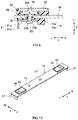
- FIG. 10 is a perspective view schematically showing the sealing plate 14.
- FIG. 11 is a perspective view in which the sealing plate in FIG. 10 is reversed.
- FIG. 11 shows the surface on the side (inside) of the exterior body 12 of the sealing plate 14.
- the positive electrode first collecting part 51 is attached to the inside surface of the sealing plate 14.
- the positive electrode first collecting part 51 is an example of a collecting part disclosed here.
- the positive electrode first collecting part 51 has a first region 51a and a second region 51b.
- the positive electrode first collecting part 51 may be configured in such a manner that one member is folded by, for example, press work or the like, or may be configured in such a manner that a plurality of members are integrated with each other by welding joint or the like.
- the positive electrode first collecting part 51 is fixed to the sealing plate 14 by caulking work.
- the first region 51a is a portion arranged between the sealing plate 14 and the electrode body group 20.
- the first region 51a extends along the long side direction Y.
- the first region 51a spreads horizontally along the inside surface of the sealing plate 14.
- the positive electrode insulating member 70 is arranged between the sealing plate 14 and the first region 51a.
- the first region 51a is insulated from the sealing plate 14 by the positive electrode insulating member 70.
- the first region 51a is electrically connected to the positive electrode terminal 30 by caulking work.
- a through-hole 51h penetrating in the vertical direction Z is formed at a position corresponding to the terminal withdrawing hole 18 of the sealing plate 14.
- the second region 51b is a portion arranged between the short side wall 12c of the exterior body 12 and the electrode body group 20.
- the second region 51b extends from one side end (the left end in FIG. 9 ) in the long side direction Y of the first region 51a to the short side wall 12c of the exterior body 12.
- the second region 51b extends along the vertical direction Z.
- the positive electrode second collecting part 52 extends along the short side wall 12c of the exterior body 12. As shown in FIG. 6 , the positive electrode second collecting part 52 has a collecting plate connection part 52a, an inclined part 52b, and a tab joining part 52c.
- the collecting plate connection part 52a is a portion electrically connected to the positive electrode first collecting part 51.
- the collecting plate connection part 52a extends along the vertical direction Z.
- the collecting plate connection part 52a is arranged substantially perpendicular to the winding axis WL of the winding electrode bodies 20a, 20b, and 20c.
- the collecting plate connection part 52a is provided with a recessed part 52d thinner than its periphery.
- the recessed part 52d is provided with a through-hole 52e penetrating in the short side direction X.
- the through-hole 52e has a joining part joined to the positive electrode first collecting part 51.
- the joining part is, for example, a weld joining part formed by welding such as ultrasonic wave welding, resistance welding, and laser welding.
- the positive electrode second collecting part 52 may be provided with a fuse.
- the tab joining part 52c is a portion annexed to the positive electrode tab group 23 and electrically connected to the plurality of positive electrode tabs 22t. As shown in FIG. 5 , the tab joining part 52c extends along the vertical direction Z. The tab joining part 52c is arranged substantially perpendicular to the winding axis WL of the winding electrode bodies 20a, 20b, and 20c. The surface of the tab joining part 52c that is connected to the plurality of positive electrode tabs 22t is arranged substantially parallel to the short side wall 12c of the exterior body 12. As shown in FIG. 4 , the tab joining part 52c has a joining part J joined to the positive electrode tab group 23.
- the joining part J is, for example, a welding joint part formed by welding such as ultrasonic wave welding, resistance welding, and laser welding in a state in which the plurality of positive electrode tabs 22t are overlapped with each other.
- the welding joint part is arranged with the plurality of positive electrode tabs 22t approaching one side in the short side direction X of the winding electrode bodies 20a, 20b, and 20c.
- the inclined part 52b is a portion that connects the lower end of the collecting plate connection part 52a and the upper end of the tab joining part 52c to each other.
- the inclined part 52b is inclined with respect to the collecting plate connection part 52a and the tab joining part 52c.
- the inclined part 52b connects the collecting plate connection part 52a and the tab joining part 52c to each other so that the collecting plate connection part 52a is positioned closer to a central side than the tab joining part 52c in the long side direction Y.
- the lower end (in other words, the end on the side of the bottom wall 12a of the exterior body 12) of the inclined part 52b is preferably positioned below the lower end of the positive electrode tab group 23.
- the negative electrode collecting part 60 constitutes a conduction path that electrically connects the negative electrode tab group 25 including the plurality of negative electrode tabs 24t and the negative electrode terminal 40 to each other.
- the negative electrode collecting part 60 includes the negative electrode first collecting part 61 and the negative electrode second collecting part 62.
- the negative electrode first collecting part 61 is an example of a collecting part disclosed here.
- the negative electrode first collecting part 61 and the negative electrode second collecting part 62 may be made of the same metal type as that of the negative electrode collector 24c, for example, conductive metal such as copper, a copper alloy, nickel, and stainless steel.
- the configurations of the negative electrode first collecting part 61 and the negative electrode second collecting part 62 may be the same as those of the positive electrode first collecting part 51 and the positive electrode second collecting part 52 of the positive electrode collecting part 50.
- the negative electrode first collecting part 61 has a first region 61a and a second region 61b.
- the negative electrode insulating member 80 is arranged between the sealing plate 14 and the first region 61a.
- the first region 61a is insulated from the sealing plate 14 by the negative electrode insulating member 80.
- a through-hole 61h penetrating in the vertical direction Z is formed at a position corresponding to the terminal withdrawing hole 19 of the sealing plate 14. As shown in FIG.
- the negative electrode second collecting part 62 has a collecting plate connection part 62a electrically connected to the negative electrode first collecting part 61, an inclined part 62b, and a tab joining part 62c that is annexed to the negative electrode tab group 25 and electrically connected to the plurality of negative electrode tabs 24t.
- the collecting plate connection part 62a has a recessed part 62d connected to the tab joining part 62c.
- the recessed part 62d is provided with a through-hole 62e penetrating in the short side direction X.
- the positive electrode insulating member 70 is a member that insulates the sealing plate 14 and the positive electrode first collecting part 51 from each other. Note that although the positive electrode insulating member 70 will be described in detail below as an example, the negative electrode insulating member 80 may have the same configuration.
- the positive electrode insulating member 70 preferably has resistance and electrical insulating properties with respect to a used electrolytic solution, made of an elastically-deformable resin material, and made of, for example, a polyolefin resin such as polypropylene (PP), a fluorinated resin such as tetrafluoroethylene-perfluoroalkoxyethylene copolymer (PFA), polyphenylene sulfide (PPS), or the like.
- a polyolefin resin such as polypropylene (PP)
- a fluorinated resin such as tetrafluoroethylene-perfluoroalkoxyethylene copolymer (PFA), polyphenylene sulfide (PPS), or
- the positive electrode insulating member 70 has the base part 70a and the plurality of protrusion parts 70b.
- the base part 70a and the protrusion parts 70b are integrally molded.
- the positive electrode insulating member 70 is an integrated molded article obtained by integrally molding resin materials as described above.
- the base part 70a and the protrusion parts 70b are members different from each other, it is possible to reduce the number of used members and realize cost reduction. Further, it is possible to more easily prepare the positive electrode insulating member 70.
- the base part 70a is a portion arranged between the sealing plate 14 and the first region 51a of the positive electrode first collecting part 51 in the vertical direction Z.
- the base part 70a spreads horizontally along the first region 51a of the positive electrode first collecting part 51.
- the base part 70a has a through-hole 70h penetrating in the vertical direction Z.
- the through-hole 70h is formed at a position corresponding to the terminal withdrawing hole 18 of the sealing plate 14.
- Each of the plurality of protrusion parts 70b protrudes closer to the side of the electrode body group 20 than the base part 70a.
- the plurality of protrusion parts 70b are provided closer to the central side (the right side in FIG. 11 ) of the sealing plate 14 than the base part 70a in the long side direction Y.
- the plurality of protrusion parts 70b are arranged side by side in the short side direction X.
- the plurality of protrusion parts 70b here face the curvature parts 20r of the winding electrode bodies 20a, 20b, and 20c constituting the electrode body group 20.
- the number of the protrusion parts 70b is the same as the number of the winding electrode bodies 20a, 20b, and 20c constituting the electrode body group 20, i.e., three.
- the winding electrode bodies 20a, 20b, and 20c and the protrusion parts 70b more reliably face each other and more effectively exhibit the effect of the technology disclosed here.
- the winding electrode bodies 20a, 20b, and 20c and the protrusion parts 70b contact each other in a balanced manner in the insertion step that will be described later.
- the number of the protrusion parts 70b may be different from the number of electrode bodies constituting the electrode body group 20, and may be, for example, one.
- the protrusion parts 70b are formed in a substantially U-shape in cross section.
- the protrusion parts 70b preferably protrude closer to the side of the electrode body group 20 than the surface on the side of the electrode body group 20 of the first region 51a.
- the protrusion parts 70b do not preferably contact the winding electrode bodies 20a, 20b, and 20c constituting the electrode body group 20.
- the plurality of protrusion parts 70b are preferably arranged at positions separated from the winding electrode bodies 20a, 20b, and 20c.
- a length Ha of the winding electrode body 20a is preferably smaller than a distance Hb from the lower ends of the protrusion parts 70b to the bottom wall 12a of the exterior body 12 (i.e., Ha ⁇ Hb).
- a distance Hb from the lower ends of the protrusion parts 70b to the bottom wall 12a of the exterior body 12 i.e., Ha ⁇ Hb.
- the shortest distance D between the protrusion parts 70b and the winding electrode bodies 20a, 20b, and 20c is preferably 5 mm or less, more preferably 3 mm or less, and further more preferably 2 mm or less.
- the protrusion parts 70b and the winding electrode bodies 20a, 20b, and 20c may contact each other in other embodiments.
- the area of a region 71 at the shortest distance D from the winding electrode body 20a in the protrusion part 70b is generally preferably 1% to 20%, more preferably 1% to 10%, and further more preferably 1% to 5% when it is assumed that the area of the winding electrode body 20a in a top view is 100%.
- the region 71 at the shortest distance D from the winding electrode body 20a has a flat surface on the side of the winding electrode bodies 20a, 20b, and 20c.
- the region 71 may have a shape along the outside surface (upper surface) of each of the winding electrode bodies 20a, 20b, and 20c, specifically a curved shape along the curvature part 20r.
- the negative electrode insulating member 80 is arranged symmetrically with the positive electrode insulating member 70 with respect to a center CL in the long side direction Y of the electrode body group 20.
- the configuration of the negative electrode insulating member 80 may be the same as that of the positive electrode insulating member 70.
- the negative electrode insulating member 80 has the base part 80a arranged between the sealing plate 14 and the negative electrode first collecting part 61 and the plurality of protrusion parts 80b like the positive electrode insulating member 70.
- the battery 100 preferably includes both the positive electrode insulating member 70 and the negative electrode insulating member 80.
- the electrode body group 20 and the sealing plate 14 are easily maintained in a parallel state (a state in FIG. 2 ). Further, in the insertion step that will be described later, it is possible to make the electrode body group 20 and the protrusion parts 70b contact each other more suitably (for example, in a balanced manner in the long side direction Y) and stably press the electrode body group 20 by the protrusion parts 70b to be inserted into the exterior body 12.
- a manufacturing method for the battery 100 is characterized by using the winding electrode bodies 20a, 20b, and 20c as described above. Other manufacturing processes may be the same as those of conventional technologies.
- the battery 100 may be manufactured by a manufacturing method in which the battery case 10 (the exterior body 12 and the sealing plate 14), the electrode body group 20 (the winding electrode bodies 20a, 20b, and 20c), the electrolytic solution, the positive electrode terminal 30, the negative electrode terminal 40, the positive electrode collecting part 50 (the positive electrode first collecting part 51 and the positive electrode second collecting part 52), and the negative electrode collecting part 60 (the negative electrode first collecting part 61 and the negative electrode second collecting part 62) as described above are prepared in addition to the positive electrode insulating member 70 and the negative electrode insulating member 80, and which includes, for example, a first attachment step, a second attachment step, an insertion step, and a sealing step in this order. Further, the manufacturing method disclosed here may further include other steps in arbitrary stages.
- a first united object as shown in FIGS. 10 and 11 is manufactured. Specifically, the positive electrode terminal 30, the positive electrode first collecting part 51, the positive electrode insulating member 70, the negative electrode terminal 40, the negative electrode first collecting part 61, and the negative electrode insulating member 80 are first attached to the sealing plate 14.
- the positive electrode terminal 30, the positive electrode first collecting part 51, and the positive electrode insulating member 70 are fixed to the sealing plate 14 by, for example, caulking work (riveting). As shown in FIG. 9 , the caulking work is performed with the gasket 90 held between the outside surface of the sealing plate 14 and the positive electrode terminal 30 and also with the positive electrode insulating member 70 held between the inside surface of the sealing plate 14 and the positive electrode first collecting part 51. Note that the material of the gasket 90 may be the same as that of the positive electrode insulating member 70.
- the positive electrode terminal 30 before the caulking work is inserted into a through-hole 90h of the gasket 90, the terminal withdrawing hole 18 of the sealing plate 14, the through-hole 70h of the positive electrode insulating member 70, and the through-hole 51h of the positive electrode first collecting part 51 in order from above the sealing plate 14 and caused to protrude below the sealing plate 14. Then, the portion of the positive electrode terminal 30 protruding below the sealing plate 14 is caulked so that a compressive force is applied in the vertical direction Z. Thus, a caulking part 30c is formed at the tip end (the lower end in FIG. 2 ) of the positive electrode terminal 30.
- the gasket 90, the sealing plate 14, the positive electrode insulating member 70, and the positive electrode first collecting part 51 are integrally fixed to the sealing plate 14 and the terminal withdrawing hole 18 is sealed.
- the caulking part 30c may be welded and joined to the positive electrode first collecting part 51. Thus, it is possible to further improve conduction reliability.
- the fixation between the negative electrode terminal 40, the negative electrode first collecting part 61, and the negative electrode insulating member 80 may be performed like the case of the positive electrode described above. That is, the negative electrode terminal 40 before caulking work is inserted into the through-hole of a gasket, the terminal withdrawing hole 19 of the sealing plate 14, the through-hole of the negative electrode insulating member 80, and the through-hole of the negative electrode first collecting part 61 in order from above the sealing plate 14 and caused to protrude below the sealing plate 14. Then, the portion of the negative electrode terminal 40 protruding below the sealing plate 14 is caulked so that a compressive force is applied in the vertical direction Z. Thus, a caulking part 40c is formed at the tip end (the lower end in FIG. 2 ) of the negative electrode terminal 40.
- a positive electrode outside conductive member 32 and a negative electrode outside conductive member 42 are attached to the outside surface of the sealing plate 14 via the outside insulating members 92.
- the material of the outside insulating members 92 may be the same as that of the positive electrode insulating member 70.
- a timing at which the positive electrode outside conductive member 32 and the negative electrode outside conductive member 42 are attached may be set after the insertion step (for example, after the solution injection hole 15 is sealed).
- a second united object as shown in FIG. 5 is manufactured using the first united object manufactured in the first attachment step.
- three winding electrode bodies 20a to which the positive electrode second collecting part 52 and the negative electrode second collecting part 62 are annexed as shown in FIG. 6 are first prepared and arranged side by side in the short side direction X as the winding electrode bodies 20a, 20b, and 20c.
- the winding electrode bodies 20a, 20b, and 20c may be arranged in parallel so that the positive electrode second collecting part 52 is arranged on one side (the left side in FIG. 5 ) in the long side direction Y and the negative electrode second collecting part 62 is arranged on the other side (the right side in FIG. 5 ) in the long side direction Y.
- the positive electrode first collecting part 51 (specifically, the second region 51b) fixed to the sealing plate 14 and the positive electrode second collecting part 52 (specifically, the collecting plate connection part 52a) of the winding electrode bodies 20a, 20b, and 20c are joined to each other.
- the negative electrode first collecting part 61 fixed to the sealing plate 14 and the negative electrode second collecting part 62 of the winding electrode bodies 20a, 20b, and 20c are joined to each other.
- welding such as ultrasonic wave welding, resistance welding, and laser welding may be used.
- welding by the irradiation of high-energy rays such as laser beams is preferably used.
- a joining part is formed on each of the recessed part 52d of the positive electrode second collecting part 52 and the recessed part 62d of the negative electrode second collecting part 62.
- FIG. 12 is a schematic cross-sectional view for describing the insertion step.
- an insulative resin sheet made of a resin material such as polyethylene (PE) is, for example, first folded in a bag shape or a box shape to prepare the electrode body holder 29.
- the electrode body group 20 is accommodated in the electrode body holder 29.
- the electrode body group 20 covered with the electrode body holder 29 is inserted into the exterior body 12.
- the electrode body group 20 When the weight of the electrode body group 20 is heavy, i.e, when the electrode body group 20 generally weighs 1 kg or more, weighs, for example, 1.5 kg or more, or weighs 2 kg to 3 kg, the electrode body group 20 may be inserted into the exterior body 12 (with the exterior body 12 turned sideways) so that the long side walls 12b of the exterior body 12 cross a gravity direction as shown in FIG. 12 .
- Each of the curvature parts 20r of the winding electrode bodies 20a, 20b, and 20c constituting the electrode body group 20 is pressed by the protrusion parts 70b of the positive electrode insulating member 70 and/or the protrusion parts 80b of the negative electrode insulating member 80 that serve as spacers and pressed into the exterior body 12.
- the protrusion parts 70b and/or the protrusion parts 80b By pressing the electrode body group 20 by the protrusion parts 70b and/or the protrusion parts 80b, it is possible to reduce loads on the positive electrode tab group 23 and/or the negative electrode tab group 25.
- the protrusion parts 70b and/or the protrusion parts 80b that serve as spacers can function as buffering members that reduce loads on the positive electrode tab group 23 and/or the negative electrode tab group 25.
- the protrusion parts 70b and/or the protrusion parts 80b preferably thrust the winding electrode bodies 20a, 20b, and 20c in a state of getting in the curvature parts 20r on one side of the winding electrode bodies 20a, 20b, and 20c.
- the positive electrode insulating member 70 and/or the negative electrode insulating member 80 tightly contact the winding electrode bodies 20a, 20b, and 20c and prevent the positive electrode insulating member 70 and/or the negative electrode insulating member 80 from sliding against the winding electrode bodies 20a, 20b, and 20c.
- the recessed parts 20d are formed at the portions of the winding electrode bodies 20a, 20b, and 20c that face the protrusion parts 70b and/or the protrusion parts 80b.
- the positive electrode tab group 23 and/or the negative electrode tab group 25 have play so as to be movable in a direction crossing their protruding direction. Therefore, when the exterior body 12 is raised so as to make the sealing plate 14 positioned on an upper side after the electrode body group 20 is inserted into the exterior body 12, the electrode body group 20 slightly moves downward due to its own weight.
- the protrusion parts 70b of the positive electrode insulating member 70 and the winding electrode bodies 20a, 20b, and 20c are arranged at separated positions.
- the protrusion parts 80b of the negative electrode insulating member 80 and the winding electrode bodies 20a, 20b, and 20c are arranged at separated positions.
- the sealing plate 14 is joined to the edge part of the opening 12h of the exterior body 12 to seal the opening 12h.
- the joining of the sealing plate 14 may be performed by, for example, welding such as laser welding.
- an electrolytic solution is injected from the solution injection hole 15, and the solution injection hole 15 is sealed by the sealing member 16 to tightly close the battery 100.
- the battery 100 is available for various applications but may be suitably used in an application in which an external force such as vibration and shock can be applied during use.
- the battery 100 may be suitably used as a power source (driving power) for a motor mounted in a mobile body (typically, a vehicle such as an automobile and a truck).
- a mobile body typically, a vehicle such as an automobile and a truck.
- the type of the vehicle is not particularly limited but examples of the vehicle include a plug-in hybrid vehicle (PHV), a hybrid vehicle (HV), and an electric vehicle (EV).
- the battery 100 may be suitably used as a battery pack in which a plurality of the batteries 100 are arranged in a prescribed array direction and a load is added by a constraint mechanism in the array direction.
- the protrusion parts 70b of the positive electrode insulating member 70 and/or the protrusion parts 80b of the negative electrode insulating member 80, and the winding electrode bodies 20a, 20b, and 20c do not preferably contact each other.
- the winding terminal 24e of the negative electrode 24 is arranged at the curvature part 20r of the winding electrode body 20a.
- the winding terminal 24e of the negative electrode 24 may be arranged at other places.
- the winding terminal 24e of the negative electrode 24 may be arranged at the flat part 20f.
- the positive electrode insulating member 70 includes the plurality of protrusion parts 70b, and each of the protrusion parts 70b has a substantially U-shaped cross section.
- the number of the protrusion parts 70b may be one.
- the protrusion parts 70b may have an arbitrary shape.
- the protrusion parts 70b may have, for example, a rectangular cross section.
- the protrusion parts 70b may have a rectangular part having a rectangular shape and one or a plurality of protrusion rib parts protruding to the side of the winding electrode bodies 20a, 20b, and 20c from the rectangular part.
- the protrusion parts 70b may have a square-shaped or U-shaped cross section.
Landscapes
- Chemical & Material Sciences (AREA)
- Chemical Kinetics & Catalysis (AREA)
- Electrochemistry (AREA)
- General Chemical & Material Sciences (AREA)
- Engineering & Computer Science (AREA)
- Manufacturing & Machinery (AREA)
- Materials Engineering (AREA)
- Inorganic Chemistry (AREA)
- Composite Materials (AREA)
- Secondary Cells (AREA)
- Connection Of Batteries Or Terminals (AREA)
- Electric Double-Layer Capacitors Or The Like (AREA)
- Cell Separators (AREA)
Abstract

Description
- The present teaching relates to a battery and a manufacturing method therefor.
- Conventionally, a battery including a winding electrode body in which a strip-shaped positive electrode including a positive electrode active material layer on a positive electrode collector and a strip-shaped negative electrode including a negative electrode active material layer on a negative electrode collector are laminated with each other via a strip-shaped separator and wound about a winding axis has been known (see
Japanese Patent Application Laid-open No. 2017-010878 Japanese Patent No. 5100441 - According to studies by the present inventors, a plurality of tabs have play so as to be movable in a direction crossing a direction protruding from a collector. Therefore, if vibration, shock, or the like is applied from an outside during the use of a battery or the like, a winding electrode body may contact a battery case or a component attached to the battery case. As a result, there is a possibility that a separator covering the outside surface of the winding electrode body is damaged and a positive electrode and a negative electrode are short-circuited to each other.
- The present teaching has been made in view of the above circumstances and has an object of providing a battery that prevents the short circuit between a positive electrode and a negative electrode and improves reliability and a manufacturing method for the battery.
- According to the present teaching, there is provided a battery including: an exterior body having a bottom wall, a pair of first side walls extending from the bottom wall and facing each other, a pair of second side walls extending from the bottom wall and facing each other, and an opening facing the bottom wall; a sealing plate that seals the opening of the exterior body; at least one winding electrode body in which a strip-shaped positive electrode and a strip-shaped negative electrode are laminated with each other via a strip-shaped separator and wound about a winding axis; a positive electrode tab group that includes a plurality of positive electrode tabs provided at an end in a winding axis direction of the winding electrode body and is electrically connected to the positive electrode; and a negative electrode tab group that includes a plurality of negative electrode tabs provided at an end in the winding axis direction of the winding electrode body and is electrically connected to the negative electrode. The winding electrode body has a flat shape having a pair of curvature parts having a curved outside surface and a flat part that connects the pair of curvature parts to each other and has a flat outside surface and is accommodated in the exterior body so that one of the curvature parts faces the sealing plate and the other thereof faces the bottom wall of the exterior body. Wherein, when a line perpendicular to the winding axis of the winding electrode body and perpendicular to the bottom wall is assumed as L1, a portion positioned at an outermost periphery of the negative electrode in at least one of the pair of the curvature parts faces a portion positioned on a winding inner peripheral side of the negative electrode via the separator and not via the positive electrode on the line L1.
- The winding electrode body of the battery is accommodated in the exterior body so that the curvature parts face the bottom wall of the exterior body and/or the sealing plate, and the portion positioned at the outermost periphery of the negative electrode in the curvature parts facing the bottom wall of the exterior body and/or the sealing plate faces the portion positioned on the winding inner peripheral side not via the positive electrode on the line L1. Thus, even if the curvature parts contact the bottom wall and/or the sealing plate and components provided in the bottom wall and the sealing plate to cause damage on the separator, it is possible to prevent the short circuit between the portion positioned at the outermost periphery of the negative electrode and the positive electrode. Accordingly, it is possible to improve the reliability of the battery.
- In a preferred mode of the battery disclosed here, the battery includes a spacer arranged between the sealing plate and the winding electrode body, and the portion positioned at the outermost periphery of the negative electrode faces the portion positioned on the winding inner peripheral side of the negative electrode via the separator and not via the positive electrode on the line L1. With such a configuration, the winding electrode body is not liable to move greatly toward the sealing plate. Therefore, it is possible to prevent damage on the separator caused when the winding electrode body contacts the sealing plate. Thus, it is possible to effectively prevent the short circuit between the positive electrode and the negative electrode. Further, it is possible to reduce loads on the positive electrode tab group and/or the negative electrode tab group and stably maintain electrical connection. Thus, it is possible to improve the conduction reliability of the battery.
- In a preferred mode of the battery disclosed here, the battery includes: a terminal that is attached to the sealing plate and electrically connected to the positive electrode tab group or the negative electrode tab group; a collecting part that electrically connects the positive electrode tab group or the negative electrode tab group and the terminal to each other; and an insulating member that insulates the sealing plate and the collecting part from each other and has a protrusion part protruding to a side of the winding electrode body from a side of the sealing plate, and the protrusion part of the insulating member constitutes the spacer. With such a configuration, it is possible to relax stress applied to the curvature parts even if the curvature parts contact the bottom wall and/or the sealing plate. Thus, the separator is not liable to be damaged, which makes it possible to effectively prevent the short circuit between the positive electrode and the negative electrode.
- In a preferred mode of the battery disclosed here, the spacer does not contact the winding electrode body. Thus, when the spacer is arranged at a position separated from the electrode body, it is possible to prevent the curvature parts and the spacer from rubbing against each other even if the winding electrode body moves toward the sealing plate. Thus, the separator is not liable to be damaged, which makes it possible to effectively prevent the short circuit between the positive electrode and the negative electrode.
- In a preferred mode of the battery disclosed here, the at least one winding electrode body includes a plurality of winding electrode bodies. In a battery including a plurality of winding electrode bodies, it is especially demanded that the short circuit between a positive electrode and a negative electrode be prevented to increase reliability. Accordingly, the application of the technology disclosed here is particularly effective.
- In a preferred mode of the battery disclosed here, the separator includes a resinous base material part and a heat resistance layer that is provided on the base material part and contains an inorganic filler, and the outside surface of the winding electrode body is covered with the heat resistance layer in at least one of the pair of curvature parts. With such a configuration, it is possible to relax stress applied to the curvature parts even if the curvature parts contact the bottom wall and/or the sealing plate. Thus, the separator is not liable to be damaged, which makes it possible to effectively prevent the short circuit between the positive electrode and the negative electrode.
- Further, according to the present teaching, there is provided a manufacturing method for a battery including an exterior body having a bottom wall, a pair of first side walls extending from the bottom wall and facing each other, a pair of second side walls extending from the bottom wall and facing each other, and an opening facing the bottom wall, a sealing plate that seals the opening of the exterior body, at least one winding electrode body in which a strip-shaped positive electrode and a strip-shaped negative electrode are laminated with each other via a strip-shaped separator and wound about a winding axis, a positive electrode tab group that includes a plurality of positive electrode tabs provided at an end in a winding axis direction of the winding electrode body and is electrically connected to the positive electrode, a negative electrode tab group that includes a plurality of negative electrode tabs provided at an end in the winding axis direction of the winding electrode body and is electrically connected to the negative electrode, and a spacer arranged between the sealing plate and the winding electrode body, the winding electrode body having a flat shape having a pair of curvature parts having a curved outside surface and a flat part that connects the pair of curvature parts to each other and has a flat outside surface and being accommodated in the exterior body so that one of the curvature parts faces the sealing plate and the other thereof faces the bottom wall of the exterior body. The manufacturing method includes: an insertion step of thrusting the winding electrode body into the exterior body with the spacer; and a sealing step of sealing the opening of the exterior body with the sealing plate. In the insertion step, a portion positioned at an outermost periphery of the negative electrode in at least a part of a region pressed by the spacer in the winding electrode body faces a portion positioned on a winding inner peripheral side of the negative electrode via the separator and not via the positive electrode.
- In the manufacturing method, the winding electrode body is thrusted into the exterior body when the curvature parts of the winding electrode body are pressed by the spacer. At this time, the portion positioned at the outermost periphery of the negative electrode is caused to face the portion positioned on the winding inner peripheral side of the negative electrode via the separator and not via the positive electrode, which makes it possible to prevent the short circuit between the portion positioned at the outermost periphery of the negative electrode and the positive electrode even if the curvature parts are strongly pressed by the spacer. Further, the winding electrode body is caused to contact the sealing plate or a component attached to the sealing plate by the spacer, which makes it possible to prevent damage on the separator. Accordingly, it is possible to stably insert the winding electrode body into the exterior body and manufacture the battery.
- When a line perpendicular to the winding axis of the winding electrode body and perpendicular to the bottom wall is assumed as L1, at least an outside surface positioned on the line L1 in the winding electrode body is pressed in the insertion step. Thus, it is possible to stably insert the winding electrode body into the exterior body, while preventing damage on the separator.
- In a preferred mode of the manufacturing method disclosed here, the spacer does not contact the winding electrode body after the sealing step. Thus, it is possible to prevent damage on the separator caused when the curvature parts and the spacer rub against each other even if the winding electrode body moves toward the sealing plate.
- In a preferred mode of the manufacturing method disclosed here, a shortest distance between the winding electrode body and the spacer is 5 mm or less after the sealing step. Thus, it is possible to make the electrode body and the spacer contact each other more suitably when thrusting the electrode body and more stably insert the electrode body into the exterior body.
-
-
FIG. 1 is a perspective view schematically showing a battery according to an embodiment; -
FIG. 2 is a schematic longitudinal cross-sectional view taken along the line II-II inFIG. 1 ; -
FIG. 3 is a schematic longitudinal cross-sectional view taken along the line III-III inFIG. 1 ; -
FIG. 4 is a schematic transverse cross-sectional view taken along the line IV-IV inFIG. 1 ; -
FIG. 5 is a perspective view schematically showing an electrode body group attached to a sealing plate; -
FIG. 6 is a perspective view schematically showing an electrode body to which a positive electrode second collecting part and a negative electrode second collecting part are attached; -
FIG. 7 is a schematic view showing the configuration of the winding electrode body; -
FIG. 8 is a partially-enlarged cross-sectional view schematically showing the vicinity of the upper end of the winding electrode body inFIG. 3 ; -
FIG. 9 is a partially-enlarged cross-sectional view schematically showing the vicinity of a positive electrode terminal inFIG. 2 ; -
FIG. 10 is a perspective view schematically showing the sealing plate in which the positive electrode terminal, a negative electrode terminal, a positive electrode first collecting part, a negative electrode first collecting part, a positive electrode insulating member, and a negative electrode insulating member are attached; -
FIG. 11 is a perspective view in which the sealing plate inFIG. 10 is reversed; and -
FIG. 12 is a schematic cross-sectional view for describing a battery insertion step according to an embodiment. - Hereinafter, some preferred embodiments of a technology disclosed here will be described with reference to the drawings. Note that matters other than those mentioned particularly in the present specification and necessary for the implementation of the present invention (for example, a general configuration and a manufacturing process of a battery not characterizing the present invention) can be grasped as design matters for skilled persons based on conventional technologies in the field concerned. The technology disclosed here may be implemented on the basis of contents disclosed in the present specification and technological common knowledge in the field concerned.
- In the present specification, a "battery" is a term indicating a general storage device from which electric energy is capable of being taken out and is a concept including a primary battery and a secondary battery. Further, in the present specification, a "secondary battery" is a term indicating a general storage device capable of performing repetitive charge and discharge and is a concept including a so-called storage battery (chemical cell) such as a lithium-ion secondary battery and a nickel hydrogen battery and a capacitor (physical cell) such as an electric double layer capacitor.
-
FIG. 1 is a perspective view of abattery 100.FIG. 2 is a schematic longitudinal cross-sectional view taken along the line II-II inFIG. 1 .FIG. 3 is a schematic longitudinal cross-sectional view taken along the line III-III inFIG. 1 .FIG. 4 is a schematic transverse cross-sectional view taken along the line IV-IV inFIG. 1 . Note that in the following description, symbols L, R, F, Rr, U, and D in the drawings show a left side, a right side, a front side, a rear side, an upper side, and a lower side, respectively. Further, symbols X, Y, and Z in the drawings show a short side direction of thebattery 100, a long side direction orthogonal to the short side direction, and a vertical direction, respectively. The long side direction is an example of a winding axis direction. However, these directions show directions only for the convenience of explanation and do not intend to limit the installation mode of thebattery 100 at all. - As shown in
FIG. 2 , thebattery 100 includes abattery case 10, anelectrode body group 20, apositive electrode terminal 30, anegative electrode terminal 40, a positiveelectrode collecting part 50, a negativeelectrode collecting part 60, a positiveelectrode insulating member 70, and a negativeelectrode insulating member 80. As will be described in detail later, theelectrode body group 20 has windingelectrode bodies FIG. 3 ). The positiveelectrode insulating member 70 has abase part 70a and a plurality ofprotrusion parts 70b. The negativeelectrode insulating member 80 has abase part 80a and a plurality ofprotrusion parts 80b. Theprotrusion parts 70b of the positiveelectrode insulating member 70 and theprotrusion parts 80b of the negativeelectrode insulating member 80 are an example of spacers arranged between a sealingplate 14 and the windingelectrode bodies battery 100 further includes an electrolytic solution here. Thebattery 100 is a lithium-ion secondary battery here. Thebattery 100 is characterized by including the windingelectrode bodies - The
battery case 10 is a housing that accommodates theelectrode body group 20. Thebattery case 10 has a flat and bottomed cuboid (square) outer shape. The material of thebattery case 10 may be the same as a conventionally-used one and is not particularly limited. Thebattery case 10 is preferably made of metal and more preferably made of, for example, aluminum, an aluminum alloy, iron, an iron alloy, or the like. As shown inFIG. 2 , thebattery case 10 includes anexterior body 12 having anopening 12h and the sealing plate (lid body) 14 that seals theopening 12h. - As shown in
FIG. 1 , theexterior body 12 includes abottom wall 12a, a pair oflong side walls 12b extending from thebottom wall 12a and facing each other, and a pair ofshort side walls 12c extending from thebottom wall 12a and facing each other. Thebottom wall 12a has a substantially rectangular shape. Thebottom wall 12a faces theopening 12h. The areas of theshort side walls 12c are smaller than those of thelong side walls 12b. Thelong side walls 12b and theshort side walls 12c are an example of first side walls and second side walls disclosed here. The sealingplate 14 is attached so as to seal theopening 12h of theexterior body 12. The sealingplate 14 faces thebottom wall 12a of theexterior body 12. The sealingplate 14 has a substantially rectangular shape in a plan view. Thebattery case 10 is integrated in such a manner that the sealingplate 14 is joined (for example, welding joint) to the peripheral edge of theopening 12h of theexterior body 12. Thebattery case 10 is air-tightly sealed. - As shown in
FIG. 2 , the sealingplate 14 is provided with asolution injection hole 15, agas discharging valve 17, and two terminal withdrawingholes solution injection hole 15 is used to inject an electrolytic solution after the sealingplate 14 is attached to theexterior body 12. Thesolution injection hole 15 is sealed by the sealingmember 16. Thegas discharging valve 17 is configured to break and discharge gas inside thebattery case 10 to an outside when the pressure inside thebattery case 10 becomes a prescribed value or more. Theterminal withdrawing holes plate 14, respectively. Theterminal withdrawing holes plate 14 in the vertical direction Z. Theterminal withdrawing holes positive electrode terminal 30 and thenegative electrode terminal 40 before being attached to the sealing plate 14 (before caulking work) are insertable. - Each of the
positive electrode terminal 30 and thenegative electrode terminal 40 is fixed to the sealingplate 14. Thepositive electrode terminal 30 is arranged on one side (the left side inFIGS. 1 and2 ) in the long side direction Y of the sealingplate 14. Thenegative electrode terminal 40 is arranged on the other side (the right side inFIGS. 1 and2 ) in the long side direction Y of the sealingplate 14. As shown inFIG. 1 , thepositive electrode terminal 30 and thenegative electrode terminal 40 are exposed to the outside surface of the sealingplate 14. As shown inFIG. 2 , thepositive electrode terminal 30 and thenegative electrode terminal 40 are inserted into theterminal withdrawing holes plate 14. Here, thepositive electrode terminal 30 and thenegative electrode terminal 40 are caulked by caulking work at peripheral edge portions surrounding theterminal withdrawing holes plate 14.Caulking parts FIG. 2 ) on the side of theexterior body 12 of thepositive electrode terminal 30 and thenegative electrode terminal 40. - As shown in
FIG. 2 , thepositive electrode terminal 30 is electrically connected to a positive electrode 22 (seeFIG. 7 ) of theelectrode body group 20 via the positiveelectrode collecting part 50 inside theexterior body 12. Thenegative electrode terminal 40 is electrically connected to a negative electrode 24 (seeFIG. 7 ) of theelectrode body group 20 via the negativeelectrode collecting part 60 inside theexterior body 12. Thepositive electrode terminal 30 is insulated from the sealingplate 14 by the positiveelectrode insulating member 70 and agasket 90. Thenegative electrode terminal 40 is insulated from the sealingplate 14 by the negativeelectrode insulating member 80 and agasket 90. Thepositive electrode terminal 30 and thenegative electrode terminal 40 are an example of terminals disclosed here. - The
positive electrode terminal 30 is preferably made of metal and more preferably made of, for example, aluminum or an aluminum alloy. Thenegative electrode terminal 40 is preferably made of metal and more preferably made of, for example, copper or a copper alloy. Thenegative electrode terminal 40 may be configured in such a manner that two conductive members are joined to and integrated with each other. For example, a portion connected to the negativeelectrode collecting part 60 may be made of copper or a copper alloy, and a portion exposed to the outside surface of the sealingplate 14 may be made of aluminum or an aluminum alloy. - As shown in
FIG. 1 , a plate-shaped positive electrode outsideconductive member 32 and a plate-shaped negative electrode outsideconductive member 42 are attached to the outside surface of the sealingplate 14. The positive electrode outsideconductive member 32 is electrically connected to thepositive electrode terminal 30. The negative electrode outsideconductive member 42 is electrically connected to thenegative electrode terminal 40. The positive electrode outsideconductive member 32 and the negative electrode outsideconductive member 42 are members to which a bus bar is annexed when a plurality ofbatteries 100 are electrically connected to each other. The positive electrode outsideconductive member 32 and the negative electrode outsideconductive member 42 are preferably made of metal and more preferably made of, for example, aluminum or an aluminum alloy. The positive electrode outsideconductive member 32 and the negative electrode outsideconductive member 42 are insulated from the sealingplate 14 by outside insulatingmembers 92. However, the positive electrode outsideconductive member 32 and the negative electrode outsideconductive member 42 are not necessarily provided and may be omitted in other embodiments. -
FIG. 5 is a perspective view schematically showing theelectrode body group 20 attached to the sealingplate 14. Here, theelectrode body group 20 has the three windingelectrode bodies exterior body 12 is not particularly limited and may be two or more (plural number) or one. Theelectrode body group 20 is arranged inside theexterior body 12 in a state of being covered with an electrode body holder 29 (seeFIG. 3 ) made of a resinous sheet. -
FIG. 6 is a perspective view schematically showing the windingelectrode body 20a. The windingelectrode body 20a is arranged inside theexterior body 12 with its winding axis WL directed parallel to the long side direction Y. In other words, the windingelectrode body 20a is arranged inside theexterior body 12 with the winding axis WL directed parallel to thebottom wall 12a and orthogonal to theshort side walls 12c. The end surfaces of the windingelectrode body 20a (in other words, laminated surfaces where thepositive electrode 22 and thenegative electrode 24 are laminated with each other, end surfaces in the long side direction Y inFIG. 7 ) face theshort side walls 12c. -
FIG. 7 is a schematic view showing the configuration of the windingelectrode body 20a. The windingelectrode body 20a has thepositive electrode 22, thenegative electrode 24, and aseparator 26. Here, the windingelectrode body 20a is configured in such a manner that the strip-shapedpositive electrode 22 and the strip-shapednegative electrode 24 are laminated with each other via the strip-shapedseparator 26 and wound about the winding axis WL. The windingelectrode body 20a has a flat shape. - As shown in
FIG. 7 , thepositive electrode 22 has apositive electrode collector 22c and a positive electrodeactive material layer 22a and a positiveelectrode protection layer 22p that are fixed onto at least one surface of thepositive electrode collector 22c. However, the positiveelectrode protection layer 22p is not necessarily provided and may be omitted in other embodiments. Thepositive electrode collector 22c has a strip shape. Thepositive electrode collector 22c is made of, for example, conductive metal such as aluminum, an aluminum alloy, nickel, and stainless steel. Here, thepositive electrode collector 22c is metal foil and specifically aluminum foil. - At one end (the left end in
FIG. 7 ) in the long side direction Y of thepositive electrode collector 22c, a plurality ofpositive electrode tabs 22t are provided. The plurality ofpositive electrode tabs 22t protrude toward one side (the left side inFIG. 7 ) in the long side direction Y. The plurality ofpositive electrode tabs 22t protrude farther in the long side direction Y than theseparator 26. The plurality ofpositive electrode tabs 22t are (intermittently) provided at intervals along the longitudinal direction of thepositive electrode 22. Here, thepositive electrode tabs 22t are a part of thepositive electrode collector 22c and made of metal foil (aluminum foil). Here, each of thepositive electrode tabs 22t has a trapezoidal shape. Thepositive electrode tabs 22t are portions (collector exposing parts) at which the positive electrodeactive material layer 22a and the positiveelectrode protection layer 22p of thepositive electrode collector 22c are not formed. However, thepositive electrode tabs 22t may be members different from thepositive electrode collector 22c. Further, thepositive electrode tabs 22t may be provided at the other end (the right end inFIG. 7 ) in the long side direction Y, or may be provided at both respective ends in the long side direction Y. - As shown in
FIG. 4 , the plurality ofpositive electrode tabs 22t are laminated with each other at the one end (the left end inFIG. 4 ) in the long side direction Y and constitute a positiveelectrode tab group 23. The plurality ofpositive electrode tabs 22t are folded and curved so as to make their outward-side ends aligned with each other. The positiveelectrode tab group 23 is electrically connected to thepositive electrode terminal 30 via the positiveelectrode collecting part 50. The plurality ofpositive electrode tabs 22t are preferably folded and electrically connected to thepositive electrode terminal 30. A positive electrode second collectingpart 52 that will be described later is annexed to the positiveelectrode tab group 23. The sizes (a length in the long side direction Y and a width orthogonal to the long side direction Y, seeFIG. 7 ) of the plurality ofpositive electrode tabs 22t may be appropriately adjusted according to, for example, their forming positions or the like in consideration of a state in which the plurality ofpositive electrode tabs 22t are connected to the positiveelectrode collecting part 50. Here, the sizes of the plurality ofpositive electrode tabs 22t are different from each other so that the outward-side ends are aligned with each other when curved. - As shown in
FIG. 7 , the positive electrodeactive material layer 22a is provided in a strip shape along the longitudinal direction of the strip-shapedpositive electrode collector 22c. The positive electrodeactive material layer 22a contains a positive electrode active material (for example, a lithium transition metal composite oxide such as a lithium-nickel-cobalt-manganese composite oxide) capable of reversibly occluding and releasing a charge carrier. When the entire solid content of the positive electrodeactive material layer 22a is 100 mass%, the positive electrode active material may generally account for 80 mass% or more, typically account for 90 mass% or more, and account for, for example, 95 mass% or more. The positive electrodeactive material layer 22a may contain an arbitrary component other than the positive electrode active material, such as a conductive material, a binder, and various additive components. As the conductive material, a carbon material such as acetylene black (AB) can be, for example, used. As the binder, polyvinylidene fluoride (PVdF) can be, for example, used. - As shown in
FIG. 7 , the positiveelectrode protection layer 22p is provided at the boundary portion between thepositive electrode collector 22c and the positive electrodeactive material layer 22a in the long side direction Y. Here, the positiveelectrode protection layer 22p is provided at the one end (the left end inFIG. 7 ) in the long side direction Y of thepositive electrode collector 22c. However, the positiveelectrode protection layer 22p may be provided at both ends in the long side direction Y. The positiveelectrode protection layer 22p is provided in a strip shape along the positive electrodeactive material layer 22a. The positiveelectrode protection layer 22p contains an inorganic filler (for example, alumina). When the entire solid content of the positiveelectrode protection layer 22p is 100 mass%, the inorganic filler may generally account for 50 mass% or more, typically account for 70 mass% or more, and account for, for example, 80 mass% or more. The positiveelectrode protection layer 22p may contain an arbitrary component other than the inorganic filler, such as a conductive material, a binder, and various additive components. The conductive material and the binder may be the same as those that can be contained in the positive electrodeactive material layer 22a exemplified above. - As shown in
FIG. 7 , thenegative electrode 24 has anegative electrode collector 24c and a negative electrodeactive material layer 24a that is fixed onto at least one surface of thenegative electrode collector 24c. Thenegative electrode collector 24c has a strip shape. Thenegative electrode collector 24c is made of, for example, conductive metal such as copper, a copper alloy, nickel, and stainless steel. Here, thenegative electrode collector 24c is metal foil and specifically copper foil. - At one end (the right end in
FIG. 7 ) in the long side direction Y of thenegative electrode collector 24c, a plurality ofnegative electrode tabs 24t are provided. The plurality ofnegative electrode tabs 24t protrude toward one side (the right side inFIG. 7 ) in the long side direction Y. The plurality ofnegative electrode tabs 24t protrude farther in the long side direction Y than theseparator 26. The plurality ofnegative electrode tabs 24t are (intermittently) provided at intervals along the longitudinal direction of thenegative electrode 24. Here, thenegative electrode tabs 24t are a part of thenegative electrode collector 24c and made of metal foil (copper foil). Here, each of the plurality ofnegative electrode tabs 24t has a trapezoidal shape. Here, thenegative electrode tabs 24t are portions (collector exposing parts) at which the negative electrodeactive material layer 24a of thenegative electrode collector 24c is not formed. However, thenegative electrode tabs 24t may be members different from thenegative electrode collector 24c. Further, thenegative electrode tabs 24t may be provided at the other end (the right end inFIG. 7 ) in the long side direction Y, or may be provided at both respective ends in the long side direction Y. - As shown in
FIG. 4 , the plurality ofnegative electrode tabs 24t are laminated with each other at the one end (the right end inFIG. 6 ) in the long side direction Y and constitute a negativeelectrode tab group 25. The plurality ofnegative electrode tabs 24t are folded and curved so as to make their outward-side ends aligned with each other. The negativeelectrode tab group 25 is electrically connected to thenegative electrode terminal 40 via the negativeelectrode collecting part 60. The plurality ofnegative electrode tabs 24t are preferably folded and electrically connected to thenegative electrode terminal 40. A negative electrode second collectingpart 62 that will be described later is annexed to the negativeelectrode tab group 25. The sizes (a length in the long side direction Y and a width orthogonal to the long side direction Y, seeFIG. 7 ) of the plurality ofnegative electrode tabs 24t may be appropriately adjusted according to, for example, their forming positions or the like in consideration of a state in which the plurality ofnegative electrode tabs 24t are connected to the negativeelectrode collecting part 60. Here, the sizes of the plurality ofnegative electrode tabs 24t are different from each other so that the outward-side ends are aligned with each other when curved. - As shown in
FIG. 7 , the negative electrodeactive material layer 24a is provided in a strip shape along the longitudinal direction of the strip-shapednegative electrode collector 24c. The negative electrodeactive material layer 24a contains a negative electrode active material (for example, a carbon material such as graphite) capable of reversibly occluding and releasing a charge carrier. When the entire solid content of the negative electrodeactive material layer 24a is 100 mass%, the negative electrode active material may generally account for 80 mass% or more, typically account for 90 mass% or more, and account for, for example, 95 mass% or more. The negative electrodeactive material layer 24a may contain an arbitrary component other than the negative electrode active material, such as a binder, a dispersing agent, and various additive components. As the binder, rubbers such as styrene butadiene rubber (SBR) can be, for example, used. As the dispersing agent, celluloses such as carboxymethyl cellulose (CMC) can be, for example, used. - The
separator 26 is a member that insulates the positive electrodeactive material layer 22a of thepositive electrode 22 and the negative electrodeactive material layer 24a of thenegative electrode 24 from each other. Theseparator 26 constitutes the outside surface of the windingelectrode body 20a. As theseparator 26, a resinous porous sheet made of a polyolefin resin such as polyethylene (PE) and polypropylene (PP) is, for example, suitable. Here, theseparator 26 has a base material part made of a resinous porous sheet and a heat resistance layer (HRL) formed on at least one surface of the base material part. The heat resistance layer is typically a layer containing an inorganic filler and a binder. As the inorganic filler, alumina, boehmite, aluminum hydroxide, titania, or the like can be, for example, used. As the binder, polyvinylidene fluoride (PVdF) or the like can be, for example, used. - As shown in
FIG. 3 , the windingelectrode body 20a has a pair of curvature parts (R parts) 20r that face thebottom wall 12a of theexterior body 12 and the sealingplate 14 and aflat part 20f that connects the pair ofcurvature parts 20r to each other and faces thelong side walls 12b of theexterior body 12. Here, one (an upper one inFIG. 3 ) of thecurvature parts 20r indirectly faces the sealingplate 14 via a positive electrode first collectingpart 51, a negative electrode first collectingpart 61, the positiveelectrode insulating member 70, the negativeelectrode insulating member 80, or the like that will be described later. Here, the other (a lower one inFIG. 3 ) of thecurvature parts 20r indirectly faces thebottom wall 12a via theelectrode body holder 29. Note that although the windingelectrode body 20a will be described in detail below as an example, the windingelectrode bodies -
FIG. 8 is a partially-enlarged cross-sectional view schematically showing the vicinity of the upper end of the windingelectrode body 20a inFIG. 3 . InFIG. 8 , a line perpendicular to the winding axis WL of the windingelectrode body 20a and perpendicular to thebottom wall 12a is indicated as a line L1. Note that when the respective apexes (the upper end and the lower end of the windingelectrode body 20a inFIG. 3 ) of the pair ofcurvature parts 20r of the windingelectrode body 20a are not crushed, a line connecting the pair of apexes to each other is more preferably assumed as the line L1. - In the
curvature part 20r facing the sealingplate 14, a portion 24o positioned at the outermost peripheral part of thenegative electrode 24 faces a portion 24i positioned on the winding inner peripheral side of thenegative electrode 24 via theseparator 26 on the line L1. The portion 24o positioned at the outermost peripheral part of thenegative electrode 24 does not face thepositive electrode 22. Thus, even if the windingelectrode body 20a is strongly pressed by thebottom wall 12a of theexterior body 12 directly or via other members such as theelectrode body holder 29 and theseparator 26 is damaged, it is possible to prevent the short circuit between the portion 24o positioned at the outermost peripheral part of thenegative electrode 24 and thepositive electrode 22 positioned on the winding inner peripheral side. Further, even if thecurvature part 20r of the windingelectrode body 20a is strongly pressed by theprotrusion part 70b of the positiveelectrode insulating member 70 and theseparator 26 is damaged in an insertion step that will be described later, it is possible to prevent the short circuit between the portion 24o positioned at the outermost peripheral part of thenegative electrode 24 and thepositive electrode 22 positioned on the winding inner peripheral side. Note that theprotrusion part 70b (spacer) of the positiveelectrode insulating member 70 that will be described later is particularly preferably positioned on the line L1. Thus, it is possible to improve the insertion of the windingelectrode body 20a into theexterior body 12. Further, it is possible to prevent the movement of the windingelectrode body 20a toward the sealingplate 14. - In the
curvature part 20r, the portion closest to theprotrusion part 70b of the positiveelectrode insulating member 70 crosses the line L1. In the portion of thecurvature part 20r closest to theprotrusion part 70b, the portion 24o positioned at the outermost peripheral part of thenegative electrode 24 faces the portion 24i positioned on the winding inner peripheral side of thenegative electrode 24 via theseparator 26 on the line L1. The portion 24o positioned at the outermost peripheral part of thenegative electrode 24 does not face thepositive electrode 22. Thus, the windingelectrode body 20a is not liable to move greatly toward the sealingplate 14. Therefore, it is possible to prevent damage on theseparator 26 caused when the windingelectrode body 20a contacts the sealingplate 14. Thus, it is possible to effectively prevent the short circuit between thepositive electrode 22 and thenegative electrode 24. Further, it is possible to reduce loads on the positiveelectrode tab group 23 and/or the negativeelectrode tab group 25 and stably maintain electrical connection with thepositive electrode terminal 30 and/or thenegative electrode terminal 40. Thus, it is possible to improve the conduction reliability of the battery. - In a winding direction orthogonal to the winding axis WL, a winding terminal 22e of the
positive electrode 22 is arranged closer to an inner peripheral side than a winding terminal 24e of thenegative electrode 24. The winding terminal 22e of thepositive electrode 22 is preferably positioned at one of thecurvature parts 20r. Here, the winding terminal 22e of thepositive electrode 22 is positioned at thecurvature part 20r facing the sealingplate 14. With this configuration, it is possible to prevent the generation of a step at a position corresponding to the winding terminal 22e in theflat part 20f of the windingelectrode body 20a. Thus, it is possible to prevent the slight short circuit or the like between the positive electrode and the negative electrode caused by the precipitation of metal lithium (dendrite) even when a large pressure is locally applied to theflat part 20f. - The winding terminal 22e of the
positive electrode 22 is arranged closer to the winding inner peripheral side than the line L1. InFIG. 8 , a length from the winding terminal 22e of thepositive electrode 22 to the line L1 is indicated as La. The length La is preferably 0.1 mm to 20 mm, more preferably 0.1 mm to 9 mm, and further more preferably 3 mm to 7 mm. The length La may be 5 mm or more. Thus, it is possible to more effectively prevent the short circuit between thepositive electrode 22 and thenegative electrode 24. - A winding terminal 24e of the
negative electrode 24 is arranged closer to a winding outer peripheral side than a winding terminal 22e of thepositive electrode 22. The winding terminal 24e of thenegative electrode 24 is preferably positioned at one of thecurvature parts 20r. Here, the winding terminal 24e of thenegative electrode 24 is positioned at thecurvature part 20r facing the sealingplate 14. With this configuration, it is possible to prevent the generation of a step at a position corresponding to the winding terminal 24e in theflat part 20f of the windingelectrode body 20a. Thus, even when a large pressure is locally applied to theflat part 20f, it is possible to prevent the slight short circuit or the like between the positive electrode and the negative electrode caused by the precipitation of metal lithium (dendrite). - The winding terminal 24e of the
negative electrode 24 is arranged closer to the winding outer peripheral side than the line L1 (in other words, a position over the line L1). InFIG. 8 , a length from the line L1 to the winding terminal 24e of thenegative electrode 24 is indicated as Lb. The length Lb is preferably 0.1 mm to 20 mm, more preferably 0.1 mm to 9 mm, and further more preferably 3 mm to 7 mm. Thus, it is possible to more effectively prevent the short circuit between thepositive electrode 22 and thenegative electrode 24. However, the winding terminal 24e of thenegative electrode 24 may be arranged on the line L1. The length Lb may be 0 mm. - In
FIG. 8 , a length from the winding terminal 22e of thepositive electrode 22 to the winding terminal 24e of thenegative electrode 24 is indicated as La + Lb. The winding terminal 24e of thenegative electrode 24 is arranged at a position ahead of the winding terminal 22e of thepositive electrode 22 by the length La + Lb in the winding direction. The length La + Lb is preferably 0.1 mm or more, more preferably 0.1 mm to 18 mm, and further more preferably 6 mm to 14 mm. Thus, it is possible to more effectively prevent the short circuit between thepositive electrode 22 and thenegative electrode 24. - A winding terminal 26e of the
separator 26 is arranged closer to the winding outer peripheral side than the winding terminal 22e of thepositive electrode 22 and the winding terminal 24e of thenegative electrode 24. The winding terminal 26e of theseparator 26 is arranged at a position ahead of the winding terminal 24e of thenegative electrode 24 in the winding direction. Afastening tape 28 is attached to the winding terminal 26e of theseparator 26. Thefastening tape 28 is arranged at theflat part 20f so that its whole area does not put on thecurvature part 20r. - The winding terminal 26e of the
separator 26 is preferably positioned at theflat part 20f. With such a configuration, it is possible to effectively prevent a fluctuation in the thickness (the length in a short side direction X inFIG. 8 ) of the plurality of windingelectrode bodies electrode bodies fastening tape 28 could be arranged at theflat part 20f depending on circumstances when the winding terminal 26e of theseparator 26 is arranged at one of thecurvature parts 20r, which possibly results in a fluctuation in the thickness of the windingelectrode body 20a. - The
curvature part 20r facing the sealingplate 14 has a recessedpart 20d. In the insertion step that will be described later, the recessedpart 20d is formed when the windingelectrode body 20a is pressed by theprotrusion part 70b of the positiveelectrode insulating member 70 and/or theprotrusion part 80b of the negativeelectrode insulating member 80. Here, the recessedpart 20d is formed between the winding terminal 22e of thepositive electrode 22 and the winding terminal 24e of the negative electrode 24 (that is, within the range of the length La + Lb). At the recessedpart 20d, the portion 24o positioned at the outermost peripheral part of thenegative electrode 24 and theseparator 26 are crushed so as to come close to the portion 24i positioned on the winding inner peripheral side of thenegative electrode 24. - Although omitted in the figures, the
separator 26 has the heat resistance layer arranged closer to the side of the outside surface than the base material part on the outermost peripheries of the windingelectrode bodies electrode bodies separator 26. Since the outside surfaces of the windingelectrode bodies curvature parts 20r, it is possible to relax stress applied to thecurvature parts 20r even if thecurvature parts 20r contact thebottom wall 12a and/or the sealingplate 14. Thus, theseparator 26 is not liable to be damaged. Further, even if theseparator 26 is damaged, it is possible to prevent the short circuit between the portion 24o positioned at the outermost peripheral part of thenegative electrode 24 and thepositive electrode 22 positioned on the winding inner peripheral side. - The electrolytic solution may be a conventional type and is not particularly limited. The electrolytic solution is, for example, a nonaqueous electrolytic solution containing a nonaqueous system solvent and supporting salt. The nonaqueous system solvent contains, for example, carbonates such as ethylene carbonate, dimethyl carbonate, and ethyl methyl carbonate. The supporting salt is, for example, fluorine-containing lithium salt such as LiPF6. However, the electrolytic solution may be a solid state (solid electrolytic) and integrated with the
electrode body group 20. - The positive
electrode collecting part 50 constitutes a conduction path that electrically connects the positiveelectrode tab group 23 including the plurality ofpositive electrode tabs 22t and thepositive electrode terminal 30 to each other. As shown inFIG. 2 , the positiveelectrode collecting part 50 includes the positive electrode first collectingpart 51 and the positive electrode second collectingpart 52. The positive electrode first collectingpart 51 and the positive electrode second collectingpart 52 may be made of the same metal type as that of thepositive electrode collector 22c, for example, conductive metal such as aluminum, an aluminum alloy, nickel, and stainless steel. -
FIG. 9 is a partially-enlarged cross-sectional view schematically showing the vicinity of thepositive electrode terminal 30 inFIG. 2 .FIG. 10 is a perspective view schematically showing the sealingplate 14.FIG. 11 is a perspective view in which the sealing plate inFIG. 10 is reversed.FIG. 11 shows the surface on the side (inside) of theexterior body 12 of the sealingplate 14. As shown inFIGS. 9 to 11 , the positive electrode first collectingpart 51 is attached to the inside surface of the sealingplate 14. The positive electrode first collectingpart 51 is an example of a collecting part disclosed here. The positive electrode first collectingpart 51 has afirst region 51a and asecond region 51b. The positive electrode first collectingpart 51 may be configured in such a manner that one member is folded by, for example, press work or the like, or may be configured in such a manner that a plurality of members are integrated with each other by welding joint or the like. Here, the positive electrode first collectingpart 51 is fixed to the sealingplate 14 by caulking work. - The
first region 51a is a portion arranged between the sealingplate 14 and theelectrode body group 20. Thefirst region 51a extends along the long side direction Y. Thefirst region 51a spreads horizontally along the inside surface of the sealingplate 14. The positiveelectrode insulating member 70 is arranged between the sealingplate 14 and thefirst region 51a. Thefirst region 51a is insulated from the sealingplate 14 by the positiveelectrode insulating member 70. Here, thefirst region 51a is electrically connected to thepositive electrode terminal 30 by caulking work. In thefirst region 51a, a through-hole 51h penetrating in the vertical direction Z is formed at a position corresponding to theterminal withdrawing hole 18 of the sealingplate 14. Thesecond region 51b is a portion arranged between theshort side wall 12c of theexterior body 12 and theelectrode body group 20. Thesecond region 51b extends from one side end (the left end inFIG. 9 ) in the long side direction Y of thefirst region 51a to theshort side wall 12c of theexterior body 12. Thesecond region 51b extends along the vertical direction Z. - The positive electrode second collecting
part 52 extends along theshort side wall 12c of theexterior body 12. As shown inFIG. 6 , the positive electrode second collectingpart 52 has a collectingplate connection part 52a, aninclined part 52b, and atab joining part 52c. The collectingplate connection part 52a is a portion electrically connected to the positive electrode first collectingpart 51. The collectingplate connection part 52a extends along the vertical direction Z. The collectingplate connection part 52a is arranged substantially perpendicular to the winding axis WL of the windingelectrode bodies plate connection part 52a is provided with a recessedpart 52d thinner than its periphery. The recessedpart 52d is provided with a through-hole 52e penetrating in the short side direction X. The through-hole 52e has a joining part joined to the positive electrode first collectingpart 51. The joining part is, for example, a weld joining part formed by welding such as ultrasonic wave welding, resistance welding, and laser welding. The positive electrode second collectingpart 52 may be provided with a fuse. - The
tab joining part 52c is a portion annexed to the positiveelectrode tab group 23 and electrically connected to the plurality ofpositive electrode tabs 22t. As shown inFIG. 5 , thetab joining part 52c extends along the vertical direction Z. Thetab joining part 52c is arranged substantially perpendicular to the winding axis WL of the windingelectrode bodies tab joining part 52c that is connected to the plurality ofpositive electrode tabs 22t is arranged substantially parallel to theshort side wall 12c of theexterior body 12. As shown inFIG. 4 , thetab joining part 52c has a joining part J joined to the positiveelectrode tab group 23. The joining part J is, for example, a welding joint part formed by welding such as ultrasonic wave welding, resistance welding, and laser welding in a state in which the plurality ofpositive electrode tabs 22t are overlapped with each other. The welding joint part is arranged with the plurality ofpositive electrode tabs 22t approaching one side in the short side direction X of the windingelectrode bodies positive electrode tabs 22t and stably form the positiveelectrode tab group 23 having a curvature shape as shown inFIG. 4 . - The
inclined part 52b is a portion that connects the lower end of the collectingplate connection part 52a and the upper end of thetab joining part 52c to each other. Theinclined part 52b is inclined with respect to the collectingplate connection part 52a and thetab joining part 52c. Theinclined part 52b connects the collectingplate connection part 52a and thetab joining part 52c to each other so that the collectingplate connection part 52a is positioned closer to a central side than thetab joining part 52c in the long side direction Y. Thus, it is possible to expand the accommodation space of theelectrode body group 20 to increase the high energy density of thebattery 100. The lower end (in other words, the end on the side of thebottom wall 12a of the exterior body 12) of theinclined part 52b is preferably positioned below the lower end of the positiveelectrode tab group 23. Thus, it is possible to more suitably fold the plurality ofpositive electrode tabs 22t and stably form the positiveelectrode tab group 23 having a curvature shape as shown inFIG. 4 . - The negative
electrode collecting part 60 constitutes a conduction path that electrically connects the negativeelectrode tab group 25 including the plurality ofnegative electrode tabs 24t and thenegative electrode terminal 40 to each other. As shown inFIG. 2 , the negativeelectrode collecting part 60 includes the negative electrode first collectingpart 61 and the negative electrode second collectingpart 62. The negative electrode first collectingpart 61 is an example of a collecting part disclosed here. The negative electrode first collectingpart 61 and the negative electrode second collectingpart 62 may be made of the same metal type as that of thenegative electrode collector 24c, for example, conductive metal such as copper, a copper alloy, nickel, and stainless steel. The configurations of the negative electrode first collectingpart 61 and the negative electrode second collectingpart 62 may be the same as those of the positive electrode first collectingpart 51 and the positive electrode second collectingpart 52 of the positiveelectrode collecting part 50. - As shown in
FIG. 11 , the negative electrode first collectingpart 61 has afirst region 61a and asecond region 61b. The negativeelectrode insulating member 80 is arranged between the sealingplate 14 and thefirst region 61a. Thefirst region 61a is insulated from the sealingplate 14 by the negativeelectrode insulating member 80. In thefirst region 61a, a through-hole 61h penetrating in the vertical direction Z is formed at a position corresponding to theterminal withdrawing hole 19 of the sealingplate 14. As shown inFIG. 6 , the negative electrode second collectingpart 62 has a collectingplate connection part 62a electrically connected to the negative electrode first collectingpart 61, aninclined part 62b, and atab joining part 62c that is annexed to the negativeelectrode tab group 25 and electrically connected to the plurality ofnegative electrode tabs 24t. The collectingplate connection part 62a has a recessedpart 62d connected to thetab joining part 62c. The recessedpart 62d is provided with a through-hole 62e penetrating in the short side direction X. - The positive
electrode insulating member 70 is a member that insulates the sealingplate 14 and the positive electrode first collectingpart 51 from each other. Note that although the positiveelectrode insulating member 70 will be described in detail below as an example, the negativeelectrode insulating member 80 may have the same configuration. The positiveelectrode insulating member 70 preferably has resistance and electrical insulating properties with respect to a used electrolytic solution, made of an elastically-deformable resin material, and made of, for example, a polyolefin resin such as polypropylene (PP), a fluorinated resin such as tetrafluoroethylene-perfluoroalkoxyethylene copolymer (PFA), polyphenylene sulfide (PPS), or the like. - As shown in
FIG. 2 , the positiveelectrode insulating member 70 has thebase part 70a and the plurality ofprotrusion parts 70b. Here, thebase part 70a and theprotrusion parts 70b are integrally molded. Here, the positiveelectrode insulating member 70 is an integrated molded article obtained by integrally molding resin materials as described above. Thus, compared with a case in which thebase part 70a and theprotrusion parts 70b are members different from each other, it is possible to reduce the number of used members and realize cost reduction. Further, it is possible to more easily prepare the positiveelectrode insulating member 70. - The
base part 70a is a portion arranged between the sealingplate 14 and thefirst region 51a of the positive electrode first collectingpart 51 in the vertical direction Z. Thebase part 70a spreads horizontally along thefirst region 51a of the positive electrode first collectingpart 51. As shown inFIG. 9 , thebase part 70a has a through-hole 70h penetrating in the vertical direction Z. The through-hole 70h is formed at a position corresponding to theterminal withdrawing hole 18 of the sealingplate 14. - Each of the plurality of
protrusion parts 70b protrudes closer to the side of theelectrode body group 20 than thebase part 70a. As shown inFIG. 11 , the plurality ofprotrusion parts 70b are provided closer to the central side (the right side inFIG. 11 ) of the sealingplate 14 than thebase part 70a in the long side direction Y. The plurality ofprotrusion parts 70b are arranged side by side in the short side direction X. As shown inFIG. 3 , the plurality ofprotrusion parts 70b here face thecurvature parts 20r of the windingelectrode bodies electrode body group 20. Thus, it is possible to prevent the end surfaces of the windingelectrode bodies protrusion parts 70b and damaged. - Here, the number of the
protrusion parts 70b is the same as the number of the windingelectrode bodies electrode body group 20, i.e., three. Thus, it is possible to make the windingelectrode bodies protrusion parts 70b more reliably face each other and more effectively exhibit the effect of the technology disclosed here. Further, it is possible to make the windingelectrode bodies protrusion parts 70b contact each other in a balanced manner in the insertion step that will be described later. However, the number of theprotrusion parts 70b may be different from the number of electrode bodies constituting theelectrode body group 20, and may be, for example, one. - As shown in
FIG. 3 , theprotrusion parts 70b are formed in a substantially U-shape in cross section. In the vertical direction Z, theprotrusion parts 70b preferably protrude closer to the side of theelectrode body group 20 than the surface on the side of theelectrode body group 20 of thefirst region 51a. Theprotrusion parts 70b do not preferably contact the windingelectrode bodies electrode body group 20. The plurality ofprotrusion parts 70b are preferably arranged at positions separated from the windingelectrode bodies electrode body 20a is preferably smaller than a distance Hb from the lower ends of theprotrusion parts 70b to thebottom wall 12a of the exterior body 12 (i.e., Ha < Hb). Thus, even if the windingelectrode bodies plate 14, it is possible to prevent thecurvature parts 20r and theprotrusion parts 70b from rubbing against each other. Accordingly, theseparator 26 is not liable to be damaged, which makes it possible to effectively prevent the short circuit between thepositive electrode 22 and thenegative electrode 24. The shortest distance D between theprotrusion parts 70b and the windingelectrode bodies - The shortest distance D between the
protrusion parts 70b and the windingelectrode bodies curvature parts 20r and theprotrusion parts 70b from rubbing against each other. However, theprotrusion parts 70b and the windingelectrode bodies - Although not particularly limited, the area of a
region 71 at the shortest distance D from the windingelectrode body 20a in theprotrusion part 70b is generally preferably 1% to 20%, more preferably 1% to 10%, and further more preferably 1% to 5% when it is assumed that the area of the windingelectrode body 20a in a top view is 100%. Thus, even if theprotrusion part 70b contacts the windingelectrode body 20a in the insertion step that will be described later, it is possible to effectively prevent the short circuit between thepositive electrode 22 and thenegative electrode 24. Here, theregion 71 at the shortest distance D from the windingelectrode body 20a has a flat surface on the side of the windingelectrode bodies region 71 may have a shape along the outside surface (upper surface) of each of the windingelectrode bodies curvature part 20r. - As shown in
FIG. 2 , the negativeelectrode insulating member 80 is arranged symmetrically with the positiveelectrode insulating member 70 with respect to a center CL in the long side direction Y of theelectrode body group 20. The configuration of the negativeelectrode insulating member 80 may be the same as that of the positiveelectrode insulating member 70. Here, the negativeelectrode insulating member 80 has thebase part 80a arranged between the sealingplate 14 and the negative electrode first collectingpart 61 and the plurality ofprotrusion parts 80b like the positiveelectrode insulating member 70. - The
battery 100 preferably includes both the positiveelectrode insulating member 70 and the negativeelectrode insulating member 80. Thus, even if vibration, shock, or the like is applied during the use of thebattery 100, theelectrode body group 20 and the sealingplate 14 are easily maintained in a parallel state (a state inFIG. 2 ). Further, in the insertion step that will be described later, it is possible to make theelectrode body group 20 and theprotrusion parts 70b contact each other more suitably (for example, in a balanced manner in the long side direction Y) and stably press theelectrode body group 20 by theprotrusion parts 70b to be inserted into theexterior body 12. - A manufacturing method for the
battery 100 is characterized by using the windingelectrode bodies battery 100 may be manufactured by a manufacturing method in which the battery case 10 (theexterior body 12 and the sealing plate 14), the electrode body group 20 (the windingelectrode bodies positive electrode terminal 30, thenegative electrode terminal 40, the positive electrode collecting part 50 (the positive electrode first collectingpart 51 and the positive electrode second collecting part 52), and the negative electrode collecting part 60 (the negative electrode first collectingpart 61 and the negative electrode second collecting part 62) as described above are prepared in addition to the positiveelectrode insulating member 70 and the negativeelectrode insulating member 80, and which includes, for example, a first attachment step, a second attachment step, an insertion step, and a sealing step in this order. Further, the manufacturing method disclosed here may further include other steps in arbitrary stages. - In the first attachment step, a first united object as shown in
FIGS. 10 and11 is manufactured. Specifically, thepositive electrode terminal 30, the positive electrode first collectingpart 51, the positiveelectrode insulating member 70, thenegative electrode terminal 40, the negative electrode first collectingpart 61, and the negativeelectrode insulating member 80 are first attached to the sealingplate 14. - The
positive electrode terminal 30, the positive electrode first collectingpart 51, and the positiveelectrode insulating member 70 are fixed to the sealingplate 14 by, for example, caulking work (riveting). As shown inFIG. 9 , the caulking work is performed with thegasket 90 held between the outside surface of the sealingplate 14 and thepositive electrode terminal 30 and also with the positiveelectrode insulating member 70 held between the inside surface of the sealingplate 14 and the positive electrode first collectingpart 51. Note that the material of thegasket 90 may be the same as that of the positiveelectrode insulating member 70. Specifically, thepositive electrode terminal 30 before the caulking work is inserted into a through-hole 90h of thegasket 90, theterminal withdrawing hole 18 of the sealingplate 14, the through-hole 70h of the positiveelectrode insulating member 70, and the through-hole 51h of the positive electrode first collectingpart 51 in order from above the sealingplate 14 and caused to protrude below the sealingplate 14. Then, the portion of thepositive electrode terminal 30 protruding below the sealingplate 14 is caulked so that a compressive force is applied in the vertical direction Z. Thus, acaulking part 30c is formed at the tip end (the lower end inFIG. 2 ) of thepositive electrode terminal 30. - By such caulking work, the
gasket 90, the sealingplate 14, the positiveelectrode insulating member 70, and the positive electrode first collectingpart 51 are integrally fixed to the sealingplate 14 and theterminal withdrawing hole 18 is sealed. Note that thecaulking part 30c may be welded and joined to the positive electrode first collectingpart 51. Thus, it is possible to further improve conduction reliability. - The fixation between the
negative electrode terminal 40, the negative electrode first collectingpart 61, and the negativeelectrode insulating member 80 may be performed like the case of the positive electrode described above. That is, thenegative electrode terminal 40 before caulking work is inserted into the through-hole of a gasket, theterminal withdrawing hole 19 of the sealingplate 14, the through-hole of the negativeelectrode insulating member 80, and the through-hole of the negative electrode first collectingpart 61 in order from above the sealingplate 14 and caused to protrude below the sealingplate 14. Then, the portion of thenegative electrode terminal 40 protruding below the sealingplate 14 is caulked so that a compressive force is applied in the vertical direction Z. Thus, acaulking part 40c is formed at the tip end (the lower end inFIG. 2 ) of thenegative electrode terminal 40. - Next, a positive electrode outside
conductive member 32 and a negative electrode outsideconductive member 42 are attached to the outside surface of the sealingplate 14 via the outside insulatingmembers 92. Note that the material of the outside insulatingmembers 92 may be the same as that of the positiveelectrode insulating member 70. Further, a timing at which the positive electrode outsideconductive member 32 and the negative electrode outsideconductive member 42 are attached may be set after the insertion step (for example, after thesolution injection hole 15 is sealed). - In the second attachment step, a second united object as shown in
FIG. 5 is manufactured using the first united object manufactured in the first attachment step. Specifically, three windingelectrode bodies 20a to which the positive electrode second collectingpart 52 and the negative electrode second collectingpart 62 are annexed as shown inFIG. 6 are first prepared and arranged side by side in the short side direction X as the windingelectrode bodies electrode bodies part 52 is arranged on one side (the left side inFIG. 5 ) in the long side direction Y and the negative electrode second collectingpart 62 is arranged on the other side (the right side inFIG. 5 ) in the long side direction Y. - Next, in a state in which the plurality of
positive electrode tabs 22t are curved as shown inFIG. 4 , the positive electrode first collecting part 51 (specifically, thesecond region 51b) fixed to the sealingplate 14 and the positive electrode second collecting part 52 (specifically, the collectingplate connection part 52a) of the windingelectrode bodies negative electrode tabs 24t of the negativeelectrode tab group 25 are curved, the negative electrode first collectingpart 61 fixed to the sealingplate 14 and the negative electrode second collectingpart 62 of the windingelectrode bodies part 52d of the positive electrode second collectingpart 52 and the recessedpart 62d of the negative electrode second collectingpart 62. - In the insertion step, the
electrode body group 20 integrated with the sealingplate 14 is accommodated in the inside space of theexterior body 12.FIG. 12 is a schematic cross-sectional view for describing the insertion step. Specifically, an insulative resin sheet made of a resin material such as polyethylene (PE) is, for example, first folded in a bag shape or a box shape to prepare theelectrode body holder 29. Next, theelectrode body group 20 is accommodated in theelectrode body holder 29. Then, theelectrode body group 20 covered with theelectrode body holder 29 is inserted into theexterior body 12. When the weight of theelectrode body group 20 is heavy, i.e, when theelectrode body group 20 generally weighs 1 kg or more, weighs, for example, 1.5 kg or more, or weighs 2 kg to 3 kg, theelectrode body group 20 may be inserted into the exterior body 12 (with theexterior body 12 turned sideways) so that thelong side walls 12b of theexterior body 12 cross a gravity direction as shown inFIG. 12 . - Each of the
curvature parts 20r of the windingelectrode bodies electrode body group 20 is pressed by theprotrusion parts 70b of the positiveelectrode insulating member 70 and/or theprotrusion parts 80b of the negativeelectrode insulating member 80 that serve as spacers and pressed into theexterior body 12. By pressing theelectrode body group 20 by theprotrusion parts 70b and/or theprotrusion parts 80b, it is possible to reduce loads on the positiveelectrode tab group 23 and/or the negativeelectrode tab group 25. When theelectrode body group 20 is attached to theexterior body 12, theprotrusion parts 70b and/or theprotrusion parts 80b that serve as spacers can function as buffering members that reduce loads on the positiveelectrode tab group 23 and/or the negativeelectrode tab group 25. - At this time, the
protrusion parts 70b and/or theprotrusion parts 80b preferably thrust the windingelectrode bodies curvature parts 20r on one side of the windingelectrode bodies electrode insulating member 70 and/or the negativeelectrode insulating member 80 tightly contact the windingelectrode bodies electrode insulating member 70 and/or the negativeelectrode insulating member 80 from sliding against the windingelectrode bodies electrode bodies parts 20d are formed at the portions of the windingelectrode bodies protrusion parts 70b and/or theprotrusion parts 80b. - The positive
electrode tab group 23 and/or the negativeelectrode tab group 25 have play so as to be movable in a direction crossing their protruding direction. Therefore, when theexterior body 12 is raised so as to make the sealingplate 14 positioned on an upper side after theelectrode body group 20 is inserted into theexterior body 12, theelectrode body group 20 slightly moves downward due to its own weight. Thus, as shown inFIG. 3 , theprotrusion parts 70b of the positiveelectrode insulating member 70 and the windingelectrode bodies protrusion parts 80b of the negativeelectrode insulating member 80 and the windingelectrode bodies - In the sealing step, the sealing
plate 14 is joined to the edge part of theopening 12h of theexterior body 12 to seal theopening 12h. The joining of the sealingplate 14 may be performed by, for example, welding such as laser welding. After that, an electrolytic solution is injected from thesolution injection hole 15, and thesolution injection hole 15 is sealed by the sealingmember 16 to tightly close thebattery 100. - In the manner described above, it is possible to manufacture the
battery 100. - The
battery 100 is available for various applications but may be suitably used in an application in which an external force such as vibration and shock can be applied during use. For example, thebattery 100 may be suitably used as a power source (driving power) for a motor mounted in a mobile body (typically, a vehicle such as an automobile and a truck). The type of the vehicle is not particularly limited but examples of the vehicle include a plug-in hybrid vehicle (PHV), a hybrid vehicle (HV), and an electric vehicle (EV). Thebattery 100 may be suitably used as a battery pack in which a plurality of thebatteries 100 are arranged in a prescribed array direction and a load is added by a constraint mechanism in the array direction. Even in a state in which a load is added by the constraint mechanism, theprotrusion parts 70b of the positiveelectrode insulating member 70 and/or theprotrusion parts 80b of the negativeelectrode insulating member 80, and the windingelectrode bodies - Some embodiments of the present invention are described above, but the above embodiments are given only as an example. The present invention may be carried out in various other modes. The present invention may be carried out on the basis of the contents disclosed in the present specification and the technological common knowledge in the field concerned. Technologies described in claims include those obtained by modifying the above exemplified embodiments in various ways. For example, it is possible to replace some of the above embodiments with other modified modes or add other modified modes to the above embodiments. Further, it is also possible to appropriately delete technological features so long as the technological features are not described as being essential.
- For example, in the above embodiments, the winding terminal 24e of the
negative electrode 24 is arranged at thecurvature part 20r of the windingelectrode body 20a. However, the winding terminal 24e of thenegative electrode 24 may be arranged at other places. The winding terminal 24e of thenegative electrode 24 may be arranged at theflat part 20f. With such a configuration, the shape of the outside surface of thecurvature part 20r is secured. Thus, a gap is not liable to be generated between the vicinity of the winding terminal 22e of thepositive electrode 22 and the facingnegative electrode 24 in thecurvature part 20r. As a result, it is possible to prevent the slight short circuit or the like between the positive electrode and the negative electrode caused by the precipitation of metal lithium (dendrite). - For example, in the above embodiments, the positive
electrode insulating member 70 includes the plurality ofprotrusion parts 70b, and each of theprotrusion parts 70b has a substantially U-shaped cross section. However, the number of theprotrusion parts 70b may be one. Further, theprotrusion parts 70b may have an arbitrary shape. Theprotrusion parts 70b may have, for example, a rectangular cross section. Theprotrusion parts 70b may have a rectangular part having a rectangular shape and one or a plurality of protrusion rib parts protruding to the side of the windingelectrode bodies protrusion parts 70b may have a square-shaped or U-shaped cross section.
Claims (10)
- A battery (100) comprising:an exterior body (12) having a bottom wall (12a), a pair of first side walls (12b) extending from the bottom wall (12a) and facing each other, a pair of second side walls (12c) extending from the bottom wall (12a) and facing each other, and an opening (12h) facing the bottom wall (12a);a sealing plate (14) that seals the opening (12h) of the exterior body (12);at least one winding electrode body (20a) in which a strip-shaped positive electrode (22) and a strip-shaped negative electrode (24) are laminated with each other via a strip-shaped separator (26) and wound about a winding axis (WL);a positive electrode tab group (23) that includes a plurality of positive electrode tabs (22t) provided at an end in a winding axis direction of the winding electrode body (20a) and is electrically connected to the positive electrode (22); anda negative electrode tab group (25) that includes a plurality of negative electrode tabs (24t) provided at an end in the winding axis direction of the winding electrode body (20a) and is electrically connected to the negative electrode (24), whereinthe winding electrode body (20a) has a flat shape having a pair of curvature parts (20r) having a curved outside surface and a flat part (20f) that connects the pair of curvature parts (20r) to each other and has a flat outside surface and is accommodated in the exterior body (12) so that one of the curvature parts (20r) faces the sealing plate (14) and the other thereof faces the bottom wall (12a) of the exterior body (12), andwherein, when a line perpendicular to the winding axis (WL) of the winding electrode body (20a) and perpendicular to the bottom wall (12a) is assumed as L1, a portion positioned at an outermost periphery of the negative electrode (24) in at least one of the pair of the curvature parts (20f) faces a portion positioned on a winding inner peripheral side of the negative electrode (24) via the separator (26) and not via the positive electrode (22) on the line L1.
- The battery (100) according to claim 1, comprising:
a spacer (70b, 80b) arranged between the sealing plate (14) and the winding electrode body (20a), wherein the portion positioned at the outermost periphery of the negative electrode (24) faces the portion positioned on the winding inner peripheral side of the negative electrode (24) via the separator (26) and not via the positive electrode (22) on the line L1. - The battery (100) according to claim 2, comprising:a terminal (30, 40) that is attached to the sealing plate (14) and electrically connected to the positive electrode tab group (23) or the negative electrode tab group (25);a collecting part (50, 60) that electrically connects the positive electrode tab group (23) or the negative electrode tab group (25) and the terminal (30, 40) to each other; andan insulating member (70, 80) that insulates the sealing plate (14) and the collecting part (50, 60) from each other and has a protrusion part (70b, 80b) protruding to a side of the winding electrode body (20a) from a side of the sealing plate (14), wherein the protrusion part (70b, 80b) of the insulating member (70, 80) constitutes the spacer (70b, 80b).
- The battery (100) according to claim 2 or 3 wherein the spacer (70b, 80b) does not contact the winding electrode body (20a).
- The battery (100) according to any one of claim 1 to 4, wherein the at least one winding electrode body (20a) includes a plurality of winding electrode bodies.
- The battery (100) according to any one of claim 1 to 5, whereinthe separator (26) includes a resinous base material part and a heat resistance layer that is provided on the base material part and contains an inorganic filler, andthe outside surface of the winding electrode body (20a) is covered with the heat resistance layer in at least one of the pair of curvature parts (20r).
- A manufacturing method for a battery (100) includingan exterior body (12) having a bottom wall (12a), a pair of first side walls (12b) extending from the bottom wall (12a) and facing each other, a pair of second side walls (12c) extending from the bottom wall (12a) and facing each other, and an opening (12h) facing the bottom wall (12a),a sealing plate (14) that seals the opening (12h) of the exterior body (12),at least one winding electrode body (20a) in which a strip-shaped positive electrode (22) and a strip-shaped negative electrode (24) are laminated with each other via a strip-shaped separator (26) and wound about a winding axis (WL),a positive electrode tab group (23) that includes a plurality of positive electrode tabs (22t) provided at an end in a winding axis direction of the winding electrode body (20a) and is electrically connected to the positive electrode (22),a negative electrode tab group (25) that includes a plurality of negative electrode tabs (24t) provided at an end in the winding axis direction of the winding electrode body (20a) and is electrically connected to the negative electrode (24), anda spacer (70b, 80b) arranged between the sealing plate (14) and the winding electrode body (20a),the winding electrode body (20a) having a flat shape having a pair of curvature parts (20r) having a curved outside surface and a flat part (20f) that connects the pair of curvature parts (20r) to each other and has a flat outside surface and being accommodated in the exterior body (12) so that one of the curvature parts (20r) faces the sealing plate (14) and the other thereof faces the bottom wall (12a) of the exterior body (12),the manufacturing method comprising:an insertion step of thrusting the winding electrode body (20a) into the exterior body (12) with the spacer (70b, 80b); anda sealing step of sealing the opening (12h) of the exterior body (12) with the sealing plate (14), wherein,in the insertion step, a portion positioned at an outermost periphery of the negative electrode (24) in at least a part of a region pressed by the spacer (70b, 80b) in the winding electrode body (20a) faces a portion positioned on a winding inner peripheral side of the negative electrode (24) via the separator (26) and not via the positive electrode (22).
- The manufacturing method for the battery (100) according to claim 7, wherein, when a line perpendicular to the winding axis (WL) of the winding electrode body (20a) and perpendicular to the bottom wall (12a) is assumed as L1, at least an outside surface positioned on the line L1 in the winding electrode body (20a) is pressed in the insertion step.
- The manufacturing method for the battery (100) according to claim 7, or 8
wherein the spacer (70b, 80b) does not contact the winding electrode body (20a) after the sealing step. - The manufacturing method for the battery (100) according to any one of claim 7 to 9, wherein a shortest distance between the winding electrode body (20a) and the spacer (70b, 80b) is 5 mm or less after the sealing step.
Applications Claiming Priority (1)
| Application Number | Priority Date | Filing Date | Title |
|---|---|---|---|
| JP2020185189A JP7154270B2 (en) | 2020-11-05 | 2020-11-05 | BATTERY AND MANUFACTURING METHOD THEREOF |
Publications (2)
| Publication Number | Publication Date |
|---|---|
| EP3996186A1 true EP3996186A1 (en) | 2022-05-11 |
| EP3996186B1 EP3996186B1 (en) | 2025-05-07 |
Family
ID=78500525
Family Applications (1)
| Application Number | Title | Priority Date | Filing Date |
|---|---|---|---|
| EP21206015.6A Active EP3996186B1 (en) | 2020-11-05 | 2021-11-02 | Battery and manufacturing method therefor |
Country Status (4)
| Country | Link |
|---|---|
| US (1) | US12206137B2 (en) |
| EP (1) | EP3996186B1 (en) |
| JP (1) | JP7154270B2 (en) |
| CN (1) | CN114447536B (en) |
Cited By (2)
| Publication number | Priority date | Publication date | Assignee | Title |
|---|---|---|---|---|
| EP4350824A1 (en) * | 2022-10-04 | 2024-04-10 | Prime Planet Energy & Solutions, Inc. | Battery |
| EP4661126A1 (en) * | 2024-06-03 | 2025-12-10 | Samsung Sdi Co., Ltd. | Apparatus and method for manufacturing secondary battery including horizontal insert unit of electrode assembly |
Families Citing this family (4)
| Publication number | Priority date | Publication date | Assignee | Title |
|---|---|---|---|---|
| CN110880563B (en) * | 2019-10-10 | 2021-12-14 | 宁德新能源科技有限公司 | Battery case assembly and battery having the same |
| JP7692397B2 (en) | 2022-12-05 | 2025-06-13 | プライムプラネットエナジー&ソリューションズ株式会社 | secondary battery |
| JP7844370B2 (en) | 2023-02-01 | 2026-04-13 | プライムプラネットエナジー&ソリューションズ株式会社 | Energy storage devices |
| JP2024167637A (en) * | 2023-05-22 | 2024-12-04 | トヨタ自動車株式会社 | Energy storage cell |
Citations (5)
| Publication number | Priority date | Publication date | Assignee | Title |
|---|---|---|---|---|
| JPS51441B1 (en) | 1969-06-14 | 1976-01-08 | ||
| EP2426752A2 (en) * | 2010-09-01 | 2012-03-07 | SB LiMotive Co., Ltd. | Rechargeable battery |
| KR20160023096A (en) * | 2014-08-21 | 2016-03-03 | 에스케이이노베이션 주식회사 | Lithium secondary battery |
| EP3096386A1 (en) * | 2014-01-13 | 2016-11-23 | LG Chem, Ltd. | Battery cell comprising electrode assembly coated with inert particles |
| JP2017010878A (en) | 2015-06-25 | 2017-01-12 | トヨタ自動車株式会社 | Nonaqueous electrolyte solution secondary battery |
Family Cites Families (20)
| Publication number | Priority date | Publication date | Assignee | Title |
|---|---|---|---|---|
| KR101147604B1 (en) | 2007-10-12 | 2012-05-23 | 주식회사 엘지화학 | Preparation Process for Preventing Deformation of Jelly-roll Type Electrode Assembly |
| JP5100441B2 (en) | 2008-02-26 | 2012-12-19 | 株式会社東芝 | Non-aqueous electrolyte battery |
| JP5165482B2 (en) | 2008-07-11 | 2013-03-21 | 日立ビークルエナジー株式会社 | Winding type secondary battery |
| JP5749034B2 (en) | 2011-02-18 | 2015-07-15 | 株式会社東芝 | battery |
| JP5811578B2 (en) | 2011-04-27 | 2015-11-11 | 株式会社Gsユアサ | Power generation element and power generation element termination method |
| KR101415575B1 (en) * | 2011-10-18 | 2014-07-07 | 에스케이이노베이션 주식회사 | Wrapping Method of Jelly roll for Battery Cell of Secondary Battery |
| EP2882012B1 (en) * | 2012-08-01 | 2017-11-08 | Toyota Jidosha Kabushiki Kaisha | Non-aqueous electrolyte secondary battery |
| JP2015153454A (en) | 2014-02-10 | 2015-08-24 | トヨタ自動車株式会社 | Nonaqueous electrolyte secondary battery |
| WO2015159433A1 (en) | 2014-04-18 | 2015-10-22 | 日立オートモティブシステムズ株式会社 | Rectangular secondary battery |
| JP6261441B2 (en) | 2014-04-28 | 2018-01-17 | 日立オートモティブシステムズ株式会社 | Secondary battery |
| JP2018010713A (en) | 2014-11-20 | 2018-01-18 | 日立オートモティブシステムズ株式会社 | Prismatic secondary battery |
| JP6070750B2 (en) | 2015-03-30 | 2017-02-01 | 株式会社Gsユアサ | battery |
| EP3300138A4 (en) | 2015-05-18 | 2018-10-31 | Hitachi Automotive Systems, Ltd. | Rectangular secondary battery |
| JP2017050069A (en) | 2015-08-31 | 2017-03-09 | 株式会社豊田自動織機 | Power storage device |
| WO2017057012A1 (en) | 2015-09-28 | 2017-04-06 | 日立オートモティブシステムズ株式会社 | Nonaqueous electrolytic solution secondary battery |
| JP6733175B2 (en) | 2015-12-28 | 2020-07-29 | 株式会社Gsユアサ | Storage element |
| JP2017157352A (en) * | 2016-02-29 | 2017-09-07 | リチウム エナジー アンド パワー ゲゼルシャフト ミット ベシュレンクテル ハフッング ウント コンパニー コマンディトゲゼルシャフトLithium Energy and Power GmbH & Co. KG | Storage element manufacturing method and storage element |
| WO2018123088A1 (en) | 2016-12-28 | 2018-07-05 | マクセルホールディングス株式会社 | Wound-type battery |
| JP6972164B2 (en) | 2017-11-07 | 2021-11-24 | 株式会社東芝 | Batteries and battery packs |
| KR102777223B1 (en) | 2019-03-11 | 2025-03-07 | 삼성에스디아이 주식회사 | Secondary Battery |
-
2020
- 2020-11-05 JP JP2020185189A patent/JP7154270B2/en active Active
-
2021
- 2021-11-02 EP EP21206015.6A patent/EP3996186B1/en active Active
- 2021-11-04 US US17/519,262 patent/US12206137B2/en active Active
- 2021-11-04 CN CN202111297517.8A patent/CN114447536B/en active Active
Patent Citations (5)
| Publication number | Priority date | Publication date | Assignee | Title |
|---|---|---|---|---|
| JPS51441B1 (en) | 1969-06-14 | 1976-01-08 | ||
| EP2426752A2 (en) * | 2010-09-01 | 2012-03-07 | SB LiMotive Co., Ltd. | Rechargeable battery |
| EP3096386A1 (en) * | 2014-01-13 | 2016-11-23 | LG Chem, Ltd. | Battery cell comprising electrode assembly coated with inert particles |
| KR20160023096A (en) * | 2014-08-21 | 2016-03-03 | 에스케이이노베이션 주식회사 | Lithium secondary battery |
| JP2017010878A (en) | 2015-06-25 | 2017-01-12 | トヨタ自動車株式会社 | Nonaqueous electrolyte solution secondary battery |
Cited By (2)
| Publication number | Priority date | Publication date | Assignee | Title |
|---|---|---|---|---|
| EP4350824A1 (en) * | 2022-10-04 | 2024-04-10 | Prime Planet Energy & Solutions, Inc. | Battery |
| EP4661126A1 (en) * | 2024-06-03 | 2025-12-10 | Samsung Sdi Co., Ltd. | Apparatus and method for manufacturing secondary battery including horizontal insert unit of electrode assembly |
Also Published As
| Publication number | Publication date |
|---|---|
| JP7154270B2 (en) | 2022-10-17 |
| US12206137B2 (en) | 2025-01-21 |
| CN114447536B (en) | 2024-07-05 |
| JP2022074818A (en) | 2022-05-18 |
| CN114447536A (en) | 2022-05-06 |
| US20220140453A1 (en) | 2022-05-05 |
| EP3996186B1 (en) | 2025-05-07 |
Similar Documents
| Publication | Publication Date | Title |
|---|---|---|
| EP3996186B1 (en) | Battery and manufacturing method therefor | |
| KR102654717B1 (en) | Battery and manufacturing method thereof | |
| CN113767521A (en) | Batteries, battery packs and vehicles | |
| KR20190069398A (en) | Battery pack | |
| JP7798975B2 (en) | Battery with fixing member | |
| KR102817747B1 (en) | Battery | |
| US12444796B2 (en) | Battery and manufacturing method of battery | |
| KR102742669B1 (en) | Secondary battery and assembled battery | |
| US20220238967A1 (en) | Secondary battery | |
| US20240145786A1 (en) | Battery | |
| JP7706431B2 (en) | battery | |
| JP7628099B2 (en) | battery | |
| JP7600180B2 (en) | battery | |
| JP2024087446A (en) | battery |
Legal Events
| Date | Code | Title | Description |
|---|---|---|---|
| PUAI | Public reference made under article 153(3) epc to a published international application that has entered the european phase |
Free format text: ORIGINAL CODE: 0009012 |
|
| STAA | Information on the status of an ep patent application or granted ep patent |
Free format text: STATUS: REQUEST FOR EXAMINATION WAS MADE |
|
| 17P | Request for examination filed |
Effective date: 20211102 |
|
| AK | Designated contracting states |
Kind code of ref document: A1 Designated state(s): AL AT BE BG CH CY CZ DE DK EE ES FI FR GB GR HR HU IE IS IT LI LT LU LV MC MK MT NL NO PL PT RO RS SE SI SK SM TR |
|
| RAP3 | Party data changed (applicant data changed or rights of an application transferred) |
Owner name: PRIME PLANET ENERGY & SOLUTIONS, INC. |
|
| GRAP | Despatch of communication of intention to grant a patent |
Free format text: ORIGINAL CODE: EPIDOSNIGR1 |
|
| STAA | Information on the status of an ep patent application or granted ep patent |
Free format text: STATUS: GRANT OF PATENT IS INTENDED |
|
| RIC1 | Information provided on ipc code assigned before grant |
Ipc: H01M 50/242 20210101ALN20250213BHEP Ipc: H01M 10/052 20100101ALN20250213BHEP Ipc: H01M 50/555 20210101ALN20250213BHEP Ipc: H01M 50/531 20210101ALN20250213BHEP Ipc: H01M 10/0587 20100101ALI20250213BHEP Ipc: H01M 10/04 20060101ALI20250213BHEP Ipc: H01M 50/553 20210101ALI20250213BHEP Ipc: H01M 50/477 20210101ALI20250213BHEP Ipc: H01M 50/474 20210101ALI20250213BHEP Ipc: H01M 50/446 20210101ALI20250213BHEP Ipc: H01M 50/431 20210101ALI20250213BHEP Ipc: H01M 50/414 20210101ALI20250213BHEP Ipc: H01M 50/103 20210101AFI20250213BHEP |
|
| GRAS | Grant fee paid |
Free format text: ORIGINAL CODE: EPIDOSNIGR3 |
|
| INTG | Intention to grant announced |
Effective date: 20250226 |
|
| GRAA | (expected) grant |
Free format text: ORIGINAL CODE: 0009210 |
|
| STAA | Information on the status of an ep patent application or granted ep patent |
Free format text: STATUS: THE PATENT HAS BEEN GRANTED |
|
| P01 | Opt-out of the competence of the unified patent court (upc) registered |
Free format text: CASE NUMBER: APP_10017/2025 Effective date: 20250227 |
|
| AK | Designated contracting states |
Kind code of ref document: B1 Designated state(s): AL AT BE BG CH CY CZ DE DK EE ES FI FR GB GR HR HU IE IS IT LI LT LU LV MC MK MT NL NO PL PT RO RS SE SI SK SM TR |
|
| REG | Reference to a national code |
Ref country code: GB Ref legal event code: FG4D |
|
| REG | Reference to a national code |
Ref country code: CH Ref legal event code: EP |
|
| REG | Reference to a national code |
Ref country code: DE Ref legal event code: R096 Ref document number: 602021030329 Country of ref document: DE |
|
| REG | Reference to a national code |
Ref country code: IE Ref legal event code: FG4D |
|
| REG | Reference to a national code |
Ref country code: NL Ref legal event code: MP Effective date: 20250507 |
|
| PG25 | Lapsed in a contracting state [announced via postgrant information from national office to epo] |
Ref country code: FI Free format text: LAPSE BECAUSE OF FAILURE TO SUBMIT A TRANSLATION OF THE DESCRIPTION OR TO PAY THE FEE WITHIN THE PRESCRIBED TIME-LIMIT Effective date: 20250507 Ref country code: ES Free format text: LAPSE BECAUSE OF FAILURE TO SUBMIT A TRANSLATION OF THE DESCRIPTION OR TO PAY THE FEE WITHIN THE PRESCRIBED TIME-LIMIT Effective date: 20250507 Ref country code: PT Free format text: LAPSE BECAUSE OF FAILURE TO SUBMIT A TRANSLATION OF THE DESCRIPTION OR TO PAY THE FEE WITHIN THE PRESCRIBED TIME-LIMIT Effective date: 20250908 |
|
| REG | Reference to a national code |
Ref country code: LT Ref legal event code: MG9D |
|
| PG25 | Lapsed in a contracting state [announced via postgrant information from national office to epo] |
Ref country code: NO Free format text: LAPSE BECAUSE OF FAILURE TO SUBMIT A TRANSLATION OF THE DESCRIPTION OR TO PAY THE FEE WITHIN THE PRESCRIBED TIME-LIMIT Effective date: 20250807 Ref country code: GR Free format text: LAPSE BECAUSE OF FAILURE TO SUBMIT A TRANSLATION OF THE DESCRIPTION OR TO PAY THE FEE WITHIN THE PRESCRIBED TIME-LIMIT Effective date: 20250808 |
|
| PG25 | Lapsed in a contracting state [announced via postgrant information from national office to epo] |
Ref country code: NL Free format text: LAPSE BECAUSE OF FAILURE TO SUBMIT A TRANSLATION OF THE DESCRIPTION OR TO PAY THE FEE WITHIN THE PRESCRIBED TIME-LIMIT Effective date: 20250507 Ref country code: PL Free format text: LAPSE BECAUSE OF FAILURE TO SUBMIT A TRANSLATION OF THE DESCRIPTION OR TO PAY THE FEE WITHIN THE PRESCRIBED TIME-LIMIT Effective date: 20250507 |
|
| REG | Reference to a national code |
Ref country code: AT Ref legal event code: MK05 Ref document number: 1793530 Country of ref document: AT Kind code of ref document: T Effective date: 20250507 |
|
| PG25 | Lapsed in a contracting state [announced via postgrant information from national office to epo] |
Ref country code: BG Free format text: LAPSE BECAUSE OF FAILURE TO SUBMIT A TRANSLATION OF THE DESCRIPTION OR TO PAY THE FEE WITHIN THE PRESCRIBED TIME-LIMIT Effective date: 20250507 |
|
| PG25 | Lapsed in a contracting state [announced via postgrant information from national office to epo] |
Ref country code: HR Free format text: LAPSE BECAUSE OF FAILURE TO SUBMIT A TRANSLATION OF THE DESCRIPTION OR TO PAY THE FEE WITHIN THE PRESCRIBED TIME-LIMIT Effective date: 20250507 |
|
| PG25 | Lapsed in a contracting state [announced via postgrant information from national office to epo] |
Ref country code: AT Free format text: LAPSE BECAUSE OF FAILURE TO SUBMIT A TRANSLATION OF THE DESCRIPTION OR TO PAY THE FEE WITHIN THE PRESCRIBED TIME-LIMIT Effective date: 20250507 |
|
| PG25 | Lapsed in a contracting state [announced via postgrant information from national office to epo] |
Ref country code: RS Free format text: LAPSE BECAUSE OF FAILURE TO SUBMIT A TRANSLATION OF THE DESCRIPTION OR TO PAY THE FEE WITHIN THE PRESCRIBED TIME-LIMIT Effective date: 20250807 |
|
| PG25 | Lapsed in a contracting state [announced via postgrant information from national office to epo] |
Ref country code: IS Free format text: LAPSE BECAUSE OF FAILURE TO SUBMIT A TRANSLATION OF THE DESCRIPTION OR TO PAY THE FEE WITHIN THE PRESCRIBED TIME-LIMIT Effective date: 20250907 |
|
| PG25 | Lapsed in a contracting state [announced via postgrant information from national office to epo] |
Ref country code: LV Free format text: LAPSE BECAUSE OF FAILURE TO SUBMIT A TRANSLATION OF THE DESCRIPTION OR TO PAY THE FEE WITHIN THE PRESCRIBED TIME-LIMIT Effective date: 20250507 |
|
| PGFP | Annual fee paid to national office [announced via postgrant information from national office to epo] |
Ref country code: DE Payment date: 20251006 Year of fee payment: 5 |
|
| PGFP | Annual fee paid to national office [announced via postgrant information from national office to epo] |
Ref country code: GB Payment date: 20251126 Year of fee payment: 5 |
|
| PG25 | Lapsed in a contracting state [announced via postgrant information from national office to epo] |
Ref country code: DK Free format text: LAPSE BECAUSE OF FAILURE TO SUBMIT A TRANSLATION OF THE DESCRIPTION OR TO PAY THE FEE WITHIN THE PRESCRIBED TIME-LIMIT Effective date: 20250507 Ref country code: SM Free format text: LAPSE BECAUSE OF FAILURE TO SUBMIT A TRANSLATION OF THE DESCRIPTION OR TO PAY THE FEE WITHIN THE PRESCRIBED TIME-LIMIT Effective date: 20250507 |
|
| PGFP | Annual fee paid to national office [announced via postgrant information from national office to epo] |
Ref country code: FR Payment date: 20251003 Year of fee payment: 5 |
|
| PG25 | Lapsed in a contracting state [announced via postgrant information from national office to epo] |
Ref country code: CZ Free format text: LAPSE BECAUSE OF FAILURE TO SUBMIT A TRANSLATION OF THE DESCRIPTION OR TO PAY THE FEE WITHIN THE PRESCRIBED TIME-LIMIT Effective date: 20250507 |
|
| PG25 | Lapsed in a contracting state [announced via postgrant information from national office to epo] |
Ref country code: EE Free format text: LAPSE BECAUSE OF FAILURE TO SUBMIT A TRANSLATION OF THE DESCRIPTION OR TO PAY THE FEE WITHIN THE PRESCRIBED TIME-LIMIT Effective date: 20250507 |
|
| PG25 | Lapsed in a contracting state [announced via postgrant information from national office to epo] |
Ref country code: RO Free format text: LAPSE BECAUSE OF FAILURE TO SUBMIT A TRANSLATION OF THE DESCRIPTION OR TO PAY THE FEE WITHIN THE PRESCRIBED TIME-LIMIT Effective date: 20250507 Ref country code: SK Free format text: LAPSE BECAUSE OF FAILURE TO SUBMIT A TRANSLATION OF THE DESCRIPTION OR TO PAY THE FEE WITHIN THE PRESCRIBED TIME-LIMIT Effective date: 20250507 |
|
| PG25 | Lapsed in a contracting state [announced via postgrant information from national office to epo] |
Ref country code: IT Free format text: LAPSE BECAUSE OF FAILURE TO SUBMIT A TRANSLATION OF THE DESCRIPTION OR TO PAY THE FEE WITHIN THE PRESCRIBED TIME-LIMIT Effective date: 20250507 |
|
| REG | Reference to a national code |
Ref country code: DE Ref legal event code: R097 Ref document number: 602021030329 Country of ref document: DE |
|
| PLBE | No opposition filed within time limit |
Free format text: ORIGINAL CODE: 0009261 |
|
| STAA | Information on the status of an ep patent application or granted ep patent |
Free format text: STATUS: NO OPPOSITION FILED WITHIN TIME LIMIT |
|
| REG | Reference to a national code |
Ref country code: CH Ref legal event code: L10 Free format text: ST27 STATUS EVENT CODE: U-0-0-L10-L00 (AS PROVIDED BY THE NATIONAL OFFICE) Effective date: 20260318 |
|
| 26N | No opposition filed |
Effective date: 20260210 |