EP3996177A1 - Power storage system for a vehicle provided with at least one electric motor - Google Patents
Power storage system for a vehicle provided with at least one electric motor Download PDFInfo
- Publication number
- EP3996177A1 EP3996177A1 EP21206804.3A EP21206804A EP3996177A1 EP 3996177 A1 EP3996177 A1 EP 3996177A1 EP 21206804 A EP21206804 A EP 21206804A EP 3996177 A1 EP3996177 A1 EP 3996177A1
- Authority
- EP
- European Patent Office
- Prior art keywords
- power storage
- storage system
- wall
- connection body
- lower wall
- Prior art date
- Legal status (The legal status is an assumption and is not a legal conclusion. Google has not performed a legal analysis and makes no representation as to the accuracy of the status listed.)
- Granted
Links
Images


Classifications
-
- H—ELECTRICITY
- H01—ELECTRIC ELEMENTS
- H01M—PROCESSES OR MEANS, e.g. BATTERIES, FOR THE DIRECT CONVERSION OF CHEMICAL ENERGY INTO ELECTRICAL ENERGY
- H01M50/00—Constructional details or processes of manufacture of the non-active parts of electrochemical cells other than fuel cells, e.g. hybrid cells
- H01M50/20—Mountings; Secondary casings or frames; Racks, modules or packs; Suspension devices; Shock absorbers; Transport or carrying devices; Holders
-
- H—ELECTRICITY
- H01—ELECTRIC ELEMENTS
- H01M—PROCESSES OR MEANS, e.g. BATTERIES, FOR THE DIRECT CONVERSION OF CHEMICAL ENERGY INTO ELECTRICAL ENERGY
- H01M50/00—Constructional details or processes of manufacture of the non-active parts of electrochemical cells other than fuel cells, e.g. hybrid cells
- H01M50/20—Mountings; Secondary casings or frames; Racks, modules or packs; Suspension devices; Shock absorbers; Transport or carrying devices; Holders
- H01M50/204—Racks, modules or packs for multiple batteries or multiple cells
-
- B—PERFORMING OPERATIONS; TRANSPORTING
- B60—VEHICLES IN GENERAL
- B60L—PROPULSION OF ELECTRICALLY-PROPELLED VEHICLES; SUPPLYING ELECTRIC POWER FOR AUXILIARY EQUIPMENT OF ELECTRICALLY-PROPELLED VEHICLES; ELECTRODYNAMIC BRAKE SYSTEMS FOR VEHICLES IN GENERAL; MAGNETIC SUSPENSION OR LEVITATION FOR VEHICLES; MONITORING OPERATING VARIABLES OF ELECTRICALLY-PROPELLED VEHICLES; ELECTRIC SAFETY DEVICES FOR ELECTRICALLY-PROPELLED VEHICLES
- B60L50/00—Electric propulsion with power supplied within the vehicle
- B60L50/50—Electric propulsion with power supplied within the vehicle using propulsion power supplied by batteries or fuel cells
- B60L50/60—Electric propulsion with power supplied within the vehicle using propulsion power supplied by batteries or fuel cells using power supplied by batteries
- B60L50/64—Constructional details of batteries specially adapted for electric vehicles
-
- H—ELECTRICITY
- H01—ELECTRIC ELEMENTS
- H01M—PROCESSES OR MEANS, e.g. BATTERIES, FOR THE DIRECT CONVERSION OF CHEMICAL ENERGY INTO ELECTRICAL ENERGY
- H01M10/00—Secondary cells; Manufacture thereof
- H01M10/04—Construction or manufacture in general
- H01M10/0468—Compression means for stacks of electrodes and separators
-
- H—ELECTRICITY
- H01—ELECTRIC ELEMENTS
- H01M—PROCESSES OR MEANS, e.g. BATTERIES, FOR THE DIRECT CONVERSION OF CHEMICAL ENERGY INTO ELECTRICAL ENERGY
- H01M50/00—Constructional details or processes of manufacture of the non-active parts of electrochemical cells other than fuel cells, e.g. hybrid cells
- H01M50/20—Mountings; Secondary casings or frames; Racks, modules or packs; Suspension devices; Shock absorbers; Transport or carrying devices; Holders
- H01M50/249—Mountings; Secondary casings or frames; Racks, modules or packs; Suspension devices; Shock absorbers; Transport or carrying devices; Holders specially adapted for aircraft or vehicles, e.g. cars or trains
-
- H—ELECTRICITY
- H01—ELECTRIC ELEMENTS
- H01M—PROCESSES OR MEANS, e.g. BATTERIES, FOR THE DIRECT CONVERSION OF CHEMICAL ENERGY INTO ELECTRICAL ENERGY
- H01M50/00—Constructional details or processes of manufacture of the non-active parts of electrochemical cells other than fuel cells, e.g. hybrid cells
- H01M50/20—Mountings; Secondary casings or frames; Racks, modules or packs; Suspension devices; Shock absorbers; Transport or carrying devices; Holders
- H01M50/262—Mountings; Secondary casings or frames; Racks, modules or packs; Suspension devices; Shock absorbers; Transport or carrying devices; Holders with fastening means, e.g. locks
-
- H—ELECTRICITY
- H01—ELECTRIC ELEMENTS
- H01M—PROCESSES OR MEANS, e.g. BATTERIES, FOR THE DIRECT CONVERSION OF CHEMICAL ENERGY INTO ELECTRICAL ENERGY
- H01M50/00—Constructional details or processes of manufacture of the non-active parts of electrochemical cells other than fuel cells, e.g. hybrid cells
- H01M50/50—Current conducting connections for cells or batteries
- H01M50/502—Interconnectors for connecting terminals of adjacent batteries; Interconnectors for connecting cells outside a battery casing
-
- H—ELECTRICITY
- H01—ELECTRIC ELEMENTS
- H01M—PROCESSES OR MEANS, e.g. BATTERIES, FOR THE DIRECT CONVERSION OF CHEMICAL ENERGY INTO ELECTRICAL ENERGY
- H01M2220/00—Batteries for particular applications
- H01M2220/20—Batteries in motive systems, e.g. vehicle, ship, plane
-
- Y—GENERAL TAGGING OF NEW TECHNOLOGICAL DEVELOPMENTS; GENERAL TAGGING OF CROSS-SECTIONAL TECHNOLOGIES SPANNING OVER SEVERAL SECTIONS OF THE IPC; TECHNICAL SUBJECTS COVERED BY FORMER USPC CROSS-REFERENCE ART COLLECTIONS [XRACs] AND DIGESTS
- Y02—TECHNOLOGIES OR APPLICATIONS FOR MITIGATION OR ADAPTATION AGAINST CLIMATE CHANGE
- Y02E—REDUCTION OF GREENHOUSE GAS [GHG] EMISSIONS, RELATED TO ENERGY GENERATION, TRANSMISSION OR DISTRIBUTION
- Y02E60/00—Enabling technologies; Technologies with a potential or indirect contribution to GHG emissions mitigation
- Y02E60/10—Energy storage using batteries
-
- Y—GENERAL TAGGING OF NEW TECHNOLOGICAL DEVELOPMENTS; GENERAL TAGGING OF CROSS-SECTIONAL TECHNOLOGIES SPANNING OVER SEVERAL SECTIONS OF THE IPC; TECHNICAL SUBJECTS COVERED BY FORMER USPC CROSS-REFERENCE ART COLLECTIONS [XRACs] AND DIGESTS
- Y02—TECHNOLOGIES OR APPLICATIONS FOR MITIGATION OR ADAPTATION AGAINST CLIMATE CHANGE
- Y02P—CLIMATE CHANGE MITIGATION TECHNOLOGIES IN THE PRODUCTION OR PROCESSING OF GOODS
- Y02P70/00—Climate change mitigation technologies in the production process for final industrial or consumer products
- Y02P70/50—Manufacturing or production processes characterised by the final manufactured product
-
- Y—GENERAL TAGGING OF NEW TECHNOLOGICAL DEVELOPMENTS; GENERAL TAGGING OF CROSS-SECTIONAL TECHNOLOGIES SPANNING OVER SEVERAL SECTIONS OF THE IPC; TECHNICAL SUBJECTS COVERED BY FORMER USPC CROSS-REFERENCE ART COLLECTIONS [XRACs] AND DIGESTS
- Y02—TECHNOLOGIES OR APPLICATIONS FOR MITIGATION OR ADAPTATION AGAINST CLIMATE CHANGE
- Y02T—CLIMATE CHANGE MITIGATION TECHNOLOGIES RELATED TO TRANSPORTATION
- Y02T10/00—Road transport of goods or passengers
- Y02T10/60—Other road transportation technologies with climate change mitigation effect
- Y02T10/70—Energy storage systems for electromobility, e.g. batteries
Definitions
- the present invention relates to a power storage system for a vehicle provided with at least one electric motor.
- a vehicle can be provided with only one or several electric motors (and in this case the drive is exclusively electric) or can be provided with one or several electric motors in combination with a thermal motor (and in this case the drive can be exclusively electric, exclusively thermal or also hybrid).
- the electric motor (or each electric motor) is mechanically connected to the driving wheels and is electrically connected to a power storage system by means of the interposition of an electronic power converter.
- the power storage system is composed of groups of electrochemical cells (generally having a pouch structure or a prismatic structure) connected to one another in series (so as to increase the overall electric voltage); the groups of electrochemical cells are generally connected to one another in parallel (so as to increase the intensity of the overall electric current).
- the power storage system can have very large dimensions and very heavy weights (particularly in the case of an exclusively electric drive in which the power storage system can also weigh more than 500 kg).
- the power storage system has a flat and (relatively) thin shape so as to be integrated inside the floor.
- the power storage system comprises a container having a lower wall (which constitutes the bottom of the vehicle facing the road surface), an upper wall and a side wall which is perpendicular to the lower and upper walls and connects the lower and upper walls to one another.
- the various groups of electrochemical cells are arranged, each forming a corresponding module.
- the power storage system becomes integral part of the floor of the vehicle and is thus designed to contribute to conferring resistance and rigidity to the floor.
- a series of struts arranged longitudinally and of crosspieces arranged transversally so as to create an alveolar structure having a series of alveoli each adapted to contain a corresponding module (i.e. a corresponding group of cells).
- struts and crosspieces entails a substantial increase in weight and also a greater bulk.
- Patent application N. US2018114961A1 describes a power storage system for a vehicle and comprising a plurality of battery modules arranged adjacent to one another and mounted on a base plate; in order to couple the battery modules to the base plate, each battery module is provided with tubular connection bodies and cables in which respective bolts are inserted which screw in threaded holes obtained in the base plate.
- the object of the present invention is to provide a power storage system for a vehicle provided with at least one electric motor, said power storage system having a reduced weight and simultaneously being easy and cost-effective to manufacture.
- a power storage system for a vehicle provided with at least one electric motor is manufactured, according to what claimed in the appended claims.
- reference numeral 1 indicates, as a whole, an electrically propelled vehicle provided with four driving wheels 2 (two front driving wheels 2 and two rear driving wheels 2).
- the vehicle 1 comprises an electric powertrain system 3 arranged in front position (i.e. is connected to the two front driving wheels 2) and an electric powertrain system 3 which is arranged in rear position (i.e. is connected to the two rear driving wheels 2), is structurally totally identical to the electric powertrain system 3 arranged in front position, and is mechanically totally independent of and separate from the electric powertrain system 3 arranged in front position.
- the vehicle 1 comprises a single electric powertrain system 3 (arranged in front position or arranged in rear position) and thus has only two driving wheels 2; in this embodiment, the vehicle 1 could also comprise a thermal powertrain system connected to the driving wheels 2 that do not receive the motion from the electric powertrain system 3.
- Each electric powertrain system 3 comprises a pair of reversible electric machines 4 (i.e. which can operate both as electric motor absorbing electric energy and generating a driving mechanical torque, and as electric generator absorbing mechanical energy and generating electric energy) provided with respective shafts and a pair of transmissions 5 which connect the electric machines 4 (i.e. shafts of the electric machines 4) to the corresponding driving wheels 2 without the interposition of any clutch.
- a pair of reversible electric machines 4 i.e. which can operate both as electric motor absorbing electric energy and generating a driving mechanical torque, and as electric generator absorbing mechanical energy and generating electric energy
- Each electric machine 4 is driven by a corresponding AC/DC electronic power converter (i.e. an inverter) which is connected to a power storage system 6 provided with chemical batteries; i.e. each DC-AC electronic power converter is bidirectional and comprises a side in direct current connected to the power storage system 6 and a side in three-phase alternating current which is connected to the corresponding electric machine 4.
- a corresponding AC/DC electronic power converter i.e. an inverter
- each DC-AC electronic power converter is bidirectional and comprises a side in direct current connected to the power storage system 6 and a side in three-phase alternating current which is connected to the corresponding electric machine 4.
- the power storage system 6 has a flat and (relatively) thin shape so as to be integrated inside the floor of the vehicle 1.
- the power storage system 6 comprises a container 7 having a lower wall 8 (which constitutes the bottom of the vehicle 1 facing the road surface and is obviously oriented horizontally), an upper wall (not illustrated and oriented horizontally) and a side wall 9 (oriented vertically) which is perpendicular to the lower and upper walls 8 and connects the lower and upper walls 8 to one another.
- the power storage system 6 comprises a plurality of modules 10 (in particular fifteen modules 10), each of which is arranged in the container 7, is (initially) separate from and independent of the other modules 10, and houses inside therein a group of electrochemical cells 11 (illustrated in Figure 4 ) of parallelepiped shape (i.e. having a pouch structure or a prismatic structure).
- the electrochemical cells 11 can be electrically connected to one another only in series or both in series and in parallel.
- the various modules 10 can be electrically connected to one another in series and/or in parallel.
- each module 10 comprises a group of electrochemical cells 11 of parallelepiped shape which is contained in a dismountable case.
- Each case comprises two containing walls 12 which are perpendicular to the lower wall 8 of the container 7 and are arranged parallel to one another on opposite sides of the group of electrochemical cells 11 so as to clamp the pack of electrochemical cells 11 between them.
- each case comprises two head walls 13 which are arranged perpendicularly both to the two containing walls 12 and to the lower wall 8 of the container 7.
- each case comprises a lower wall 14 and an upper wall 15 which are arranged perpendicularly to the two containing walls 12 and are arranged parallel to the lower wall 8 of the container 7; in particular, the lower wall 14 of each case rests on the lower wall 8 of the container 7.
- the lower wall 14 and/or the upper wall 15 of each case can comprise a liquid heat exchanger which is used for air-conditioning (i.e. for cooling or for heating) the group of electrochemical cells 11.
- the containing walls 12 are the most mechanically sturdy (resistant) component, i.e. the containing walls 12 have a greater mechanical sturdiness (resistance) than a mechanical sturdiness (resistance) of the head walls 13, of the lower wall 14 and of the upper wall 15.
- the greater mechanical sturdiness (resistance) of the containing walls 12 is immediately apparent observing Figure 4 : the walls 13-15 are substantially rather thin flat sheets, whereas the containing walls 12 have a greater thickness and also stiffening ribs of relevant dimension.
- each module 10 comprises tie rods which push the two corresponding containing walls 12 towards one another so as to clamp the group of electrochemical cells 11 between them in a pack manner with a predetermined clamping strength (and necessary for the good operation of the electrochemical cells 11 when the electrochemical cells 11 are of pouch type).
- the power storage system 6 is configured to be mounted in the vehicle 1 so as to place the containing walls 12 of the modules 10 crosswise relative to a forward direction D of the vehicle 1 (illustrated in Figure 1 ); i.e. when the power storage system 6 is mounted in the vehicle 1 all the containing walls 12 of the modules 10 are placed crosswise (i.e. perpendicular to the forward direction D of the vehicle 1).
- connection bodies 16 Each containing wall 12 has a series of tubular connection bodies 16, i.e. a series of connection bodies 16 each having a central through cavity which passes through the connection body 16 from side to side (in other words, the connection bodies 16 are centrally holed).
- connection bodies 16 have a cylindrical shape (thus also their central cavities have a cylindrical shape).
- the power storage system 6 comprises a plurality of locking elements 17 of cylindrical shape which are fixed to the lower wall 8 of the container 7 and project perpendicularly from the lower wall 8 (thus the locking elements 17 are vertically oriented).
- the locking elements 17 are configured to engage corresponding connection bodies 16, i.e. to engage the central cavities (without relevant clearance) of the corresponding connection bodies 16.
- each locking element 17 consists of a stud which has both two ends threaded: a lower end of each locking element 17 is screwed in a blind threaded hole 18 (illustrated in Figure 7 ) made through the lower wall 8 of the container 7 whereas an upper end of each locking element 17 is engaged by a nut 19 (illustrated in Figure 7 ) which is screwed to a corresponding locking element 17 and is tightened so as to push at least one corresponding connection body 16 towards the lower wall 8 of the container 7 (i.e. to maintain the corresponding module 10 pressed with a given strength against the lower wall 8 of the container 7).
- the lower wall 8 of the container 7 has reinforcements in the area of the blind threaded holes 18.
- each containing wall 12 has several connection bodies 16 which are arranged both in the area of edges of the containing wall 12, and between the edges of the containing wall 12.
- each containing wall 12 has two connection bodies 16 arranged (laterally) in the area of the edges of the containing wall 12 and two further connection bodies 16 arranged (centrally) between the edges of the containing wall 12; i.e. in all each containing wall 12 has four connection bodies 16 arranged two (laterally) on the sides of the containing wall 12 and two (centrally) between the edges of the containing wall 12.
- two adjacent modules 10 have at least two corresponding connection bodies 16 which are aligned with and overlap one another and are both engaged by a same locking element 17; i.e. a same locking element 17 engages a connection body 16 of a module 10 and also a connection body 16 of another adjacent module 10. Consequently, two connection bodies 16 engaged by a same locking element 17 are arranged in different positions along the locking element 17, i.e. are arranged vertically staggered (being the locking elements 17 arranged vertically) so as to be arranged coaxial to one another.
- each containing wall 12 has two recesses 20 which reproduce in negative the shape of a connection body 16 and house a connection body 16 of an adjacent containing wall 12 (as illustrated in Figure 7 ) thus creating an interlocking coupling.
- a containing wall 12 has at least one first connection body 16 (actually two in the illustrated embodiment) and at least one first recess 20 which reproduces in negative the shape of a connection body 16 and is coaxial to the first connection body 16,
- a second containing wall 12 which is adjacent to and rests against the first containing wall 12, has at least one second connection body 16 (actually two in the illustrated embodiment) and at least one second recess 20, which reproduces in negative the shape of a connection body 16 and is coaxial to the second connection body 16;
- each first connection body 16 of the first containing wall 12 engages a corresponding second recess 20 of the second containing wall and, in the same manner, each second connection body 16 of the second containing wall 12 engages the corresponding first recess 20 of the first containing wall 12, thus creating an interlocking coupling (illustrated in Figure 7 ).
- a first connection body 16 of the first containing wall 12 is arranged vertically staggered relative to a corresponding second connection body 16 of the second containing wall 12 so that the two connection bodies 16 can be coaxial to one another and thus can be engaged by a same locking element 17.
- each containing wall 12 has for each connection body 16 arranged between the edges of the containing wall 12 a corresponding recess 20 which reproduces in negative the shape of a connection body 16 and is coaxial to the connection body 16.
- rivets 21 are also visible which are connected to the lower wall 8 of the container 7 and are necessary for the fixing of a sub-base.
- the power storage system 6 described above has numerous advantages.
- the power storage system 6 described above allows contributing in a relevant manner to the mechanical resistance and to the sturdiness of the floor of the vehicle 1.
- the power storage system 6 described above has a sensible reduction in weight with respect to an analogous known power storage system 6 since inside therein it is completely devoid of stiffening elements (i.e. it is completely devoid of struts and crosspieces).
Landscapes
- Chemical & Material Sciences (AREA)
- Chemical Kinetics & Catalysis (AREA)
- Electrochemistry (AREA)
- General Chemical & Material Sciences (AREA)
- Engineering & Computer Science (AREA)
- Aviation & Aerospace Engineering (AREA)
- Sustainable Energy (AREA)
- Sustainable Development (AREA)
- Life Sciences & Earth Sciences (AREA)
- Power Engineering (AREA)
- Transportation (AREA)
- Mechanical Engineering (AREA)
- Manufacturing & Machinery (AREA)
- Battery Mounting, Suspending (AREA)
- Arrangement Or Mounting Of Propulsion Units For Vehicles (AREA)
- Electric Propulsion And Braking For Vehicles (AREA)
Abstract
Description
- This Patent Application claims priority from
Italian Patent Application No. 102020000026545 filed on November 6, 2020 - The present invention relates to a power storage system for a vehicle provided with at least one electric motor.
- A vehicle can be provided with only one or several electric motors (and in this case the drive is exclusively electric) or can be provided with one or several electric motors in combination with a thermal motor (and in this case the drive can be exclusively electric, exclusively thermal or also hybrid).
- The electric motor (or each electric motor) is mechanically connected to the driving wheels and is electrically connected to a power storage system by means of the interposition of an electronic power converter.
- The power storage system is composed of groups of electrochemical cells (generally having a pouch structure or a prismatic structure) connected to one another in series (so as to increase the overall electric voltage); the groups of electrochemical cells are generally connected to one another in parallel (so as to increase the intensity of the overall electric current). The power storage system can have very large dimensions and very heavy weights (particularly in the case of an exclusively electric drive in which the power storage system can also weigh more than 500 kg).
- In the more modern vehicles, the power storage system has a flat and (relatively) thin shape so as to be integrated inside the floor. In this arrangement, the power storage system comprises a container having a lower wall (which constitutes the bottom of the vehicle facing the road surface), an upper wall and a side wall which is perpendicular to the lower and upper walls and connects the lower and upper walls to one another. Inside the container, the various groups of electrochemical cells are arranged, each forming a corresponding module.
- With this arrangement, the power storage system becomes integral part of the floor of the vehicle and is thus designed to contribute to conferring resistance and rigidity to the floor. In order to increase the mechanical performance of the power storage system, it is known to arrange inside the container a series of struts arranged longitudinally and of crosspieces arranged transversally so as to create an alveolar structure having a series of alveoli each adapted to contain a corresponding module (i.e. a corresponding group of cells). However, the presence of struts and crosspieces entails a substantial increase in weight and also a greater bulk.
- Patent application N.
US2018114961A1 describes a power storage system for a vehicle and comprising a plurality of battery modules arranged adjacent to one another and mounted on a base plate; in order to couple the battery modules to the base plate, each battery module is provided with tubular connection bodies and cables in which respective bolts are inserted which screw in threaded holes obtained in the base plate. - The object of the present invention is to provide a power storage system for a vehicle provided with at least one electric motor, said power storage system having a reduced weight and simultaneously being easy and cost-effective to manufacture.
- According to the present invention, a power storage system for a vehicle provided with at least one electric motor is manufactured, according to what claimed in the appended claims.
- The claims describe preferred embodiments of the present invention forming integral part of the present description.
- The present invention will now be described with reference to the accompanying drawings, which illustrate a non-limiting example embodiment thereof, wherein:
-
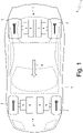
Figure 1 is a schematic plan view of an electrically propelled road vehicle provided with a power storage system made in accordance with the present invention; -
Figure 2 is an exploded perspective view, with parts removed for clarity, of the power storage system of the vehicle ofFigure 1 ; -
Figure 3 is a perspective view of a module of the power storage system ofFigure 2 ; -
Figure 4 is a perspective view, with parts removed for clarity, of a module of the power storage system ofFigure 2 ; -
Figure 5 is a perspective view, with parts removed for clarity, of a container of the power storage system ofFigure 2 ; -
Figure 6 is a plan view, with parts removed for clarity, of the container ofFigure 5 ; and -
Figure 7 is a section according to line VII-VII of several modules adjacent to one another of the power storage system ofFigure 2 . - In
Figure 1 ,reference numeral 1 indicates, as a whole, an electrically propelled vehicle provided with four driving wheels 2 (twofront driving wheels 2 and two rear driving wheels 2). - The
vehicle 1 comprises anelectric powertrain system 3 arranged in front position (i.e. is connected to the two front driving wheels 2) and anelectric powertrain system 3 which is arranged in rear position (i.e. is connected to the two rear driving wheels 2), is structurally totally identical to theelectric powertrain system 3 arranged in front position, and is mechanically totally independent of and separate from theelectric powertrain system 3 arranged in front position. - According to a different embodiment not illustrated, the
vehicle 1 comprises a single electric powertrain system 3 (arranged in front position or arranged in rear position) and thus has only twodriving wheels 2; in this embodiment, thevehicle 1 could also comprise a thermal powertrain system connected to thedriving wheels 2 that do not receive the motion from theelectric powertrain system 3. - Each
electric powertrain system 3 comprises a pair of reversible electric machines 4 (i.e. which can operate both as electric motor absorbing electric energy and generating a driving mechanical torque, and as electric generator absorbing mechanical energy and generating electric energy) provided with respective shafts and a pair oftransmissions 5 which connect the electric machines 4 (i.e. shafts of the electric machines 4) to thecorresponding driving wheels 2 without the interposition of any clutch. - Each
electric machine 4 is driven by a corresponding AC/DC electronic power converter (i.e. an inverter) which is connected to apower storage system 6 provided with chemical batteries; i.e. each DC-AC electronic power converter is bidirectional and comprises a side in direct current connected to thepower storage system 6 and a side in three-phase alternating current which is connected to the correspondingelectric machine 4. - According to what illustrated in
Figure 2 , thepower storage system 6 has a flat and (relatively) thin shape so as to be integrated inside the floor of thevehicle 1. - The
power storage system 6 comprises acontainer 7 having a lower wall 8 (which constitutes the bottom of thevehicle 1 facing the road surface and is obviously oriented horizontally), an upper wall (not illustrated and oriented horizontally) and a side wall 9 (oriented vertically) which is perpendicular to the lower andupper walls 8 and connects the lower andupper walls 8 to one another. - The
power storage system 6 comprises a plurality of modules 10 (in particular fifteen modules 10), each of which is arranged in thecontainer 7, is (initially) separate from and independent of theother modules 10, and houses inside therein a group of electrochemical cells 11 (illustrated inFigure 4 ) of parallelepiped shape (i.e. having a pouch structure or a prismatic structure). In asame module 10, theelectrochemical cells 11 can be electrically connected to one another only in series or both in series and in parallel. Thevarious modules 10 can be electrically connected to one another in series and/or in parallel. - According to what illustrated in
Figures 3 and4 , eachmodule 10 comprises a group ofelectrochemical cells 11 of parallelepiped shape which is contained in a dismountable case. Each case comprises two containingwalls 12 which are perpendicular to thelower wall 8 of thecontainer 7 and are arranged parallel to one another on opposite sides of the group ofelectrochemical cells 11 so as to clamp the pack ofelectrochemical cells 11 between them. Furthermore, each case comprises twohead walls 13 which are arranged perpendicularly both to the two containingwalls 12 and to thelower wall 8 of thecontainer 7. Lastly, each case comprises alower wall 14 and anupper wall 15 which are arranged perpendicularly to the two containingwalls 12 and are arranged parallel to thelower wall 8 of thecontainer 7; in particular, thelower wall 14 of each case rests on thelower wall 8 of thecontainer 7. - The
lower wall 14 and/or theupper wall 15 of each case can comprise a liquid heat exchanger which is used for air-conditioning (i.e. for cooling or for heating) the group ofelectrochemical cells 11. - In each case, the containing
walls 12 are the most mechanically sturdy (resistant) component, i.e. the containingwalls 12 have a greater mechanical sturdiness (resistance) than a mechanical sturdiness (resistance) of thehead walls 13, of thelower wall 14 and of theupper wall 15. The greater mechanical sturdiness (resistance) of the containingwalls 12 is immediately apparent observingFigure 4 : the walls 13-15 are substantially rather thin flat sheets, whereas the containingwalls 12 have a greater thickness and also stiffening ribs of relevant dimension. - According to a preferred embodiment, each
module 10 comprises tie rods which push the two corresponding containingwalls 12 towards one another so as to clamp the group ofelectrochemical cells 11 between them in a pack manner with a predetermined clamping strength (and necessary for the good operation of theelectrochemical cells 11 when theelectrochemical cells 11 are of pouch type). - According to a preferred embodiment illustrated in the accompanying figures, the
power storage system 6 is configured to be mounted in thevehicle 1 so as to place the containingwalls 12 of themodules 10 crosswise relative to a forward direction D of the vehicle 1 (illustrated inFigure 1 ); i.e. when thepower storage system 6 is mounted in thevehicle 1 all the containingwalls 12 of themodules 10 are placed crosswise (i.e. perpendicular to the forward direction D of the vehicle 1). - Each containing
wall 12 has a series oftubular connection bodies 16, i.e. a series ofconnection bodies 16 each having a central through cavity which passes through theconnection body 16 from side to side (in other words, theconnection bodies 16 are centrally holed). In the preferred embodiment illustrated in the accompanying figures, theconnection bodies 16 have a cylindrical shape (thus also their central cavities have a cylindrical shape). - According to what illustrated in
Figure 5 , thepower storage system 6 comprises a plurality oflocking elements 17 of cylindrical shape which are fixed to thelower wall 8 of thecontainer 7 and project perpendicularly from the lower wall 8 (thus thelocking elements 17 are vertically oriented). Thelocking elements 17 are configured to engagecorresponding connection bodies 16, i.e. to engage the central cavities (without relevant clearance) of thecorresponding connection bodies 16. - According to a preferred embodiment, each
locking element 17 consists of a stud which has both two ends threaded: a lower end of eachlocking element 17 is screwed in a blind threaded hole 18 (illustrated inFigure 7 ) made through thelower wall 8 of thecontainer 7 whereas an upper end of eachlocking element 17 is engaged by a nut 19 (illustrated inFigure 7 ) which is screwed to acorresponding locking element 17 and is tightened so as to push at least onecorresponding connection body 16 towards thelower wall 8 of the container 7 (i.e. to maintain thecorresponding module 10 pressed with a given strength against thelower wall 8 of the container 7). - According to what illustrated in
Figure 7 , thelower wall 8 of thecontainer 7 has reinforcements in the area of the blind threadedholes 18. - According to what illustrated in
Figure 3 , each containingwall 12 hasseveral connection bodies 16 which are arranged both in the area of edges of the containingwall 12, and between the edges of the containingwall 12. In particular, in the embodiment illustrated inFigure 3 , each containingwall 12 has twoconnection bodies 16 arranged (laterally) in the area of the edges of the containingwall 12 and twofurther connection bodies 16 arranged (centrally) between the edges of the containingwall 12; i.e. in all each containingwall 12 has fourconnection bodies 16 arranged two (laterally) on the sides of the containingwall 12 and two (centrally) between the edges of the containingwall 12. - According to what illustrated in
Figure 7 , twoadjacent modules 10 have at least twocorresponding connection bodies 16 which are aligned with and overlap one another and are both engaged by asame locking element 17; i.e. asame locking element 17 engages aconnection body 16 of amodule 10 and also aconnection body 16 of anotheradjacent module 10. Consequently, twoconnection bodies 16 engaged by asame locking element 17 are arranged in different positions along thelocking element 17, i.e. are arranged vertically staggered (being thelocking elements 17 arranged vertically) so as to be arranged coaxial to one another. - According to what illustrated in
Figure 3 , each containingwall 12 has tworecesses 20 which reproduce in negative the shape of aconnection body 16 and house aconnection body 16 of an adjacent containing wall 12 (as illustrated inFigure 7 ) thus creating an interlocking coupling. - In other words, a containing
wall 12 has at least one first connection body 16 (actually two in the illustrated embodiment) and at least onefirst recess 20 which reproduces in negative the shape of aconnection body 16 and is coaxial to thefirst connection body 16, asecond containing wall 12 which is adjacent to and rests against the first containingwall 12, has at least one second connection body 16 (actually two in the illustrated embodiment) and at least onesecond recess 20, which reproduces in negative the shape of aconnection body 16 and is coaxial to thesecond connection body 16; when thepower storage system 6 is mounted, eachfirst connection body 16 of the first containingwall 12 engages a correspondingsecond recess 20 of the second containing wall and, in the same manner, eachsecond connection body 16 of thesecond containing wall 12 engages the correspondingfirst recess 20 of the first containingwall 12, thus creating an interlocking coupling (illustrated inFigure 7 ). Obviously, as mentioned in the foregoing, afirst connection body 16 of the first containingwall 12 is arranged vertically staggered relative to a correspondingsecond connection body 16 of thesecond containing wall 12 so that the twoconnection bodies 16 can be coaxial to one another and thus can be engaged by asame locking element 17. - In other words, each containing
wall 12 has for eachconnection body 16 arranged between the edges of the containing wall 12 acorresponding recess 20 which reproduces in negative the shape of aconnection body 16 and is coaxial to theconnection body 16. - In
Figure 2 ,rivets 21 are also visible which are connected to thelower wall 8 of thecontainer 7 and are necessary for the fixing of a sub-base. - The embodiments described herein can be combined with one another.
- The
power storage system 6 described above has numerous advantages. - Firstly, the
power storage system 6 described above allows contributing in a relevant manner to the mechanical resistance and to the sturdiness of the floor of thevehicle 1. - Furthermore, the
power storage system 6 described above has a sensible reduction in weight with respect to an analogous knownpower storage system 6 since inside therein it is completely devoid of stiffening elements (i.e. it is completely devoid of struts and crosspieces). - Finally, the cost and the production complexity of the
power storage system 6 described above are relatively reduced. -
- 1
- vehicle
- 2
- wheels
- 3
- powertrain system
- 4
- electric machine
- 5
- transmission
- 6
- power storage system
- 7
- container
- 8
- lower wall
- 9
- side wall
- 10
- module
- 11
- electrochemical cells
- 12
- containing walls
- 13
- head walls
- 14
- lower wall
- 15
- upper wall
- 16
- connection bodies
- 17
- locking elements
- 18
- threaded hole
- 19
- nut
- 20
- recess
- 21
- rivets
- D
- forward direction
Claims (15)
- A power storage system (6) for a vehicle (1) provided with at least one electric motor (4); the power storage system (6) comprises:a container (7) provided with a lower wall (8); anda plurality of modules (10), which are housed inside the container (7) and directly rest on the lower wall (8);wherein each module (10) comprises a group of electrochemical cells (11) and two containing walls (12), which are perpendicular to the lower wall (8) of the container (7) and are arranged parallel to one another on opposite sides of the group of electrochemical cells (11) so as to clamp the group of electrochemical cells (11) between them;wherein each containing wall (12) has at least one tubular connection body (16); andwherein a plurality of locking elements (17) are provided, which are fixed to the lower wall (8), project perpendicularly from the lower wall (8) and engage the connection bodies (16);the power storage system (6) is characterized in that at least two adjacent modules (10) have two corresponding connection bodies (16) which are aligned with and overlap one another and are both engaged by a same locking element (17) .
- The power storage system (6) according to claim 1, wherein:each locking element (17) is at least partially threaded; anda plurality of nuts (19) are provided, each screwed to a corresponding locking element (17) and tightened so as to push at least one corresponding connection body (16) towards the lower wall (8) of the container (7).
- The power storage system (6) according to claim 1 or 2, wherein a same locking element (17) engages a connection body (16) of a module (10) and also a connection body (16) of another adjacent module (10) and consequently two connection bodies (16) engaged by a same locking element (17) are arranged in different positions along the locking element (17), i.e. are arranged vertically staggered so as to be arranged coaxial to one another.
- The power storage system (6) according to claim 1, 2 or 3, wherein two connection bodies (16) engaged by a same locking element (17) are arranged in different positions along the locking element (17).
- The power storage system (6) according to one of the claims from 1 to 4, wherein at least one containing wall (12) has a recess (20), which reproduces in negative the shape of a connection body (16) and houses a connection body (16) of an adjacent containing wall (12), thus creating an interlocking coupling.
- The power storage system (6) according to one of the claims from 1 to 5, wherein:a first containing wall (12) has at least one first connection body (16) and at least one first recess (20), which reproduces in negative the shape of a connection body (16) and is coaxial to the first connection body (16);a second containing wall (12), which is adjacent to and rests against the first containing wall (12), has at least one second connection body (16) and at least one second recess (20), which reproduces in negative the shape of a connection body (16) and is coaxial to the second connection body (16);the first connection body (16) of the first containing wall (12) engages the second recess (20) of the second containing wall (12); andthe second connection body (16) of the second containing wall (12) engages the first recess (20) of the first containing wall (12), thus creating an interlocking coupling.
- The power storage system (6) according to one of the claims from 1 to 6, wherein:each locking element (17) is at least partially threaded; andthe lower wall (8) of the container (7) has a plurality of threaded holes (18), into which the locking elements (17) are screwed.
- The power storage system (6) according to one of the claims from 1 to 7, wherein the locking elements (17) consist of studs.
- The power storage system (6) according to one of the claims from 1 to 8, wherein each containing wall (12) has several connection bodies (16), which are arranged both in the area of the edges of the containing wall (12) and between the edges of the containing wall (12).
- The power storage system (6) according to claim 9, wherein each containing wall (12) has two connection bodies (16), which are arranged in the area of the edges of the containing wall (12), and two further connection bodies (16), which are arranged between the edges of the containing wall (12) .
- The power storage system (6) according to claim 9 or 10, wherein each containing wall (12) has, for each connection body (16) arranged between the edges of the containing wall (12), a corresponding recess (20), which reproduces in negative the shape of a connection body (16) and is coaxial to the connection body (16).
- The power storage system (6) according to one of the claims from 1 to 11, wherein each module (10) comprises tie rods, which push the two corresponding containing walls (12) towards one another.
- The power storage system (6) according to one of the claims from 1 to 12, wherein each module (10) comprises two head walls (13), which are arranged perpendicularly to the two containing walls (12) and have a smaller mechanical sturdiness than a mechanical sturdiness of the containing walls (12).
- The power storage system (6) according to one of the claims from 1 to 13, wherein each module (10) comprises a lower wall (14) and an upper wall (15), which are arranged perpendicularly to the two containing walls (12) and have a smaller mechanical sturdiness than a mechanical sturdiness of the containing walls (12).
- An electrically propelled vehicle (1) comprising:four wheels (2);at least one electric powertrain system (3) comprising at least one reversible electric machine (4);
anda power storage system (6) according to one of the claims from 1 to 14 and configured to be mounted in the vehicle (1) so as to place the containing walls (12) crosswise relative to a forward direction (D) of the vehicle.
Applications Claiming Priority (1)
| Application Number | Priority Date | Filing Date | Title |
|---|---|---|---|
| IT102020000026545A IT202000026545A1 (en) | 2020-11-06 | 2020-11-06 | ELECTRIC ENERGY STORAGE SYSTEM FOR A VEHICLE EQUIPPED WITH AT LEAST ONE ELECTRIC MOTOR |
Publications (2)
| Publication Number | Publication Date |
|---|---|
| EP3996177A1 true EP3996177A1 (en) | 2022-05-11 |
| EP3996177B1 EP3996177B1 (en) | 2023-11-01 |
Family
ID=74347543
Family Applications (1)
| Application Number | Title | Priority Date | Filing Date |
|---|---|---|---|
| EP21206804.3A Active EP3996177B1 (en) | 2020-11-06 | 2021-11-05 | Power storage system for a vehicle provided with at least one electric motor |
Country Status (5)
| Country | Link |
|---|---|
| US (1) | US11923553B2 (en) |
| EP (1) | EP3996177B1 (en) |
| JP (1) | JP7817814B2 (en) |
| CN (1) | CN114447489A (en) |
| IT (1) | IT202000026545A1 (en) |
Cited By (2)
| Publication number | Priority date | Publication date | Assignee | Title |
|---|---|---|---|---|
| EP4362189A1 (en) * | 2022-10-31 | 2024-05-01 | FERRARI S.p.A. | Vehicle provided with a power storage system |
| US12617262B2 (en) | 2023-10-25 | 2026-05-05 | Ferrari S.P.A. | Vehicle provided with a power storage system |
Families Citing this family (2)
| Publication number | Priority date | Publication date | Assignee | Title |
|---|---|---|---|---|
| KR20230160167A (en) * | 2022-05-16 | 2023-11-23 | 주식회사 엘지에너지솔루션 | Battery pack |
| IT202300026556A1 (en) * | 2023-12-13 | 2025-06-13 | Ferrari Spa | VEHICLE BATTERY PACK WITH SHAPED POUCH CELLS |
Citations (4)
| Publication number | Priority date | Publication date | Assignee | Title |
|---|---|---|---|---|
| US20100187027A1 (en) * | 2009-01-28 | 2010-07-29 | Tsuyoshi Komaki | Battery system with battery holders |
| CN106935747A (en) * | 2015-12-31 | 2017-07-07 | 深圳市沃特玛电池有限公司 | The battery modules of electric automobile |
| US20180114961A1 (en) | 2016-10-21 | 2018-04-26 | Lg Chem, Ltd. | Battery pack including coupling member having assembling guide function |
| US20180337377A1 (en) * | 2017-05-16 | 2018-11-22 | Shape Corp. | Vehicle battery tray having tub-based integration |
Family Cites Families (8)
| Publication number | Priority date | Publication date | Assignee | Title |
|---|---|---|---|---|
| CN102640347B (en) | 2009-12-07 | 2015-12-02 | 住友重机械工业株式会社 | Excavator |
| JP5873210B2 (en) | 2013-02-18 | 2016-03-01 | 日立オートモティブシステムズ株式会社 | Battery block and secondary battery module |
| KR101948180B1 (en) | 2015-04-30 | 2019-02-14 | 주식회사 엘지화학 | Battery pack and method for manufacturing the same |
| KR102162968B1 (en) | 2017-04-07 | 2020-10-07 | 주식회사 엘지화학 | Battery Pack with extendible battery module |
| WO2019021912A1 (en) | 2017-07-28 | 2019-01-31 | パナソニックIpマネジメント株式会社 | Linked battery module and linked battery pack |
| US10611234B1 (en) * | 2019-02-06 | 2020-04-07 | Ford Global Technologies, Llc | Battery assembly with supportive thermal exchange device and thermal management method using same |
| KR102844872B1 (en) * | 2020-04-17 | 2025-08-08 | 주식회사 엘지에너지솔루션 | A battery module having a flame discharge prevention structure, a battery pack, a vehicle and an energy storage system including the same |
| KR20220052183A (en) * | 2020-10-20 | 2022-04-27 | 현대자동차주식회사 | Battery module and battery pack comprising the same |
-
2020
- 2020-11-06 IT IT102020000026545A patent/IT202000026545A1/en unknown
-
2021
- 2021-11-04 CN CN202111303278.2A patent/CN114447489A/en active Pending
- 2021-11-05 EP EP21206804.3A patent/EP3996177B1/en active Active
- 2021-11-05 JP JP2021181446A patent/JP7817814B2/en active Active
- 2021-11-05 US US17/519,703 patent/US11923553B2/en active Active
Patent Citations (4)
| Publication number | Priority date | Publication date | Assignee | Title |
|---|---|---|---|---|
| US20100187027A1 (en) * | 2009-01-28 | 2010-07-29 | Tsuyoshi Komaki | Battery system with battery holders |
| CN106935747A (en) * | 2015-12-31 | 2017-07-07 | 深圳市沃特玛电池有限公司 | The battery modules of electric automobile |
| US20180114961A1 (en) | 2016-10-21 | 2018-04-26 | Lg Chem, Ltd. | Battery pack including coupling member having assembling guide function |
| US20180337377A1 (en) * | 2017-05-16 | 2018-11-22 | Shape Corp. | Vehicle battery tray having tub-based integration |
Cited By (3)
| Publication number | Priority date | Publication date | Assignee | Title |
|---|---|---|---|---|
| EP4362189A1 (en) * | 2022-10-31 | 2024-05-01 | FERRARI S.p.A. | Vehicle provided with a power storage system |
| IT202200022350A1 (en) * | 2022-10-31 | 2024-05-01 | Ferrari Spa | VEHICLE EQUIPPED WITH AN ELECTRIC ENERGY STORAGE SYSTEM |
| US12617262B2 (en) | 2023-10-25 | 2026-05-05 | Ferrari S.P.A. | Vehicle provided with a power storage system |
Also Published As
| Publication number | Publication date |
|---|---|
| CN114447489A (en) | 2022-05-06 |
| US11923553B2 (en) | 2024-03-05 |
| JP7817814B2 (en) | 2026-02-19 |
| JP2022075653A (en) | 2022-05-18 |
| IT202000026545A1 (en) | 2022-05-06 |
| US20220149467A1 (en) | 2022-05-12 |
| EP3996177B1 (en) | 2023-11-01 |
Similar Documents
| Publication | Publication Date | Title |
|---|---|---|
| EP3996177B1 (en) | Power storage system for a vehicle provided with at least one electric motor | |
| US10625589B2 (en) | Battery mounting structure for vehicle | |
| US11135910B2 (en) | Electric kart and battery | |
| CN109390540B (en) | Traction battery assembly with multi-component busbar module | |
| WO2019031169A1 (en) | Battery module and vehicle equipped with same | |
| US10199621B2 (en) | Battery cell spacer for establishing dielectric barriers within a battery assembly | |
| US11876202B2 (en) | Systematic layouts for electrified vehicle traction battery packs | |
| KR20230056613A (en) | Battery frame, battery pack, electric vehicle, method of assembling a battery frame, and method of assembling a battery pack | |
| US20250192264A1 (en) | Multi-function barrier trays for use within traction battery packs | |
| CN111081922A (en) | Power storage unit and power storage device | |
| US10720619B2 (en) | Array frame mounting inserts for securing battery assemblies | |
| CN106374065B (en) | Battery assembly array plate | |
| US20230387526A1 (en) | Traction battery packs with mixed material tray structures | |
| US12617262B2 (en) | Vehicle provided with a power storage system | |
| US20240140187A1 (en) | Vehicle provided with a power storage system | |
| US20240079679A1 (en) | Multi-functional cross-member assembles for traction battery packs | |
| US20260100465A1 (en) | Traction battery pack cell stack designs for establishing sealed interfaces | |
| US20250118852A1 (en) | Battery arrays with multi-piece dividing wall structures | |
| US20260031493A1 (en) | Bus bar assemblies with arched bus bar plates | |
| CN117691284A (en) | Multifunctional beam assembly for traction battery pack | |
| CN117691286A (en) | Structural cross member assembly for traction battery pack |
Legal Events
| Date | Code | Title | Description |
|---|---|---|---|
| PUAI | Public reference made under article 153(3) epc to a published international application that has entered the european phase |
Free format text: ORIGINAL CODE: 0009012 |
|
| STAA | Information on the status of an ep patent application or granted ep patent |
Free format text: STATUS: THE APPLICATION HAS BEEN PUBLISHED |
|
| AK | Designated contracting states |
Kind code of ref document: A1 Designated state(s): AL AT BE BG CH CY CZ DE DK EE ES FI FR GB GR HR HU IE IS IT LI LT LU LV MC MK MT NL NO PL PT RO RS SE SI SK SM TR |
|
| STAA | Information on the status of an ep patent application or granted ep patent |
Free format text: STATUS: REQUEST FOR EXAMINATION WAS MADE |
|
| 17P | Request for examination filed |
Effective date: 20221110 |
|
| GRAP | Despatch of communication of intention to grant a patent |
Free format text: ORIGINAL CODE: EPIDOSNIGR1 |
|
| STAA | Information on the status of an ep patent application or granted ep patent |
Free format text: STATUS: GRANT OF PATENT IS INTENDED |
|
| INTG | Intention to grant announced |
Effective date: 20230524 |
|
| P01 | Opt-out of the competence of the unified patent court (upc) registered |
Effective date: 20230525 |
|
| GRAS | Grant fee paid |
Free format text: ORIGINAL CODE: EPIDOSNIGR3 |
|
| GRAA | (expected) grant |
Free format text: ORIGINAL CODE: 0009210 |
|
| STAA | Information on the status of an ep patent application or granted ep patent |
Free format text: STATUS: THE PATENT HAS BEEN GRANTED |
|
| AK | Designated contracting states |
Kind code of ref document: B1 Designated state(s): AL AT BE BG CH CY CZ DE DK EE ES FI FR GB GR HR HU IE IS IT LI LT LU LV MC MK MT NL NO PL PT RO RS SE SI SK SM TR |
|
| REG | Reference to a national code |
Ref country code: GB Ref legal event code: FG4D |
|
| REG | Reference to a national code |
Ref country code: CH Ref legal event code: EP |
|
| REG | Reference to a national code |
Ref country code: DE Ref legal event code: R096 Ref document number: 602021006401 Country of ref document: DE |
|
| REG | Reference to a national code |
Ref country code: IE Ref legal event code: FG4D |
|
| REG | Reference to a national code |
Ref country code: LT Ref legal event code: MG9D |
|
| REG | Reference to a national code |
Ref country code: NL Ref legal event code: MP Effective date: 20231101 |
|
| PG25 | Lapsed in a contracting state [announced via postgrant information from national office to epo] |
Ref country code: GR Free format text: LAPSE BECAUSE OF FAILURE TO SUBMIT A TRANSLATION OF THE DESCRIPTION OR TO PAY THE FEE WITHIN THE PRESCRIBED TIME-LIMIT Effective date: 20240202 |
|
| PG25 | Lapsed in a contracting state [announced via postgrant information from national office to epo] |
Ref country code: IS Free format text: LAPSE BECAUSE OF FAILURE TO SUBMIT A TRANSLATION OF THE DESCRIPTION OR TO PAY THE FEE WITHIN THE PRESCRIBED TIME-LIMIT Effective date: 20240301 |
|
| PG25 | Lapsed in a contracting state [announced via postgrant information from national office to epo] |
Ref country code: LT Free format text: LAPSE BECAUSE OF FAILURE TO SUBMIT A TRANSLATION OF THE DESCRIPTION OR TO PAY THE FEE WITHIN THE PRESCRIBED TIME-LIMIT Effective date: 20231101 |
|
| REG | Reference to a national code |
Ref country code: AT Ref legal event code: MK05 Ref document number: 1628267 Country of ref document: AT Kind code of ref document: T Effective date: 20231101 |
|
| PG25 | Lapsed in a contracting state [announced via postgrant information from national office to epo] |
Ref country code: NL Free format text: LAPSE BECAUSE OF FAILURE TO SUBMIT A TRANSLATION OF THE DESCRIPTION OR TO PAY THE FEE WITHIN THE PRESCRIBED TIME-LIMIT Effective date: 20231101 |
|
| PG25 | Lapsed in a contracting state [announced via postgrant information from national office to epo] |
Ref country code: AT Free format text: LAPSE BECAUSE OF FAILURE TO SUBMIT A TRANSLATION OF THE DESCRIPTION OR TO PAY THE FEE WITHIN THE PRESCRIBED TIME-LIMIT Effective date: 20231101 |
|
| PG25 | Lapsed in a contracting state [announced via postgrant information from national office to epo] |
Ref country code: ES Free format text: LAPSE BECAUSE OF FAILURE TO SUBMIT A TRANSLATION OF THE DESCRIPTION OR TO PAY THE FEE WITHIN THE PRESCRIBED TIME-LIMIT Effective date: 20231101 |
|
| PG25 | Lapsed in a contracting state [announced via postgrant information from national office to epo] |
Ref country code: NL Free format text: LAPSE BECAUSE OF FAILURE TO SUBMIT A TRANSLATION OF THE DESCRIPTION OR TO PAY THE FEE WITHIN THE PRESCRIBED TIME-LIMIT Effective date: 20231101 Ref country code: LT Free format text: LAPSE BECAUSE OF FAILURE TO SUBMIT A TRANSLATION OF THE DESCRIPTION OR TO PAY THE FEE WITHIN THE PRESCRIBED TIME-LIMIT Effective date: 20231101 Ref country code: IT Free format text: LAPSE BECAUSE OF NON-PAYMENT OF DUE FEES Effective date: 20231105 Ref country code: IS Free format text: LAPSE BECAUSE OF FAILURE TO SUBMIT A TRANSLATION OF THE DESCRIPTION OR TO PAY THE FEE WITHIN THE PRESCRIBED TIME-LIMIT Effective date: 20240301 Ref country code: GR Free format text: LAPSE BECAUSE OF FAILURE TO SUBMIT A TRANSLATION OF THE DESCRIPTION OR TO PAY THE FEE WITHIN THE PRESCRIBED TIME-LIMIT Effective date: 20240202 Ref country code: ES Free format text: LAPSE BECAUSE OF FAILURE TO SUBMIT A TRANSLATION OF THE DESCRIPTION OR TO PAY THE FEE WITHIN THE PRESCRIBED TIME-LIMIT Effective date: 20231101 Ref country code: BG Free format text: LAPSE BECAUSE OF FAILURE TO SUBMIT A TRANSLATION OF THE DESCRIPTION OR TO PAY THE FEE WITHIN THE PRESCRIBED TIME-LIMIT Effective date: 20240201 Ref country code: AT Free format text: LAPSE BECAUSE OF FAILURE TO SUBMIT A TRANSLATION OF THE DESCRIPTION OR TO PAY THE FEE WITHIN THE PRESCRIBED TIME-LIMIT Effective date: 20231101 Ref country code: PT Free format text: LAPSE BECAUSE OF FAILURE TO SUBMIT A TRANSLATION OF THE DESCRIPTION OR TO PAY THE FEE WITHIN THE PRESCRIBED TIME-LIMIT Effective date: 20240301 |
|
| PG25 | Lapsed in a contracting state [announced via postgrant information from national office to epo] |
Ref country code: SE Free format text: LAPSE BECAUSE OF FAILURE TO SUBMIT A TRANSLATION OF THE DESCRIPTION OR TO PAY THE FEE WITHIN THE PRESCRIBED TIME-LIMIT Effective date: 20231101 Ref country code: RS Free format text: LAPSE BECAUSE OF FAILURE TO SUBMIT A TRANSLATION OF THE DESCRIPTION OR TO PAY THE FEE WITHIN THE PRESCRIBED TIME-LIMIT Effective date: 20231101 Ref country code: PL Free format text: LAPSE BECAUSE OF FAILURE TO SUBMIT A TRANSLATION OF THE DESCRIPTION OR TO PAY THE FEE WITHIN THE PRESCRIBED TIME-LIMIT Effective date: 20231101 Ref country code: NO Free format text: LAPSE BECAUSE OF FAILURE TO SUBMIT A TRANSLATION OF THE DESCRIPTION OR TO PAY THE FEE WITHIN THE PRESCRIBED TIME-LIMIT Effective date: 20240201 Ref country code: LV Free format text: LAPSE BECAUSE OF FAILURE TO SUBMIT A TRANSLATION OF THE DESCRIPTION OR TO PAY THE FEE WITHIN THE PRESCRIBED TIME-LIMIT Effective date: 20231101 Ref country code: HR Free format text: LAPSE BECAUSE OF FAILURE TO SUBMIT A TRANSLATION OF THE DESCRIPTION OR TO PAY THE FEE WITHIN THE PRESCRIBED TIME-LIMIT Effective date: 20231101 |
|
| PG25 | Lapsed in a contracting state [announced via postgrant information from national office to epo] |
Ref country code: DK Free format text: LAPSE BECAUSE OF FAILURE TO SUBMIT A TRANSLATION OF THE DESCRIPTION OR TO PAY THE FEE WITHIN THE PRESCRIBED TIME-LIMIT Effective date: 20231101 |
|
| PG25 | Lapsed in a contracting state [announced via postgrant information from national office to epo] |
Ref country code: LU Free format text: LAPSE BECAUSE OF NON-PAYMENT OF DUE FEES Effective date: 20231105 |
|
| PG25 | Lapsed in a contracting state [announced via postgrant information from national office to epo] |
Ref country code: CZ Free format text: LAPSE BECAUSE OF FAILURE TO SUBMIT A TRANSLATION OF THE DESCRIPTION OR TO PAY THE FEE WITHIN THE PRESCRIBED TIME-LIMIT Effective date: 20231101 |
|
| PG25 | Lapsed in a contracting state [announced via postgrant information from national office to epo] |
Ref country code: SK Free format text: LAPSE BECAUSE OF FAILURE TO SUBMIT A TRANSLATION OF THE DESCRIPTION OR TO PAY THE FEE WITHIN THE PRESCRIBED TIME-LIMIT Effective date: 20231101 |
|
| PG25 | Lapsed in a contracting state [announced via postgrant information from national office to epo] |
Ref country code: SM Free format text: LAPSE BECAUSE OF FAILURE TO SUBMIT A TRANSLATION OF THE DESCRIPTION OR TO PAY THE FEE WITHIN THE PRESCRIBED TIME-LIMIT Effective date: 20231101 Ref country code: SK Free format text: LAPSE BECAUSE OF FAILURE TO SUBMIT A TRANSLATION OF THE DESCRIPTION OR TO PAY THE FEE WITHIN THE PRESCRIBED TIME-LIMIT Effective date: 20231101 Ref country code: EE Free format text: LAPSE BECAUSE OF FAILURE TO SUBMIT A TRANSLATION OF THE DESCRIPTION OR TO PAY THE FEE WITHIN THE PRESCRIBED TIME-LIMIT Effective date: 20231101 Ref country code: DK Free format text: LAPSE BECAUSE OF FAILURE TO SUBMIT A TRANSLATION OF THE DESCRIPTION OR TO PAY THE FEE WITHIN THE PRESCRIBED TIME-LIMIT Effective date: 20231101 Ref country code: CZ Free format text: LAPSE BECAUSE OF FAILURE TO SUBMIT A TRANSLATION OF THE DESCRIPTION OR TO PAY THE FEE WITHIN THE PRESCRIBED TIME-LIMIT Effective date: 20231101 Ref country code: LU Free format text: LAPSE BECAUSE OF NON-PAYMENT OF DUE FEES Effective date: 20231105 |
|
| REG | Reference to a national code |
Ref country code: BE Ref legal event code: MM Effective date: 20231130 |
|
| REG | Reference to a national code |
Ref country code: DE Ref legal event code: R097 Ref document number: 602021006401 Country of ref document: DE |
|
| PG25 | Lapsed in a contracting state [announced via postgrant information from national office to epo] |
Ref country code: MC Free format text: LAPSE BECAUSE OF FAILURE TO SUBMIT A TRANSLATION OF THE DESCRIPTION OR TO PAY THE FEE WITHIN THE PRESCRIBED TIME-LIMIT Effective date: 20231101 |
|
| PG25 | Lapsed in a contracting state [announced via postgrant information from national office to epo] |
Ref country code: MC Free format text: LAPSE BECAUSE OF FAILURE TO SUBMIT A TRANSLATION OF THE DESCRIPTION OR TO PAY THE FEE WITHIN THE PRESCRIBED TIME-LIMIT Effective date: 20231101 |
|
| PLBE | No opposition filed within time limit |
Free format text: ORIGINAL CODE: 0009261 |
|
| STAA | Information on the status of an ep patent application or granted ep patent |
Free format text: STATUS: NO OPPOSITION FILED WITHIN TIME LIMIT |
|
| REG | Reference to a national code |
Ref country code: IE Ref legal event code: MM4A |
|
| 26N | No opposition filed |
Effective date: 20240802 |
|
| PG25 | Lapsed in a contracting state [announced via postgrant information from national office to epo] |
Ref country code: IE Free format text: LAPSE BECAUSE OF NON-PAYMENT OF DUE FEES Effective date: 20231105 |
|
| PG25 | Lapsed in a contracting state [announced via postgrant information from national office to epo] |
Ref country code: BE Free format text: LAPSE BECAUSE OF NON-PAYMENT OF DUE FEES Effective date: 20231130 |
|
| PG25 | Lapsed in a contracting state [announced via postgrant information from national office to epo] |
Ref country code: SI Free format text: LAPSE BECAUSE OF FAILURE TO SUBMIT A TRANSLATION OF THE DESCRIPTION OR TO PAY THE FEE WITHIN THE PRESCRIBED TIME-LIMIT Effective date: 20231101 |
|
| PG25 | Lapsed in a contracting state [announced via postgrant information from national office to epo] |
Ref country code: SI Free format text: LAPSE BECAUSE OF FAILURE TO SUBMIT A TRANSLATION OF THE DESCRIPTION OR TO PAY THE FEE WITHIN THE PRESCRIBED TIME-LIMIT Effective date: 20231101 Ref country code: IE Free format text: LAPSE BECAUSE OF NON-PAYMENT OF DUE FEES Effective date: 20231105 Ref country code: BE Free format text: LAPSE BECAUSE OF NON-PAYMENT OF DUE FEES Effective date: 20231130 |
|
| PG25 | Lapsed in a contracting state [announced via postgrant information from national office to epo] |
Ref country code: IT Free format text: LAPSE BECAUSE OF NON-PAYMENT OF DUE FEES Effective date: 20231105 |
|
| PGRI | Patent reinstated in contracting state [announced from national office to epo] |
Ref country code: IT Effective date: 20231130 |
|
| PG25 | Lapsed in a contracting state [announced via postgrant information from national office to epo] |
Ref country code: IT Free format text: LAPSE BECAUSE OF NON-PAYMENT OF DUE FEES Effective date: 20231105 |
|
| PGRI | Patent reinstated in contracting state [announced from national office to epo] |
Ref country code: IT Effective date: 20231130 |
|
| PG25 | Lapsed in a contracting state [announced via postgrant information from national office to epo] |
Ref country code: RO Free format text: LAPSE BECAUSE OF FAILURE TO SUBMIT A TRANSLATION OF THE DESCRIPTION OR TO PAY THE FEE WITHIN THE PRESCRIBED TIME-LIMIT Effective date: 20231101 |
|
| REG | Reference to a national code |
Ref country code: CH Ref legal event code: PL |
|
| PG25 | Lapsed in a contracting state [announced via postgrant information from national office to epo] |
Ref country code: FI Free format text: LAPSE BECAUSE OF FAILURE TO SUBMIT A TRANSLATION OF THE DESCRIPTION OR TO PAY THE FEE WITHIN THE PRESCRIBED TIME-LIMIT Effective date: 20231101 |
|
| REG | Reference to a national code |
Ref country code: CH Ref legal event code: PL |
|
| PG25 | Lapsed in a contracting state [announced via postgrant information from national office to epo] |
Ref country code: CH Free format text: LAPSE BECAUSE OF NON-PAYMENT OF DUE FEES Effective date: 20241130 |
|
| PG25 | Lapsed in a contracting state [announced via postgrant information from national office to epo] |
Ref country code: CY Free format text: LAPSE BECAUSE OF FAILURE TO SUBMIT A TRANSLATION OF THE DESCRIPTION OR TO PAY THE FEE WITHIN THE PRESCRIBED TIME-LIMIT; INVALID AB INITIO Effective date: 20211105 |
|
| PG25 | Lapsed in a contracting state [announced via postgrant information from national office to epo] |
Ref country code: TR Free format text: LAPSE BECAUSE OF FAILURE TO SUBMIT A TRANSLATION OF THE DESCRIPTION OR TO PAY THE FEE WITHIN THE PRESCRIBED TIME-LIMIT Effective date: 20231101 |
|
| PGFP | Annual fee paid to national office [announced via postgrant information from national office to epo] |
Ref country code: DE Payment date: 20251126 Year of fee payment: 5 |
|
| PGFP | Annual fee paid to national office [announced via postgrant information from national office to epo] |
Ref country code: GB Payment date: 20251125 Year of fee payment: 5 |
|
| PGFP | Annual fee paid to national office [announced via postgrant information from national office to epo] |
Ref country code: IT Payment date: 20251107 Year of fee payment: 5 |
|
| PGFP | Annual fee paid to national office [announced via postgrant information from national office to epo] |
Ref country code: FR Payment date: 20251124 Year of fee payment: 5 |
|
| PG25 | Lapsed in a contracting state [announced via postgrant information from national office to epo] |
Ref country code: HU Free format text: LAPSE BECAUSE OF FAILURE TO SUBMIT A TRANSLATION OF THE DESCRIPTION OR TO PAY THE FEE WITHIN THE PRESCRIBED TIME-LIMIT; INVALID AB INITIO Effective date: 20211105 |