EP3995888A1 - Stereo camera and light unit with integrated stereo camera - Google Patents
Stereo camera and light unit with integrated stereo camera Download PDFInfo
- Publication number
- EP3995888A1 EP3995888A1 EP20837915.6A EP20837915A EP3995888A1 EP 3995888 A1 EP3995888 A1 EP 3995888A1 EP 20837915 A EP20837915 A EP 20837915A EP 3995888 A1 EP3995888 A1 EP 3995888A1
- Authority
- EP
- European Patent Office
- Prior art keywords
- mirror
- light
- stereo camera
- image sensor
- reflective surface
- Prior art date
- Legal status (The legal status is an assumption and is not a legal conclusion. Google has not performed a legal analysis and makes no representation as to the accuracy of the status listed.)
- Granted
Links
Images






Classifications
-
- G—PHYSICS
- G03—PHOTOGRAPHY; CINEMATOGRAPHY; ANALOGOUS TECHNIQUES USING WAVES OTHER THAN OPTICAL WAVES; ELECTROGRAPHY; HOLOGRAPHY
- G03B—APPARATUS OR ARRANGEMENTS FOR TAKING PHOTOGRAPHS OR FOR PROJECTING OR VIEWING THEM; APPARATUS OR ARRANGEMENTS EMPLOYING ANALOGOUS TECHNIQUES USING WAVES OTHER THAN OPTICAL WAVES; ACCESSORIES THEREFOR
- G03B35/00—Stereoscopic photography
- G03B35/08—Stereoscopic photography by simultaneous recording
- G03B35/10—Stereoscopic photography by simultaneous recording having single camera with stereoscopic-base-defining system
-
- B—PERFORMING OPERATIONS; TRANSPORTING
- B60—VEHICLES IN GENERAL
- B60R—VEHICLES, VEHICLE FITTINGS, OR VEHICLE PARTS, NOT OTHERWISE PROVIDED FOR
- B60R1/00—Optical viewing arrangements; Real-time viewing arrangements for drivers or passengers using optical image capturing systems, e.g. cameras or video systems specially adapted for use in or on vehicles
- B60R1/20—Real-time viewing arrangements for drivers or passengers using optical image capturing systems, e.g. cameras or video systems specially adapted for use in or on vehicles
- B60R1/22—Real-time viewing arrangements for drivers or passengers using optical image capturing systems, e.g. cameras or video systems specially adapted for use in or on vehicles for viewing an area outside the vehicle, e.g. the exterior of the vehicle
- B60R1/23—Real-time viewing arrangements for drivers or passengers using optical image capturing systems, e.g. cameras or video systems specially adapted for use in or on vehicles for viewing an area outside the vehicle, e.g. the exterior of the vehicle with a predetermined field of view
- B60R1/24—Real-time viewing arrangements for drivers or passengers using optical image capturing systems, e.g. cameras or video systems specially adapted for use in or on vehicles for viewing an area outside the vehicle, e.g. the exterior of the vehicle with a predetermined field of view in front of the vehicle
-
- B—PERFORMING OPERATIONS; TRANSPORTING
- B60—VEHICLES IN GENERAL
- B60R—VEHICLES, VEHICLE FITTINGS, OR VEHICLE PARTS, NOT OTHERWISE PROVIDED FOR
- B60R1/00—Optical viewing arrangements; Real-time viewing arrangements for drivers or passengers using optical image capturing systems, e.g. cameras or video systems specially adapted for use in or on vehicles
- B60R1/20—Real-time viewing arrangements for drivers or passengers using optical image capturing systems, e.g. cameras or video systems specially adapted for use in or on vehicles
- B60R1/31—Real-time viewing arrangements for drivers or passengers using optical image capturing systems, e.g. cameras or video systems specially adapted for use in or on vehicles providing stereoscopic vision
-
- G—PHYSICS
- G03—PHOTOGRAPHY; CINEMATOGRAPHY; ANALOGOUS TECHNIQUES USING WAVES OTHER THAN OPTICAL WAVES; ELECTROGRAPHY; HOLOGRAPHY
- G03B—APPARATUS OR ARRANGEMENTS FOR TAKING PHOTOGRAPHS OR FOR PROJECTING OR VIEWING THEM; APPARATUS OR ARRANGEMENTS EMPLOYING ANALOGOUS TECHNIQUES USING WAVES OTHER THAN OPTICAL WAVES; ACCESSORIES THEREFOR
- G03B17/00—Details of cameras or camera bodies; Accessories therefor
- G03B17/02—Bodies
- G03B17/17—Bodies with reflectors arranged in beam forming the photographic image, e.g. for reducing dimensions of camera
-
- G—PHYSICS
- G03—PHOTOGRAPHY; CINEMATOGRAPHY; ANALOGOUS TECHNIQUES USING WAVES OTHER THAN OPTICAL WAVES; ELECTROGRAPHY; HOLOGRAPHY
- G03B—APPARATUS OR ARRANGEMENTS FOR TAKING PHOTOGRAPHS OR FOR PROJECTING OR VIEWING THEM; APPARATUS OR ARRANGEMENTS EMPLOYING ANALOGOUS TECHNIQUES USING WAVES OTHER THAN OPTICAL WAVES; ACCESSORIES THEREFOR
- G03B29/00—Combinations of cameras, projectors or photographic printing apparatus with non-photographic non-optical apparatus, e.g. clocks or weapons; Cameras having the shape of other objects
-
- G—PHYSICS
- G03—PHOTOGRAPHY; CINEMATOGRAPHY; ANALOGOUS TECHNIQUES USING WAVES OTHER THAN OPTICAL WAVES; ELECTROGRAPHY; HOLOGRAPHY
- G03B—APPARATUS OR ARRANGEMENTS FOR TAKING PHOTOGRAPHS OR FOR PROJECTING OR VIEWING THEM; APPARATUS OR ARRANGEMENTS EMPLOYING ANALOGOUS TECHNIQUES USING WAVES OTHER THAN OPTICAL WAVES; ACCESSORIES THEREFOR
- G03B37/00—Panoramic or wide-screen photography; Photographing extended surfaces, e.g. for surveying; Photographing internal surfaces, e.g. of pipe
- G03B37/06—Panoramic or wide-screen photography; Photographing extended surfaces, e.g. for surveying; Photographing internal surfaces, e.g. of pipe involving anamorphosis
-
- B—PERFORMING OPERATIONS; TRANSPORTING
- B60—VEHICLES IN GENERAL
- B60R—VEHICLES, VEHICLE FITTINGS, OR VEHICLE PARTS, NOT OTHERWISE PROVIDED FOR
- B60R2300/00—Details of viewing arrangements using cameras and displays, specially adapted for use in a vehicle
- B60R2300/10—Details of viewing arrangements using cameras and displays, specially adapted for use in a vehicle characterised by the type of camera system used
- B60R2300/107—Details of viewing arrangements using cameras and displays, specially adapted for use in a vehicle characterised by the type of camera system used using stereoscopic cameras
-
- H—ELECTRICITY
- H04—ELECTRIC COMMUNICATION TECHNIQUE
- H04N—PICTORIAL COMMUNICATION, e.g. TELEVISION
- H04N23/00—Cameras or camera modules comprising electronic image sensors; Control thereof
- H04N23/50—Constructional details
- H04N23/55—Optical parts specially adapted for electronic image sensors; Mounting thereof
Definitions
- the present invention relates to a stereo camera and a light unit with integrated stereo camera
- a stereo camera capable of three-dimensionally grasping the position of an object is also used for automatic driving control and the like.
- it is usually necessary to mount two image sensors apart from each other by an interval corresponding to parallax, which causes an increase in cost and an increase in size.
- the size is large, it is difficult to arrange it at the left and right front ends of the automobile, and also difficult to perform wide-angle sensing.
- An object of the present invention is to provide a compact stereo camera and a light unit with integrated stereo camera capable of performing high-accuracy and wide-angle sensing.
- a stereo camera includes: a first mirror that has a first reflective surface which is a curved surface convex in a first direction, has a first vertex, and has a first fan shape; a second mirror that has a second reflective surface convex in a second direction opposite to the first direction, has a second vertex facing the first vertex, and has a second fan shape; an imaging optical system that forms an image of first light emitted from a subject, reflected on the first reflective surface, and then further reflected on the second reflective surface, and second light emitted from the subject and reflected on the second reflective surface; and an image sensor that receives the first light and the second light via the imaging optical system.
- the second mirror includes an outer mirror and an inner mirror located on an inner peripheral side of the outer mirror and having a conic constant different from a conic constant of the outer mirror.
- the image sensor is disposed at a position where a center position of the image sensor is shifted from an optical axis of the imaging optical system.
- the present invention it is possible to provide a compact stereo camera and a headlight unit with integrated stereo camera capable of performing high-accuracy and wide-angle sensing.
- the stereo camera 101 may include an upper hyperboloid mirror 102, a lower hyperboloid mirror 103, an imaging optical system 104, an image sensor 105, a display 117, and a drive control unit 118.
- One imaging optical system 104 and one image sensor 105 may be provided for each of a pair of the hyperboloid mirrors (upper hyperboloid mirror 102 and lower hyperboloid mirror 103). Since the information on the position of the subject in a three-dimensional space can be grasped by the single image sensor 105, the cost can be reduced as compared with the stereo camera in the related art.
- the upper hyperboloid mirror 102 has a reflective surface (first reflective surface) along an upper hyperboloid convex in a downward direction (negative direction of the Z-axis (first direction)), while the lower hyperboloid mirror has a reflective surface (second reflective surface) along a lower hyperboloid convex in an upward direction (positive direction of the Z-axis (second direction)).
- the upper hyperboloid mirror 102 and the lower hyperboloid mirror 103 are arranged such that the vertex of the upper hyperboloid mirror 102 and the vertex of the lower hyperboloid mirror 103 face each other and the central axis Ox coincides with each other.
- a Z direction in FIG. 1 is typically preferably a direction substantially coinciding with the gravity direction in a case where the stereo camera 101 is mounted on an automobile, but is not limited thereto.
- the upper hyperboloid mirror 102 is disposed on the upper side and the lower hyperboloid mirror 103 is disposed on the lower side, but the vertical positional relationship can be reversed.
- the lower hyperboloid mirror 103 is further divided into an inner hyperboloid mirror 103A (inner mirror) and an outer hyperboloid mirror 103B (outer mirror).
- the inner hyperboloid mirror 103A is disposed at a position including the vertex of the hyperboloid
- the outer hyperboloid mirror 103B is disposed on the outer peripheral side of the outer edge of the inner hyperboloid mirror 103.
- the inner hyperboloid mirror 103 and the outer hyperboloid mirror 103B have a common central axis Ox.
- the inner hyperboloid mirror 103A and the outer hyperboloid mirror 103B have different conic constants. Further, both have a step at the boundary, and the inner hyperboloid mirror 103A protrudes upward from the outer hyperboloid mirror 103B.
- the upper hyperboloid mirror 102 does not have a reflective surface over the entire circumference (360°) of the hyperboloid surface, and is cut out in a fan shape (first fan shape) having an internal angle ⁇ 1 of 90° or more and 180° or less.
- the lower hyperboloid mirror 103 does not have a reflective surface over the entire circumference (360°) of the hyperboloid surface, and is cut out in a fan shape (second fan shape) having an internal angle ⁇ 2 of 90° or more and 180° or less.
- the internal angles ⁇ 1 and ⁇ 2 are set to angles corresponding to a horizontal view angle of the stereo camera 101.
- the fan shape described herein is not limited to a shape obtained by linearly cutting out a part of a circle along a radius thereof.
- a shape in which a reflective surface in the vicinity of the vertex is cut out is also included in the fan shape described herein.
- the internal angles ⁇ 1 and ⁇ 2 have the same value, but the internal angles ⁇ 1 and ⁇ 2 may have different values.
- the stereo camera 101 reflects a plurality of light fluxes having different paths from the subject on a hyperboloid mirror (the upper hyperboloid mirror 102 and the lower hyperboloid mirror 103) in a range of a predetermined horizontal angle of view, thereby making it possible to acquire information on the distance to the subject.
- the first light R1 from the subject is reflected by the upper hyperboloid mirror 102, then further reflected on the lower hyperboloid mirror 103 (the inner hyperboloid mirror 103A), and then incident on the image sensor 105 via the imaging optical system 104.
- the second light R2 different from the first light R1 from the subject is reflected on the lower hyperboloid mirror 103 (the outer hyperboloid mirror 103B) and is incident on the image sensor 105 via the imaging optical system 104.
- the first light R1 and the second light R2 which pass through different optical paths from the subject and reach the hyperboloid mirror, are incident on different portions on the image sensor 105 from different directions, and thereby the three-dimensional position and distance of the subject can be calculated.
- the imaging optical system 104 is configured to include a combination of one or more lenses, and can be preferably disposed on a straight line connecting the vertexes of the upper hyperboloid mirror 102 and the lower hyperboloid mirror 103.
- the image sensor 105 includes, for example, a complementary metal oxide semiconductor (CMOS) sensor or a charge coupled device (CCD) sensor, and is configured to generate an image signal based on light received via the imaging optical system 104 and output the image signal to the drive control unit 118 under the control of the drive control unit 118.
- CMOS complementary metal oxide semiconductor
- CCD charge coupled device
- the drive control unit 118 supplies the image signal output from the image sensor 105 to the display 117.
- the display 117 generates three-dimensional position information of a subject 109 based on the supplied output image.
- the drive control unit 118 calculates the three-dimensional position or distance of the subject by analyzing the image signal based on the first light R1 and the second light R2.
- the image itself received by the image sensor 105 may be displayed on the display 117, or a three-dimensional image of the subject as a result of performing predetermined image processing may be displayed.
- the three-dimensional image information may be displayed on the display 117, may be supplied to an electronic control unit (ECU) of an automobile on which the stereo camera 101 is mounted, or may be transmitted to an external server via a communication control unit (not illustrated).
- ECU electronice control unit
- the upper hyperboloid mirror 102 and the lower hyperboloid mirror 103 (inner hyperboloid mirror 103A and outer hyperboloid mirror 103B) will be described in more detail with reference to FIG. 2 .
- the hyperboloid of each of the upper hyperboloid mirror 102, the inner hyperboloid mirror 103A, and the outer hyperboloid mirror 103B can be defined by a quadratic surface expressed by the following [Mathematical Formula 1].
- the quadratic surface becomes a hyperboloid.
- the absolute value of the conic constant ⁇ of the inner hyperboloid mirror 103A is set to a value larger than the absolute value of the conic constant ⁇ of the outer hyperboloid mirror 103B.
- z(r) in [Mathematical Formula 1] is the sag amount of the surface in the optical axis direction with the vertex on the optical axis as an origin.
- c represents curvature on the optical axis (on-axis curvature), and r represents a radial coordinate from the optical axis.
- a hyperboloid has two focal points, and the coordinates thereof are expressed by the following equation [Mathematical Formula 2] with respect to a surface vertex.
- f 1 c 1 ⁇ ⁇ k
- the coordinates of the focal point on the inner side of the hyperboloid are represented by f when ⁇ of [Mathematical Formula 2] is +. Furthermore, in [Mathematical Formula 2], the coordinates of the focal point on the outer side of the hyperboloid are represented by f in a case where ⁇ is -.
- a focal point on the inner side of the hyperboloid is referred to as a "first focal point”
- a focal point on the outer side of the hyperboloid is referred to as a "second focal point”.
- the upper hyperboloid mirror 102 and the inner hyperboloid mirror 103A are arranged such that a second focal point FPu2 of the upper hyperboloid mirror 102 substantially coincides with a first focal point FPdi1 of the inner hyperboloid mirror 103A.
- a first focal point FPdo1 of the outer hyperboloid mirror 103B does not need to substantially coincide with the second focal point FPu2 and the first focal point FPdi1, but the outer hyperboloid mirror 103B is preferably disposed so as to be in the vicinity thereof.
- the inner hyperboloid mirror 103A and the outer hyperboloid mirror 103B are arranged such that a second focal point FPdo2 of the outer hyperboloid mirror 103B substantially coincides with a second focal point FPdi2 of the inner hyperboloid mirror 103A.
- the imaging optical system 104 is disposed at the positions of the second focal point FPdo2 and the second focal point FPdi2.
- a first focal point FPu1 of the upper hyperboloid mirror 102 may substantially coincide with the positions of the second focal point FPdo2 and the second focal point FPdi2, but is preferably located in the vicinity thereof, specifically, above the positions of the second focal point FPdo2 and the second focal point FPdi2.
- the first light R1 directed from the subject to the first focal point FPu1 is reflected by the upper hyperboloid mirror 102 and then directed to the second focal point FPu2. Since the second focal point FPu2 and the first focal point FPdi1 substantially coincide with each other, the light reflected by the inner hyperboloid mirror 103A is condensed toward the second focal point FPdi2 (second focal point FPdo2). This light is incident on the image sensor 105 via the imaging optical system 104.
- the second light R2 directed from the subject to the first focal point FPdo1 is reflected by the outer hyperboloid mirror 103B and then directed to the second focal point FPdo2 (second focal point FPdi2).
- the second light R2 is incident on the imaging optical system 104 at an incident angle different from that of the first light R1, and thereby the second light is incident on a light-receiving surface of the image sensor 105 at a position different from that of the first light R1.
- the image sensor 105 captures the image of the subject viewed from the first focal point 1021 based on the first light R1, and projects the image of the subject viewed from the first focal point FPdo1 based on the second light R2, and these images are used as output images.
- the absolute value of the conic constant ⁇ of the inner hyperboloid mirror 103A is set to a value larger than the absolute value of the conic constant ⁇ of the outer hyperboloid mirror 103B.
- the sizes of the image of the subject viewed from the first focal point (upper viewpoint) FPu1 and the image of the subject viewed from the first focal point FPdo1 are aligned. Since the sizes of the images are aligned, the resolutions of both images can be matched, and the accuracy of the parallax matching processing can be improved.
- the optical axis Ox2 of the imaging optical system 104 is disposed so as to coincide with the central axes Ox of the upper hyperboloid mirror 102 and the lower hyperboloid mirror 103.
- the center position CP1 of the light-receiving surface Pi of the image sensor 105 is shifted from the optical axis Ox2.
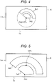
- the light (fan-shaped image) reflected from the fan-shaped upper hyperboloid mirror 102 and the lower hyperboloid mirror 103 can be received by the wider light-receiving surface of the image sensor 105, and as a result, the resolution of the stereo camera 101 can be improved. This will be described with reference to FIGS. 4 and 5 .
- FIG. 4 is an example of an image based on the first light R1 and the second light R2 formed on the light-receiving surface Pi of the image sensor 105 in a case where the center position CP1 substantially coincides with the optical axis Ox2.
- both a fan-shaped image Im1 based on the first light R1 and a fan-shaped image Im2 based on the second light R2 are formed mainly on one side (upper side in FIG. 4 ) of the center position CP1 and are not formed on the other side. For this reason, the number of pixels contributing to the analysis of the images Im1 and Im2 decreases, and a sufficient resolution cannot be obtained.
- FIG. 5 is an example of an image based on the first light R1 and the second light R2 formed on the light-receiving surface Pi of the image sensor 105 in a case where the center position CP1 is shifted from the optical axis Ox2.
- the fan-shaped images Im1 and Im2 can be received by the wide light-receiving surface of the image sensor 105 on both sides rather than one side of the center position CP1.
- the images Im1 and Im2 can be maximized on the light-receiving surface of the image sensor 105, and thereby the resolution of the stereo camera 101 can be improved.
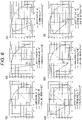
- FIGS. 6 and 7 illustrate an example of a relationship of between an aspect ratio AP of a light-receiving surface Pi of the image sensor 105, an internal angle ⁇ ( ⁇ 1, ⁇ 2) of the upper hyperboloid mirror 102 and the lower hyperboloid mirror 103, an angle ⁇ (hereinafter, referred to as "axial inclination ⁇ ") between a center line of the fan-shaped images Im1 and Im2 on the image sensor 105 and a short side Lx of the light-receiving surface of the image sensor 105, and a light receiving state of the light-receiving surface Pi of the image sensor 105.
- FIG. 6(a) illustrates an example of a simulation result of the light receiving state of the image sensor 105 in a case where the aspect ratio AP is set to 0.7, the internal angle ⁇ is set to 90°, the axial inclination ⁇ is set to 45.0°, and the magnification of the imaging optical system 104 is set to the maximum.
- FIGS. 6(b) to 6(f) also illustrate examples of simulation results of the light receiving state of the image sensor 105 in a case where the numerical values illustrated in FIG. 6 are set.
- FIG. 7 illustrates an example in a case where the aspect ratio AP is set to 0.75 (4:3) and 0.56 (16:9).
- the resolution of the stereo camera 101 can be further improved by setting the optimum axial inclination ⁇ according to the given aspect ratio AP and internal angle ⁇ .
- the image sensor 105 and the imaging optical system 104 are disposed such that center lines of the fan-shaped images Im1 and Im2 projected onto light-receiving surface Pi of the image sensor 105 are non-parallel to the short side Lx of the light-receiving surface Pi of the image sensor 105.
- the aspect ratio AP is 0.75
- the axial inclination ⁇ is preferably 25° or more if the internal angle ⁇ is 180° or less.
- the axial inclination ⁇ is preferably 7° or more if the internal angle ⁇ is 180° or less.
- FIG. 8 is a graph illustrating a combination of an internal angle ⁇ and an axial inclination ⁇ with which the resolution in the image sensor 105 can be maximized for each aspect ratio AP of the image sensor 105.
- the aspect ratio AP is 1, regardless of the magnitude of the internal angle ⁇ , the axial inclination ⁇ is optimally 45 degrees.
- the aspect ratio AP is less than 1, it is preferable that the larger the internal angle ⁇ , the smaller the axial inclination ⁇ .
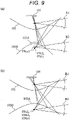
- FIG. 9(a) illustrates an example of the light receiving state of the first light R1 and the second light R2 when the inner hyperboloid mirror 103A protrudes upward as compared with the outer hyperboloid mirror 103B as in the present embodiment.
- FIG. 9 (b) illustrates an example of the light receiving state of the first light R1 and the second light R2 when there is no step between the inner hyperboloid mirror 103A and the outer hyperboloid mirror 103B unlike the present embodiment.
- the distance between the first focal point FPu1 and the first focal point FPdo1 is large.
- the distance between the light receiving positions of the first light R1 and the second light R2 is also large, and the angle of view that can be stereoscopically viewed is small.
- the distance between the light receiving positions of the first light R1 and the second light R2 can be reduced, and the angle of view that can be stereoscopically viewed can be increased.
- the resolution of the image sensor 105 can be improved, and the detection accuracy of the distance to the subject can be improved.
- hyperboloid mirrors arranged to face each other are used as a pair of mirrors that reflects light from the subject.
- the pair of mirrors is not limited to the hyperboloid mirrors as illustrated in the drawing, and a spherical mirror, a paraboloid mirror, an elliptical mirror, an aspherical mirror, or the like arranged opposite to each other can be adopted instead of the hyperboloid mirrors.
- the upper hyperboloid mirror 102 and the lower hyperboloid mirror 103 constituting the hyperboloid mirror are formed in a fan shape having the internal angle ⁇ of 180° or less. Furthermore, the center position of the image sensor 105 is set to a position shifted with respect to the optical axis of the imaging optical system so that the image from the fan-shaped hyperboloid mirror can be received to the maximum. With this, it is possible to provide a compact stereo camera capable of performing high-accuracy and wide-angle sensing.
- FIG. 10 a stereo camera 101 according to a second embodiment will be described with reference to FIG. 10 .
- the same components as those in FIG. 1 are denoted by the same reference numerals as those in FIG. 1 , and thus redundant description will be omitted.
- a reflection mirror 106 is provided between the imaging optical system 104 and the lower hyperboloid mirror 103. Furthermore, the arrangement position of the imaging optical system 104 is also the reflection direction of the reflection mirror 106, which is different from the first embodiment in which the imaging optical system 104 is disposed in the vicinity of the vertex of the hyperboloid of the upper hyperboloid mirror.
- the imaging optical system 104 and the image sensor 105 can be housed within the range of the height of the hyperboloid mirrors (the upper hyperboloid mirror 102 and the lower hyperboloid mirror 103), so that the size of the stereo camera 101 can be reduced.
- FIG. 11 is a perspective view illustrating a configuration example of a stereo camera-integrated headlight unit 800 according to the third embodiment.
- the stereo camera-integrated headlight unit 800 is obtained by integrating a stereo camera 101 similar to that of the above-described embodiment into a housing 804 of a headlight of an automobile.
- the stereo camera-integrated headlight unit 800 may incorporate a turn lamp, a positioning lamp, or the like.
- a configuration example of the stereo camera-integrated headlight unit 800 illustrated in FIG. 11 is assumed to be attached to left and right front ends of an automobile. On the left and right rear ends of the automobile, a tail lamp unit and a stop lamp unit similar to those in FIG. 11 can be provided.
- the stereo camera-integrated headlight unit 800 includes, as an example, an LED light source (not illustrated), a reflector 801 that reflects and focuses white light emitted from the LED light source toward the front of the automobile, a shade 802 that blocks the emitted light in order to form a cut-off line of a low beam, and a headlight structure (light irradiation unit) including a lens 803 that forms an image of an edge blocked by the shade 802 at a distance.
- the shade 802 can be made movable and shifted from the optical path.
- the stereo camera 101 and the headlight are integrated, an installation area can be reduced as compared with a case where the stereo camera 101 is disposed at the left and right front ends of the automobile separately from the headlight. Furthermore, handling is facilitated, and assembly and positioning with respect to the vehicle body can be easily performed. Furthermore, in the configuration example of FIG. 11 , in the headlight unit 800, the stereo camera 101 is disposed below the headlight structure (801 to 803). According to this disposition, since the stereo camera 101 can be disposed without blocking the light emitted from the headlight structure, so-called nose view can be easily realized in the automated driving vehicle.
- the present invention is not limited to the example of the above-described embodiment, and includes various modifications.
- examples of the above-described embodiments have been described in detail in order to describe the present invention in an easy-to-understand manner, and are not necessarily limited to those having all the described configurations.
- a part of a configuration of an example of an embodiment can be replaced with a configuration of another example.
- a configuration of another example can be added to a configuration of an example of an embodiment.
- some or all of the above-described configurations, functions, processing units, processing means, and the like may be realized by hardware, for example, by designing with an integrated circuit.
Landscapes
- Engineering & Computer Science (AREA)
- Multimedia (AREA)
- Physics & Mathematics (AREA)
- General Physics & Mathematics (AREA)
- Mechanical Engineering (AREA)
- Studio Devices (AREA)
- Measurement Of Optical Distance (AREA)
- Lenses (AREA)
- Stereoscopic And Panoramic Photography (AREA)
Abstract
Description
- The present invention relates to a stereo camera and a light unit with integrated stereo camera
- Development and improvement of automatic driving, automatic braking, automatic following, and the like in automobiles have been rapidly advanced. In order to realize fully automatic driving, it is necessary to accurately recognize an object moving at a high speed and measure a distance to the object in a wide range around the vehicle.
- For example, in a case where an object (for example, a motorcycle) moving at 70 km/h is recognized by a sensor at a front end of the vehicle, it is assumed that imaging with an angular resolution of 0.06°/pixel and a distance measurement system of 10% at a distance of 100m are necessary. Regarding such a requirement, existing laser imaging detection and ranging (LiDAR) and millimeter wave radars have a problem in that it is necessary to use a camera together for accurate recognition of the surroundings. In addition, in a case of a scanning type detection device, since a movable portion is required, there is a problem in that it is expensive and the response speed is not sufficient.
- In addition, a stereo camera capable of three-dimensionally grasping the position of an object is also used for automatic driving control and the like. However, in a case of a stereo camera in the related art, it is usually necessary to mount two image sensors apart from each other by an interval corresponding to parallax, which causes an increase in cost and an increase in size. Further, since the size is large, it is difficult to arrange it at the left and right front ends of the automobile, and also difficult to perform wide-angle sensing.
- As described above, in a case where a stereo camera is mounted on an automated driving vehicle, a compact stereo camera capable of performing high-accuracy and wide-angle sensing has been required.
- PTL 1:
Japanese Patent No. 4388530 - An object of the present invention is to provide a compact stereo camera and a light unit with integrated stereo camera capable of performing high-accuracy and wide-angle sensing.
- In order to solve the above problem, a stereo camera according to the present invention includes: a first mirror that has a first reflective surface which is a curved surface convex in a first direction, has a first vertex, and has a first fan shape; a second mirror that has a second reflective surface convex in a second direction opposite to the first direction, has a second vertex facing the first vertex, and has a second fan shape; an imaging optical system that forms an image of first light emitted from a subject, reflected on the first reflective surface, and then further reflected on the second reflective surface, and second light emitted from the subject and reflected on the second reflective surface; and an image sensor that receives the first light and the second light via the imaging optical system. The second mirror includes an outer mirror and an inner mirror located on an inner peripheral side of the outer mirror and having a conic constant different from a conic constant of the outer mirror. The image sensor is disposed at a position where a center position of the image sensor is shifted from an optical axis of the imaging optical system.
- According to the present invention, it is possible to provide a compact stereo camera and a headlight unit with integrated stereo camera capable of performing high-accuracy and wide-angle sensing.
-
- [
FIG. 1] FIG. 1 is a schematic perspective view illustrating an overall structure of astereo camera 101 according to a first embodiment. - [
FIG. 2] FIG. 2 is a schematic view illustrating structures and operations of anupper hyperboloid mirror 102 and a lower hyperboloid mirror 103 (inner hyperboloid mirror 103A andouter hyperboloid mirror 103B) in more detail. - [
FIG. 3] FIG. 3 is a schematic view illustrating a positional relationship between an imagingoptical system 104 and animage sensor 105. - [
FIG. 4] FIG. 4 is an example (comparative example) of an image based on a first light R1 and a second light R2 on a light-receiving surface Pi of theimage sensor 105 in a case where a center position CP1 substantially coincides with an optical axis Ox2. - [
FIG. 5] FIG. 5 is an example of an image based on the first light R1 and the second light R2 on the light-receiving surface Pi of theimage sensor 105 in a case where the center position CP1 is shifted from the optical axis Ox2. - [
FIG. 6] FIG. 6 illustrates an example of an aspect ratio of a light-receiving surface of theimage sensor 105, an internal angle θ (θ1, θ2) of theupper hyperboloid mirror 102 and thelower hyperboloid mirror 103, an angle α (hereinafter, referred to as "axial inclination α") between a center line of an image on the fan-shaped image sensor 105 and a vertical side (short side) of the light-receiving surface of theimage sensor 105, and a light receiving state of the light-receiving surface Pi of theimage sensor 105. - [
FIG. 7] FIG. 7 illustrates an example of an aspect ratio of a light-receiving surface of theimage sensor 105, an internal angle θ (θ1, θ2) of theupper hyperboloid mirror 102 and thelower hyperboloid mirror 103, an angle α (hereinafter, referred to as "axial inclination α") between a center line of an image on the fan-shaped image sensor 105 and a vertical side (short side) of the light-receiving surface of theimage sensor 105, and a light receiving state of the light-receiving surface Pi of theimage sensor 105. - [
FIG. 8] FIG. 8 is a graph illustrating a combination of an internal angle θ and an axial inclination α with which the resolution in theimage sensor 105 can be maximized for each aspect ratio AP of theimage sensor 105. - [
FIG. 9] FIG. 9 is a schematic view illustrating an effect that theinner hyperboloid mirror 103A and theouter hyperboloid mirror 103B have a step at a boundary therebetween. - [
FIG. 10] FIG. 10 is a schematic perspective view illustrating an overall structure of astereo camera 101 according to a second embodiment. - [
FIG. 11] FIG. 11 is a schematic perspective view illustrating a structure of a headlight set 800 according to a third embodiment. - Hereinafter, the present embodiment will be described with reference to the accompanying drawings. In the accompanying drawings, functionally same elements may be denoted by the same numbers. Note that, although the accompanying drawings illustrate embodiments and implementation examples conforming to the principles of the present disclosure, these are for understanding the present disclosure and are not used to interpret the present disclosure in a limited manner. The description herein is exemplary only and is not intended to limit the claims or applications of the disclosure in any way.
- In the present embodiment, the description has been made in sufficient detail for those skilled in the art to implement the present disclosure; however, it is necessary to understand that other implementations and embodiments are possible, and changes in configurations and structures and replacement of various elements are possible without departing from the scope and spirit of the technical idea of the present disclosure. Therefore, the following description should not be construed as limited to this.
- With reference to a schematic perspective view of
FIG. 1 , astereo camera 101 according to a first embodiment will be described with reference toFIG. 1 . As an example, thestereo camera 101 may include anupper hyperboloid mirror 102, alower hyperboloid mirror 103, an imagingoptical system 104, animage sensor 105, adisplay 117, and adrive control unit 118. One imagingoptical system 104 and oneimage sensor 105 may be provided for each of a pair of the hyperboloid mirrors (upper hyperboloid mirror 102 and lower hyperboloid mirror 103). Since the information on the position of the subject in a three-dimensional space can be grasped by thesingle image sensor 105, the cost can be reduced as compared with the stereo camera in the related art. - The upper hyperboloid mirror 102 (first mirror) and the lower hyperboloid mirror 103 (second mirror) integrally constitute a hyperboloid mirror. The
upper hyperboloid mirror 102 has a reflective surface (first reflective surface) along an upper hyperboloid convex in a downward direction (negative direction of the Z-axis (first direction)), while the lower hyperboloid mirror has a reflective surface (second reflective surface) along a lower hyperboloid convex in an upward direction (positive direction of the Z-axis (second direction)). In other words, theupper hyperboloid mirror 102 and thelower hyperboloid mirror 103 are arranged such that the vertex of theupper hyperboloid mirror 102 and the vertex of thelower hyperboloid mirror 103 face each other and the central axis Ox coincides with each other. Note that a Z direction inFIG. 1 is typically preferably a direction substantially coinciding with the gravity direction in a case where thestereo camera 101 is mounted on an automobile, but is not limited thereto. In the example ofFIG. 1 , theupper hyperboloid mirror 102 is disposed on the upper side and thelower hyperboloid mirror 103 is disposed on the lower side, but the vertical positional relationship can be reversed. - The
lower hyperboloid mirror 103 is further divided into aninner hyperboloid mirror 103A (inner mirror) and anouter hyperboloid mirror 103B (outer mirror). Theinner hyperboloid mirror 103A is disposed at a position including the vertex of the hyperboloid, and theouter hyperboloid mirror 103B is disposed on the outer peripheral side of the outer edge of theinner hyperboloid mirror 103. Theinner hyperboloid mirror 103 and theouter hyperboloid mirror 103B have a common central axis Ox. Theinner hyperboloid mirror 103A and theouter hyperboloid mirror 103B have different conic constants. Further, both have a step at the boundary, and theinner hyperboloid mirror 103A protrudes upward from theouter hyperboloid mirror 103B. - The
upper hyperboloid mirror 102 does not have a reflective surface over the entire circumference (360°) of the hyperboloid surface, and is cut out in a fan shape (first fan shape) having an internal angle θ1 of 90° or more and 180° or less. Similarly, thelower hyperboloid mirror 103 does not have a reflective surface over the entire circumference (360°) of the hyperboloid surface, and is cut out in a fan shape (second fan shape) having an internal angle θ2 of 90° or more and 180° or less. The internal angles θ1 and θ2 are set to angles corresponding to a horizontal view angle of thestereo camera 101. - Since the
upper hyperboloid mirror 102 and thelower hyperboloid mirror 103 have such fan shapes, the resolution of theimage sensor 105 can be improved, and as a result, the accuracy of the distance measurement of the stereo camera can be improved. This point will be described later. The fan shape described herein is not limited to a shape obtained by linearly cutting out a part of a circle along a radius thereof. For example, as illustrated inFIG. 1 , a shape in which a reflective surface in the vicinity of the vertex is cut out is also included in the fan shape described herein. In the following description, it is assumed that the internal angles θ1 and θ2 have the same value, but the internal angles θ1 and θ2 may have different values. - The
stereo camera 101 reflects a plurality of light fluxes having different paths from the subject on a hyperboloid mirror (theupper hyperboloid mirror 102 and the lower hyperboloid mirror 103) in a range of a predetermined horizontal angle of view, thereby making it possible to acquire information on the distance to the subject. Specifically, the first light R1 from the subject is reflected by theupper hyperboloid mirror 102, then further reflected on the lower hyperboloid mirror 103 (theinner hyperboloid mirror 103A), and then incident on theimage sensor 105 via the imagingoptical system 104. In addition, the second light R2 different from the first light R1 from the subject is reflected on the lower hyperboloid mirror 103 (theouter hyperboloid mirror 103B) and is incident on theimage sensor 105 via the imagingoptical system 104. In this manner, the first light R1 and the second light R2, which pass through different optical paths from the subject and reach the hyperboloid mirror, are incident on different portions on theimage sensor 105 from different directions, and thereby the three-dimensional position and distance of the subject can be calculated. - The imaging
optical system 104 is configured to include a combination of one or more lenses, and can be preferably disposed on a straight line connecting the vertexes of theupper hyperboloid mirror 102 and thelower hyperboloid mirror 103. - The
image sensor 105 includes, for example, a complementary metal oxide semiconductor (CMOS) sensor or a charge coupled device (CCD) sensor, and is configured to generate an image signal based on light received via the imagingoptical system 104 and output the image signal to thedrive control unit 118 under the control of thedrive control unit 118. - The
drive control unit 118 supplies the image signal output from theimage sensor 105 to thedisplay 117. Thedisplay 117 generates three-dimensional position information of a subject 109 based on the supplied output image. Specifically, thedrive control unit 118 calculates the three-dimensional position or distance of the subject by analyzing the image signal based on the first light R1 and the second light R2. Note that the image itself received by theimage sensor 105 may be displayed on thedisplay 117, or a three-dimensional image of the subject as a result of performing predetermined image processing may be displayed. The three-dimensional image information may be displayed on thedisplay 117, may be supplied to an electronic control unit (ECU) of an automobile on which thestereo camera 101 is mounted, or may be transmitted to an external server via a communication control unit (not illustrated). - Next, the
upper hyperboloid mirror 102 and the lower hyperboloid mirror 103 (inner hyperboloid mirror 103A andouter hyperboloid mirror 103B) will be described in more detail with reference toFIG. 2 . - The hyperboloid of each of the
upper hyperboloid mirror 102, theinner hyperboloid mirror 103A, and theouter hyperboloid mirror 103B can be defined by a quadratic surface expressed by the following [Mathematical Formula 1]. When the conic constant κ is smaller than -1, the quadratic surface becomes a hyperboloid. The absolute value of the conic constant κ of theinner hyperboloid mirror 103A is set to a value larger than the absolute value of the conic constant κ of theouter hyperboloid mirror 103B.
- Here, z(r) in [Mathematical Formula 1] is the sag amount of the surface in the optical axis direction with the vertex on the optical axis as an origin. c represents curvature on the optical axis (on-axis curvature), and r represents a radial coordinate from the optical axis.
- In general, a hyperboloid has two focal points, and the coordinates thereof are expressed by the following equation [Mathematical Formula 2] with respect to a surface vertex.

- Note that the coordinates of the focal point on the inner side of the hyperboloid are represented by f when ± of [Mathematical Formula 2] is +. Furthermore, in [Mathematical Formula 2], the coordinates of the focal point on the outer side of the hyperboloid are represented by f in a case where ± is -. Hereinafter, a focal point on the inner side of the hyperboloid is referred to as a "first focal point", and a focal point on the outer side of the hyperboloid is referred to as a "second focal point".
- The
upper hyperboloid mirror 102 and theinner hyperboloid mirror 103A are arranged such that a second focal point FPu2 of theupper hyperboloid mirror 102 substantially coincides with a first focal point FPdi1 of theinner hyperboloid mirror 103A. Note that a first focal point FPdo1 of theouter hyperboloid mirror 103B does not need to substantially coincide with the second focal point FPu2 and the first focal point FPdi1, but theouter hyperboloid mirror 103B is preferably disposed so as to be in the vicinity thereof. - The
inner hyperboloid mirror 103A and theouter hyperboloid mirror 103B are arranged such that a second focal point FPdo2 of theouter hyperboloid mirror 103B substantially coincides with a second focal point FPdi2 of theinner hyperboloid mirror 103A. The imagingoptical system 104 is disposed at the positions of the second focal point FPdo2 and the second focal point FPdi2. Note that a first focal point FPu1 of theupper hyperboloid mirror 102 may substantially coincide with the positions of the second focal point FPdo2 and the second focal point FPdi2, but is preferably located in the vicinity thereof, specifically, above the positions of the second focal point FPdo2 and the second focal point FPdi2. - Since the
upper hyperboloid mirror 102 and thelower hyperboloid mirror 103 have the above positional relationship, the first light R1 directed from the subject to the first focal point FPu1 is reflected by theupper hyperboloid mirror 102 and then directed to the second focal point FPu2. Since the second focal point FPu2 and the first focal point FPdi1 substantially coincide with each other, the light reflected by theinner hyperboloid mirror 103A is condensed toward the second focal point FPdi2 (second focal point FPdo2). This light is incident on theimage sensor 105 via the imagingoptical system 104. - The second light R2 directed from the subject to the first focal point FPdo1 is reflected by the
outer hyperboloid mirror 103B and then directed to the second focal point FPdo2 (second focal point FPdi2). The second light R2 is incident on the imagingoptical system 104 at an incident angle different from that of the first light R1, and thereby the second light is incident on a light-receiving surface of theimage sensor 105 at a position different from that of the first light R1. - As described above, the
image sensor 105 captures the image of the subject viewed from the first focal point 1021 based on the first light R1, and projects the image of the subject viewed from the first focal point FPdo1 based on the second light R2, and these images are used as output images. As described above, the absolute value of the conic constant κ of theinner hyperboloid mirror 103A is set to a value larger than the absolute value of the conic constant κ of theouter hyperboloid mirror 103B. As a result, in the output image of theimage sensor 105, the sizes of the image of the subject viewed from the first focal point (upper viewpoint) FPu1 and the image of the subject viewed from the first focal point FPdo1 are aligned. Since the sizes of the images are aligned, the resolutions of both images can be matched, and the accuracy of the parallax matching processing can be improved. - Next, a positional relationship between the imaging
optical system 104 and theimage sensor 105 will be described with reference toFIG. 3 . The optical axis Ox2 of the imagingoptical system 104 is disposed so as to coincide with the central axes Ox of theupper hyperboloid mirror 102 and thelower hyperboloid mirror 103. On the other hand, the center position CP1 of the light-receiving surface Pi of theimage sensor 105 is shifted from the optical axis Ox2. As a result, the light (fan-shaped image) reflected from the fan-shapedupper hyperboloid mirror 102 and thelower hyperboloid mirror 103 can be received by the wider light-receiving surface of theimage sensor 105, and as a result, the resolution of thestereo camera 101 can be improved. This will be described with reference toFIGS. 4 and 5 . -
FIG. 4 is an example of an image based on the first light R1 and the second light R2 formed on the light-receiving surface Pi of theimage sensor 105 in a case where the center position CP1 substantially coincides with the optical axis Ox2. In this case, both a fan-shaped image Im1 based on the first light R1 and a fan-shaped image Im2 based on the second light R2 are formed mainly on one side (upper side inFIG. 4 ) of the center position CP1 and are not formed on the other side. For this reason, the number of pixels contributing to the analysis of the images Im1 and Im2 decreases, and a sufficient resolution cannot be obtained. - On the other hand,
FIG. 5 is an example of an image based on the first light R1 and the second light R2 formed on the light-receiving surface Pi of theimage sensor 105 in a case where the center position CP1 is shifted from the optical axis Ox2. Unlike the case ofFIG. 4 , the fan-shaped images Im1 and Im2 can be received by the wide light-receiving surface of theimage sensor 105 on both sides rather than one side of the center position CP1. By appropriately setting the magnification of the imagingoptical system 104 and a shift amount (FIG. 3 ) of theimage sensor 105, the images Im1 and Im2 can be maximized on the light-receiving surface of theimage sensor 105, and thereby the resolution of thestereo camera 101 can be improved. -
FIGS. 6 and7 illustrate an example of a relationship of between an aspect ratio AP of a light-receiving surface Pi of theimage sensor 105, an internal angle θ (θ1, θ2) of theupper hyperboloid mirror 102 and thelower hyperboloid mirror 103, an angle α (hereinafter, referred to as "axial inclination α") between a center line of the fan-shaped images Im1 and Im2 on theimage sensor 105 and a short side Lx of the light-receiving surface of theimage sensor 105, and a light receiving state of the light-receiving surface Pi of theimage sensor 105. Here, the internal angle θ1 = θ2 is assumed. -
FIG. 6(a) illustrates an example of a simulation result of the light receiving state of theimage sensor 105 in a case where the aspect ratio AP is set to 0.7, the internal angle θ is set to 90°, the axial inclination α is set to 45.0°, and the magnification of the imagingoptical system 104 is set to the maximum.FIGS. 6(b) to 6(f) also illustrate examples of simulation results of the light receiving state of theimage sensor 105 in a case where the numerical values illustrated inFIG. 6 are set.FIG. 7 illustrates an example in a case where the aspect ratio AP is set to 0.75 (4:3) and 0.56 (16:9). - As is clear from
FIGS. 6 and7 , the resolution of thestereo camera 101 can be further improved by setting the optimum axial inclination α according to the given aspect ratio AP and internal angle θ. Theimage sensor 105 and the imagingoptical system 104 are disposed such that center lines of the fan-shaped images Im1 and Im2 projected onto light-receiving surface Pi of theimage sensor 105 are non-parallel to the short side Lx of the light-receiving surface Pi of theimage sensor 105. As a result of simulations by the applicant includingFIGS. 6 and7 , it has been found that when the aspect ratio AP is 0.75, the axial inclination α is preferably 25° or more if the internal angle θ is 180° or less. In addition, it has been found that when the aspect ratio AP is 0.56 (16:9), the axial inclination α is preferably 7° or more if the internal angle θ is 180° or less. -
FIG. 8 is a graph illustrating a combination of an internal angle θ and an axial inclination α with which the resolution in theimage sensor 105 can be maximized for each aspect ratio AP of theimage sensor 105. As illustrated inFIG. 8 , when the aspect ratio AP is 1, regardless of the magnitude of the internal angle θ, the axial inclination α is optimally 45 degrees. However, in a case where the aspect ratio AP is less than 1, it is preferable that the larger the internal angle θ, the smaller the axial inclination α. - As described above, it is preferable that the
inner hyperboloid mirror 103A and theouter hyperboloid mirror 103B have a step at the boundary, and theinner hyperboloid mirror 103A protrudes upward as compared with theouter hyperboloid mirror 103B.FIG. 9(a) illustrates an example of the light receiving state of the first light R1 and the second light R2 when theinner hyperboloid mirror 103A protrudes upward as compared with theouter hyperboloid mirror 103B as in the present embodiment. On the other hand,FIG. 9 (b) illustrates an example of the light receiving state of the first light R1 and the second light R2 when there is no step between theinner hyperboloid mirror 103A and theouter hyperboloid mirror 103B unlike the present embodiment. - In the case of
FIG. 9(b) , the distance between the first focal point FPu1 and the first focal point FPdo1 is large. With this, in theimage sensor 105, the distance between the light receiving positions of the first light R1 and the second light R2 is also large, and the angle of view that can be stereoscopically viewed is small. In this regard, in the first embodiment (FIG. 9(a) ), the distance between the light receiving positions of the first light R1 and the second light R2 can be reduced, and the angle of view that can be stereoscopically viewed can be increased. Alternatively, the resolution of theimage sensor 105 can be improved, and the detection accuracy of the distance to the subject can be improved. - In the first embodiment described above, hyperboloid mirrors arranged to face each other are used as a pair of mirrors that reflects light from the subject. However, the pair of mirrors is not limited to the hyperboloid mirrors as illustrated in the drawing, and a spherical mirror, a paraboloid mirror, an elliptical mirror, an aspherical mirror, or the like arranged opposite to each other can be adopted instead of the hyperboloid mirrors.
- As described above, in the
stereo camera 101 of the first embodiment, theupper hyperboloid mirror 102 and thelower hyperboloid mirror 103 constituting the hyperboloid mirror are formed in a fan shape having the internal angle θ of 180° or less. Furthermore, the center position of theimage sensor 105 is set to a position shifted with respect to the optical axis of the imaging optical system so that the image from the fan-shaped hyperboloid mirror can be received to the maximum. With this, it is possible to provide a compact stereo camera capable of performing high-accuracy and wide-angle sensing. - Next, a
stereo camera 101 according to a second embodiment will be described with reference toFIG. 10 . InFIG. 10 , the same components as those inFIG. 1 are denoted by the same reference numerals as those inFIG. 1 , and thus redundant description will be omitted. - In the second embodiment, a reflection mirror 106 is provided between the imaging
optical system 104 and thelower hyperboloid mirror 103. Furthermore, the arrangement position of the imagingoptical system 104 is also the reflection direction of the reflection mirror 106, which is different from the first embodiment in which the imagingoptical system 104 is disposed in the vicinity of the vertex of the hyperboloid of the upper hyperboloid mirror. - According to this configuration, since the incident light to the imaging
optical system 104 can be folded back by the reflection mirror 106, the imagingoptical system 104 and theimage sensor 105 can be housed within the range of the height of the hyperboloid mirrors (theupper hyperboloid mirror 102 and the lower hyperboloid mirror 103), so that the size of thestereo camera 101 can be reduced. - Next, a stereo camera-integrated headlight unit according to a third embodiment will be described with reference to
FIG. 11. FIG. 11 is a perspective view illustrating a configuration example of a stereo camera-integratedheadlight unit 800 according to the third embodiment. - The stereo camera-integrated
headlight unit 800 is obtained by integrating astereo camera 101 similar to that of the above-described embodiment into ahousing 804 of a headlight of an automobile. The stereo camera-integratedheadlight unit 800 may incorporate a turn lamp, a positioning lamp, or the like. - Note that a configuration example of the stereo camera-integrated
headlight unit 800 illustrated inFIG. 11 is assumed to be attached to left and right front ends of an automobile. On the left and right rear ends of the automobile, a tail lamp unit and a stop lamp unit similar to those inFIG. 11 can be provided. - The stereo camera-integrated
headlight unit 800 includes, as an example, an LED light source (not illustrated), areflector 801 that reflects and focuses white light emitted from the LED light source toward the front of the automobile, ashade 802 that blocks the emitted light in order to form a cut-off line of a low beam, and a headlight structure (light irradiation unit) including alens 803 that forms an image of an edge blocked by theshade 802 at a distance. Note that, in a case of emitting a high beam, for example, theshade 802 can be made movable and shifted from the optical path. - According to the stereo camera-integrated
headlight unit 800 in which thestereo camera 101 and the headlight are integrated, an installation area can be reduced as compared with a case where thestereo camera 101 is disposed at the left and right front ends of the automobile separately from the headlight. Furthermore, handling is facilitated, and assembly and positioning with respect to the vehicle body can be easily performed. Furthermore, in the configuration example ofFIG. 11 , in theheadlight unit 800, thestereo camera 101 is disposed below the headlight structure (801 to 803). According to this disposition, since thestereo camera 101 can be disposed without blocking the light emitted from the headlight structure, so-called nose view can be easily realized in the automated driving vehicle. - Although the respective embodiments and modifications according to the present invention have been described above, the present invention is not limited to the example of the above-described embodiment, and includes various modifications. For example, examples of the above-described embodiments have been described in detail in order to describe the present invention in an easy-to-understand manner, and are not necessarily limited to those having all the described configurations. In addition, a part of a configuration of an example of an embodiment can be replaced with a configuration of another example. In addition, a configuration of another example can be added to a configuration of an example of an embodiment. Furthermore, it is possible to add, delete, and replace other configurations for a part of the configuration of each embodiment. In addition, some or all of the above-described configurations, functions, processing units, processing means, and the like may be realized by hardware, for example, by designing with an integrated circuit.
-
- 101
- stereo camera
- 102
- upper hyperboloid mirror
- 103
- lower hyperboloid mirror
- 103A
- inner hyperboloid mirror
- 104
- imaging optical system
- 105
- image sensor
- 117
- display
- 118
- drive control unit
Claims (13)
- A stereo camera comprising:a first mirror that has a first reflective surface which is a curved surface convex in a first direction, has a first vertex, and has a first fan shape;a second mirror that has a second reflective surface convex in a second direction opposite to the first direction, has a second vertex facing the first vertex, and has a second fan shape;an imaging optical system that forms an image of first light emitted from a subject, reflected on the first reflective surface, and then further reflected on the second reflective surface, and second light emitted from the subject and reflected on the second reflective surface; andan image sensor that receives the first light and the second light via the imaging optical system,whereinthe second mirror includes an inner mirror and an outer mirror located on an outer peripheral side of the inner mirror and having a conic constant different from a conic constant of the inner mirror, andthe image sensor is disposed at a position where a center position of the image sensor is shifted from an optical axis of the imaging optical system.
- The stereo camera according to claim 1, whereinthe first light is light that is directed to a first focal point of the first mirror and is reflected on the first reflective surface, and further that is directed to a first focal point of the inner mirror and is reflected on the second reflective surface, andthe second light is light that is directed to a first focal point of the outer mirror and is reflected on the second reflective surface.
- The stereo camera according to claim 1, wherein the first mirror and the second mirror are disposed such that a second focal point of the first mirror substantially coincides with the first focal point of the inner mirror.
- The stereo camera according to claim 3, wherein the inner mirror and the outer mirror are disposed such that a second focal point of the inner mirror substantially coincides with a second focal point of the outer mirror.
- The stereo camera according to claim 1, wherein the image sensor and the imaging optical system are disposed such that a center line of a fan-shaped image projected on a light-receiving surface of the image sensor is non-parallel to a short side of the light-receiving surface of the image sensor.
- The stereo camera according to claim 1, further comprising:
a mirror disposed to reflect the first light or the second light toward the imaging optical system. - The stereo camera according to claim 1, wherein the outer mirror has a step with an outer periphery of the inner mirror.
- A light unit with integrated stereo camera, comprising:a stereo camera; anda light irradiation unit that emits light emitted from a light source,whereinthe stereo camera includes:a first mirror that has a first reflective surface which is a curved surface convex in a first direction, has a first vertex, and has a first fan shape;a second mirror that has a second reflective surface convex in a second direction opposite to the first direction, has a second vertex facing the first vertex, and has a second fan shape;an imaging optical system that forms an image of first light emitted from a subject, reflected on the first reflective surface, and then further reflected on the second reflective surface, and second light emitted from the subject and reflected on the second reflective surface; andan image sensor that receives the first light and the second light via the imaging optical system,the second mirror includes an inner mirror and an outer mirror located on an outer peripheral side of the inner mirror and having a conic constant different from a conic constant of the inner mirror, andthe image sensor is disposed at a position where a center position of the image sensor is shifted from an optical axis of the imaging optical system.
- The light unit with integrated stereo camera according to claim 8, wherein the stereo camera is disposed below the light irradiation unit.
- The light unit with integrated stereo camera according to claim 8, whereinthe first light is light that is directed to a first focal point of the first mirror and is reflected on the first reflective surface, and further that is directed to a first focal point of the inner mirror and is reflected on the second reflective surface, andthe second light is light that is directed to a first focal point of the outer mirror and is reflected on the second reflective surface.
- The light unit with integrated stereo camera according to claim 8, wherein the first mirror and the second mirror are disposed such that a second focal point of the first mirror substantially coincides with the first focal point of the inner mirror.
- The light unit with integrated stereo camera according to claim 11, wherein the inner mirror and the outer mirror are arranged such that a second focal point of the inner mirror substantially coincides with a second focal point of the outer mirror.
- The light unit with integrated stereo camera according to claim 8, wherein the image sensor and the imaging optical system are disposed such that a center line of a fan-shaped image projected on a light-receiving surface of the image sensor is non-parallel to a short side of the light-receiving surface of the image sensor.
Applications Claiming Priority (2)
| Application Number | Priority Date | Filing Date | Title |
|---|---|---|---|
| JP2019125737A JP7264749B2 (en) | 2019-07-05 | 2019-07-05 | Stereo camera and stereo camera integrated light unit |
| PCT/JP2020/021765 WO2021005921A1 (en) | 2019-07-05 | 2020-06-02 | Stereo camera and light unit with integrated stereo camera |
Publications (3)
| Publication Number | Publication Date |
|---|---|
| EP3995888A1 true EP3995888A1 (en) | 2022-05-11 |
| EP3995888A4 EP3995888A4 (en) | 2023-07-12 |
| EP3995888B1 EP3995888B1 (en) | 2025-07-23 |
Family
ID=74113946
Family Applications (1)
| Application Number | Title | Priority Date | Filing Date |
|---|---|---|---|
| EP20837915.6A Active EP3995888B1 (en) | 2019-07-05 | 2020-06-02 | Stereo camera and light unit with integrated stereo camera |
Country Status (3)
| Country | Link |
|---|---|
| EP (1) | EP3995888B1 (en) |
| JP (1) | JP7264749B2 (en) |
| WO (1) | WO2021005921A1 (en) |
Family Cites Families (7)
| Publication number | Priority date | Publication date | Assignee | Title |
|---|---|---|---|---|
| JP2002196438A (en) * | 2000-10-20 | 2002-07-12 | Matsushita Electric Ind Co Ltd | Wide-angle imaging device |
| JP2002185957A (en) * | 2000-12-12 | 2002-06-28 | Nippon Lsi Card Co Ltd | Surrounding visual feature detection method, half-circle camera, and surrounding monitoring system for moving object |
| KR100715026B1 (en) * | 2005-05-26 | 2007-05-09 | 한국과학기술원 | Single camera omnidirectional binocular image acquisition device |
| JP2008243515A (en) * | 2007-03-27 | 2008-10-09 | Clarion Co Ltd | Vehicle-integrated light unit for vehicles |
| CN102053475A (en) * | 2010-10-15 | 2011-05-11 | 肖继忠 | Single camera based omnibearing stereo vision system |
| JP5459560B2 (en) * | 2011-06-27 | 2014-04-02 | アイシン精機株式会社 | Perimeter monitoring device |
| JP5846872B2 (en) * | 2011-11-21 | 2016-01-20 | 日立オートモティブシステムズ株式会社 | Image processing device |
-
2019
- 2019-07-05 JP JP2019125737A patent/JP7264749B2/en active Active
-
2020
- 2020-06-02 WO PCT/JP2020/021765 patent/WO2021005921A1/en not_active Ceased
- 2020-06-02 EP EP20837915.6A patent/EP3995888B1/en active Active
Also Published As
| Publication number | Publication date |
|---|---|
| JP2021012074A (en) | 2021-02-04 |
| EP3995888A4 (en) | 2023-07-12 |
| WO2021005921A1 (en) | 2021-01-14 |
| EP3995888B1 (en) | 2025-07-23 |
| JP7264749B2 (en) | 2023-04-25 |
Similar Documents
| Publication | Publication Date | Title |
|---|---|---|
| US10761406B2 (en) | Optical system, image capturing apparatus, distance measuring apparatus, and vehicle-mounted system | |
| EP3404911A1 (en) | Imaging system and moving body control system | |
| CN109855594A (en) | Photographic device, distance measuring equipment, onboard system and mobile device | |
| US11405600B2 (en) | Stereo camera | |
| JP6661955B2 (en) | Display device | |
| EP3995888B1 (en) | Stereo camera and light unit with integrated stereo camera | |
| JP7575636B1 (en) | Imaging device | |
| JP6983740B2 (en) | Stereo camera system and distance measurement method | |
| US20230156361A1 (en) | Surround-View Imaging System | |
| CN112219086B (en) | Stereo cameras, vehicle lighting assemblies, and stereo camera systems | |
| JP7346080B2 (en) | Stereo camera system and distance measurement method | |
| Mäyrä et al. | Fisheye optics for omnidirectional perception | |
| CN115668108A (en) | Viewpoint detection device and display device | |
| US12610113B2 (en) | Imaging apparatus | |
| JP2004139288A (en) | Optical coordinate input device | |
| JP2019028128A (en) | Optical system, imaging apparatus and projection apparatus including the same | |
| EP2139224A1 (en) | Imaging system, sensor unit with an imaging system and vehicle mirror comprising an imaging system | |
| CN119769099A (en) | Video camera system | |
| CN115668031A (en) | Image display module | |
| JP2020052426A (en) | Display device, vehicle | |
| JP2019090995A (en) | Optical system, imaging device, distance measuring device, and on-vehicle camera system | |
| JP2004354436A (en) | Stereoscopic imaging apparatus |
Legal Events
| Date | Code | Title | Description |
|---|---|---|---|
| STAA | Information on the status of an ep patent application or granted ep patent |
Free format text: STATUS: THE INTERNATIONAL PUBLICATION HAS BEEN MADE |
|
| PUAI | Public reference made under article 153(3) epc to a published international application that has entered the european phase |
Free format text: ORIGINAL CODE: 0009012 |
|
| STAA | Information on the status of an ep patent application or granted ep patent |
Free format text: STATUS: REQUEST FOR EXAMINATION WAS MADE |
|
| 17P | Request for examination filed |
Effective date: 20211210 |
|
| AK | Designated contracting states |
Kind code of ref document: A1 Designated state(s): AL AT BE BG CH CY CZ DE DK EE ES FI FR GB GR HR HU IE IS IT LI LT LU LV MC MK MT NL NO PL PT RO RS SE SI SK SM TR |
|
| DAV | Request for validation of the european patent (deleted) | ||
| DAX | Request for extension of the european patent (deleted) | ||
| REG | Reference to a national code |
Ipc: G03B0037060000 Ref country code: DE Ref legal event code: R079 Ref document number: 602020055153 Country of ref document: DE Free format text: PREVIOUS MAIN CLASS: G03B0015000000 Ipc: G03B0037060000 |
|
| A4 | Supplementary search report drawn up and despatched |
Effective date: 20230612 |
|
| RIC1 | Information provided on ipc code assigned before grant |
Ipc: B60R 1/31 20220101ALI20230605BHEP Ipc: B60R 1/24 20220101ALI20230605BHEP Ipc: H04N 23/55 20230101ALI20230605BHEP Ipc: G03B 29/00 20210101ALI20230605BHEP Ipc: G03B 17/17 20210101ALI20230605BHEP Ipc: G03B 35/10 20210101ALI20230605BHEP Ipc: G03B 37/06 20210101AFI20230605BHEP |
|
| GRAP | Despatch of communication of intention to grant a patent |
Free format text: ORIGINAL CODE: EPIDOSNIGR1 |
|
| STAA | Information on the status of an ep patent application or granted ep patent |
Free format text: STATUS: GRANT OF PATENT IS INTENDED |
|
| INTG | Intention to grant announced |
Effective date: 20250303 |
|
| GRAS | Grant fee paid |
Free format text: ORIGINAL CODE: EPIDOSNIGR3 |
|
| GRAA | (expected) grant |
Free format text: ORIGINAL CODE: 0009210 |
|
| STAA | Information on the status of an ep patent application or granted ep patent |
Free format text: STATUS: THE PATENT HAS BEEN GRANTED |
|
| AK | Designated contracting states |
Kind code of ref document: B1 Designated state(s): AL AT BE BG CH CY CZ DE DK EE ES FI FR GB GR HR HU IE IS IT LI LT LU LV MC MK MT NL NO PL PT RO RS SE SI SK SM TR |
|
| REG | Reference to a national code |
Ref country code: GB Ref legal event code: FG4D |
|
| REG | Reference to a national code |
Ref country code: CH Ref legal event code: EP |
|
| REG | Reference to a national code |
Ref country code: DE Ref legal event code: R096 Ref document number: 602020055153 Country of ref document: DE |
|
| REG | Reference to a national code |
Ref country code: IE Ref legal event code: FG4D |
|
| REG | Reference to a national code |
Ref country code: NL Ref legal event code: MP Effective date: 20250723 |
|
| PG25 | Lapsed in a contracting state [announced via postgrant information from national office to epo] |
Ref country code: PT Free format text: LAPSE BECAUSE OF FAILURE TO SUBMIT A TRANSLATION OF THE DESCRIPTION OR TO PAY THE FEE WITHIN THE PRESCRIBED TIME-LIMIT Effective date: 20251124 |
|
| PG25 | Lapsed in a contracting state [announced via postgrant information from national office to epo] |
Ref country code: NL Free format text: LAPSE BECAUSE OF FAILURE TO SUBMIT A TRANSLATION OF THE DESCRIPTION OR TO PAY THE FEE WITHIN THE PRESCRIBED TIME-LIMIT Effective date: 20250723 |
|
| REG | Reference to a national code |
Ref country code: AT Ref legal event code: MK05 Ref document number: 1817019 Country of ref document: AT Kind code of ref document: T Effective date: 20250723 |
|
| PG25 | Lapsed in a contracting state [announced via postgrant information from national office to epo] |
Ref country code: IS Free format text: LAPSE BECAUSE OF FAILURE TO SUBMIT A TRANSLATION OF THE DESCRIPTION OR TO PAY THE FEE WITHIN THE PRESCRIBED TIME-LIMIT Effective date: 20251123 |
|
| PG25 | Lapsed in a contracting state [announced via postgrant information from national office to epo] |
Ref country code: NO Free format text: LAPSE BECAUSE OF FAILURE TO SUBMIT A TRANSLATION OF THE DESCRIPTION OR TO PAY THE FEE WITHIN THE PRESCRIBED TIME-LIMIT Effective date: 20251023 |
|
| REG | Reference to a national code |
Ref country code: LT Ref legal event code: MG9D |
|
| PG25 | Lapsed in a contracting state [announced via postgrant information from national office to epo] |
Ref country code: AT Free format text: LAPSE BECAUSE OF FAILURE TO SUBMIT A TRANSLATION OF THE DESCRIPTION OR TO PAY THE FEE WITHIN THE PRESCRIBED TIME-LIMIT Effective date: 20250723 |
|
| PG25 | Lapsed in a contracting state [announced via postgrant information from national office to epo] |
Ref country code: FI Free format text: LAPSE BECAUSE OF FAILURE TO SUBMIT A TRANSLATION OF THE DESCRIPTION OR TO PAY THE FEE WITHIN THE PRESCRIBED TIME-LIMIT Effective date: 20250723 |
|
| PG25 | Lapsed in a contracting state [announced via postgrant information from national office to epo] |
Ref country code: HR Free format text: LAPSE BECAUSE OF FAILURE TO SUBMIT A TRANSLATION OF THE DESCRIPTION OR TO PAY THE FEE WITHIN THE PRESCRIBED TIME-LIMIT Effective date: 20250723 |
|
| PG25 | Lapsed in a contracting state [announced via postgrant information from national office to epo] |
Ref country code: GR Free format text: LAPSE BECAUSE OF FAILURE TO SUBMIT A TRANSLATION OF THE DESCRIPTION OR TO PAY THE FEE WITHIN THE PRESCRIBED TIME-LIMIT Effective date: 20251024 |
|
| PG25 | Lapsed in a contracting state [announced via postgrant information from national office to epo] |
Ref country code: SE Free format text: LAPSE BECAUSE OF FAILURE TO SUBMIT A TRANSLATION OF THE DESCRIPTION OR TO PAY THE FEE WITHIN THE PRESCRIBED TIME-LIMIT Effective date: 20250723 |
|
| PG25 | Lapsed in a contracting state [announced via postgrant information from national office to epo] |
Ref country code: LV Free format text: LAPSE BECAUSE OF FAILURE TO SUBMIT A TRANSLATION OF THE DESCRIPTION OR TO PAY THE FEE WITHIN THE PRESCRIBED TIME-LIMIT Effective date: 20250723 |
|
| PG25 | Lapsed in a contracting state [announced via postgrant information from national office to epo] |
Ref country code: BG Free format text: LAPSE BECAUSE OF FAILURE TO SUBMIT A TRANSLATION OF THE DESCRIPTION OR TO PAY THE FEE WITHIN THE PRESCRIBED TIME-LIMIT Effective date: 20250723 Ref country code: PL Free format text: LAPSE BECAUSE OF FAILURE TO SUBMIT A TRANSLATION OF THE DESCRIPTION OR TO PAY THE FEE WITHIN THE PRESCRIBED TIME-LIMIT Effective date: 20250723 |
|
| PG25 | Lapsed in a contracting state [announced via postgrant information from national office to epo] |
Ref country code: RS Free format text: LAPSE BECAUSE OF FAILURE TO SUBMIT A TRANSLATION OF THE DESCRIPTION OR TO PAY THE FEE WITHIN THE PRESCRIBED TIME-LIMIT Effective date: 20251023 |
|
| PG25 | Lapsed in a contracting state [announced via postgrant information from national office to epo] |
Ref country code: ES Free format text: LAPSE BECAUSE OF FAILURE TO SUBMIT A TRANSLATION OF THE DESCRIPTION OR TO PAY THE FEE WITHIN THE PRESCRIBED TIME-LIMIT Effective date: 20250723 |
|
| PG25 | Lapsed in a contracting state [announced via postgrant information from national office to epo] |
Ref country code: SM Free format text: LAPSE BECAUSE OF FAILURE TO SUBMIT A TRANSLATION OF THE DESCRIPTION OR TO PAY THE FEE WITHIN THE PRESCRIBED TIME-LIMIT Effective date: 20250723 |
|
| PG25 | Lapsed in a contracting state [announced via postgrant information from national office to epo] |
Ref country code: DK Free format text: LAPSE BECAUSE OF FAILURE TO SUBMIT A TRANSLATION OF THE DESCRIPTION OR TO PAY THE FEE WITHIN THE PRESCRIBED TIME-LIMIT Effective date: 20250723 |
|
| PG25 | Lapsed in a contracting state [announced via postgrant information from national office to epo] |
Ref country code: IT Free format text: LAPSE BECAUSE OF FAILURE TO SUBMIT A TRANSLATION OF THE DESCRIPTION OR TO PAY THE FEE WITHIN THE PRESCRIBED TIME-LIMIT Effective date: 20250723 |
|
| PG25 | Lapsed in a contracting state [announced via postgrant information from national office to epo] |
Ref country code: CZ Free format text: LAPSE BECAUSE OF FAILURE TO SUBMIT A TRANSLATION OF THE DESCRIPTION OR TO PAY THE FEE WITHIN THE PRESCRIBED TIME-LIMIT Effective date: 20250723 |
|
| REG | Reference to a national code |
Ref country code: DE Ref legal event code: R097 Ref document number: 602020055153 Country of ref document: DE |
|
| PG25 | Lapsed in a contracting state [announced via postgrant information from national office to epo] |
Ref country code: SK Free format text: LAPSE BECAUSE OF FAILURE TO SUBMIT A TRANSLATION OF THE DESCRIPTION OR TO PAY THE FEE WITHIN THE PRESCRIBED TIME-LIMIT Effective date: 20250723 Ref country code: EE Free format text: LAPSE BECAUSE OF FAILURE TO SUBMIT A TRANSLATION OF THE DESCRIPTION OR TO PAY THE FEE WITHIN THE PRESCRIBED TIME-LIMIT Effective date: 20250723 |
|
| PLBE | No opposition filed within time limit |
Free format text: ORIGINAL CODE: 0009261 |
|
| STAA | Information on the status of an ep patent application or granted ep patent |
Free format text: STATUS: NO OPPOSITION FILED WITHIN TIME LIMIT |
|
| REG | Reference to a national code |
Ref country code: CH Ref legal event code: L10 Free format text: ST27 STATUS EVENT CODE: U-0-0-L10-L00 (AS PROVIDED BY THE NATIONAL OFFICE) Effective date: 20260604 |
|
| PG25 | Lapsed in a contracting state [announced via postgrant information from national office to epo] |
Ref country code: LT Free format text: LAPSE BECAUSE OF FAILURE TO SUBMIT A TRANSLATION OF THE DESCRIPTION OR TO PAY THE FEE WITHIN THE PRESCRIBED TIME-LIMIT Effective date: 20250723 |
|
| 26N | No opposition filed |
Effective date: 20260424 |
|
| PGFP | Annual fee paid to national office [announced via postgrant information from national office to epo] |
Ref country code: DE Payment date: 20260519 Year of fee payment: 7 |
|
| PGFP | Annual fee paid to national office [announced via postgrant information from national office to epo] |
Ref country code: FR Payment date: 20260622 Year of fee payment: 7 |