EP3995823A1 - Sample support, adapter, ionization method and mass spectrometry method - Google Patents
Sample support, adapter, ionization method and mass spectrometry method Download PDFInfo
- Publication number
- EP3995823A1 EP3995823A1 EP20837473.6A EP20837473A EP3995823A1 EP 3995823 A1 EP3995823 A1 EP 3995823A1 EP 20837473 A EP20837473 A EP 20837473A EP 3995823 A1 EP3995823 A1 EP 3995823A1
- Authority
- EP
- European Patent Office
- Prior art keywords
- front surface
- sample
- sample support
- film part
- back surface
- Prior art date
- Legal status (The legal status is an assumption and is not a legal conclusion. Google has not performed a legal analysis and makes no representation as to the accuracy of the status listed.)
- Withdrawn
Links
Images



Classifications
-
- G—PHYSICS
- G01—MEASURING; TESTING
- G01N—INVESTIGATING OR ANALYSING MATERIALS BY DETERMINING THEIR CHEMICAL OR PHYSICAL PROPERTIES
- G01N27/00—Investigating or analysing materials by the use of electric, electrochemical, or magnetic means
- G01N27/62—Investigating or analysing materials by the use of electric, electrochemical, or magnetic means by investigating the ionisation of gases, e.g. aerosols; by investigating electric discharges, e.g. emission of cathode
-
- H—ELECTRICITY
- H01—ELECTRIC ELEMENTS
- H01J—ELECTRIC DISCHARGE TUBES OR DISCHARGE LAMPS
- H01J49/00—Particle spectrometers or separator tubes
- H01J49/0027—Methods for using particle spectrometers
- H01J49/0031—Step by step routines describing the use of the apparatus
-
- H—ELECTRICITY
- H01—ELECTRIC ELEMENTS
- H01J—ELECTRIC DISCHARGE TUBES OR DISCHARGE LAMPS
- H01J49/00—Particle spectrometers or separator tubes
- H01J49/02—Details
- H01J49/04—Arrangements for introducing or extracting samples to be analysed, e.g. vacuum locks; Arrangements for external adjustment of electron- or ion-optical components
- H01J49/0409—Sample holders or containers
- H01J49/0418—Sample holders or containers for laser desorption, e.g. matrix-assisted laser desorption/ionisation [MALDI] plates or surface enhanced laser desorption/ionisation [SELDI] plates
-
- H—ELECTRICITY
- H01—ELECTRIC ELEMENTS
- H01J—ELECTRIC DISCHARGE TUBES OR DISCHARGE LAMPS
- H01J49/00—Particle spectrometers or separator tubes
- H01J49/02—Details
- H01J49/10—Ion sources; Ion guns
- H01J49/16—Ion sources; Ion guns using surface ionisation, e.g. field-, thermionic- or photo-emission
- H01J49/161—Ion sources; Ion guns using surface ionisation, e.g. field-, thermionic- or photo-emission using photoionisation, e.g. by laser
Definitions
- the present disclosure relates to a sample support, an adapter, an ionization method, and a mass spectrometry method.
- Patent Literature 1 describes one including a substrate in which a plurality of through-holes are formed and a conductive layer provided on at least one surface of the substrate.
- Patent Literature 1 Japanese Patent No. 6093492
- an adapter having a reference surface positioned on the same plane as a focal point of an energy beam such as a laser beam may be used in the mass spectrometer.
- a focal point of an energy beam is aligned with a conductive layer provided on one surface of the substrate with high accuracy, sensitivity and resolution are improved in detection of components of the ionized sample.
- an objective of the present disclosure is to provide a sample support, an adapter, an ionization method, and a mass spectrometry method that enable highly accurate positioning of a focal point of an energy beam in a mass spectrometer.
- a sample support of one aspect of the present disclosure is a sample support used for ionization of a sample and includes a film part having a first front surface and a first back surface, the film part being formed with a plurality of through-holes opening to the first front surface and the first back surface, and a support part defining a measurement region for ionizing the sample with respect to the film part and supporting the film part, in which the support part includes an inner portion having a second front surface and a second back surface, the film part being fixed to the inner portion, and an outer portion having a third front surface and a third back surface and extending along an outer edge of the inner portion, and a difference generated between a position of the first front surface and a position of the third front surface in a thickness direction of the film part is smaller than a thickness of the film part.
- a difference generated between a position of the first front surface of the film part and a position of the third front surface of the outer portion in the thickness direction of the film part is smaller than the thickness of the film part.
- the first front surface and the third front surface may be positioned on the same plane. Thereby, a focal point of the energy beam can be more accurately aligned with the first front surface of the film part in the mass spectrometer.
- the second back surface may be positioned on a side on which the first front surface faces in the thickness direction with respect to the third back surface, and the film part may be fixed to the second back surface.
- the second front surface may be positioned on a side on which the first back surface faces in the thickness direction with respect to the third front surface, and the film part may be fixed to the second front surface.
- the film part may include a substrate formed of an insulating material, and a conductive layer provided at least on the first front surface side with respect to the substrate at least in the measurement region.
- a width of each of the plurality of through-holes may be 1 to 700 nm.
- the support part may define a plurality of measurement regions, each of the plurality of measurement regions being the measurement region. Thereby, the sample can be analyzed for each measurement region in the mass spectrometer.
- An adapter of one aspect of the present disclosure is an adapter used for mounting the above-described sample support on a mass spectrometer and includes a holding part having a reference surface positioned on the same plane as a focal point of an energy beam in the mass spectrometer and configured to hold the outer portion so that the reference surface and the third front surface are positioned on the same plane.
- a focal point of the energy beam can be aligned with the first front surface of the film part with high accuracy in the mass spectrometer.
- the adapter of one aspect of the present disclosure may further include a mount part configured to be held by the holding part together with the outer portion in a state in which the mount part is in contact with the first back surface.
- An ionization method of one aspect of the present disclosure includes a step of preparing the above-described sample support, a step of disposing the sample in the measurement region, a step of mounting the sample support on a mass spectrometer using an adapter including a holding part having a reference surface positioned on the same plane as a focal point of an energy beam in the mass spectrometer and configured to hold the outer portion so that the reference surface and the third front surface are positioned on the same plane, and a step of ionizing components of the sample by irradiating the measurement region with an energy beam.
- components of the sample can be ionized with a focal point of the energy beam aligned with the first front surface of the film part with high accuracy.
- a mass spectrometry method of one aspect of the present disclosure includes a plurality of steps included in the above-described ionization method, and a step of detecting the ionized components.
- a sample support an adapter, an ionization method, and a mass spectrometry method that enable highly accurate positioning of a focal point of an energy beam in a mass spectrometer.
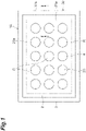
- a sample support 1A illustrated in Figs. 1 and 2 is used for ionization of a sample.
- the sample support 1A includes a substrate 2, a frame 3, and a conductive layer 4.
- the substrate 2 includes a surface 2a and a back surface 2b (a surface on a side opposite to the surface 2a).
- a plurality of through-holes 2c that open to the surface 2a and the back surface 2b are formed in the substrate 2.
- Each of the through-holes 2c extends in a thickness direction D of the substrate 2 (hereinafter, simply referred to as "direction D").
- the direction D is a direction in which the surface 2a and the back surface 2b face each other.
- the substrate 2 is formed of, for example, an insulating material in a rectangular plate shape.
- a length of one side of the substrate 2 when viewed in the direction D is, for example, about several centimeters, and a thickness of the substrate 2 is, for example, 1 to 50 ⁇ m.
- a shape of each through-hole 2c when viewed in the direction D is, for example, substantially circular, and a width of each through-hole 2c is, for example, 1 to 700 nm.
- the plurality of through-holes 2c each having a substantially constant width are uniformly formed (with a uniform distribution) in the substrate 2.
- An aperture ratio of the through-holes 2c in a measurement region R (a proportion occupied by all the through-holes 2c to the measurement region R when viewed in the direction D) is in a range of 10% to 80% in view of practical use, and particularly preferably in a range of 60 to 80%. Further, in the plurality of through-holes 2c, widths of the through-holes 2c may not all be uniform, or the through-holes 2c may be partially connected to each other.
- the width of the through-hole 2c is a value obtained as follows. First, images of the surface 2a and the back surface 2b of the substrate 2 are acquired. Fig. 3 is a view showing an SEM image of the surface 2a of the substrate 2. In the SEM image, black portions are the through-holes 2c, and white portions are partition wall portions between the through-holes 2c.
- a plurality of pixel groups corresponding to a plurality of first openings (openings on the surface 2a side of the through-holes 2c) in the measurement region R are extracted by performing, for example, binarization processing on the acquired image of the surface 2a, and a diameter of a circle having an average area of the first openings is obtained on the basis of a size per pixel.
- a plurality of pixel groups corresponding to a plurality of second openings (openings on the back surface 2b side of the through-holes 2c) in the measurement region R are extracted by performing, for example, binarization processing on the acquired image of the back surface 2b, and a diameter of a circle having an average area of the second openings is obtained on the basis of a size per pixel. Then, an average value of the diameter of the circle acquired for the surface 2a and the diameter of the circle acquired for the back surface 2b is acquired as a width of the through-hole 2c.
- the substrate 2 illustrated in Fig. 3 is an alumina porous film formed by anodizing aluminum (Al).
- the substrate 2 can be obtained by subjecting the Al substrate to an anodizing treatment and peeling an oxidized surface portion from the Al substrate.
- the substrate 2 may be formed by anodizing a valve metal other than Al such as tantalum (Ta), niobium (Nb), titanium (Ti), hafnium (Hf), zirconium (Zr), zinc (Zn), tungsten (W), bismuth (Bi), antimony (Sb), or the like, or may be formed by anodizing silicon (Si).
- the frame 3 is fixed to the surface 2a of the substrate 2 by an adhesive layer (not illustrated).
- an adhesive material for example, a low melting point glass, an adhesive for vacuum, or the like
- the frame 3 is formed in a rectangular plate shape using, for example, a material having the same coefficient of thermal expansion as a material of the substrate 2 or a material having a coefficient of thermal expansion lower than that of the material of the substrate 2 (for example, an iron-nickel alloy (42 alloy), molybdenum, Kovar, titanium, or the like when the material of the substrate 2 is alumina).
- a length of one side of the frame 3 when viewed in the direction D is, for example, about several centimeters, and a thickness of the frame 3 is, for example, 1 mm or less.
- an outer edge of the frame 3 is positioned on an outer side of an outer edge of the substrate 2.
- a plurality of openings disposed two-dimensionally are formed in the frame 3.
- a portion of the substrate 2 corresponding to each of the openings of the frame 3 functions as the measurement region R for ionizing a sample.
- a shape of each opening when viewed in the direction D is, for example, a circle, and a diameter of each opening in that case is, for example, about several millimeters to tens of millimeters.
- the substrate 2 can be prevented from bending after bonding and calcining, and sufficient adhesion between the substrate 2 and a sample S and improvement in sensitivity can be realized in mass spectrometry.
- the substrate 2 and the frame 3 on which the conductive layer 4 is formed are calcined during manufacture of the sample support 1A, crystallinity of the conductive layer 4 can be improved, and a sample support more suitable for mass spectrometry can be obtained.
- the conductive layer 4 is continuously (integrally) formed in a region of the surface 2a of the substrate 2 corresponding to each opening of the frame 3 (that is, a region of the surface 2a of the substrate 2 corresponding to each measurement region R), an inner surface of each opening, and a surface of the frame 3 on a side on which the surface 2a faces in the direction D.
- the conductive layer 4 covers a region of the surface 2a of the substrate 2 in which the plurality of through-holes 2c are not formed in each measurement region R.
- the conductive layer 4 is formed of a conductive material. However, as a material of the conductive layer 4, for the reason to be described below, a metal having a low affinity (reactivity) with a sample and high conductivity is preferably used.
- the conductive layer 4 is formed of, for example, a metal such as copper (Cu) that has a high affinity with a sample such as a protein
- the sample is ionized in a state in which Cu atoms are attached to sample molecules in the process of ionizing the sample, and there is a likelihood that a detection result thereof will deviate in the mass spectrometry method according to an amount of the attached Cu atoms. Therefore, as the material of the conductive layer 4, a metal having a low affinity with a sample is preferably used.
- a metal having higher conductivity tends to apply a constant voltage easily and stably. Therefore, when the conductive layer 4 is formed of a metal having high conductivity, a voltage can be uniformly applied to the surface 2a of the substrate 2 in the measurement region R. Also, a metal having higher conductivity also shows a tendency to have higher thermal conductivity. Therefore, when the conductive layer 4 is formed of a metal having high conductivity, energy of a laser beam irradiated to the substrate 2 can be efficiently transmitted to the sample via the conductive layer 4. Therefore, as the material of the conductive layer 4, a metal having high conductivity is preferably used.
- the material of the conductive layer 4 is preferably used as the material of the conductive layer 4.
- the conductive layer 4 is formed at a thickness of about 1 nm to 350 nm using, for example, a plating method, an atomic layer deposition (ALD) method, a vapor deposition method, a sputtering method, or the like.
- a plating method for example, an atomic layer deposition (ALD) method, a vapor deposition method, a sputtering method, or the like.
- chromium (Cr), nickel (Ni), titanium (Ti), or the like may also be used as the material of the conductive layer 4.
- a film part 20 and a support part 30 are constituted.
- the film part 20 is constituted by the substrate 2, and the conductive layer 4 formed in a region of the surface 2a of the substrate 2 corresponding to each measurement region R.
- the support part 30 is constituted by the frame 3, and the conductive layer 4 formed on a surface of the frame 3 on a side on which the surface 2a faces in the direction D.
- the film part 20 includes a first front surface 20a and a first back surface 20b (a surface on a side opposite to the first front surface 20a).
- the first front surface 20a is a surface of the conductive layer 4 on a side opposite to the substrate 2
- the first back surface 20b is the back surface 2b of the substrate 2.
- a plurality of through-holes 20c that open to the first front surface 20a and the first back surface 20b are formed in the film part 20. Each of the through-holes 20c corresponds to the through-hole 2c formed in the substrate 2.
- a width of each through-hole 20c is, for example, 1 to 700 nm, and the width of the through-hole 20c is a value obtained through the same method as that of the through-hole 2c. Further, illustration of the plurality of through-holes 20c is omitted in Fig. 1 .
- the support part 30 defines a plurality of measurement regions R with respect to the film part 20 and supports the film part 20.
- the support part 30 includes an inner portion 31 and an outer portion 32.
- the inner portion 31 is a portion to which the film part 20 is fixed.
- an outer edge 31c of the inner portion 31 coincides with, for example, an outer edge of the substrate 2.
- the outer portion 32 extends along the outer edge 31c of the inner portion 31.
- an intermediate portion 33 is provided between the inner portion 31 and the outer portion 32, but the intermediate portion 33 may not be provided between the inner portion 31 and the outer portion 32 (that is, the inner portion 31 and the outer portion 32 may be directly connected).
- the inner portion 31 has a second front surface 31a and a second back surface 31b (a surface on a side opposite to the second front surface 31a).
- the second back surface 31b is a surface of the frame 3 on a side opposite to the conductive layer 4 in the direction D
- the second front surface 31a is a surface of the conductive layer 4 on a side opposite to the second back surface 31b in the direction D. That is, the second front surface 31a is a surface of the conductive layer 4 on a side opposite to the frame 3
- the second back surface 31b is a surface of the frame 3 on a side opposite to the conductive layer 4.
- the outer portion 32 has a third front surface 32a and a third back surface 32b (a surface on a side opposite to the third front surface 32a).
- the third back surface 32b is a surface of the frame 3 on a side opposite to the conductive layer 4 in the direction D
- the third front surface 32a is a surface of the conductive layer 4 on a side opposite to the third back surface 32b in the direction D. That is, the third front surface 32a is a surface of the conductive layer 4 on a side opposite to the frame 3
- the third back surface 32b is a surface of the frame 3 on a side opposite to the conductive layer 4.
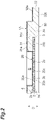
- the first front surface 20a of the film part 20 and the third front surface 32a of the outer portion 32 are positioned on the same plane (the same plane perpendicular to the direction D). That is, a difference generated between a position of the first front surface 20a of the film part 20 and a position of the third front surface 32a of the outer portion 32 in the direction D (a direction that coincides with a thickness direction of the film part 20 (a direction in which the first front surface 20a and the first back surface 20b face each other)) is zero in the present embodiment and is smaller than the thickness of the film part 20.
- the second back surface 31b of the inner portion 31 is positioned on a side (upper side in Fig. 2 ) on which the first front surface 20a of the film part 20 faces in the direction D with respect to the third back surface 32b of the outer portion 32.
- the film part 20 (specifically, the surface 2a of the substrate 2) is fixed to the second back surface 31b of the inner portion 31 by the adhesive layer (not illustrated) described above.
- the substrate 2 is disposed in a recessed part having the second back surface 31b of the inner portion 31 as a bottom surface and surrounded by the intermediate portion 33.
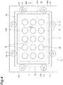
- the adapter 10 illustrated in Figs. 4 and 5 is used for mounting the above-described sample support 1A on a mass spectrometer.
- the adapter 10 includes a holding part 11.
- the holding part 11 includes a main body member 12, a plurality of stoppers 13, and a plurality of sets of washers 14 and bolts 15.
- the main body member 12 is formed in a rectangular frame shape by, for example, a metal material.
- the plurality of stoppers 13 are provided on the main body member 12 to protrude inward of the main body member 12.
- the plurality of sets of washers 14 and bolts 15 can be detachably attached to one surface 12a of the main body member 12.
- the holding part 11 has a reference surface 11a positioned on the same plane as a focal point of a laser beam (the same plane parallel to an optical axis of the laser beam) in the mass spectrometer.
- the reference surface 11a is the surface 12a of the main body member 12.
- the adapter 10 further includes a mount part 16.
- the mount part 16 is formed, for example, in a rectangular plate shape by a metal material.
- the mount part 16 in contact with the first back surface 20b of the film part 20 of the sample support 1A is held by the holding part 11 together with the outer portion 32 of the sample support 1A.
- the mount part 16 includes a contact portion 17 and a held portion 18.
- the held portion 18 extends along an outer edge of the contact portion 17.
- the contact portion 17 is in contact with the first back surface 20b of the film part 20 in the recessed part having the second back surface 31b of the inner portion 31 as a bottom surface and surrounded by the intermediate portion 33.
- the held portion 18 is in contact with the third back surface 32b of the outer portion 32 and is held by the holding part 11 together with the outer portion 32.
- a thickness of the outer portion 32 and the held portion 18 in the direction D is substantially equal to the predetermined distance between a part of each washer 14 and each stopper 13.
- the sample support 1A is disposed on the plurality of stoppers 13 via the mount part 16, the plurality of sets of washers 14 and bolts 15 are fixed to the surface 12a of the main body member 12 in that state, and thereby the sample support 1A is held by the holding part 11 together with the mount part 16.
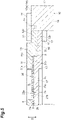
- the reference surface 11a of the holding part 11 and the third front surface 32a of the outer portion 32 are on the same plane (the same plane parallel to the direction D and the optical axis of the laser beam). That is, the holding part 11 holds the outer portion 32 so that the reference surface 11a of the holding part 11 and the third front surface 32a of the outer portion 32 are positioned on the same plane.
- the sample support 1A is prepared (preparation step).
- the sample S is disposed in each measurement region R of the sample support 1A (disposition step).
- a solution containing the sample S is dropped onto each measurement region R.
- a surplus solution permeates through the plurality of through-holes 20c, and components S1 of the sample S is appropriately retained on the conductive layer 4 (that is, on the first front surface 20a of the film part 20).
- the sample support 1A in which the sample S is disposed in each measurement region R is mounted on a mass spectrometer 100 using the adapter 10 (mounting step).
- a laser beam irradiation part 102 of the mass spectrometer 100 is operated to irradiate each measurement region R with a laser beam (an energy beam) L while operating a voltage application part 101 of the mass spectrometer 100 to apply a voltage to the conductive layer 4 of the sample support 1A via the adapter 10.
- the components S1 of the sample S are ionized (ionization step).
- the focal point P of the laser beam L is positioned on the first front surface 20a of the film part 20 in which the components S1 of the sample S are retained.
- the above steps correspond to the ionization method using the sample support 1A and the adapter 10 (in the present embodiment, a laser desorption/ionization method).
- sample ions S2 (ionized components S1) discharged due to ionization of the components S1 of the sample S are detected by an ion detector 103 of the mass spectrometer 100 (detection step). Specifically, the discharged sample ions S2 move while being accelerated toward a ground electrode (not illustrated) provided between the sample support 1A and the ion detector 103 due to an electric potential difference generated between the conductive layer 4 to which a voltage is applied and the ground electrode, and thereby are detected by the ion detector 103.
- the mass spectrometer 100 is a scanning mass spectrometer using time-of-flight mass spectrometry (TOF-MS). The above steps correspond to the mass spectrometry method using the sample support 1A and the adapter 10.
- the first front surface 20a of the film part 20 and the third front surface 32a of the outer portion 32 are positioned on the same plane in the sample support 1A. That is, a difference generated between a position of the first front surface 20a of the film part 20 and a position of the third front surface 32a of the outer portion 32 in the direction D is zero and is smaller than the thickness of the film part 20.
- the sample support 1A when the sample support 1A is mounted on the mass spectrometer 100 using the adapter 10 having the reference surface 11a positioned on the same plane as the focal point P of the laser beam L in the mass spectrometer 100, the focal point P of the laser beam L can be aligned with the first front surface 20a of the film part 20 with higher accuracy by causing the adapter 10 to hold the outer portion 32 so that the reference surface 11a of the adapter 10 and the third front surface 32a of the outer portion 32 are positioned on the same plane. Therefore, the sample support 1A enables highly accurate positioning of the focal point P of the laser beam L in the mass spectrometer 100.
- sample support 1A since it can be attached to the adapter 10 without using a tape or the like, convenience of a user is further enhanced. Moreover, for example, when a similar sample support is fixed on a slide glass with a tape or the like, positioning is required each time, but according to the sample support 1A, such positioning is not necessary.
- the second back surface 31b of the inner portion 31 is positioned on a side on which the first front surface 20a of the film part 20 faces in the direction D with respect to the third back surface 32b of the outer portion 32, and the film part 20 is fixed to the second back surface 31b of the inner portion 31.
- the film part 20 includes the substrate 2 formed of an insulating material and the conductive layer 4 provided on the first front surface 20a side of the substrate 2 in each measurement region R.
- the components S1 of the sample S can be efficiently ionized in the mass spectrometer 100.
- the width of each of the plurality of through-holes 20c is 1 to 700 nm.
- the support part 30 defines the plurality of measurement regions R in the sample support 1A. Thereby, the sample S can be analyzed for each measurement region R in the mass spectrometer 100.
- the holding part 11 has the reference surface 11a positioned on the same plane as the focal point P of the laser beam L in the mass spectrometer 100 and holds the outer portion 32 of the sample support 1A so that the reference surface 11a and the third front surface 32a of the outer portion 32 are positioned on the same plane.
- the focal point P of the laser beam L can be aligned with the first front surface 20a of the film part 20 with high accuracy in the mass spectrometer 100.
- the mount part 16 in contact with the first back surface 20b of the film part 20 is held by the holding part 11 together with the outer portion 32.
- the components S1 of the sample S can be ionized with the focal point P of the laser beam L aligned with the first front surface 20a of the film part 20 with high accuracy.
- a sample support 1B is mainly different in a configuration of a support part 30 from the above-described sample support 1A. That is, in the sample support 1B, a second front surface 31a of an inner portion 31 is positioned on a side on which a first back surface 20b of a film part 20 faces in a direction D (on a lower side in Fig. 7 ) with respect to a third front surface 32a of an outer portion 32.
- the film part 20 (specifically, a back surface 2b of the substrate 2) is fixed to the second front surface 31a of the inner portion 31 by an adhesive layer (not illustrated) described above.
- the substrate 2 is disposed in a recessed part having the second front surface 31a of the inner portion 31 as a bottom surface and surrounded by an intermediate portion 33.
- the sample support 1B can also be mounted on a mass spectrometer 100 using an adapter 10 as in the sample support 1A described above. Then, an ionization method and a mass spectrometry method using the sample support 1B and the adapter 10 can be performed as in the first embodiment.
- a first front surface 20a of the film part 20 and the third front surface 32a of the outer portion 32 are positioned on the same plane. That is, a difference generated between a position of the first front surface 20a of the film part 20 and a position of the third front surface 32a of the outer portion 32 in the direction D is zero and is smaller than a thickness of the film part 20.
- the sample support 1B when the sample support 1B is mounted on the mass spectrometer 100 using the adapter 10 having a reference surface 11a positioned on the same plane as a focal point P of a laser beam L in the mass spectrometer 100, the focal point P of the laser beam L can be aligned with the first front surface 20a of the film part 20 with higher accuracy by causing the adapter 10 to hold the outer portion 32 so that the reference surface 11a of the adapter 10 and the third front surface 32a of the outer portion 32 are positioned on the same plane. Therefore, the sample support 1B enables highly accurate positioning of the focal point P of the laser beam L in the mass spectrometer 100.
- sample support 1B since it can be attached to the adapter 10 without using a tape or the like, convenience of a user is further enhanced. Moreover, for example, when a similar sample support is fixed on a slide glass with a tape or the like, positioning is required each time, but according to the sample support 1B, such positioning is not necessary.
- the second front surface 31a of the inner portion 31 is positioned on a side on which the first back surface 20b of the film part 20 faces in the direction D with respect to the third front surface 32a of the outer portion 32, and the film part 20 is fixed to the second front surface 31a of the inner portion 31.
- the film part 20 includes the substrate 2 formed of an insulating material and a conductive layer 4 provided on the first front surface 20a side of the substrate 2 in each measurement region R.
- components S1 of a sample S can be efficiently ionized in the mass spectrometer 100.
- a width of each of a plurality of through-holes 20c is 1 to 700 nm in the sample support 1B.
- the support part 30 defines the plurality of measurement regions R in the sample support 1B. Thereby, the sample S can be analyzed for each measurement region R in the mass spectrometer 100.
- a holding part 11 has the reference surface 11a positioned on the same plane as the focal point P of the laser beam L in the mass spectrometer 100 and holds the outer portion 32 of the sample support 1B so that the reference surface 11a and the third front surface 32a of the outer portion 32 are positioned on the same plane.
- the focal point P of the laser beam L can be aligned with the first front surface 20a of the film part 20 with high accuracy in the mass spectrometer 100.
- a mount part 16 in contact with the first back surface 20b of the film part 20 is held by the holding part 11 together with the outer portion 32.
- the components S1 of the sample S can be ionized with the focal point P of the laser beam L aligned with the first front surface 20a of the film part 20 with high accuracy.
- a thickness of the outer portion 32 in the direction D may be substantially equal to a predetermined distance between a part of each washer 14 and each stopper 13. In these cases, each of the sample support 1A and the sample support 1B can be attached to the adapter 10 without using the mount part 16.
- each of the sample support 1A and the sample support 1B if a difference generated between a position of the first front surface 20a of the film part 20 and a position of the third front surface 32a of the outer portion 32 in the direction D is smaller than a thickness of the film part 20, the first front surface 20a of the film part 20 and the third front surface 32a of the outer portion 32 may not be positioned on the same plane perpendicular to the direction D.
- the focal point P of the laser beam L can be aligned with the first front surface 20a of the film part 20 at a lower level than the thickness of the film part 20.
- the holding part 11 of the adapter 10 is not limited to the above-described configuration (that is, the configuration including the main body member 12, the plurality of stoppers 13, and the plurality of sets of washers 14 and bolts 15) as long as it can hold the outer portion 32 so that the reference surface 11a of the adapter 10 and the third front surface 32a of the outer portion 32 are positioned on the same plane.
- the conductive layer 4 may be provided at least on the surface 2a of the substrate 2. That is, when the conductive layer 4 is provided on the surface 2a of the substrate 2, the conductive layer 4 may or may not be provided on the back surface 2b of the substrate 2 and on the inner surface of each through-hole 2c.
- the substrate 2 may have conductivity in each of the sample support 1A and the sample support 1B. According to such a configuration, since a voltage can be applied to the substrate 2 when the ionization method and the mass spectrometry method are performed, the conductive layer 4 can be omitted in each of the sample support 1A and the sample support 1B.
- the support part 30 may define one measurement region R in each of the sample support 1A and the sample support 1B.
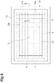
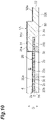
- the sample support 1A may further include a reinforcing layer 5 in which a plurality of openings 5c are formed to have an aperture ratio larger than the aperture ratio of the through-holes 2c in the measurement region R.
- the reinforcing layer 5 may be formed, for example, in a mesh shape and is provided on the back surface 2b side of the substrate 2.
- the sample support 1B may further include a reinforcing layer in which a plurality of openings are formed to have an aperture ratio larger than the aperture ratio of the through-holes 2c in the measurement region R.
- applications of the sample support 1A and the sample support 1B are not limited to the ionization of the sample S using irradiation of the laser beam L.
- the sample support 1A and the sample support 1B can be used for ionization of the sample S using irradiation of an energy beam such as a laser beam, an ion beam, or an electron beam.
- the sample S can be ionized by irradiation of an energy beam.
- 1A, 1B Sample support, 2: Substrate, 4: Conductive layer, 10: Adapter, 11: Holding part, 11a: Reference surface, 16: Mount part, 20: Film part, 20a: First front surface, 20b: First back surface, 20c: Through-hole, 30: Support part, 31: Inner portion, 31a: Second front surface, 31b: Second back surface, 31c: Outer edge, 32: Outer portion, 32a: Third front surface, 32b: Third back surface, 100: Mass spectrometer, D: Direction (thickness direction), L: Laser beam (energy beam), P: Focal point, R: Measurement region, S: Sample, S1: Component, S2: Sample ion (ionized component).
Landscapes
- Chemical & Material Sciences (AREA)
- Analytical Chemistry (AREA)
- Physics & Mathematics (AREA)
- Optics & Photonics (AREA)
- Biochemistry (AREA)
- Immunology (AREA)
- Health & Medical Sciences (AREA)
- Life Sciences & Earth Sciences (AREA)
- Chemical Kinetics & Catalysis (AREA)
- General Health & Medical Sciences (AREA)
- General Physics & Mathematics (AREA)
- Electrochemistry (AREA)
- Pathology (AREA)
- Engineering & Computer Science (AREA)
- Plasma & Fusion (AREA)
- Other Investigation Or Analysis Of Materials By Electrical Means (AREA)
- Electron Tubes For Measurement (AREA)
- Sampling And Sample Adjustment (AREA)
Abstract
Description
- The present disclosure relates to a sample support, an adapter, an ionization method, and a mass spectrometry method.
- Conventionally, a laser desorption/ionization method is known as a method of ionizing a sample such as a biological sample to perform mass spectrometry or the like. As a sample support used in a laser desorption/ionization method,
Patent Literature 1 describes one including a substrate in which a plurality of through-holes are formed and a conductive layer provided on at least one surface of the substrate. - [Patent Literature 1]
Japanese Patent No. 6093492 - When a sample support as described above is mounted on a mass spectrometer, an adapter having a reference surface positioned on the same plane as a focal point of an energy beam such as a laser beam may be used in the mass spectrometer. In such a case, when a focal point of an energy beam is aligned with a conductive layer provided on one surface of the substrate with high accuracy, sensitivity and resolution are improved in detection of components of the ionized sample.
- Therefore, an objective of the present disclosure is to provide a sample support, an adapter, an ionization method, and a mass spectrometry method that enable highly accurate positioning of a focal point of an energy beam in a mass spectrometer.
- A sample support of one aspect of the present disclosure is a sample support used for ionization of a sample and includes a film part having a first front surface and a first back surface, the film part being formed with a plurality of through-holes opening to the first front surface and the first back surface, and a support part defining a measurement region for ionizing the sample with respect to the film part and supporting the film part, in which the support part includes an inner portion having a second front surface and a second back surface, the film part being fixed to the inner portion, and an outer portion having a third front surface and a third back surface and extending along an outer edge of the inner portion, and a difference generated between a position of the first front surface and a position of the third front surface in a thickness direction of the film part is smaller than a thickness of the film part.
- In the sample support, a difference generated between a position of the first front surface of the film part and a position of the third front surface of the outer portion in the thickness direction of the film part is smaller than the thickness of the film part. Thereby, when the sample support is mounted on a mass spectrometer using an adapter having a reference surface positioned on the same plane as a focal point of an energy beam such as a laser beam in the mass spectrometer, the focal point of the energy beam can be aligned with the first front surface of the film part at a lower level than the thickness of the film part by causing the adapter to hold the outer portion so that the reference surface of the adapter and the third front surface of the outer portion are positioned on the same plane. Therefore, the sample support enables highly accurate positioning of a focal point of the energy beam in the mass spectrometer.
- In the sample support of one aspect of the present disclosure, the first front surface and the third front surface may be positioned on the same plane. Thereby, a focal point of the energy beam can be more accurately aligned with the first front surface of the film part in the mass spectrometer.
- In the sample support of one aspect of the present disclosure, the second back surface may be positioned on a side on which the first front surface faces in the thickness direction with respect to the third back surface, and the film part may be fixed to the second back surface. Thereby, a configuration in which a focal point of the energy beam can be aligned with the first front surface of the film part with high accuracy can be realized with a simple structure.
- In the sample support of one aspect of the present disclosure, the second front surface may be positioned on a side on which the first back surface faces in the thickness direction with respect to the third front surface, and the film part may be fixed to the second front surface. Thereby, a configuration in which a focal point of the energy beam can be aligned with the first front surface of the film part with high accuracy can be realized with a simple structure.
- In the sample support of one aspect of the present disclosure, the film part may include a substrate formed of an insulating material, and a conductive layer provided at least on the first front surface side with respect to the substrate at least in the measurement region. Thereby, components of the sample can be efficiently ionized in the mass spectrometer.
- In the sample support of one aspect of the present disclosure, a width of each of the plurality of through-holes may be 1 to 700 nm. Thereby, components of the sample can be appropriately retained on the first front surface of the film part.
- In the sample support of one aspect of the present disclosure, the support part may define a plurality of measurement regions, each of the plurality of measurement regions being the measurement region. Thereby, the sample can be analyzed for each measurement region in the mass spectrometer.
- An adapter of one aspect of the present disclosure is an adapter used for mounting the above-described sample support on a mass spectrometer and includes a holding part having a reference surface positioned on the same plane as a focal point of an energy beam in the mass spectrometer and configured to hold the outer portion so that the reference surface and the third front surface are positioned on the same plane.
- According to the adapter, a focal point of the energy beam can be aligned with the first front surface of the film part with high accuracy in the mass spectrometer.
- The adapter of one aspect of the present disclosure may further include a mount part configured to be held by the holding part together with the outer portion in a state in which the mount part is in contact with the first back surface. Thereby, since the film part can be stably supported, a focal point of the energy beam can be more accurately aligned with the first front surface of the film part in the mass spectrometer.
- An ionization method of one aspect of the present disclosure includes a step of preparing the above-described sample support, a step of disposing the sample in the measurement region, a step of mounting the sample support on a mass spectrometer using an adapter including a holding part having a reference surface positioned on the same plane as a focal point of an energy beam in the mass spectrometer and configured to hold the outer portion so that the reference surface and the third front surface are positioned on the same plane, and a step of ionizing components of the sample by irradiating the measurement region with an energy beam.
- According to the ionization method, components of the sample can be ionized with a focal point of the energy beam aligned with the first front surface of the film part with high accuracy.
- A mass spectrometry method of one aspect of the present disclosure includes a plurality of steps included in the above-described ionization method, and a step of detecting the ionized components.
- In the mass spectrometry method, since components of the sample are ionized with the focal point of the energy beam aligned with the first front surface of the film part with high accuracy, sensitivity and resolution can be improved in detection of the ionized components.
- According to the present disclosure, it is possible to provide a sample support, an adapter, an ionization method, and a mass spectrometry method that enable highly accurate positioning of a focal point of an energy beam in a mass spectrometer.
-
-
Fig. 1 is a plan view of a sample support of a first embodiment. -
Fig. 2 is a cross-sectional view along line II-II illustrated inFig. 1 . -
Fig. 3 is a view showing an SEM image of a surface of a substrate illustrated inFig. 1 . -
Fig. 4 is a plan view of the sample support and an adapter of the first embodiment. -
Fig. 5 is a cross-sectional view along line V-V illustrated inFig. 4 . -
Fig. 6 is a view illustrating a mass spectrometry method of the first embodiment. -
Fig. 7 is a cross-sectional view of a part of a sample support of a second embodiment. -
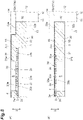
Fig. 8 is a cross-sectional view of a part of a sample support of a modified example. -
Fig. 9 is a plan view of the sample support of the modified example. -
Fig. 10 is a cross-sectional view along line X-X illustrated inFig. 9 . - Hereinafter, embodiments of the present disclosure will be described in detail with reference to the drawings. In each of the drawings, the same or corresponding portions are denoted by the same reference signs, and duplicate descriptions thereof will be omitted.
- A
sample support 1A illustrated inFigs. 1 and2 is used for ionization of a sample. Thesample support 1A includes asubstrate 2, aframe 3, and aconductive layer 4. Thesubstrate 2 includes asurface 2a and aback surface 2b (a surface on a side opposite to thesurface 2a). A plurality of through-holes 2c that open to thesurface 2a and theback surface 2b are formed in thesubstrate 2. Each of the through-holes 2c extends in a thickness direction D of the substrate 2 (hereinafter, simply referred to as "direction D"). The direction D is a direction in which thesurface 2a and theback surface 2b face each other. - The
substrate 2 is formed of, for example, an insulating material in a rectangular plate shape. A length of one side of thesubstrate 2 when viewed in the direction D is, for example, about several centimeters, and a thickness of thesubstrate 2 is, for example, 1 to 50 µm. A shape of each through-hole 2c when viewed in the direction D is, for example, substantially circular, and a width of each through-hole 2c is, for example, 1 to 700 nm. The plurality of through-holes 2c each having a substantially constant width are uniformly formed (with a uniform distribution) in thesubstrate 2. An aperture ratio of the through-holes 2c in a measurement region R (a proportion occupied by all the through-holes 2c to the measurement region R when viewed in the direction D) is in a range of 10% to 80% in view of practical use, and particularly preferably in a range of 60 to 80%. Further, in the plurality of through-holes 2c, widths of the through-holes 2c may not all be uniform, or the through-holes 2c may be partially connected to each other. - The width of the through-
hole 2c is a value obtained as follows. First, images of thesurface 2a and theback surface 2b of thesubstrate 2 are acquired.Fig. 3 is a view showing an SEM image of thesurface 2a of thesubstrate 2. In the SEM image, black portions are the through-holes 2c, and white portions are partition wall portions between the through-holes 2c. Next, a plurality of pixel groups corresponding to a plurality of first openings (openings on thesurface 2a side of the through-holes 2c) in the measurement region R (to be described later) are extracted by performing, for example, binarization processing on the acquired image of thesurface 2a, and a diameter of a circle having an average area of the first openings is obtained on the basis of a size per pixel. Similarly, a plurality of pixel groups corresponding to a plurality of second openings (openings on theback surface 2b side of the through-holes 2c) in the measurement region R are extracted by performing, for example, binarization processing on the acquired image of theback surface 2b, and a diameter of a circle having an average area of the second openings is obtained on the basis of a size per pixel. Then, an average value of the diameter of the circle acquired for thesurface 2a and the diameter of the circle acquired for theback surface 2b is acquired as a width of the through-hole 2c. - The
substrate 2 illustrated inFig. 3 is an alumina porous film formed by anodizing aluminum (Al). Specifically, thesubstrate 2 can be obtained by subjecting the Al substrate to an anodizing treatment and peeling an oxidized surface portion from the Al substrate. Further, thesubstrate 2 may be formed by anodizing a valve metal other than Al such as tantalum (Ta), niobium (Nb), titanium (Ti), hafnium (Hf), zirconium (Zr), zinc (Zn), tungsten (W), bismuth (Bi), antimony (Sb), or the like, or may be formed by anodizing silicon (Si). - As illustrated in
Figs. 1 and2 , theframe 3 is fixed to thesurface 2a of thesubstrate 2 by an adhesive layer (not illustrated). As a material of the adhesive layer, an adhesive material (for example, a low melting point glass, an adhesive for vacuum, or the like) having little discharge gas is preferably used. Theframe 3 is formed in a rectangular plate shape using, for example, a material having the same coefficient of thermal expansion as a material of thesubstrate 2 or a material having a coefficient of thermal expansion lower than that of the material of the substrate 2 (for example, an iron-nickel alloy (42 alloy), molybdenum, Kovar, titanium, or the like when the material of thesubstrate 2 is alumina). A length of one side of theframe 3 when viewed in the direction D is, for example, about several centimeters, and a thickness of theframe 3 is, for example, 1 mm or less. When viewed from the direction D, an outer edge of theframe 3 is positioned on an outer side of an outer edge of thesubstrate 2. A plurality of openings disposed two-dimensionally (for example, in a matrix form such as 3 rows and 5 columns) are formed in theframe 3. A portion of thesubstrate 2 corresponding to each of the openings of theframe 3 functions as the measurement region R for ionizing a sample. A shape of each opening when viewed in the direction D is, for example, a circle, and a diameter of each opening in that case is, for example, about several millimeters to tens of millimeters. Further, when a material having the same coefficient of thermal expansion as the material of thesubstrate 2 or a material having a coefficient of thermal expansion lower than that of the material of thesubstrate 2 is used for theframe 3, thesubstrate 2 can be prevented from bending after bonding and calcining, and sufficient adhesion between thesubstrate 2 and a sample S and improvement in sensitivity can be realized in mass spectrometry. When thesubstrate 2 and theframe 3 on which theconductive layer 4 is formed are calcined during manufacture of thesample support 1A, crystallinity of theconductive layer 4 can be improved, and a sample support more suitable for mass spectrometry can be obtained. - The
conductive layer 4 is continuously (integrally) formed in a region of thesurface 2a of thesubstrate 2 corresponding to each opening of the frame 3 (that is, a region of thesurface 2a of thesubstrate 2 corresponding to each measurement region R), an inner surface of each opening, and a surface of theframe 3 on a side on which thesurface 2a faces in the direction D. Theconductive layer 4 covers a region of thesurface 2a of thesubstrate 2 in which the plurality of through-holes 2c are not formed in each measurement region R. Theconductive layer 4 is formed of a conductive material. However, as a material of theconductive layer 4, for the reason to be described below, a metal having a low affinity (reactivity) with a sample and high conductivity is preferably used. - When the
conductive layer 4 is formed of, for example, a metal such as copper (Cu) that has a high affinity with a sample such as a protein, the sample is ionized in a state in which Cu atoms are attached to sample molecules in the process of ionizing the sample, and there is a likelihood that a detection result thereof will deviate in the mass spectrometry method according to an amount of the attached Cu atoms. Therefore, as the material of theconductive layer 4, a metal having a low affinity with a sample is preferably used. - On the other hand, a metal having higher conductivity tends to apply a constant voltage easily and stably. Therefore, when the
conductive layer 4 is formed of a metal having high conductivity, a voltage can be uniformly applied to thesurface 2a of thesubstrate 2 in the measurement region R. Also, a metal having higher conductivity also shows a tendency to have higher thermal conductivity. Therefore, when theconductive layer 4 is formed of a metal having high conductivity, energy of a laser beam irradiated to thesubstrate 2 can be efficiently transmitted to the sample via theconductive layer 4. Therefore, as the material of theconductive layer 4, a metal having high conductivity is preferably used. - From the above viewpoint, for example, gold (Au), platinum (Pt), or the like is preferably used as the material of the
conductive layer 4. Theconductive layer 4 is formed at a thickness of about 1 nm to 350 nm using, for example, a plating method, an atomic layer deposition (ALD) method, a vapor deposition method, a sputtering method, or the like. Further, as the material of theconductive layer 4, for example, chromium (Cr), nickel (Ni), titanium (Ti), or the like may also be used. - In the
above sample support 1A, afilm part 20 and asupport part 30 are constituted. Thefilm part 20 is constituted by thesubstrate 2, and theconductive layer 4 formed in a region of thesurface 2a of thesubstrate 2 corresponding to each measurement region R. Thesupport part 30 is constituted by theframe 3, and theconductive layer 4 formed on a surface of theframe 3 on a side on which thesurface 2a faces in the direction D. - The
film part 20 includes a firstfront surface 20a and afirst back surface 20b (a surface on a side opposite to the firstfront surface 20a). In the present embodiment, the firstfront surface 20a is a surface of theconductive layer 4 on a side opposite to thesubstrate 2, and thefirst back surface 20b is theback surface 2b of thesubstrate 2. A plurality of through-holes 20c that open to the firstfront surface 20a and thefirst back surface 20b are formed in thefilm part 20. Each of the through-holes 20c corresponds to the through-hole 2c formed in thesubstrate 2. Therefore, a width of each through-hole 20c is, for example, 1 to 700 nm, and the width of the through-hole 20c is a value obtained through the same method as that of the through-hole 2c. Further, illustration of the plurality of through-holes 20c is omitted inFig. 1 . - The
support part 30 defines a plurality of measurement regions R with respect to thefilm part 20 and supports thefilm part 20. Thesupport part 30 includes aninner portion 31 and anouter portion 32. Theinner portion 31 is a portion to which thefilm part 20 is fixed. When viewed in the direction D, anouter edge 31c of theinner portion 31 coincides with, for example, an outer edge of thesubstrate 2. Theouter portion 32 extends along theouter edge 31c of theinner portion 31. In the present embodiment, anintermediate portion 33 is provided between theinner portion 31 and theouter portion 32, but theintermediate portion 33 may not be provided between theinner portion 31 and the outer portion 32 (that is, theinner portion 31 and theouter portion 32 may be directly connected). - The
inner portion 31 has a secondfront surface 31a and asecond back surface 31b (a surface on a side opposite to the secondfront surface 31a). In the present embodiment, thesecond back surface 31b is a surface of theframe 3 on a side opposite to theconductive layer 4 in the direction D, and the secondfront surface 31a is a surface of theconductive layer 4 on a side opposite to thesecond back surface 31b in the direction D. That is, the secondfront surface 31a is a surface of theconductive layer 4 on a side opposite to theframe 3, and thesecond back surface 31b is a surface of theframe 3 on a side opposite to theconductive layer 4. Theouter portion 32 has a thirdfront surface 32a and athird back surface 32b (a surface on a side opposite to the thirdfront surface 32a). In the present embodiment, thethird back surface 32b is a surface of theframe 3 on a side opposite to theconductive layer 4 in the direction D, and the thirdfront surface 32a is a surface of theconductive layer 4 on a side opposite to thethird back surface 32b in the direction D. That is, the thirdfront surface 32a is a surface of theconductive layer 4 on a side opposite to theframe 3, and thethird back surface 32b is a surface of theframe 3 on a side opposite to theconductive layer 4. - The first
front surface 20a of thefilm part 20 and the thirdfront surface 32a of theouter portion 32 are positioned on the same plane (the same plane perpendicular to the direction D). That is, a difference generated between a position of the firstfront surface 20a of thefilm part 20 and a position of the thirdfront surface 32a of theouter portion 32 in the direction D (a direction that coincides with a thickness direction of the film part 20 (a direction in which the firstfront surface 20a and thefirst back surface 20b face each other)) is zero in the present embodiment and is smaller than the thickness of thefilm part 20. - The
second back surface 31b of theinner portion 31 is positioned on a side (upper side inFig. 2 ) on which the firstfront surface 20a of thefilm part 20 faces in the direction D with respect to thethird back surface 32b of theouter portion 32. The film part 20 (specifically, thesurface 2a of the substrate 2) is fixed to thesecond back surface 31b of theinner portion 31 by the adhesive layer (not illustrated) described above. In the present embodiment, thesubstrate 2 is disposed in a recessed part having thesecond back surface 31b of theinner portion 31 as a bottom surface and surrounded by theintermediate portion 33. - An
adapter 10 illustrated inFigs. 4 and5 is used for mounting the above-describedsample support 1A on a mass spectrometer. Theadapter 10 includes a holdingpart 11. The holdingpart 11 includes amain body member 12, a plurality ofstoppers 13, and a plurality of sets ofwashers 14 andbolts 15. Themain body member 12 is formed in a rectangular frame shape by, for example, a metal material. The plurality ofstoppers 13 are provided on themain body member 12 to protrude inward of themain body member 12. The plurality of sets ofwashers 14 andbolts 15 can be detachably attached to onesurface 12a of themain body member 12. In a state in which the plurality of sets ofwashers 14 andbolts 15 are fixed to thesurface 12a of themain body member 12, a part of eachwasher 14 and eachstopper 13 face each other via a predetermined distance in the direction D. The holdingpart 11 has areference surface 11a positioned on the same plane as a focal point of a laser beam (the same plane parallel to an optical axis of the laser beam) in the mass spectrometer. In the present embodiment, thereference surface 11a is thesurface 12a of themain body member 12. - The
adapter 10 further includes amount part 16. Themount part 16 is formed, for example, in a rectangular plate shape by a metal material. Themount part 16 in contact with thefirst back surface 20b of thefilm part 20 of thesample support 1A is held by the holdingpart 11 together with theouter portion 32 of thesample support 1A. Specifically, themount part 16 includes acontact portion 17 and a heldportion 18. The heldportion 18 extends along an outer edge of thecontact portion 17. Thecontact portion 17 is in contact with thefirst back surface 20b of thefilm part 20 in the recessed part having thesecond back surface 31b of theinner portion 31 as a bottom surface and surrounded by theintermediate portion 33. The heldportion 18 is in contact with thethird back surface 32b of theouter portion 32 and is held by the holdingpart 11 together with theouter portion 32. In the present embodiment, a thickness of theouter portion 32 and the heldportion 18 in the direction D is substantially equal to the predetermined distance between a part of eachwasher 14 and eachstopper 13. - The
sample support 1A is disposed on the plurality ofstoppers 13 via themount part 16, the plurality of sets ofwashers 14 andbolts 15 are fixed to thesurface 12a of themain body member 12 in that state, and thereby thesample support 1A is held by the holdingpart 11 together with themount part 16. In a state in which thesample support 1A is held by the holdingpart 11, thereference surface 11a of the holdingpart 11 and the thirdfront surface 32a of theouter portion 32 are on the same plane (the same plane parallel to the direction D and the optical axis of the laser beam). That is, the holdingpart 11 holds theouter portion 32 so that thereference surface 11a of the holdingpart 11 and the thirdfront surface 32a of theouter portion 32 are positioned on the same plane. - An ionization method and a mass spectrometry method using the
sample support 1A and theadapter 10 described above will be described with reference toFig. 6 . First, thesample support 1A is prepared (preparation step). Next, the sample S is disposed in each measurement region R of thesample support 1A (disposition step). In the present embodiment, for example, a solution containing the sample S is dropped onto each measurement region R. Thereby, in each measurement region R, a surplus solution permeates through the plurality of through-holes 20c, and components S1 of the sample S is appropriately retained on the conductive layer 4 (that is, on the firstfront surface 20a of the film part 20). Next, thesample support 1A in which the sample S is disposed in each measurement region R is mounted on amass spectrometer 100 using the adapter 10 (mounting step). - Next, a laser
beam irradiation part 102 of themass spectrometer 100 is operated to irradiate each measurement region R with a laser beam (an energy beam) L while operating avoltage application part 101 of themass spectrometer 100 to apply a voltage to theconductive layer 4 of thesample support 1A via theadapter 10. Thereby, the components S1 of the sample S are ionized (ionization step). At this time, since a focal point P of the laser beam L and thereference surface 11a of the holdingpart 11 are positioned on the same plane, thereference surface 11a of the holdingpart 11 and the thirdfront surface 32a of theouter portion 32 are positioned on the same plane, and the thirdfront surface 32a of theouter portion 32 and the firstfront surface 20a of thefilm part 20 are positioned on the same plane, the focal point P of the laser beam L is positioned on the firstfront surface 20a of thefilm part 20 in which the components S1 of the sample S are retained. The above steps correspond to the ionization method using thesample support 1A and the adapter 10 (in the present embodiment, a laser desorption/ionization method). - Next, sample ions S2 (ionized components S1) discharged due to ionization of the components S1 of the sample S are detected by an
ion detector 103 of the mass spectrometer 100 (detection step). Specifically, the discharged sample ions S2 move while being accelerated toward a ground electrode (not illustrated) provided between thesample support 1A and theion detector 103 due to an electric potential difference generated between theconductive layer 4 to which a voltage is applied and the ground electrode, and thereby are detected by theion detector 103. In the present embodiment, themass spectrometer 100 is a scanning mass spectrometer using time-of-flight mass spectrometry (TOF-MS). The above steps correspond to the mass spectrometry method using thesample support 1A and theadapter 10. - As described above, the first
front surface 20a of thefilm part 20 and the thirdfront surface 32a of theouter portion 32 are positioned on the same plane in thesample support 1A. That is, a difference generated between a position of the firstfront surface 20a of thefilm part 20 and a position of the thirdfront surface 32a of theouter portion 32 in the direction D is zero and is smaller than the thickness of thefilm part 20. Thereby, when thesample support 1A is mounted on themass spectrometer 100 using theadapter 10 having thereference surface 11a positioned on the same plane as the focal point P of the laser beam L in themass spectrometer 100, the focal point P of the laser beam L can be aligned with the firstfront surface 20a of thefilm part 20 with higher accuracy by causing theadapter 10 to hold theouter portion 32 so that thereference surface 11a of theadapter 10 and the thirdfront surface 32a of theouter portion 32 are positioned on the same plane. Therefore, thesample support 1A enables highly accurate positioning of the focal point P of the laser beam L in themass spectrometer 100. - Also, according to the
sample support 1A, since it can be attached to theadapter 10 without using a tape or the like, convenience of a user is further enhanced. Moreover, for example, when a similar sample support is fixed on a slide glass with a tape or the like, positioning is required each time, but according to thesample support 1A, such positioning is not necessary. - Also, in the
sample support 1A, thesecond back surface 31b of theinner portion 31 is positioned on a side on which the firstfront surface 20a of thefilm part 20 faces in the direction D with respect to thethird back surface 32b of theouter portion 32, and thefilm part 20 is fixed to thesecond back surface 31b of theinner portion 31. Thereby, a configuration in which the focal point P of the laser beam L can be aligned with the firstfront surface 20a of thefilm part 20 with high accuracy can be realized with a simple structure. - Also, in the
sample support 1A, thefilm part 20 includes thesubstrate 2 formed of an insulating material and theconductive layer 4 provided on the firstfront surface 20a side of thesubstrate 2 in each measurement region R. Thereby, the components S1 of the sample S can be efficiently ionized in themass spectrometer 100. - Also, in the
sample support 1A, the width of each of the plurality of through-holes 20c is 1 to 700 nm. Thereby, the components S1 of the sample S can be appropriately retained on the firstfront surface 20a of thefilm part 20. - Also, the
support part 30 defines the plurality of measurement regions R in thesample support 1A. Thereby, the sample S can be analyzed for each measurement region R in themass spectrometer 100. - Also, in the
adapter 10, the holdingpart 11 has thereference surface 11a positioned on the same plane as the focal point P of the laser beam L in themass spectrometer 100 and holds theouter portion 32 of thesample support 1A so that thereference surface 11a and the thirdfront surface 32a of theouter portion 32 are positioned on the same plane. Thereby, the focal point P of the laser beam L can be aligned with the firstfront surface 20a of thefilm part 20 with high accuracy in themass spectrometer 100. - Also, in the
adapter 10, themount part 16 in contact with thefirst back surface 20b of thefilm part 20 is held by the holdingpart 11 together with theouter portion 32. Thereby, since thefilm part 20 can be stably supported, the focal point P of the laser beam L can be more accurately aligned with the firstfront surface 20a of thefilm part 20 in themass spectrometer 100. - Also, according to the ionization method using the
sample support 1A and theadapter 10, the components S1 of the sample S can be ionized with the focal point P of the laser beam L aligned with the firstfront surface 20a of thefilm part 20 with high accuracy. - Also, in the mass spectrometry method using the
sample support 1A and theadapter 10, since the components S1 of the sample S are ionized with the focal point P of the laser beam L aligned with the firstfront surface 20a of thefilm part 20 with high accuracy, sensitivity and resolution can be improved in detection of the sample ions S2. - As illustrated in
Fig. 7 , asample support 1B is mainly different in a configuration of asupport part 30 from the above-describedsample support 1A. That is, in thesample support 1B, a secondfront surface 31a of aninner portion 31 is positioned on a side on which afirst back surface 20b of afilm part 20 faces in a direction D (on a lower side inFig. 7 ) with respect to a thirdfront surface 32a of anouter portion 32. The film part 20 (specifically, aback surface 2b of the substrate 2) is fixed to the secondfront surface 31a of theinner portion 31 by an adhesive layer (not illustrated) described above. In the present embodiment, thesubstrate 2 is disposed in a recessed part having the secondfront surface 31a of theinner portion 31 as a bottom surface and surrounded by anintermediate portion 33. Further, thesample support 1B can also be mounted on amass spectrometer 100 using anadapter 10 as in thesample support 1A described above. Then, an ionization method and a mass spectrometry method using thesample support 1B and theadapter 10 can be performed as in the first embodiment. - In the
sample support 1B configured as described above, a firstfront surface 20a of thefilm part 20 and the thirdfront surface 32a of theouter portion 32 are positioned on the same plane. That is, a difference generated between a position of the firstfront surface 20a of thefilm part 20 and a position of the thirdfront surface 32a of theouter portion 32 in the direction D is zero and is smaller than a thickness of thefilm part 20. Thereby, when thesample support 1B is mounted on themass spectrometer 100 using theadapter 10 having areference surface 11a positioned on the same plane as a focal point P of a laser beam L in themass spectrometer 100, the focal point P of the laser beam L can be aligned with the firstfront surface 20a of thefilm part 20 with higher accuracy by causing theadapter 10 to hold theouter portion 32 so that thereference surface 11a of theadapter 10 and the thirdfront surface 32a of theouter portion 32 are positioned on the same plane. Therefore, thesample support 1B enables highly accurate positioning of the focal point P of the laser beam L in themass spectrometer 100. - Also, according to the
sample support 1B, since it can be attached to theadapter 10 without using a tape or the like, convenience of a user is further enhanced. Moreover, for example, when a similar sample support is fixed on a slide glass with a tape or the like, positioning is required each time, but according to thesample support 1B, such positioning is not necessary. - Also, in the
sample support 1B, the secondfront surface 31a of theinner portion 31 is positioned on a side on which thefirst back surface 20b of thefilm part 20 faces in the direction D with respect to the thirdfront surface 32a of theouter portion 32, and thefilm part 20 is fixed to the secondfront surface 31a of theinner portion 31. Thereby, a configuration in which the focal point P of the laser beam L can be aligned with the firstfront surface 20a of thefilm part 20 with high accuracy can be realized with a simple structure. - Also, in the
sample support 1B, thefilm part 20 includes thesubstrate 2 formed of an insulating material and aconductive layer 4 provided on the firstfront surface 20a side of thesubstrate 2 in each measurement region R. Thereby, components S1 of a sample S can be efficiently ionized in themass spectrometer 100. - Also, a width of each of a plurality of through-
holes 20c is 1 to 700 nm in thesample support 1B. Thereby, the components S1 of the sample S can be appropriately retained on the firstfront surface 20a of thefilm part 20. - Also, the
support part 30 defines the plurality of measurement regions R in thesample support 1B. Thereby, the sample S can be analyzed for each measurement region R in themass spectrometer 100. - Also, in the
adapter 10, a holdingpart 11 has thereference surface 11a positioned on the same plane as the focal point P of the laser beam L in themass spectrometer 100 and holds theouter portion 32 of thesample support 1B so that thereference surface 11a and the thirdfront surface 32a of theouter portion 32 are positioned on the same plane. Thereby, the focal point P of the laser beam L can be aligned with the firstfront surface 20a of thefilm part 20 with high accuracy in themass spectrometer 100. - Also, in the
adapter 10, amount part 16 in contact with thefirst back surface 20b of thefilm part 20 is held by the holdingpart 11 together with theouter portion 32. Thereby, since thefilm part 20 can be stably supported, the focal point P of the laser beam L can be more accurately aligned with the firstfront surface 20a of thefilm part 20 in themass spectrometer 100. - Also, according to the ionization method using the
sample support 1B and theadapter 10, the components S1 of the sample S can be ionized with the focal point P of the laser beam L aligned with the firstfront surface 20a of thefilm part 20 with high accuracy. - Also, in the mass spectrometry method using the
sample support 1B and theadapter 10, since the components S1 of the sample S are ionized with the focal point P of the laser beam L aligned with the firstfront surface 20a of thefilm part 20 with high accuracy, sensitivity and resolution can be improved in detection of sample ions S2. - As illustrated in (a) and (b) of
Fig. 8 , in each of thesample support 1A and thesample support 1B, a thickness of theouter portion 32 in the direction D may be substantially equal to a predetermined distance between a part of eachwasher 14 and eachstopper 13. In these cases, each of thesample support 1A and thesample support 1B can be attached to theadapter 10 without using themount part 16. - Also, in each of the
sample support 1A and thesample support 1B, if a difference generated between a position of the firstfront surface 20a of thefilm part 20 and a position of the thirdfront surface 32a of theouter portion 32 in the direction D is smaller than a thickness of thefilm part 20, the firstfront surface 20a of thefilm part 20 and the thirdfront surface 32a of theouter portion 32 may not be positioned on the same plane perpendicular to the direction D. Also in this case, when theadapter 10 is caused to hold theouter portion 32 of thesupport part 30 so that thereference surface 11a of theadapter 10 and the thirdfront surface 32a of theouter portion 32 are positioned on the same plane, the focal point P of the laser beam L can be aligned with the firstfront surface 20a of thefilm part 20 at a lower level than the thickness of thefilm part 20. - Also, the holding
part 11 of theadapter 10 is not limited to the above-described configuration (that is, the configuration including themain body member 12, the plurality ofstoppers 13, and the plurality of sets ofwashers 14 and bolts 15) as long as it can hold theouter portion 32 so that thereference surface 11a of theadapter 10 and the thirdfront surface 32a of theouter portion 32 are positioned on the same plane. - Also, in each of the
sample support 1A and thesample support 1B, theconductive layer 4 may be provided at least on thesurface 2a of thesubstrate 2. That is, when theconductive layer 4 is provided on thesurface 2a of thesubstrate 2, theconductive layer 4 may or may not be provided on theback surface 2b of thesubstrate 2 and on the inner surface of each through-hole 2c. - Also, the
substrate 2 may have conductivity in each of thesample support 1A and thesample support 1B. According to such a configuration, since a voltage can be applied to thesubstrate 2 when the ionization method and the mass spectrometry method are performed, theconductive layer 4 can be omitted in each of thesample support 1A and thesample support 1B. - Also, the
support part 30 may define one measurement region R in each of thesample support 1A and thesample support 1B. Also, as illustrated inFigs. 9 and10 , thesample support 1A may further include a reinforcinglayer 5 in which a plurality ofopenings 5c are formed to have an aperture ratio larger than the aperture ratio of the through-holes 2c in the measurement region R. The reinforcinglayer 5 may be formed, for example, in a mesh shape and is provided on theback surface 2b side of thesubstrate 2. In such a configuration, for example, when the reinforcinglayer 5 is brought into contact with a sample such as, for example, a biological sample, components of the sample can be transferred to the firstfront surface 20a of thefilm part 20 through theopenings 5c of the reinforcinglayer 5 and the through-holes 2c of the substrate 2 (that is, the through-holes 20c of the film part 20). Therefore, according to such a configuration, components of the sample can be transferred to the firstfront surface 20a of thefilm part 20 while maintaining a two-dimensional distribution of the components of the sample, and a two-dimensional distribution image of the components of the sample can be acquired. Similarly, thesample support 1B may further include a reinforcing layer in which a plurality of openings are formed to have an aperture ratio larger than the aperture ratio of the through-holes 2c in the measurement region R. - Also, applications of the
sample support 1A and thesample support 1B are not limited to the ionization of the sample S using irradiation of the laser beam L. Thesample support 1A and thesample support 1B can be used for ionization of the sample S using irradiation of an energy beam such as a laser beam, an ion beam, or an electron beam. In the above-described ionization method and mass spectrometry method, the sample S can be ionized by irradiation of an energy beam. - 1A, 1B: Sample support, 2: Substrate, 4: Conductive layer, 10: Adapter, 11: Holding part, 11a: Reference surface, 16: Mount part, 20: Film part, 20a: First front surface, 20b: First back surface, 20c: Through-hole, 30: Support part, 31: Inner portion, 31a: Second front surface, 31b: Second back surface, 31c: Outer edge, 32: Outer portion, 32a: Third front surface, 32b: Third back surface, 100: Mass spectrometer, D: Direction (thickness direction), L: Laser beam (energy beam), P: Focal point, R: Measurement region, S: Sample, S1: Component, S2: Sample ion (ionized component).
Claims (11)
- A sample support used for ionization of a sample, the sample support comprising:a film part having a first front surface and a first back surface, the film part being formed with a plurality of through-holes opening to the first front surface and the first back surface; anda support part defining a measurement region for ionizing the sample with respect to the film part and supporting the film part, whereinthe support part includes:an inner portion having a second front surface and a second back surface, the film part being fixed to the inner portion; andan outer portion having a third front surface and a third back surface and extending along an outer edge of the inner portion, anda difference generated between a position of the first front surface and a position of the third front surface in a thickness direction of the film part is smaller than a thickness of the film part.
- The sample support according to claim 1, wherein the first front surface and the third front surface are positioned on the same plane.
- The sample support according to claim 1 or 2, whereinthe second back surface is positioned on a side on which the first front surface faces in the thickness direction with respect to the third back surface, andthe film part is fixed to the second back surface.
- The sample support according to claim 1 or 2, whereinthe second front surface is positioned on a side on which the first back surface faces in the thickness direction with respect to the third front surface, andthe film part is fixed to the second front surface.
- The sample support according to any one of claims 1 to 4, wherein the film part includes:a substrate formed of an insulating material; anda conductive layer provided at least on the first front surface side with respect to the substrate at least in the measurement region.
- The sample support according to any one of claims 1 to 5, wherein a width of each of the plurality of through-holes is 1 to 700 nm.
- The sample support according to any one of claims 1 to 6, wherein the support part defines a plurality of measurement regions, each of the plurality of measurement regions being the measurement region.
- An adapter used for mounting the sample support according to any one of claims 1 to 7 on a mass spectrometer, the adapter comprising a holding part having a reference surface positioned on the same plane as a focal point of an energy beam in the mass spectrometer and configured to hold the outer portion so that the reference surface and the third front surface are positioned on the same plane.
- The adapter according to claim 8, further comprising a mount part configured to be held by the holding part together with the outer portion in a state in which the mount part is in contact with the first back surface.
- An ionization method comprising:a step of preparing the sample support according to any one of claims 1 to 7;a step of disposing the sample in the measurement region;a step of mounting the sample support on a mass spectrometer using an adapter including a holding part having a reference surface positioned on the same plane as a focal point of an energy beam in the mass spectrometer and configured to hold the outer portion so that the reference surface and the third front surface are positioned on the same plane; anda step of ionizing components of the sample by irradiating the measurement region with an energy beam.
- Amass spectrometry method comprising:a plurality of steps included in the ionization method according to claim 10; anda step of detecting the ionized components.
Applications Claiming Priority (2)
| Application Number | Priority Date | Filing Date | Title |
|---|---|---|---|
| JP2019126155A JP7278894B2 (en) | 2019-07-05 | 2019-07-05 | Sample support, adapter, ionization method and mass spectrometry method |
| PCT/JP2020/015095 WO2021005849A1 (en) | 2019-07-05 | 2020-04-01 | Sample support, adapter, ionization method and mass spectrometry method |
Publications (2)
| Publication Number | Publication Date |
|---|---|
| EP3995823A1 true EP3995823A1 (en) | 2022-05-11 |
| EP3995823A4 EP3995823A4 (en) | 2023-08-16 |
Family
ID=74114678
Family Applications (1)
| Application Number | Title | Priority Date | Filing Date |
|---|---|---|---|
| EP20837473.6A Withdrawn EP3995823A4 (en) | 2019-07-05 | 2020-04-01 | SAMPLE HOLDER, ADAPTER, IONIZATION METHOD AND MASS SPECTROMETRY METHOD |
Country Status (5)
| Country | Link |
|---|---|
| US (1) | US12080536B2 (en) |
| EP (1) | EP3995823A4 (en) |
| JP (1) | JP7278894B2 (en) |
| CN (1) | CN114072667B (en) |
| WO (1) | WO2021005849A1 (en) |
Families Citing this family (2)
| Publication number | Priority date | Publication date | Assignee | Title |
|---|---|---|---|---|
| JP6918170B1 (en) * | 2020-03-31 | 2021-08-11 | 浜松ホトニクス株式会社 | Sample support |
| JP7626666B2 (en) | 2021-06-04 | 2025-02-04 | 浜松ホトニクス株式会社 | Sample Support |
Family Cites Families (10)
| Publication number | Priority date | Publication date | Assignee | Title |
|---|---|---|---|---|
| JP4361271B2 (en) | 2000-10-10 | 2009-11-11 | バイオトローブ・インコーポレイテツド | Instruments for assay, synthesis, and storage, and methods of making, using, and operating the same |
| US7064318B2 (en) * | 2003-08-26 | 2006-06-20 | Thermo Finnigan Llc | Methods and apparatus for aligning ion optics in a mass spectrometer |
| GB2427916B (en) * | 2004-01-13 | 2008-08-06 | Waters Investments Ltd | Substrate adapter for use in mass spectroscopy analysis |
| US9105458B2 (en) * | 2012-05-21 | 2015-08-11 | Sarah Trimpin | System and methods for ionizing compounds using matrix-assistance for mass spectrometry and ion mobility spectrometry |
| DE102012011648B4 (en) * | 2012-06-08 | 2018-06-14 | Bruker Daltonik Gmbh | Analysis of microbial microbes by MALDI mass spectrometry |
| WO2015116627A1 (en) | 2014-01-29 | 2015-08-06 | Arizona Board Of Regents On Behalf Of Arizona State University | Microreactor array platform |
| CN106796198B (en) | 2015-09-03 | 2020-06-30 | 浜松光子学株式会社 | Sample support and manufacturing method of sample support |
| CN107076705B (en) | 2015-09-03 | 2019-11-26 | 浜松光子学株式会社 | Surface-assisted laser desorption ionization method, mass analysis method and mass analysis device |
| JP2017187405A (en) | 2016-04-06 | 2017-10-12 | 富士電機株式会社 | Particle component analyzing device, particle composite analyzing device, and method of using particle component analyzing device |
| CN111465843B (en) | 2017-11-28 | 2023-08-15 | 浜松光子学株式会社 | Laser desorption ionization method, mass spectrometry, sample support, and method for producing sample support |
-
2019
- 2019-07-05 JP JP2019126155A patent/JP7278894B2/en active Active
-
2020
- 2020-04-01 CN CN202080049154.3A patent/CN114072667B/en active Active
- 2020-04-01 EP EP20837473.6A patent/EP3995823A4/en not_active Withdrawn
- 2020-04-01 WO PCT/JP2020/015095 patent/WO2021005849A1/en not_active Ceased
- 2020-04-01 US US17/623,767 patent/US12080536B2/en active Active
Also Published As
| Publication number | Publication date |
|---|---|
| CN114072667A (en) | 2022-02-18 |
| JP2021012092A (en) | 2021-02-04 |
| EP3995823A4 (en) | 2023-08-16 |
| US20220223396A1 (en) | 2022-07-14 |
| WO2021005849A1 (en) | 2021-01-14 |
| JP7278894B2 (en) | 2023-05-22 |
| US12080536B2 (en) | 2024-09-03 |
| CN114072667B (en) | 2024-10-11 |
Similar Documents
| Publication | Publication Date | Title |
|---|---|---|
| US11189474B2 (en) | Sample support, ionization method, and mass spectrometry method | |
| EP3686590B1 (en) | Laser desorption/ionization method and mass spectrometry method | |
| JP2019194604A (en) | Sample support | |
| EP3686587A1 (en) | Sample support body | |
| US12080536B2 (en) | Sample support, adapter, ionization method and mass spectrometry method | |
| EP3686588A1 (en) | Laser desorption/ionization method and mass spectrometry method | |
| EP3686586A1 (en) | Laser desorption/ionization method, mass spectrometry method, sample support body, and production method for sample support body | |
| US11404256B2 (en) | Sample support, ionization method, and mass spectrometry method | |
| EP3686585A1 (en) | Sample support body | |
| EP3943927A1 (en) | Sample support, ionization method, and mass spectrometry method | |
| CN113574374B (en) | Sample support, ionization method and mass analysis method | |
| US11189476B2 (en) | Sample support, ionization method, and mass spectrometry method | |
| EP3751268B1 (en) | Sample support, and manufacturing method of sample support | |
| US11393667B2 (en) | Sample support body and production method for sample support body | |
| EP3686589B1 (en) | Laser desorption/ionization method and mass spectrometry method |
Legal Events
| Date | Code | Title | Description |
|---|---|---|---|
| STAA | Information on the status of an ep patent application or granted ep patent |
Free format text: STATUS: THE INTERNATIONAL PUBLICATION HAS BEEN MADE |
|
| PUAI | Public reference made under article 153(3) epc to a published international application that has entered the european phase |
Free format text: ORIGINAL CODE: 0009012 |
|
| STAA | Information on the status of an ep patent application or granted ep patent |
Free format text: STATUS: REQUEST FOR EXAMINATION WAS MADE |
|
| 17P | Request for examination filed |
Effective date: 20220117 |
|
| AK | Designated contracting states |
Kind code of ref document: A1 Designated state(s): AL AT BE BG CH CY CZ DE DK EE ES FI FR GB GR HR HU IE IS IT LI LT LU LV MC MK MT NL NO PL PT RO RS SE SI SK SM TR |
|
| DAV | Request for validation of the european patent (deleted) | ||
| DAX | Request for extension of the european patent (deleted) | ||
| A4 | Supplementary search report drawn up and despatched |
Effective date: 20230719 |
|
| RIC1 | Information provided on ipc code assigned before grant |
Ipc: H01J 49/04 20060101ALI20230713BHEP Ipc: G01N 27/62 20210101AFI20230713BHEP |
|
| STAA | Information on the status of an ep patent application or granted ep patent |
Free format text: STATUS: THE APPLICATION HAS BEEN WITHDRAWN |
|
| 18W | Application withdrawn |
Effective date: 20251023 |