EP3995806A1 - Air quality and particulate detection system - Google Patents
Air quality and particulate detection system Download PDFInfo
- Publication number
- EP3995806A1 EP3995806A1 EP21206803.5A EP21206803A EP3995806A1 EP 3995806 A1 EP3995806 A1 EP 3995806A1 EP 21206803 A EP21206803 A EP 21206803A EP 3995806 A1 EP3995806 A1 EP 3995806A1
- Authority
- EP
- European Patent Office
- Prior art keywords
- particulate
- air quality
- air
- detector
- adjacent
- Prior art date
- Legal status (The legal status is an assumption and is not a legal conclusion. Google has not performed a legal analysis and makes no representation as to the accuracy of the status listed.)
- Granted
Links
Images



Classifications
-
- G—PHYSICS
- G01—MEASURING; TESTING
- G01N—INVESTIGATING OR ANALYSING MATERIALS BY DETERMINING THEIR CHEMICAL OR PHYSICAL PROPERTIES
- G01N1/00—Sampling; Preparing specimens for investigation
- G01N1/02—Devices for withdrawing samples
- G01N1/22—Devices for withdrawing samples in the gaseous state
- G01N1/2202—Devices for withdrawing samples in the gaseous state involving separation of sample components during sampling
- G01N1/2205—Devices for withdrawing samples in the gaseous state involving separation of sample components during sampling with filters
-
- G—PHYSICS
- G01—MEASURING; TESTING
- G01N—INVESTIGATING OR ANALYSING MATERIALS BY DETERMINING THEIR CHEMICAL OR PHYSICAL PROPERTIES
- G01N15/00—Investigating characteristics of particles; Investigating permeability, pore-volume or surface-area of porous materials
- G01N15/02—Investigating particle size or size distribution
- G01N15/0205—Investigating particle size or size distribution by optical means
-
- A—HUMAN NECESSITIES
- A61—MEDICAL OR VETERINARY SCIENCE; HYGIENE
- A61L—METHODS OR APPARATUS FOR STERILISING MATERIALS OR OBJECTS IN GENERAL; DISINFECTION, STERILISATION OR DEODORISATION OF AIR; CHEMICAL ASPECTS OF BANDAGES, DRESSINGS, ABSORBENT PADS OR SURGICAL ARTICLES; MATERIALS FOR BANDAGES, DRESSINGS, ABSORBENT PADS OR SURGICAL ARTICLES
- A61L9/00—Disinfection, sterilisation or deodorisation of air
- A61L9/16—Disinfection, sterilisation or deodorisation of air using physical phenomena
- A61L9/18—Radiation
- A61L9/20—Ultraviolet radiation
-
- G—PHYSICS
- G01—MEASURING; TESTING
- G01N—INVESTIGATING OR ANALYSING MATERIALS BY DETERMINING THEIR CHEMICAL OR PHYSICAL PROPERTIES
- G01N1/00—Sampling; Preparing specimens for investigation
- G01N1/02—Devices for withdrawing samples
- G01N1/22—Devices for withdrawing samples in the gaseous state
- G01N1/2273—Atmospheric sampling
-
- G—PHYSICS
- G01—MEASURING; TESTING
- G01N—INVESTIGATING OR ANALYSING MATERIALS BY DETERMINING THEIR CHEMICAL OR PHYSICAL PROPERTIES
- G01N15/00—Investigating characteristics of particles; Investigating permeability, pore-volume or surface-area of porous materials
- G01N15/02—Investigating particle size or size distribution
- G01N15/0205—Investigating particle size or size distribution by optical means
- G01N15/0211—Investigating a scatter or diffraction pattern
-
- G—PHYSICS
- G01—MEASURING; TESTING
- G01N—INVESTIGATING OR ANALYSING MATERIALS BY DETERMINING THEIR CHEMICAL OR PHYSICAL PROPERTIES
- G01N15/00—Investigating characteristics of particles; Investigating permeability, pore-volume or surface-area of porous materials
- G01N15/06—Investigating concentration of particle suspensions
-
- G—PHYSICS
- G01—MEASURING; TESTING
- G01N—INVESTIGATING OR ANALYSING MATERIALS BY DETERMINING THEIR CHEMICAL OR PHYSICAL PROPERTIES
- G01N15/00—Investigating characteristics of particles; Investigating permeability, pore-volume or surface-area of porous materials
- G01N15/10—Investigating individual particles
- G01N15/14—Optical investigation techniques, e.g. flow cytometry
- G01N15/1434—Optical arrangements
-
- G—PHYSICS
- G01—MEASURING; TESTING
- G01N—INVESTIGATING OR ANALYSING MATERIALS BY DETERMINING THEIR CHEMICAL OR PHYSICAL PROPERTIES
- G01N15/00—Investigating characteristics of particles; Investigating permeability, pore-volume or surface-area of porous materials
- G01N15/10—Investigating individual particles
- G01N15/14—Optical investigation techniques, e.g. flow cytometry
- G01N15/1456—Optical investigation techniques, e.g. flow cytometry without spatial resolution of the texture or inner structure of the particle, e.g. processing of pulse signals
- G01N15/1459—Optical investigation techniques, e.g. flow cytometry without spatial resolution of the texture or inner structure of the particle, e.g. processing of pulse signals the analysis being performed on a sample stream
-
- A—HUMAN NECESSITIES
- A61—MEDICAL OR VETERINARY SCIENCE; HYGIENE
- A61L—METHODS OR APPARATUS FOR STERILISING MATERIALS OR OBJECTS IN GENERAL; DISINFECTION, STERILISATION OR DEODORISATION OF AIR; CHEMICAL ASPECTS OF BANDAGES, DRESSINGS, ABSORBENT PADS OR SURGICAL ARTICLES; MATERIALS FOR BANDAGES, DRESSINGS, ABSORBENT PADS OR SURGICAL ARTICLES
- A61L2209/00—Aspects relating to disinfection, sterilisation or deodorisation of air
- A61L2209/10—Apparatus features
- A61L2209/12—Lighting means
-
- A—HUMAN NECESSITIES
- A61—MEDICAL OR VETERINARY SCIENCE; HYGIENE
- A61L—METHODS OR APPARATUS FOR STERILISING MATERIALS OR OBJECTS IN GENERAL; DISINFECTION, STERILISATION OR DEODORISATION OF AIR; CHEMICAL ASPECTS OF BANDAGES, DRESSINGS, ABSORBENT PADS OR SURGICAL ARTICLES; MATERIALS FOR BANDAGES, DRESSINGS, ABSORBENT PADS OR SURGICAL ARTICLES
- A61L2209/00—Aspects relating to disinfection, sterilisation or deodorisation of air
- A61L2209/10—Apparatus features
- A61L2209/14—Filtering means
-
- F—MECHANICAL ENGINEERING; LIGHTING; HEATING; WEAPONS; BLASTING
- F24—HEATING; RANGES; VENTILATING
- F24F—AIR-CONDITIONING; AIR-HUMIDIFICATION; VENTILATION; USE OF AIR CURRENTS FOR SCREENING
- F24F2110/00—Control inputs relating to air properties
- F24F2110/50—Air quality properties
-
- F—MECHANICAL ENGINEERING; LIGHTING; HEATING; WEAPONS; BLASTING
- F24—HEATING; RANGES; VENTILATING
- F24F—AIR-CONDITIONING; AIR-HUMIDIFICATION; VENTILATION; USE OF AIR CURRENTS FOR SCREENING
- F24F2110/00—Control inputs relating to air properties
- F24F2110/50—Air quality properties
- F24F2110/64—Airborne particle content
-
- F—MECHANICAL ENGINEERING; LIGHTING; HEATING; WEAPONS; BLASTING
- F24—HEATING; RANGES; VENTILATING
- F24F—AIR-CONDITIONING; AIR-HUMIDIFICATION; VENTILATION; USE OF AIR CURRENTS FOR SCREENING
- F24F8/00—Treatment, e.g. purification, of air supplied to human living or working spaces otherwise than by heating, cooling, humidifying or drying
- F24F8/20—Treatment, e.g. purification, of air supplied to human living or working spaces otherwise than by heating, cooling, humidifying or drying by sterilisation
- F24F8/22—Treatment, e.g. purification, of air supplied to human living or working spaces otherwise than by heating, cooling, humidifying or drying by sterilisation using UV light
-
- G—PHYSICS
- G01—MEASURING; TESTING
- G01N—INVESTIGATING OR ANALYSING MATERIALS BY DETERMINING THEIR CHEMICAL OR PHYSICAL PROPERTIES
- G01N15/00—Investigating characteristics of particles; Investigating permeability, pore-volume or surface-area of porous materials
- G01N15/06—Investigating concentration of particle suspensions
- G01N15/075—Investigating concentration of particle suspensions by optical means
-
- G—PHYSICS
- G01—MEASURING; TESTING
- G01N—INVESTIGATING OR ANALYSING MATERIALS BY DETERMINING THEIR CHEMICAL OR PHYSICAL PROPERTIES
- G01N1/00—Sampling; Preparing specimens for investigation
- G01N1/02—Devices for withdrawing samples
- G01N1/22—Devices for withdrawing samples in the gaseous state
- G01N1/2202—Devices for withdrawing samples in the gaseous state involving separation of sample components during sampling
- G01N2001/222—Other features
- G01N2001/2223—Other features aerosol sampling devices
-
- G—PHYSICS
- G01—MEASURING; TESTING
- G01N—INVESTIGATING OR ANALYSING MATERIALS BY DETERMINING THEIR CHEMICAL OR PHYSICAL PROPERTIES
- G01N1/00—Sampling; Preparing specimens for investigation
- G01N1/02—Devices for withdrawing samples
- G01N1/22—Devices for withdrawing samples in the gaseous state
- G01N1/24—Suction devices
- G01N2001/245—Fans
-
- G—PHYSICS
- G01—MEASURING; TESTING
- G01N—INVESTIGATING OR ANALYSING MATERIALS BY DETERMINING THEIR CHEMICAL OR PHYSICAL PROPERTIES
- G01N15/00—Investigating characteristics of particles; Investigating permeability, pore-volume or surface-area of porous materials
- G01N2015/0042—Investigating dispersion of solids
- G01N2015/0046—Investigating dispersion of solids in gas, e.g. smoke
-
- G—PHYSICS
- G01—MEASURING; TESTING
- G01N—INVESTIGATING OR ANALYSING MATERIALS BY DETERMINING THEIR CHEMICAL OR PHYSICAL PROPERTIES
- G01N15/00—Investigating characteristics of particles; Investigating permeability, pore-volume or surface-area of porous materials
- G01N15/01—Investigating characteristics of particles; Investigating permeability, pore-volume or surface-area of porous materials specially adapted for biological cells, e.g. blood cells
- G01N2015/019—Biological contaminants; Fouling
-
- G—PHYSICS
- G01—MEASURING; TESTING
- G01N—INVESTIGATING OR ANALYSING MATERIALS BY DETERMINING THEIR CHEMICAL OR PHYSICAL PROPERTIES
- G01N15/00—Investigating characteristics of particles; Investigating permeability, pore-volume or surface-area of porous materials
- G01N15/10—Investigating individual particles
- G01N15/14—Optical investigation techniques, e.g. flow cytometry
- G01N2015/1486—Counting the particles
-
- Y—GENERAL TAGGING OF NEW TECHNOLOGICAL DEVELOPMENTS; GENERAL TAGGING OF CROSS-SECTIONAL TECHNOLOGIES SPANNING OVER SEVERAL SECTIONS OF THE IPC; TECHNICAL SUBJECTS COVERED BY FORMER USPC CROSS-REFERENCE ART COLLECTIONS [XRACs] AND DIGESTS
- Y02—TECHNOLOGIES OR APPLICATIONS FOR MITIGATION OR ADAPTATION AGAINST CLIMATE CHANGE
- Y02B—CLIMATE CHANGE MITIGATION TECHNOLOGIES RELATED TO BUILDINGS, e.g. HOUSING, HOUSE APPLIANCES OR RELATED END-USER APPLICATIONS
- Y02B30/00—Energy efficient heating, ventilation or air conditioning [HVAC]
- Y02B30/70—Efficient control or regulation technologies, e.g. for control of refrigerant flow, motor or heating
Definitions
- the subject matter disclosed herein generally relates to the field of air quality and particulate detection, and more specifically, an air quality particulate detection system and a method of operating an air quality and particulate system. For example, a system and method for detecting air particulate and improving air quality utilizing aspiration and ultraviolet germicidal irradiation is described.
- Aspirating smoke detection systems provide early alarm on smoke generation in the protected areas by actively drawing air from a protected area into a sampling chamber before returning the detected air to the protected area, generating an air recirculation.
- an aspirated smoke detection system continuously draws in air samples from several intake points of a pipe system, analyzes the air particulate content and returns the sampled air back to a protected area.
- a range of air particulates may be present, such as combustion materials, oil mist, metallic powders and microorganisms.
- the invention provides an air quality and particulate detection system including: an air quality and particulate detector comprising a particulate detection chamber in fluid communication via an orifice with an adjacent air quality member, the particulate detection chamber including a blower adjacent to a particle filter and a laser source, and the air quality member including: a channel having substantially parallel sides for operably coupling a HEPA filter adjacent and substantially parallel to the orifice, and for operably coupling one or more ultraviolet light emitting diodes (LEDs) downstream from the HEPA filter, and an exhaust pipe for returning treated air to a protected area; and one or more pipe runs fluidly connected to the particulate detection chamber, wherein each of the one or more pipe runs includes one or more sampling points configured to allow air particulate entry from the protected area, into at least one of the one or more pipe runs.
- LEDs ultraviolet light emitting diodes
- the air quality and particulate detection system may include one or more secondary particulate detectors fluidly connected to the air quality and particulate detector through the one or more pipe runs.
- the HEPA filter may have a designation equal to or greater than MERV 6 and equal to or less than MERV 18.
- the ultraviolet LEDs may generate light in a wavelength range equal to or greater than 200 nm and equal to or less than 320 nm.
- the laser source may be configured to generate a laser having a plurality of wavelengths.
- the laser source may be adjacent to a sensor, the sensor configured to detect at least one of an amount of laser scatter and laser fluorescence in response to interaction of the laser and air particulates.
- the blower may be adjacent to: an infrared light source configured to generate an infrared light, and to a sensor configured to detect an infrared signature of an air particulate in response to interaction of the infrared light and the air particulate.
- the air quality and particulate detector may be configured to determine an identity of the air particulate in response to at least one of an amount of light scatter and the laser fluorescence.
- the air quality and particulate detector may be configured to activate an alarm in response to the identity of the air particulate.
- the air quality and particulate detector may be configured to transmit the infrared signature to the air quality and particulate detection system.
- the air quality and particulate detector may be configured to activate an alarm in response to the identity of the air particulate.
- the invention provides an air quality and particulate detector including: an air quality and particulate detector including a particulate detection chamber in fluid communication via an orifice with an adjacent air quality member, wherein the particulate detection chamber comprises a blower adjacent to a particle filter and a laser source, and the air quality member comprises a channel having substantially parallel sides for operably coupling a HEPA filter adjacent and substantially parallel to the orifice, and for operably coupling one or more ultraviolet light emitting diodes (LEDs) upstream from the HEPA filter, and an exhaust pipe for returning treated air to a protected area.
- an air quality and particulate detector including a particulate detection chamber in fluid communication via an orifice with an adjacent air quality member, wherein the particulate detection chamber comprises a blower adjacent to a particle filter and a laser source, and the air quality member comprises a channel having substantially parallel sides for operably coupling a HEPA filter adjacent and substantially parallel to the orifice, and for operably coupling one or more ultraviolet light emitting diodes (LEDs
- the invention provides an air quality and particulate detector including a particulate detection chamber in fluid communication via an orifice with an adjacent air quality member, wherein the particulate detection chamber comprises a blower adjacent to a particle filter and a laser source, and the air quality member comprises a channel having substantially parallel sides for operably coupling a HEPA filter adjacent and substantially parallel to the orifice, and for operably coupling one or more ultraviolet light emitting diodes (LEDs) upstream from the HEPA filter, and an exhaust pipe for returning treated air to a protected area.
- the particulate detection chamber comprises a blower adjacent to a particle filter and a laser source
- the air quality member comprises a channel having substantially parallel sides for operably coupling a HEPA filter adjacent and substantially parallel to the orifice, and for operably coupling one or more ultraviolet light emitting diodes (LEDs) upstream from the HEPA filter, and an exhaust pipe for returning treated air to a protected area.
- LEDs ultraviolet light emitting diodes
- the HEPA filter may have a designation equal to or greater than MERV 6 and equal to or less than MERV 18.
- the ultraviolet LEDs may generate light in the wavelength range of 200 to 320 nm.
- the blower may be adjacent to at least one of a particle filter and a laser source.
- the laser source may be configured to generate a laser having a plurality of wavelengths.
- the laser source may be adjacent to a sensor, the sensor configured to detect at least one of an amount of laser scatter and laser fluorescence in response to interaction of the laser and air particulates.
- the invention provides a method of operating an air quality and particulate system, the method including: allowing air particulate entry from an airflow of a protected area into one or more pipe runs through one or more sampling points in the airflow, wherein each of the one or more pipe runs initiate at a first end and terminate at a second end; conveying the air particulate in the airflow from the second end to a particulate detection chamber of an operably coupled air quality and particulate detector; detecting the air particulate in the particulate detection chamber and separating the air particulate from the airflow; conveying the airflow through a particulate detection chamber orifice and through a HEPA filter positioned in an adjacent air quality member; treating the airflow in the air quality member, with ultraviolet germicidal radiation from one or more ultraviolet light emitting diodes (LEDs); and returning the airflow to the protected area via an exhaust pipe.
- LEDs ultraviolet light emitting diodes
- the HEPA filter may have a designation equal to or greater than MERV 6 and equal to or less than MERV 18.
- the one or more LEDs may generate light in the wavelength range of 200 to 320 nm.
- Detector units such as optical fire detectors, gas detectors, etc., are used to detect a fire characteristic.
- An aspirated smoke detector is one type of fire detector that uses a suction unit, such as a blower or fan, that draws in air from the protected area.
- a suction unit such as a blower or fan
- an aspirated smoke detection system continuously draws in air samples from several intake points of a pipe system, and analyzes the air particulate content.
- a range of air particulates may be present, such as combustion materials, oil mist, metallic powders, and microorganisms including bacteria, viruses, fungi, prions, viroid and spores. If a fire characteristic is recognized by a detector unit connected to the pipe system, an alarm is generally activated.
- microorganisms are present in the air, they may be returned to the protected space untreated and potentially cause harm to building occupants.
- an air quality and particulate detection system that detects of the presence of air particulates and removes and/or treats harmful microorganisms from the environmental background using optical scattering, and at least one of a filter media and ultraviolet light before returning the air to a protected area.
- FIG. 1 shows a schematic illustration of an air quality and aspirated particulate detection system 10, according to an embodiment of the present disclosure.
- the air quality and aspirated particulate detection system 10 includes an air quality and particulate detector 40, one or more pipe runs 70 fluidly connected to the air quality and particulate detector 40.
- the air quality and aspirated particulate detection system 10 may also include one or more secondary particulate detectors 100 fluidly connected to the air quality and particulate detector 40 through the one or more pipe runs 70.
- Each of the one or more pipe runs 70 initiate at a first end 72 and terminates at a second end 74.
- the air quality and particulate detector 40 is fluidly connected to each of the one or more pipe runs 70 at the second end 74.
- Each of the one or more pipe runs 70 includes one or more sampling points 60 configured to allow air particulates entry into at least one of the one or more pipe runs.
- the sampling points 60 may be an orifice and/or a nozzle in two non-limiting embodiments.
- FIGs. 2 and 3 each show a cross-section illustration of alternate embodiments of the air quality and particulate detector 40.
- the air quality and particulate detector 40 includes a particulate detection chamber 41, and an adjacent air quality member 47.
- the particulate detection chamber 41 is in airflow communication with the second end 74 of the one or more pipe runs 70, via one or more flow sensors 42.
- a blower 43 draws air through the one or more flow sensors 42 into the particulate detection chamber 41. Additionally, the blower 43 transports air particulates from each of the one or more sampling points 60 through the one or more pipe runs 70 to the second end 74, and into the particulate detection chamber 41.
- the blower 43 also transports the air particulates through each of the secondary particulate detectors 100.
- the blower 43 is adjacent to at least one of a media filter for removing particles such as dust, and other particles that are generally larger in size than a microorganism ("particle filter") 44, and a laser source 120, each located in the particulate detection chamber 41.
- the laser source 120 may be configured to generate a laser 130 having a plurality of wavelengths and polarizations.
- the particulate detection chamber 41 may also include a sensor 170 adjacent to the laser source 120, the sensor configured to detect at least one of an amount of laser scatter, laser fluorescence or light generated from nonlinear optical effects in response to interaction of the laser 130 and air particulates.
- the air quality and particulate detector 40 may also be configured to determine an identity 210 of the air particulate in response to at least one of the amount of light scatter and the laser fluorescence. For example, light scatter and/or laser fluorescence may help identify smoke and combustion materials.
- the air quality and particulate detector 40 is configured to activate an alarm 359 in response to the identity 210 of the air particulate. The alarm may be audible and/or visual.
- the air quality and particulate detector 40 may also include a light source 160 configured to generate an ultraviolet light and/or an infrared light.
- the infrared light can be one or more wavelengths in a range of 700 nm to 30,000 nm, 700 nm to 4,000 nm, or more specifically, 700 nm to 1,500 nm.
- the ultraviolet light can be in a wavelength range of 25 nm to 480 nm, 160 nm to 480 nm or more specifically 375 nm to 480 nm.
- a sensor 170 may be configured to detect an ultraviolet or infrared signature of an air particulate in response to interaction of the infrared light 162 and the air particulate.
- the air quality and particulate detector 40 may be configured to reflect light from the light source 160 to the sensor 170.
- a single reflection increases the path length and improves sensitivity to the air particulates of interest. Multiple passes can be utilized to increase the path length further to improve sensitivity to gases.
- Ultraviolet light may be utilized to identify microorganisms by looking for laser induced fluorescence.
- Infrared may be utilized to detect combustion, industrial and toxic particulates that have vibrational resonances in the infrared frequency band. The resonance causes light to be absorbed reducing the transmitted light and changing the signal that the sensor 170 observes.
- the air quality and particulate detector 40 may also be configured to determine an identity of 210 of an air particulate in response to the ultraviolet or infrared signature.
- a location 220, a concentration 230, and/or an identity 210 of the air particulate may be determined by algorithms that process the data collected from sensor 170 in the air quality and particulate detector 40.
- the location 220 may depict the protected area 12 where the air particulate was detected.
- the air particulate concentration 230 may depict a concentration of the air particulate in the location 220 and/or the protected area 12.
- the air particulate concentration 230 may be a particulate concentration at a size.
- data collected by the air quality and particulate detector 40 may be compared to histogram values. The presence of a statistically significant value may initiate an alarm. The addition of multiple data points collected over time from different configures is used to identify the air particulates. A parallel decision-making approach based on support vector machine learning process compares the multiple data points to a multidimensional threshold. The result from the threshold is determination of the air particulates' identity 210.
- the air quality and particulate detector 40 can be configured to transmit the location 220, concentration 230, and/or identity 210 of the air particulate to a user device 300.
- a user device 300 may include but is not limited to a computing device, such as, for example, a desktop computer, a smart phone, a smart watch, a table, and/or any similar computing device known to one of skill in the art.
- the user device 300 is in electronic communication with the air quality and particulate detector 40, and as discussed below may also be in electronic communication with one or more air particulate detectors 100.
- the user device 300 may include a touch screen (not shown), mouse, keyboard, scroll wheel, physical button, or any input mechanism known to one of skill in the art.
- the user device 300 may include a processor 350, memory 352 and communication module 354 as shown in FIG. 1 .
- the processor 350 can be any type or combination of computer processors, such as a microprocessor, microcontroller, digital signal processor, application specific integrated circuit, programmable logic device, and/or field programmable gate array.
- the memory 352 is an example of a non-transitory computer readable storage medium tangibly embodied in the user device 300 including executable instructions stored therein, for instance, as firmware.
- the communication module 354 may implement one or more communication protocols as described in further detail herein.
- Embodiments herein generate a graphical user interface on the user device 300 through an application 355.
- the graphical user interface may display at least one of the air particulate concentration 230, the location 220 of the air particulate, and the identity 210 of the air particulate.
- the air quality and particulate detector 40 may be configured to activate an alarm 359 in response to the identity 210 of the air particulate.
- the alarm 359 may be audible and/or visual.
- the alarm 359 may emanate from the user device 300.
- the user device 300 may include an alert device 357 configured to activate the alarm 359. In three non-limiting examples, the alert device 357 may be a vibration motor, audio speaker, and/or display screen.
- the air quality member 47 includes a channel 46 having substantially parallel sides for operably coupling at least one filter media (e.g., a HEPA filter) 50 adjacent to the orifice 45, and one or more ultraviolet (UV) light emitting diodes (LEDs) 48 downstream from HEPA filter 50, and an exhaust pipe 49 downstream from the LEDs 48, for returning the airflow to the protected area 12.
- HEPA filter 50 may be positioned downstream of the LEDs 48 (not shown) and adjacent to the exhaust pipe.
- a HEPA filter 50 may be located at opposing ends of channel 46. The HEPA filter may be positioned transverse to channel 46, or in any orientation within the channel to accomplish adequate filtration.
- the channel 46 may be manufactured in whole or in part, from a metal or metal alloy.
- the metal or metal alloy may have a reflective surface, such as galvanized steel, or polished aluminum.
- the metal or metal alloy will be heat conductive so that heat generated by the LEDs 48 may be rejected to air.
- the channel 46 may have a reflective lining, such as aluminum foil which also has good thermal conductive properties.
- the HEPA filter 50 may be constructed from high efficiency particulate air (HEPA) filter material ("HEPA filter”) having a range of MERV (minimum efficiency reporting value) ratings equal to or greater than MERV 6 and equal to or less than MERV 18, or more specifically, a rating range of MERV 10 to MERV 15, inclusive.
- HEPA filter 50 having a minimum rating of MERV 13 is at least 85% effective at capturing particles ranging in size from 1 ⁇ m to 3 ⁇ m (micron).
- Higher MERV ratings e.g., MERV 14
- HEPA filters are more than 99.97% efficient at filtering human-generated aerosols such as virus SARS-CoV-2 which ranges in size from approximately 0.6 ⁇ m to 0.14 ⁇ m, or the bacteria S. aureus (MRSA) which ranges in size from approximately to 0.10 ⁇ m 0.25 ⁇ m.
- virus SARS-CoV-2 which ranges in size from approximately 0.6 ⁇ m to 0.14 ⁇ m
- MRSA bacteria S. aureus
- the removal rate (RR) of microorganisms may increase based in part on the exposure of the air particulate to ultraviolet light over a period of time, such that the quality of the air returned to the protected space 12 is improved.
- the LEDs 48 may be of any shape, and may be arranged in the channel 46 in any pattern or configuration that provides the desired removal rate (RR).
- LEDs may be one or more single LEDs, or an array, or may emit the same or differing light wavelengths.
- the LEDs 48 may be mounted on only one side of the channel 46.
- LEDs may be mounted on both sides of channel 46.
- LEDs 48 generate an ultraviolet light in a wavelength range of 200 to 280 nm (e.g., UVC).
- LEDs 48 generate ultraviolet light in a wavelength range of 280 nm to 320 nm (e.g., UVB).
- UVC ultraviolet germicidal irradiation
- UVGI ultraviolet germicidal irradiation
- the term UVGI refers more specifically to UVC wavelength between 253 to 254 nm.
- UVGI systems are rated to describe performance.
- a UVGI Rating Value (URV) is based on the UV dose produced, which is defined by the product of exposure time and irradiance.
- a URV 13 rating refers to a dose of UVGI of 20 J/m 2 .
- Exposure time depends on airflow and the dimensions of the channel 46 (e.g., width, height, length) while irradiance depends on other factors described below.
- RR 1 - e -kImEt
- RR removal rate , fraction or % for a specific microorganism
- k UV rate constant, m 2 /J. This constant is related to the microorganism to be removed.
- k for the SARS coronavirus is generally 0.01 m 2 /J.
- I m mean irradiance , W / m 2 .
- the irradiance field as a function of distance from the LED axis is a product of the surface irradiance and the view factor, where the surface irradiance is determined by dividing the UV power output by the surface area of a lamp, such as LED 48.
- the removal rate (RR) also considers the effect a diffuse enclosure may have in the total irradiation.
- reflectivity and/or the length of channel 46 may be used to determine LED power.
- reflectivity will increase the average irradiance while channel length will increase the average UV dose by increasing exposure time.
- the UVGI RR for an air quality and particle detector 40 with a 6 liters/second airflow the channel 46 may have the following dimensions: 30cm (W) x 30cm (H) x 30 cm (L) or an total volume of 30 cm 3 to achieve approximately 4.5 seconds exposure time (Et).
- the UVGI LED luminaire may be 25 cm (L), with diameter of approximately 5 cm.
- the channel 46 has a specular surface, and a microorganism were approximately 15 cm from the LED luminaire, considering a 20W lamp power output, the mean light irradiance at that distance would be 41.2 W/m 2 .
- the UVGI removal rate (RR) would be 84% for SARS Coronavirus and 100% for Influenza.
- the removal rate (RR) may be improved when air quality and particulate detector 40 utilizes the HEPA filter 50 and UV LEDs 48 in combination.
- a filter having a rating of MERV 13 typically achieves a removal rate of approximately 85%, reducing to the bacterial population to approximately 150,000. As this remaining population flows through the orifice 45 to the channel 46, it is treated by the LEDs.
- a removal rate of approximately 99.9% may be achieved. The total removal rate then, is approximately 99.985%, reducing the particulate population from approximately 1M to 150.
- the air quality and aspirated particulate detection system 10 may include one or more secondary particulate detectors 100, which may be located proximate the first end of one of the pipe runs 70 or may be located in the middle of a pipe run 70.
- the secondary particulate detector 100 may be located proximate to at least one of the one or more sampling points 60.
- locating the secondary particulate detector 100 proximate to a sampling point 60 reduces detection time by removing transport time, air particulate identification occurs close to the sample point 60 rather than waiting for the air particulate to travel from the sampling point 60 through the pipe run 70 to the air quality and particulate detector 40.
- locating the secondary particulate detector 100 proximate to a sampling point 60 allows for identification of a location 220 of the air particulate.
- a secondary particulate detector 100 may be located in each protected area 12 of a building and the protected area 12 where smoke arises may be identified by which the secondary particulate detector 100 detects smoke.
- the secondary particulate detector 100 may be in wireless electronic communication with the air quality and particulate detector 40 and may be powered by an independent power source (not shown), such as a battery.
- the secondary particulate detector 100 may be located in the same protected area 12 as the air quality and particulate detector 40 as illustrated in FIG. 1 , or they may be located in different protected areas.
- the secondary particulate detector 100 may be located in a first protected area and the air quality and particulate detector 40 may be located in a second detection area separate from the first detection area.
- noise from the blower 43 may be reduced in the first protected area while maintaining quick particulate identification capability by the secondary particulate detector 100 in the first protected area.
- the secondary particulate detector 100 may, similar to the air quality and particulate detector 40, include a laser source 120 configured to generate a laser 130 having a plurality of wavelengths and polarizations.
- the secondary particulate detector 100 may also include a sensor 170 adjacent to the laser source 120, the sensor configured to detect at least one of an amount of laser scatter, laser fluorescence or light generated from nonlinear optical effects in response to interaction of the laser 130 and air particulates.
- the secondary particulate detector 100 may also be configured to determine an identity 210 of the air particulate in response to at least one of the amount of light scatter and the laser fluorescence, and once the identity 210 of the air particulate is determined, may be configured to activate an alarm in response to the identity 210 of the air particulate. The alarm may be audible and/or visual.
- the secondary particulate detector 100 may also include a light source 160 configured to generate an ultraviolet light and/or an infrared light as described above.
- the secondary particulate detector 100 may also be configured to determine an identity 210 of an air particulate in response to the ultraviolet or infrared signature, such that a location 220, a concentration 230, and/or an identity 210 of the air particulate may be determined by algorithms that process the data collected from sensor 170.
- the secondary particulate detector 100 can also be configured to transmit the location 220, concentration 230, and/or identity 210 of the air particulate to a user device 300, each as described above.
- FIG. 5 shows a flow diagram illustrating a method 500 of operating an air quality and particulate system, in accordance with embodiments of the disclosure.
- An air quality and particulate detection system 10 includes an air quality and particulate detector 40 ( FIGs. 2 , 3 ) comprising a particulate detection chamber 41 in fluid communication via an orifice 45 with an adjacent air quality member 47.
- the particulate detection chamber 41 may include a blower 43 adjacent to a particle filter 44 and a laser source 120.
- the particulate detection chamber 41 may also include a blower 43 adjacent to an infrared light source 160 configured to generate an infrared light, and to a 170 configured to detect an infrared signature of an air particulate in response to interaction of the infrared light and the air particulate.
- the air quality member includes a channel 46 having substantially parallel sides for operably coupling a HEPA filter 50 adjacent and substantially parallel to the orifice 45, and for operably coupling one or more ultraviolet light emitting diodes (LEDs) 48 upstream from the HEPA filter, and an exhaust pipe 49 for returning treated air to a protected area 12.
- One or more pipe runs 70 are fluidly connected to the particulate detection chamber 41.
- the one or more pipe runs includes one or more sampling points 60 configured to allow air particulate entry from the protected area 12, into at least one of the one or more pipe runs.
- the method begins at 502 with allowing air particulate entry from an airflow of a protected area 12 into one or more pipe runs 70 through one or more sampling points 60 in the airflow, wherein each of the one or more pipe runs initiate at a first end 72 and terminate at a second end 74.
- the method includes conveying the air particulate in the airflow from the second end 74 to the particulate detection chamber 41.
- the method includes detecting the air particulate in the particulate detection chamber and separating the air particulate from the airflow; In the particulate detection chamber 41, airflow and air particulates interact with the particulate filter 44. A portion of the particulate is separated from the airflow by the particulate filter 44.
- the particulate filter is not a HEPA filter.
- the method includes conveying the airflow through a HEPA filter 50.
- the channel 44 of the air quality member may have one or more HEPA filters 50.
- the air may flow through a HEPA filter 50 adjacent to the particulate detection chamber orifice 45 and/or it may flow through a HEPA filter 50 adjacent to the exhaust pipe 49.
- the HEPA filter material has a MERV rating equal to or greater than MERV 6 and equal to or less than MERV 18, or more specifically, a rating range of MERV 10 to MERV 15, inclusive.
- HEPA filters within the stated range can be highly efficient at removing microorganisms, including living and non-living biological entities (e.g., viruses) from an airflow, as described above.
- the method includes treating the airflow, which may include microorganisms such as living and non-living biological entities (e.g., viruses), with ultraviolet germicidal radiation from one or more light emitting diodes (LEDs) 48.
- the ultraviolet LEDs may be arranged in any manner so as to effectively treat the airflow.
- the one or more LEDs generate light in a wavelength range equal to or greater than 200 nm and equal to or less than 320 nm.
- the method includes returning the airflow to the protected area 12 via the exhaust pipe 49.
- embodiments can be in the form of processor-implemented processes and devices for practicing those processes, such as a processor.
- Embodiments can also be in the form of computer program code containing instructions embodied in tangible media, such as network cloud storage, SD cards, flash drives, floppy diskettes, CD ROMs, hard drives, or any other computer-readable storage medium, wherein, when the computer program code is loaded into and executed by a computer, the computer becomes a device for practicing the embodiments.
- Embodiments can also be in the form of computer program code, for example, whether stored in a storage medium, loaded into and/or executed by a computer, or transmitted over some transmission medium, loaded into and/or executed by a computer, or transmitted over some transmission medium, such as over electrical wiring or cabling, through fiber optics, or via electromagnetic radiation, wherein, when the computer program code is loaded into an executed by a computer, the computer becomes a device for practicing the embodiments.
- the computer program code segments configure the microprocessor to create specific logic circuits.
Landscapes
- Chemical & Material Sciences (AREA)
- Health & Medical Sciences (AREA)
- Life Sciences & Earth Sciences (AREA)
- General Health & Medical Sciences (AREA)
- Pathology (AREA)
- Biochemistry (AREA)
- Physics & Mathematics (AREA)
- General Physics & Mathematics (AREA)
- Immunology (AREA)
- Analytical Chemistry (AREA)
- Dispersion Chemistry (AREA)
- Engineering & Computer Science (AREA)
- Molecular Biology (AREA)
- Biomedical Technology (AREA)
- Epidemiology (AREA)
- Veterinary Medicine (AREA)
- Public Health (AREA)
- Animal Behavior & Ethology (AREA)
- Investigating Or Analysing Materials By Optical Means (AREA)
- Investigating, Analyzing Materials By Fluorescence Or Luminescence (AREA)
Abstract
Description
- The subject matter disclosed herein generally relates to the field of air quality and particulate detection, and more specifically, an air quality particulate detection system and a method of operating an air quality and particulate system. For example, a system and method for detecting air particulate and improving air quality utilizing aspiration and ultraviolet germicidal irradiation is described.
- Aspirating smoke detection systems provide early alarm on smoke generation in the protected areas by actively drawing air from a protected area into a sampling chamber before returning the detected air to the protected area, generating an air recirculation. Typically, an aspirated smoke detection system continuously draws in air samples from several intake points of a pipe system, analyzes the air particulate content and returns the sampled air back to a protected area. A range of air particulates may be present, such as combustion materials, oil mist, metallic powders and microorganisms. Prior to returning the detected air to the protected area, it may be desirable to treat the air to remove airborne microorganisms.
- According to one aspect, the invention provides an air quality and particulate detection system including: an air quality and particulate detector comprising a particulate detection chamber in fluid communication via an orifice with an adjacent air quality member, the particulate detection chamber including a blower adjacent to a particle filter and a laser source, and the air quality member including: a channel having substantially parallel sides for operably coupling a HEPA filter adjacent and substantially parallel to the orifice, and for operably coupling one or more ultraviolet light emitting diodes (LEDs) downstream from the HEPA filter, and an exhaust pipe for returning treated air to a protected area; and one or more pipe runs fluidly connected to the particulate detection chamber, wherein each of the one or more pipe runs includes one or more sampling points configured to allow air particulate entry from the protected area, into at least one of the one or more pipe runs.
- Optionally, the air quality and particulate detection system may include one or more secondary particulate detectors fluidly connected to the air quality and particulate detector through the one or more pipe runs.
- Optionally, the HEPA filter may have a designation equal to or greater than MERV 6 and equal to or less than MERV 18.
- Optionally, the ultraviolet LEDs may generate light in a wavelength range equal to or greater than 200 nm and equal to or less than 320 nm.
- Optionally, the laser source may be configured to generate a laser having a plurality of wavelengths.
- Optionally, the laser source may be adjacent to a sensor, the sensor configured to detect at least one of an amount of laser scatter and laser fluorescence in response to interaction of the laser and air particulates.
- Optionally, the blower may be adjacent to: an infrared light source configured to generate an infrared light, and to a sensor configured to detect an infrared signature of an air particulate in response to interaction of the infrared light and the air particulate.
- Optionally, the air quality and particulate detector may be configured to determine an identity of the air particulate in response to at least one of an amount of light scatter and the laser fluorescence.
- Optionally, the air quality and particulate detector may be configured to activate an alarm in response to the identity of the air particulate.
- Optionally, the air quality and particulate detector may be configured to transmit the infrared signature to the air quality and particulate detection system.
- Optionally, the air quality and particulate detector may be configured to activate an alarm in response to the identity of the air particulate.
- According to another aspect, the invention provides an air quality and particulate detector including: an air quality and particulate detector including a particulate detection chamber in fluid communication via an orifice with an adjacent air quality member, wherein the particulate detection chamber comprises a blower adjacent to a particle filter and a laser source, and the air quality member comprises a channel having substantially parallel sides for operably coupling a HEPA filter adjacent and substantially parallel to the orifice, and for operably coupling one or more ultraviolet light emitting diodes (LEDs) upstream from the HEPA filter, and an exhaust pipe for returning treated air to a protected area.
- According to another aspect, the invention provides an air quality and particulate detector including a particulate detection chamber in fluid communication via an orifice with an adjacent air quality member, wherein the particulate detection chamber comprises a blower adjacent to a particle filter and a laser source, and the air quality member comprises a channel having substantially parallel sides for operably coupling a HEPA filter adjacent and substantially parallel to the orifice, and for operably coupling one or more ultraviolet light emitting diodes (LEDs) upstream from the HEPA filter, and an exhaust pipe for returning treated air to a protected area.
- Optionally, the HEPA filter may have a designation equal to or greater than MERV 6 and equal to or less than MERV 18.
- Optionally, the ultraviolet LEDs may generate light in the wavelength range of 200 to 320 nm.
- Optionally, the blower may be adjacent to at least one of a particle filter and a laser source. Optionally, the laser source may be configured to generate a laser having a plurality of wavelengths.
- Optionally, the laser source may be adjacent to a sensor, the sensor configured to detect at least one of an amount of laser scatter and laser fluorescence in response to interaction of the laser and air particulates.
- According to another aspect, the invention provides a method of operating an air quality and particulate system, the method including: allowing air particulate entry from an airflow of a protected area into one or more pipe runs through one or more sampling points in the airflow, wherein each of the one or more pipe runs initiate at a first end and terminate at a second end; conveying the air particulate in the airflow from the second end to a particulate detection chamber of an operably coupled air quality and particulate detector; detecting the air particulate in the particulate detection chamber and separating the air particulate from the airflow; conveying the airflow through a particulate detection chamber orifice and through a HEPA filter positioned in an adjacent air quality member; treating the airflow in the air quality member, with ultraviolet germicidal radiation from one or more ultraviolet light emitting diodes (LEDs); and returning the airflow to the protected area via an exhaust pipe.
- Optionally, the HEPA filter may have a designation equal to or greater than MERV 6 and equal to or less than MERV 18.
- Optionally, the one or more LEDs may generate light in the wavelength range of 200 to 320 nm.
- The foregoing features and elements may be combined in various combinations without exclusivity, unless expressly indicated otherwise. These features and elements as well as the operation thereof will become more apparent in light of the following description and the accompanying drawings. It should be understood, however, that the following description and drawings are intended to be illustrative and explanatory in nature and non-limiting.
- The following descriptions should not be considered limiting in any way. With reference to the accompanying drawings, like elements are numbered alike:
-
FIG. 1 is a schematic illustration of an air quality and particulate detection system, in accordance with an embodiment of the disclosure; -
FIG. 2 is a cross-sectional illustration of an air quality and particulate detector ofFIG. 1 , in accordance with an embodiment of the disclosure; -
FIG. 3 is a cross-sectional illustration of an air quality and particulate detector ofFIG. 1 , in accordance with an embodiment of the disclosure; -
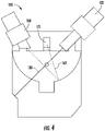
FIG. 4 is a cross-sectional illustration of a particulate detector ofFIG. 1 , in accordance with an embodiment of the disclosure; and -
FIG. 5 is a flow diagram illustrating a method of detecting air particulates and improving air quality, according to an embodiment of the present disclosure. - A detailed description of one or more embodiments of the disclosed system and method are presented herein by way of exemplification and not limitation with reference to the Figures.
- Detector units, such as optical fire detectors, gas detectors, etc., are used to detect a fire characteristic. An aspirated smoke detector is one type of fire detector that uses a suction unit, such as a blower or fan, that draws in air from the protected area. Typically, an aspirated smoke detection system continuously draws in air samples from several intake points of a pipe system, and analyzes the air particulate content. A range of air particulates may be present, such as combustion materials, oil mist, metallic powders, and microorganisms including bacteria, viruses, fungi, prions, viroid and spores. If a fire characteristic is recognized by a detector unit connected to the pipe system, an alarm is generally activated. However, if microorganisms are present in the air, they may be returned to the protected space untreated and potentially cause harm to building occupants. Described below is an air quality and particulate detection system that detects of the presence of air particulates and removes and/or treats harmful microorganisms from the environmental background using optical scattering, and at least one of a filter media and ultraviolet light before returning the air to a protected area.
- Referring now to
FIG. 1, FIG. 1 shows a schematic illustration of an air quality and aspiratedparticulate detection system 10, according to an embodiment of the present disclosure. The air quality and aspiratedparticulate detection system 10 includes an air quality andparticulate detector 40, one or more pipe runs 70 fluidly connected to the air quality andparticulate detector 40. The air quality and aspiratedparticulate detection system 10 may also include one or moresecondary particulate detectors 100 fluidly connected to the air quality andparticulate detector 40 through the one or more pipe runs 70. Each of the one or more pipe runs 70 initiate at afirst end 72 and terminates at asecond end 74. The air quality andparticulate detector 40, further described below, is fluidly connected to each of the one or more pipe runs 70 at thesecond end 74. Each of the one ormore pipe runs 70 includes one ormore sampling points 60 configured to allow air particulates entry into at least one of the one or more pipe runs. Thesampling points 60 may be an orifice and/or a nozzle in two non-limiting embodiments. - Turning to
FIG. 2 andFIG. 3 , with reference toFIG. 1 ,FIGs. 2 and3 each show a cross-section illustration of alternate embodiments of the air quality andparticulate detector 40. The air quality andparticulate detector 40 includes aparticulate detection chamber 41, and an adjacentair quality member 47. Theparticulate detection chamber 41 is in airflow communication with thesecond end 74 of the one or more pipe runs 70, via one ormore flow sensors 42. Ablower 43 draws air through the one ormore flow sensors 42 into theparticulate detection chamber 41. Additionally, theblower 43 transports air particulates from each of the one ormore sampling points 60 through the one or more pipe runs 70 to thesecond end 74, and into theparticulate detection chamber 41. Theblower 43 also transports the air particulates through each of thesecondary particulate detectors 100. Theblower 43 is adjacent to at least one of a media filter for removing particles such as dust, and other particles that are generally larger in size than a microorganism ("particle filter") 44, and alaser source 120, each located in theparticulate detection chamber 41. - The
laser source 120 may be configured to generate alaser 130 having a plurality of wavelengths and polarizations. Theparticulate detection chamber 41 may also include asensor 170 adjacent to thelaser source 120, the sensor configured to detect at least one of an amount of laser scatter, laser fluorescence or light generated from nonlinear optical effects in response to interaction of thelaser 130 and air particulates. The air quality andparticulate detector 40 may also be configured to determine anidentity 210 of the air particulate in response to at least one of the amount of light scatter and the laser fluorescence. For example, light scatter and/or laser fluorescence may help identify smoke and combustion materials. Once theidentity 210 of the air particulate is determined, the air quality andparticulate detector 40 is configured to activate analarm 359 in response to theidentity 210 of the air particulate. The alarm may be audible and/or visual. - As illustrated in
FIG. 3 , the air quality andparticulate detector 40 may also include alight source 160 configured to generate an ultraviolet light and/or an infrared light. The infrared light can be one or more wavelengths in a range of 700 nm to 30,000 nm, 700 nm to 4,000 nm, or more specifically, 700 nm to 1,500 nm. The ultraviolet light can be in a wavelength range of 25 nm to 480 nm, 160 nm to 480 nm or more specifically 375 nm to 480 nm. In addition, asensor 170 may be configured to detect an ultraviolet or infrared signature of an air particulate in response to interaction of theinfrared light 162 and the air particulate. The air quality andparticulate detector 40 may be configured to reflect light from thelight source 160 to thesensor 170. A single reflection, as shown inFIG. 3 , increases the path length and improves sensitivity to the air particulates of interest. Multiple passes can be utilized to increase the path length further to improve sensitivity to gases. Ultraviolet light may be utilized to identify microorganisms by looking for laser induced fluorescence. Infrared may be utilized to detect combustion, industrial and toxic particulates that have vibrational resonances in the infrared frequency band. The resonance causes light to be absorbed reducing the transmitted light and changing the signal that thesensor 170 observes. - The air quality and
particulate detector 40 may also be configured to determine an identity of 210 of an air particulate in response to the ultraviolet or infrared signature. Alocation 220, aconcentration 230, and/or anidentity 210 of the air particulate may be determined by algorithms that process the data collected fromsensor 170 in the air quality andparticulate detector 40. Thelocation 220 may depict the protectedarea 12 where the air particulate was detected. Theair particulate concentration 230 may depict a concentration of the air particulate in thelocation 220 and/or the protectedarea 12. Theair particulate concentration 230 may be a particulate concentration at a size. In order to determine thelocation 220, theconcentration 230, and/or theidentity 210 of the air particulate, data collected by the air quality andparticulate detector 40 may be compared to histogram values. The presence of a statistically significant value may initiate an alarm. The addition of multiple data points collected over time from different configures is used to identify the air particulates. A parallel decision-making approach based on support vector machine learning process compares the multiple data points to a multidimensional threshold. The result from the threshold is determination of the air particulates'identity 210. The air quality andparticulate detector 40 can be configured to transmit thelocation 220,concentration 230, and/oridentity 210 of the air particulate to auser device 300. An airparticulate concentration 230, of the air particulate is then displayed on a user interface of auser device 300, an alarm panel and/or a remote visualization tool. Auser device 300 may include but is not limited to a computing device, such as, for example, a desktop computer, a smart phone, a smart watch, a table, and/or any similar computing device known to one of skill in the art. - The
user device 300 is in electronic communication with the air quality andparticulate detector 40, and as discussed below may also be in electronic communication with one or moreair particulate detectors 100. Theuser device 300 may include a touch screen (not shown), mouse, keyboard, scroll wheel, physical button, or any input mechanism known to one of skill in the art. Theuser device 300 may include aprocessor 350,memory 352 andcommunication module 354 as shown inFIG. 1 . Theprocessor 350 can be any type or combination of computer processors, such as a microprocessor, microcontroller, digital signal processor, application specific integrated circuit, programmable logic device, and/or field programmable gate array. - The
memory 352 is an example of a non-transitory computer readable storage medium tangibly embodied in theuser device 300 including executable instructions stored therein, for instance, as firmware. Thecommunication module 354 may implement one or more communication protocols as described in further detail herein. Embodiments herein generate a graphical user interface on theuser device 300 through anapplication 355. The graphical user interface may display at least one of theair particulate concentration 230, thelocation 220 of the air particulate, and theidentity 210 of the air particulate. The air quality andparticulate detector 40 may be configured to activate analarm 359 in response to theidentity 210 of the air particulate. Thealarm 359 may be audible and/or visual. Thealarm 359 may emanate from theuser device 300. Theuser device 300 may include analert device 357 configured to activate thealarm 359. In three non-limiting examples, thealert device 357 may be a vibration motor, audio speaker, and/or display screen. - An
orifice 45 permits air to flow from theparticulate detection chamber 41 to theair quality member 47. In one non-limiting embodiment, theair quality member 47 includes achannel 46 having substantially parallel sides for operably coupling at least one filter media (e.g., a HEPA filter) 50 adjacent to theorifice 45, and one or more ultraviolet (UV) light emitting diodes (LEDs) 48 downstream from HEPA filter 50, and anexhaust pipe 49 downstream from theLEDs 48, for returning the airflow to the protectedarea 12. In another non-limiting embodiment, HEPA filter 50 may be positioned downstream of the LEDs 48 (not shown) and adjacent to the exhaust pipe. In yet another non-limiting embodiment, a HEPA filter 50 may be located at opposing ends ofchannel 46. The HEPA filter may be positioned transverse to channel 46, or in any orientation within the channel to accomplish adequate filtration. - The
channel 46 may be manufactured in whole or in part, from a metal or metal alloy. The metal or metal alloy may have a reflective surface, such as galvanized steel, or polished aluminum. In some embodiments, the metal or metal alloy will be heat conductive so that heat generated by theLEDs 48 may be rejected to air. In some embodiments, thechannel 46 may have a reflective lining, such as aluminum foil which also has good thermal conductive properties. - The HEPA filter 50 may be constructed from high efficiency particulate air (HEPA) filter material ("HEPA filter") having a range of MERV (minimum efficiency reporting value) ratings equal to or greater than MERV 6 and equal to or less than MERV 18, or more specifically, a rating range of
MERV 10 to MERV 15, inclusive. By way of example, and not limitation a HEPA filter 50 having a minimum rating of MERV 13, is at least 85% effective at capturing particles ranging in size from 1 µm to 3 µm (micron). Higher MERV ratings (e.g., MERV 14) may capture a higher percentage of particles. HEPA filters are more than 99.97% efficient at filtering human-generated aerosols such as virus SARS-CoV-2 which ranges in size from approximately 0.6 µm to 0.14 µm, or the bacteria S. aureus (MRSA) which ranges in size from approximately to 0.10 µm 0.25 µm. When the HEPA filter 50 is combined with ultraviolet LEDs lighting 48 discussed below, the removal rate (RR) of microorganisms may increase based in part on the exposure of the air particulate to ultraviolet light over a period of time, such that the quality of the air returned to the protectedspace 12 is improved. - The
LEDs 48 may be of any shape, and may be arranged in thechannel 46 in any pattern or configuration that provides the desired removal rate (RR). For example, LEDs may be one or more single LEDs, or an array, or may emit the same or differing light wavelengths. In one non-limiting embodiment, theLEDs 48 may be mounted on only one side of thechannel 46. In another non-limiting embodiment, as illustrated inFIGs. 2 and3 , LEDs may be mounted on both sides ofchannel 46. In one non-limiting embodiment,LEDs 48 generate an ultraviolet light in a wavelength range of 200 to 280 nm (e.g., UVC). In another non-limiting embodiment,LEDs 48 generate ultraviolet light in a wavelength range of 280 nm to 320 nm (e.g., UVB). As air and particulates flow throughchannel 46, shortwave ultraviolet radiation from the LEDs can inactivate a microorganisms. For example, at wavelengths below 250 nm, UVC is also referred to as UVGI (ultraviolet germicidal irradiation) which can penetrate the outer structure of a cell and alter the DNA molecule, preventing replication and causing cell death. As used by Federal agencies such as OSHA, NIOSH and the CDC, the term UVGI refers more specifically to UVC wavelength between 253 to 254 nm. - Generally, UVGI systems, are rated to describe performance. For example, a UVGI Rating Value (URV) is based on the UV dose produced, which is defined by the product of exposure time and irradiance. By way of example, a URV 13 rating refers to a dose of UVGI of 20 J/m2. Exposure time depends on airflow and the dimensions of the channel 46 (e.g., width, height, length) while irradiance depends on other factors described below. Exposure time (Et) may be determined as follows:


- Assuming the flow through
channel 46 is a turbulent mixture of air and particulates, the survival rate of any airborne microorganisms will be predicted by the standard exponential decay model, and the UVGI removal rate (RR) as follows: RR = 1 - e -kImEt where,
- k = UV rate constant, m2/J. This constant is related to the microorganism to be removed. For example, k for the SARS coronavirus is generally 0.01 m2/J.

- The irradiance field as a function of distance from the LED axis is a product of the surface irradiance and the view factor, where the surface irradiance is determined by dividing the UV power output by the surface area of a lamp, such as
LED 48. - The removal rate (RR) also considers the effect a diffuse enclosure may have in the total irradiation. For example, reflectivity and/or the length of
channel 46 may be used to determine LED power. In general, reflectivity will increase the average irradiance while channel length will increase the average UV dose by increasing exposure time. By way of example, and not limitation, the UVGI RR for an air quality andparticle detector 40 with a 6 liters/second airflow, thechannel 46 may have the following dimensions: 30cm (W) x 30cm (H) x 30 cm (L) or an total volume of 30 cm3 to achieve approximately 4.5 seconds exposure time (Et). The UVGI LED luminaire may be 25 cm (L), with diameter of approximately 5 cm. Considering thechannel 46 has a specular surface, and a microorganism were approximately 15 cm from the LED luminaire, considering a 20W lamp power output, the mean light irradiance at that distance would be 41.2 W/m2. In this example, the UVGI removal rate (RR) would be 84% for SARS Coronavirus and 100% for Influenza. - In one non-limiting embodiment, the removal rate (RR) may be improved when air quality and
particulate detector 40 utilizes the HEPA filter 50 andUV LEDs 48 in combination. For example, assuming an initial particulate population of 1M of the bacteria S. aureus (MRSA), a filter having a rating of MERV 13 typically achieves a removal rate of approximately 85%, reducing to the bacterial population to approximately 150,000. As this remaining population flows through theorifice 45 to thechannel 46, it is treated by the LEDs. Assuming the air quality andparticulate detector 40 also meets a UVR 13 rating, after LED irradiation a removal rate of approximately 99.9% may be achieved. The total removal rate then, is approximately 99.985%, reducing the particulate population from approximately 1M to 150. - Referring to
FIG. 4 , with continued refence toFIGs. 1-3 , the air quality and aspiratedparticulate detection system 10 may include one or more secondaryparticulate detectors 100, which may be located proximate the first end of one of the pipe runs 70 or may be located in the middle of apipe run 70. The secondaryparticulate detector 100 may be located proximate to at least one of the one or more sampling points 60. Advantageously, locating the secondaryparticulate detector 100 proximate to asampling point 60 reduces detection time by removing transport time, air particulate identification occurs close to thesample point 60 rather than waiting for the air particulate to travel from thesampling point 60 through thepipe run 70 to the air quality andparticulate detector 40. Also, advantageously, locating the secondaryparticulate detector 100 proximate to asampling point 60 allows for identification of alocation 220 of the air particulate. For example, a secondaryparticulate detector 100 may be located in each protectedarea 12 of a building and the protectedarea 12 where smoke arises may be identified by which the secondaryparticulate detector 100 detects smoke. The secondaryparticulate detector 100 may be in wireless electronic communication with the air quality andparticulate detector 40 and may be powered by an independent power source (not shown), such as a battery. - The secondary
particulate detector 100 may be located in the same protectedarea 12 as the air quality andparticulate detector 40 as illustrated inFIG. 1 , or they may be located in different protected areas. For example, the secondaryparticulate detector 100 may be located in a first protected area and the air quality andparticulate detector 40 may be located in a second detection area separate from the first detection area. Advantageously, by locating the air quality andparticulate detector 40 in a second detection area different from the first detection area, noise from theblower 43 may be reduced in the first protected area while maintaining quick particulate identification capability by the secondaryparticulate detector 100 in the first protected area. - The secondary
particulate detector 100 may, similar to the air quality andparticulate detector 40, include alaser source 120 configured to generate alaser 130 having a plurality of wavelengths and polarizations. The secondaryparticulate detector 100 may also include asensor 170 adjacent to thelaser source 120, the sensor configured to detect at least one of an amount of laser scatter, laser fluorescence or light generated from nonlinear optical effects in response to interaction of thelaser 130 and air particulates. The secondaryparticulate detector 100 may also be configured to determine anidentity 210 of the air particulate in response to at least one of the amount of light scatter and the laser fluorescence, and once theidentity 210 of the air particulate is determined, may be configured to activate an alarm in response to theidentity 210 of the air particulate. The alarm may be audible and/or visual. The secondaryparticulate detector 100 may also include alight source 160 configured to generate an ultraviolet light and/or an infrared light as described above. - As described above, the secondary
particulate detector 100 may also be configured to determine anidentity 210 of an air particulate in response to the ultraviolet or infrared signature, such that alocation 220, aconcentration 230, and/or anidentity 210 of the air particulate may be determined by algorithms that process the data collected fromsensor 170. The secondaryparticulate detector 100 can also be configured to transmit thelocation 220,concentration 230, and/oridentity 210 of the air particulate to auser device 300, each as described above. - Referring now to
FIG. 5 with continued reference toFIGs. 1-4 .FIG. 5 shows a flow diagram illustrating a method 500 of operating an air quality and particulate system, in accordance with embodiments of the disclosure. An air quality andparticulate detection system 10 includes an air quality and particulate detector 40 (FIGs. 2 ,3 ) comprising aparticulate detection chamber 41 in fluid communication via anorifice 45 with an adjacentair quality member 47. Theparticulate detection chamber 41 may include ablower 43 adjacent to aparticle filter 44 and alaser source 120. In some embodiments, theparticulate detection chamber 41 may also include ablower 43 adjacent to an infraredlight source 160 configured to generate an infrared light, and to a 170 configured to detect an infrared signature of an air particulate in response to interaction of the infrared light and the air particulate. The air quality member includes achannel 46 having substantially parallel sides for operably coupling a HEPA filter 50 adjacent and substantially parallel to theorifice 45, and for operably coupling one or more ultraviolet light emitting diodes (LEDs) 48 upstream from the HEPA filter, and anexhaust pipe 49 for returning treated air to a protectedarea 12. One or more pipe runs 70 are fluidly connected to theparticulate detection chamber 41. The one or more pipe runs includes one or more sampling points 60 configured to allow air particulate entry from the protectedarea 12, into at least one of the one or more pipe runs. - The method begins at 502 with allowing air particulate entry from an airflow of a protected
area 12 into one or more pipe runs 70 through one or more sampling points 60 in the airflow, wherein each of the one or more pipe runs initiate at afirst end 72 and terminate at asecond end 74. Atblock 504, the method includes conveying the air particulate in the airflow from thesecond end 74 to theparticulate detection chamber 41. - At
block 506, the method includes detecting the air particulate in the particulate detection chamber and separating the air particulate from the airflow; In theparticulate detection chamber 41, airflow and air particulates interact with theparticulate filter 44. A portion of the particulate is separated from the airflow by theparticulate filter 44. In general, the particulate filter is not a HEPA filter. - At
block 508, the method includes conveying the airflow through a HEPA filter 50. Thechannel 44 of the air quality member, may have one or more HEPA filters 50. In some embodiments, the air may flow through a HEPA filter 50 adjacent to the particulatedetection chamber orifice 45 and/or it may flow through a HEPA filter 50 adjacent to theexhaust pipe 49. In one non-limiting embodiment, the HEPA filter material has a MERV rating equal to or greater than MERV 6 and equal to or less than MERV 18, or more specifically, a rating range ofMERV 10 to MERV 15, inclusive. In general, HEPA filters within the stated range can be highly efficient at removing microorganisms, including living and non-living biological entities (e.g., viruses) from an airflow, as described above. - At
block 510, the method includes treating the airflow, which may include microorganisms such as living and non-living biological entities (e.g., viruses), with ultraviolet germicidal radiation from one or more light emitting diodes (LEDs) 48. The ultraviolet LEDs may be arranged in any manner so as to effectively treat the airflow. In one non-limiting embodiment, the one or more LEDs generate light in a wavelength range equal to or greater than 200 nm and equal to or less than 320 nm. At block 514, the method includes returning the airflow to the protectedarea 12 via theexhaust pipe 49. - While the above description has described the flow process of
FIG. 5 in a particular order, it should be appreciated that unless otherwise specifically required in the attached claims that the ordering of the steps may be varied. - As described above, embodiments can be in the form of processor-implemented processes and devices for practicing those processes, such as a processor. Embodiments can also be in the form of computer program code containing instructions embodied in tangible media, such as network cloud storage, SD cards, flash drives, floppy diskettes, CD ROMs, hard drives, or any other computer-readable storage medium, wherein, when the computer program code is loaded into and executed by a computer, the computer becomes a device for practicing the embodiments. Embodiments can also be in the form of computer program code, for example, whether stored in a storage medium, loaded into and/or executed by a computer, or transmitted over some transmission medium, loaded into and/or executed by a computer, or transmitted over some transmission medium, such as over electrical wiring or cabling, through fiber optics, or via electromagnetic radiation, wherein, when the computer program code is loaded into an executed by a computer, the computer becomes a device for practicing the embodiments. When implemented on a general-purpose microprocessor, the computer program code segments configure the microprocessor to create specific logic circuits.
- The term "about" is intended to include the degree of error associated with measurement of the particular quantity based upon the equipment available at the time of filing the application. For example, "about" can include a range of ± 8% or 5%, or 2% of a given value.
- The terminology used herein is for the purpose of describing particular embodiments only and is not intended to be limiting of the present disclosure. As used herein, the singular forms "a", "an" and "the" are intended to include the plural forms as well, unless the context clearly indicates otherwise. It will be further understood that the terms "comprises" and/or "comprising," when used in this specification, specify the presence of stated features, integers, steps, operations, elements, and/or components, but do not preclude the presence or addition of one or more other features, integers, steps, operations, element components, and/or groups thereof.
- While the present invention has been described with reference to an exemplary embodiment or embodiments, it will be understood by those skilled in the art that various changes may be made, and equivalents may be substituted for elements thereof without departing from the scope of the present invention as defined by the claims. In addition, many modifications may be made to adapt a particular situation or material to the teachings of the present invention without departing from the essential scope thereof as defined by the claims. Therefore, it is intended that the present invention not be limited to the particular embodiment disclosed as the best mode contemplated for carrying out this present invention, but that the present invention will include all embodiments falling within the scope of the claims.
Claims (15)
- An air quality and particulate detection system (10) comprising:an air quality and particulate detector (40) comprising a particulate detection chamber (41) in fluid communication via an orifice (45) with an adjacent air quality member (47),the particulate detection chamber comprising a blower (43) adjacent to a particle filter (44) and a laser source (120), andthe air quality member comprising:a channel (46) having substantially parallel sides for operably coupling a HEPA filter (50) adjacent and substantially parallel to the orifice, and for operably coupling one or more ultraviolet light emitting diodes (LEDs) (48) downstream from the HEPA filter, andan exhaust pipe (49) for returning treated air to a protected area (12); andone or more pipe runs (70) fluidly connected to the particulate detection chamber, wherein each of the one or more pipe runs includes one or more sampling points (60) configured to allow air particulate entry from the protected area, into at least one of the one or more pipe runs.
- The air quality and particulate detection system of claim 1, comprising one or more secondary particulate detectors (100) fluidly connected to the air quality and particulate detector (40) through the one or more pipe runs (70).
- The air quality and particulate detection system of claim 1 or 2, wherein the HEPA filter (50) has a designation equal to or greater than MERV 6 and equal to or less than MERV 18;
and/or
wherein the ultraviolet LEDs (48) generate light in a wavelength range equal to or greater than 200 nm and equal to or less than 320 nm. - The air quality and particulate detection system of any preceding claim, wherein the laser source (120) is configured to generate a laser (130) having a plurality of wavelengths.
- The air quality and particulate detection system of claim 4, wherein the laser source (120) is adjacent to a sensor (170), the sensor configured to detect at least one of an amount of laser scatter and laser fluorescence in response to interaction of the laser (130) and air particulates.
- The air quality and particulate detection system of claim 4 or 5, wherein the blower (43) is adjacent to: an infrared light source (160) configured to generate an infrared light (162), and to a sensor (170) configured to detect an infrared signature of an air particulate in response to interaction of the infrared light and the air particulate.
- The air quality and particulate detection system of claim 5 or 6, wherein the air quality and particulate detector (40) is configured to determine an identity (210) of the air particulate in response to at least one of an amount of light scatter and the laser fluorescence;
optionally wherein the air quality and particulate detector (40) is configured to activate an alarm (359) in response to the identity (210) of the air particulate. - The air quality and particulate detection system of claim 6 or 7 when dependent on claim 6, wherein the air quality and particulate detector (40) is configured to transmit the infrared signature to the air quality and particulate detection system.
- An air quality and particulate detector (40) comprising a particulate detection chamber in fluid communication via an orifice (45) with an adjacent air quality member (47), wherein:the particulate detection chamber (41) comprises a blower (43) adjacent to a particle filter (44) and a laser source (120), andthe air quality member comprises a channel (46) having substantially parallel sides for operably coupling a HEPA filter (50) adjacent and substantially parallel to the orifice (45), and for operably coupling one or more ultraviolet light emitting diodes (LEDs) upstream from the HEPA filter, and an exhaust pipe for returning treated air to a protected area.
- The air quality and particulate detector of claim 9, wherein the HEPA filter (50) has a designation equal to or greater than MERV 6 and equal to or less than MERV 18; and/or wherein the ultraviolet LEDs (48) generate light in the wavelength range of 200 to 320 nm.
- The air quality and particulate detector of claim 9 or 10, wherein the laser source (120) is configured to generate a laser (130) having a plurality of wavelengths.
- The air quality and particulate detector of claim 11, wherein the laser source (120) is adjacent to a sensor (170), the sensor configured to detect at least one of an amount of laser scatter and laser fluorescence in response to interaction of the laser (130) and air particulates.
- A method (500) of operating an air quality and particulate system (10), the method comprising:allowing (502) air particulate entry from an airflow of a protected area (12) into one or more pipe runs (70) through one or more sampling points (60) in the airflow, wherein each of the one or more pipe runs initiate at a first end (72) and terminate at a second end (74);conveying (504) the air particulate in the airflow from the second end (74) to a particulate detection chamber (41) of an operably coupled air quality and particulate detector (40);detecting (506) the air particulate in the particulate detection chamber and separating the air particulate from the airflow;conveying (508) the airflow through a particulate detection chamber orifice (45) and through a HEPA filter (50) positioned in an adjacent air quality member (47);treating (510) the airflow in the air quality member, with ultraviolet germicidal radiation from one or more ultraviolet light emitting diodes (LEDs) (48); andreturning (512) the airflow to the protected area via an exhaust pipe (49).
- The method of claim 13, wherein the HEPA filter (50) has a designation equal to or greater than MERV 6 and equal to or less than MERV 18.
- The method of claim 13 or 14, wherein the one or more LEDs (48) generate light in the wavelength range of 200 to 320 nm.
Applications Claiming Priority (1)
| Application Number | Priority Date | Filing Date | Title |
|---|---|---|---|
| US202063198712P | 2020-11-06 | 2020-11-06 |
Publications (2)
| Publication Number | Publication Date |
|---|---|
| EP3995806A1 true EP3995806A1 (en) | 2022-05-11 |
| EP3995806B1 EP3995806B1 (en) | 2025-09-10 |
Family
ID=78789618
Family Applications (1)
| Application Number | Title | Priority Date | Filing Date |
|---|---|---|---|
| EP21206803.5A Active EP3995806B1 (en) | 2020-11-06 | 2021-11-05 | Air quality and particulate detection system |
Country Status (3)
| Country | Link |
|---|---|
| US (1) | US12281974B2 (en) |
| EP (1) | EP3995806B1 (en) |
| CN (1) | CN114441392A (en) |
Cited By (1)
| Publication number | Priority date | Publication date | Assignee | Title |
|---|---|---|---|---|
| US20230117469A1 (en) * | 2021-10-20 | 2023-04-20 | Wynd Technologies, Inc. | Particulate detection, counting, and identification |
Families Citing this family (1)
| Publication number | Priority date | Publication date | Assignee | Title |
|---|---|---|---|---|
| CN115855775B (en) * | 2023-02-17 | 2023-05-23 | 深圳山田电器有限公司 | Air purifier testing arrangement based on internet |
Citations (4)
| Publication number | Priority date | Publication date | Assignee | Title |
|---|---|---|---|---|
| EP1739405A1 (en) * | 2005-06-28 | 2007-01-03 | Hirayama Setsubi Kabushiki Kaisha | Method and apparatus for detecting and removing airborne microbes |
| US20170016638A1 (en) * | 2013-12-13 | 2017-01-19 | Coway Co., Ltd | Bio Sensor and Air Cleaner Having Same |
| US20180154297A1 (en) * | 2016-12-06 | 2018-06-07 | Fellowes, Inc. | Air purifier with intelligent sensors and airflow |
| EP3483585A1 (en) * | 2017-11-13 | 2019-05-15 | Carrier Corporation | Air particulate detection system |
Family Cites Families (23)
| Publication number | Priority date | Publication date | Assignee | Title |
|---|---|---|---|---|
| US5240478A (en) * | 1992-06-26 | 1993-08-31 | Messina Gary D | Self-contained, portable room air treatment apparatus and method therefore |
| US6792795B2 (en) * | 2001-10-26 | 2004-09-21 | Lockheed Martin Corporation | System and method for detecting hazardous materials using agitation |
| TWI230630B (en) | 2003-08-26 | 2005-04-11 | Jie Ouyang | Air filtering/cleaning device and control method thereof |
| US7151264B2 (en) | 2004-12-21 | 2006-12-19 | Ranco Incorporated Of Delaware | Inline air handler system and associated method of use |
| US7820100B2 (en) * | 2007-05-17 | 2010-10-26 | Garfield Industries, Inc. | System and method for photocatalytic oxidation air filtration using a substrate with photocatalyst particles powder coated thereon |
| US7824626B2 (en) * | 2007-09-27 | 2010-11-02 | Applied Nanotech Holdings, Inc. | Air handler and purifier |
| CN101551143B (en) * | 2008-04-02 | 2011-09-28 | 展晶科技(深圳)有限公司 | Air purifier |
| DE102009011846B4 (en) | 2009-03-05 | 2015-07-30 | MaxDeTec AG | Analytical methods and devices for fluids |
| US9310088B2 (en) * | 2009-07-17 | 2016-04-12 | Technical University Of Denmark | Device and method for reducing spread of microorganisms and airborne health hazardous matter and/or for protection from microorganisms and airborne health hazardous matter |
| EP2542347A4 (en) | 2010-03-05 | 2016-05-11 | Xtralis Technologies Ltd | particle |
| US8518137B2 (en) * | 2010-09-21 | 2013-08-27 | Raytheon Company | Miniature active standoff chamber |
| US8974565B2 (en) * | 2011-09-05 | 2015-03-10 | Michael Cecchi | Air filtration and air purification apparatus |
| JP6438399B2 (en) | 2012-10-16 | 2018-12-12 | ギャレット・サーマル・システムズ・リミテッドGarrett Thermal Systems Limited | Addressability in particle detection |
| MY179786A (en) | 2013-06-03 | 2020-11-14 | Xtralis Technologies Ltd | Particle detection system and related methods |
| US9597627B2 (en) * | 2014-10-19 | 2017-03-21 | Wei Zhang (William) | Regenerative air purification system and method |
| US9791354B2 (en) | 2015-01-26 | 2017-10-17 | Honeywell International Inc. | Inline pre-filter for aspirated detectors |
| CN205428117U (en) | 2015-12-08 | 2016-08-03 | 中国航空规划设计研究总院有限公司 | A collector box for fire alarm system |
| US10746426B2 (en) | 2015-12-08 | 2020-08-18 | Carrier Corporation | Agent detection system assisted by a building subsystem |
| US9921144B2 (en) * | 2016-06-29 | 2018-03-20 | Honeywell International Inc. | Particulate matter detector |
| US11260143B2 (en) * | 2016-11-22 | 2022-03-01 | Seoul Viosys Co., Ltd. | Air purifier |
| US11536476B2 (en) * | 2020-05-12 | 2022-12-27 | Johnson Controls Tyco IP Holdings LLP | Building system with flexible facility operation |
| US12097310B2 (en) * | 2020-06-19 | 2024-09-24 | The Boeing Company | Apparatus and method for irradiating air in an air circulation system of a vehicle |
| US20220105457A1 (en) * | 2020-10-01 | 2022-04-07 | Timilon Corporation | Air purification system |
-
2021
- 2021-10-29 US US17/452,898 patent/US12281974B2/en active Active
- 2021-11-05 EP EP21206803.5A patent/EP3995806B1/en active Active
- 2021-11-05 CN CN202111305053.0A patent/CN114441392A/en active Pending
Patent Citations (4)
| Publication number | Priority date | Publication date | Assignee | Title |
|---|---|---|---|---|
| EP1739405A1 (en) * | 2005-06-28 | 2007-01-03 | Hirayama Setsubi Kabushiki Kaisha | Method and apparatus for detecting and removing airborne microbes |
| US20170016638A1 (en) * | 2013-12-13 | 2017-01-19 | Coway Co., Ltd | Bio Sensor and Air Cleaner Having Same |
| US20180154297A1 (en) * | 2016-12-06 | 2018-06-07 | Fellowes, Inc. | Air purifier with intelligent sensors and airflow |
| EP3483585A1 (en) * | 2017-11-13 | 2019-05-15 | Carrier Corporation | Air particulate detection system |
Cited By (2)
| Publication number | Priority date | Publication date | Assignee | Title |
|---|---|---|---|---|
| US20230117469A1 (en) * | 2021-10-20 | 2023-04-20 | Wynd Technologies, Inc. | Particulate detection, counting, and identification |
| US12306104B2 (en) * | 2021-10-20 | 2025-05-20 | Wynd Technologies, Inc. | Particulate detection, counting, and identification |
Also Published As
| Publication number | Publication date |
|---|---|
| US20220146397A1 (en) | 2022-05-12 |
| CN114441392A (en) | 2022-05-06 |
| US12281974B2 (en) | 2025-04-22 |
| EP3995806B1 (en) | 2025-09-10 |
Similar Documents
| Publication | Publication Date | Title |
|---|---|---|
| JP5112312B2 (en) | Pathogen and particulate detection system and detection method | |
| EP3995806B1 (en) | Air quality and particulate detection system | |
| KR101170859B1 (en) | Pathogen and particle detector system and method | |
| US20060071803A1 (en) | Pathogen detector system and method | |
| KR102612777B1 (en) | Air treatment systems and methods | |
| EP3483585B1 (en) | Air particulate detection system | |
| US7242009B1 (en) | Methods and systems for signal processing in particle detection systems | |
| US20220196268A1 (en) | Air sensing and purification systems | |
| US10082467B2 (en) | Menthol detection on tobacco | |
| US11828687B2 (en) | Detection of a clogged filter in an aspirating detection system | |
| WO2022047340A1 (en) | Air sensing and purification systems | |
| EP4299996A1 (en) | Central controller for completely cleaning indoor air pollution | |
| EP4445989A1 (en) | Method for purifying air pollution in indoor space to level close to zero | |
| US20240003563A1 (en) | Method for detecting and cleaning indoor air pollution | |
| TWI424154B (en) | Pathogen and particle detector system and method | |
| US12055466B1 (en) | Devices, systems and methods relating to high speed postal monitoring | |
| US20240003573A1 (en) | Conception of locating and completely cleaning indoor air pollution | |
| EP4163398B1 (en) | Method and system for real-time detection of biological agents suspended in the air | |
| CN113390767A (en) | Dust detection device and dust detection method | |
| CN116168503A (en) | An aspirating smoke detector | |
| KR20240067650A (en) | An air sterilization cleaning device that removes pollutants that fuse the internet of things (iot) function | |
| Dable et al. | Recent testing and performance improvements of a fluorescence-based biological aerosol sensor | |
| Langer et al. | Ventilating-air change rate versus particulate contaminant spread | |
| HK1082041A (en) | Airborne pathogen detector system and method |
Legal Events
| Date | Code | Title | Description |
|---|---|---|---|
| PUAI | Public reference made under article 153(3) epc to a published international application that has entered the european phase |
Free format text: ORIGINAL CODE: 0009012 |
|
| STAA | Information on the status of an ep patent application or granted ep patent |
Free format text: STATUS: THE APPLICATION HAS BEEN PUBLISHED |
|
| AK | Designated contracting states |
Kind code of ref document: A1 Designated state(s): AL AT BE BG CH CY CZ DE DK EE ES FI FR GB GR HR HU IE IS IT LI LT LU LV MC MK MT NL NO PL PT RO RS SE SI SK SM TR |
|
| STAA | Information on the status of an ep patent application or granted ep patent |
Free format text: STATUS: REQUEST FOR EXAMINATION WAS MADE |
|
| 17P | Request for examination filed |
Effective date: 20221111 |
|
| RBV | Designated contracting states (corrected) |
Designated state(s): AL AT BE BG CH CY CZ DE DK EE ES FI FR GB GR HR HU IE IS IT LI LT LU LV MC MK MT NL NO PL PT RO RS SE SI SK SM TR |
|
| STAA | Information on the status of an ep patent application or granted ep patent |
Free format text: STATUS: EXAMINATION IS IN PROGRESS |
|
| 17Q | First examination report despatched |
Effective date: 20241028 |
|
| REG | Reference to a national code |
Ref legal event code: R079 Free format text: PREVIOUS MAIN CLASS: G01N0001220000 Ref country code: DE Ref legal event code: R079 Ref document number: 602021038183 Country of ref document: DE Free format text: PREVIOUS MAIN CLASS: G01N0001220000 Ipc: G01N0015140000 |
|
| GRAP | Despatch of communication of intention to grant a patent |
Free format text: ORIGINAL CODE: EPIDOSNIGR1 |
|
| STAA | Information on the status of an ep patent application or granted ep patent |
Free format text: STATUS: GRANT OF PATENT IS INTENDED |
|
| RIC1 | Information provided on ipc code assigned before grant |
Ipc: G01N 15/00 20060101ALN20250319BHEP Ipc: F24F 110/64 20180101ALN20250319BHEP Ipc: F24F 110/50 20180101ALN20250319BHEP Ipc: G01N 1/24 20060101ALN20250319BHEP Ipc: F24F 8/22 20210101ALI20250319BHEP Ipc: G01N 1/22 20060101ALI20250319BHEP Ipc: G01N 15/01 20240101ALI20250319BHEP Ipc: G01N 15/1434 20240101ALI20250319BHEP Ipc: G01N 15/14 20060101AFI20250319BHEP |
|
| INTG | Intention to grant announced |
Effective date: 20250331 |
|
| GRAS | Grant fee paid |
Free format text: ORIGINAL CODE: EPIDOSNIGR3 |
|
| GRAA | (expected) grant |
Free format text: ORIGINAL CODE: 0009210 |
|
| STAA | Information on the status of an ep patent application or granted ep patent |
Free format text: STATUS: THE PATENT HAS BEEN GRANTED |
|
| AK | Designated contracting states |
Kind code of ref document: B1 Designated state(s): AL AT BE BG CH CY CZ DE DK EE ES FI FR GB GR HR HU IE IS IT LI LT LU LV MC MK MT NL NO PL PT RO RS SE SI SK SM TR |
|
| REG | Reference to a national code |
Ref country code: GB Ref legal event code: FG4D |
|
| REG | Reference to a national code |
Ref country code: CH Ref legal event code: EP |
|
| REG | Reference to a national code |
Ref country code: DE Ref legal event code: R096 Ref document number: 602021038183 Country of ref document: DE |
|
| REG | Reference to a national code |
Ref country code: IE Ref legal event code: FG4D |
|
| PGFP | Annual fee paid to national office [announced via postgrant information from national office to epo] |
Ref country code: DE Payment date: 20251022 Year of fee payment: 5 |
|
| PGFP | Annual fee paid to national office [announced via postgrant information from national office to epo] |
Ref country code: GB Payment date: 20251023 Year of fee payment: 5 |
|
| PG25 | Lapsed in a contracting state [announced via postgrant information from national office to epo] |
Ref country code: NO Free format text: LAPSE BECAUSE OF FAILURE TO SUBMIT A TRANSLATION OF THE DESCRIPTION OR TO PAY THE FEE WITHIN THE PRESCRIBED TIME-LIMIT Effective date: 20251210 |
|
| REG | Reference to a national code |
Ref country code: LT Ref legal event code: MG9D |
|
| PGFP | Annual fee paid to national office [announced via postgrant information from national office to epo] |
Ref country code: AT Payment date: 20260113 Year of fee payment: 5 |
|
| PG25 | Lapsed in a contracting state [announced via postgrant information from national office to epo] |
Ref country code: FI Free format text: LAPSE BECAUSE OF FAILURE TO SUBMIT A TRANSLATION OF THE DESCRIPTION OR TO PAY THE FEE WITHIN THE PRESCRIBED TIME-LIMIT Effective date: 20250910 |
|
| REG | Reference to a national code |
Ref country code: NL Ref legal event code: MP Effective date: 20250910 |
|
| PG25 | Lapsed in a contracting state [announced via postgrant information from national office to epo] |
Ref country code: HR Free format text: LAPSE BECAUSE OF FAILURE TO SUBMIT A TRANSLATION OF THE DESCRIPTION OR TO PAY THE FEE WITHIN THE PRESCRIBED TIME-LIMIT Effective date: 20250910 |
|
| PGFP | Annual fee paid to national office [announced via postgrant information from national office to epo] |
Ref country code: FR Payment date: 20251023 Year of fee payment: 5 |
|
| PG25 | Lapsed in a contracting state [announced via postgrant information from national office to epo] |
Ref country code: GR Free format text: LAPSE BECAUSE OF FAILURE TO SUBMIT A TRANSLATION OF THE DESCRIPTION OR TO PAY THE FEE WITHIN THE PRESCRIBED TIME-LIMIT Effective date: 20251211 |
|
| PG25 | Lapsed in a contracting state [announced via postgrant information from national office to epo] |
Ref country code: SE Free format text: LAPSE BECAUSE OF FAILURE TO SUBMIT A TRANSLATION OF THE DESCRIPTION OR TO PAY THE FEE WITHIN THE PRESCRIBED TIME-LIMIT Effective date: 20250910 |
|
| PG25 | Lapsed in a contracting state [announced via postgrant information from national office to epo] |
Ref country code: LV Free format text: LAPSE BECAUSE OF FAILURE TO SUBMIT A TRANSLATION OF THE DESCRIPTION OR TO PAY THE FEE WITHIN THE PRESCRIBED TIME-LIMIT Effective date: 20250910 |
|
| PG25 | Lapsed in a contracting state [announced via postgrant information from national office to epo] |
Ref country code: BG Free format text: LAPSE BECAUSE OF FAILURE TO SUBMIT A TRANSLATION OF THE DESCRIPTION OR TO PAY THE FEE WITHIN THE PRESCRIBED TIME-LIMIT Effective date: 20250910 Ref country code: PL Free format text: LAPSE BECAUSE OF FAILURE TO SUBMIT A TRANSLATION OF THE DESCRIPTION OR TO PAY THE FEE WITHIN THE PRESCRIBED TIME-LIMIT Effective date: 20250910 |
|
| PG25 | Lapsed in a contracting state [announced via postgrant information from national office to epo] |
Ref country code: RS Free format text: LAPSE BECAUSE OF FAILURE TO SUBMIT A TRANSLATION OF THE DESCRIPTION OR TO PAY THE FEE WITHIN THE PRESCRIBED TIME-LIMIT Effective date: 20251210 |
|
| PG25 | Lapsed in a contracting state [announced via postgrant information from national office to epo] |
Ref country code: ES Free format text: LAPSE BECAUSE OF FAILURE TO SUBMIT A TRANSLATION OF THE DESCRIPTION OR TO PAY THE FEE WITHIN THE PRESCRIBED TIME-LIMIT Effective date: 20250910 |
|
| REG | Reference to a national code |
Ref country code: AT Ref legal event code: MK05 Ref document number: 1836346 Country of ref document: AT Kind code of ref document: T Effective date: 20250910 |
|
| PG25 | Lapsed in a contracting state [announced via postgrant information from national office to epo] |
Ref country code: NL Free format text: LAPSE BECAUSE OF FAILURE TO SUBMIT A TRANSLATION OF THE DESCRIPTION OR TO PAY THE FEE WITHIN THE PRESCRIBED TIME-LIMIT Effective date: 20250910 |
|
| PG25 | Lapsed in a contracting state [announced via postgrant information from national office to epo] |
Ref country code: SM Free format text: LAPSE BECAUSE OF FAILURE TO SUBMIT A TRANSLATION OF THE DESCRIPTION OR TO PAY THE FEE WITHIN THE PRESCRIBED TIME-LIMIT Effective date: 20250910 |
|
| PG25 | Lapsed in a contracting state [announced via postgrant information from national office to epo] |
Ref country code: AT Free format text: LAPSE BECAUSE OF FAILURE TO SUBMIT A TRANSLATION OF THE DESCRIPTION OR TO PAY THE FEE WITHIN THE PRESCRIBED TIME-LIMIT Effective date: 20250910 |
|
| PG25 | Lapsed in a contracting state [announced via postgrant information from national office to epo] |
Ref country code: RO Free format text: LAPSE BECAUSE OF FAILURE TO SUBMIT A TRANSLATION OF THE DESCRIPTION OR TO PAY THE FEE WITHIN THE PRESCRIBED TIME-LIMIT Effective date: 20250910 Ref country code: IT Free format text: LAPSE BECAUSE OF FAILURE TO SUBMIT A TRANSLATION OF THE DESCRIPTION OR TO PAY THE FEE WITHIN THE PRESCRIBED TIME-LIMIT Effective date: 20250910 |
|
| PG25 | Lapsed in a contracting state [announced via postgrant information from national office to epo] |
Ref country code: IS Free format text: LAPSE BECAUSE OF FAILURE TO SUBMIT A TRANSLATION OF THE DESCRIPTION OR TO PAY THE FEE WITHIN THE PRESCRIBED TIME-LIMIT Effective date: 20260110 |
|
| PG25 | Lapsed in a contracting state [announced via postgrant information from national office to epo] |
Ref country code: PT Free format text: LAPSE BECAUSE OF FAILURE TO SUBMIT A TRANSLATION OF THE DESCRIPTION OR TO PAY THE FEE WITHIN THE PRESCRIBED TIME-LIMIT Effective date: 20260112 Ref country code: CZ Free format text: LAPSE BECAUSE OF FAILURE TO SUBMIT A TRANSLATION OF THE DESCRIPTION OR TO PAY THE FEE WITHIN THE PRESCRIBED TIME-LIMIT Effective date: 20250910 |
|
| PG25 | Lapsed in a contracting state [announced via postgrant information from national office to epo] |
Ref country code: SK Free format text: LAPSE BECAUSE OF FAILURE TO SUBMIT A TRANSLATION OF THE DESCRIPTION OR TO PAY THE FEE WITHIN THE PRESCRIBED TIME-LIMIT Effective date: 20250910 Ref country code: EE Free format text: LAPSE BECAUSE OF FAILURE TO SUBMIT A TRANSLATION OF THE DESCRIPTION OR TO PAY THE FEE WITHIN THE PRESCRIBED TIME-LIMIT Effective date: 20250910 |