EP3995764A1 - Climatization container - Google Patents
Climatization container Download PDFInfo
- Publication number
- EP3995764A1 EP3995764A1 EP21195057.1A EP21195057A EP3995764A1 EP 3995764 A1 EP3995764 A1 EP 3995764A1 EP 21195057 A EP21195057 A EP 21195057A EP 3995764 A1 EP3995764 A1 EP 3995764A1
- Authority
- EP
- European Patent Office
- Prior art keywords
- duct
- evaporator
- air
- compartment
- climatization
- Prior art date
- Legal status (The legal status is an assumption and is not a legal conclusion. Google has not performed a legal analysis and makes no representation as to the accuracy of the status listed.)
- Granted
Links
Images




Classifications
-
- F—MECHANICAL ENGINEERING; LIGHTING; HEATING; WEAPONS; BLASTING
- F25—REFRIGERATION OR COOLING; COMBINED HEATING AND REFRIGERATION SYSTEMS; HEAT PUMP SYSTEMS; MANUFACTURE OR STORAGE OF ICE; LIQUEFACTION SOLIDIFICATION OF GASES
- F25D—REFRIGERATORS; COLD ROOMS; ICE-BOXES; COOLING OR FREEZING APPARATUS NOT OTHERWISE PROVIDED FOR
- F25D17/00—Arrangements for circulating cooling fluids; Arrangements for circulating gas, e.g. air, within refrigerated spaces
- F25D17/04—Arrangements for circulating cooling fluids; Arrangements for circulating gas, e.g. air, within refrigerated spaces for circulating air, e.g. by convection
- F25D17/06—Arrangements for circulating cooling fluids; Arrangements for circulating gas, e.g. air, within refrigerated spaces for circulating air, e.g. by convection by forced circulation
-
- F—MECHANICAL ENGINEERING; LIGHTING; HEATING; WEAPONS; BLASTING
- F25—REFRIGERATION OR COOLING; COMBINED HEATING AND REFRIGERATION SYSTEMS; HEAT PUMP SYSTEMS; MANUFACTURE OR STORAGE OF ICE; LIQUEFACTION SOLIDIFICATION OF GASES
- F25D—REFRIGERATORS; COLD ROOMS; ICE-BOXES; COOLING OR FREEZING APPARATUS NOT OTHERWISE PROVIDED FOR
- F25D2317/00—Details or arrangements for circulating cooling fluids; Details or arrangements for circulating gas, e.g. air, within refrigerated spaces, not provided for in other groups of this subclass
- F25D2317/06—Details or arrangements for circulating cooling fluids; Details or arrangements for circulating gas, e.g. air, within refrigerated spaces, not provided for in other groups of this subclass with forced air circulation
- F25D2317/063—Details or arrangements for circulating cooling fluids; Details or arrangements for circulating gas, e.g. air, within refrigerated spaces, not provided for in other groups of this subclass with forced air circulation with air guides
-
- F—MECHANICAL ENGINEERING; LIGHTING; HEATING; WEAPONS; BLASTING
- F25—REFRIGERATION OR COOLING; COMBINED HEATING AND REFRIGERATION SYSTEMS; HEAT PUMP SYSTEMS; MANUFACTURE OR STORAGE OF ICE; LIQUEFACTION SOLIDIFICATION OF GASES
- F25D—REFRIGERATORS; COLD ROOMS; ICE-BOXES; COOLING OR FREEZING APPARATUS NOT OTHERWISE PROVIDED FOR
- F25D2317/00—Details or arrangements for circulating cooling fluids; Details or arrangements for circulating gas, e.g. air, within refrigerated spaces, not provided for in other groups of this subclass
- F25D2317/06—Details or arrangements for circulating cooling fluids; Details or arrangements for circulating gas, e.g. air, within refrigerated spaces, not provided for in other groups of this subclass with forced air circulation
- F25D2317/066—Details or arrangements for circulating cooling fluids; Details or arrangements for circulating gas, e.g. air, within refrigerated spaces, not provided for in other groups of this subclass with forced air circulation characterised by the air supply
-
- F—MECHANICAL ENGINEERING; LIGHTING; HEATING; WEAPONS; BLASTING
- F25—REFRIGERATION OR COOLING; COMBINED HEATING AND REFRIGERATION SYSTEMS; HEAT PUMP SYSTEMS; MANUFACTURE OR STORAGE OF ICE; LIQUEFACTION SOLIDIFICATION OF GASES
- F25D—REFRIGERATORS; COLD ROOMS; ICE-BOXES; COOLING OR FREEZING APPARATUS NOT OTHERWISE PROVIDED FOR
- F25D2317/00—Details or arrangements for circulating cooling fluids; Details or arrangements for circulating gas, e.g. air, within refrigerated spaces, not provided for in other groups of this subclass
- F25D2317/06—Details or arrangements for circulating cooling fluids; Details or arrangements for circulating gas, e.g. air, within refrigerated spaces, not provided for in other groups of this subclass with forced air circulation
- F25D2317/067—Details or arrangements for circulating cooling fluids; Details or arrangements for circulating gas, e.g. air, within refrigerated spaces, not provided for in other groups of this subclass with forced air circulation characterised by air ducts
- F25D2317/0671—Inlet ducts
-
- F—MECHANICAL ENGINEERING; LIGHTING; HEATING; WEAPONS; BLASTING
- F25—REFRIGERATION OR COOLING; COMBINED HEATING AND REFRIGERATION SYSTEMS; HEAT PUMP SYSTEMS; MANUFACTURE OR STORAGE OF ICE; LIQUEFACTION SOLIDIFICATION OF GASES
- F25D—REFRIGERATORS; COLD ROOMS; ICE-BOXES; COOLING OR FREEZING APPARATUS NOT OTHERWISE PROVIDED FOR
- F25D2317/00—Details or arrangements for circulating cooling fluids; Details or arrangements for circulating gas, e.g. air, within refrigerated spaces, not provided for in other groups of this subclass
- F25D2317/06—Details or arrangements for circulating cooling fluids; Details or arrangements for circulating gas, e.g. air, within refrigerated spaces, not provided for in other groups of this subclass with forced air circulation
- F25D2317/068—Details or arrangements for circulating cooling fluids; Details or arrangements for circulating gas, e.g. air, within refrigerated spaces, not provided for in other groups of this subclass with forced air circulation characterised by the fans
- F25D2317/0682—Two or more fans
Definitions
- the present invention relates to a climatization container, for instance a refrigerator or a freezer.
- a climatization container comprises a container suitable for keeping contents stored therein under particular climatic conditions, for instance within a predetermined temperature or humidity range.
- Climatization containers are commonly used for storing products such as food and beverages.
- Particular examples include refrigerators and freezers where the primary requirement is to store food and beverages within a predetermined temperature range.
- a climatization container for instance a refrigerator or freezer, this should be understood to include all types of climatization containers unless the context requires that it is limited to the particular example.
- a climatization container may comprise a compartment defined by walls and closable by a door, one or more drawers or a combination of both. Within the compartment is a shelf support, or series of shelf supports, supporting one or more shelves. On each shelf products, for instance food and beverage products, may be stored.
- a climatization container typically requires air to be distributed around a compartment, and for this a fan is provided to draw air in from one part of the compartment, channel the air through a duct, and expel air to another part of the compartment.
- the fan intake and outlet may be spaced apart to encourage air flow around the compartment.
- a cooling system will also be provided to cool the air, and the fan may be provided upstream or downstream of the cooling system.
- the cooling system includes an evaporator within the duct such that air passing through the duct passes over the evaporator to cool the air before being expelled back into the compartment.
- a climatization container according to claim 1.
- the cooling system may be operated more efficiently because the air guide in the duct directs air over the evaporator, rather than permitting air flow to bypass the evaporator. Accordingly a greater proportion of the air passing through the duct is cooled by the evaporator resulting in more efficient cooling and so the cooling system may be operated for a smaller proportion of the time.
- FIG 1 this illustrates a refrigerator 1 according to an example of the present invention.
- the refrigerator 1 may be for storing and cooling beverage bottles in a direct sales environment, such as a bar or restaurant.
- the following description refers to refrigerators as examples of climatization containers according to the present invention.
- the invention is not limited only to refrigerators.
- the refrigerator 1 includes a product display/cooling compartment.
- the refrigerator 1 is defined by side walls 3, 4, top wall 5, rear wall 6 and bottom wall 7.
- the compartment 2 is closable at the front by doors 8, in this example three doors.
- the front of the compartment 2 may be closed off by one or more drawers.
- FIG. 2 illustrates a reverse view of the refrigerator 1 with a back wall removed to illustrate components of a cooling system.
- the detail of the cooling system may in most respects be entirely conventional and so will not be described in detail.
- the refrigerator 1 may be constructed with a double wall surrounding the sides and rear of the compartment 2. That is, the compartment 2 may be defined by walls and the refrigerator 1 may have an outer shell 10. Insulation (not illustrated) may be provided between the compartment walls and the outer shell 10 surrounding at least part of the compartment 2. At the rear of the compartment 2 a duct 11 is provided between the rear wall of the compartment 2 (an inner wall) and the outer shell 10 (or an intervening wall defining the rear of the duct 11).
- the duct 11 comprises a vertical channel between the rear wall of the compartment 2 and the outer shell of the refrigerator 1 (or between the rear wall of the compartment 2 and an intervening vertical wall).
- the duct 11 extends substantially the full width of the refrigerator 1 between walls 3 and 4, and the majority of the height of the refrigerator 1 from the top 5.
- the duct 11 thus comprises a generally cuboid form that is generally the width of the refrigerator, tall and relatively shallow (as will be apparent from the side view of figure 5 described below). It will be understood that in other examples the duct 11 may be provided upon a side of the compartment 2 instead of the rear of the compartment.
- FIG. 2 further illustrates three fans 12 which extend through the rear wall of the compartment 2 so that air may be drawn into the duct 11 from the compartment 2.
- the number of fans 12 will depend on the width of the refrigerator 1 and the required volume of air to be moved.
- a slotted grill 13 returns air from the duct into the compartment 2.
- the grill 13 is an example of a vent or orifice through which air may pass.
- the particular form of the grill 13 is not essential to the invention.
- the fans 12 may operate in reverse: they may draw air through the duct 11 and expel the air into the compartment 2.
- the positions of the fans 12 and the slotted grill 13 may be reversed. Positioning the duct 11 behind the product compartment 2 (with fans at the top or bottom) maximises the product display capacity within the compartment relative to positioning the fans and the duct to one side.
- the cooling system further comprises an evaporator 14, which may be referred to as an evaporator plate, and a compressor 15.
- the compressor 15 compresses a refrigerant which is then circulated through the evaporator 14. Heat is transferred from air passing through the duct 11 to the refrigerant as it evaporates such that the air is cooled before it is expelled into the compartment 2 through the slotted grill 13.
- the compressor 15 (and further unlabelled portions of the cooling system) is located within a cooling system compartment 16 below the duct 11. That is, in a vertical direction, the duct 11 is defined between the top wall 5 of the refrigerator 1 and the cooling compartment 16. Certain components, for instance a drip tray 17, have been removed in figure 2 in order to avoid obscuring features of the duct 11.
- Drip tray 17 is visible in figures 4 .
- the fans 12 are located at the top of the duct 11 distributed across the width of the duct 11, and the slotted grill 13 extends across the full width of the duct 11 (and indeed substantially the full width of the refrigerator 1) such that air drawn through the duct 11 by the fans 12 is expelled towards the bottom of compartment 2 across the full width of the compartment 2.
- Evaporator 14 is illustrated as a substantially flat plate, though the exact form may vary significantly in ways that extend beyond the present invention.
- the evaporator 14 may be disposed in the middle of the duct 11 (along an axis extending from the front to the rear of the refrigerator 1) such that air can flow both in front of and behind the evaporator 14 (which is more clearly visible in the cross-section side view of figure 5 ).
- the evaporator 14 is spaced from the top of the duct (such that the fans 12 are visible in figure 2 ) and is spaced from the bottom of the duct 11 (such that part of the slotted grill 13 is visible underneath the evaporator 14).
- the refrigerator 1 of figure 1 is shown as a three-door refrigerator 1. However, it may be desirable to have a range of refrigerators with different configurations of doors and drawers, and hence different overall widths. To reduce costs it is desirable to standard components across the range of refrigerators as far as possible, including standardising components of the cooling system.
- FIG. 2 illustrates the situation which would occur, other than for the use of air guides according to the present invention (described and illustrated below in connection with figures 3 , 4 and 6 ). In figure 2 it is possible for air to pass from the outer pair of fans 12 to the outer extremities of the slotted grill 13 without passing over the evaporator 14.
- a portion of the air flow generated by outer fans 12 passes to the left and to the right of the evaporator 14 in the view of figure 2 as indicated by the dashed lines.
- This portion of the air flow may either avoid the evaporator entirely or may only partially pass over the surface of the evaporator and so is not cooled effectively.
- the efficiency of the cooling system is compromised by the use of an evaporator 14 that is less wide than the duct 11.
- air returning to the compartment 2 through the side portions of the slotted grill 13 may be warmer than air returning through the centre of the slotted grill 13. This may lead to uneven cooling of products within the compartment 2. This compromised efficiency is avoided through the present invention.
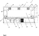
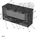
- Figures 3 and 4 illustrate the rear portion of a refrigerator 1 with the back portion of the outer shell removed to expose duct 11.
- Figure 2 further components have been removed, including any rear wall to the duct 11 other than the refrigerator outer shell, in order to clearly illustrate the duct 11.
- Figure 4 differs from figure 3 in that a drip tray 17 has been retained.
- the drip tray 17 runs underneath the evaporator 14 and serves to collect condensate from the evaporator 14.
- a drain (not highlighted in figure 4 ) is provided to drain the condensate from the drip tray 17.
- the refrigerator 1 further comprises one or more air guides 18.
- Figures 3 and 4 illustrate two air guides 18 positioned either side of the evaporator 14, but the invention is not limited to this.
- the evaporator 14 may be positioned to one side of the duct 11 and a larger air guide 18 provided on the other side of the duct 11 (that is, the position of the evaporator 14 may be asymmetrical in the air duct 11).
- Each air guide 18 serves to close off a portion of the duct 11 to prevent air from flowing through that region.
- each air guide 11 In a depth direction (along an axis extending from the front to the rear of the refrigerator 1) each air guide 11 completely fills the volume between front and rear sides of the duct 11 to block air flow.
- Figures 3 and 4 show each air guide 18 as rectangular with rounded corners, but the shape will vary significantly according to the particular desired air flow for a given configuration of duct 11, evaporator 14, fans 12 and slotted grill 13.
- the air guides 18 are generally thin and loop out from a side wall and return to the side wall of the duct 11.
- the air guides may fill the enclosed portion of the duct 11.
- the duct has an inlet and an outlet defining a flow direction therebetween.
- the evaporator is located in the duct between the inlet and the outlet, the evaporator being narrower than the duct in a direction perpendicular to the flow direction and in a plane defined by a surface of the evaporator, and the air guide is located in the duct to one side of the evaporator in the perpendicular direction such that it directs air through the duct over the surface of the evaporator.
- the air guides extend fully to the sides of the duct 11 (in addition to filling the full thickness of the duct 11) thereby preventing air flow from passing outside of the air guides 18.
- this is not an essential feature: it may be that an alternative shape of air guide 18 serves to channel air from fans 12 without extending to the sides of the duct 11.
- an air guide 18 may extend from a top part of the duct 11 to a bottom part of the duct 11 without reaching to the sides. It is not essential that an air guide 18 necessary reaches any side (or top or bottom) of the duct 11.
- an air guide may be relatively small compared to the overall size of the duct 11 and other components and positioned close to a fan 12 (or grill 13 if the air flow in the duct 11 is reversed) in order to guide air flow over the evaporator 14 without partially or completely closing off a portion of the duct 11.
- Each air guide 18 serves to direct air flow from the fans 12 to the slotted grill 13 so as to maximise the air flow over the evaporator 14. Accordingly, as shown in figures 3 and 4 the air guides approach close to the evaporator 14 to substantially prevent air from passing to the left or to the right of the evaporator 14 in the view of figure 3 . In other examples the or each air guide 18 may touch the evaporator 14. This channelling of air flow through the duct 11 over the evaporator 14 increases the efficiency of heat transfer.
- the air guides 18 return to the sides of the duct in their lower part so as to permit air flow to reach the full width of slotted grill 13.
- the air guides 18 may be shaped to direct the air flow to any portion of a slotted grill 13 to provide for optimal return of air into the compartment 2.
- the air guides 18 may approach close to the fans 12 in their upper part to channel air flow over the evaporator 14.
- each air guide 18 is 290 mm tall and 160 mm wide, with a radius of curvature at each corner of 100 mm.
- Each air guide 18 may be formed, for instance, from shaped foam which is glued in position within the duct 11, for instance using self-adhesive tape. The thickness of each air guide 18 is not a critical dimension given that the air guide 18 extends to the side of the duct and so entirely closes off a contained portion of the duct 11.
- FIG. 5 this is a cross sectional view through a refrigerator 1.
- Duct 11 can be seen to be defined between a rear wall 19 of compartment 2 and a rear duct wall 20.
- the evaporator 14 is positioned midway between walls 19 and 20 such that air passes in front of and behind the evaporator 14, as illustrated by the vertical arrows. Air is drawn into the duct by fan 12 as illustrated by the right arrow and expelled back into compartment 2 through slotted grill 13 as illustrated by the left arrows.
- the larger, upper left arrow is indicative of a larger volume of air passing in front of evaporator 14 (to the left in figure 5 ) and a smaller volume of air passing behind evaporator 14 and then under the evaporator 14 to reach slotted grill 13. Air flowing in front of the evaporator 14 may also be higher speed.
- the fan is illustrated as being orientated vertically. However, the fan may be inclined forwards or backwards in order to control the pressure differential across the fan and to direct the flow of air from compartment 2 into duct 11.
- Figure 6 illustrates three different forms of air guide 18.
- (a) is the same form of air guide illustrated in figures 3 and 4 .
- This may be formed from foam, for instance shaped foam with an adhesive tape backing to reduce mounting time during refrigerator construction.
- foam and similar materials may be readily formed in any shape for any desired air flow, with minimal turbulence by avoiding sharp corners.
- (b) and (c) illustrate alternatives formed from shaped channels which may be made from metal or plastic.
- the skilled person will realise that the chosen shape will depend on the particular shape and disposition of duct, fans, grill and evaporator, together with the desired air flow.
- the skilled person will further take account of the specified cooling within the compartment storing products, together with specified air flow volumes between the compartment and the duct.
- an air guide ensures that air within the duct is directed exclusively over the evaporator and then (if required) fans outwards underneath the evaporator to fill the entire width of a slotted grill for returning cooled air to the compartment.
- Each air guide 18 illustrated in figure 6 is vertically symmetrical, though exact symmetry is not essential. Particularly, for an air flow direction such as illustrated in figures 3 to 5 , where air flows downwards through the duct 11, the air guide 18 extends from the side wall of the duct 11 at the upper part closest to the fans 12 in order to direct air flow inwards towards and over the evaporator 14. The air guides 18 then return to the side wall of the duct 11. The lower part of each air guide 18 may not directly channel air flow but serves to reduce turbulence in the duct 11.
- each of the duct 11 and the evaporator 14 may be vertically orientated (that is, taller than they are wide).
- additional slots or holes may be provided for air to return to the product compartment.
- a further slotted grill 13 may be provided partway along the vertical dimension of the duct 11, or even close to the top of the duct 11. Additional air return channels to the product compartment allow for more even product cooling.
- the air duct 11 described herein is described as a vertically orientated thin box, though it will be appreciated that the shape of the duct may vary significantly.
- the evaporator 14 is generally described as a plate. In certain examples the evaporator 14 may comprise generally parallel sheets joined together periodically by welds, though the exact shape of the evaporator 14 falls outside of the scope of the present invention.
Landscapes
- Engineering & Computer Science (AREA)
- Chemical & Material Sciences (AREA)
- Combustion & Propulsion (AREA)
- Physics & Mathematics (AREA)
- Mechanical Engineering (AREA)
- Thermal Sciences (AREA)
- General Engineering & Computer Science (AREA)
- Cold Air Circulating Systems And Constructional Details In Refrigerators (AREA)
Abstract
Description
- The present invention relates to a climatization container, for instance a refrigerator or a freezer.
- A climatization container comprises a container suitable for keeping contents stored therein under particular climatic conditions, for instance within a predetermined temperature or humidity range. Climatization containers are commonly used for storing products such as food and beverages. Particular examples include refrigerators and freezers where the primary requirement is to store food and beverages within a predetermined temperature range. Where in the present document reference is made to a particular example of a climatization container, for instance a refrigerator or freezer, this should be understood to include all types of climatization containers unless the context requires that it is limited to the particular example.
- A climatization container may comprise a compartment defined by walls and closable by a door, one or more drawers or a combination of both. Within the compartment is a shelf support, or series of shelf supports, supporting one or more shelves. On each shelf products, for instance food and beverage products, may be stored.
- A climatization container typically requires air to be distributed around a compartment, and for this a fan is provided to draw air in from one part of the compartment, channel the air through a duct, and expel air to another part of the compartment. The fan intake and outlet may be spaced apart to encourage air flow around the compartment. For the example of a refrigerator or freezer, a cooling system will also be provided to cool the air, and the fan may be provided upstream or downstream of the cooling system. Particularly, the cooling system includes an evaporator within the duct such that air passing through the duct passes over the evaporator to cool the air before being expelled back into the compartment. The shape and disposition of the evaporator within such a duct, and the shape of the duct itself, can have significant impact on the efficiency of the cooling system.
- It is an aim of certain examples of the present invention to increase the efficiency of a cooling system for a climatization container.
- According to the present invention, there is provided a climatization container according to
claim 1. - Advantageously, for a climatization container according to the present invention, the cooling system may be operated more efficiently because the air guide in the duct directs air over the evaporator, rather than permitting air flow to bypass the evaporator. Accordingly a greater proportion of the air passing through the duct is cooled by the evaporator resulting in more efficient cooling and so the cooling system may be operated for a smaller proportion of the time.
- Examples of the invention are further described hereinafter with reference to the accompanying drawings, in which:
-
Figure 1 illustrates a climatization container according to an example of the present invention; -
Figure 2 illustrates a partially exposed rear view of a climatization container with air guides removed; -
Figure 3 illustrates a partially exposed rear view of a climatization container according to an example of the present invention; -
Figure 4 illustrates a partially exposed rear-view perspective view of a climatization container according to an example of the present invention; -
Figure 5 illustrates a cross section view of a climatization container according to an example of the present invention; and -
Figure 6 illustrates alternative forms of air guides according to examples of the present invention. - Referring to
figure 1 , this illustrates arefrigerator 1 according to an example of the present invention. Therefrigerator 1 may be for storing and cooling beverage bottles in a direct sales environment, such as a bar or restaurant. The following description refers to refrigerators as examples of climatization containers according to the present invention. The invention is not limited only to refrigerators. - The
refrigerator 1 includes a product display/cooling compartment. Therefrigerator 1 is defined byside walls top wall 5,rear wall 6 andbottom wall 7. Thecompartment 2 is closable at the front bydoors 8, in this example three doors. Alternatively, the front of thecompartment 2 may be closed off by one or more drawers. Or there may be a combination of drawers and doors allowing access to products 9 within the refrigerator (in this example, beverage bottles). -
Figure 2 illustrates a reverse view of therefrigerator 1 with a back wall removed to illustrate components of a cooling system. The detail of the cooling system may in most respects be entirely conventional and so will not be described in detail. Therefrigerator 1 may be constructed with a double wall surrounding the sides and rear of thecompartment 2. That is, thecompartment 2 may be defined by walls and therefrigerator 1 may have anouter shell 10. Insulation (not illustrated) may be provided between the compartment walls and theouter shell 10 surrounding at least part of thecompartment 2. At the rear of the compartment 2 aduct 11 is provided between the rear wall of the compartment 2 (an inner wall) and the outer shell 10 (or an intervening wall defining the rear of the duct 11). Theduct 11 comprises a vertical channel between the rear wall of thecompartment 2 and the outer shell of the refrigerator 1 (or between the rear wall of thecompartment 2 and an intervening vertical wall). In the example offigure 2 theduct 11 extends substantially the full width of therefrigerator 1 betweenwalls refrigerator 1 from thetop 5. Theduct 11 thus comprises a generally cuboid form that is generally the width of the refrigerator, tall and relatively shallow (as will be apparent from the side view offigure 5 described below). It will be understood that in other examples theduct 11 may be provided upon a side of thecompartment 2 instead of the rear of the compartment. -
Figure 2 further illustrates threefans 12 which extend through the rear wall of thecompartment 2 so that air may be drawn into theduct 11 from thecompartment 2. The number offans 12 will depend on the width of therefrigerator 1 and the required volume of air to be moved. A slottedgrill 13 returns air from the duct into thecompartment 2. Thegrill 13 is an example of a vent or orifice through which air may pass. The particular form of thegrill 13 is not essential to the invention. It will be appreciated that thefans 12 may operate in reverse: they may draw air through theduct 11 and expel the air into thecompartment 2. Furthermore, the positions of thefans 12 and the slottedgrill 13 may be reversed. Positioning theduct 11 behind the product compartment 2 (with fans at the top or bottom) maximises the product display capacity within the compartment relative to positioning the fans and the duct to one side. - The cooling system further comprises an
evaporator 14, which may be referred to as an evaporator plate, and acompressor 15. Briefly, thecompressor 15 compresses a refrigerant which is then circulated through theevaporator 14. Heat is transferred from air passing through theduct 11 to the refrigerant as it evaporates such that the air is cooled before it is expelled into thecompartment 2 through the slottedgrill 13. The compressor 15 (and further unlabelled portions of the cooling system) is located within acooling system compartment 16 below theduct 11. That is, in a vertical direction, theduct 11 is defined between thetop wall 5 of therefrigerator 1 and thecooling compartment 16. Certain components, for instance adrip tray 17, have been removed infigure 2 in order to avoid obscuring features of theduct 11.Drip tray 17 is visible infigures 4 . Generally, thefans 12 are located at the top of theduct 11 distributed across the width of theduct 11, and theslotted grill 13 extends across the full width of the duct 11 (and indeed substantially the full width of the refrigerator 1) such that air drawn through theduct 11 by thefans 12 is expelled towards the bottom ofcompartment 2 across the full width of thecompartment 2. -
Evaporator 14 is illustrated as a substantially flat plate, though the exact form may vary significantly in ways that extend beyond the present invention. Theevaporator 14 may be disposed in the middle of the duct 11 (along an axis extending from the front to the rear of the refrigerator 1) such that air can flow both in front of and behind the evaporator 14 (which is more clearly visible in the cross-section side view offigure 5 ). To enable this flow over both sides of theevaporator 14, theevaporator 14 is spaced from the top of the duct (such that thefans 12 are visible infigure 2 ) and is spaced from the bottom of the duct 11 (such that part of the slottedgrill 13 is visible underneath the evaporator 14). - It is desirable to maximise the heat exchange between air in the
duct 11 and theevaporator 14 by maximising the degree to which the air flow passes over the surfaces of theevaporator 14. This increases the efficiency of theevaporator 14, and hence the overall efficiency of the cooling system (resulting in the cooling system being operated for a smaller proportion of the time and therefrigerator 1 as a whole being more energy efficient). However, a competing requirement with energy efficiency is cost. Therefrigerator 1 offigure 1 is shown as a three-door refrigerator 1. However, it may be desirable to have a range of refrigerators with different configurations of doors and drawers, and hence different overall widths. To reduce costs it is desirable to standard components across the range of refrigerators as far as possible, including standardising components of the cooling system. - One option for standardisation is to use an
evaporator 14 having a standard width regardless of the width of therefrigerator 1. As illustrated infigure 2 , theevaporator 14 is less wide than the overall width of theduct 11 and therefrigerator 1 so that it may also be used in a narrower refrigerator 1 (for instance, one having only two doors).Figure 2 illustrates the situation which would occur, other than for the use of air guides according to the present invention (described and illustrated below in connection withfigures 3 ,4 and6 ). Infigure 2 it is possible for air to pass from the outer pair offans 12 to the outer extremities of the slottedgrill 13 without passing over theevaporator 14. That is, a portion of the air flow generated byouter fans 12 passes to the left and to the right of theevaporator 14 in the view offigure 2 as indicated by the dashed lines. This portion of the air flow may either avoid the evaporator entirely or may only partially pass over the surface of the evaporator and so is not cooled effectively. The efficiency of the cooling system is compromised by the use of anevaporator 14 that is less wide than theduct 11. Furthermore, air returning to thecompartment 2 through the side portions of the slottedgrill 13 may be warmer than air returning through the centre of the slottedgrill 13. This may lead to uneven cooling of products within thecompartment 2. This compromised efficiency is avoided through the present invention. -
Figures 3 and4 illustrate the rear portion of arefrigerator 1 with the back portion of the outer shell removed to exposeduct 11. As forfigure 2 , further components have been removed, including any rear wall to theduct 11 other than the refrigerator outer shell, in order to clearly illustrate theduct 11.Figure 4 differs fromfigure 3 in that adrip tray 17 has been retained. Thedrip tray 17 runs underneath theevaporator 14 and serves to collect condensate from theevaporator 14. A drain (not highlighted infigure 4 ) is provided to drain the condensate from thedrip tray 17. - According to the present invention, the
refrigerator 1 further comprises one or more air guides 18.Figures 3 and4 illustrate two air guides 18 positioned either side of theevaporator 14, but the invention is not limited to this. For instance, theevaporator 14 may be positioned to one side of theduct 11 and alarger air guide 18 provided on the other side of the duct 11 (that is, the position of theevaporator 14 may be asymmetrical in the air duct 11). Eachair guide 18 serves to close off a portion of theduct 11 to prevent air from flowing through that region. In a depth direction (along an axis extending from the front to the rear of the refrigerator 1) eachair guide 11 completely fills the volume between front and rear sides of theduct 11 to block air flow.Figures 3 and4 show eachair guide 18 as rectangular with rounded corners, but the shape will vary significantly according to the particular desired air flow for a given configuration ofduct 11,evaporator 14,fans 12 and slottedgrill 13. In the example offigures 3 and4 the air guides 18 are generally thin and loop out from a side wall and return to the side wall of theduct 11. In alternative examples the air guides may fill the enclosed portion of theduct 11. The duct has an inlet and an outlet defining a flow direction therebetween. The evaporator is located in the duct between the inlet and the outlet, the evaporator being narrower than the duct in a direction perpendicular to the flow direction and in a plane defined by a surface of the evaporator, and the air guide is located in the duct to one side of the evaporator in the perpendicular direction such that it directs air through the duct over the surface of the evaporator. - In the example of
figures 3 and4 the air guides extend fully to the sides of the duct 11 (in addition to filling the full thickness of the duct 11) thereby preventing air flow from passing outside of the air guides 18. However, this is not an essential feature: it may be that an alternative shape ofair guide 18 serves to channel air fromfans 12 without extending to the sides of theduct 11. For instance, anair guide 18 may extend from a top part of theduct 11 to a bottom part of theduct 11 without reaching to the sides. It is not essential that anair guide 18 necessary reaches any side (or top or bottom) of theduct 11. In an alternative example an air guide may be relatively small compared to the overall size of theduct 11 and other components and positioned close to a fan 12 (orgrill 13 if the air flow in theduct 11 is reversed) in order to guide air flow over theevaporator 14 without partially or completely closing off a portion of theduct 11. - Each
air guide 18 serves to direct air flow from thefans 12 to the slottedgrill 13 so as to maximise the air flow over theevaporator 14. Accordingly, as shown infigures 3 and4 the air guides approach close to theevaporator 14 to substantially prevent air from passing to the left or to the right of theevaporator 14 in the view offigure 3 . In other examples the or eachair guide 18 may touch theevaporator 14. This channelling of air flow through theduct 11 over theevaporator 14 increases the efficiency of heat transfer. - In the example of
figures 3 and4 the air guides 18 return to the sides of the duct in their lower part so as to permit air flow to reach the full width of slottedgrill 13. In other examples, the air guides 18 may be shaped to direct the air flow to any portion of a slottedgrill 13 to provide for optimal return of air into thecompartment 2. In other examples the air guides 18 may approach close to thefans 12 in their upper part to channel air flow over theevaporator 14. - In
figure 3 dimensions for anexample refrigerator 1 and certain components are indicated, in millimetres. The illustratedrefrigerator 1 has a horizontal orientation. Similarly theduct 11 andevaporator 14 are horizontally orientated. Theduct 11 is 524 mm tall and 1579 mm wide. Eachair guide 18 is 290 mm tall and 160 mm wide, with a radius of curvature at each corner of 100 mm. Eachair guide 18 may be formed, for instance, from shaped foam which is glued in position within theduct 11, for instance using self-adhesive tape. The thickness of eachair guide 18 is not a critical dimension given that theair guide 18 extends to the side of the duct and so entirely closes off a contained portion of theduct 11. - Turning now to
figure 5 , this is a cross sectional view through arefrigerator 1.Duct 11 can be seen to be defined between arear wall 19 ofcompartment 2 and arear duct wall 20. Theevaporator 14 is positioned midway betweenwalls evaporator 14, as illustrated by the vertical arrows. Air is drawn into the duct byfan 12 as illustrated by the right arrow and expelled back intocompartment 2 through slottedgrill 13 as illustrated by the left arrows. The larger, upper left arrow is indicative of a larger volume of air passing in front of evaporator 14 (to the left infigure 5 ) and a smaller volume of air passing behindevaporator 14 and then under theevaporator 14 to reach slottedgrill 13. Air flowing in front of theevaporator 14 may also be higher speed. - In
figure 5 the fan is illustrated as being orientated vertically. However, the fan may be inclined forwards or backwards in order to control the pressure differential across the fan and to direct the flow of air fromcompartment 2 intoduct 11. -
Figure 6 illustrates three different forms ofair guide 18. (a) is the same form of air guide illustrated infigures 3 and4 . This may be formed from foam, for instance shaped foam with an adhesive tape backing to reduce mounting time during refrigerator construction. Advantageously, foam and similar materials may be readily formed in any shape for any desired air flow, with minimal turbulence by avoiding sharp corners. (b) and (c) illustrate alternatives formed from shaped channels which may be made from metal or plastic. The skilled person will realise that the chosen shape will depend on the particular shape and disposition of duct, fans, grill and evaporator, together with the desired air flow. In designing the required shape of air guide, the skilled person will further take account of the specified cooling within the compartment storing products, together with specified air flow volumes between the compartment and the duct. Preferably, an air guide ensures that air within the duct is directed exclusively over the evaporator and then (if required) fans outwards underneath the evaporator to fill the entire width of a slotted grill for returning cooled air to the compartment. - Each
air guide 18 illustrated infigure 6 is vertically symmetrical, though exact symmetry is not essential. Particularly, for an air flow direction such as illustrated infigures 3 to 5 , where air flows downwards through theduct 11, theair guide 18 extends from the side wall of theduct 11 at the upper part closest to thefans 12 in order to direct air flow inwards towards and over theevaporator 14. The air guides 18 then return to the side wall of theduct 11. The lower part of eachair guide 18 may not directly channel air flow but serves to reduce turbulence in theduct 11. - In a further example the
refrigerator 1, and particularly each of theduct 11 and theevaporator 14 may be vertically orientated (that is, taller than they are wide). In further examples, particularly where a refrigerator is vertically orientated, additional slots or holes may be provided for air to return to the product compartment. For instance, a further slottedgrill 13 may be provided partway along the vertical dimension of theduct 11, or even close to the top of theduct 11. Additional air return channels to the product compartment allow for more even product cooling. - Generally, the
air duct 11 described herein is described as a vertically orientated thin box, though it will be appreciated that the shape of the duct may vary significantly. Similarly, theevaporator 14 is generally described as a plate. In certain examples theevaporator 14 may comprise generally parallel sheets joined together periodically by welds, though the exact shape of theevaporator 14 falls outside of the scope of the present invention. - Throughout this specification, the words "comprise" and "contain" and variations of them mean "including but not limited to", and they are not intended to (and do not) exclude other components, integers or steps. Throughout this specification, the singular encompasses the plural unless the context otherwise requires. In particular, where the indefinite article is used, the specification is to be understood as contemplating plurality as well as singularity, unless the context requires otherwise. Throughout this specification, the term "about" is used to provide flexibility to a range endpoint by providing that a given value may be "a little above" or "a little below" the endpoint. The degree of flexibility of this term can be dictated by the particular variable and can be determined based on experience and the associated description herein.
- Features, integers or characteristics described in conjunction with a particular aspect or example of the invention are to be understood to be applicable to any other aspect or example described herein unless incompatible therewith. All of the features disclosed in this specification, and/or all of the steps of any method or process so disclosed, may be combined in any combination, except combinations where at least some of such features and/or steps are mutually exclusive. The invention is not restricted to the details of any foregoing examples. The invention extends to any novel feature or combination of features disclosed in this specification. It will be also be appreciated that, throughout this specification, language in the general form of "X for Y" (where Y is some action, activity or step and X is some means for carrying out that action, activity or step) encompasses means X adapted or arranged specifically, but not exclusively, to do Y.
- Each feature disclosed in this specification may be replaced by alternative features serving the same, equivalent or similar purpose, unless expressly stated otherwise. Thus, unless expressly stated otherwise, each feature disclosed is one example only of a generic series of equivalent or similar features.
- The reader's attention is directed to all papers and documents which are filed concurrently with or previous to this specification in connection with this application and which are open to public inspection with this specification, and the contents of all such papers and documents are incorporated herein by reference.
Claims (8)
- A climatization container comprising:a compartment for storing products;a duct;a fan configured to draw air from the compartment into the duct;a cooling system including an evaporator located in the duct; andat least one air guide located in the duct;wherein the evaporator is narrower than the duct in a plane defined by a surface of the evaporator, the air guide directing air drawn from the compartment such that it passes over a surface of the evaporator.
- A climatization container according to claim 1, further comprising an outer shell at least partially surrounding the compartment such that the duct is defined between a wall of the compartment and the outer shell.
- A climatization container according to claim 1 or claim 2, wherein the duct is positioned behind a rear side of the compartment opposite to a front side of the compartment which opens with a door or a drawer.
- A climatization container according to any one of the preceding claims, wherein the fan is located in the duct on a first side of the evaporator and a vent between the duct and the compartment is located on a second, opposite side of the evaporator such that air from the compartment flows between the fan and the vent over a surface of the evaporator.
- A climatization container according to claim 4, wherein the air guide closes off a volume of the duct to prevent air flow between the fan and the vent from passing through that volume.
- A climatization container according to claim 4 or claim 5, wherein the air guide is positioned to one side of the evaporator in the direction of air flow between the fan and the vent.
- A climatization container according to claim 6, wherein first and second air guides are provided either side of the evaporator such that substantially all of the air flow between the fan and the vent passes over a surface of the evaporator.
- A climatization container according to any one of the preceding claims, wherein the climatization container comprises a refrigerator or freezer.
Applications Claiming Priority (1)
| Application Number | Priority Date | Filing Date | Title |
|---|---|---|---|
| EP20206795 | 2020-11-10 |
Publications (2)
| Publication Number | Publication Date |
|---|---|
| EP3995764A1 true EP3995764A1 (en) | 2022-05-11 |
| EP3995764B1 EP3995764B1 (en) | 2024-06-05 |
Family
ID=73497504
Family Applications (1)
| Application Number | Title | Priority Date | Filing Date |
|---|---|---|---|
| EP21195057.1A Active EP3995764B1 (en) | 2020-11-10 | 2021-09-06 | Climatization container |
Country Status (1)
| Country | Link |
|---|---|
| EP (1) | EP3995764B1 (en) |
Cited By (1)
| Publication number | Priority date | Publication date | Assignee | Title |
|---|---|---|---|---|
| CN113983741A (en) * | 2021-12-01 | 2022-01-28 | 上海理工大学 | Low-temperature box with high cold capacity utilization rate |
Citations (5)
| Publication number | Priority date | Publication date | Assignee | Title |
|---|---|---|---|---|
| EP0592004A1 (en) * | 1992-10-09 | 1994-04-13 | Daewoo Electronics Co., Ltd | Refrigerator |
| KR20080068350A (en) * | 2007-01-19 | 2008-07-23 | 삼성전자주식회사 | Refrigerator |
| TW200928264A (en) * | 2007-11-28 | 2009-07-01 | Toshiba Kk | Refrigerator |
| WO2016082622A1 (en) * | 2014-11-27 | 2016-06-02 | 青岛海尔股份有限公司 | Refrigerator |
| US20180340726A1 (en) * | 2017-05-26 | 2018-11-29 | Lg Electronics Inc. | Refrigerator |
-
2021
- 2021-09-06 EP EP21195057.1A patent/EP3995764B1/en active Active
Patent Citations (5)
| Publication number | Priority date | Publication date | Assignee | Title |
|---|---|---|---|---|
| EP0592004A1 (en) * | 1992-10-09 | 1994-04-13 | Daewoo Electronics Co., Ltd | Refrigerator |
| KR20080068350A (en) * | 2007-01-19 | 2008-07-23 | 삼성전자주식회사 | Refrigerator |
| TW200928264A (en) * | 2007-11-28 | 2009-07-01 | Toshiba Kk | Refrigerator |
| WO2016082622A1 (en) * | 2014-11-27 | 2016-06-02 | 青岛海尔股份有限公司 | Refrigerator |
| US20180340726A1 (en) * | 2017-05-26 | 2018-11-29 | Lg Electronics Inc. | Refrigerator |
Cited By (1)
| Publication number | Priority date | Publication date | Assignee | Title |
|---|---|---|---|---|
| CN113983741A (en) * | 2021-12-01 | 2022-01-28 | 上海理工大学 | Low-temperature box with high cold capacity utilization rate |
Also Published As
| Publication number | Publication date |
|---|---|
| EP3995764B1 (en) | 2024-06-05 |
Similar Documents
| Publication | Publication Date | Title |
|---|---|---|
| CN209893727U (en) | Refrigerator with side ventilation holes in the side walls of the compressor compartment | |
| CN1954182A (en) | Modular Cooling Box with Condensate Evaporation Tray | |
| US6422031B1 (en) | Refrigeration appliance with impingement cooling system | |
| US20160128492A1 (en) | Refrigerated display appliances | |
| US20160025402A1 (en) | Supercooling refrigerator | |
| EP3926263B1 (en) | Refrigerator having return air inlets formed in two side walls of refrigerator body | |
| EP3699532B1 (en) | Entrance refrigerator | |
| EP3929513B1 (en) | Refrigerator with air blower located upstream of lateral side of evaporator | |
| CN110375486B (en) | Refrigerator and heat dissipation control method thereof | |
| EP3995764B1 (en) | Climatization container | |
| CN209893744U (en) | Large-capacity refrigerator | |
| US20110259896A1 (en) | Refrigeration unit having an air channel | |
| CN110375476B (en) | A refrigerator with the cooling chamber located at the lower inside of the freezer | |
| JP2001108347A (en) | refrigerator | |
| EP3916321B1 (en) | A climatization container | |
| EP4006458B1 (en) | Refrigerator with obliquely arranged evaporator | |
| EP3926266B1 (en) | Refrigerator having blower transversely disposed besides and downstream of evaporator | |
| WO2022042073A1 (en) | Display freezer | |
| JPH11325695A (en) | Indirect cooling refrigerator | |
| CN111609609B (en) | Refrigerator using cross-flow fan for heat dissipation | |
| KR20230009079A (en) | Storehouse | |
| RU2299383C2 (en) | Refrigerator | |
| KR20230009082A (en) | Storehouse | |
| JP2021162206A (en) | Showcase | |
| JP2021099171A (en) | refrigerator |
Legal Events
| Date | Code | Title | Description |
|---|---|---|---|
| PUAI | Public reference made under article 153(3) epc to a published international application that has entered the european phase |
Free format text: ORIGINAL CODE: 0009012 |
|
| STAA | Information on the status of an ep patent application or granted ep patent |
Free format text: STATUS: THE APPLICATION HAS BEEN PUBLISHED |
|
| AK | Designated contracting states |
Kind code of ref document: A1 Designated state(s): AL AT BE BG CH CY CZ DE DK EE ES FI FR GB GR HR HU IE IS IT LI LT LU LV MC MK MT NL NO PL PT RO RS SE SI SK SM TR |
|
| STAA | Information on the status of an ep patent application or granted ep patent |
Free format text: STATUS: REQUEST FOR EXAMINATION WAS MADE |
|
| 17P | Request for examination filed |
Effective date: 20221111 |
|
| RBV | Designated contracting states (corrected) |
Designated state(s): AL AT BE BG CH CY CZ DE DK EE ES FI FR GB GR HR HU IE IS IT LI LT LU LV MC MK MT NL NO PL PT RO RS SE SI SK SM TR |
|
| GRAP | Despatch of communication of intention to grant a patent |
Free format text: ORIGINAL CODE: EPIDOSNIGR1 |
|
| STAA | Information on the status of an ep patent application or granted ep patent |
Free format text: STATUS: GRANT OF PATENT IS INTENDED |
|
| INTG | Intention to grant announced |
Effective date: 20240126 |
|
| P01 | Opt-out of the competence of the unified patent court (upc) registered |
Effective date: 20240213 |
|
| GRAS | Grant fee paid |
Free format text: ORIGINAL CODE: EPIDOSNIGR3 |
|
| GRAA | (expected) grant |
Free format text: ORIGINAL CODE: 0009210 |
|
| STAA | Information on the status of an ep patent application or granted ep patent |
Free format text: STATUS: THE PATENT HAS BEEN GRANTED |
|
| AK | Designated contracting states |
Kind code of ref document: B1 Designated state(s): AL AT BE BG CH CY CZ DE DK EE ES FI FR GB GR HR HU IE IS IT LI LT LU LV MC MK MT NL NO PL PT RO RS SE SI SK SM TR |
|
| REG | Reference to a national code |
Ref country code: CH Ref legal event code: EP |
|
| REG | Reference to a national code |
Ref country code: DE Ref legal event code: R096 Ref document number: 602021014021 Country of ref document: DE |
|
| REG | Reference to a national code |
Ref country code: IE Ref legal event code: FG4D |
|
| REG | Reference to a national code |
Ref country code: NL Ref legal event code: FP |
|
| REG | Reference to a national code |
Ref country code: LT Ref legal event code: MG9D |
|
| PG25 | Lapsed in a contracting state [announced via postgrant information from national office to epo] |
Ref country code: BG Free format text: LAPSE BECAUSE OF FAILURE TO SUBMIT A TRANSLATION OF THE DESCRIPTION OR TO PAY THE FEE WITHIN THE PRESCRIBED TIME-LIMIT Effective date: 20240605 |
|
| PG25 | Lapsed in a contracting state [announced via postgrant information from national office to epo] |
Ref country code: FI Free format text: LAPSE BECAUSE OF FAILURE TO SUBMIT A TRANSLATION OF THE DESCRIPTION OR TO PAY THE FEE WITHIN THE PRESCRIBED TIME-LIMIT Effective date: 20240605 Ref country code: HR Free format text: LAPSE BECAUSE OF FAILURE TO SUBMIT A TRANSLATION OF THE DESCRIPTION OR TO PAY THE FEE WITHIN THE PRESCRIBED TIME-LIMIT Effective date: 20240605 |
|
| PG25 | Lapsed in a contracting state [announced via postgrant information from national office to epo] |
Ref country code: GR Free format text: LAPSE BECAUSE OF FAILURE TO SUBMIT A TRANSLATION OF THE DESCRIPTION OR TO PAY THE FEE WITHIN THE PRESCRIBED TIME-LIMIT Effective date: 20240906 |
|
| PG25 | Lapsed in a contracting state [announced via postgrant information from national office to epo] |
Ref country code: ES Free format text: LAPSE BECAUSE OF FAILURE TO SUBMIT A TRANSLATION OF THE DESCRIPTION OR TO PAY THE FEE WITHIN THE PRESCRIBED TIME-LIMIT Effective date: 20240605 |
|
| PG25 | Lapsed in a contracting state [announced via postgrant information from national office to epo] |
Ref country code: LV Free format text: LAPSE BECAUSE OF FAILURE TO SUBMIT A TRANSLATION OF THE DESCRIPTION OR TO PAY THE FEE WITHIN THE PRESCRIBED TIME-LIMIT Effective date: 20240605 |
|
| PG25 | Lapsed in a contracting state [announced via postgrant information from national office to epo] |
Ref country code: NO Free format text: LAPSE BECAUSE OF FAILURE TO SUBMIT A TRANSLATION OF THE DESCRIPTION OR TO PAY THE FEE WITHIN THE PRESCRIBED TIME-LIMIT Effective date: 20240905 Ref country code: LV Free format text: LAPSE BECAUSE OF FAILURE TO SUBMIT A TRANSLATION OF THE DESCRIPTION OR TO PAY THE FEE WITHIN THE PRESCRIBED TIME-LIMIT Effective date: 20240605 Ref country code: HR Free format text: LAPSE BECAUSE OF FAILURE TO SUBMIT A TRANSLATION OF THE DESCRIPTION OR TO PAY THE FEE WITHIN THE PRESCRIBED TIME-LIMIT Effective date: 20240605 Ref country code: GR Free format text: LAPSE BECAUSE OF FAILURE TO SUBMIT A TRANSLATION OF THE DESCRIPTION OR TO PAY THE FEE WITHIN THE PRESCRIBED TIME-LIMIT Effective date: 20240906 Ref country code: FI Free format text: LAPSE BECAUSE OF FAILURE TO SUBMIT A TRANSLATION OF THE DESCRIPTION OR TO PAY THE FEE WITHIN THE PRESCRIBED TIME-LIMIT Effective date: 20240605 Ref country code: ES Free format text: LAPSE BECAUSE OF FAILURE TO SUBMIT A TRANSLATION OF THE DESCRIPTION OR TO PAY THE FEE WITHIN THE PRESCRIBED TIME-LIMIT Effective date: 20240605 Ref country code: BG Free format text: LAPSE BECAUSE OF FAILURE TO SUBMIT A TRANSLATION OF THE DESCRIPTION OR TO PAY THE FEE WITHIN THE PRESCRIBED TIME-LIMIT Effective date: 20240605 Ref country code: RS Free format text: LAPSE BECAUSE OF FAILURE TO SUBMIT A TRANSLATION OF THE DESCRIPTION OR TO PAY THE FEE WITHIN THE PRESCRIBED TIME-LIMIT Effective date: 20240905 |
|
| REG | Reference to a national code |
Ref country code: AT Ref legal event code: MK05 Ref document number: 1692726 Country of ref document: AT Kind code of ref document: T Effective date: 20240605 |
|
| PG25 | Lapsed in a contracting state [announced via postgrant information from national office to epo] |
Ref country code: PT Free format text: LAPSE BECAUSE OF FAILURE TO SUBMIT A TRANSLATION OF THE DESCRIPTION OR TO PAY THE FEE WITHIN THE PRESCRIBED TIME-LIMIT Effective date: 20241007 |
|
| PG25 | Lapsed in a contracting state [announced via postgrant information from national office to epo] |
Ref country code: PT Free format text: LAPSE BECAUSE OF FAILURE TO SUBMIT A TRANSLATION OF THE DESCRIPTION OR TO PAY THE FEE WITHIN THE PRESCRIBED TIME-LIMIT Effective date: 20241007 |
|
| PG25 | Lapsed in a contracting state [announced via postgrant information from national office to epo] |
Ref country code: PL Free format text: LAPSE BECAUSE OF FAILURE TO SUBMIT A TRANSLATION OF THE DESCRIPTION OR TO PAY THE FEE WITHIN THE PRESCRIBED TIME-LIMIT Effective date: 20240605 |
|
| PG25 | Lapsed in a contracting state [announced via postgrant information from national office to epo] |
Ref country code: EE Free format text: LAPSE BECAUSE OF FAILURE TO SUBMIT A TRANSLATION OF THE DESCRIPTION OR TO PAY THE FEE WITHIN THE PRESCRIBED TIME-LIMIT Effective date: 20240605 |
|
| PG25 | Lapsed in a contracting state [announced via postgrant information from national office to epo] |
Ref country code: AT Free format text: LAPSE BECAUSE OF FAILURE TO SUBMIT A TRANSLATION OF THE DESCRIPTION OR TO PAY THE FEE WITHIN THE PRESCRIBED TIME-LIMIT Effective date: 20240605 Ref country code: IS Free format text: LAPSE BECAUSE OF FAILURE TO SUBMIT A TRANSLATION OF THE DESCRIPTION OR TO PAY THE FEE WITHIN THE PRESCRIBED TIME-LIMIT Effective date: 20241005 |
|
| PG25 | Lapsed in a contracting state [announced via postgrant information from national office to epo] |
Ref country code: CZ Free format text: LAPSE BECAUSE OF FAILURE TO SUBMIT A TRANSLATION OF THE DESCRIPTION OR TO PAY THE FEE WITHIN THE PRESCRIBED TIME-LIMIT Effective date: 20240605 |
|
| PG25 | Lapsed in a contracting state [announced via postgrant information from national office to epo] |
Ref country code: RO Free format text: LAPSE BECAUSE OF FAILURE TO SUBMIT A TRANSLATION OF THE DESCRIPTION OR TO PAY THE FEE WITHIN THE PRESCRIBED TIME-LIMIT Effective date: 20240605 Ref country code: SK Free format text: LAPSE BECAUSE OF FAILURE TO SUBMIT A TRANSLATION OF THE DESCRIPTION OR TO PAY THE FEE WITHIN THE PRESCRIBED TIME-LIMIT Effective date: 20240605 |
|
| PG25 | Lapsed in a contracting state [announced via postgrant information from national office to epo] |
Ref country code: SM Free format text: LAPSE BECAUSE OF FAILURE TO SUBMIT A TRANSLATION OF THE DESCRIPTION OR TO PAY THE FEE WITHIN THE PRESCRIBED TIME-LIMIT Effective date: 20240605 |
|
| PG25 | Lapsed in a contracting state [announced via postgrant information from national office to epo] |
Ref country code: SM Free format text: LAPSE BECAUSE OF FAILURE TO SUBMIT A TRANSLATION OF THE DESCRIPTION OR TO PAY THE FEE WITHIN THE PRESCRIBED TIME-LIMIT Effective date: 20240605 Ref country code: SK Free format text: LAPSE BECAUSE OF FAILURE TO SUBMIT A TRANSLATION OF THE DESCRIPTION OR TO PAY THE FEE WITHIN THE PRESCRIBED TIME-LIMIT Effective date: 20240605 Ref country code: RO Free format text: LAPSE BECAUSE OF FAILURE TO SUBMIT A TRANSLATION OF THE DESCRIPTION OR TO PAY THE FEE WITHIN THE PRESCRIBED TIME-LIMIT Effective date: 20240605 Ref country code: PL Free format text: LAPSE BECAUSE OF FAILURE TO SUBMIT A TRANSLATION OF THE DESCRIPTION OR TO PAY THE FEE WITHIN THE PRESCRIBED TIME-LIMIT Effective date: 20240605 Ref country code: IS Free format text: LAPSE BECAUSE OF FAILURE TO SUBMIT A TRANSLATION OF THE DESCRIPTION OR TO PAY THE FEE WITHIN THE PRESCRIBED TIME-LIMIT Effective date: 20241005 Ref country code: EE Free format text: LAPSE BECAUSE OF FAILURE TO SUBMIT A TRANSLATION OF THE DESCRIPTION OR TO PAY THE FEE WITHIN THE PRESCRIBED TIME-LIMIT Effective date: 20240605 Ref country code: CZ Free format text: LAPSE BECAUSE OF FAILURE TO SUBMIT A TRANSLATION OF THE DESCRIPTION OR TO PAY THE FEE WITHIN THE PRESCRIBED TIME-LIMIT Effective date: 20240605 Ref country code: AT Free format text: LAPSE BECAUSE OF FAILURE TO SUBMIT A TRANSLATION OF THE DESCRIPTION OR TO PAY THE FEE WITHIN THE PRESCRIBED TIME-LIMIT Effective date: 20240605 |
|
| PG25 | Lapsed in a contracting state [announced via postgrant information from national office to epo] |
Ref country code: IT Free format text: LAPSE BECAUSE OF FAILURE TO SUBMIT A TRANSLATION OF THE DESCRIPTION OR TO PAY THE FEE WITHIN THE PRESCRIBED TIME-LIMIT Effective date: 20240605 |
|
| REG | Reference to a national code |
Ref country code: DE Ref legal event code: R097 Ref document number: 602021014021 Country of ref document: DE |
|
| REG | Reference to a national code |
Ref country code: DE Ref legal event code: R119 Ref document number: 602021014021 Country of ref document: DE |
|
| PLBE | No opposition filed within time limit |
Free format text: ORIGINAL CODE: 0009261 |
|
| STAA | Information on the status of an ep patent application or granted ep patent |
Free format text: STATUS: NO OPPOSITION FILED WITHIN TIME LIMIT |
|
| PG25 | Lapsed in a contracting state [announced via postgrant information from national office to epo] |
Ref country code: DK Free format text: LAPSE BECAUSE OF FAILURE TO SUBMIT A TRANSLATION OF THE DESCRIPTION OR TO PAY THE FEE WITHIN THE PRESCRIBED TIME-LIMIT Effective date: 20240605 |
|
| PG25 | Lapsed in a contracting state [announced via postgrant information from national office to epo] |
Ref country code: MC Free format text: LAPSE BECAUSE OF FAILURE TO SUBMIT A TRANSLATION OF THE DESCRIPTION OR TO PAY THE FEE WITHIN THE PRESCRIBED TIME-LIMIT Effective date: 20240605 |
|
| REG | Reference to a national code |
Ref country code: CH Ref legal event code: PL |
|
| 26N | No opposition filed |
Effective date: 20250306 |
|
| PG25 | Lapsed in a contracting state [announced via postgrant information from national office to epo] |
Ref country code: LU Free format text: LAPSE BECAUSE OF NON-PAYMENT OF DUE FEES Effective date: 20240906 |
|
| PG25 | Lapsed in a contracting state [announced via postgrant information from national office to epo] |
Ref country code: DE Free format text: LAPSE BECAUSE OF NON-PAYMENT OF DUE FEES Effective date: 20250401 |
|
| PG25 | Lapsed in a contracting state [announced via postgrant information from national office to epo] |
Ref country code: CH Free format text: LAPSE BECAUSE OF NON-PAYMENT OF DUE FEES Effective date: 20240930 |
|
| PG25 | Lapsed in a contracting state [announced via postgrant information from national office to epo] |
Ref country code: IE Free format text: LAPSE BECAUSE OF NON-PAYMENT OF DUE FEES Effective date: 20240906 |
|
| PG25 | Lapsed in a contracting state [announced via postgrant information from national office to epo] |
Ref country code: SE Free format text: LAPSE BECAUSE OF FAILURE TO SUBMIT A TRANSLATION OF THE DESCRIPTION OR TO PAY THE FEE WITHIN THE PRESCRIBED TIME-LIMIT Effective date: 20240605 |
|
| PGFP | Annual fee paid to national office [announced via postgrant information from national office to epo] |
Ref country code: NL Payment date: 20250926 Year of fee payment: 5 |
|
| PGFP | Annual fee paid to national office [announced via postgrant information from national office to epo] |
Ref country code: BE Payment date: 20250929 Year of fee payment: 5 Ref country code: GB Payment date: 20250929 Year of fee payment: 5 |
|
| PGFP | Annual fee paid to national office [announced via postgrant information from national office to epo] |
Ref country code: FR Payment date: 20250925 Year of fee payment: 5 |
|
| PG25 | Lapsed in a contracting state [announced via postgrant information from national office to epo] |
Ref country code: CY Free format text: LAPSE BECAUSE OF FAILURE TO SUBMIT A TRANSLATION OF THE DESCRIPTION OR TO PAY THE FEE WITHIN THE PRESCRIBED TIME-LIMIT; INVALID AB INITIO Effective date: 20210906 |
|
| PG25 | Lapsed in a contracting state [announced via postgrant information from national office to epo] |
Ref country code: HU Free format text: LAPSE BECAUSE OF FAILURE TO SUBMIT A TRANSLATION OF THE DESCRIPTION OR TO PAY THE FEE WITHIN THE PRESCRIBED TIME-LIMIT; INVALID AB INITIO Effective date: 20210906 |