EP3995762A1 - A receiver drier bottle assembly - Google Patents
A receiver drier bottle assembly Download PDFInfo
- Publication number
- EP3995762A1 EP3995762A1 EP20461580.1A EP20461580A EP3995762A1 EP 3995762 A1 EP3995762 A1 EP 3995762A1 EP 20461580 A EP20461580 A EP 20461580A EP 3995762 A1 EP3995762 A1 EP 3995762A1
- Authority
- EP
- European Patent Office
- Prior art keywords
- plug
- screw
- receiver drier
- cover
- opening
- Prior art date
- Legal status (The legal status is an assumption and is not a legal conclusion. Google has not performed a legal analysis and makes no representation as to the accuracy of the status listed.)
- Granted
Links
Images


Classifications
-
- F—MECHANICAL ENGINEERING; LIGHTING; HEATING; WEAPONS; BLASTING
- F25—REFRIGERATION OR COOLING; COMBINED HEATING AND REFRIGERATION SYSTEMS; HEAT PUMP SYSTEMS; MANUFACTURE OR STORAGE OF ICE; LIQUEFACTION SOLIDIFICATION OF GASES
- F25B—REFRIGERATION MACHINES, PLANTS OR SYSTEMS; COMBINED HEATING AND REFRIGERATION SYSTEMS; HEAT PUMP SYSTEMS
- F25B43/00—Arrangements for separating or purifying gases or liquids; Arrangements for vaporising the residuum of liquid refrigerant, e.g. by heat
- F25B43/003—Filters
-
- F—MECHANICAL ENGINEERING; LIGHTING; HEATING; WEAPONS; BLASTING
- F25—REFRIGERATION OR COOLING; COMBINED HEATING AND REFRIGERATION SYSTEMS; HEAT PUMP SYSTEMS; MANUFACTURE OR STORAGE OF ICE; LIQUEFACTION SOLIDIFICATION OF GASES
- F25B—REFRIGERATION MACHINES, PLANTS OR SYSTEMS; COMBINED HEATING AND REFRIGERATION SYSTEMS; HEAT PUMP SYSTEMS
- F25B2339/00—Details of evaporators; Details of condensers
- F25B2339/04—Details of condensers
- F25B2339/044—Condensers with an integrated receiver
- F25B2339/0441—Condensers with an integrated receiver containing a drier or a filter
-
- F—MECHANICAL ENGINEERING; LIGHTING; HEATING; WEAPONS; BLASTING
- F25—REFRIGERATION OR COOLING; COMBINED HEATING AND REFRIGERATION SYSTEMS; HEAT PUMP SYSTEMS; MANUFACTURE OR STORAGE OF ICE; LIQUEFACTION SOLIDIFICATION OF GASES
- F25B—REFRIGERATION MACHINES, PLANTS OR SYSTEMS; COMBINED HEATING AND REFRIGERATION SYSTEMS; HEAT PUMP SYSTEMS
- F25B2400/00—Component parts or details not otherwise provided for in this subclass
- F25B2400/16—Receivers
- F25B2400/162—Receivers characterised by the plug or stop
-
- F—MECHANICAL ENGINEERING; LIGHTING; HEATING; WEAPONS; BLASTING
- F25—REFRIGERATION OR COOLING; COMBINED HEATING AND REFRIGERATION SYSTEMS; HEAT PUMP SYSTEMS; MANUFACTURE OR STORAGE OF ICE; LIQUEFACTION SOLIDIFICATION OF GASES
- F25B—REFRIGERATION MACHINES, PLANTS OR SYSTEMS; COMBINED HEATING AND REFRIGERATION SYSTEMS; HEAT PUMP SYSTEMS
- F25B2500/00—Problems to be solved
- F25B2500/01—Geometry problems, e.g. for reducing size
Definitions
- the present invention relates to a receiver drier bottle assembly for a condenser, in particular for a vehicle Heating Ventilation and Air-Conditioning system.
- connecting block 3 substantial portion of the connecting block 3, i.e. the flange portion 3b is disposed outside the cover 2 and occupies substantial area of the cover 2. Accordingly, there is limited space on the cover 2 for mounting of other elements on the cover 2. Further, flange portion 3b mounted on the cover 2 intrudes into operating space of adjacent elements mounted on the cover 2, thereby resulting in packaging issues. Further, such configuration of the connecting block 3 increases overall mass of connecting pipe-cover assembly of the receiver drier bottle assembly 1 and involves notable machining, thereby increasing the overall cost. Further, such configuration involves aligning the cover and the connecting block that cause inconvenience in assembly.
- the connecting pipe "p" is comparatively far from a screw axis of the bolt 4, thereby resulting in mechanical failures due to the connecting pipe "p” exerting comparatively higher torque on the connecting block 3.
- two separate holes one bore 2b and one counter bore 2c are required to be formed on the cover 2, thereby causing stress concentrations and weakening of the cover 2.
- a receiver drier bottle assembly that obviates the problems faced by the conventional receiver drier bottle assembly.
- a connecting block forming connecting pipe-cover assembly addresses the mechanical failure issues by reducing torque exerted by a connecting pipe on the connecting block.
- a receiver drier bottle assembly that is comparatively inexpensive as a connecting block forming connecting pipe-cover assembly involves comparatively less material and less machining compared to the conventional connecting block.
- a connecting block mounted on a cover of a receiver drier bottle is of compact configuration, thereby enabling mounting of additional elements on the cover.
- a receiver drier bottle assembly that is simple in construction and convenient to assemble.
- the plug remains above the external surface of the receiver drier bottle cover when inserted in the plug opening.
- a base of the plug cutout and a bottom of the screw supported on the base are flat surfaces.
- the present invention relates to a receiver drier bottle assembly for a condenser of a vehicle Heating Ventilation and Air-conditioning system, wherein the receiver drier bottle assembly includes a plug opening formed on a receiver drier bottle cover, a plug received in the plug opening, a screw opening formed on a receiver drier bottle cover and a screw.
- the plug is formed with a plug cutout that has first threads.
- the screw opening partially overlapping the plug opening and complementary to the plug cutout include second threads.
- the screw with external threads formed thereon is disposed partially on the plug cutout to engage with the first threads and partially on the screw opening to engage with the second threads.
- the cover 20 includes other holes formed thereon to enable mounting of other elements on the cover 20. Considering limited space on the cover 20, all the elements mounted thereon are required to be of compact configuration to enable mounting of other elements without interfering with the adjacent elements.
- the plug opening 10 extends to a first counter bore 12 formed on the cover 20.
- the first counter bore 12 formed on the cover 20 includes a larger diameter 12a and a smaller diameter 12b.
- the screw opening 40 is partially overlapping the plug opening 10.
- the screw opening 40 extends to a screw-receiving bore 42 that is complementary to the plug cutout 32.
- the screw-receiving bore 42 includes second threads 42a formed on sidewalls thereof.
- the second threads 42a formed on sidewalls of the screw-receiving bore 42 are complementary to the first threads 32a formed on sidewalls of the plug cutout 32.
- the screw-receiving bore 42 is defined between sidewalls of the plug cutout 32 the complementary sidewalls of the screw opening 40.
- the screw opening 40 is provided with a chamfer along periphery thereof to facilitate removal of the screw 50 from the screw opening 40.
Landscapes
- Engineering & Computer Science (AREA)
- Chemical & Material Sciences (AREA)
- Analytical Chemistry (AREA)
- Power Engineering (AREA)
- Physics & Mathematics (AREA)
- Mechanical Engineering (AREA)
- Thermal Sciences (AREA)
- General Engineering & Computer Science (AREA)
- Closures For Containers (AREA)
Abstract
Description
- The present invention relates to a receiver drier bottle assembly for a condenser, in particular for a vehicle Heating Ventilation and Air-Conditioning system.
- Conventional air conditioning system, for example, air conditioning system for a vehicle cabin includes a condenser, an evaporator, an expansion device, a compressor and a heater. Generally, the conventional air conditioning system configured with an expansion valve is also configured with a receiver drier that is disposed in a high-pressure section of the air conditioning system/ air conditioning loop. The receiver drier is usually located between a condenser and the expansion valve in the air conditioning loop. Generally, the condenser is configured with the receiver drier along an outlet side of the condenser, particularly, along a length of an outlet collector of a pair of collectors of the condenser. The receiver drier includes a tubular casing in the form of an airtight container referred to as receiver drier bottle with an inlet and an outlet. The inlet receives liquid refrigerant along with some uncondensed refrigerant, debris and incompressible moisture, if any, from a first pass defining a condensing section of the condenser via a first portion of the outlet collector. The outlet delivers the liquid refrigerant from which incompressible moisture and debris are removed, to a second pass defining the subcooling section of the condenser via a second section of the outlet collector, or to the rest of the refrigerant circuit.
- As shown in
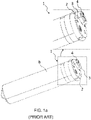
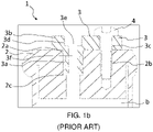
Figs. 1a and1b , a condenser may be connected to the inlet and the outlet of the receiver drier via connecting pipes that configure fluid communication between the receiver drier and the outlet side of the condenser. Generally, a receiverdrier bottle assembly 1 includes acover 2 closing an end of the receiver drier bottle "b" and a connectingblock 3 mounted on thecover 2. The connectingblock 3 is mounted on thecover 2 using a bolt orscrew 4. The connectingblock 3 forms a connection and a fluid communication between the connecting pipe and the interior of the receiver drier bottle "b". The connectingblock 3 includes a plug portion 3a and aflange portion 3b for configuring connection between the connectingblock 3 and thecover 2. The plug portion 3a is plugged into acounter bore 2c extending from a plug opening 2a formed on thecover 2 and theflange portion 3b rests over thecover 2. In particular, a substantial portion of the connectingblock 3 is disposed outside the receiver driver bottle "b". - The
flange portion 3b includes a bolt-receivinghole 3c and a counter bore 3d. The bolt-receivinghole 3c is aligned with a correspondingcomplementary bore 2b formed on thecover 2 and thebolt 4 passes through the bolt-receivinghole 3c and thebore 2b aligned to each other to mount theflange portion 3b to thecover 2. The counter bore 3d forms connection and fluid communication between the connecting pipe "p" and an interior of the receiver drier bottle "b". Particularly, alarge diameter bore 3e of the counter bore 3d receives the connecting pipe "p" while a small diameter bore 3f of the counter bore 3d extends through the plug portion 3a and is in fluid communication with the interior of the receiver drier bottle "b". However, with such configuration of the connectingblock 3, substantial portion of the connectingblock 3, i.e. theflange portion 3b is disposed outside thecover 2 and occupies substantial area of thecover 2. Accordingly, there is limited space on thecover 2 for mounting of other elements on thecover 2. Further,flange portion 3b mounted on thecover 2 intrudes into operating space of adjacent elements mounted on thecover 2, thereby resulting in packaging issues. Further, such configuration of the connectingblock 3 increases overall mass of connecting pipe-cover assembly of the receiverdrier bottle assembly 1 and involves notable machining, thereby increasing the overall cost. Further, such configuration involves aligning the cover and the connecting block that cause inconvenience in assembly. Also, with such configuration of the connecting pipe-cover assembly of the receiver drier bottle assembly, the connecting pipe "p" is comparatively far from a screw axis of thebolt 4, thereby resulting in mechanical failures due to the connecting pipe "p" exerting comparatively higher torque on the connectingblock 3. Further, for mounting the connectingblock 3 on the cover two separate holes, onebore 2b and onecounter bore 2c are required to be formed on thecover 2, thereby causing stress concentrations and weakening of thecover 2. - Accordingly, there is a need for a receiver drier bottle assembly that obviates the problems faced by the conventional receiver drier bottle assembly. Particularly, there is a need for a receiver drier bottle assembly, wherein a connecting block forming connecting pipe-cover assembly addresses the mechanical failure issues by reducing torque exerted by a connecting pipe on the connecting block. Further, there is a need for a receiver drier bottle assembly that is comparatively inexpensive as a connecting block forming connecting pipe-cover assembly involves comparatively less material and less machining compared to the conventional connecting block. Furthermore, there is a need for a receiver drier bottle assembly, wherein a connecting block mounted on a cover of a receiver drier bottle is of compact configuration, thereby enabling mounting of additional elements on the cover. Further, there is a need for a receiver drier bottle assembly that is simple in construction and convenient to assemble.
- An object of the present invention is to provide a receiver drier bottle assembly that obviates the problems faced by the conventional receiver drier bottle assembly.
- Another object of the present invention is to provide a receiver drier bottle assembly, wherein a connecting block forming connecting pipe-cover assembly addresses the mechanical failure issues by reducing torque exerted by a connecting pipe on the connecting block
- Yet another object of the present invention is to provide a receiver drier bottle assembly that is comparatively inexpensive as a connecting block forming connecting pipe-cover assembly involves comparatively less material and less machining compared to the conventional connecting block
- Still another object of the present invention is to provide a receiver drier bottle assembly, wherein a connecting block mounted on a cover of a receiver drier bottle is of compact configuration, thereby enabling mounting of additional elements on the cover.
- Further object of the the present invention is to provide a receiver drier bottle assembly, wherein a connecting block mounted on a cover of a receiver drier bottle is of compact configuration and accordingly does not interfere with operation of other adjacent elements mounted on the cover.
- In the present description, some elements or parameters may be indexed, such as a first element and a second element. In this case, unless stated otherwise, this indexation is only meant to differentiate and name elements which are similar but not identical. No idea of priority should be inferred from such indexation, as these terms may be switched without betraying the invention. Additionally, this indexation does not imply any order in mounting or use of the elements of the invention.
- A receiver drier bottle assembly, hereinafter referred to as "assembly" is disclosed in accordance with an embodiment of the present disclosure. The receiver drier bottle assembly includes a plug opening and a screw opening formed on a cover and a plug and a screw received in the plug opening and the screw opening. The plug is formed with a plug cutout that has first threads. The screw opening is partially overlapping the plug opening and extends to a screw-receiving bore. The screw-receiving bore is complementary to the plug cutout and is formed with second threads. The screw with external threads formed thereon is disposed partially on the plug cutout to engage with the first threads and partially on the screw-receiving bore to engage with the second threads. Accordingly, the screw immobilizes the plug when the screw is inserted in the screw-receiving bore through the screw opening.
- Preferably, the plug flushes with an external surface of the receiver drier bottle cover when inserted in the plug opening.
- Alternatively, at least a portion of the plug remains above the external surface of the receiver drier bottle cover when inserted in the plug opening.
- Otherwise, the plug is below the external surface of the receiver drier bottle cover when inserted in the plug opening.
- Typically, the plug includes a head portion and a tube portion formed by impact extrusion.
- In accordance with an embodiment, a base of the plug cutout and a bottom of the screw supported on the base are flat surfaces.
- Alternatively, the bottom of the screw is conical and is supported on the base of the plug cutout that is complementary to the conical bottom of the screw.
- Preferably, the bottom of the screw is hemi-spherical and is supported on the base of the plug cutout complementary to the hemi-spherical bottom of the screw.
- Generally, the receiver drier bottle assembly includes a plurality of screws inserted in a plurality of the screw-receiving bores through respective screw openings disposed along periphery of the plug opening to immobilize different sides of the plug.
- Other characteristics, details and advantages of the invention can be inferred from the description of the invention hereunder. A more complete appreciation of the invention and many of the attendant advantages thereof will be readily obtained as the same becomes better understood by reference to the following detailed description when considered in connection with the accompanying figures, wherein:
-
FIG. 1a illustrates an isometric view of a conventional receiver drier assembly, also is depicted an enlarged view of a cover- connecting block assembly thereof; -
FIG. 1b illustrates a section view of the conventional receiver drier assembly ofFIG. 1a depicting the internal details thereof; -
FIG. 2a illustrates an isometric view of a receiver drier assembly of the present invention in accordance with an embodiment of the present invention, also is depicted an enlarged view of a cover- plug assembly thereof; -
FIG. 2b illustrates a sectional view of the receiver drier assembly ofFIG. 2a depicting the internal details thereof; and -
FIG. 2c illustrates another isometric sectional view of the receiver drier assembly ofFIG. 2a . - The present invention relates to a receiver drier bottle assembly for a condenser of a vehicle Heating Ventilation and Air-conditioning system, wherein the receiver drier bottle assembly includes a plug opening formed on a receiver drier bottle cover, a plug received in the plug opening, a screw opening formed on a receiver drier bottle cover and a screw. The plug is formed with a plug cutout that has first threads. The screw opening partially overlapping the plug opening and complementary to the plug cutout include second threads. The screw with external threads formed thereon is disposed partially on the plug cutout to engage with the first threads and partially on the screw opening to engage with the second threads. Accordingly, the screw immobilizes the plug with respect to the receiver drier bottle when the screw is inserted in the screw opening. However, the present invention is not limited to receiver drier bottle assembly and is also applicable in any vehicular and non-vehicular applications, wherein a connecting block form connection and fluid communication between elements disposed on different sides of a cover for either element, without protruding out and without occupying much space of the cover.
- A conventional receiver
drier bottle assembly 1 includes a cover - connecting pipe assembly, wherein the cover - connecting pipe assembly includes a connectingblock 3 mounted on acover 2 of a receiver drier bottle "b". The connectingblock 3 includes a plug portion 3a and aflange portion 3b. The plug portion 3a is received in thecover 2. Theflange portion 3b is disposed outside thecover 2 and is mounted on thecover 2 by means of thebolt 4. Theflange portion 3b occupies substantial area of thecover 2. Accordingly, there is limited space on thecover 2 for mounting of other elements on thecover 2. Further, theflange portion 3b of the connectingblock 3 mounted on thecover 2 intrudes into operating space of adjacent elements mounted on thecover 2, thereby resulting in packaging issues. Further, such configuration of the connectingblock 3 increases overall mass of connecting pipe-cover assembly of the receiverdrier bottle assembly 1 and involves notable machining, thereby increasing the cost. Further, such configuration involves aligning the cover and the connecting block that cause inconvenience in assembly. Also, with such configuration of the connecting pipe-cover assembly of the receiver drier bottle assembly, the connecting pipe "p" is comparatively far from a screw axis of thebolt 4, thereby resulting in mechanical failures due to the connecting pipe "p" exerting comparatively higher torque on the connectingblock 3. Further, for mounting the connectingblock 3 on the cover two separate holes, onebore 2b and one counter bore 2c are required to be formed on thecover 2, thereby causing stress concentrations and weakening of thecover 2. - The present invention envisages a receiver drier bottle assembly that obviates the problems faced by the conventional receiver drier bottle assembly. The receiver drier bottle assembly of the present invention includes a plug received inside a cover of a receiver drier instead of a connecting block mounted on the cover and accordingly is of a compact configuration. Particularly, the connecting block flushes with an external surface of the receiver drier bottle cover when inserted in the plug opening. Accordingly allows mounting of other elements on the cover and does not interfere with operation of other adjacent elements mounted on the cover.
- A receiver drier bottle includes a tubular casing with extreme ends thereof closed by respective covers to define an enclosure. The receiver drier includes a filter element and a desiccant material disposed inside the enclosure. The filter element traps debris that may have entered the air conditioning loop, whereas the desiccant material traps moisture carried with the condensate received from the condenser and prevents the moisture from reaching and harming other critical elements such as for example compressor disposed downstream of the condenser and receiver drier in the air conditioning loop.
-
FIG. 2a illustrates an isometric view of a receiverdrier bottle assembly 100, hereinafter referred to asassembly 100 in accordance with an embodiment of the present invention.FIG. 2b illustrates a sectional view of theassembly 100 depicting the internal details thereof.FIG. 2c illustrates another isometric sectional view of the receiver drier assembly. Theassembly 100 includes aplug opening 10 formed on a receiverdrier bottle cover 20, hereinafter simply referred to as acover 20, aplug 30, ascrew opening 40 again formed on thecover 20 and ascrew 50. - The
cover 20 is either integrally formed to the tubular casing of the receiver drier or is threadably engaged to the extreme ends of the tubular casing of the receiver drier. Both inlet pipe for ingress of condensed refrigerant into the receiver drier bottle and the outlet pipe for egress of the condensed refrigerant out of the receiver drier bottle are connected to thecover 20. Theplug opening 10 is formed on thecover 20. Thescrew opening 40 is also formed on thecover 20. Thescrew opening 40 is at least partially overlapping theplug opening 10. Apart from the plug opening 10 for configuring connection of the inlet pipe or the outlet pipe to thecover 20 and thescrew opening 40 for mounting theplug 30 to thecover 20, other elements are also mounted on thecover 20. Particularly, thecover 20 includes other holes formed thereon to enable mounting of other elements on thecover 20. Considering limited space on thecover 20, all the elements mounted thereon are required to be of compact configuration to enable mounting of other elements without interfering with the adjacent elements. Theplug opening 10 extends to a first counter bore 12 formed on thecover 20. The first counter bore 12 formed on thecover 20 includes alarger diameter 12a and asmaller diameter 12b. - The
plug 30 is received in the first counter bore 12 through theplug opening 10. Preferably, top of theplug 30 flushes with an external surface of thecover 20 when theplug 30 is inserted into the first counter bore 12 through theplug opening 10. Theplug opening 10 includes a chamfer along the periphery thereof. Further, theplug 30 includes a chamfer along periphery of the plug head to facilitate removal of theplug 30 from theplug opening 10. Alternatively, at least a portion of theplug 30 remains above the external surface of thecover 20 when theplug 30 is inserted in the counter bore 12 through theplug opening 10. More specifically, theplug 30 slightly extends above the external surface of thecover 20 when theplug 30 is inserted in the first counter bore 12 through theplug opening 10. In yet another embodiment of the present invention, theplug 30 is below the external surface of thecover 20 when theplug 30 is inserted in first counter bore 12 through theplug opening 10. Theplug 30 includes ahead portion 30a and atube portion 30b formed by impact extrusion. Thetube portion 30b includes external grooves that receive sealing elements, particularly O-rings to configure leak-proof engagement between theplug 30 and the first counter bore 12. Thetube portion 30b of theplug 30 forms connection with thesmaller diameter 12b of the first counter bore 12. More specifically, theplug 30 includes a second counter bore 36. The second counter bore 36 forms connection and fluid communication between the connecting pipe "P" and an interior of the receiver drier bottle "B". The second counter bore 36 includes alarge diameter bore 36a and a small diameter throughbore 36b. Particularly, thelarge diameter bore 36a formed on thehead portion 30a of the second counter bore 36 receives the connecting pipe "P", whereas thesmall diameter bore 36b of the second counter bore 36 extends to and is in fluid communication with the interior of the receiver drier bottle "B". Theplug 30 is formed with aplug cutout 32 that hasfirst threads 32a formed on sidewalls of theplug cutout 32. - The
screw opening 40 is partially overlapping theplug opening 10. Thescrew opening 40 extends to a screw-receivingbore 42 that is complementary to theplug cutout 32. The screw-receivingbore 42 includessecond threads 42a formed on sidewalls thereof. Thesecond threads 42a formed on sidewalls of the screw-receivingbore 42 are complementary to thefirst threads 32a formed on sidewalls of theplug cutout 32. The screw-receivingbore 42 is defined between sidewalls of theplug cutout 32 the complementary sidewalls of thescrew opening 40. Thescrew opening 40 is provided with a chamfer along periphery thereof to facilitate removal of thescrew 50 from thescrew opening 40. - The
screw 50 engages with the first and thesecond threads plug cutout 32 and the screw-receivingbore 42 respectively to immobilize theplug 30 with respect to thecover 20. Top of thescrew 50 flushes with an external surface of thecover 20, when thescrew 50 is received inside the screw-receivingbore 42 through thescrew opening 40. Thescrew 50 engages with the first and thesecond threads plug cutout 32 and the screw-receivingbore 42 respectively to define deployed configuration of thescrew 50. The screw head is flat and do not protrude outside thecover 20, when thescrew 50 is in the deployed configuration. The screw head is provided with chamfer along periphery of the screw head to facilitate removal of thescrew 50 from thescrew opening 40. Generally, thescrew 50 is a grub screw that is deployed and un-deployed using an Allen key that interacts with a corresponding hole. However, the present invention is not limited to any particular configuration of the screw and way of deployment and un-deployment of thescrew 50 until thescrew 50 remains inside the screw-receivingbore 42 formed on thecover 20 in the deployed configuration of thescrew 50. Thescrew 50 with external threads 52 formed thereon is disposed partially on theplug cutout 32 to engage with thefirst threads 32a and partially on the screw-receivingbore 42 to engage with thesecond threads 42a. Accordingly, thescrew 50 immobilizes theplug 30 with respect to thecover 20, when thescrew 50 is inserted in the screw-receivingbore 42 through thescrew opening 40. Instead of a single screw for mounting or immobilizing theplug 30 with respect to thecover 20, a plurality ofscrews 50 can be inserted in the screw-receivingbore 42 through therespective screw openings 40 disposed along periphery of the plug opening 10 to immobilize different sides of theplug 30. However, instead of thescrew 50 engaging with the first and thesecond threads plug cutout 32 and the screw-receivingbore 42 respectively to immobilize theplug 30 with respect to thecover 20, another engagement element engaging with the sidewalls of theplug cutout 32 and the screw-receivingbore 42 can be used to immobilize theplug 30 with respect to thecover 20. More specifically, the present invention is not limited to any particular configuration of the engagement element, number and placement of the engagement element engaging with the sidewalls of theplug cutout 32 and the screw-receivingbore 42 to immobilize theplug 30 with respect to thecover 20. - The
screw opening 40 is overlapping theplug opening 10. The screw opening extends to the screw-receivingbore 42, wherein the screw-receivingbore 42 is at least partially overlapping the first counter bore 12. Accordingly, the connecting pipe "P" received in thelarge diameter bore 36a of theplug 30 received in theplug opening 10 is proximal to mounting axis of thescrew 50 received in the screw-receivingbore 42 through thescrew opening 40 to mount theplug 30 to thecover 20. As such the Moment of force, specifically, the distorting torque acting on theplug 30 or thecover 20 is reduced. Accordingly, the mechanical failure issues arising due to torque exerted by the connecting pipe "P" on theplug 30 is reduced or prevented. Also with such configuration of theassembly 100, the stress concentration on thecover 20 is comparatively reduced compared to cover of the conventional assembly, wherein two separate holes are required to mount the connecting block to the cover. Also, with such configuration, theplug 30 and thescrew 50 for mounting theplug 30 onto thecover 20 are disposed close to each other, thereby occupying comparatively lesser space of thecover 20 compared to conventional assembly. Accordingly, space is available for mounting additional elements on thecover 20 according to customer environment. Further, as the plug of the present invention is compact with respect to the conventional connecting block assembly, mass reduction and cost reducing is achieved. Also, the plug require comparatively less machining and is easier to machine compared to conventional connecting block, thereby further reducing the overall cost. Further, the plug of the present invention require a comparatively smaller screw for mounting the plug to the cover, thereby reducing the screw cost. - Generally, a bottom 50a of the
screw 50 rests partially on a base 32b of the plug cut out 32 and partially on a base 42b of the screw-receivingbore 42. The base 32b of theplug cutout 32 and the bottom 50a of thescrew 50 supported on the base 32b of the plug cut out 32 are flat surfaces. More specifically, the bottom 50a of thescrew 50 rests on a complementary flat surface formed by the base 32b of theplug cutout 32 and the base 42b of thebore 42. Alternatively, the bottom 50a of thescrew 50 is conical and is supported on the base 32b of theplug cutout 32 complementary to theconical bottom 50a of thescrew 50. More specifically, the bottom 50a of thescrew 50 rests on a complementary conical surface formed by the base 32b of theplug cutout 32 and the base 42b of thebore 42 disposed adjacent to each other. Preferably, the bottom 50a of thescrew 50 is hemi-spherical and is supported on the base 32b of theplug cutout 32 complementary to the hemi-spherical bottom 50a of thescrew 50. More specifically, the bottom 50a of thescrew 50 rests on a complementary hemispherical surface formed by the base 32b of theplug cutout 32 and the base 42b of thebore 42 disposed adjacent to each other. With such configuration, extra material is available to reinforce the connection between the base 32b of theplug cutout 32 and sidewalls of thecutout 32, thereby increasing axial load bearing capacity of the base 32b of theplug cutout 32 due to axial load acting on thebase 32b. Accordingly, the chances of mechanical failure of theplug 30 is reduced and service life thereof is increased. - Several modifications and improvement might be applied by the person skilled in the art to the receiver drier bottle assembly as disclosed above and such modifications and improvements will still be considered within the scope and ambit of the present invention, as long as the receiver drier bottle assembly includes a plug opening, a plug, a screw opening and a screw. The plug is received in the plug opening. The plug is formed with a plug cutout that has first threads. The screw opening partially overlaps the plug opening and is complementary to the plug cutout. The screw opening has second threads. The screw with external threads formed thereon is disposed partially on the plug cutout to engage with the first threads and partially on the screw opening to engage with the second threads. Accordingly, the screw immobilizes the plug when the screw is inserted in the screw opening.
- In any case, the invention cannot and should not be limited to the embodiments specifically described in this document, as other embodiments might exist. The invention shall spread to any equivalent means and any technically operating combination of means.
Claims (10)
- A receiver drier bottle assembly (100) comprising:• a plug opening (10) formed on a receiver drier bottle cover (20);• a plug (30) adapted to be received in the plug opening (10), the plug (30) being formed with a plug cutout (32) that has first threads (32a);• a screw opening (40) partially overlapping the plug opening (10) and extending to a screw-receiving bore (42), the screw-receiving bore (42) being complementary to the plug cutout (32) and being formed with second threads (42a); and• a screw (50) with external threads (52) formed thereon which is disposed partially on the plug cutout (32) to engage with the first threads (32a) and partially on the screw-receiving bore (42) to engage with the second threads (42a), the screw (50) immobilizing the plug (30) when the screw (50) is inserted in the screw-receiving bore (42) through the screw opening (40).
- The receiver drier bottle assembly (100) as claimed in the previous claim, wherein the plug (30) flushes with an external surface of the receiver drier bottle cover (20) when inserted in the plug opening (10).
- The receiver drier bottle assembly (100) as claimed in any of the preceding claims, wherein at least a portion of the plug (30) remains above the external surface of the receiver drier bottle cover (20) when inserted in the plug opening (10).
- The receiver drier bottle assembly (100) as claimed in any of the preceding claims, wherein the plug (30) is below the external surface of the receiver drier bottle cover (20) when inserted in the plug opening (10).
- The receiver drier bottle assembly (100) as claimed in any of the preceding claims, wherein the plug (30) comprises a head portion (30a) and a tube portion (30b) formed by impact extrusion.
- The receiver drier bottle assembly (100) as claimed in any of the preceding claims, wherein a base (32b) of the plug cutout (32) and a bottom (50a) of the screw (50) supported on the base (32b) are flat surfaces.
- The receiver drier bottle assembly (100) as claimed in claim 6, wherein the bottom (50a) of the screw (50) is conical and is supported on the base (32b) of the plug cutout (32) complementary to the conical bottom (50a) of the screw (50).
- The receiver drier bottle assembly (100) as claimed in claim 6, the bottom (50a) of the screw (50) is hemi-spherical and is supported on the base (32b) of the plug cutout (32) complementary to the hemi-spherical bottom (50a) of the screw (50).
- The receiver drier bottle assembly (100) as claimed in in any of the preceding claims comprising a plurality of screws (50) inserted in a plurality of the screw-receiving bores (42) through respective screw openings (40) disposed along periphery of the plug opening (10) to immobilize different sides of the plug (30).
- A condenser assembly comprising the receiver drier bottle assembly according to any preceding claim.
Priority Applications (4)
| Application Number | Priority Date | Filing Date | Title |
|---|---|---|---|
| EP20461580.1A EP3995762B1 (en) | 2020-11-06 | 2020-11-06 | A receiver drier bottle assembly |
| US18/035,613 US12498152B2 (en) | 2020-11-06 | 2021-10-21 | Receiver drier bottle assembly |
| CN202180079814.7A CN116685483B (en) | 2020-11-06 | 2021-10-21 | A liquid storage dryer bottle assembly |
| PCT/EP2021/079224 WO2022096279A1 (en) | 2020-11-06 | 2021-10-21 | A receiver drier bottle assembly |
Applications Claiming Priority (1)
| Application Number | Priority Date | Filing Date | Title |
|---|---|---|---|
| EP20461580.1A EP3995762B1 (en) | 2020-11-06 | 2020-11-06 | A receiver drier bottle assembly |
Publications (2)
| Publication Number | Publication Date |
|---|---|
| EP3995762A1 true EP3995762A1 (en) | 2022-05-11 |
| EP3995762B1 EP3995762B1 (en) | 2025-01-15 |
Family
ID=73198252
Family Applications (1)
| Application Number | Title | Priority Date | Filing Date |
|---|---|---|---|
| EP20461580.1A Active EP3995762B1 (en) | 2020-11-06 | 2020-11-06 | A receiver drier bottle assembly |
Country Status (4)
| Country | Link |
|---|---|
| US (1) | US12498152B2 (en) |
| EP (1) | EP3995762B1 (en) |
| CN (1) | CN116685483B (en) |
| WO (1) | WO2022096279A1 (en) |
Citations (3)
| Publication number | Priority date | Publication date | Assignee | Title |
|---|---|---|---|---|
| JPH11223422A (en) * | 1990-09-12 | 1999-08-17 | Zexel:Kk | Receiver tank |
| US20030121278A1 (en) * | 2001-12-28 | 2003-07-03 | Calsonic Kansei Corporation | Receiver-drier for use in an air conditioning system |
| EP2982892A1 (en) * | 2014-08-04 | 2016-02-10 | DL RADIATORS S.p.A. | Eccentric element, locking ring and system |
Family Cites Families (5)
| Publication number | Priority date | Publication date | Assignee | Title |
|---|---|---|---|---|
| US3785164A (en) * | 1972-05-17 | 1974-01-15 | Virginia Chemicals Inc | Precharged receiver drier for automobile air conditioning systems |
| US5427609A (en) * | 1993-09-14 | 1995-06-27 | Horton Industries, Inc. | Device for cleaning and drying compressed gas |
| US5870901A (en) * | 1996-07-18 | 1999-02-16 | James S. Kontos | Air conditioner reactor |
| KR200232853Y1 (en) * | 1999-06-18 | 2001-09-29 | 황한규 | Receiver tank in a body dryer of cooling cycle |
| KR100684259B1 (en) * | 2006-03-28 | 2007-02-16 | 나은수 | Continuous screw dryer prevents internal stratification of the building |
-
2020
- 2020-11-06 EP EP20461580.1A patent/EP3995762B1/en active Active
-
2021
- 2021-10-21 CN CN202180079814.7A patent/CN116685483B/en active Active
- 2021-10-21 WO PCT/EP2021/079224 patent/WO2022096279A1/en not_active Ceased
- 2021-10-21 US US18/035,613 patent/US12498152B2/en active Active
Patent Citations (3)
| Publication number | Priority date | Publication date | Assignee | Title |
|---|---|---|---|---|
| JPH11223422A (en) * | 1990-09-12 | 1999-08-17 | Zexel:Kk | Receiver tank |
| US20030121278A1 (en) * | 2001-12-28 | 2003-07-03 | Calsonic Kansei Corporation | Receiver-drier for use in an air conditioning system |
| EP2982892A1 (en) * | 2014-08-04 | 2016-02-10 | DL RADIATORS S.p.A. | Eccentric element, locking ring and system |
Also Published As
| Publication number | Publication date |
|---|---|
| CN116685483B (en) | 2026-03-27 |
| EP3995762B1 (en) | 2025-01-15 |
| US20240011682A1 (en) | 2024-01-11 |
| US12498152B2 (en) | 2025-12-16 |
| CN116685483A (en) | 2023-09-01 |
| WO2022096279A1 (en) | 2022-05-12 |
Similar Documents
| Publication | Publication Date | Title |
|---|---|---|
| US6349562B1 (en) | Closure for an air conditioner collection vessel | |
| US6189333B1 (en) | Refrigerant filter for use in an automotive air conditioning system | |
| US12498152B2 (en) | Receiver drier bottle assembly | |
| US7691163B2 (en) | Vehicle air dryer | |
| EP3855101B1 (en) | A heat exchanger with horizontally positioned receiver drier | |
| JP4075023B2 (en) | Receiver | |
| JP7670796B2 (en) | Oil Separator | |
| EP3816541B1 (en) | A receiver drier | |
| JPH09217967A (en) | Connecting device for condenser and liquid tank | |
| CN114576891B (en) | Drying filter | |
| KR20010059259A (en) | Check valve and muffler in one | |
| US12539738B2 (en) | Component module for a heat pump system of a vehicle | |
| EP3978837B1 (en) | A receiver drier housing | |
| EP3982061A1 (en) | A heat exchanger assembly | |
| EP4194733A1 (en) | A connection system | |
| KR100925113B1 (en) | Condenser for car air conditioners | |
| KR200250173Y1 (en) | Air conditioning unit for vehicle | |
| KR20000000305U (en) | Compressor Assembly | |
| WO2005115777A1 (en) | Structure for fixing piping to expansion valve | |
| KR200142891Y1 (en) | Compressor | |
| KR100471993B1 (en) | vehicles's for receiver drier in air conditioner | |
| JPH09303906A (en) | Coupling device between header of condenser and liquid tank | |
| EP3982062A1 (en) | A filter assembly for a heat exchanger | |
| KR200228836Y1 (en) | Installation structure of expansion valve for air conditioner | |
| KR20000001187U (en) | Compressor Assembly |
Legal Events
| Date | Code | Title | Description |
|---|---|---|---|
| PUAI | Public reference made under article 153(3) epc to a published international application that has entered the european phase |
Free format text: ORIGINAL CODE: 0009012 |
|
| STAA | Information on the status of an ep patent application or granted ep patent |
Free format text: STATUS: THE APPLICATION HAS BEEN PUBLISHED |
|
| AK | Designated contracting states |
Kind code of ref document: A1 Designated state(s): AL AT BE BG CH CY CZ DE DK EE ES FI FR GB GR HR HU IE IS IT LI LT LU LV MC MK MT NL NO PL PT RO RS SE SI SK SM TR |
|
| STAA | Information on the status of an ep patent application or granted ep patent |
Free format text: STATUS: REQUEST FOR EXAMINATION WAS MADE |
|
| 17P | Request for examination filed |
Effective date: 20221110 |
|
| RBV | Designated contracting states (corrected) |
Designated state(s): AL AT BE BG CH CY CZ DE DK EE ES FI FR GB GR HR HU IE IS IT LI LT LU LV MC MK MT NL NO PL PT RO RS SE SI SK SM TR |
|
| P01 | Opt-out of the competence of the unified patent court (upc) registered |
Effective date: 20230528 |
|
| GRAP | Despatch of communication of intention to grant a patent |
Free format text: ORIGINAL CODE: EPIDOSNIGR1 |
|
| STAA | Information on the status of an ep patent application or granted ep patent |
Free format text: STATUS: GRANT OF PATENT IS INTENDED |
|
| INTG | Intention to grant announced |
Effective date: 20240910 |
|
| RAP3 | Party data changed (applicant data changed or rights of an application transferred) |
Owner name: VALEO AUTOSYSTEMY SP. Z O.O. |
|
| GRAS | Grant fee paid |
Free format text: ORIGINAL CODE: EPIDOSNIGR3 |
|
| GRAA | (expected) grant |
Free format text: ORIGINAL CODE: 0009210 |
|
| STAA | Information on the status of an ep patent application or granted ep patent |
Free format text: STATUS: THE PATENT HAS BEEN GRANTED |
|
| AK | Designated contracting states |
Kind code of ref document: B1 Designated state(s): AL AT BE BG CH CY CZ DE DK EE ES FI FR GB GR HR HU IE IS IT LI LT LU LV MC MK MT NL NO PL PT RO RS SE SI SK SM TR |
|
| REG | Reference to a national code |
Ref country code: CH Ref legal event code: EP Ref country code: GB Ref legal event code: FG4D |
|
| REG | Reference to a national code |
Ref country code: DE Ref legal event code: R096 Ref document number: 602020044750 Country of ref document: DE |
|
| REG | Reference to a national code |
Ref country code: IE Ref legal event code: FG4D |
|
| REG | Reference to a national code |
Ref country code: NL Ref legal event code: MP Effective date: 20250115 |
|
| PG25 | Lapsed in a contracting state [announced via postgrant information from national office to epo] |
Ref country code: NL Free format text: LAPSE BECAUSE OF FAILURE TO SUBMIT A TRANSLATION OF THE DESCRIPTION OR TO PAY THE FEE WITHIN THE PRESCRIBED TIME-LIMIT Effective date: 20250115 |
|
| PG25 | Lapsed in a contracting state [announced via postgrant information from national office to epo] |
Ref country code: RS Free format text: LAPSE BECAUSE OF FAILURE TO SUBMIT A TRANSLATION OF THE DESCRIPTION OR TO PAY THE FEE WITHIN THE PRESCRIBED TIME-LIMIT Effective date: 20250415 |
|
| PG25 | Lapsed in a contracting state [announced via postgrant information from national office to epo] |
Ref country code: FI Free format text: LAPSE BECAUSE OF FAILURE TO SUBMIT A TRANSLATION OF THE DESCRIPTION OR TO PAY THE FEE WITHIN THE PRESCRIBED TIME-LIMIT Effective date: 20250115 |
|
| PG25 | Lapsed in a contracting state [announced via postgrant information from national office to epo] |
Ref country code: PL Free format text: LAPSE BECAUSE OF FAILURE TO SUBMIT A TRANSLATION OF THE DESCRIPTION OR TO PAY THE FEE WITHIN THE PRESCRIBED TIME-LIMIT Effective date: 20250115 |
|
| PG25 | Lapsed in a contracting state [announced via postgrant information from national office to epo] |
Ref country code: ES Free format text: LAPSE BECAUSE OF FAILURE TO SUBMIT A TRANSLATION OF THE DESCRIPTION OR TO PAY THE FEE WITHIN THE PRESCRIBED TIME-LIMIT Effective date: 20250115 |
|
| REG | Reference to a national code |
Ref country code: LT Ref legal event code: MG9D |
|
| PG25 | Lapsed in a contracting state [announced via postgrant information from national office to epo] |
Ref country code: NO Free format text: LAPSE BECAUSE OF FAILURE TO SUBMIT A TRANSLATION OF THE DESCRIPTION OR TO PAY THE FEE WITHIN THE PRESCRIBED TIME-LIMIT Effective date: 20250415 Ref country code: IS Free format text: LAPSE BECAUSE OF FAILURE TO SUBMIT A TRANSLATION OF THE DESCRIPTION OR TO PAY THE FEE WITHIN THE PRESCRIBED TIME-LIMIT Effective date: 20250515 |
|
| REG | Reference to a national code |
Ref country code: AT Ref legal event code: MK05 Ref document number: 1760081 Country of ref document: AT Kind code of ref document: T Effective date: 20250115 |
|
| PG25 | Lapsed in a contracting state [announced via postgrant information from national office to epo] |
Ref country code: HR Free format text: LAPSE BECAUSE OF FAILURE TO SUBMIT A TRANSLATION OF THE DESCRIPTION OR TO PAY THE FEE WITHIN THE PRESCRIBED TIME-LIMIT Effective date: 20250115 |
|
| PG25 | Lapsed in a contracting state [announced via postgrant information from national office to epo] |
Ref country code: LV Free format text: LAPSE BECAUSE OF FAILURE TO SUBMIT A TRANSLATION OF THE DESCRIPTION OR TO PAY THE FEE WITHIN THE PRESCRIBED TIME-LIMIT Effective date: 20250115 Ref country code: PT Free format text: LAPSE BECAUSE OF FAILURE TO SUBMIT A TRANSLATION OF THE DESCRIPTION OR TO PAY THE FEE WITHIN THE PRESCRIBED TIME-LIMIT Effective date: 20250515 |
|
| PG25 | Lapsed in a contracting state [announced via postgrant information from national office to epo] |
Ref country code: BG Free format text: LAPSE BECAUSE OF FAILURE TO SUBMIT A TRANSLATION OF THE DESCRIPTION OR TO PAY THE FEE WITHIN THE PRESCRIBED TIME-LIMIT Effective date: 20250115 Ref country code: GR Free format text: LAPSE BECAUSE OF FAILURE TO SUBMIT A TRANSLATION OF THE DESCRIPTION OR TO PAY THE FEE WITHIN THE PRESCRIBED TIME-LIMIT Effective date: 20250416 |
|
| PG25 | Lapsed in a contracting state [announced via postgrant information from national office to epo] |
Ref country code: AT Free format text: LAPSE BECAUSE OF FAILURE TO SUBMIT A TRANSLATION OF THE DESCRIPTION OR TO PAY THE FEE WITHIN THE PRESCRIBED TIME-LIMIT Effective date: 20250115 |
|
| PG25 | Lapsed in a contracting state [announced via postgrant information from national office to epo] |
Ref country code: SE Free format text: LAPSE BECAUSE OF FAILURE TO SUBMIT A TRANSLATION OF THE DESCRIPTION OR TO PAY THE FEE WITHIN THE PRESCRIBED TIME-LIMIT Effective date: 20250115 |
|
| PG25 | Lapsed in a contracting state [announced via postgrant information from national office to epo] |
Ref country code: SM Free format text: LAPSE BECAUSE OF FAILURE TO SUBMIT A TRANSLATION OF THE DESCRIPTION OR TO PAY THE FEE WITHIN THE PRESCRIBED TIME-LIMIT Effective date: 20250115 |
|
| PG25 | Lapsed in a contracting state [announced via postgrant information from national office to epo] |
Ref country code: DK Free format text: LAPSE BECAUSE OF FAILURE TO SUBMIT A TRANSLATION OF THE DESCRIPTION OR TO PAY THE FEE WITHIN THE PRESCRIBED TIME-LIMIT Effective date: 20250115 |
|
| PG25 | Lapsed in a contracting state [announced via postgrant information from national office to epo] |
Ref country code: IT Free format text: LAPSE BECAUSE OF FAILURE TO SUBMIT A TRANSLATION OF THE DESCRIPTION OR TO PAY THE FEE WITHIN THE PRESCRIBED TIME-LIMIT Effective date: 20250115 |
|
| REG | Reference to a national code |
Ref country code: DE Ref legal event code: R097 Ref document number: 602020044750 Country of ref document: DE |
|
| PG25 | Lapsed in a contracting state [announced via postgrant information from national office to epo] |
Ref country code: CZ Free format text: LAPSE BECAUSE OF FAILURE TO SUBMIT A TRANSLATION OF THE DESCRIPTION OR TO PAY THE FEE WITHIN THE PRESCRIBED TIME-LIMIT Effective date: 20250115 Ref country code: EE Free format text: LAPSE BECAUSE OF FAILURE TO SUBMIT A TRANSLATION OF THE DESCRIPTION OR TO PAY THE FEE WITHIN THE PRESCRIBED TIME-LIMIT Effective date: 20250115 |
|
| PG25 | Lapsed in a contracting state [announced via postgrant information from national office to epo] |
Ref country code: RO Free format text: LAPSE BECAUSE OF FAILURE TO SUBMIT A TRANSLATION OF THE DESCRIPTION OR TO PAY THE FEE WITHIN THE PRESCRIBED TIME-LIMIT Effective date: 20250115 |
|
| PG25 | Lapsed in a contracting state [announced via postgrant information from national office to epo] |
Ref country code: SK Free format text: LAPSE BECAUSE OF FAILURE TO SUBMIT A TRANSLATION OF THE DESCRIPTION OR TO PAY THE FEE WITHIN THE PRESCRIBED TIME-LIMIT Effective date: 20250115 |
|
| PLBE | No opposition filed within time limit |
Free format text: ORIGINAL CODE: 0009261 |
|
| STAA | Information on the status of an ep patent application or granted ep patent |
Free format text: STATUS: NO OPPOSITION FILED WITHIN TIME LIMIT |
|
| 26N | No opposition filed |
Effective date: 20251016 |
|
| PGFP | Annual fee paid to national office [announced via postgrant information from national office to epo] |
Ref country code: DE Payment date: 20251117 Year of fee payment: 6 |
|
| PGFP | Annual fee paid to national office [announced via postgrant information from national office to epo] |
Ref country code: FR Payment date: 20251128 Year of fee payment: 6 |