EP3995745A1 - Gasket for food cooking ovens - Google Patents
Gasket for food cooking ovens Download PDFInfo
- Publication number
- EP3995745A1 EP3995745A1 EP21205170.0A EP21205170A EP3995745A1 EP 3995745 A1 EP3995745 A1 EP 3995745A1 EP 21205170 A EP21205170 A EP 21205170A EP 3995745 A1 EP3995745 A1 EP 3995745A1
- Authority
- EP
- European Patent Office
- Prior art keywords
- gasket
- gutter
- appendage
- crosspiece
- gasket according
- Prior art date
- Legal status (The legal status is an assumption and is not a legal conclusion. Google has not performed a legal analysis and makes no representation as to the accuracy of the status listed.)
- Granted
Links
Images


Classifications
-
- F—MECHANICAL ENGINEERING; LIGHTING; HEATING; WEAPONS; BLASTING
- F16—ENGINEERING ELEMENTS AND UNITS; GENERAL MEASURES FOR PRODUCING AND MAINTAINING EFFECTIVE FUNCTIONING OF MACHINES OR INSTALLATIONS; THERMAL INSULATION IN GENERAL
- F16J—PISTONS; CYLINDERS; SEALINGS
- F16J15/00—Sealings
- F16J15/02—Sealings between relatively-stationary surfaces
- F16J15/021—Sealings between relatively-stationary surfaces with elastic packing
- F16J15/022—Sealings between relatively-stationary surfaces with elastic packing characterised by structure or material
- F16J15/024—Sealings between relatively-stationary surfaces with elastic packing characterised by structure or material the packing being locally weakened in order to increase elasticity
- F16J15/027—Sealings between relatively-stationary surfaces with elastic packing characterised by structure or material the packing being locally weakened in order to increase elasticity and with a hollow profile
-
- F—MECHANICAL ENGINEERING; LIGHTING; HEATING; WEAPONS; BLASTING
- F16—ENGINEERING ELEMENTS AND UNITS; GENERAL MEASURES FOR PRODUCING AND MAINTAINING EFFECTIVE FUNCTIONING OF MACHINES OR INSTALLATIONS; THERMAL INSULATION IN GENERAL
- F16J—PISTONS; CYLINDERS; SEALINGS
- F16J15/00—Sealings
- F16J15/02—Sealings between relatively-stationary surfaces
- F16J15/021—Sealings between relatively-stationary surfaces with elastic packing
- F16J15/022—Sealings between relatively-stationary surfaces with elastic packing characterised by structure or material
- F16J15/024—Sealings between relatively-stationary surfaces with elastic packing characterised by structure or material the packing being locally weakened in order to increase elasticity
- F16J15/025—Sealings between relatively-stationary surfaces with elastic packing characterised by structure or material the packing being locally weakened in order to increase elasticity and with at least one flexible lip
-
- F—MECHANICAL ENGINEERING; LIGHTING; HEATING; WEAPONS; BLASTING
- F16—ENGINEERING ELEMENTS AND UNITS; GENERAL MEASURES FOR PRODUCING AND MAINTAINING EFFECTIVE FUNCTIONING OF MACHINES OR INSTALLATIONS; THERMAL INSULATION IN GENERAL
- F16J—PISTONS; CYLINDERS; SEALINGS
- F16J15/00—Sealings
- F16J15/02—Sealings between relatively-stationary surfaces
- F16J15/06—Sealings between relatively-stationary surfaces with solid packing compressed between sealing surfaces
- F16J15/061—Sealings between relatively-stationary surfaces with solid packing compressed between sealing surfaces with positioning means
-
- F—MECHANICAL ENGINEERING; LIGHTING; HEATING; WEAPONS; BLASTING
- F24—HEATING; RANGES; VENTILATING
- F24C—DOMESTIC STOVES OR RANGES ; DETAILS OF DOMESTIC STOVES OR RANGES, OF GENERAL APPLICATION
- F24C15/00—Details
- F24C15/02—Doors specially adapted for stoves or ranges
- F24C15/021—Doors specially adapted for stoves or ranges sealings for doors or transparent panel
-
- A—HUMAN NECESSITIES
- A21—BAKING; EDIBLE DOUGHS
- A21B—BAKERS' OVENS; MACHINES OR EQUIPMENT FOR BAKING
- A21B3/00—Parts or accessories of ovens
- A21B3/02—Doors; Flap gates
Definitions
- the subject of the present invention is a gasket in elastomeric material for ovens for cooking food, in particular for industrial ovens.
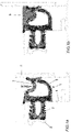
- the gasket denoted overall by reference numeral 1 is mounted by inserting the hooking foot 2 in a slot 3 formed in the front 4 of the oven, leaving the tubular head 5 thereof to protrude which works in hermetic abutment on the inner surface 6 of the door.
- a pocket 7 is formed, centrally whereto there is maximum load concentration determining a deformed shape indicated by the arrow, in the silicone material which constitutes it.
- this pocket 7 material 8 tends to accumulate, deriving from the cooking of food or from washing, as shown in Figure 1b , which creates major hygiene problems.
- the design and construction of the spigot are particularly delicate in that tears of the rubber have to be avoided during the extraction phase.
- the geometry is therefore relatively simple and all forms of undercutting are to be avoided.
- EP 2 330 356 A1 describes a gasket for pyrolytic ovens in which cleaning takes place at temperatures much higher than the cooking temperature, even up to 5/600°C, at which a silicone material would not resist. Therefore, the gasket is made at least partially in glass fibre, which is a material resistant to high temperatures.
- the task of the gasket is to collect and drain the fluids towards the exterior of the oven, preventing them from falling in an uncontrolled manner when the door is opened.
- the gasket has openings through which the fluids, made up of condensation and, to a smaller extent, of steam, are evacuated towards the exterior of the oven.
- Such a gasket would not be usable in a self-cleaning oven with washing fluids, in which the fluids must not stagnate in the gasket and remain inside the oven.
- the object of the present invention is to eliminate the disadvantages of the gaskets for food cooking ovens of the prior art.
- an object of the invention is to provide such a gasket whose lower crosspiece does not have areas of accumulation of materials during use and washing of the chamber of the oven.
- Another object of the invention is to provide such a gasket that has a longer working life compared to the existing ones, for the reduction in the deterioration of the lower crosspiece, which is the element most subject to thermal, chemical and mechanical attacks.
- a further object of the invention is to provide such a gasket which ensures an optimal seal.
- Yet another object of the invention is to provide such a gasket with more reliable angular joints.
- Last but not least an object of the invention is to provide such a gasket that is simple and economical to produce.
- the gasket for food cooking ovens is made up of a square or rectangular frame, comprising a lower crosspiece, an upper crosspiece and two side uprights, each provided with a stem or foot for hooking in a slot formed in the front of the oven and with a protruding tubular head, with internal cavity, which works in hermetic abutment on the inner surface of the door, wherein said lower crosspiece has a gutter appendage designed to convey the condensation which is formed on the inner surface of the door during cooking of the food and the washing fluids towards the interior of the chamber of the oven.
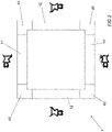
- a gasket 1 is schematised, made up of a frame of square or rectangular shape, comprising a lower crosspiece 10, an upper crosspiece 11 and two side uprights 12, as well as four overmoulded joining corners 40, one of which is shown in greater detail in Figures 5a and 5b and will be described here below.
- the upper crosspiece 11 and the two side uprights 12 are made up of profiles having the same section, provided with a foot or stem 2 for hooking in a slot 3 formed in the front 4 of the oven and with a protruding tubular head 5, with internal cavity 9, which works in hermetic abutment on the inner surface 6 of the door.
- the lower crosspiece 10 has the same configuration as the upper crosspiece and the side uprights (yet in theory could have also a different configuration) and differentiates from them in the provision of a gutter appendage 20 having the purpose of conveying the condensation formed on the door 6 during the cooking of the food or washing towards the interior of the chamber of the oven.
- the gutter appendage 20 is integrated in the extruded section of the crosspiece 10 and extends from the front end, intended to come into contact with the inner surface 6 of the door, towards the interior of the oven, with a slight slant downwards, to allow the sliding of the condensation and of other materials which were to deposit on the lower crosspiece.
- the length of the gutter appendage 20 is such as to cover at least the tubular head 5.
- the crosspiece 10 of Figures 3a and 3b could also be made by means of extrusion of two or more different materials (coextrusion).
- Such an integrated gutter protects the underlying section under stress of the crosspiece 10 and is without localised stresses with an increase in the working life of the gasket with respect to traditional solutions.
- Figure 3b which shows the gasket in working condition, shows how in its front part, which abuts against the inner surface 6 of the door, a protrusion 21 is provided along the upper edge, which constitutes an extension of the gutter appendage 20, a protrusion 22 along the lower edge and an intermediate protrusion 23, so as to have three points of contact on the door, to improve the seal also in the case of a dirty or encrusted surface.
- FIG. 4a, 4b differs from the previous one due to the fact that the gutter appendage, again denoted by reference numeral 20, is made as a separate part, restrained to the body of the gasket with an arrow-shaped interlocking 30 which interlocks into an appropriate seat 31 formed above the tubular head 5 of the crosspiece 10.
- the gutter appendage 20, which also comprises the protrusion 21 can be made in a specific, possible more "noble", material such as a fluoroelastomer (FKM) which, being resistant to chemical attacks, could give rise to an increase in duration.
- FKM fluoroelastomer
- the gutter appendage 20 can optionally be replaced, when worn, at a lower cost with respect to the replacement of the entire gasket.
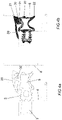
- Figures 5a and 5b show an angular element 40 for joining the various sides of the gasket, provided with an insert 41 which, fixed to the base of the corner, in the foot 2, performs the function of sealing and moreover, thanks to the presence of a fin 42 which is inserted in the internal cavity 9 of the tubular abutment head 5 ensures support thereof.
- This system optimises the coupling with the internal abutment plane 6 of the door.
- the drawings also show a small joining wall 43 between the portion of the angular element 40 designed to join to an upright 12 of the gasket and a section of gutter appendage 20 provided on the other portion of the angular element designed to join up with the lower crosspiece 10, to avoid infiltrations of condensation in the cavity below the gutter appendage 20.
- these additional elements would not be necessary in the corners of the union of the upper crosspiece 11 with the side uprights 12.
Landscapes
- Engineering & Computer Science (AREA)
- General Engineering & Computer Science (AREA)
- Mechanical Engineering (AREA)
- Chemical & Material Sciences (AREA)
- Combustion & Propulsion (AREA)
- Gasket Seals (AREA)
- General Preparation And Processing Of Foods (AREA)
Abstract
Description
- The subject of the present invention is a gasket in elastomeric material for ovens for cooking food, in particular for industrial ovens.
- Many of the industrial ovens currently available on the market are equipped with a system of self-cleaning, with feeding of detergent fluids, which make them, in some respects, similar to a dishwasher.
- These ovens for cooking food are equipped with a silicone sealing gasket, in the form of a frame, made by "welding", by co-vulcanising separate corners, four rectilinear extruded sections, all having the same cross section, such as for example shown in the accompanying
Figure 1a relating to the lower crosspiece, which is the one most stressed. - The gasket denoted overall by reference numeral 1 is mounted by inserting the hooking
foot 2 in aslot 3 formed in thefront 4 of the oven, leaving thetubular head 5 thereof to protrude which works in hermetic abutment on theinner surface 6 of the door. - As can be seen, in condition of use, a
pocket 7 is formed, centrally whereto there is maximum load concentration determining a deformed shape indicated by the arrow, in the silicone material which constitutes it. In thispocket 7material 8 tends to accumulate, deriving from the cooking of food or from washing, as shown inFigure 1b , which creates major hygiene problems. - In addition to the evident hygiene problems, particularly greasy food and/or chemically aggressive washing agents generate an accumulation on the inside which is deposited through gravity in the
pocket 7 chemically attacking the elastomeric component and contributing to determining a rapid deterioration of the gasket, with possible breakage in the aforementioned point of maximum load concentration in the lower crosspiece. In fact thedeposits 8 that are accumulated in thepocket 7 should be removed as soon as possible from the gasket in that the damage is proportional to the time of exposure and to the temperature. Resorting to frequent washes with the use of detergents and rinse aids that also chemically attack the silicone material further contributes to deterioration of the gasket. Another problem of known gaskets is the joining of the four sections that constitute it which, in order to obtain a hollow section joining angle, requires the prior introduction therein of a metal spigot which, at the end of moulding, has to be removed. - The design and construction of the spigot are particularly delicate in that tears of the rubber have to be avoided during the extraction phase. The geometry is therefore relatively simple and all forms of undercutting are to be avoided.
- However, this leads to a cavity in the area of the corners which has to be sealed, at least in the area of the foot of the gasket, to avoid the entry of dirt.
-
EP 2 330 356 A1 - The object of the present invention is to eliminate the disadvantages of the gaskets for food cooking ovens of the prior art.
- More particularly, an object of the invention is to provide such a gasket whose lower crosspiece does not have areas of accumulation of materials during use and washing of the chamber of the oven.
- Another object of the invention is to provide such a gasket that has a longer working life compared to the existing ones, for the reduction in the deterioration of the lower crosspiece, which is the element most subject to thermal, chemical and mechanical attacks.
- A further object of the invention is to provide such a gasket which ensures an optimal seal.
- Yet another object of the invention is to provide such a gasket with more reliable angular joints.
- Last but not least an object of the invention is to provide such a gasket that is simple and economical to produce.
- These and other objects are achieved by the gasket for food cooking ovens according to the invention which has the features of the appended independent claim 1.
- Advantageous embodiments of the invention are disclosed in the dependent claims.
- Substantially, the gasket for food cooking ovens according to the invention is made up of a square or rectangular frame, comprising a lower crosspiece, an upper crosspiece and two side uprights, each provided with a stem or foot for hooking in a slot formed in the front of the oven and with a protruding tubular head, with internal cavity, which works in hermetic abutment on the inner surface of the door, wherein said lower crosspiece has a gutter appendage designed to convey the condensation which is formed on the inner surface of the door during cooking of the food and the washing fluids towards the interior of the chamber of the oven.
- Further features of the invention will be made clearer by the following detailed description, referred to its purely exemplary and therefore non-limiting embodiments, illustrated in the accompanying drawings, in which:
-
Figures 1a, 1b are sectioned views of the lower crosspiece of a gasket of the prior art, showing the accumulation of material that occurs in a pocket of the same. -
Figure 2 is an extremely schematic plan view of a gasket according to the invention with the overmoulded corners that constitute it, showing the sections of the four sides, to highlight the structural differences of the gasket in its lower crosspiece; -
Figures 3a, 3b show the section of the lower crosspiece, respectively in rest condition, before assembly, and in working condition, after assembly and with the door closed; -
Figures 4a, 4b are views similar toFigures 3a, 3b of a different embodiment of the gasket in its lower crosspiece; -
Figure 5a is an axonometric view of an angular element used for the joining of the sides of the gasket; -
Figure 5b is a blown-up view of the angular element ofFigure 5a . - In the drawings listed above, identical or similar elements are identified by the same reference numerals.
- In the description of the gasket according to the invention the same references introduced in
Figures 1a, 1b relating to the prior art will be used. - In the plan view of
Figure 2 a gasket 1 is schematised, made up of a frame of square or rectangular shape, comprising alower crosspiece 10, anupper crosspiece 11 and twoside uprights 12, as well as fourovermoulded joining corners 40, one of which is shown in greater detail inFigures 5a and 5b and will be described here below. - The
upper crosspiece 11 and the twoside uprights 12 are made up of profiles having the same section, provided with a foot orstem 2 for hooking in aslot 3 formed in thefront 4 of the oven and with a protrudingtubular head 5, withinternal cavity 9, which works in hermetic abutment on theinner surface 6 of the door. - The
lower crosspiece 10 has the same configuration as the upper crosspiece and the side uprights (yet in theory could have also a different configuration) and differentiates from them in the provision of agutter appendage 20 having the purpose of conveying the condensation formed on thedoor 6 during the cooking of the food or washing towards the interior of the chamber of the oven. - In the embodiment of
Figures 3a, 3b , thegutter appendage 20 is integrated in the extruded section of thecrosspiece 10 and extends from the front end, intended to come into contact with theinner surface 6 of the door, towards the interior of the oven, with a slight slant downwards, to allow the sliding of the condensation and of other materials which were to deposit on the lower crosspiece. The length of thegutter appendage 20 is such as to cover at least thetubular head 5. - The
crosspiece 10 ofFigures 3a and 3b could also be made by means of extrusion of two or more different materials (coextrusion). - Such an integrated gutter protects the underlying section under stress of the
crosspiece 10 and is without localised stresses with an increase in the working life of the gasket with respect to traditional solutions. -
Figure 3b , which shows the gasket in working condition, shows how in its front part, which abuts against theinner surface 6 of the door, aprotrusion 21 is provided along the upper edge, which constitutes an extension of thegutter appendage 20, aprotrusion 22 along the lower edge and anintermediate protrusion 23, so as to have three points of contact on the door, to improve the seal also in the case of a dirty or encrusted surface. - These three points of contact also occur in the other three sides of the gasket, should profiles of the same configuration be used, as shown in the drawings.
- The embodiment of
Figures 4a, 4b differs from the previous one due to the fact that the gutter appendage, again denoted byreference numeral 20, is made as a separate part, restrained to the body of the gasket with an arrow-shaped interlocking 30 which interlocks into anappropriate seat 31 formed above thetubular head 5 of thecrosspiece 10. - According to this embodiment the
gutter appendage 20, which also comprises theprotrusion 21, can be made in a specific, possible more "noble", material such as a fluoroelastomer (FKM) which, being resistant to chemical attacks, could give rise to an increase in duration. - Moreover, the
gutter appendage 20 can optionally be replaced, when worn, at a lower cost with respect to the replacement of the entire gasket. -
Figures 5a and 5b show anangular element 40 for joining the various sides of the gasket, provided with aninsert 41 which, fixed to the base of the corner, in thefoot 2, performs the function of sealing and moreover, thanks to the presence of afin 42 which is inserted in theinternal cavity 9 of thetubular abutment head 5 ensures support thereof. This system optimises the coupling with theinternal abutment plane 6 of the door. The drawings also show asmall joining wall 43 between the portion of theangular element 40 designed to join to an upright 12 of the gasket and a section ofgutter appendage 20 provided on the other portion of the angular element designed to join up with thelower crosspiece 10, to avoid infiltrations of condensation in the cavity below thegutter appendage 20. Naturally these additional elements would not be necessary in the corners of the union of theupper crosspiece 11 with theside uprights 12. - From what has been disclosed the advantages of the gasket according to the invention appear clear, due to the lack of the pocket for collection of material which is formed in the gaskets of the prior art.
- Naturally the invention is not limited to the particular embodiments previously described and illustrated in the accompanying drawings, but numerous detailed changes may be made thereto, within the reach of the person skilled in the art, without thereby departing from the scope of the same invention, as defined in the following claims.
Claims (10)
- Gasket in elastomer (1) for food cooking ovens consisting of a square or rectangular frame, comprising a lower crosspiece (10), an upper crosspiece (11) and two side uprights (12), each provided with a foot or stem (2) for hooking in a slot (3) formed in the front (4) of the oven and with a protruding tubular head (5), with internal cavity (9), which works in hermetic abutment on the inner surface (6) of the door, characterised in that said lower crosspiece (10) has a gutter appendage (20) designed to convey the condensation that forms on the inner surface (6) of the door during cooking of food and the washing fluids towards the inside of the oven chamber.
- Gasket according to claim 1, characterised in that said gutter appendage (20) extends from the end of the gasket, intended to come into contact with the inner surface (6) of the door, towards the inside of the oven, with a slight slant downwards.
- Gasket according to claim 1 or 2, characterised in that said gutter appendage (20) is integrated in the extruded section of the crosspiece (10).
- Gasket according to claim 1 or 2, characterised in that said gutter appendage (20) is made as a separate piece, which is fastened to the body of the gasket with an interlocking (30) which interlocks in a corresponding seat (31) obtained above the tubular head (5) of the crosspiece (10).
- Gasket according to claim 4, characterised in that said gutter appendage (20) is made in a specific material, possibly different from the silicone material from which the gasket (1) is made.
- Gasket according to claim 5, characterised in that said gutter appendage (20) is made by means of a coextrusion process.
- Gasket according to claim 5 or 6, characterised in that said gutter appendage (20) is made in fluoroelastomer (FKM).
- Gasket according to any one of the preceding claims, characterised in that in its front part, which abuts against the inner surface (6) of the door, there is a protrusion (21) along the upper edge, which constitutes an extension of the gutter appendage (20), a protrusion (22) along the lower edge, and an intermediate protrusion (23), so as to have three points of contact on the glass (6), to improve sealing.
- Gasket according to any one of the preceding claims, characterised in that it provides an angular element (40), made through overmoulding designed to join the sides of the gasket, provided with an insert (41) fixed in the foot (2), and having a fin (42) which is inserted in the internal cavity (9) of the tubular abutment head (5) ensuring support thereof.
- Gasket according to claim 9, characterised in that said angular element (40) intended to join the lower crosspiece (10) to the side uprights (12) has a section of gutter appendage (20) on its portion designed to join to the lower crosspiece 10, joined with a small joining wall (43) to the portion of the angular element (40) designed to join to an upright (12) in order to prevent lateral infiltrations.
Applications Claiming Priority (1)
| Application Number | Priority Date | Filing Date | Title |
|---|---|---|---|
| IT102020000026293A IT202000026293A1 (en) | 2020-11-04 | 2020-11-04 | GASKET FOR FOOD COOKING OVENS |
Publications (3)
| Publication Number | Publication Date |
|---|---|
| EP3995745A1 true EP3995745A1 (en) | 2022-05-11 |
| EP3995745B1 EP3995745B1 (en) | 2024-03-13 |
| EP3995745C0 EP3995745C0 (en) | 2024-03-13 |
Family
ID=74194947
Family Applications (1)
| Application Number | Title | Priority Date | Filing Date |
|---|---|---|---|
| EP21205170.0A Active EP3995745B1 (en) | 2020-11-04 | 2021-10-28 | Gasket for food cooking ovens |
Country Status (5)
| Country | Link |
|---|---|
| EP (1) | EP3995745B1 (en) |
| ES (1) | ES2984416T3 (en) |
| HU (1) | HUE066786T2 (en) |
| IT (1) | IT202000026293A1 (en) |
| PL (1) | PL3995745T3 (en) |
Citations (4)
| Publication number | Priority date | Publication date | Assignee | Title |
|---|---|---|---|---|
| US5095657A (en) * | 1990-10-26 | 1992-03-17 | Marsh Richard B | Door seal |
| DE4437838A1 (en) * | 1994-10-22 | 1996-04-25 | Heerig Hans Walter | Food heater with cooling space and door seal |
| DE10044376A1 (en) * | 2000-09-08 | 2002-04-04 | Aeg Hausgeraete Gmbh | Baking oven has door seal forming condensate drainage surface sloping from contact point on door to contact point on oven to divert condensate to oven floor |
| EP2330356A1 (en) | 2009-12-02 | 2011-06-08 | BSH Bosch und Siemens Hausgeräte GmbH | Door seal strip and cooking device |
-
2020
- 2020-11-04 IT IT102020000026293A patent/IT202000026293A1/en unknown
-
2021
- 2021-10-28 ES ES21205170T patent/ES2984416T3/en active Active
- 2021-10-28 PL PL21205170.0T patent/PL3995745T3/en unknown
- 2021-10-28 EP EP21205170.0A patent/EP3995745B1/en active Active
- 2021-10-28 HU HUE21205170A patent/HUE066786T2/en unknown
Patent Citations (4)
| Publication number | Priority date | Publication date | Assignee | Title |
|---|---|---|---|---|
| US5095657A (en) * | 1990-10-26 | 1992-03-17 | Marsh Richard B | Door seal |
| DE4437838A1 (en) * | 1994-10-22 | 1996-04-25 | Heerig Hans Walter | Food heater with cooling space and door seal |
| DE10044376A1 (en) * | 2000-09-08 | 2002-04-04 | Aeg Hausgeraete Gmbh | Baking oven has door seal forming condensate drainage surface sloping from contact point on door to contact point on oven to divert condensate to oven floor |
| EP2330356A1 (en) | 2009-12-02 | 2011-06-08 | BSH Bosch und Siemens Hausgeräte GmbH | Door seal strip and cooking device |
Also Published As
| Publication number | Publication date |
|---|---|
| ES2984416T3 (en) | 2024-10-29 |
| EP3995745B1 (en) | 2024-03-13 |
| IT202000026293A1 (en) | 2022-05-04 |
| EP3995745C0 (en) | 2024-03-13 |
| HUE066786T2 (en) | 2024-09-28 |
| PL3995745T3 (en) | 2024-06-17 |
Similar Documents
| Publication | Publication Date | Title |
|---|---|---|
| US8196931B2 (en) | Gap molding and method | |
| EP3995745B1 (en) | Gasket for food cooking ovens | |
| KR102046052B1 (en) | Sealing member and dish washer having the same | |
| JP5582724B2 (en) | Furnace bulkhead | |
| CN108309192B (en) | Sealing strip for dishwashers and dishwashers having the same | |
| KR20180034547A (en) | Dishwashers, especially household dishwashers | |
| US20070240701A9 (en) | Oven | |
| CN101296645B (en) | Dishwasher with plastic frame parts secured to disposal container | |
| KR102662674B1 (en) | Dishwasher | |
| CN111557630A (en) | A door assembly and household appliance | |
| KR100912036B1 (en) | Windows with dew condensation gaskets | |
| AU2011351686B2 (en) | A cooking device comprising a covering member | |
| CN210842919U (en) | Sealing strip for dish-washing machine and dish-washing machine | |
| CZ385997A3 (en) | Frame structure consisting of struts and cross beams in the form of hollow sections | |
| JP6547937B2 (en) | Bathroom counter | |
| CN214998452U (en) | Fan system and range hood applying same | |
| CN223746316U (en) | Dish washer with seal structure | |
| JP4349212B2 (en) | dishwasher | |
| CN216618544U (en) | No long-pending sediment motor shaft sealing member and motor shaft seal structure | |
| TW201300067A (en) | Dishwasher | |
| KR200215082Y1 (en) | Door seal packing structure for dish washer | |
| KR102638300B1 (en) | Wall panel | |
| SI24688A (en) | Sealing for the door of a household appliance | |
| WO2012089455A2 (en) | A cooking device comprising a door having a sealing element | |
| KR100239516B1 (en) | Dishwasher |
Legal Events
| Date | Code | Title | Description |
|---|---|---|---|
| PUAI | Public reference made under article 153(3) epc to a published international application that has entered the european phase |
Free format text: ORIGINAL CODE: 0009012 |
|
| STAA | Information on the status of an ep patent application or granted ep patent |
Free format text: STATUS: THE APPLICATION HAS BEEN PUBLISHED |
|
| AK | Designated contracting states |
Kind code of ref document: A1 Designated state(s): AL AT BE BG CH CY CZ DE DK EE ES FI FR GB GR HR HU IE IS IT LI LT LU LV MC MK MT NL NO PL PT RO RS SE SI SK SM TR |
|
| STAA | Information on the status of an ep patent application or granted ep patent |
Free format text: STATUS: REQUEST FOR EXAMINATION WAS MADE |
|
| 17P | Request for examination filed |
Effective date: 20220915 |
|
| RBV | Designated contracting states (corrected) |
Designated state(s): AL AT BE BG CH CY CZ DE DK EE ES FI FR GB GR HR HU IE IS IT LI LT LU LV MC MK MT NL NO PL PT RO RS SE SI SK SM TR |
|
| GRAP | Despatch of communication of intention to grant a patent |
Free format text: ORIGINAL CODE: EPIDOSNIGR1 |
|
| STAA | Information on the status of an ep patent application or granted ep patent |
Free format text: STATUS: GRANT OF PATENT IS INTENDED |
|
| INTG | Intention to grant announced |
Effective date: 20231204 |
|
| GRAS | Grant fee paid |
Free format text: ORIGINAL CODE: EPIDOSNIGR3 |
|
| GRAA | (expected) grant |
Free format text: ORIGINAL CODE: 0009210 |
|
| STAA | Information on the status of an ep patent application or granted ep patent |
Free format text: STATUS: THE PATENT HAS BEEN GRANTED |
|
| AK | Designated contracting states |
Kind code of ref document: B1 Designated state(s): AL AT BE BG CH CY CZ DE DK EE ES FI FR GB GR HR HU IE IS IT LI LT LU LV MC MK MT NL NO PL PT RO RS SE SI SK SM TR |
|
| REG | Reference to a national code |
Ref country code: GB Ref legal event code: FG4D |
|
| REG | Reference to a national code |
Ref country code: CH Ref legal event code: EP |
|
| REG | Reference to a national code |
Ref country code: DE Ref legal event code: R096 Ref document number: 602021010349 Country of ref document: DE |
|
| REG | Reference to a national code |
Ref country code: IE Ref legal event code: FG4D |
|
| U01 | Request for unitary effect filed |
Effective date: 20240411 |
|
| U07 | Unitary effect registered |
Designated state(s): AT BE BG DE DK EE FI FR IT LT LU LV MT NL PT SE SI Effective date: 20240418 |
|
| REG | Reference to a national code |
Ref country code: GR Ref legal event code: EP Ref document number: 20240400909 Country of ref document: GR Effective date: 20240516 |
|
| PG25 | Lapsed in a contracting state [announced via postgrant information from national office to epo] |
Ref country code: RS Free format text: LAPSE BECAUSE OF FAILURE TO SUBMIT A TRANSLATION OF THE DESCRIPTION OR TO PAY THE FEE WITHIN THE PRESCRIBED TIME-LIMIT Effective date: 20240613 Ref country code: HR Free format text: LAPSE BECAUSE OF FAILURE TO SUBMIT A TRANSLATION OF THE DESCRIPTION OR TO PAY THE FEE WITHIN THE PRESCRIBED TIME-LIMIT Effective date: 20240313 |
|
| PG25 | Lapsed in a contracting state [announced via postgrant information from national office to epo] |
Ref country code: RS Free format text: LAPSE BECAUSE OF FAILURE TO SUBMIT A TRANSLATION OF THE DESCRIPTION OR TO PAY THE FEE WITHIN THE PRESCRIBED TIME-LIMIT Effective date: 20240613 Ref country code: NO Free format text: LAPSE BECAUSE OF FAILURE TO SUBMIT A TRANSLATION OF THE DESCRIPTION OR TO PAY THE FEE WITHIN THE PRESCRIBED TIME-LIMIT Effective date: 20240613 Ref country code: HR Free format text: LAPSE BECAUSE OF FAILURE TO SUBMIT A TRANSLATION OF THE DESCRIPTION OR TO PAY THE FEE WITHIN THE PRESCRIBED TIME-LIMIT Effective date: 20240313 |
|
| REG | Reference to a national code |
Ref country code: HU Ref legal event code: AG4A Ref document number: E066786 Country of ref document: HU |
|
| PG25 | Lapsed in a contracting state [announced via postgrant information from national office to epo] |
Ref country code: IS Free format text: LAPSE BECAUSE OF FAILURE TO SUBMIT A TRANSLATION OF THE DESCRIPTION OR TO PAY THE FEE WITHIN THE PRESCRIBED TIME-LIMIT Effective date: 20240713 |
|
| U20 | Renewal fee for the european patent with unitary effect paid |
Year of fee payment: 4 Effective date: 20240905 |
|
| PG25 | Lapsed in a contracting state [announced via postgrant information from national office to epo] |
Ref country code: SM Free format text: LAPSE BECAUSE OF FAILURE TO SUBMIT A TRANSLATION OF THE DESCRIPTION OR TO PAY THE FEE WITHIN THE PRESCRIBED TIME-LIMIT Effective date: 20240313 |
|
| PG25 | Lapsed in a contracting state [announced via postgrant information from national office to epo] |
Ref country code: CZ Free format text: LAPSE BECAUSE OF FAILURE TO SUBMIT A TRANSLATION OF THE DESCRIPTION OR TO PAY THE FEE WITHIN THE PRESCRIBED TIME-LIMIT Effective date: 20240313 |
|
| PG25 | Lapsed in a contracting state [announced via postgrant information from national office to epo] |
Ref country code: SK Free format text: LAPSE BECAUSE OF FAILURE TO SUBMIT A TRANSLATION OF THE DESCRIPTION OR TO PAY THE FEE WITHIN THE PRESCRIBED TIME-LIMIT Effective date: 20240313 |
|
| REG | Reference to a national code |
Ref country code: ES Ref legal event code: FG2A Ref document number: 2984416 Country of ref document: ES Kind code of ref document: T3 Effective date: 20241029 |
|
| PG25 | Lapsed in a contracting state [announced via postgrant information from national office to epo] |
Ref country code: SM Free format text: LAPSE BECAUSE OF FAILURE TO SUBMIT A TRANSLATION OF THE DESCRIPTION OR TO PAY THE FEE WITHIN THE PRESCRIBED TIME-LIMIT Effective date: 20240313 Ref country code: SK Free format text: LAPSE BECAUSE OF FAILURE TO SUBMIT A TRANSLATION OF THE DESCRIPTION OR TO PAY THE FEE WITHIN THE PRESCRIBED TIME-LIMIT Effective date: 20240313 Ref country code: IS Free format text: LAPSE BECAUSE OF FAILURE TO SUBMIT A TRANSLATION OF THE DESCRIPTION OR TO PAY THE FEE WITHIN THE PRESCRIBED TIME-LIMIT Effective date: 20240713 Ref country code: CZ Free format text: LAPSE BECAUSE OF FAILURE TO SUBMIT A TRANSLATION OF THE DESCRIPTION OR TO PAY THE FEE WITHIN THE PRESCRIBED TIME-LIMIT Effective date: 20240313 |
|
| REG | Reference to a national code |
Ref country code: DE Ref legal event code: R097 Ref document number: 602021010349 Country of ref document: DE |
|
| PLBE | No opposition filed within time limit |
Free format text: ORIGINAL CODE: 0009261 |
|
| STAA | Information on the status of an ep patent application or granted ep patent |
Free format text: STATUS: NO OPPOSITION FILED WITHIN TIME LIMIT |
|
| 26N | No opposition filed |
Effective date: 20241216 |
|
| PG25 | Lapsed in a contracting state [announced via postgrant information from national office to epo] |
Ref country code: MC Free format text: LAPSE BECAUSE OF FAILURE TO SUBMIT A TRANSLATION OF THE DESCRIPTION OR TO PAY THE FEE WITHIN THE PRESCRIBED TIME-LIMIT Effective date: 20240313 |
|
| REG | Reference to a national code |
Ref country code: CH Ref legal event code: U11 Free format text: ST27 STATUS EVENT CODE: U-0-0-U10-U11 (AS PROVIDED BY THE NATIONAL OFFICE) Effective date: 20251101 |
|
| PGFP | Annual fee paid to national office [announced via postgrant information from national office to epo] |
Ref country code: HU Payment date: 20251027 Year of fee payment: 5 |
|
| U20 | Renewal fee for the european patent with unitary effect paid |
Year of fee payment: 5 Effective date: 20251017 |
|
| PGFP | Annual fee paid to national office [announced via postgrant information from national office to epo] |
Ref country code: GB Payment date: 20251017 Year of fee payment: 5 |
|
| PGFP | Annual fee paid to national office [announced via postgrant information from national office to epo] |
Ref country code: TR Payment date: 20251027 Year of fee payment: 5 Ref country code: GR Payment date: 20251022 Year of fee payment: 5 |
|
| PGFP | Annual fee paid to national office [announced via postgrant information from national office to epo] |
Ref country code: CH Payment date: 20251101 Year of fee payment: 5 |
|
| PGFP | Annual fee paid to national office [announced via postgrant information from national office to epo] |
Ref country code: IE Payment date: 20251024 Year of fee payment: 5 |
|
| PGFP | Annual fee paid to national office [announced via postgrant information from national office to epo] |
Ref country code: PL Payment date: 20251022 Year of fee payment: 5 |
|
| PGFP | Annual fee paid to national office [announced via postgrant information from national office to epo] |
Ref country code: RO Payment date: 20251023 Year of fee payment: 5 |
|
| PGFP | Annual fee paid to national office [announced via postgrant information from national office to epo] |
Ref country code: ES Payment date: 20251216 Year of fee payment: 5 |
|
| PG25 | Lapsed in a contracting state [announced via postgrant information from national office to epo] |
Ref country code: CY Free format text: LAPSE BECAUSE OF FAILURE TO SUBMIT A TRANSLATION OF THE DESCRIPTION OR TO PAY THE FEE WITHIN THE PRESCRIBED TIME-LIMIT; INVALID AB INITIO Effective date: 20211028 |