EP3995739A1 - Burning apparatus for railway repair - Google Patents
Burning apparatus for railway repair Download PDFInfo
- Publication number
- EP3995739A1 EP3995739A1 EP20205851.7A EP20205851A EP3995739A1 EP 3995739 A1 EP3995739 A1 EP 3995739A1 EP 20205851 A EP20205851 A EP 20205851A EP 3995739 A1 EP3995739 A1 EP 3995739A1
- Authority
- EP
- European Patent Office
- Prior art keywords
- assembly
- burning
- air
- air compressor
- combustion
- Prior art date
- Legal status (The legal status is an assumption and is not a legal conclusion. Google has not performed a legal analysis and makes no representation as to the accuracy of the status listed.)
- Granted
Links
Images







Classifications
-
- F—MECHANICAL ENGINEERING; LIGHTING; HEATING; WEAPONS; BLASTING
- F23—COMBUSTION APPARATUS; COMBUSTION PROCESSES
- F23D—BURNERS
- F23D99/00—Subject matter not provided for in other groups of this subclass
- F23D99/002—Burners specially adapted for specific applications
- F23D99/004—Burners specially adapted for specific applications for use in particular heating operations
-
- B—PERFORMING OPERATIONS; TRANSPORTING
- B23—MACHINE TOOLS; METAL-WORKING NOT OTHERWISE PROVIDED FOR
- B23K—SOLDERING OR UNSOLDERING; WELDING; CLADDING OR PLATING BY SOLDERING OR WELDING; CUTTING BY APPLYING HEAT LOCALLY, e.g. FLAME CUTTING; WORKING BY LASER BEAM
- B23K23/00—Alumino-thermic welding
-
- B—PERFORMING OPERATIONS; TRANSPORTING
- B23—MACHINE TOOLS; METAL-WORKING NOT OTHERWISE PROVIDED FOR
- B23K—SOLDERING OR UNSOLDERING; WELDING; CLADDING OR PLATING BY SOLDERING OR WELDING; CUTTING BY APPLYING HEAT LOCALLY, e.g. FLAME CUTTING; WORKING BY LASER BEAM
- B23K37/00—Auxiliary devices or processes, not specially adapted for a procedure covered by only one of the other main groups of this subclass
-
- E—FIXED CONSTRUCTIONS
- E01—CONSTRUCTION OF ROADS, RAILWAYS, OR BRIDGES
- E01B—PERMANENT WAY; PERMANENT-WAY TOOLS; MACHINES FOR MAKING RAILWAYS OF ALL KINDS
- E01B31/00—Working rails, sleepers, baseplates, or the like, in or on the line; Machines, tools, or auxiliary devices specially designed therefor
- E01B31/02—Working rail or other metal track components on the spot
-
- E—FIXED CONSTRUCTIONS
- E01—CONSTRUCTION OF ROADS, RAILWAYS, OR BRIDGES
- E01B—PERMANENT WAY; PERMANENT-WAY TOOLS; MACHINES FOR MAKING RAILWAYS OF ALL KINDS
- E01B31/00—Working rails, sleepers, baseplates, or the like, in or on the line; Machines, tools, or auxiliary devices specially designed therefor
- E01B31/02—Working rail or other metal track components on the spot
- E01B31/18—Reconditioning or repairing worn or damaged parts on the spot, e.g. applying inlays, building-up rails by welding; Heating or cooling of parts on the spot, e.g. for reducing joint gaps, for hardening rails
-
- F—MECHANICAL ENGINEERING; LIGHTING; HEATING; WEAPONS; BLASTING
- F23—COMBUSTION APPARATUS; COMBUSTION PROCESSES
- F23D—BURNERS
- F23D14/00—Burners for combustion of a gas, e.g. of a gas stored under pressure as a liquid
- F23D14/34—Burners specially adapted for use with means for pressurising the gaseous fuel or the combustion air
-
- F—MECHANICAL ENGINEERING; LIGHTING; HEATING; WEAPONS; BLASTING
- F23—COMBUSTION APPARATUS; COMBUSTION PROCESSES
- F23D—BURNERS
- F23D14/00—Burners for combustion of a gas, e.g. of a gas stored under pressure as a liquid
- F23D14/34—Burners specially adapted for use with means for pressurising the gaseous fuel or the combustion air
- F23D14/36—Burners specially adapted for use with means for pressurising the gaseous fuel or the combustion air in which the compressor and burner form a single unit
-
- F—MECHANICAL ENGINEERING; LIGHTING; HEATING; WEAPONS; BLASTING
- F23—COMBUSTION APPARATUS; COMBUSTION PROCESSES
- F23D—BURNERS
- F23D14/00—Burners for combustion of a gas, e.g. of a gas stored under pressure as a liquid
- F23D14/38—Torches, e.g. for brazing or heating
-
- F—MECHANICAL ENGINEERING; LIGHTING; HEATING; WEAPONS; BLASTING
- F23—COMBUSTION APPARATUS; COMBUSTION PROCESSES
- F23D—BURNERS
- F23D14/00—Burners for combustion of a gas, e.g. of a gas stored under pressure as a liquid
- F23D14/38—Torches, e.g. for brazing or heating
- F23D14/40—Torches, e.g. for brazing or heating for welding
-
- B—PERFORMING OPERATIONS; TRANSPORTING
- B23—MACHINE TOOLS; METAL-WORKING NOT OTHERWISE PROVIDED FOR
- B23K—SOLDERING OR UNSOLDERING; WELDING; CLADDING OR PLATING BY SOLDERING OR WELDING; CUTTING BY APPLYING HEAT LOCALLY, e.g. FLAME CUTTING; WORKING BY LASER BEAM
- B23K2101/00—Articles made by soldering, welding or cutting
- B23K2101/26—Railway- or like rails
-
- B—PERFORMING OPERATIONS; TRANSPORTING
- B23—MACHINE TOOLS; METAL-WORKING NOT OTHERWISE PROVIDED FOR
- B23P—METAL-WORKING NOT OTHERWISE PROVIDED FOR; COMBINED OPERATIONS; UNIVERSAL MACHINE TOOLS
- B23P6/00—Restoring or reconditioning objects
-
- E—FIXED CONSTRUCTIONS
- E01—CONSTRUCTION OF ROADS, RAILWAYS, OR BRIDGES
- E01B—PERMANENT WAY; PERMANENT-WAY TOOLS; MACHINES FOR MAKING RAILWAYS OF ALL KINDS
- E01B29/00—Laying, rebuilding, or taking-up tracks; Tools or machines therefor
- E01B29/42—Undetachably joining or fastening track components in or on the track, e.g. by welding, by gluing; Pre-assembling track components by gluing; Sealing joints with filling components
- E01B29/44—Methods for effecting joining of rails in the track, e.g. taking account of ambient temperature
-
- F—MECHANICAL ENGINEERING; LIGHTING; HEATING; WEAPONS; BLASTING
- F23—COMBUSTION APPARATUS; COMBUSTION PROCESSES
- F23K—FEEDING FUEL TO COMBUSTION APPARATUS
- F23K5/00—Feeding or distributing other fuel to combustion apparatus
- F23K5/002—Gaseous fuel
- F23K5/007—Details
-
- Y—GENERAL TAGGING OF NEW TECHNOLOGICAL DEVELOPMENTS; GENERAL TAGGING OF CROSS-SECTIONAL TECHNOLOGIES SPANNING OVER SEVERAL SECTIONS OF THE IPC; TECHNICAL SUBJECTS COVERED BY FORMER USPC CROSS-REFERENCE ART COLLECTIONS [XRACs] AND DIGESTS
- Y02—TECHNOLOGIES OR APPLICATIONS FOR MITIGATION OR ADAPTATION AGAINST CLIMATE CHANGE
- Y02T—CLIMATE CHANGE MITIGATION TECHNOLOGIES RELATED TO TRANSPORTATION
- Y02T10/00—Road transport of goods or passengers
- Y02T10/10—Internal combustion engine [ICE] based vehicles
- Y02T10/12—Improving ICE efficiencies
Definitions
- the present invention relates to a burning apparatus for railway repair, more particularly for aluminothermic welding.
- aluminothermic welding was invented to weld rail tracks with the development of the metallurgical and chemical industries.
- a welding operator should heat the end faces of these rail ends opposite each other in the welding gap. This heating process aims to remove any moisture that may exist in a welding mold. Furthermore, increasing the temperature of the rail ends can slow down the cooling of the heated weld. In this way, a welding operator can obtain a desired certain metallic structure in the welding gap.
- a welding operator takes much effort and energy to move a conventional preheating burner equipped with an air compressor on and off the railway tracks.
- the conventional preheating burner is comparatively huge and heavy because the air compressor is usually disposed on the side of the preheating burner. Thus, a conventional preheating burner does not provide a thinner and lighter burning apparatus for railway repair.
- the objective of the present invention is to provide a burning apparatus for railway repair, and more particularly a burning apparatus that provides a thinner and lighter burning apparatus for railway repair.
- a first aspect of the present invention provides a burning apparatus for railway repair, defining an axis and comprising: an air compressor assembly including an inlet opening and an outlet opening, and a combustion assembly connected to the outlet opening of the air compressor assembly, wherein the air compressor assembly and the combustion assembly are axially disposed along the axis, and wherein the air compressor assembly compresses air into the combustion assembly.
- the air compressor assembly further comprises: a body axially disposed along the axis, a motor including a motor shaft and disposed in the body, and a propeller driven by the motor through the motor shaft and guiding air into the body.
- the body comprises: an outer housing, and an inner housing disposed in the outer housing and connected to the outer housing, the motor disposed therein, wherein the inner housing and the outer housing defining an air passage therebetween, and the propeller guides air from the air compressor assembly into the combustion assembly through the air passage.
- the body further includes a rib connecting between the outer housing and the inner housing in the air passage.
- the air compressor assembly further comprises a hood configured for guiding air into the inlet opening of the air compressor assembly.
- the air compressor assembly further comprises: a plastic mounting plate receiving the propeller and disposed between the hood and the body, and a metal mounting plate disposed between the plastic mounting plate and the body to strengthen the air compressor assembly.
- the inner housing of the body includes an inner housing opening which allows air to flow from the air passage into the inner housing for cooling the motor.
- the combustion assembly includes: a combustion assembly housing including an inlet opening and an outlet opening, the inlet opening of the combustion assembly housing communicating with the outlet opening of the air compressor assembly, a fuel means for providing fuel into the combustion assembly, and an ignition means for igniting fuel, wherein the ignition means ignites the fuel in the combustion assembly to produce a flame.
- the combustion assembly further includes a burning tube assembly disposed in the combustion assembly housing, the burning tube assembly comprising: an inlet disc, an outlet disc, and a burning tube body configured to be hollow and disposed along the axis in the combustion assembly housing and between the inlet disc and the outlet disc, wherein the burning tube body and the combustion assembly housing define an air channel therebetween, and wherein the air passage of the air compressor assembly, the air channel of the combustion assembly, the burning tube body, and the outlet opening of the combustion assembly are designed to be communicated.
- the burning tube body includes openings designed along the burning tube body to control the amount of air entering from the air channel into the burning tube body, wherein the combustion of the mixture of the fuel and air happens in the burning tube body.
- the combustion assembly includes a sensor for monitoring and detecting the presence of flame.
- the fuel means is connected to a fuel providing device, and the ignition means is connected to an electrical device.
- the body of the air compressor assembly can be constructed as integral, and the hood and the body can be constructed as integral.
- a sixteenth aspect of the present invention provides a preheating device for railway repair, comprising: a preheating device body, and the burning apparatus of any of the first to fifteenth aspects disposed in the preheating device, wherein the preheating device can be operated on the railway tracks to heat the railway.
- the present invention aims to provide a thinner and lighter burning apparatus for railway repair and cooling the combustion assembly.
- Fig. 1 is a perspective view of a burning apparatus for heating railway tracks in accordance with the preferred embodiment of the present invention.
- Fig. 2 is a side view of the burning apparatus of Fig. 1 .
- a burning apparatus 1 is provided for railway repair, such as for heating the railway tracks or drying the molds during the aluminothermic welding process.
- the burning apparatus 1 defines a longitudinal axis P and includes an air compressor assembly 2 and a combustion assembly 3.
- the air compressor assembly 2 is used for inhaling air and forcing air (with oxygen) into the combustion assembly 3 of the burning apparatus 1.
- the combustion assembly 3 is used for the reaction of combustion and for producing flames.
- the air compressor assembly 2 and the combustion assembly 3 are axially disposed along the axis P. During operation, the air compressor assembly 2 compresses air with oxygen into the combustion assembly 3, so the combustion assembly 3 can ignite the fuel and oxygen and produce a flame for railway repair.
- the temperature of a flame may be within the range of 500 and 2400 Celsius degrees for welding railways.
- the axial arrangement of the air compressor assembly 2 and the combustion assembly 3 makes the overall burning apparatus 1 thinner, smaller, and more symmetric. Thus, a welding operator can easily handle and operate the burning apparatus 1 at a railway construction site.
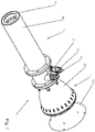
- Fig. 3 is a perspective view of the air compressor assembly of Fig. 1 .
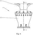
- Fig. 4 is a side view of the air compressor assembly of Fig. 3 .
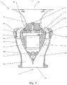
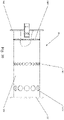
- Fig. 5 is a cross-section view taken along the line A-A of the air compressor assembly of Fig. 4 .
- Fig. 6 is a bottom view of the air compressor assembly of Fig. 3 .
- the air compressor assembly 2 includes an inlet opening 20, an outlet opening 21, a body 22, a motor 23, and a propeller 24.
- the inlet opening 20 is used for inhaling air into the burning apparatus 1, and the outlet opening 21 is used for communicating with the combustion assembly 3.
- the motor 23 includes a motor shaft 230 and is disposed in the body 22. The motor 23 drives the propeller 24 through the motor shaft 230.
- the inlet opening 20 may be configured to be any shape for guiding air into the inlet opening 20 of the air compressor assembly 2 and therefore into the body 22.
- the body 22 is axially disposed along the axis P.
- the body 22 comprises an outer housing 220, an inner housing 221, and an air passage 222.
- the inner housing 221 is disposed in the outer housing 220 and is connected to the outer housing 220 of the body 22.
- the motor 23 is disposed in the inner housing 221 of the body 22.
- the inner housing 221 and the outer housing 220 define an air passage 222 therebetween.
- the propeller 24 guides air from the air compressor assembly 2 into the combustion assembly 3 through the air passage 222. Namely, the inlet opening 20, an outlet opening 21, and the air passage 222 allow air to flow therethrough.
- the body 22 of a preferred embodiment also includes a rib 224 or multiple ribs 224 for realizing a more laminar flow motion of air in the air passage 222 and for reinforcing the connection between the outer housing 220 and the inner housing 221.
- the ribs 224 may fully or partially extend between the outer housing 220 and the inner housing 221 in the air passage 222.
- the air compressor assembly 2 further comprises a hood 25 configured for guiding and sucking air into the inlet opening 20 of the air compressor assembly 2.
- the hood 25 is also axially disposed along the axis P and adapted to the propeller 24 to collect and optimize air transmission into the burning apparatus 1.
- the hood 25 is configured to be shaped for optimally guiding the air from the propeller 24 into the air passage 222 of the body 22 of the air compressor assembly 2.
- the air compressor assembly 2 further comprises a plastic mounting plate 26 and a metal mounting plate 27.
- the plastic mounting plate 26 and the metal mounting plate 27 include openings to let air go into the air passage 222 of the air compressor assembly 2.
- the plastic mounting plate 26 is for receiving the propeller 24 and disposed between the hood 25, the metal mounting plate 27, and the body 22.
- the plastic mounting plate 26 includes a propeller guiding feature to realize a more laminar flow of the air.
- the metal mounting plate 27 is disposed between the plastic mounting plate 26 and the body 22.
- Several screws 28 are used for the connection between the plastic mounting plate 26, the metal mounting plate 27, the hood 25, and the body 22 of the air compressor assembly 2, improving the stability of the air compressor assembly 2.
- the body 22 of the air compressor assembly 2 can be constructed as integral, and the hood 25 and the body 22 can be constructed as integral.
- the air compressor assembly 2 and the combustion assembly 3 can be constructed as integral.
- a motor of a conventional burning apparatus 1 usually has a problem in heat dissipation when the motor works.
- the burning apparatus 1 is designed to have a cooling feature.
- the inner housing 221 of the body 22 includes an inner housing opening 2210 which allows air to flow from the air passage 222 into the inner housing 221 for cooling the motor 23. So, the air in the air compressor assembly 2 is fully circulated.
- the inner housing 221 also includes a cavity 2211 for optimizing the flow path of the cooling air.
- the body 22 includes a wire channel 223 passing through the outer housing 220 and the inner housing 221 to receive a wire of the motor 23 and/or to release the cooling air which also cools down the wire of motors 23 accordingly. The wire channel 223 and the cavity 2211 are communicated.
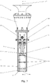
- Fig. 7 is a partial cross-section view taken along the line A-A of the burning apparatus of Fig. 2 .
- Fig. 8 is a cross-section view taken along the line A-A of the burning apparatus of Fig. 7 .
- Fig. 9 is a perspective view of the burning tube assembly of the combustion assembly of the burning apparatus of Fig. 1 .
- Fig. 10 is a side view of the burning tube assembly of Fig. 9 .
- Fig. 11 is a perspective view of the burning tube assembly of Fig. 10 .
- Fig. 12 is another perspective view of the burning tube assembly of Fig. 10 .
- Fig. 13 is a cross-section view taken along the line A-A of the burning apparatus of Fig. 7 , showing the airflow.
- the combustion assembly 3 includes a combustion assembly housing 30, a fuel means 31, an ignition means 32, and a burning tube assembly 33.
- the combustion assembly housing 30 may be configured to be a tube and is connected to the air compressor assembly 2.
- the combustion assembly housing 30 also includes an inlet opening 300 and an outlet opening 301.
- the inlet opening 300 of the combustion assembly housing 30 communicates with the outlet opening 21 of the air compressor assembly 2, so air can be blown into the combustion assembly 3.
- the fuel means 31 is for providing fuel into the combustion assembly 3.
- the fuel can be any flammable fuel, gas, or liquid for combustion, such as propane, butane, or hydrogen.
- a fuel providing device 4 can be arranged for storing fuel and be connected to the fuel means 31 by a hose (not shown in the drawings).
- the fuel providing device 4 can be a fuel tank or a gas cylinder.
- the ignition means 32 is for igniting the fuel and is connected to an external electrical device 5.
- the external electrical device 5 can be an electrical generator or a power source providing a desired voltage.
- combustion takes place in a burning tube assembly 33.
- the burning tube assembly 33 is disposed in the combustion assembly housing 30 of the combustion assembly 3, and is preferably near the lower part of the combustion assembly housing 30 of the combustion assembly 3.
- the burning tube assembly 33 includes a burning tube body 332, an inlet disc 330, and an outlet disc 331. The detail of the burning tube assembly 33 is provided as follows.
- the burning tube body 332 is configured to be hollow, and is disposed along the axis P and in the combustion assembly housing 30 and between the inlet disc 330 and the outlet disc 331.
- the burning tube assembly 33 is preferably located near the bottom of the combustion assembly housing 30 of the combustion assembly 3.
- the burning tube body 332 and the combustion assembly housing 30 define an air channel 34 therebetween.
- the burning tube body 332 further includes openings 333 designed along the burning tube body 332 to control the amount of air entering from the air channel 34 into the burning tube body 332.
- the inlet disc 330 contains holes for receiving the fuel means 31 and the ignition means 32. Additionally, the inlet disc 330 contains openings 3300 to allow air to enter the air channel 34.
- the outlet disc 331 is formed as a circular disc for sealing the bottom of the air channel 34, while the outlet disc 331 leaves the bottom of the burning tube body 332 open, so a flame F ejects out of the burning apparatus 1.
- the air passage 222 of the air compressor assembly 2, the openings 3300 of the inlet disc 330, the air channel 34 of the combustion assembly 3, the openings 333 of the burning tube body 332, and the outlet opening 301 of the combustion assembly 3 are designed to be communicated for the airflow G (please see the airflow G of Fig. 13 ).
- the fuel means 31 and the ignition means 32 extend into the burning tube body 332 through the holes of the inlet disc 330. Hence, the fuel is provided in the burning tube body 332, and the combustion of the mixture of the fuel and oxygen ignited by the ignition means 32 happens in the burning tube body 332.
- the fuel means 31 may be a fuel tube for transmitting fuel
- the ignition means 32 may be an ignition electrode.
- the fuel means 31 and the ignition means 32 may extend from the outside of the burning tube assembly 33 into the burning tube body 332 and fixed at the inlet disc 330, so the fuel means 31 and the ignition means 32 can limit the reaction of the combustion in the burning tube body 332.
- the fuel means 31 and the ignition means 32 may be included in the air compressor assembly 2.
- the openings 333 of the burning tube body 332 closer to the inlet disc 330 may be designed to be smaller than the openings 333 of the burning tube body 332 closer to the outlet disc 331.
- the openings 333 of the burning tube body 332 can be the first set openings 3331, the second set openings 3332, and the third set openings 3333.
- the first set openings 3331 are located near the inlet disc 330; the third set openings 3333 near the outlet disc 331; the second set openings 3332 are at somewhere between the first set openings 3331 and the third set openings 3333.
- the first set openings 3331 near the inlet disc 330 are smaller than the third set openings 3333 near the outlet disc 331.
- the smaller first set openings 3331 limit the amount of air entering the first set openings 3331 and allow more air flowing in the air channel 34 down to the third set openings 3333 along the burning tube body 332, so that air can cool down the burning tube body 332 as well as the combustion assembly housing 30.
- the size of the smaller first set openings 3331 allows more converged air to enter the burning tube body 332. This can stabilize the formation of a converged flame F in the burning tube body 332.
- the flame F formed near the inlet disc 330 is preferably to be stable and converged.
- the combustion of fuel needs merely a small amount of oxygen, so the smaller first set openings 3331 can maintain the small amount of air and oxygen entering the burning tube assembly 33 to achieve the desired amount and shape of a flame.
- a preferred flame is slim and thin.
- the bigger third set openings 3333 at the outlet disc 331 help blowing the combusted flame F out of the outlet end of the burning tube assembly 33.
- the second set opening 3332 and the third set openings 3333 allow more oxygen to enter the burning tube body 332, ensuring a better mixing of the fuel and oxygen and pushing the flame F from the burning tube body 332 towards the axis P and thus towards the outlet opening 301.
- the burning tube assembly 33 leads to minimal contact of the flame F with the burning tube body 332, so the burning apparatus 1 and the combustion assembly 3 are cooled down during the operation of the burning apparatus 1.
- the combustion assembly 3 includes a sensor 35 for monitoring and detecting the formation of flame F.
- a welding operator may operate the burning apparatus 1 together with the sensor 35 with the following steps: (A) activate the air compressor assembly 2, (B) activate the ignition means 32, (C) provide fuel by the fuel means 31, and (D) detect the presence of the flame F by the sensor 35. If there is no flame detected by the sensor 35, a welding operator checks or restarts the burning apparatus 1 to ensure the safe operation.
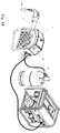
- FIG. 14 is a perspective view of the preheating device equipped with the burning apparatus of Fig. 1 .
- a preheating device 6 for heating molds for railway repair comprises a preheating device body 60 and the burning apparatus 1.
- the burning apparatus 1 is disposed in the preheating device body 60 with the axis P aligning with the railway tracks. So, a welding operator can operate the preheating device 6 to heat the railway tracks.
Landscapes
- Engineering & Computer Science (AREA)
- Mechanical Engineering (AREA)
- Chemical & Material Sciences (AREA)
- Combustion & Propulsion (AREA)
- General Engineering & Computer Science (AREA)
- Architecture (AREA)
- Civil Engineering (AREA)
- Structural Engineering (AREA)
- Physics & Mathematics (AREA)
- Optics & Photonics (AREA)
- Structures Of Non-Positive Displacement Pumps (AREA)
- Machines For Laying And Maintaining Railways (AREA)
Abstract
Description
- The present invention relates to a burning apparatus for railway repair, more particularly for aluminothermic welding.
- At the end of the nineteenth century, aluminothermic welding was invented to weld rail tracks with the development of the metallurgical and chemical industries. To prepare aluminothermic welding for connecting two rail ends, a welding operator should heat the end faces of these rail ends opposite each other in the welding gap. This heating process aims to remove any moisture that may exist in a welding mold. Furthermore, increasing the temperature of the rail ends can slow down the cooling of the heated weld. In this way, a welding operator can obtain a desired certain metallic structure in the welding gap. However, when working at the railway tracks, a welding operator takes much effort and energy to move a conventional preheating burner equipped with an air compressor on and off the railway tracks. The conventional preheating burner is comparatively huge and heavy because the air compressor is usually disposed on the side of the preheating burner. Thus, a conventional preheating burner does not provide a thinner and lighter burning apparatus for railway repair.
- The objective of the present invention is to provide a burning apparatus for railway repair, and more particularly a burning apparatus that provides a thinner and lighter burning apparatus for railway repair.
- The following summarizes some aspects of the present invention to provide a basic understanding of the technology discussed. This summary is not an extensive overview of all contemplated features of the invention, and is intended neither to identify key or critical elements of all aspects of the invention nor to delineate the scope of any or all aspects of the invention. Its sole purpose is to present some concepts of one or more aspects of the invention in a summary form as a prelude to the more detailed description that is presented later.
- A first aspect of the present invention provides a burning apparatus for railway repair, defining an axis and comprising: an air compressor assembly including an inlet opening and an outlet opening, and a combustion assembly connected to the outlet opening of the air compressor assembly, wherein the air compressor assembly and the combustion assembly are axially disposed along the axis, and wherein the air compressor assembly compresses air into the combustion assembly.
- In a second aspect of the present invention according to the first aspect, wherein the air compressor assembly further comprises: a body axially disposed along the axis, a motor including a motor shaft and disposed in the body, and a propeller driven by the motor through the motor shaft and guiding air into the body.
- In a third aspect of the present invention according to the second aspect, wherein the body comprises: an outer housing, and an inner housing disposed in the outer housing and connected to the outer housing, the motor disposed therein, wherein the inner housing and the outer housing defining an air passage therebetween, and the propeller guides air from the air compressor assembly into the combustion assembly through the air passage.
- In a fourth aspect of the present invention according to the third aspect, wherein the body further includes a rib connecting between the outer housing and the inner housing in the air passage.
- In a fifth aspect of the present invention according to any one of the first to fourth aspects, wherein the air compressor assembly further comprises a hood configured for guiding air into the inlet opening of the air compressor assembly.
- In a sixth aspect of the present invention according to any one of the first to fourth aspects, wherein the air compressor assembly further comprises: a plastic mounting plate receiving the propeller and disposed between the hood and the body, and a metal mounting plate disposed between the plastic mounting plate and the body to strengthen the air compressor assembly.
- In a seventh aspect of the present invention according to any one of the third and fourth aspects, wherein the inner housing of the body includes an inner housing opening which allows air to flow from the air passage into the inner housing for cooling the motor.
- In an eighth aspect of the present invention according to any one of the first to fourth aspects, wherein the combustion assembly includes: a combustion assembly housing including an inlet opening and an outlet opening, the inlet opening of the combustion assembly housing communicating with the outlet opening of the air compressor assembly, a fuel means for providing fuel into the combustion assembly, and an ignition means for igniting fuel, wherein the ignition means ignites the fuel in the combustion assembly to produce a flame.
- In a ninth aspect of the present invention according to the eighth aspect, wherein the combustion assembly further includes a burning tube assembly disposed in the combustion assembly housing, the burning tube assembly comprising: an inlet disc, an outlet disc, and a burning tube body configured to be hollow and disposed along the axis in the combustion assembly housing and between the inlet disc and the outlet disc, wherein the burning tube body and the combustion assembly housing define an air channel therebetween, and wherein the air passage of the air compressor assembly, the air channel of the combustion assembly, the burning tube body, and the outlet opening of the combustion assembly are designed to be communicated.
- In a tenth aspect of the present invention according to the ninth aspect, wherein the burning tube body includes openings designed along the burning tube body to control the amount of air entering from the air channel into the burning tube body, wherein the combustion of the mixture of the fuel and air happens in the burning tube body.
- In an eleventh aspect of the present invention according to the tenth aspect, wherein the openings of the burning tube body closer to the inlet disc are designed to be smaller than the openings of the burning tube body closer to the outlet disc.
- In a twelfth aspect of the present invention according to the eighth aspect, wherein the combustion assembly includes a sensor for monitoring and detecting the presence of flame.
- In a thirteen aspect of the present invention according to the eighth aspect, wherein the fuel means is connected to a fuel providing device, and the ignition means is connected to an electrical device.
- In a fourteenth aspect of the present invention according to the fifth aspect, wherein the body of the air compressor assembly can be constructed as integral, and the hood and the body can be constructed as integral.
- In a fifteenth aspect of the present invention according to any of the first to fourteenth aspects, wherein the air compressor assembly and the combustion assembly can be constructed as integral.
- A sixteenth aspect of the present invention provides a preheating device for railway repair, comprising: a preheating device body, and the burning apparatus of any of the first to fifteenth aspects disposed in the preheating device, wherein the preheating device can be operated on the railway tracks to heat the railway.
- Advantageously, the present invention aims to provide a thinner and lighter burning apparatus for railway repair and cooling the combustion assembly.
- Further benefits and advantages of the present invention will become apparent after a careful reading of the detailed description with appropriate reference to the accompanying drawings.
-
-
Fig. 1 is a perspective view of a burning apparatus for heating railway tracks in accordance with the preferred embodiment of the present invention. -
Fig. 2 is a side view of the burning apparatus ofFig. 1 . -
Fig. 3 is a perspective view of the air compressor assembly ofFig. 1 . -
Fig. 4 is a side view of the air compressor assembly ofFig. 3 . -
Fig. 5 is a cross-section view taken along the line A-A of the air compressor assembly ofFig. 4 . -
Fig. 6 is a bottom view of the air compressor assembly ofFig. 3 . -
Fig. 7 is a partial cross-section view taken along the line A-A of the burning apparatus ofFig. 2 . -
Fig. 8 is a cross-section view taken along the line A-A of the burning apparatus ofFig. 7 . -
Fig. 9 is a perspective view of the burning tube assembly of the combustion assembly of the burning apparatus ofFig. 1 . -
Fig. 10 is a side view of the burning tube assembly ofFig. 9 . -
Fig. 11 is a perspective view of the burning tube assembly ofFig. 10 . -
Fig. 12 is another perspective view of the burning tube assembly ofFig. 10 . -
Fig. 13 is a cross-section view taken along the line A-A of the burning apparatus ofFig. 7 , showing the airflow. -
Fig. 14 is a perspective view of the preheating device equipped with the burning apparatus ofFig. 1 . -
Fig. 1 is a perspective view of a burning apparatus for heating railway tracks in accordance with the preferred embodiment of the present invention.Fig. 2 is a side view of the burning apparatus ofFig. 1 . - Please refer to
Figs. 1 and2 together. A burningapparatus 1 is provided for railway repair, such as for heating the railway tracks or drying the molds during the aluminothermic welding process. Specifically, theburning apparatus 1 defines a longitudinal axis P and includes anair compressor assembly 2 and acombustion assembly 3. Theair compressor assembly 2 is used for inhaling air and forcing air (with oxygen) into thecombustion assembly 3 of theburning apparatus 1. Thecombustion assembly 3 is used for the reaction of combustion and for producing flames. Theair compressor assembly 2 and thecombustion assembly 3 are axially disposed along the axis P. During operation, theair compressor assembly 2 compresses air with oxygen into thecombustion assembly 3, so thecombustion assembly 3 can ignite the fuel and oxygen and produce a flame for railway repair. In a preferred embodiment, the temperature of a flame may be within the range of 500 and 2400 Celsius degrees for welding railways. The axial arrangement of theair compressor assembly 2 and thecombustion assembly 3 makes the overall burningapparatus 1 thinner, smaller, and more symmetric. Thus, a welding operator can easily handle and operate theburning apparatus 1 at a railway construction site. -
Fig. 3 is a perspective view of the air compressor assembly ofFig. 1 .Fig. 4 is a side view of the air compressor assembly ofFig. 3 .Fig. 5 is a cross-section view taken along the line A-A of the air compressor assembly ofFig. 4 .Fig. 6 is a bottom view of the air compressor assembly ofFig. 3 . - Please refer to
Figs. 1-6 together. Theair compressor assembly 2 includes aninlet opening 20, anoutlet opening 21, abody 22, amotor 23, and apropeller 24. Theinlet opening 20 is used for inhaling air into the burningapparatus 1, and theoutlet opening 21 is used for communicating with thecombustion assembly 3. Themotor 23 includes amotor shaft 230 and is disposed in thebody 22. Themotor 23 drives thepropeller 24 through themotor shaft 230. Theinlet opening 20 may be configured to be any shape for guiding air into the inlet opening 20 of theair compressor assembly 2 and therefore into thebody 22. - The
body 22 is axially disposed along the axis P. Thebody 22 comprises anouter housing 220, aninner housing 221, and an air passage 222. Specifically, theinner housing 221 is disposed in theouter housing 220 and is connected to theouter housing 220 of thebody 22. Themotor 23 is disposed in theinner housing 221 of thebody 22. Theinner housing 221 and theouter housing 220 define an air passage 222 therebetween. Thepropeller 24 guides air from theair compressor assembly 2 into thecombustion assembly 3 through the air passage 222. Namely, theinlet opening 20, anoutlet opening 21, and the air passage 222 allow air to flow therethrough. - To avoid the turbulence of the air in the
burning apparatus 1, thebody 22 of a preferred embodiment also includes arib 224 ormultiple ribs 224 for realizing a more laminar flow motion of air in the air passage 222 and for reinforcing the connection between theouter housing 220 and theinner housing 221. In a preferred embodiment, theribs 224 may fully or partially extend between theouter housing 220 and theinner housing 221 in the air passage 222. - To facilitate the compression and transmission of air into the inlet opening 300 of the
combustion assembly 3, theair compressor assembly 2 further comprises ahood 25 configured for guiding and sucking air into the inlet opening 20 of theair compressor assembly 2. Thehood 25 is also axially disposed along the axis P and adapted to thepropeller 24 to collect and optimize air transmission into the burningapparatus 1. In a preferred embodiment, thehood 25 is configured to be shaped for optimally guiding the air from thepropeller 24 into the air passage 222 of thebody 22 of theair compressor assembly 2. - To strengthen the connection and assembling of the
body 22 and thehood 25, theair compressor assembly 2 further comprises aplastic mounting plate 26 and ametal mounting plate 27. Theplastic mounting plate 26 and themetal mounting plate 27 include openings to let air go into the air passage 222 of theair compressor assembly 2. Theplastic mounting plate 26 is for receiving thepropeller 24 and disposed between thehood 25, themetal mounting plate 27, and thebody 22. In a preferred embodiment, theplastic mounting plate 26 includes a propeller guiding feature to realize a more laminar flow of the air. Themetal mounting plate 27 is disposed between the plastic mountingplate 26 and thebody 22.Several screws 28 are used for the connection between the plastic mountingplate 26, themetal mounting plate 27, thehood 25, and thebody 22 of theair compressor assembly 2, improving the stability of theair compressor assembly 2. In a preferred embodiment, thebody 22 of theair compressor assembly 2 can be constructed as integral, and thehood 25 and thebody 22 can be constructed as integral. In a preferred embodiment, theair compressor assembly 2 and thecombustion assembly 3 can be constructed as integral. - A motor of a
conventional burning apparatus 1 usually has a problem in heat dissipation when the motor works. The burningapparatus 1 is designed to have a cooling feature. Specifically, theinner housing 221 of thebody 22 includes aninner housing opening 2210 which allows air to flow from the air passage 222 into theinner housing 221 for cooling themotor 23. So, the air in theair compressor assembly 2 is fully circulated. In addition, theinner housing 221 also includes acavity 2211 for optimizing the flow path of the cooling air. Also, thebody 22 includes awire channel 223 passing through theouter housing 220 and theinner housing 221 to receive a wire of themotor 23 and/or to release the cooling air which also cools down the wire ofmotors 23 accordingly. Thewire channel 223 and thecavity 2211 are communicated. -
Fig. 7 is a partial cross-section view taken along the line A-A of the burning apparatus ofFig. 2 .Fig. 8 is a cross-section view taken along the line A-A of the burning apparatus ofFig. 7 .Fig. 9 is a perspective view of the burning tube assembly of the combustion assembly of the burning apparatus ofFig. 1 .Fig. 10 is a side view of the burning tube assembly ofFig. 9 .Fig. 11 is a perspective view of the burning tube assembly ofFig. 10 .Fig. 12 is another perspective view of the burning tube assembly ofFig. 10 .Fig. 13 is a cross-section view taken along the line A-A of the burning apparatus ofFig. 7 , showing the airflow. - Please refer to
Figs. 1-13 together. Thecombustion assembly 3 includes acombustion assembly housing 30, a fuel means 31, an ignition means 32, and a burningtube assembly 33. Thecombustion assembly housing 30 may be configured to be a tube and is connected to theair compressor assembly 2. Thecombustion assembly housing 30 also includes aninlet opening 300 and anoutlet opening 301. Theinlet opening 300 of thecombustion assembly housing 30 communicates with the outlet opening 21 of theair compressor assembly 2, so air can be blown into thecombustion assembly 3. The fuel means 31 is for providing fuel into thecombustion assembly 3. The fuel can be any flammable fuel, gas, or liquid for combustion, such as propane, butane, or hydrogen. Afuel providing device 4 can be arranged for storing fuel and be connected to the fuel means 31 by a hose (not shown in the drawings). For example, thefuel providing device 4 can be a fuel tank or a gas cylinder. Similarly, the ignition means 32 is for igniting the fuel and is connected to an external electrical device 5. For example, the external electrical device 5 can be an electrical generator or a power source providing a desired voltage. When the ignition means 32 ignites the fuel in thecombustion assembly 3 to produce a flame F, theair compressor assembly 2 blows the flame F out of the outlet opening 301 of thecombustion assembly 3. - In another preferred embodiment, combustion takes place in a burning
tube assembly 33. The burningtube assembly 33 is disposed in thecombustion assembly housing 30 of thecombustion assembly 3, and is preferably near the lower part of thecombustion assembly housing 30 of thecombustion assembly 3. Specifically, the burningtube assembly 33 includes a burningtube body 332, aninlet disc 330, and anoutlet disc 331. The detail of the burningtube assembly 33 is provided as follows. - The burning
tube body 332 is configured to be hollow, and is disposed along the axis P and in thecombustion assembly housing 30 and between theinlet disc 330 and theoutlet disc 331. The burningtube assembly 33 is preferably located near the bottom of thecombustion assembly housing 30 of thecombustion assembly 3. The burningtube body 332 and thecombustion assembly housing 30 define anair channel 34 therebetween. In a preferred embodiment, the burningtube body 332 further includesopenings 333 designed along the burningtube body 332 to control the amount of air entering from theair channel 34 into the burningtube body 332. Theinlet disc 330 contains holes for receiving the fuel means 31 and the ignition means 32. Additionally, theinlet disc 330 contains openings 3300 to allow air to enter theair channel 34. So, the air flowed from theair compressor assembly 2 into theair channel 34 of thecombustion assembly 3 via the openings 3300 of theinlet disc 330. On the other hand, theoutlet disc 331 is formed as a circular disc for sealing the bottom of theair channel 34, while theoutlet disc 331 leaves the bottom of the burningtube body 332 open, so a flame F ejects out of theburning apparatus 1. As a result, the air passage 222 of theair compressor assembly 2, the openings 3300 of theinlet disc 330, theair channel 34 of thecombustion assembly 3, theopenings 333 of the burningtube body 332, and the outlet opening 301 of thecombustion assembly 3 are designed to be communicated for the airflow G (please see the airflow G ofFig. 13 ). - The fuel means 31 and the ignition means 32 extend into the burning
tube body 332 through the holes of theinlet disc 330. Hence, the fuel is provided in the burningtube body 332, and the combustion of the mixture of the fuel and oxygen ignited by the ignition means 32 happens in the burningtube body 332. In a preferred embodiment, the fuel means 31 may be a fuel tube for transmitting fuel, and the ignition means 32 may be an ignition electrode. The fuel means 31 and the ignition means 32 may extend from the outside of the burningtube assembly 33 into the burningtube body 332 and fixed at theinlet disc 330, so the fuel means 31 and the ignition means 32 can limit the reaction of the combustion in the burningtube body 332. In another preferred embodiment, the fuel means 31 and the ignition means 32 may be included in theair compressor assembly 2. - To further optimize the cooling effect of the burning
tube assembly 33 and improve the efficiency of the combustion, theopenings 333 of the burningtube body 332 closer to theinlet disc 330 may be designed to be smaller than theopenings 333 of the burningtube body 332 closer to theoutlet disc 331. For example, theopenings 333 of the burningtube body 332 can be thefirst set openings 3331, thesecond set openings 3332, and thethird set openings 3333. Thefirst set openings 3331 are located near theinlet disc 330; thethird set openings 3333 near theoutlet disc 331; thesecond set openings 3332 are at somewhere between thefirst set openings 3331 and thethird set openings 3333. Namely, thefirst set openings 3331 near theinlet disc 330 are smaller than thethird set openings 3333 near theoutlet disc 331. This leads to the following benefits. First, the smallerfirst set openings 3331 limit the amount of air entering thefirst set openings 3331 and allow more air flowing in theair channel 34 down to thethird set openings 3333 along the burningtube body 332, so that air can cool down the burningtube body 332 as well as thecombustion assembly housing 30. Second, the size of the smallerfirst set openings 3331 allows more converged air to enter the burningtube body 332. This can stabilize the formation of a converged flame F in the burningtube body 332. The flame F formed near theinlet disc 330 is preferably to be stable and converged. Third, the combustion of fuel needs merely a small amount of oxygen, so the smallerfirst set openings 3331 can maintain the small amount of air and oxygen entering the burningtube assembly 33 to achieve the desired amount and shape of a flame. A preferred flame is slim and thin. Fourth, the biggerthird set openings 3333 at theoutlet disc 331 help blowing the combusted flame F out of the outlet end of the burningtube assembly 33. The second set opening 3332 and thethird set openings 3333 allow more oxygen to enter the burningtube body 332, ensuring a better mixing of the fuel and oxygen and pushing the flame F from the burningtube body 332 towards the axis P and thus towards theoutlet opening 301. The burningtube assembly 33 leads to minimal contact of the flame F with the burningtube body 332, so theburning apparatus 1 and thecombustion assembly 3 are cooled down during the operation of theburning apparatus 1. - To ensure the safety of the combustion, the
combustion assembly 3 includes asensor 35 for monitoring and detecting the formation of flame F. Specifically, a welding operator may operate theburning apparatus 1 together with thesensor 35 with the following steps: (A) activate theair compressor assembly 2, (B) activate the ignition means 32, (C) provide fuel by the fuel means 31, and (D) detect the presence of the flame F by thesensor 35. If there is no flame detected by thesensor 35, a welding operator checks or restarts the burningapparatus 1 to ensure the safe operation. -
Fig. 14 is a perspective view of the preheating device equipped with the burning apparatus ofFig. 1 . A preheating device 6 for heating molds for railway repair comprises apreheating device body 60 and theburning apparatus 1. The burningapparatus 1 is disposed in thepreheating device body 60 with the axis P aligning with the railway tracks. So, a welding operator can operate the preheating device 6 to heat the railway tracks. - Although the invention has been explained in relation to its preferred embodiment(s) as mentioned above, it is to be understood that many other possible modifications and variations can be made without departing from the scope of the present invention. It is, therefore, contemplated that the appended claim or claims will cover such modifications and variations that fall within the true scope of the invention.
-
- 1
- burning apparatus
- 2
- air compressor assembly
- 20
- inlet opening
- 21
- outlet opening
- 22
- body
- 220
- outer housing
- 221
- inner housing
- 2210
- inner housing opening
- 2211
- cavity
- 222
- air passage
- 223
- wire channel
- 224
- rib
- 23
- motor
- 230
- motor shaft
- 24
- propeller
- 25
- hood
- 26
- plastic mounting plate
- 27
- metal mounting plate
- 28
- screw
- 3
- combustion assembly
- 30
- combustion assembly housing
- 300
- inlet opening
- 301
- outlet opening
- 31
- fuel means
- 32
- ignition means
- 33
- burning tube assembly
- 330
- inlet disc
- 3300
- openings of the inlet disc
- 331
- outlet disc
- 332
- burning tube body
- 333
- openings
- 3331
- first set openings
- 3332
- second set openings
- 3333
- third set openings
- 34
- air channel
- 35
- sensor
- 4
- fuel providing device
- 5
- electrical device
- 6
- preheating device
- 60
- preheating device body
- F
- flame
- P
- axis
- G
- airflow
Claims (16)
- A burning apparatus for railway repair, defining an axis (P) and comprising:an air compressor assembly (2) including an inlet opening (20) and an outlet opening (21), anda combustion assembly (3) connected to the outlet opening (301) of the air compressor assembly (2),wherein the air compressor assembly (2) and the combustion assembly (3) are axially disposed along the axis (P), and wherein the air compressor assembly (2) compresses air into the combustion assembly (3).
- The burning apparatus of Claim 1, wherein the air compressor assembly (2) further comprises:a body (22) axially disposed along the axis (P),a motor (23) including a motor shaft (230) and disposed in the body (22), anda propeller (24) driven by the motor (23) through the motor shaft (230) and guiding air into the body (22).
- The burning apparatus of Claim 2, wherein the body (22) comprises:an outer housing (220), andan inner housing (221) disposed in the outer housing (220) and connected to the outer housing (220), the motor (23) disposed therein,wherein the inner housing (221) and the outer housing (220) defining an air passage (222) therebetween, and the propeller (24) guides air from the air compressor assembly (2) into the combustion assembly (3) through the air passage (222).
- The burning apparatus of Claim 3, wherein the body (22) further includes a rib (224) connecting between the outer housing (220) and the inner housing (221) in the air passage (222).
- The burning apparatus of any one of Claims 1-4, wherein the air compressor assembly (2) further comprises a hood (25) configured for guiding air into the inlet opening (20) of the air compressor assembly (2).
- The burning apparatus of any one of Claims 1-4, wherein the air compressor assembly (2) further comprises:a plastic mounting plate (26) receiving the propeller (24) and disposed between the hood (25) and the body (22), anda metal mounting plate (27) disposed between the plastic mounting plate (26) and the body (22) to strengthen the air compressor assembly (2).
- The burning apparatus of any one of Claims 3 and 4, wherein the inner housing (221) of the body (22) includes an inner housing opening (2210) which allows air to flow from the air passage (222) into the inner housing (221) for cooling the motor (23).
- The burning apparatus of any one of Claims 1-4, wherein the combustion assembly (3) includes:a combustion assembly housing (30) including an inlet opening (300) and an outlet opening (301), the inlet opening (300) of the combustion assembly housing (30) communicating with the outlet opening (21) of the air compressor assembly (2),a fuel means (31) for providing fuel into the combustion assembly (3), andan ignition means (32) for igniting fuel,wherein the ignition means (32) ignites the fuel in the combustion assembly (3) to produce a flame (F).
- The burning apparatus of Claim 8, wherein the combustion assembly (3) further includes a burning tube assembly (33) disposed in the combustion assembly housing (30), the burning tube assembly (33) comprising:an inlet disc (330),an outlet disc (331), anda burning tube body (332) configured to be hollow and disposed along the axis (P) in the combustion assembly housing (30) and between the inlet disc (330) and the outlet disc (331),wherein the burning tube body (332) and the combustion assembly housing (30) define an air channel (34) therebetween, andwherein the air passage (222) of the air compressor assembly (2), the air channel (34) of the combustion assembly (3), the burning tube body (332), and the outlet opening (301) of the combustion assembly (3) are designed to be communicated.
- The burning apparatus of Claim 9, wherein the burning tube body (332) includes openings (333) designed along the burning tube body (332) to control the amount of air entering from the air channel (34) into the burning tube body (332), wherein the combustion of the mixture of the fuel and air happens in the burning tube body (332).
- The burning apparatus of Claim 10, wherein the openings (333, 3331) of the burning tube body (332) closer to the inlet disc (330) are designed to be smaller than the openings (333, 3333) of the burning tube body (332) closer to the outlet disc (331).
- The burning apparatus of Claim 8, wherein the combustion assembly (3) includes a sensor (35) for monitoring and detecting the presence of flame (F).
- The burning apparatus of Claim 8, wherein the fuel means (31) is connected to a fuel providing device (4), and the ignition means (32) is connected to an electrical device (5).
- The burning apparatus of Claim 5, wherein the body (22) of the air compressor assembly (2) can be constructed as integral, and the hood (25) and the body (22) can be constructed as integral.
- The burning apparatus of any one of Claims 1-14, wherein the air compressor assembly (2) and the combustion assembly (3) can be constructed as integral.
- A preheating device for railway repair, comprising:a preheating device body (60), andthe burning apparatus (1) of any of Claims 1-15 disposed in the preheating device,wherein the preheating device (6) can be operated on the railway tracks to heat the railway.
Priority Applications (5)
| Application Number | Priority Date | Filing Date | Title |
|---|---|---|---|
| EP20205851.7A EP3995739B1 (en) | 2020-11-05 | 2020-11-05 | Burning apparatus for railway repair |
| US18/251,308 US12358072B2 (en) | 2020-11-05 | 2021-10-27 | Burning apparatus for railway repair |
| PCT/EP2021/079864 WO2022096346A1 (en) | 2020-11-05 | 2021-10-27 | Burning apparatus for railway repair |
| AU2021374765A AU2021374765A1 (en) | 2020-11-05 | 2021-10-27 | Burning apparatus for railway repair |
| CN202180074162.8A CN116457134B (en) | 2020-11-05 | 2021-10-27 | Combustion device for railway maintenance |
Applications Claiming Priority (1)
| Application Number | Priority Date | Filing Date | Title |
|---|---|---|---|
| EP20205851.7A EP3995739B1 (en) | 2020-11-05 | 2020-11-05 | Burning apparatus for railway repair |
Publications (3)
| Publication Number | Publication Date |
|---|---|
| EP3995739A1 true EP3995739A1 (en) | 2022-05-11 |
| EP3995739C0 EP3995739C0 (en) | 2025-07-09 |
| EP3995739B1 EP3995739B1 (en) | 2025-07-09 |
Family
ID=73288363
Family Applications (1)
| Application Number | Title | Priority Date | Filing Date |
|---|---|---|---|
| EP20205851.7A Active EP3995739B1 (en) | 2020-11-05 | 2020-11-05 | Burning apparatus for railway repair |
Country Status (5)
| Country | Link |
|---|---|
| US (1) | US12358072B2 (en) |
| EP (1) | EP3995739B1 (en) |
| CN (1) | CN116457134B (en) |
| AU (1) | AU2021374765A1 (en) |
| WO (1) | WO2022096346A1 (en) |
Citations (3)
| Publication number | Priority date | Publication date | Assignee | Title |
|---|---|---|---|---|
| DE754458C (en) * | 1943-12-04 | 1953-08-03 | Elektro Thermit Gmbh | Process for increasing the vapor pressure of liquid gases stored in steel cylinders |
| DE202016005661U1 (en) * | 2016-09-15 | 2016-10-04 | Elektro-Thermit Gmbh & Co. Kg | Preheating burner for aluminothermic welding |
| CN109048125A (en) * | 2018-06-29 | 2018-12-21 | 施密特钢轨技术(昆山)有限公司 | A kind of rail aluminum weld Intelligent preheating mechanism |
Family Cites Families (14)
| Publication number | Priority date | Publication date | Assignee | Title |
|---|---|---|---|---|
| FR1425524A (en) * | 1964-12-10 | 1966-01-24 | Preheating unit, in particular for thermite welding | |
| US3894526A (en) * | 1972-10-16 | 1975-07-15 | Eberspaecher J | Space heater construction particularly for mobile installations |
| JPS61250413A (en) * | 1985-04-27 | 1986-11-07 | Nakajima Doukoushiyo:Kk | Hot air generator |
| US5232153A (en) * | 1988-03-11 | 1993-08-03 | J. Eberspacher | Arrangement for the reduction of the exhaust gas temperature in heating devices |
| US4942863A (en) * | 1989-04-06 | 1990-07-24 | John C. Young | Thermoelectric generator for use in a heater and method of installation |
| US6533189B2 (en) * | 1999-12-14 | 2003-03-18 | Vortex Sprayliners, Inc. | Method and apparatus for spraying truck bed liners |
| US6474981B1 (en) * | 2000-09-27 | 2002-11-05 | Emerson Electric Co. | Co-axial furnace blower with simplified construction |
| US6460536B2 (en) * | 2001-02-28 | 2002-10-08 | Matweld, Inc. | Hydraulically powered rail pre-heater |
| US9080773B2 (en) * | 2008-03-27 | 2015-07-14 | Schwank Ltd. | Pitot tube pressure sensor for radiant tube heater |
| US20110183274A1 (en) * | 2008-08-26 | 2011-07-28 | Michael Bahn | Producing ageing gas for exhaust gas after-treatment systems |
| US8201551B1 (en) * | 2009-04-06 | 2012-06-19 | Procom Heating, Inc. | Gas forced air heater |
| US9267704B1 (en) * | 2012-01-26 | 2016-02-23 | Procom Heating, Inc. | Portable heater housing |
| CN205184004U (en) * | 2015-11-30 | 2016-04-27 | 上海沪工焊接集团股份有限公司 | Portable numerical control cutting machine |
| CN109869330A (en) * | 2019-03-28 | 2019-06-11 | 大连海事大学 | A kind of two-stage dynamoelectric compressor |
-
2020
- 2020-11-05 EP EP20205851.7A patent/EP3995739B1/en active Active
-
2021
- 2021-10-27 WO PCT/EP2021/079864 patent/WO2022096346A1/en not_active Ceased
- 2021-10-27 CN CN202180074162.8A patent/CN116457134B/en active Active
- 2021-10-27 US US18/251,308 patent/US12358072B2/en active Active
- 2021-10-27 AU AU2021374765A patent/AU2021374765A1/en active Pending
Patent Citations (3)
| Publication number | Priority date | Publication date | Assignee | Title |
|---|---|---|---|---|
| DE754458C (en) * | 1943-12-04 | 1953-08-03 | Elektro Thermit Gmbh | Process for increasing the vapor pressure of liquid gases stored in steel cylinders |
| DE202016005661U1 (en) * | 2016-09-15 | 2016-10-04 | Elektro-Thermit Gmbh & Co. Kg | Preheating burner for aluminothermic welding |
| CN109048125A (en) * | 2018-06-29 | 2018-12-21 | 施密特钢轨技术(昆山)有限公司 | A kind of rail aluminum weld Intelligent preheating mechanism |
Also Published As
| Publication number | Publication date |
|---|---|
| AU2021374765A9 (en) | 2024-06-13 |
| EP3995739C0 (en) | 2025-07-09 |
| CN116457134A (en) | 2023-07-18 |
| US12358072B2 (en) | 2025-07-15 |
| EP3995739B1 (en) | 2025-07-09 |
| WO2022096346A1 (en) | 2022-05-12 |
| CN116457134B (en) | 2026-02-10 |
| US20240001482A1 (en) | 2024-01-04 |
| AU2021374765A1 (en) | 2023-05-25 |
Similar Documents
| Publication | Publication Date | Title |
|---|---|---|
| KR100705260B1 (en) | Electric cooker | |
| CN110464054B (en) | An electronic cigarette device utilizing spiral airway for heat dissipation | |
| JPS61250413A (en) | Hot air generator | |
| US12358072B2 (en) | Burning apparatus for railway repair | |
| WO2021177307A1 (en) | Blower | |
| CA2608038C (en) | Radiant tube heater assembly | |
| WO2023151725A3 (en) | Air supply mechanism for biomass hot-blast stove | |
| SE512645C2 (en) | Portable burner | |
| CN101384855A (en) | Apparatus for burning organic matter | |
| AU2012247804B2 (en) | Preheating device | |
| CN212566326U (en) | Combustor and gas indirect heating equipment | |
| US6305172B1 (en) | Scroll for a combustion system | |
| JP2003511617A (en) | Gas-operated generator thermal device | |
| CN113915995B (en) | Shuttle type end burning furnace | |
| CN109186079B (en) | A strong extraction type gas water heater | |
| CN221122220U (en) | Novel natural gas cracking furnace burner | |
| KR20240001196A (en) | gas supply device | |
| CN110000455A (en) | Plasma arc cutting torch | |
| CN221375670U (en) | Air duct system, combustion device and gas stove | |
| CN223691352U (en) | Gas-liquid separator and air conditioner | |
| CN120020447A (en) | Air duct system, combustion device and gas stove | |
| CN221527327U (en) | Roasting furnace for efficient graphite production | |
| CN108050854A (en) | Burner gas feeding mechanism and melting holding furnace | |
| CN110341435B (en) | Air blower for combustion | |
| CN118198630A (en) | A thermal management device for a power battery |
Legal Events
| Date | Code | Title | Description |
|---|---|---|---|
| PUAI | Public reference made under article 153(3) epc to a published international application that has entered the european phase |
Free format text: ORIGINAL CODE: 0009012 |
|
| STAA | Information on the status of an ep patent application or granted ep patent |
Free format text: STATUS: THE APPLICATION HAS BEEN PUBLISHED |
|
| AK | Designated contracting states |
Kind code of ref document: A1 Designated state(s): AL AT BE BG CH CY CZ DE DK EE ES FI FR GB GR HR HU IE IS IT LI LT LU LV MC MK MT NL NO PL PT RO RS SE SI SK SM TR |
|
| STAA | Information on the status of an ep patent application or granted ep patent |
Free format text: STATUS: REQUEST FOR EXAMINATION WAS MADE |
|
| 17P | Request for examination filed |
Effective date: 20220922 |
|
| RBV | Designated contracting states (corrected) |
Designated state(s): AL AT BE BG CH CY CZ DE DK EE ES FI FR GB GR HR HU IE IS IT LI LT LU LV MC MK MT NL NO PL PT RO RS SE SI SK SM TR |
|
| STAA | Information on the status of an ep patent application or granted ep patent |
Free format text: STATUS: EXAMINATION IS IN PROGRESS |
|
| 17Q | First examination report despatched |
Effective date: 20230525 |
|
| REG | Reference to a national code |
Ref country code: DE Ref legal event code: R079 Free format text: PREVIOUS MAIN CLASS: F23D0014360000 Ipc: B23K0023000000 Ref country code: DE Ref legal event code: R079 Ref document number: 602020054128 Country of ref document: DE Free format text: PREVIOUS MAIN CLASS: F23D0014360000 Ipc: B23K0023000000 |
|
| GRAP | Despatch of communication of intention to grant a patent |
Free format text: ORIGINAL CODE: EPIDOSNIGR1 |
|
| STAA | Information on the status of an ep patent application or granted ep patent |
Free format text: STATUS: GRANT OF PATENT IS INTENDED |
|
| RIC1 | Information provided on ipc code assigned before grant |
Ipc: F23K 5/00 20060101ALN20231025BHEP Ipc: F23D 14/34 20060101ALI20231025BHEP Ipc: E01B 31/02 20060101ALI20231025BHEP Ipc: F23D 14/40 20060101ALI20231025BHEP Ipc: F23D 99/00 20100101ALI20231025BHEP Ipc: F23D 14/38 20060101ALI20231025BHEP Ipc: E01B 29/44 20060101ALI20231025BHEP Ipc: E01B 11/52 20060101ALI20231025BHEP Ipc: F23D 14/36 20060101ALI20231025BHEP Ipc: B23P 6/00 20060101ALI20231025BHEP Ipc: B23K 37/00 20060101ALI20231025BHEP Ipc: B23K 23/00 20060101AFI20231025BHEP |
|
| INTG | Intention to grant announced |
Effective date: 20231109 |
|
| GRAJ | Information related to disapproval of communication of intention to grant by the applicant or resumption of examination proceedings by the epo deleted |
Free format text: ORIGINAL CODE: EPIDOSDIGR1 |
|
| STAA | Information on the status of an ep patent application or granted ep patent |
Free format text: STATUS: EXAMINATION IS IN PROGRESS |
|
| INTC | Intention to grant announced (deleted) | ||
| GRAS | Grant fee paid |
Free format text: ORIGINAL CODE: EPIDOSNIGR3 |
|
| STAA | Information on the status of an ep patent application or granted ep patent |
Free format text: STATUS: GRANT OF PATENT IS INTENDED |
|
| GRAP | Despatch of communication of intention to grant a patent |
Free format text: ORIGINAL CODE: EPIDOSNIGR1 |
|
| RIC1 | Information provided on ipc code assigned before grant |
Ipc: F23K 5/00 20060101ALN20241203BHEP Ipc: F23D 14/34 20060101ALI20241203BHEP Ipc: E01B 31/02 20060101ALI20241203BHEP Ipc: F23D 14/40 20060101ALI20241203BHEP Ipc: F23D 99/00 20100101ALI20241203BHEP Ipc: F23D 14/38 20060101ALI20241203BHEP Ipc: E01B 29/44 20060101ALI20241203BHEP Ipc: E01B 11/52 20060101ALI20241203BHEP Ipc: F23D 14/36 20060101ALI20241203BHEP Ipc: B23P 6/00 20060101ALI20241203BHEP Ipc: B23K 37/00 20060101ALI20241203BHEP Ipc: B23K 23/00 20060101AFI20241203BHEP |
|
| INTG | Intention to grant announced |
Effective date: 20241218 |
|
| GRAA | (expected) grant |
Free format text: ORIGINAL CODE: 0009210 |
|
| STAA | Information on the status of an ep patent application or granted ep patent |
Free format text: STATUS: THE PATENT HAS BEEN GRANTED |
|
| AK | Designated contracting states |
Kind code of ref document: B1 Designated state(s): AL AT BE BG CH CY CZ DE DK EE ES FI FR GB GR HR HU IE IS IT LI LT LU LV MC MK MT NL NO PL PT RO RS SE SI SK SM TR |
|
| REG | Reference to a national code |
Ref country code: GB Ref legal event code: FG4D |
|
| REG | Reference to a national code |
Ref country code: CH Ref legal event code: EP |
|
| REG | Reference to a national code |
Ref country code: IE Ref legal event code: FG4D |
|
| U01 | Request for unitary effect filed |
Effective date: 20250709 |
|
| U07 | Unitary effect registered |
Designated state(s): AT BE BG DE DK EE FI FR IT LT LU LV MT NL PT RO SE SI Effective date: 20250715 |
|
| U20 | Renewal fee for the european patent with unitary effect paid |
Year of fee payment: 6 Effective date: 20251002 |
|
| PG25 | Lapsed in a contracting state [announced via postgrant information from national office to epo] |
Ref country code: IS Free format text: LAPSE BECAUSE OF FAILURE TO SUBMIT A TRANSLATION OF THE DESCRIPTION OR TO PAY THE FEE WITHIN THE PRESCRIBED TIME-LIMIT Effective date: 20251109 |
|
| PG25 | Lapsed in a contracting state [announced via postgrant information from national office to epo] |
Ref country code: NO Free format text: LAPSE BECAUSE OF FAILURE TO SUBMIT A TRANSLATION OF THE DESCRIPTION OR TO PAY THE FEE WITHIN THE PRESCRIBED TIME-LIMIT Effective date: 20251009 |
|
| PG25 | Lapsed in a contracting state [announced via postgrant information from national office to epo] |
Ref country code: HR Free format text: LAPSE BECAUSE OF FAILURE TO SUBMIT A TRANSLATION OF THE DESCRIPTION OR TO PAY THE FEE WITHIN THE PRESCRIBED TIME-LIMIT Effective date: 20250709 |
|
| PG25 | Lapsed in a contracting state [announced via postgrant information from national office to epo] |
Ref country code: GR Free format text: LAPSE BECAUSE OF FAILURE TO SUBMIT A TRANSLATION OF THE DESCRIPTION OR TO PAY THE FEE WITHIN THE PRESCRIBED TIME-LIMIT Effective date: 20251010 |
|
| PG25 | Lapsed in a contracting state [announced via postgrant information from national office to epo] |
Ref country code: PL Free format text: LAPSE BECAUSE OF FAILURE TO SUBMIT A TRANSLATION OF THE DESCRIPTION OR TO PAY THE FEE WITHIN THE PRESCRIBED TIME-LIMIT Effective date: 20250709 |
|
| PG25 | Lapsed in a contracting state [announced via postgrant information from national office to epo] |
Ref country code: RS Free format text: LAPSE BECAUSE OF FAILURE TO SUBMIT A TRANSLATION OF THE DESCRIPTION OR TO PAY THE FEE WITHIN THE PRESCRIBED TIME-LIMIT Effective date: 20251009 |
|
| PG25 | Lapsed in a contracting state [announced via postgrant information from national office to epo] |
Ref country code: ES Free format text: LAPSE BECAUSE OF FAILURE TO SUBMIT A TRANSLATION OF THE DESCRIPTION OR TO PAY THE FEE WITHIN THE PRESCRIBED TIME-LIMIT Effective date: 20250709 |
|
| PG25 | Lapsed in a contracting state [announced via postgrant information from national office to epo] |
Ref country code: SM Free format text: LAPSE BECAUSE OF FAILURE TO SUBMIT A TRANSLATION OF THE DESCRIPTION OR TO PAY THE FEE WITHIN THE PRESCRIBED TIME-LIMIT Effective date: 20250709 |
|
| PGFP | Annual fee paid to national office [announced via postgrant information from national office to epo] |
Ref country code: GB Payment date: 20260107 Year of fee payment: 6 |
|
| PG25 | Lapsed in a contracting state [announced via postgrant information from national office to epo] |
Ref country code: CZ Free format text: LAPSE BECAUSE OF FAILURE TO SUBMIT A TRANSLATION OF THE DESCRIPTION OR TO PAY THE FEE WITHIN THE PRESCRIBED TIME-LIMIT Effective date: 20250709 |
|
| PG25 | Lapsed in a contracting state [announced via postgrant information from national office to epo] |
Ref country code: SK Free format text: LAPSE BECAUSE OF FAILURE TO SUBMIT A TRANSLATION OF THE DESCRIPTION OR TO PAY THE FEE WITHIN THE PRESCRIBED TIME-LIMIT Effective date: 20250709 |