EP3995686A1 - Thermoplastic acoustic blocker door - Google Patents
Thermoplastic acoustic blocker door Download PDFInfo
- Publication number
- EP3995686A1 EP3995686A1 EP21212294.9A EP21212294A EP3995686A1 EP 3995686 A1 EP3995686 A1 EP 3995686A1 EP 21212294 A EP21212294 A EP 21212294A EP 3995686 A1 EP3995686 A1 EP 3995686A1
- Authority
- EP
- European Patent Office
- Prior art keywords
- sandwich panel
- various embodiments
- plate
- blocker door
- backsheet
- Prior art date
- Legal status (The legal status is an assumption and is not a legal conclusion. Google has not performed a legal analysis and makes no representation as to the accuracy of the status listed.)
- Granted
Links
Images




Classifications
-
- F—MECHANICAL ENGINEERING; LIGHTING; HEATING; WEAPONS; BLASTING
- F02—COMBUSTION ENGINES; HOT-GAS OR COMBUSTION-PRODUCT ENGINE PLANTS
- F02K—JET-PROPULSION PLANTS
- F02K1/00—Plants characterised by the form or arrangement of the jet pipe or nozzle; Jet pipes or nozzles peculiar thereto
- F02K1/54—Nozzles having means for reversing jet thrust
- F02K1/64—Reversing fan flow
- F02K1/70—Reversing fan flow using thrust reverser flaps or doors mounted on the fan housing
- F02K1/72—Reversing fan flow using thrust reverser flaps or doors mounted on the fan housing the aft end of the fan housing being movable to uncover openings in the fan housing for the reversed flow
-
- B—PERFORMING OPERATIONS; TRANSPORTING
- B29—WORKING OF PLASTICS; WORKING OF SUBSTANCES IN A PLASTIC STATE IN GENERAL
- B29C—SHAPING OR JOINING OF PLASTICS; SHAPING OF MATERIAL IN A PLASTIC STATE, NOT OTHERWISE PROVIDED FOR; AFTER-TREATMENT OF THE SHAPED PRODUCTS, e.g. REPAIRING
- B29C43/00—Compression moulding, i.e. applying external pressure to flow the moulding material; Apparatus therefor
- B29C43/02—Compression moulding, i.e. applying external pressure to flow the moulding material; Apparatus therefor of articles of definite length, i.e. discrete articles
- B29C43/021—Compression moulding, i.e. applying external pressure to flow the moulding material; Apparatus therefor of articles of definite length, i.e. discrete articles characterised by the shape of the surface
-
- B—PERFORMING OPERATIONS; TRANSPORTING
- B29—WORKING OF PLASTICS; WORKING OF SUBSTANCES IN A PLASTIC STATE IN GENERAL
- B29C—SHAPING OR JOINING OF PLASTICS; SHAPING OF MATERIAL IN A PLASTIC STATE, NOT OTHERWISE PROVIDED FOR; AFTER-TREATMENT OF THE SHAPED PRODUCTS, e.g. REPAIRING
- B29C43/00—Compression moulding, i.e. applying external pressure to flow the moulding material; Apparatus therefor
- B29C43/32—Component parts, details or accessories; Auxiliary operations
- B29C43/36—Moulds for making articles of definite length, i.e. discrete articles
-
- B—PERFORMING OPERATIONS; TRANSPORTING
- B29—WORKING OF PLASTICS; WORKING OF SUBSTANCES IN A PLASTIC STATE IN GENERAL
- B29C—SHAPING OR JOINING OF PLASTICS; SHAPING OF MATERIAL IN A PLASTIC STATE, NOT OTHERWISE PROVIDED FOR; AFTER-TREATMENT OF THE SHAPED PRODUCTS, e.g. REPAIRING
- B29C66/00—General aspects of processes or apparatus for joining preformed parts
- B29C66/70—General aspects of processes or apparatus for joining preformed parts characterised by the composition, physical properties or the structure of the material of the parts to be joined; Joining with non-plastics material
- B29C66/72—General aspects of processes or apparatus for joining preformed parts characterised by the composition, physical properties or the structure of the material of the parts to be joined; Joining with non-plastics material characterised by the structure of the material of the parts to be joined
- B29C66/725—General aspects of processes or apparatus for joining preformed parts characterised by the composition, physical properties or the structure of the material of the parts to be joined; Joining with non-plastics material characterised by the structure of the material of the parts to be joined being hollow-walled or honeycombs
- B29C66/7254—General aspects of processes or apparatus for joining preformed parts characterised by the composition, physical properties or the structure of the material of the parts to be joined; Joining with non-plastics material characterised by the structure of the material of the parts to be joined being hollow-walled or honeycombs honeycomb structures
-
- B—PERFORMING OPERATIONS; TRANSPORTING
- B29—WORKING OF PLASTICS; WORKING OF SUBSTANCES IN A PLASTIC STATE IN GENERAL
- B29C—SHAPING OR JOINING OF PLASTICS; SHAPING OF MATERIAL IN A PLASTIC STATE, NOT OTHERWISE PROVIDED FOR; AFTER-TREATMENT OF THE SHAPED PRODUCTS, e.g. REPAIRING
- B29C70/00—Shaping composites, i.e. plastics material comprising reinforcements, fillers or preformed parts, e.g. inserts
- B29C70/68—Shaping composites, i.e. plastics material comprising reinforcements, fillers or preformed parts, e.g. inserts by incorporating or moulding on preformed parts, e.g. inserts or layers, e.g. foam blocks
- B29C70/74—Moulding material on a relatively small portion of the preformed part, e.g. outsert moulding
-
- F—MECHANICAL ENGINEERING; LIGHTING; HEATING; WEAPONS; BLASTING
- F02—COMBUSTION ENGINES; HOT-GAS OR COMBUSTION-PRODUCT ENGINE PLANTS
- F02K—JET-PROPULSION PLANTS
- F02K1/00—Plants characterised by the form or arrangement of the jet pipe or nozzle; Jet pipes or nozzles peculiar thereto
- F02K1/54—Nozzles having means for reversing jet thrust
- F02K1/64—Reversing fan flow
- F02K1/70—Reversing fan flow using thrust reverser flaps or doors mounted on the fan housing
-
- F—MECHANICAL ENGINEERING; LIGHTING; HEATING; WEAPONS; BLASTING
- F02—COMBUSTION ENGINES; HOT-GAS OR COMBUSTION-PRODUCT ENGINE PLANTS
- F02K—JET-PROPULSION PLANTS
- F02K1/00—Plants characterised by the form or arrangement of the jet pipe or nozzle; Jet pipes or nozzles peculiar thereto
- F02K1/54—Nozzles having means for reversing jet thrust
- F02K1/76—Control or regulation of thrust reversers
- F02K1/763—Control or regulation of thrust reversers with actuating systems or actuating devices; Arrangement of actuators for thrust reversers
-
- B—PERFORMING OPERATIONS; TRANSPORTING
- B29—WORKING OF PLASTICS; WORKING OF SUBSTANCES IN A PLASTIC STATE IN GENERAL
- B29C—SHAPING OR JOINING OF PLASTICS; SHAPING OF MATERIAL IN A PLASTIC STATE, NOT OTHERWISE PROVIDED FOR; AFTER-TREATMENT OF THE SHAPED PRODUCTS, e.g. REPAIRING
- B29C43/00—Compression moulding, i.e. applying external pressure to flow the moulding material; Apparatus therefor
- B29C43/32—Component parts, details or accessories; Auxiliary operations
- B29C43/36—Moulds for making articles of definite length, i.e. discrete articles
- B29C2043/366—Moulds for making articles of definite length, i.e. discrete articles plates pressurized by an actuator, e.g. ram drive, screw, vulcanizing presses
-
- B—PERFORMING OPERATIONS; TRANSPORTING
- B29—WORKING OF PLASTICS; WORKING OF SUBSTANCES IN A PLASTIC STATE IN GENERAL
- B29C—SHAPING OR JOINING OF PLASTICS; SHAPING OF MATERIAL IN A PLASTIC STATE, NOT OTHERWISE PROVIDED FOR; AFTER-TREATMENT OF THE SHAPED PRODUCTS, e.g. REPAIRING
- B29C43/00—Compression moulding, i.e. applying external pressure to flow the moulding material; Apparatus therefor
- B29C43/32—Component parts, details or accessories; Auxiliary operations
- B29C43/36—Moulds for making articles of definite length, i.e. discrete articles
- B29C2043/3665—Moulds for making articles of definite length, i.e. discrete articles cores or inserts, e.g. pins, mandrels, sliders
-
- B—PERFORMING OPERATIONS; TRANSPORTING
- B29—WORKING OF PLASTICS; WORKING OF SUBSTANCES IN A PLASTIC STATE IN GENERAL
- B29C—SHAPING OR JOINING OF PLASTICS; SHAPING OF MATERIAL IN A PLASTIC STATE, NOT OTHERWISE PROVIDED FOR; AFTER-TREATMENT OF THE SHAPED PRODUCTS, e.g. REPAIRING
- B29C65/00—Joining or sealing of preformed parts, e.g. welding of plastics materials; Apparatus therefor
- B29C65/02—Joining or sealing of preformed parts, e.g. welding of plastics materials; Apparatus therefor by heating, with or without pressure
- B29C65/08—Joining or sealing of preformed parts, e.g. welding of plastics materials; Apparatus therefor by heating, with or without pressure using ultrasonic vibrations
-
- B—PERFORMING OPERATIONS; TRANSPORTING
- B29—WORKING OF PLASTICS; WORKING OF SUBSTANCES IN A PLASTIC STATE IN GENERAL
- B29C—SHAPING OR JOINING OF PLASTICS; SHAPING OF MATERIAL IN A PLASTIC STATE, NOT OTHERWISE PROVIDED FOR; AFTER-TREATMENT OF THE SHAPED PRODUCTS, e.g. REPAIRING
- B29C66/00—General aspects of processes or apparatus for joining preformed parts
- B29C66/50—General aspects of joining tubular articles; General aspects of joining long products, i.e. bars or profiled elements; General aspects of joining single elements to tubular articles, hollow articles or bars; General aspects of joining several hollow-preforms to form hollow or tubular articles
- B29C66/51—Joining tubular articles, profiled elements or bars; Joining single elements to tubular articles, hollow articles or bars; Joining several hollow-preforms to form hollow or tubular articles
- B29C66/53—Joining single elements to tubular articles, hollow articles or bars
-
- B—PERFORMING OPERATIONS; TRANSPORTING
- B29—WORKING OF PLASTICS; WORKING OF SUBSTANCES IN A PLASTIC STATE IN GENERAL
- B29C—SHAPING OR JOINING OF PLASTICS; SHAPING OF MATERIAL IN A PLASTIC STATE, NOT OTHERWISE PROVIDED FOR; AFTER-TREATMENT OF THE SHAPED PRODUCTS, e.g. REPAIRING
- B29C66/00—General aspects of processes or apparatus for joining preformed parts
- B29C66/70—General aspects of processes or apparatus for joining preformed parts characterised by the composition, physical properties or the structure of the material of the parts to be joined; Joining with non-plastics material
- B29C66/72—General aspects of processes or apparatus for joining preformed parts characterised by the composition, physical properties or the structure of the material of the parts to be joined; Joining with non-plastics material characterised by the structure of the material of the parts to be joined
- B29C66/721—Fibre-reinforced materials
- B29C66/7214—Fibre-reinforced materials characterised by the length of the fibres
- B29C66/72141—Fibres of continuous length
-
- B—PERFORMING OPERATIONS; TRANSPORTING
- B29—WORKING OF PLASTICS; WORKING OF SUBSTANCES IN A PLASTIC STATE IN GENERAL
- B29C—SHAPING OR JOINING OF PLASTICS; SHAPING OF MATERIAL IN A PLASTIC STATE, NOT OTHERWISE PROVIDED FOR; AFTER-TREATMENT OF THE SHAPED PRODUCTS, e.g. REPAIRING
- B29C66/00—General aspects of processes or apparatus for joining preformed parts
- B29C66/70—General aspects of processes or apparatus for joining preformed parts characterised by the composition, physical properties or the structure of the material of the parts to be joined; Joining with non-plastics material
- B29C66/72—General aspects of processes or apparatus for joining preformed parts characterised by the composition, physical properties or the structure of the material of the parts to be joined; Joining with non-plastics material characterised by the structure of the material of the parts to be joined
- B29C66/721—Fibre-reinforced materials
- B29C66/7214—Fibre-reinforced materials characterised by the length of the fibres
- B29C66/72143—Fibres of discontinuous lengths
-
- B—PERFORMING OPERATIONS; TRANSPORTING
- B29—WORKING OF PLASTICS; WORKING OF SUBSTANCES IN A PLASTIC STATE IN GENERAL
- B29C—SHAPING OR JOINING OF PLASTICS; SHAPING OF MATERIAL IN A PLASTIC STATE, NOT OTHERWISE PROVIDED FOR; AFTER-TREATMENT OF THE SHAPED PRODUCTS, e.g. REPAIRING
- B29C66/00—General aspects of processes or apparatus for joining preformed parts
- B29C66/70—General aspects of processes or apparatus for joining preformed parts characterised by the composition, physical properties or the structure of the material of the parts to be joined; Joining with non-plastics material
- B29C66/72—General aspects of processes or apparatus for joining preformed parts characterised by the composition, physical properties or the structure of the material of the parts to be joined; Joining with non-plastics material characterised by the structure of the material of the parts to be joined
- B29C66/725—General aspects of processes or apparatus for joining preformed parts characterised by the composition, physical properties or the structure of the material of the parts to be joined; Joining with non-plastics material characterised by the structure of the material of the parts to be joined being hollow-walled or honeycombs
- B29C66/7252—General aspects of processes or apparatus for joining preformed parts characterised by the composition, physical properties or the structure of the material of the parts to be joined; Joining with non-plastics material characterised by the structure of the material of the parts to be joined being hollow-walled or honeycombs hollow-walled
- B29C66/72525—General aspects of processes or apparatus for joining preformed parts characterised by the composition, physical properties or the structure of the material of the parts to be joined; Joining with non-plastics material characterised by the structure of the material of the parts to be joined being hollow-walled or honeycombs hollow-walled comprising honeycomb cores
-
- B—PERFORMING OPERATIONS; TRANSPORTING
- B29—WORKING OF PLASTICS; WORKING OF SUBSTANCES IN A PLASTIC STATE IN GENERAL
- B29C—SHAPING OR JOINING OF PLASTICS; SHAPING OF MATERIAL IN A PLASTIC STATE, NOT OTHERWISE PROVIDED FOR; AFTER-TREATMENT OF THE SHAPED PRODUCTS, e.g. REPAIRING
- B29C66/00—General aspects of processes or apparatus for joining preformed parts
- B29C66/70—General aspects of processes or apparatus for joining preformed parts characterised by the composition, physical properties or the structure of the material of the parts to be joined; Joining with non-plastics material
- B29C66/73—General aspects of processes or apparatus for joining preformed parts characterised by the composition, physical properties or the structure of the material of the parts to be joined; Joining with non-plastics material characterised by the intensive physical properties of the material of the parts to be joined, by the optical properties of the material of the parts to be joined, by the extensive physical properties of the parts to be joined, by the state of the material of the parts to be joined or by the material of the parts to be joined being a thermoplastic or a thermoset
- B29C66/739—General aspects of processes or apparatus for joining preformed parts characterised by the composition, physical properties or the structure of the material of the parts to be joined; Joining with non-plastics material characterised by the intensive physical properties of the material of the parts to be joined, by the optical properties of the material of the parts to be joined, by the extensive physical properties of the parts to be joined, by the state of the material of the parts to be joined or by the material of the parts to be joined being a thermoplastic or a thermoset characterised by the material of the parts to be joined being a thermoplastic or a thermoset
- B29C66/7392—General aspects of processes or apparatus for joining preformed parts characterised by the composition, physical properties or the structure of the material of the parts to be joined; Joining with non-plastics material characterised by the intensive physical properties of the material of the parts to be joined, by the optical properties of the material of the parts to be joined, by the extensive physical properties of the parts to be joined, by the state of the material of the parts to be joined or by the material of the parts to be joined being a thermoplastic or a thermoset characterised by the material of the parts to be joined being a thermoplastic or a thermoset characterised by the material of at least one of the parts being a thermoplastic
- B29C66/73921—General aspects of processes or apparatus for joining preformed parts characterised by the composition, physical properties or the structure of the material of the parts to be joined; Joining with non-plastics material characterised by the intensive physical properties of the material of the parts to be joined, by the optical properties of the material of the parts to be joined, by the extensive physical properties of the parts to be joined, by the state of the material of the parts to be joined or by the material of the parts to be joined being a thermoplastic or a thermoset characterised by the material of the parts to be joined being a thermoplastic or a thermoset characterised by the material of at least one of the parts being a thermoplastic characterised by the materials of both parts being thermoplastics
-
- B—PERFORMING OPERATIONS; TRANSPORTING
- B29—WORKING OF PLASTICS; WORKING OF SUBSTANCES IN A PLASTIC STATE IN GENERAL
- B29C—SHAPING OR JOINING OF PLASTICS; SHAPING OF MATERIAL IN A PLASTIC STATE, NOT OTHERWISE PROVIDED FOR; AFTER-TREATMENT OF THE SHAPED PRODUCTS, e.g. REPAIRING
- B29C66/00—General aspects of processes or apparatus for joining preformed parts
- B29C66/90—Measuring or controlling the joining process
- B29C66/95—Measuring or controlling the joining process by measuring or controlling specific variables not covered by groups B29C66/91 - B29C66/94
- B29C66/951—Measuring or controlling the joining process by measuring or controlling specific variables not covered by groups B29C66/91 - B29C66/94 by measuring or controlling the vibration frequency and/or the vibration amplitude of vibrating joining tools, e.g. of ultrasonic welding tools
- B29C66/9513—Measuring or controlling the joining process by measuring or controlling specific variables not covered by groups B29C66/91 - B29C66/94 by measuring or controlling the vibration frequency and/or the vibration amplitude of vibrating joining tools, e.g. of ultrasonic welding tools characterised by specific vibration frequency values or ranges
-
- B—PERFORMING OPERATIONS; TRANSPORTING
- B29—WORKING OF PLASTICS; WORKING OF SUBSTANCES IN A PLASTIC STATE IN GENERAL
- B29C—SHAPING OR JOINING OF PLASTICS; SHAPING OF MATERIAL IN A PLASTIC STATE, NOT OTHERWISE PROVIDED FOR; AFTER-TREATMENT OF THE SHAPED PRODUCTS, e.g. REPAIRING
- B29C66/00—General aspects of processes or apparatus for joining preformed parts
- B29C66/90—Measuring or controlling the joining process
- B29C66/95—Measuring or controlling the joining process by measuring or controlling specific variables not covered by groups B29C66/91 - B29C66/94
- B29C66/951—Measuring or controlling the joining process by measuring or controlling specific variables not covered by groups B29C66/91 - B29C66/94 by measuring or controlling the vibration frequency and/or the vibration amplitude of vibrating joining tools, e.g. of ultrasonic welding tools
- B29C66/9517—Measuring or controlling the joining process by measuring or controlling specific variables not covered by groups B29C66/91 - B29C66/94 by measuring or controlling the vibration frequency and/or the vibration amplitude of vibrating joining tools, e.g. of ultrasonic welding tools characterised by specific vibration amplitude values or ranges
-
- B—PERFORMING OPERATIONS; TRANSPORTING
- B29—WORKING OF PLASTICS; WORKING OF SUBSTANCES IN A PLASTIC STATE IN GENERAL
- B29L—INDEXING SCHEME ASSOCIATED WITH SUBCLASS B29C, RELATING TO PARTICULAR ARTICLES
- B29L2031/00—Other particular articles
- B29L2031/748—Machines or parts thereof not otherwise provided for
- B29L2031/7504—Turbines
-
- F—MECHANICAL ENGINEERING; LIGHTING; HEATING; WEAPONS; BLASTING
- F05—INDEXING SCHEMES RELATING TO ENGINES OR PUMPS IN VARIOUS SUBCLASSES OF CLASSES F01-F04
- F05D—INDEXING SCHEME FOR ASPECTS RELATING TO NON-POSITIVE-DISPLACEMENT MACHINES OR ENGINES, GAS-TURBINES OR JET-PROPULSION PLANTS
- F05D2230/00—Manufacture
- F05D2230/20—Manufacture essentially without removing material
- F05D2230/23—Manufacture essentially without removing material by permanently joining parts together
- F05D2230/232—Manufacture essentially without removing material by permanently joining parts together by welding
-
- F—MECHANICAL ENGINEERING; LIGHTING; HEATING; WEAPONS; BLASTING
- F05—INDEXING SCHEMES RELATING TO ENGINES OR PUMPS IN VARIOUS SUBCLASSES OF CLASSES F01-F04
- F05D—INDEXING SCHEME FOR ASPECTS RELATING TO NON-POSITIVE-DISPLACEMENT MACHINES OR ENGINES, GAS-TURBINES OR JET-PROPULSION PLANTS
- F05D2250/00—Geometry
- F05D2250/20—Three-dimensional
- F05D2250/28—Three-dimensional patterned
- F05D2250/283—Three-dimensional patterned honeycomb
-
- F—MECHANICAL ENGINEERING; LIGHTING; HEATING; WEAPONS; BLASTING
- F05—INDEXING SCHEMES RELATING TO ENGINES OR PUMPS IN VARIOUS SUBCLASSES OF CLASSES F01-F04
- F05D—INDEXING SCHEME FOR ASPECTS RELATING TO NON-POSITIVE-DISPLACEMENT MACHINES OR ENGINES, GAS-TURBINES OR JET-PROPULSION PLANTS
- F05D2260/00—Function
- F05D2260/30—Retaining components in desired mutual position
-
- F—MECHANICAL ENGINEERING; LIGHTING; HEATING; WEAPONS; BLASTING
- F05—INDEXING SCHEMES RELATING TO ENGINES OR PUMPS IN VARIOUS SUBCLASSES OF CLASSES F01-F04
- F05D—INDEXING SCHEME FOR ASPECTS RELATING TO NON-POSITIVE-DISPLACEMENT MACHINES OR ENGINES, GAS-TURBINES OR JET-PROPULSION PLANTS
- F05D2260/00—Function
- F05D2260/96—Preventing, counteracting or reducing vibration or noise
-
- F—MECHANICAL ENGINEERING; LIGHTING; HEATING; WEAPONS; BLASTING
- F05—INDEXING SCHEMES RELATING TO ENGINES OR PUMPS IN VARIOUS SUBCLASSES OF CLASSES F01-F04
- F05D—INDEXING SCHEME FOR ASPECTS RELATING TO NON-POSITIVE-DISPLACEMENT MACHINES OR ENGINES, GAS-TURBINES OR JET-PROPULSION PLANTS
- F05D2300/00—Materials; Properties thereof
- F05D2300/60—Properties or characteristics given to material by treatment or manufacturing
- F05D2300/603—Composites; e.g. fibre-reinforced
-
- F—MECHANICAL ENGINEERING; LIGHTING; HEATING; WEAPONS; BLASTING
- F05—INDEXING SCHEMES RELATING TO ENGINES OR PUMPS IN VARIOUS SUBCLASSES OF CLASSES F01-F04
- F05D—INDEXING SCHEME FOR ASPECTS RELATING TO NON-POSITIVE-DISPLACEMENT MACHINES OR ENGINES, GAS-TURBINES OR JET-PROPULSION PLANTS
- F05D2300/00—Materials; Properties thereof
- F05D2300/60—Properties or characteristics given to material by treatment or manufacturing
- F05D2300/614—Fibres or filaments
-
- Y—GENERAL TAGGING OF NEW TECHNOLOGICAL DEVELOPMENTS; GENERAL TAGGING OF CROSS-SECTIONAL TECHNOLOGIES SPANNING OVER SEVERAL SECTIONS OF THE IPC; TECHNICAL SUBJECTS COVERED BY FORMER USPC CROSS-REFERENCE ART COLLECTIONS [XRACs] AND DIGESTS
- Y02—TECHNOLOGIES OR APPLICATIONS FOR MITIGATION OR ADAPTATION AGAINST CLIMATE CHANGE
- Y02T—CLIMATE CHANGE MITIGATION TECHNOLOGIES RELATED TO TRANSPORTATION
- Y02T50/00—Aeronautics or air transport
- Y02T50/60—Efficient propulsion technologies, e.g. for aircraft
Definitions
- a thrust reverser blocker door may move to a deployed position, blocking fan duct air and causing reverse thrust.
- a pressure of the fan duct air may act on the blocker door in response to the blocker door moving to the deployed position.
- a thrust reverser blocker door comprising a body portion comprising a facesheet, a backsheet, and a honeycomb core, and a mounting structure coupled to the backsheet, wherein at least one of the facesheet and the backsheet comprises a first thermoplastic material and the mounting structure comprises a second thermoplastic material.
- the first thermoplastic material comprises a continuous fiber reinforced thermoplastic composite material.
- the second thermoplastic material comprises a discontinuous fiber reinforced thermoplastic composite material.
- the mounting structure is interdiffused with the backsheet via an overmolding process.
- the thrust reverser blocker door further comprises a plurality of openings disposed in the facesheet.
- the plurality of openings are in fluid communication with the honeycomb core.
- the thrust reverser blocker door further comprises a close-out coupled around a perimeter of the thrust reverser blocker door.
- a method for manufacturing a thrust reverser blocker door comprising thermoforming a sandwich panel, the sandwich panel comprising a facesheet, a backsheet, and a honeycomb core disposed between the facesheet and the backsheet, and overmolding a mounting structure onto the backsheet.
- At least one of the facesheet and the backsheet comprises a first thermoplastic material and the mounting structure comprises a second thermoplastic material.
- thermoforming comprises applying heat to the sandwich panel, placing the sandwich panel into a first mold, and compressing the sandwich panel to shape in the first mold.
- the overmolding comprises injecting a flow of the second thermoplastic material into a cavity disposed between at least one of the facesheet and the backsheet and the first mold.
- the overmolding comprises injecting a flow of the second thermoplastic material into a cavity disposed between at least one of the facesheet and the backsheet and a first mold.
- the second thermoplastic material is interdiffused with at least one of the facesheet and the backsheet in response to the flow of the second thermoplastic material being injected into the cavity.
- the overmolding comprises removing the sandwich panel from the first mold, placing the sandwich panel into a second mold, and injecting a flow of the second thermoplastic material into a cavity disposed between the backsheet and the second mold.
- the method further comprises coupling a close-out along a perimeter of the sandwich panel.
- thermoforming a sandwich panel comprising a facesheet, a backsheet, and a honeycomb core
- thermoforming includes applying heat to the sandwich panel, placing the sandwich panel into a first mold, and compressing the sandwich panel in the first mold.
- the facesheet, the backsheet, and the honeycomb core are simultaneously deformed in response to the sandwich panel being compressed in the first mold.
- the method further comprises perforating the facesheet of the sandwich panel.
- the method further comprises coupling a close-out around a perimeter of the sandwich panel.
- any reference to attached, fixed, connected or the like may include permanent, removable, temporary, partial, full and/or any other possible attachment option. Additionally, any reference to without contact (or similar phrases) may also include reduced contact or minimal contact. Surface shading lines may be used throughout the figures to denote different parts but not necessarily to denote the same or different materials. In some cases, reference coordinates may be specific to each figure.
- tail refers to the direction associated with the tail (e.g., the back end) of an aircraft, or generally, to the direction of exhaust of the gas turbine.
- forward refers to the direction associated with the nose (e.g., the front end) of an aircraft, or generally, to the direction of flight or motion.
- distal refers to the direction radially outward, or generally, away from the axis of rotation of a turbine engine.
- proximal refers to a direction radially inward, or generally, towards the axis of rotation of a turbine engine.
- a method for manufacturing a blocker door includes thermoforming the blocker door from a sandwich panel comprising a facesheet, a backsheet, and a honeycomb core. The method may further include perforating the facesheet of the thermoformed sandwich panel.
- the method provides design freedom and flexibility of shaping the blocker door while maximizing the acoustically treated area of the blocker door.
- the acoustically treated area of the blocker door may include substantially all areas of the blocker door where the facesheet and the backsheet are still spaced apart after being thermoformed.
- Blocker door 228 may be engaged with translating cowl 216.
- blocker door 228 may be engaged with translating cowl 216 through bracket 270.
- bracket 270 and translating cowl 216 may comprise a single, unitary member.
- Pivot 272 may be a hinge attachment between blocker door 228 and bracket 270.
- blocker door 228 may be engaged directly to translating cowl 216 through a hinge attachment. Pivot 272 may allow blocker door 228 to rotate as translating cowl 216 moves from a stowed position to a deployed position.
- references to "one embodiment”, “an embodiment”, “various embodiments”, etc. indicate that the embodiment described may include a particular feature, structure, or characteristic, but every embodiment may not necessarily include the particular feature, structure, or characteristic. Moreover, such phrases are not necessarily referring to the same embodiment. Further, when a particular feature, structure, or characteristic is described in connection with an embodiment, it is submitted that it is within the knowledge of one skilled in the art to affect such feature, structure, or characteristic in connection with other embodiments whether or not explicitly described. After reading the description, it will be apparent to one skilled in the relevant art(s) how to implement the disclosure in alternative embodiments.
Landscapes
- Engineering & Computer Science (AREA)
- Mechanical Engineering (AREA)
- Chemical & Material Sciences (AREA)
- Combustion & Propulsion (AREA)
- General Engineering & Computer Science (AREA)
- Composite Materials (AREA)
- Laminated Bodies (AREA)
- Injection Moulding Of Plastics Or The Like (AREA)
Abstract
Description
- This disclosure relates generally to gas turbine engines, and more particularly to methods for manufacturing thrust reverser blocker doors for thrust reverser assemblies.
- A thrust reverser blocker door may move to a deployed position, blocking fan duct air and causing reverse thrust. A pressure of the fan duct air may act on the blocker door in response to the blocker door moving to the deployed position.
- A thrust reverser blocker door is disclosed, comprising a body portion comprising a facesheet, a backsheet, and a honeycomb core, and a mounting structure coupled to the backsheet, wherein at least one of the facesheet and the backsheet comprises a first thermoplastic material and the mounting structure comprises a second thermoplastic material.
- In various embodiments, the first thermoplastic material comprises a continuous fiber reinforced thermoplastic composite material.
- In various embodiments, the second thermoplastic material comprises a discontinuous fiber reinforced thermoplastic composite material.
- In various embodiments, the mounting structure is interdiffused with the backsheet via an overmolding process.
- In various embodiments, the thrust reverser blocker door further comprises a plurality of openings disposed in the facesheet.
- In various embodiments, the plurality of openings are in fluid communication with the honeycomb core.
- In various embodiments, the thrust reverser blocker door further comprises a close-out coupled around a perimeter of the thrust reverser blocker door.
- A method for manufacturing a thrust reverser blocker door is disclosed, comprising thermoforming a sandwich panel, the sandwich panel comprising a facesheet, a backsheet, and a honeycomb core disposed between the facesheet and the backsheet, and overmolding a mounting structure onto the backsheet.
- In various embodiments, at least one of the facesheet and the backsheet comprises a first thermoplastic material and the mounting structure comprises a second thermoplastic material.
- In various embodiments, the thermoforming comprises applying heat to the sandwich panel, placing the sandwich panel into a first mold, and compressing the sandwich panel to shape in the first mold.
- In various embodiments, the overmolding comprises injecting a flow of the second thermoplastic material into a cavity disposed between at least one of the facesheet and the backsheet and the first mold.
- In various embodiments, the overmolding comprises injecting a flow of the second thermoplastic material into a cavity disposed between at least one of the facesheet and the backsheet and a first mold.
- In various embodiments, the second thermoplastic material is interdiffused with at least one of the facesheet and the backsheet in response to the flow of the second thermoplastic material being injected into the cavity.
- In various embodiments, the method further comprises perforating the facesheet.
- In various embodiments, the overmolding comprises removing the sandwich panel from the first mold, placing the sandwich panel into a second mold, and injecting a flow of the second thermoplastic material into a cavity disposed between the backsheet and the second mold.
- In various embodiments, the method further comprises coupling a close-out along a perimeter of the sandwich panel.
- A method for manufacturing a thrust reverser blocker door is disclosed, comprising thermoforming a sandwich panel, the sandwich panel comprising a facesheet, a backsheet, and a honeycomb core, wherein the thermoforming includes applying heat to the sandwich panel, placing the sandwich panel into a first mold, and compressing the sandwich panel in the first mold.
- In various embodiments, the facesheet, the backsheet, and the honeycomb core are simultaneously deformed in response to the sandwich panel being compressed in the first mold.
- In various embodiments, the method further comprises perforating the facesheet of the sandwich panel.
- In various embodiments, the method further comprises coupling a close-out around a perimeter of the sandwich panel.
- The foregoing features and elements may be combined in various combinations without exclusivity, unless expressly indicated otherwise. These features and elements as well as the operation thereof will become more apparent in light of the following description and the accompanying drawings. It should be understood, however, the following description and drawings are intended to be exemplary in nature and non-limiting.
-
-
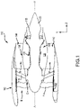
FIG. 1 illustrates a gas turbine engine, in accordance with various embodiments; -
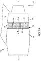
FIG. 2A illustrates a side view of a gas turbine engine with a thrust reverser in a deployed position, in accordance with various embodiments; -
FIG. 2B illustrates a cross-section view of gas turbine engine with a blocker door in a stowed position, in accordance with various embodiments; -
FIG. 2C illustrates a cross-section view of gas turbine engine with a blocker door in a deployed position, in accordance with various embodiments; -
FIG. 3 illustrates a perspective view of a thrust reverser blocker door, in accordance with various embodiments; -
FIG. 4 illustrates a perspective view of a thrust reverser blocker door, in accordance with various embodiments; -
FIG. 5 illustrates a flow chart of a method for manufacturing a thrust reverser blocker door, in accordance with various embodiments; -
FIG. 6A, FIG. 6B, FIG. 6C, FIG. 6D, FIG. 6E , andFIG. 6F illustrate various steps in manufacturing a thrust reverser blocker door in accordance with the method ofFIG. 5 , in accordance with various embodiments; -
FIG. 7 illustrates a flow chart of a method for manufacturing a thrust reverser blocker door, in accordance with various embodiments; -
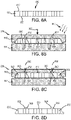
FIG. 8A, FIG. 8B, FIG. 8C, and FIG. 8D illustrate various steps in manufacturing a thrust reverser blocker door in accordance with the method ofFIG. 7 , in accordance with various embodiments; -
FIG. 9A, FIG. 9B, FIG. 9C, and FIG. 9D illustrate various steps in manufacturing a thrust reverser blocker door in accordance with the method ofFIG. 10 , in accordance with various embodiments; and -
FIG. 10 illustrates a flow chart of a method for manufacturing a thrust reverser blocker door, in accordance with various embodiments. - The detailed description of exemplary embodiments herein makes reference to the accompanying drawings, which show exemplary embodiments by way of illustration. While these exemplary embodiments are described in sufficient detail to enable those skilled in the art to practice the disclosure, it should be understood that other embodiments may be realized and that logical changes and adaptations in design and construction may be made in accordance with this disclosure and the teachings herein. Thus, the detailed description herein is presented for purposes of illustration only and not of limitation. The scope of the disclosure is defined by the appended claims. For example, the steps recited in any of the method or process descriptions may be executed in any order and are not necessarily limited to the order presented. Furthermore, any reference to singular includes plural embodiments, and any reference to more than one component or step may include a singular embodiment or step. Also, any reference to attached, fixed, connected or the like may include permanent, removable, temporary, partial, full and/or any other possible attachment option. Additionally, any reference to without contact (or similar phrases) may also include reduced contact or minimal contact. Surface shading lines may be used throughout the figures to denote different parts but not necessarily to denote the same or different materials. In some cases, reference coordinates may be specific to each figure.
- As used herein, "aft" refers to the direction associated with the tail (e.g., the back end) of an aircraft, or generally, to the direction of exhaust of the gas turbine. As used herein, "forward" refers to the direction associated with the nose (e.g., the front end) of an aircraft, or generally, to the direction of flight or motion.
- As used herein, "distal" refers to the direction radially outward, or generally, away from the axis of rotation of a turbine engine. As used herein, "proximal" refers to a direction radially inward, or generally, towards the axis of rotation of a turbine engine.
- Methods for manufacturing a blocker door are disclosed herein. In various embodiments, a method for manufacturing a blocker door includes thermoforming the blocker door from a sandwich panel comprising a facesheet, a backsheet, and a honeycomb core. The method may further include perforating the facesheet of the thermoformed sandwich panel. By thermoforming a sandwich panel having the honeycomb core already disposed between the facesheet and backsheet, the method provides design freedom and flexibility of shaping the blocker door while maximizing the acoustically treated area of the blocker door. Stated differently, the acoustically treated area of the blocker door may include substantially all areas of the blocker door where the facesheet and the backsheet are still spaced apart after being thermoformed.
- In various embodiments, a method for manufacturing a blocker door includes combining a thermoforming process with an injection molding process, also referred herein as an overmolding process. In this manner, overmolding combines the high specific strength and stiffness of the continuous fibers of a thermoformed blocker door with the design freedom and flexibility of (short fiber reinforced) injection molded mounting structures. Furthermore, the method includes manufacturing the blocker door from a single-piece sandwich panel, thereby simplifying the manufacturing process and reducing cycle time and cost.
-
FIG. 1 illustrates a schematic view of a gas turbine engine, in accordance with various embodiments. Xyz-axes are provided for ease of illustration.Gas turbine engine 110 may includecore engine 120. Core air flow C flows throughcore engine 120 and is expelled throughexhaust outlet 118 surroundingtail cone 122. -
Core engine 120 drives afan 114 arranged in a bypass flow path B. Air in bypass flow-path B flows in the aft direction (z-direction) along bypass flow-path B. At least a portion of bypass flow path B may be defined bynacelle 112 and inner fixed structure (IFS) 126.Fan case 132 may surroundfan 114.Fan case 132 may be housed withinfan nacelle 112.Fan 114 may rotate about an engine centerline axis A-A'. -
Nacelle 112 typically comprises two halves which are typically mounted to a pylon. According to various embodiments,multiple guide vanes 116 may extend radially betweencore engine 120 andfan case 132.Upper bifurcation 144 and lower bifurcation 142 may extend radially between thenacelle 112 andIFS 126 in locations opposite one another to accommodate engine components such as wires and fluids, for example. - Inner
fixed structure 126 surroundscore engine 120 and provides core compartments 128. Various components may be provided incore compartment 128 such as fluid conduits and/or compressed air ducts, for example. - With reference to
FIG. 2A , a side view ofgas turbine engine 110 is illustrated, in accordance with various embodiments.Gas turbine engine 110 may comprise a turbofan engine.Gas turbine engine 110 may be mounted onto an aircraft bypylon 212.Gas turbine engine 110 may includesegmented cowl 213 which includesnacelle body 214 and translatingcowl 216 and IFS 126 (with momentary reference toFIG. 1 ). Translatingcowl 216 is split fromnacelle body 214 and translates aft to produce reverse thrust. - A plurality of cascade vane sets 222 may be uncovered in response to translating
cowl 216 being translated aft as seen inFIG. 2A . Each of cascade vane sets 222 may include a plurality of conventional transverse, curved, turning vanes which turn airflow passing out from bypass flow path B (seeFIG. 1 ) through the cascade sets in an outwardly and forwardly direction relative togas turbine engine 110.Islands 224 are provided between cascade vane sets 222 to support the translation of translatingcowl 216 and support the sides of cascade vane sets 222. In the stowed position, translatingcowl 216 is translated forwardly to cover cascade vane sets 222 and provide a smooth, streamlined surface for air flow during normal flight operations. - With reference to
FIG. 2B , a cross-section view ofgas turbine engine 110 withblocker door 228 in a stowed position is illustrated, in accordance with various embodiments.Cascade 230 shown inFIG. 2B is one of many cascade vane sets 222 disposed circumferentially aroundgas turbine engine 110 as shown inFIG. 2A . Anactuator 268 may be disposed between these sets of cascades in order to drive translatingcowl 216 aftward. After a thrust reversing operation is completed,actuators 268 may returnblocker door 228 to the stowed position.Actuator 268 can be a ballscrew actuator, hydraulic actuator, or any other actuator known in the art. In various embodiments,multiple actuators 268 may be spaced aroundgas turbine engine 110 in between cascade vane sets 222. Although illustrated inFIG. 2B andFIG. 2C as being radially in-line withcascade 230,actuator 268 may be located radially inward, radially outward, or in any location relative to cascade 230. - Blocker door (also referred to herein as thrust reverser blocker door) 228 may be engaged with translating
cowl 216. In various embodiments,blocker door 228 may be engaged with translatingcowl 216 throughbracket 270. In various embodiments,bracket 270 and translatingcowl 216 may comprise a single, unitary member. Pivot 272 may be a hinge attachment betweenblocker door 228 andbracket 270. In various embodiments,blocker door 228 may be engaged directly to translatingcowl 216 through a hinge attachment. Pivot 272 may allowblocker door 228 to rotate as translatingcowl 216 moves from a stowed position to a deployed position. - With combined reference to
FIG. 2B andFIG. 2C , adrag link 256 may be coupled betweenblocker door 228 andIFS 126.Drag link 256 may be configured to pivot about afirst end 252. Stated another way,first end 252 ofdrag link 256 may be rotatably coupled toIFS 126.Second end 254 ofdrag link 256 may be rotatably coupled toblocker door 228. - With respect to
FIG. 2C , elements with like element numbering, as depicted inFIG. 2B , are intended to be the same and will not necessarily be repeated for the sake of clarity. - With reference to
FIG. 2C , a cross-section view ofgas turbine engine 110 withblocker door 228 in a deployed position is illustrated, in accordance with various embodiments. Thus,FIG. 2C showsgas turbine engine 110 in a reverse thrust mode.Blocker door 228 and its associated linkage system are responsive to translation of translatingcowl 216 during a thrust reversing sequence. As noted above and with momentary additional reference toFIG. 1 ,FIG. 2B shows a normal or cruise mode where fan air is directed through bypass flow path B. When in reverse thrust mode or deployed position, shown inFIG. 2C , bypass flow path B is blocked by one or more circumferentially disposedblocker doors 228, interposed within bypass flow path B and collectively having a complementary geometric configuration with respect thereto, for diversion of fan air intobypass duct 246. The reverse thrust mode is achieved by aftward movement of translatingcowl 216, thereby exposingoutlet port 274 for airflow to escape through after the air passes intobypass duct 246.Blocker door 228 may comprise a proximal surface, or anaerodynamic surface 229. - With reference to
FIG. 3 , a perspective view of anexemplary blocker door 300 is illustrated, in accordance with various embodiments.Blocker door 300 may comprise abody portion 305 comprising a first skin (also referred to herein as a backsheet) 310, a second skin (also referred to herein as a facesheet 320), and ahoneycomb core 330.Blocker door 300 may comprise a plurality of mountingstructures 340 coupled to thebacksheet 310 ofbody portion 305. In various embodiments,body portion 305 is manufactured as a single monolithic piece. In various embodiments,backsheet 310,facesheet 320, andhoneycomb core 330 are molded from a thermoplastic material such thatbacksheet 310,facesheet 320, andhoneycomb core 330 are monolithically formed. In various embodiments,facesheet 320 and plurality of mountingstructures 340 are molded from a thermoplastic material such thatfacesheet 320 and plurality of mountingstructures 340 are integrally formed, as will be described in further detail herein. In various embodiments, plurality of mountingstructures 340 are bonded to backsheet 310 via interdiffusion during an overmolding process, as described herein. Molding of the thermoplastic material may be done by either injection molding or compression molding. In various embodiments, any thermoplastic material molding process may be used to integrally formbacksheet 310,facesheet 320, andhoneycomb core 330. In various embodiments, the thermoplastic material includes at least one of polyetherether ketone, polyether sulfone, polyetherkeytone keytone, polyphenylsulfone, polyphenylene sulfide, polyetherimide, and polycarbonate. In various embodiments, the thermoplastic material includes any high temperature tolerant and chemically tolerant resin. - In various embodiments, the use of thermoplastic materials allows both the cell wall height and thickness of
honeycomb core 330 to be customized to meet desired specification. Furthermore, different portions of the honeycomb body portion may have different cell sizes to account for different loading or noise attenuation requirements. Such customization of the honeycomb cell size enables increased noise attenuation. - In various embodiments, plurality of mounting
structures 340 are bonded to backsheet 310 via a thermoplastic ultrasonic welding process. In various embodiments, thermoplastic ultrasonic welding may be a method of joining thermoplastic components by heating and subsequent melting of surfaces which are in contact with each other. Mechanical vibration with frequency between 10 and 70 kilohertz (kHz) and amplitude of 10 to 250 micrometers (µm) may be applied to joining parts. After ultrasonic energy is turned off, the parts remain in contact under pressure for a period of time while the melt layer cools down creating a weld. - In various embodiments, mounting
structures 340 may comprise an attachment feature wherebyblocker door 300 is mounted to a nacelle structure such as a translating cowl or an inner fixed structure for example. In various embodiments, mountingstructures 340 may include an attachment feature, such as a lug or a pin for example, wherebyblocker door 300 is coupled to drag link 256 (seeFIG. 2A andFIG. 2B ). In various embodiments, mountingstructures 340 may include an attachment feature, such as a lug or a pin for example, wherebyblocker door 300 is coupled to bracket 270 (seeFIG. 2A andFIG. 2B ). In various embodiments, mountingstructures 340 may be similar to pivot 272 (seeFIG. 2A andFIG. 2B ). - In various embodiments,
honeycomb core 330 includes a plurality ofcells 332 that include a plurality ofwalls 334 to form eachcell 332. As described above,honeycomb core 330 is customizable such that the thickness and height ofwalls 334 changes based on their location onbody 130. - With reference to
FIG. 4 , a perspective view of anexemplary blocker door 400 is illustrated, in accordance with various embodiments.Blocker door 400 may comprise abody portion 405 comprising abacksheet 410, afacesheet 420, and ahoneycomb core 430.Blocker door 400 may comprise a plurality of mountingstructures 440 coupled to thebacksheet 410 ofbody portion 405.Blocker door 400 may be similar toblocker door 300 except that the mountingstructures 440 ofblocker door 400 are coupled to backsheet 410 via a plurality offasteners 442, such as bolts, rivets, screws, or the like. Thus, mountingstructures 440 may be coupled tobacksheet 410 via interfusion during an overmolding process or may be coupled tobacksheet 410 afterblocker door 400 is thermoformed, as described herein with further detail. - With reference to
FIG. 5 , amethod 500 for manufacturing a blocker door, in accordance with various embodiments.Method 500 includes thermoforming a thermoplastic composite sandwich panel into a blocker door and subsequently, or simultaneously, overmolding the thermoformed blocker door with a thermoplastic composite material to form mounting structures thereon.Method 500 includes placing a sandwich panel into a first mold (step 520).Method 500 includes thermoforming the sandwich panel in the first mold (step 530).Method 500 includes removing the sandwich panel from the first mold (step 540).Method 500 includes placing the sandwich panel into a second mold (step 550).Method 500 includes injecting a cavity with a flow of thermoplastic material (step 560).Method 500 includes perforating a facesheet of the sandwich panel (step 570). - With reference to
FIG. 6A , asandwich panel 600 is illustrated, in accordance with various embodiments.Sandwich panel 600 may comprise abacksheet 610, afacesheet 620, ahoneycomb core 630.Sandwich panel 600 may be made from a thermoplastic.Backsheet 610,facesheet 620, and/orhoneycomb core 630 may be made from a continuous fiber reinforced thermoplastic composite material (also referred to herein as a first thermoplastic material). The term "continuous fiber reinforced thermoplastic composite material" as used herein may refer to a composite material that contains continuous fibers, such as carbon fiber, glass fiber, or aramid fiber that is impregnated in a matrix of thermoplastics, such as a polycarbonate, among others.Sandwich panel 600 may be formed as a single piece.Sandwich panel 600 may be formed using injection molding, compression molding, or any other suitable manufacturing method. It is appreciated that the method of formingsandwich panel 600 is not particularly limited. - In various embodiments,
sandwich panel 600 is a single degree of freedom (SDOF) acoustic panel. In various embodiments,sandwich panel 600 is a double degree of freedom (DDOF) acoustic panel. In this regard, a septum, or additional sheet, may appear in between layers ofhoneycomb core 630 as well as in a stack up comprising, for example, a facesheet, honeycomb core, septum, honeycomb core, and backsheet, thereby dividing one or more cells ofhoneycomb core 630 into two chambers, in accordance with various embodiments. - With reference to
FIG. 6B ,sandwich panel 600 is illustrated in afirst mold 681. With combined reference toFIG. 5 andFIG. 6B ,step 520 may include placingsandwich panel 600 intofirst mold 681. In various embodiments,first mold 681 comprises afirst plate 642 and asecond plate 644. Step 520 may include placingsandwich panel 600 betweenfirst plate 642 andsecond plate 644. - With combined reference to
FIG. 5 andFIG. 6B ,step 530 may includethermoforming sandwich panel 600 infirst mold 681. Step 530 may include compressingsandwich panel 600 betweenfirst plate 642 andsecond plate 644. In this regard, aforce 652 may be applied tofirst plate 642 thereby movingfirst plate 642 towardsecond plate 644.First plate 642 may comprise acontoured surface 643.Second plate 644 may comprise acontoured surface 645. Asfirst plate 642 moves towardsecond plate 644, thesandwich panel 600 is compressed betweenfirst plate 642 andsecond plate 644, thereby forcingsandwich panel 600 against contouredsurface 643 and contouredsurface 645.Sandwich panel 600 is thereby deformed (i.e., thermoformed) in response to being compressed betweenfirst plate 642 andsecond plate 644 in accordance with the shape offirst plate 642 andsecond plate 644. In this manner,backsheet 610,facesheet 620, and honeycomb core 630 (seeFIG. 6A ) may be simultaneously deformed during the thermoforming process. In various embodiments,backsheet 610 andfacesheet 620 may be compressed together around theperimeter 604 ofsandwich panel 600 to completely enclosehoneycomb core 630 during the thermoforming process. - In various embodiments,
step 530 may include applying heat (illustrated by arrows 650) tosandwich panel 600 such thatsandwich panel 600 reaches a pliable forming temperature. In various embodiments, the heat is applied tosandwich panel 600 before it is placed betweenfirst plate 642 andsecond plate 644. In various embodiments, the heat is applied tosandwich panel 600 after it is placed betweenfirst plate 642 andsecond plate 644. In various embodiments, the heat is applied by placingsandwich panel 600 into a furnace. However, any suitable method of applying heat tosandwich panel 600 may be used.Sandwich panel 600 may be placed intofirst mold 681 before or after the heat is applied thereto. Once cooled, thesandwich panel 600 may retain the shape of the contouredsurfaces first plate 642 andsecond plate 644, respectively. - In various embodiments, it is contemplated that
step 530 may further include applying vacuum to remove trapped air between the molds and the sandwich panel and to pull the sandwich panel into or onto the mold to form the thermoplastic to the detailed shape of the mold. In various embodiments, it is contemplated thatstep 530 may further include applying pressurized air to the sandwich panel to form the plastic to the detailed shape of the mold. - With reference to
FIG. 6C ,sandwich panel 600 is illustrated after being cooled and removed from the molds, now in the form of athermoformed blocker door 602. With combined reference toFIG. 5 andFIG. 6C ,step 540 may include removing thesandwich panel 600 fromfirst mold 681. - With reference to
FIG. 6D ,thermoformed blocker door 602 is illustrated insecond mold 682. With combined reference toFIG. 5 andFIG. 6D ,step 550 may include placingsandwich panel 600 intosecond mold 682. Step 550 may include placingsandwich panel 600 betweenthird plate 672 andfourth plate 674. Although described as afourth plate 674, it is contemplated herein thatsecond plate 644 may be used instep 550, wherein thefirst plate 642 is replaced with thethird plate 672, with momentary reference toFIG. 6B .Cavities 666 may be formed betweencontoured surfaces 664 ofsandwich panel 600 andthird plate 672 ofsecond mold 682.Contoured surfaces 664 may be shaped in the form of a mounting structure, such as, for example, the mountingstructures 340 ofFIG. 3 . - In various embodiments,
step 560 may include injecting (overmolding)cavities 666 with a flow of thermoplastic material (also referred to herein as a second thermoplastic material) 660. In various embodiments,thermoplastic material 660 is a discontinuous fiber (also referred to as a short fiber) reinforced thermoplastic composite material. The term "discontinuous fiber reinforced thermoplastic material" as used herein may refer to a composite material that contains a plurality of discontinuous fibers, such as carbon fiber, glass fiber, or aramid fiber that is impregnated in a matrix of thermoplastics, such as polycarbonate, among others.Thermoplastic material 660 may comprise between 10% and 50% fiber by weight. Thethermoplastic material 660 may be heated to a temperature such the thatthermoplastic material 660 is melted and flows throughapertures 662 disposed inthird plate 672 and fillscavities 666. As the flow ofthermoplastic material 660 fillscavities 666, thethermoplastic material 660contacts sandwich panel 600 causing localized heating ofsandwich panel 600 such thatthermoplastic material 660 bonds with thebacksheet 610 ofsandwich panel 600 through adhesion and interdiffusion. It is appreciated that the type of thermoplastic material used forthermoplastic material 660 andbacksheet 610 may affect the bond strength betweenthermoplastic material 660 andbacksheet 610 during the overmolding process. In various embodiments,cavities 666 may be shaped as mounting structures, such as mountingstructures 340 ofFIG. 3 for example. In this regard, and with additional reference toFIG. 6E ,thermoplastic material 660 that fillscavities 666 may be cooled and retain the shape ofcavities 666 thereby forming mountingstructures 668 on thebacksheet 610 ofthermoformed blocker door 602. In various embodiments, mountingstructures 668 are similar to mountingstructures 340 ofFIG. 3 . - In various embodiments, with combined reference to
FIG. 5 andFIG. 6F , step 570 may include perforatingfacesheet 620 of thesandwich panel 600. In this manner, a plurality ofopenings 622 may be formed intofacesheet 620. The plurality ofopenings 622 may be in fluid communication withhoneycomb core 630, with momentary reference toFIG 6E . In this manner,blocker door 602 may be acoustically treated for attenuating noise generated during engine operation. In various embodiments,step 570 is performed using a perforation process. - Having described a method 500 (see
FIG. 5 ) for manufacturing a blocker door where the blocker door is moved between separate molds for thermoforming and overmolding, respectively, and with reference now toFIG. 7 , amethod 700 for manufacturing a blocker door is disclosed using common molds for thermoforming and overmolding, respectively, in accordance with various embodiments.Method 700 includes thermoforming a thermoplastic composite sandwich panel into a blocker door and subsequently, or simultaneously, overmolding the thermoformed blocker door with a thermoplastic composite material to form mounting structures thereon.Method 700 includes placing the sandwich panel into a first mold (step 720).Method 700 includes thermoforming the sandwich panel in the first mold (step 730).Method 700 includes injecting a cavity with a flow of thermoplastic material (step 740).Method 700 includes perforating a facesheet of the sandwich panel (step 750). - With reference to
FIG. 8A , asandwich panel 800 is illustrated, in accordance with various embodiments.Sandwich panel 800 may comprise abacksheet 810, afacesheet 820, ahoneycomb core 830.Sandwich panel 800 may be similar tosandwich panel 600 ofFIG. 6A . - With reference to
FIG. 8B ,sandwich panel 800 is illustrated in afirst mold 880. With combined reference toFIG. 7 andFIG. 8B ,step 720 may include placingsandwich panel 800 intofirst mold 880.First mold 880 may include afirst plate 842 and asecond plate 844. Step 720 may include placingsandwich panel 800 betweenfirst plate 842 andsecond plate 844. - With combined reference to
FIG. 7 andFIG. 8B ,step 730 may includethermoforming sandwich panel 800 infirst mold 880. Step 730 may include compressingsandwich panel 800 betweenfirst plate 842 andsecond plate 844. In this regard, aforce 852 may be applied tofirst plate 842 thereby movingfirst plate 842 towardsecond plate 844.First plate 842 may comprise acontoured surface 843.Second plate 844 may comprise acontoured surface 845. Asfirst plate 842 moves towardsecond plate 844, thesandwich panel 800 is compressed betweenfirst plate 842 andsecond plate 844, thereby forcingsandwich panel 800 against contouredsurface 843 and contouredsurface 845.Sandwich panel 800 is thereby deformed (i.e., thermoformed) in response to being compressed betweenfirst plate 842 andsecond plate 844 in accordance with the shape offirst plate 842 andsecond plate 844. In this manner,backsheet 810,facesheet 820, and honeycomb core 830 (seeFIG. 8A ) may be simultaneously deformed during the thermoforming process. - With combined reference to
FIG. 7 andFIG. 8B ,step 730 may include applying heat (illustrated by arrows 850) tosandwich panel 800 such thatsandwich panel 800 reaches a pliable forming temperature. In various embodiments, the heat is applied tosandwich panel 800 before it is placed betweenfirst plate 842 andsecond plate 844. In various embodiments, the heat is applied tosandwich panel 800 after it is placed betweenfirst plate 842 andsecond plate 844. In various embodiments, the heat is applied by placingsandwich panel 800 into a furnace. However, any suitable method of applying heat tosandwich panel 800 may be used.Sandwich panel 800 may be placed betweenfirst plate 842 andsecond plate 844 before or after the heat is applied thereto. Once cooled, thesandwich panel 800 may retain the shape of the contouredsurfaces first plate 842 andsecond plate 844, respectively. - In various embodiments,
cavities 866 may be formed betweencontoured surfaces 864 ofsandwich panel 800 andfirst plate 842.Contoured surfaces 864 may be shaped in the form of a mounting structure, such as, for example, the mounting structures 840 ofFIG. 3 . - In various embodiments, with combined reference to
FIG. 7 andFIG. 8C ,step 740 may include injecting (overmolding)cavities 866 with a flow ofthermoplastic material 860. In various embodiments,thermoplastic material 860 is similar to thermoplastic material 660 (seeFIG. 6D ). Thethermoplastic material 860 may be heated to a temperature such the thatthermoplastic material 860 is melted and flows throughapertures 862 disposed infirst plate 842 and fillscavities 666. As the flow ofthermoplastic material 860 fillscavities 866, thethermoplastic material 860contacts sandwich panel 800 causing localized heating ofsandwich panel 800 such thatthermoplastic material 860 bonds with thebacksheet 810 ofsandwich panel 800 through adhesion and interdiffusion. It is appreciated that the type of thermoplastic material used forthermoplastic material 860 andbacksheet 810 may affect the bond strength betweenthermoplastic material 860 andbacksheet 810 during the overmolding process. In various embodiments,cavities 866 may be shaped as mounting structures, such as mountingstructures 340 ofFIG. 3 for example. In this regard, and with additional reference toFIG. 8D ,thermoplastic material 860 that fillscavities 866 may be cooled and retain the shape ofcavities 866 thereby forming mountingstructures 868 on thebacksheet 810 ofthermoformed blocker door 802. In various embodiments, mountingstructures 868 are similar to mountingstructures 340 ofFIG. 3 . - With combined reference to
FIG. 7 andFIG. 8D ,step 750 may be performed afterstep 740 is complete. Step 750 may include perforatingfacesheet 820 ofthermoformed blocker door 802. Step 750 may be similar to step 570 of method 500 (seeFIG. 5 andFIG. 6E ). - With reference to
FIG. 9A , asandwich panel 900 is illustrated, in accordance with various embodiments.Sandwich panel 900 may be similar to sandwich panel 600 (seeFIG. 6A ).Sandwich panel 900 may comprise abacksheet 910, afacesheet 920, ahoneycomb core 930.Sandwich panel 900 may be made from a thermoplastic. - With reference to
FIG. 9B ,sandwich panel 900 is illustrated in afirst mold 980.First mold 980 may comprise afirst plate 942 and asecond plate 944. With momentary reference toFIG. 10 , a flow chart for amethod 990 for manufacturing a blocker door is illustrated in accordance with various embodiments. With combined reference toFIG. 10 andFIG. 9B ,step 992 may include placingsandwich panel 900 intofirst mold 980. Step 992 may include placingsandwich panel 900 betweenfirst plate 942 andsecond plate 944. - With combined reference to
FIG. 10 andFIG. 9B ,step 993 may includethermoforming sandwich panel 900 infirst mold 980. Step 993 may include compressingsandwich panel 900 betweenfirst plate 942 andsecond plate 944. In this regard, aforce 952 may be applied tofirst plate 942 thereby movingfirst plate 942 towardsecond plate 944.First plate 942 may comprise acontoured surface 943.Second plate 944 may comprise acontoured surface 945. Asfirst plate 942 moves towardsecond plate 944, thesandwich panel 900 is compressed betweenfirst plate 942 andsecond plate 944, thereby forcingsandwich panel 900 against contouredsurface 943 and contouredsurface 945.Sandwich panel 900 is thereby deformed (i.e., thermoformed) in response to being compressed betweenfirst plate 942 andsecond plate 944 in accordance with the shape offirst plate 942 andsecond plate 944. In this manner,backsheet 910,facesheet 920, andhoneycomb core 930 may be simultaneously deformed during the thermoforming process. In various embodiments,backsheet 910 andfacesheet 920 may remain spaced apart from each other during the thermoforming process. In this regard, a gap betweenbacksheet 910 andfacesheet 920 around theperimeter 904 ofsandwich panel 900 may exposehoneycomb core 930. - With combined reference to
FIG. 10 andFIG. 9B ,step 993 may include applying heat (illustrated by arrows 950) tosandwich panel 900 such thatsandwich panel 900 reaches a pliable forming temperature. In various embodiments, the heat is applied tosandwich panel 900 before it is placed betweenfirst plate 942 andsecond plate 944. In various embodiments, the heat is applied tosandwich panel 900 after it is placed betweenfirst plate 942 andsecond plate 944. In various embodiments, the heat is applied by placingsandwich panel 900 into a furnace. However, any suitable method of applying heat tosandwich panel 900 may be used.Sandwich panel 900 may be placed betweenfirst plate 942 andsecond plate 944 before or after the heat is applied thereto. Once cooled, thesandwich panel 900 may retain the shape of the contouredsurfaces first plate 942 andsecond plate 944, respectively. - With reference to
FIG. 9C ,sandwich panel 900 is illustrated after being cooled and removed from the mold, now in the form of athermoformed blocker door 902. With combined reference toFIG. 10 andFIG. 9C ,step 994 may include removing thesandwich panel 900 fromfirst mold 980. - In various embodiments, one or more close-
outs 906 may be welded around theperimeter 904 ofthermoformed blocker door 902 to enclosehoneycomb core 930. In this regard,step 995 may include welding close-out 906 along theperimeter 904 ofsandwich panel 900. Close-outs 906 may be made from a thermoplastic material. Close-outs 906 may comprise a "U" shaped channel or ribbon structure extending betweenbacksheet 910 andfacesheet 920. Close-outs 906 may extend overbacksheet 910 andfacesheet 920. Close-outs 906 may be coupled tobacksheet 910 andfacesheet 920 via a thermoplastic ultrasonic welding process. - In various embodiments, mounting structures may be coupled to
thermoformed blocker door 902 via an overmolding process or via fasteners, as described herein. Furthermore,facesheet 920 may be perforated. - Benefits, other advantages, and solutions to problems have been described herein with regard to specific embodiments. Furthermore, the connecting lines shown in the various figures contained herein are intended to represent exemplary functional relationships and/or physical couplings between the various elements. It should be noted that many alternative or additional functional relationships or physical connections may be present in a practical system. However, the benefits, advantages, solutions to problems, and any elements that may cause any benefit, advantage, or solution to occur or become more pronounced are not to be construed as critical, required, or essential features or elements of the disclosure. The scope of the disclosure is accordingly to be limited by nothing other than the appended claims, in which reference to an element in the singular is not intended to mean "one and only one" unless explicitly so stated, but rather "one or more." Moreover, where a phrase similar to "at least one of A, B, or C" is used in the claims, it is intended that the phrase be interpreted to mean that A alone may be present in an embodiment, B alone may be present in an embodiment, C alone may be present in an embodiment, or that any combination of the elements A, B and C may be present in a single embodiment; for example, A and B, A and C, B and C, or A and B and C. Systems, methods and apparatus are provided herein. In the detailed description herein, references to "one embodiment", "an embodiment", "various embodiments", etc., indicate that the embodiment described may include a particular feature, structure, or characteristic, but every embodiment may not necessarily include the particular feature, structure, or characteristic. Moreover, such phrases are not necessarily referring to the same embodiment. Further, when a particular feature, structure, or characteristic is described in connection with an embodiment, it is submitted that it is within the knowledge of one skilled in the art to affect such feature, structure, or characteristic in connection with other embodiments whether or not explicitly described. After reading the description, it will be apparent to one skilled in the relevant art(s) how to implement the disclosure in alternative embodiments.
- Furthermore, no element, component, or method step in the present disclosure is intended to be dedicated to the public regardless of whether the element, component, or method step is explicitly recited in the claims. As used herein, the terms "comprises", "comprising", or any other variation thereof, are intended to cover a non-exclusive inclusion, such that a process, method, article, or apparatus that comprises a list of elements does not include only those elements but may include other elements not expressly listed or inherent to such process, method, article, or apparatus.
- Embodiments of the invention which are described but not claimed:
- Embodiment 1: A thrust reverser blocker door, comprising: a body portion (305) comprising a facesheet (320), a backsheet (310), and a honeycomb core (330); and a mounting structure (340) coupled to the backsheet (310); wherein at least one of the facesheet (320) and the backsheet (310) comprises a first thermoplastic material and the mounting structure (340) comprises a second thermoplastic material.
- Embodiment 2. The thrust reverser blocker door of embodiment 1, wherein the first thermoplastic material comprises a continuous fiber reinforced thermoplastic composite material.
- Embodiment 3. The thrust reverser blocker door of embodiment 1 or 2, wherein the second thermoplastic material comprises a discontinuous fiber reinforced thermoplastic composite material.
- Embodiment 4. The thrust reverser blocker door of embodiment 1, 2 or 3, wherein the mounting structure (340) is interdiffused with the backsheet (310) via an overmolding process; optionally further comprising a plurality of openings (622) disposed in the facesheet (620), wherein, preferably, the plurality of openings (622) are in fluid communication with the honeycomb core (630).
- Embodiment 5. The thrust reverser blocker door of any preceding embodiment, further comprising a close-out (906) coupled around a perimeter (904) of the thrust reverser blocker door.
- Embodiment 6. A method for manufacturing a thrust reverser blocker door, comprising: thermoforming a sandwich panel (600), the sandwich panel (600) comprising a facesheet (620), a backsheet (610), and a honeycomb core (630) disposed between the facesheet (620) and the backsheet (610); and overmolding a mounting structure (340) onto the backsheet (610).
-
Embodiment 7. The method of embodiment 6, wherein at least one of the facesheet (620) and the backsheet (610) comprises a first thermoplastic material and the mounting structure (340) comprises a second thermoplastic material. - Embodiment 8. The method of
embodiment 7, wherein the thermoforming comprises: applying heat to the sandwich panel (600); placing the sandwich panel (600) into a first mold (681); and compressing the sandwich panel (600) to shape in the first mold (681). - Embodiment 9. The method of
embodiment 7 or 8, wherein the overmolding comprises injecting a flow of the second thermoplastic material into a cavity disposed between at least one of the facesheet and the backsheet and a or the first mold. - Embodiment 10. The method of embodiment 9, wherein the second thermoplastic material is interdiffused with at least one of the facesheet and the backsheet in response to the flow of the second thermoplastic material being injected into the cavity.
- Embodiment 11. The method of embodiment 8, wherein the overmolding comprises: removing the sandwich panel from the first mold; placing the sandwich panel into a second mold; and injecting a flow of the second thermoplastic material into a cavity disposed between the backsheet and the second mold.
- Embodiment 12. A method for manufacturing a thrust reverser blocker door, comprising: thermoforming a sandwich panel, the sandwich panel comprising a facesheet, a backsheet, and a honeycomb core, wherein the thermoforming includes: applying heat to the sandwich panel; placing the sandwich panel into a first mold; and compressing the sandwich panel in the first mold.
- Embodiment 13. The method of embodiment 12, wherein the facesheet, the backsheet, and the honeycomb core are simultaneously deformed in response to the sandwich panel being compressed in the first mold.
- Embodiment 14. The method of any of embodiments 6-13, further comprising perforating the facesheet e.g. the facesheet of the sandwich panel.
- Embodiment 15. The method of any of embodiments 6-14, further comprising coupling a close-out along or around a perimeter of the sandwich panel.
Claims (4)
- A method for manufacturing a thrust reverser blocker door, comprising:thermoforming a sandwich panel (600), the sandwich panel (600) comprising a facesheet (620), a backsheet (610), and a honeycomb core (630),wherein the thermoforming includes:applying heat to the sandwich panel (600);placing the sandwich panel into a first mold (681); andcompressing the sandwich panel (600) in the first mold (681).
- The method of claim 1, wherein the facesheet (620), the backsheet (610), and the honeycomb core (630) are simultaneously deformed in response to the sandwich panel (600) being compressed in the first mold (681).
- The method of any of claims 1-2, further comprising perforating the facesheet (620) of the sandwich panel (600).
- The method of any of claims 1-3, further comprising coupling a close-out (906) along or around a perimeter (904) of the sandwich panel (900).
Applications Claiming Priority (2)
| Application Number | Priority Date | Filing Date | Title |
|---|---|---|---|
| US16/140,318 US11261825B2 (en) | 2018-09-24 | 2018-09-24 | Thermoplastic acoustic blocker door |
| EP19191136.1A EP3626958B1 (en) | 2018-09-24 | 2019-08-09 | Thermoplastic acoustic blocker door |
Related Parent Applications (2)
| Application Number | Title | Priority Date | Filing Date |
|---|---|---|---|
| EP19191136.1A Division-Into EP3626958B1 (en) | 2018-09-24 | 2019-08-09 | Thermoplastic acoustic blocker door |
| EP19191136.1A Division EP3626958B1 (en) | 2018-09-24 | 2019-08-09 | Thermoplastic acoustic blocker door |
Publications (2)
| Publication Number | Publication Date |
|---|---|
| EP3995686A1 true EP3995686A1 (en) | 2022-05-11 |
| EP3995686B1 EP3995686B1 (en) | 2024-07-31 |
Family
ID=67587693
Family Applications (2)
| Application Number | Title | Priority Date | Filing Date |
|---|---|---|---|
| EP19191136.1A Active EP3626958B1 (en) | 2018-09-24 | 2019-08-09 | Thermoplastic acoustic blocker door |
| EP21212294.9A Active EP3995686B1 (en) | 2018-09-24 | 2019-08-09 | Thermoplastic acoustic blocker door |
Family Applications Before (1)
| Application Number | Title | Priority Date | Filing Date |
|---|---|---|---|
| EP19191136.1A Active EP3626958B1 (en) | 2018-09-24 | 2019-08-09 | Thermoplastic acoustic blocker door |
Country Status (2)
| Country | Link |
|---|---|
| US (2) | US11261825B2 (en) |
| EP (2) | EP3626958B1 (en) |
Families Citing this family (11)
| Publication number | Priority date | Publication date | Assignee | Title |
|---|---|---|---|---|
| US10876480B2 (en) * | 2019-02-01 | 2020-12-29 | Pratt & Whitney Canada Corp. | Acoustic structure for gas turbine engine |
| FR3095677B1 (en) * | 2019-05-03 | 2021-04-09 | Safran Aircraft Engines | Thrust reverser grille including acoustic treatment |
| US12136407B2 (en) * | 2020-11-02 | 2024-11-05 | Pratt & Whitney Canada Corp. | Sandwich-structured panels and method of manufacture |
| FR3123689A1 (en) * | 2021-06-04 | 2022-12-09 | Airbus Operations (S.A.S.) | BLADE FOR THRUST REVERSER AND A METHOD OF MANUFACTURING SUCH BLADE |
| US12014712B2 (en) | 2021-09-02 | 2024-06-18 | Rohr, Inc. | Corrugated acoustic stiffening devices and methods |
| US11993388B2 (en) | 2021-09-02 | 2024-05-28 | Rohr, Inc. | Corrugated stiffening devices utilizing peaks and valleys and methods of manufacture |
| US11780179B2 (en) | 2021-09-02 | 2023-10-10 | Rohr, Inc. | Thermoplastic composite panel with corrugated peaks and troughs stiffening systems and methods |
| FR3127433A1 (en) * | 2021-09-29 | 2023-03-31 | Airbus Operations (S.A.S.) | Method of manufacturing a door of a thrust reverser system, thrust reverser system door thus obtained and aircraft propulsion assembly comprising several of said doors |
| DE102022129653A1 (en) | 2022-11-09 | 2024-05-16 | Rolls-Royce Deutschland Ltd & Co Kg | Method for producing an acoustically damping cellular structure, acoustically damping cellular structure and flow-guiding component with several acoustically damping cellular structures |
| US20240217150A1 (en) * | 2023-01-03 | 2024-07-04 | Rohr, Inc. | Manufacturing thrust reverser blocker door using overmolding |
| US12529348B1 (en) * | 2024-07-16 | 2026-01-20 | Rohr, Inc. | Linkage damper for aircraft component |
Citations (4)
| Publication number | Priority date | Publication date | Assignee | Title |
|---|---|---|---|---|
| WO2005016643A1 (en) * | 2002-04-30 | 2005-02-24 | Aerospace Composite Structures, Llc | Method of thermoforming frtp sandwich panels, thermoformed articles, modular container |
| US20150090524A1 (en) * | 2012-06-12 | 2015-04-02 | Aircelle | Method for producing foam panels, especially for the field of aeronautics |
| US9662854B2 (en) * | 2012-03-30 | 2017-05-30 | Daimler Ag | Sandwich composite component and production process therefor |
| EP3290195A1 (en) * | 2016-08-29 | 2018-03-07 | The Boeing Company | Compression molding assembly and methods for molding a thermoplastic blocker door |
Family Cites Families (13)
| Publication number | Priority date | Publication date | Assignee | Title |
|---|---|---|---|---|
| US5575147A (en) | 1994-12-22 | 1996-11-19 | United Technologies Corporation | Compact thrust reverser |
| US6428738B1 (en) * | 1995-11-01 | 2002-08-06 | Patent Holding Company | Method of manufacturing an in-mold laminate component |
| FR2841031B1 (en) * | 2002-06-17 | 2005-02-11 | Hurel Hispano Le Havre | PROCESS FOR PRODUCING A DOUBLE RESONATOR ACOUSTIC PANEL |
| KR20060036449A (en) * | 2003-07-14 | 2006-04-28 | 히타치 긴조쿠 가부시키가이샤 | Ceramic honeycomb filter and its manufacturing method |
| US7861708B1 (en) * | 2006-02-03 | 2011-01-04 | Fasco Industries, Inc. | Draft inducer blower mounting feature which reduces overall system vibration |
| WO2010122026A1 (en) * | 2009-04-22 | 2010-10-28 | Dsm Ip Assets B.V. | Plastic housing of a radial flow compressor |
| WO2012133848A1 (en) * | 2011-03-31 | 2012-10-04 | 日本碍子株式会社 | Sealed honeycomb structure |
| EP2761728A1 (en) * | 2011-09-30 | 2014-08-06 | Moog Inc. | Motorized blower assemblies, and methods of making same |
| US20140186166A1 (en) * | 2012-12-27 | 2014-07-03 | General Electric Company | Hybrid Continuous Fiber Chopped Fiber Polymer Composite Structure |
| WO2015090574A1 (en) * | 2013-12-17 | 2015-06-25 | Daimler Ag | Method for producing a sandwich component, and sandwich component |
| US9623977B2 (en) * | 2014-03-20 | 2017-04-18 | The Boeing Company | Hybrid structure including built-up sandwich structure and monolithic SPF/DB structure |
| US9845769B2 (en) | 2015-05-05 | 2017-12-19 | Rohr, Inc. | Plastic core blocker door |
| US10794326B2 (en) | 2016-08-29 | 2020-10-06 | The Boeing Company | Blocker door assembly having a thermoplastic blocker door for use in a turbine engine |
-
2018
- 2018-09-24 US US16/140,318 patent/US11261825B2/en active Active
-
2019
- 2019-08-09 EP EP19191136.1A patent/EP3626958B1/en active Active
- 2019-08-09 EP EP21212294.9A patent/EP3995686B1/en active Active
-
2022
- 2022-01-24 US US17/648,764 patent/US20220145828A1/en not_active Abandoned
Patent Citations (4)
| Publication number | Priority date | Publication date | Assignee | Title |
|---|---|---|---|---|
| WO2005016643A1 (en) * | 2002-04-30 | 2005-02-24 | Aerospace Composite Structures, Llc | Method of thermoforming frtp sandwich panels, thermoformed articles, modular container |
| US9662854B2 (en) * | 2012-03-30 | 2017-05-30 | Daimler Ag | Sandwich composite component and production process therefor |
| US20150090524A1 (en) * | 2012-06-12 | 2015-04-02 | Aircelle | Method for producing foam panels, especially for the field of aeronautics |
| EP3290195A1 (en) * | 2016-08-29 | 2018-03-07 | The Boeing Company | Compression molding assembly and methods for molding a thermoplastic blocker door |
Also Published As
| Publication number | Publication date |
|---|---|
| EP3626958B1 (en) | 2022-01-12 |
| EP3626958A1 (en) | 2020-03-25 |
| EP3995686B1 (en) | 2024-07-31 |
| US20200095955A1 (en) | 2020-03-26 |
| US20220145828A1 (en) | 2022-05-12 |
| US11261825B2 (en) | 2022-03-01 |
Similar Documents
| Publication | Publication Date | Title |
|---|---|---|
| US20220145828A1 (en) | Thermoplastic acoustic blocker door | |
| US4826106A (en) | Advanced composite aircraft cowl | |
| US6129311A (en) | Engine nacelle outer cowl panel with integral track fairings | |
| US9845769B2 (en) | Plastic core blocker door | |
| EP3141375B1 (en) | Additive manufacturing a fiber-reinforced thrust reverser cascade assembly | |
| EP3044415B1 (en) | Airfoil with an integrally stiffened composite cover | |
| EP3594127B1 (en) | Active laminar flow control system with composite panel | |
| EP3584434B1 (en) | Thrust reverser cascade and method of manufacture | |
| EP3105446A1 (en) | Thrust reverser cascade | |
| CN110654527B (en) | Acoustic panel for thrust reverser | |
| US10507931B2 (en) | Panel and insert for corner radii | |
| US20220176614A1 (en) | Forming a thrust reverser cascade using corrugated bodies | |
| AU2003263241A1 (en) | Method for making a soundproofing panel with at least one double resonator | |
| US20240110535A1 (en) | Thrust reverser cascade and method of manufacture | |
| EP4306420B1 (en) | Nacelle inlet assembly with acoustic panel | |
| US20240018881A1 (en) | Nacelle inlet assembly that promotes laminar flow | |
| US20200392923A1 (en) | Thrust reverser cascade and method of manufacture | |
| EP4397850A1 (en) | Manufacturing thrust reverser blocker door using overmolding | |
| EP4108443A1 (en) | Acoustic panel and method of forming same | |
| EP4306418B1 (en) | Nacelle inlet assembly with composite lipskin | |
| CN117401151A (en) | Nacelle inlet assembly with composite lip skin |
Legal Events
| Date | Code | Title | Description |
|---|---|---|---|
| PUAI | Public reference made under article 153(3) epc to a published international application that has entered the european phase |
Free format text: ORIGINAL CODE: 0009012 |
|
| STAA | Information on the status of an ep patent application or granted ep patent |
Free format text: STATUS: THE APPLICATION HAS BEEN PUBLISHED |
|
| AC | Divisional application: reference to earlier application |
Ref document number: 3626958 Country of ref document: EP Kind code of ref document: P |
|
| AK | Designated contracting states |
Kind code of ref document: A1 Designated state(s): AL AT BE BG CH CY CZ DE DK EE ES FI FR GB GR HR HU IE IS IT LI LT LU LV MC MK MT NL NO PL PT RO RS SE SI SK SM TR |
|
| STAA | Information on the status of an ep patent application or granted ep patent |
Free format text: STATUS: REQUEST FOR EXAMINATION WAS MADE |
|
| 17P | Request for examination filed |
Effective date: 20221111 |
|
| RBV | Designated contracting states (corrected) |
Designated state(s): AL AT BE BG CH CY CZ DE DK EE ES FI FR GB GR HR HU IE IS IT LI LT LU LV MC MK MT NL NO PL PT RO RS SE SI SK SM TR |
|
| GRAP | Despatch of communication of intention to grant a patent |
Free format text: ORIGINAL CODE: EPIDOSNIGR1 |
|
| STAA | Information on the status of an ep patent application or granted ep patent |
Free format text: STATUS: GRANT OF PATENT IS INTENDED |
|
| RIC1 | Information provided on ipc code assigned before grant |
Ipc: B29C 70/74 20060101ALI20240206BHEP Ipc: F02K 1/72 20060101AFI20240206BHEP |
|
| INTG | Intention to grant announced |
Effective date: 20240220 |
|
| GRAS | Grant fee paid |
Free format text: ORIGINAL CODE: EPIDOSNIGR3 |
|
| GRAA | (expected) grant |
Free format text: ORIGINAL CODE: 0009210 |
|
| STAA | Information on the status of an ep patent application or granted ep patent |
Free format text: STATUS: THE PATENT HAS BEEN GRANTED |
|
| AC | Divisional application: reference to earlier application |
Ref document number: 3626958 Country of ref document: EP Kind code of ref document: P |
|
| AK | Designated contracting states |
Kind code of ref document: B1 Designated state(s): AL AT BE BG CH CY CZ DE DK EE ES FI FR GB GR HR HU IE IS IT LI LT LU LV MC MK MT NL NO PL PT RO RS SE SI SK SM TR |
|
| REG | Reference to a national code |
Ref country code: CH Ref legal event code: EP Ref country code: GB Ref legal event code: FG4D |
|
| REG | Reference to a national code |
Ref country code: DE Ref legal event code: R096 Ref document number: 602019056403 Country of ref document: DE |
|
| REG | Reference to a national code |
Ref country code: IE Ref legal event code: FG4D |
|
| REG | Reference to a national code |
Ref country code: LT Ref legal event code: MG9D |
|
| REG | Reference to a national code |
Ref country code: NL Ref legal event code: MP Effective date: 20240731 |
|
| PG25 | Lapsed in a contracting state [announced via postgrant information from national office to epo] |
Ref country code: PT Free format text: LAPSE BECAUSE OF FAILURE TO SUBMIT A TRANSLATION OF THE DESCRIPTION OR TO PAY THE FEE WITHIN THE PRESCRIBED TIME-LIMIT Effective date: 20241202 |
|
| REG | Reference to a national code |
Ref country code: AT Ref legal event code: MK05 Ref document number: 1708657 Country of ref document: AT Kind code of ref document: T Effective date: 20240731 |
|
| PG25 | Lapsed in a contracting state [announced via postgrant information from national office to epo] |
Ref country code: PT Free format text: LAPSE BECAUSE OF FAILURE TO SUBMIT A TRANSLATION OF THE DESCRIPTION OR TO PAY THE FEE WITHIN THE PRESCRIBED TIME-LIMIT Effective date: 20241202 |
|
| PG25 | Lapsed in a contracting state [announced via postgrant information from national office to epo] |
Ref country code: NO Free format text: LAPSE BECAUSE OF FAILURE TO SUBMIT A TRANSLATION OF THE DESCRIPTION OR TO PAY THE FEE WITHIN THE PRESCRIBED TIME-LIMIT Effective date: 20241031 |
|
| PG25 | Lapsed in a contracting state [announced via postgrant information from national office to epo] |
Ref country code: NL Free format text: LAPSE BECAUSE OF FAILURE TO SUBMIT A TRANSLATION OF THE DESCRIPTION OR TO PAY THE FEE WITHIN THE PRESCRIBED TIME-LIMIT Effective date: 20240731 Ref country code: PL Free format text: LAPSE BECAUSE OF FAILURE TO SUBMIT A TRANSLATION OF THE DESCRIPTION OR TO PAY THE FEE WITHIN THE PRESCRIBED TIME-LIMIT Effective date: 20240731 Ref country code: GR Free format text: LAPSE BECAUSE OF FAILURE TO SUBMIT A TRANSLATION OF THE DESCRIPTION OR TO PAY THE FEE WITHIN THE PRESCRIBED TIME-LIMIT Effective date: 20241101 Ref country code: FI Free format text: LAPSE BECAUSE OF FAILURE TO SUBMIT A TRANSLATION OF THE DESCRIPTION OR TO PAY THE FEE WITHIN THE PRESCRIBED TIME-LIMIT Effective date: 20240731 |
|
| PG25 | Lapsed in a contracting state [announced via postgrant information from national office to epo] |
Ref country code: BG Free format text: LAPSE BECAUSE OF FAILURE TO SUBMIT A TRANSLATION OF THE DESCRIPTION OR TO PAY THE FEE WITHIN THE PRESCRIBED TIME-LIMIT Effective date: 20240731 |
|
| PG25 | Lapsed in a contracting state [announced via postgrant information from national office to epo] |
Ref country code: LV Free format text: LAPSE BECAUSE OF FAILURE TO SUBMIT A TRANSLATION OF THE DESCRIPTION OR TO PAY THE FEE WITHIN THE PRESCRIBED TIME-LIMIT Effective date: 20240731 |
|
| PG25 | Lapsed in a contracting state [announced via postgrant information from national office to epo] |
Ref country code: IS Free format text: LAPSE BECAUSE OF FAILURE TO SUBMIT A TRANSLATION OF THE DESCRIPTION OR TO PAY THE FEE WITHIN THE PRESCRIBED TIME-LIMIT Effective date: 20241130 Ref country code: AT Free format text: LAPSE BECAUSE OF FAILURE TO SUBMIT A TRANSLATION OF THE DESCRIPTION OR TO PAY THE FEE WITHIN THE PRESCRIBED TIME-LIMIT Effective date: 20240731 |
|
| PG25 | Lapsed in a contracting state [announced via postgrant information from national office to epo] |
Ref country code: HR Free format text: LAPSE BECAUSE OF FAILURE TO SUBMIT A TRANSLATION OF THE DESCRIPTION OR TO PAY THE FEE WITHIN THE PRESCRIBED TIME-LIMIT Effective date: 20240731 |
|
| PG25 | Lapsed in a contracting state [announced via postgrant information from national office to epo] |
Ref country code: ES Free format text: LAPSE BECAUSE OF FAILURE TO SUBMIT A TRANSLATION OF THE DESCRIPTION OR TO PAY THE FEE WITHIN THE PRESCRIBED TIME-LIMIT Effective date: 20240731 Ref country code: RS Free format text: LAPSE BECAUSE OF FAILURE TO SUBMIT A TRANSLATION OF THE DESCRIPTION OR TO PAY THE FEE WITHIN THE PRESCRIBED TIME-LIMIT Effective date: 20241031 |
|
| PG25 | Lapsed in a contracting state [announced via postgrant information from national office to epo] |
Ref country code: RS Free format text: LAPSE BECAUSE OF FAILURE TO SUBMIT A TRANSLATION OF THE DESCRIPTION OR TO PAY THE FEE WITHIN THE PRESCRIBED TIME-LIMIT Effective date: 20241031 Ref country code: PL Free format text: LAPSE BECAUSE OF FAILURE TO SUBMIT A TRANSLATION OF THE DESCRIPTION OR TO PAY THE FEE WITHIN THE PRESCRIBED TIME-LIMIT Effective date: 20240731 Ref country code: NO Free format text: LAPSE BECAUSE OF FAILURE TO SUBMIT A TRANSLATION OF THE DESCRIPTION OR TO PAY THE FEE WITHIN THE PRESCRIBED TIME-LIMIT Effective date: 20241031 Ref country code: NL Free format text: LAPSE BECAUSE OF FAILURE TO SUBMIT A TRANSLATION OF THE DESCRIPTION OR TO PAY THE FEE WITHIN THE PRESCRIBED TIME-LIMIT Effective date: 20240731 Ref country code: LV Free format text: LAPSE BECAUSE OF FAILURE TO SUBMIT A TRANSLATION OF THE DESCRIPTION OR TO PAY THE FEE WITHIN THE PRESCRIBED TIME-LIMIT Effective date: 20240731 Ref country code: IS Free format text: LAPSE BECAUSE OF FAILURE TO SUBMIT A TRANSLATION OF THE DESCRIPTION OR TO PAY THE FEE WITHIN THE PRESCRIBED TIME-LIMIT Effective date: 20241130 Ref country code: HR Free format text: LAPSE BECAUSE OF FAILURE TO SUBMIT A TRANSLATION OF THE DESCRIPTION OR TO PAY THE FEE WITHIN THE PRESCRIBED TIME-LIMIT Effective date: 20240731 Ref country code: GR Free format text: LAPSE BECAUSE OF FAILURE TO SUBMIT A TRANSLATION OF THE DESCRIPTION OR TO PAY THE FEE WITHIN THE PRESCRIBED TIME-LIMIT Effective date: 20241101 Ref country code: FI Free format text: LAPSE BECAUSE OF FAILURE TO SUBMIT A TRANSLATION OF THE DESCRIPTION OR TO PAY THE FEE WITHIN THE PRESCRIBED TIME-LIMIT Effective date: 20240731 Ref country code: ES Free format text: LAPSE BECAUSE OF FAILURE TO SUBMIT A TRANSLATION OF THE DESCRIPTION OR TO PAY THE FEE WITHIN THE PRESCRIBED TIME-LIMIT Effective date: 20240731 Ref country code: BG Free format text: LAPSE BECAUSE OF FAILURE TO SUBMIT A TRANSLATION OF THE DESCRIPTION OR TO PAY THE FEE WITHIN THE PRESCRIBED TIME-LIMIT Effective date: 20240731 Ref country code: AT Free format text: LAPSE BECAUSE OF FAILURE TO SUBMIT A TRANSLATION OF THE DESCRIPTION OR TO PAY THE FEE WITHIN THE PRESCRIBED TIME-LIMIT Effective date: 20240731 |
|
| REG | Reference to a national code |
Ref country code: CH Ref legal event code: PL |
|
| PG25 | Lapsed in a contracting state [announced via postgrant information from national office to epo] |
Ref country code: SM Free format text: LAPSE BECAUSE OF FAILURE TO SUBMIT A TRANSLATION OF THE DESCRIPTION OR TO PAY THE FEE WITHIN THE PRESCRIBED TIME-LIMIT Effective date: 20240731 Ref country code: RO Free format text: LAPSE BECAUSE OF FAILURE TO SUBMIT A TRANSLATION OF THE DESCRIPTION OR TO PAY THE FEE WITHIN THE PRESCRIBED TIME-LIMIT Effective date: 20240731 Ref country code: DK Free format text: LAPSE BECAUSE OF FAILURE TO SUBMIT A TRANSLATION OF THE DESCRIPTION OR TO PAY THE FEE WITHIN THE PRESCRIBED TIME-LIMIT Effective date: 20240731 |
|
| PG25 | Lapsed in a contracting state [announced via postgrant information from national office to epo] |
Ref country code: LU Free format text: LAPSE BECAUSE OF NON-PAYMENT OF DUE FEES Effective date: 20240809 |
|
| PG25 | Lapsed in a contracting state [announced via postgrant information from national office to epo] |
Ref country code: MC Free format text: LAPSE BECAUSE OF FAILURE TO SUBMIT A TRANSLATION OF THE DESCRIPTION OR TO PAY THE FEE WITHIN THE PRESCRIBED TIME-LIMIT Effective date: 20240731 Ref country code: CH Free format text: LAPSE BECAUSE OF NON-PAYMENT OF DUE FEES Effective date: 20240831 Ref country code: EE Free format text: LAPSE BECAUSE OF FAILURE TO SUBMIT A TRANSLATION OF THE DESCRIPTION OR TO PAY THE FEE WITHIN THE PRESCRIBED TIME-LIMIT Effective date: 20240731 |
|
| PG25 | Lapsed in a contracting state [announced via postgrant information from national office to epo] |
Ref country code: CZ Free format text: LAPSE BECAUSE OF FAILURE TO SUBMIT A TRANSLATION OF THE DESCRIPTION OR TO PAY THE FEE WITHIN THE PRESCRIBED TIME-LIMIT Effective date: 20240731 |
|
| PG25 | Lapsed in a contracting state [announced via postgrant information from national office to epo] |
Ref country code: SK Free format text: LAPSE BECAUSE OF FAILURE TO SUBMIT A TRANSLATION OF THE DESCRIPTION OR TO PAY THE FEE WITHIN THE PRESCRIBED TIME-LIMIT Effective date: 20240731 Ref country code: IT Free format text: LAPSE BECAUSE OF FAILURE TO SUBMIT A TRANSLATION OF THE DESCRIPTION OR TO PAY THE FEE WITHIN THE PRESCRIBED TIME-LIMIT Effective date: 20240731 |
|
| REG | Reference to a national code |
Ref country code: DE Ref legal event code: R097 Ref document number: 602019056403 Country of ref document: DE |
|
| PLBE | No opposition filed within time limit |
Free format text: ORIGINAL CODE: 0009261 |
|
| STAA | Information on the status of an ep patent application or granted ep patent |
Free format text: STATUS: NO OPPOSITION FILED WITHIN TIME LIMIT |
|
| REG | Reference to a national code |
Ref country code: BE Ref legal event code: MM Effective date: 20240831 |
|
| 26N | No opposition filed |
Effective date: 20250501 |
|
| PG25 | Lapsed in a contracting state [announced via postgrant information from national office to epo] |
Ref country code: BE Free format text: LAPSE BECAUSE OF NON-PAYMENT OF DUE FEES Effective date: 20240831 |
|
| PG25 | Lapsed in a contracting state [announced via postgrant information from national office to epo] |
Ref country code: IE Free format text: LAPSE BECAUSE OF NON-PAYMENT OF DUE FEES Effective date: 20240809 |
|
| PG25 | Lapsed in a contracting state [announced via postgrant information from national office to epo] |
Ref country code: SE Free format text: LAPSE BECAUSE OF FAILURE TO SUBMIT A TRANSLATION OF THE DESCRIPTION OR TO PAY THE FEE WITHIN THE PRESCRIBED TIME-LIMIT Effective date: 20240731 |
|
| PGFP | Annual fee paid to national office [announced via postgrant information from national office to epo] |
Ref country code: DE Payment date: 20250724 Year of fee payment: 7 |
|
| PGFP | Annual fee paid to national office [announced via postgrant information from national office to epo] |
Ref country code: GB Payment date: 20250725 Year of fee payment: 7 |
|
| PGFP | Annual fee paid to national office [announced via postgrant information from national office to epo] |
Ref country code: FR Payment date: 20250725 Year of fee payment: 7 |
|
| PG25 | Lapsed in a contracting state [announced via postgrant information from national office to epo] |
Ref country code: CY Free format text: LAPSE BECAUSE OF FAILURE TO SUBMIT A TRANSLATION OF THE DESCRIPTION OR TO PAY THE FEE WITHIN THE PRESCRIBED TIME-LIMIT; INVALID AB INITIO Effective date: 20190809 |
|
| PG25 | Lapsed in a contracting state [announced via postgrant information from national office to epo] |
Ref country code: HU Free format text: LAPSE BECAUSE OF FAILURE TO SUBMIT A TRANSLATION OF THE DESCRIPTION OR TO PAY THE FEE WITHIN THE PRESCRIBED TIME-LIMIT; INVALID AB INITIO Effective date: 20190809 |