EP3995603A1 - Electrocatalytic material comprising nitrogen-rich carbon nanosheets with inclusions of metal atoms and use thereof - Google Patents
Electrocatalytic material comprising nitrogen-rich carbon nanosheets with inclusions of metal atoms and use thereof Download PDFInfo
- Publication number
- EP3995603A1 EP3995603A1 EP20306325.0A EP20306325A EP3995603A1 EP 3995603 A1 EP3995603 A1 EP 3995603A1 EP 20306325 A EP20306325 A EP 20306325A EP 3995603 A1 EP3995603 A1 EP 3995603A1
- Authority
- EP
- European Patent Office
- Prior art keywords
- nitrogen
- atoms
- nickel
- catalyst compound
- compound
- Prior art date
- Legal status (The legal status is an assumption and is not a legal conclusion. Google has not performed a legal analysis and makes no representation as to the accuracy of the status listed.)
- Withdrawn
Links
- IJGRMHOSHXDMSA-UHFFFAOYSA-N Atomic nitrogen Chemical compound N#N IJGRMHOSHXDMSA-UHFFFAOYSA-N 0.000 title claims abstract description 58
- OKTJSMMVPCPJKN-UHFFFAOYSA-N Carbon Chemical compound [C] OKTJSMMVPCPJKN-UHFFFAOYSA-N 0.000 title claims abstract description 40
- 229910052799 carbon Inorganic materials 0.000 title claims abstract description 40
- 239000002135 nanosheet Substances 0.000 title claims abstract description 37
- 229910052757 nitrogen Inorganic materials 0.000 title claims abstract description 33
- 239000000463 material Substances 0.000 title description 5
- 239000002184 metal Substances 0.000 title 1
- PXHVJJICTQNCMI-UHFFFAOYSA-N Nickel Chemical group [Ni] PXHVJJICTQNCMI-UHFFFAOYSA-N 0.000 claims abstract description 75
- 239000003054 catalyst Substances 0.000 claims abstract description 65
- 150000001875 compounds Chemical class 0.000 claims abstract description 42
- 238000000034 method Methods 0.000 claims abstract description 30
- 230000008569 process Effects 0.000 claims abstract description 28
- 230000009467 reduction Effects 0.000 claims abstract description 18
- 238000004519 manufacturing process Methods 0.000 claims abstract description 13
- FAPWRFPIFSIZLT-UHFFFAOYSA-M Sodium chloride Chemical compound [Na+].[Cl-] FAPWRFPIFSIZLT-UHFFFAOYSA-M 0.000 claims description 23
- 238000006722 reduction reaction Methods 0.000 claims description 18
- 125000004433 nitrogen atom Chemical group N* 0.000 claims description 14
- 239000002243 precursor Substances 0.000 claims description 14
- 125000004429 atom Chemical group 0.000 claims description 13
- 229910052759 nickel Inorganic materials 0.000 claims description 12
- 239000011780 sodium chloride Substances 0.000 claims description 11
- 239000013078 crystal Substances 0.000 claims description 10
- LXBGSDVWAMZHDD-UHFFFAOYSA-N 2-methyl-1h-imidazole Chemical compound CC1=NC=CN1 LXBGSDVWAMZHDD-UHFFFAOYSA-N 0.000 claims description 7
- 239000007789 gas Substances 0.000 claims description 7
- 239000000203 mixture Substances 0.000 claims description 6
- VEQPNABPJHWNSG-UHFFFAOYSA-N Nickel(2+) Chemical compound [Ni+2] VEQPNABPJHWNSG-UHFFFAOYSA-N 0.000 claims description 5
- 229910001453 nickel ion Inorganic materials 0.000 claims description 5
- 238000000197 pyrolysis Methods 0.000 claims description 5
- 239000002904 solvent Substances 0.000 claims description 5
- 230000002378 acidificating effect Effects 0.000 claims description 4
- QGBSISYHAICWAH-UHFFFAOYSA-N dicyandiamide Chemical group NC(N)=NC#N QGBSISYHAICWAH-UHFFFAOYSA-N 0.000 claims description 3
- 238000002156 mixing Methods 0.000 claims description 3
- XLSZMDLNRCVEIJ-UHFFFAOYSA-N methylimidazole Natural products CC1=CNC=N1 XLSZMDLNRCVEIJ-UHFFFAOYSA-N 0.000 claims description 2
- 239000007787 solid Substances 0.000 claims description 2
- 238000006243 chemical reaction Methods 0.000 abstract description 29
- 230000003197 catalytic effect Effects 0.000 abstract description 3
- CURLTUGMZLYLDI-UHFFFAOYSA-N Carbon dioxide Chemical compound O=C=O CURLTUGMZLYLDI-UHFFFAOYSA-N 0.000 description 45
- 239000001569 carbon dioxide Substances 0.000 description 44
- 229910002092 carbon dioxide Inorganic materials 0.000 description 44
- UGFAIRIUMAVXCW-UHFFFAOYSA-N Carbon monoxide Chemical compound [O+]#[C-] UGFAIRIUMAVXCW-UHFFFAOYSA-N 0.000 description 35
- 229910002091 carbon monoxide Inorganic materials 0.000 description 35
- 229940125904 compound 1 Drugs 0.000 description 18
- 239000003792 electrolyte Substances 0.000 description 13
- OKKJLVBELUTLKV-UHFFFAOYSA-N Methanol Chemical compound OC OKKJLVBELUTLKV-UHFFFAOYSA-N 0.000 description 12
- XLYOFNOQVPJJNP-UHFFFAOYSA-N water Substances O XLYOFNOQVPJJNP-UHFFFAOYSA-N 0.000 description 10
- 239000002105 nanoparticle Substances 0.000 description 7
- 229920006395 saturated elastomer Polymers 0.000 description 7
- XKRFYHLGVUSROY-UHFFFAOYSA-N Argon Chemical compound [Ar] XKRFYHLGVUSROY-UHFFFAOYSA-N 0.000 description 6
- VEXZGXHMUGYJMC-UHFFFAOYSA-N Hydrochloric acid Chemical compound Cl VEXZGXHMUGYJMC-UHFFFAOYSA-N 0.000 description 6
- QAOWNCQODCNURD-UHFFFAOYSA-N Sulfuric acid Chemical compound OS(O)(=O)=O QAOWNCQODCNURD-UHFFFAOYSA-N 0.000 description 6
- 239000001257 hydrogen Substances 0.000 description 5
- 229910052739 hydrogen Inorganic materials 0.000 description 5
- 125000004430 oxygen atom Chemical group O* 0.000 description 5
- UFHFLCQGNIYNRP-UHFFFAOYSA-N Hydrogen Chemical compound [H][H] UFHFLCQGNIYNRP-UHFFFAOYSA-N 0.000 description 4
- 125000004432 carbon atom Chemical group C* 0.000 description 4
- 238000002173 high-resolution transmission electron microscopy Methods 0.000 description 4
- BDAGIHXWWSANSR-UHFFFAOYSA-N methanoic acid Natural products OC=O BDAGIHXWWSANSR-UHFFFAOYSA-N 0.000 description 4
- 239000000047 product Substances 0.000 description 4
- 238000004458 analytical method Methods 0.000 description 3
- 229910052786 argon Inorganic materials 0.000 description 3
- 230000008901 benefit Effects 0.000 description 3
- 238000004817 gas chromatography Methods 0.000 description 3
- 238000013507 mapping Methods 0.000 description 3
- KBJMLQFLOWQJNF-UHFFFAOYSA-N nickel(II) nitrate Inorganic materials [Ni+2].[O-][N+]([O-])=O.[O-][N+]([O-])=O KBJMLQFLOWQJNF-UHFFFAOYSA-N 0.000 description 3
- AICOOMRHRUFYCM-ZRRPKQBOSA-N oxazine, 1 Chemical compound C([C@@H]1[C@H](C(C[C@]2(C)[C@@H]([C@H](C)N(C)C)[C@H](O)C[C@]21C)=O)CC1=CC2)C[C@H]1[C@@]1(C)[C@H]2N=C(C(C)C)OC1 AICOOMRHRUFYCM-ZRRPKQBOSA-N 0.000 description 3
- OSWFIVFLDKOXQC-UHFFFAOYSA-N 4-(3-methoxyphenyl)aniline Chemical compound COC1=CC=CC(C=2C=CC(N)=CC=2)=C1 OSWFIVFLDKOXQC-UHFFFAOYSA-N 0.000 description 2
- VTYYLEPIZMXCLO-UHFFFAOYSA-L Calcium carbonate Chemical compound [Ca+2].[O-]C([O-])=O VTYYLEPIZMXCLO-UHFFFAOYSA-L 0.000 description 2
- 239000004215 Carbon black (E152) Substances 0.000 description 2
- KFZMGEQAYNKOFK-UHFFFAOYSA-N Isopropanol Chemical compound CC(C)O KFZMGEQAYNKOFK-UHFFFAOYSA-N 0.000 description 2
- 229910005849 NiNx Inorganic materials 0.000 description 2
- 238000004998 X ray absorption near edge structure spectroscopy Methods 0.000 description 2
- 238000004833 X-ray photoelectron spectroscopy Methods 0.000 description 2
- 239000002253 acid Substances 0.000 description 2
- 238000004630 atomic force microscopy Methods 0.000 description 2
- QVGXLLKOCUKJST-UHFFFAOYSA-N atomic oxygen Chemical compound [O] QVGXLLKOCUKJST-UHFFFAOYSA-N 0.000 description 2
- 239000003575 carbonaceous material Substances 0.000 description 2
- 230000000694 effects Effects 0.000 description 2
- 239000010411 electrocatalyst Substances 0.000 description 2
- 239000008151 electrolyte solution Substances 0.000 description 2
- 238000000921 elemental analysis Methods 0.000 description 2
- 230000004907 flux Effects 0.000 description 2
- 235000019253 formic acid Nutrition 0.000 description 2
- 125000002485 formyl group Chemical class [H]C(*)=O 0.000 description 2
- 229930195733 hydrocarbon Natural products 0.000 description 2
- 150000002430 hydrocarbons Chemical class 0.000 description 2
- 230000006872 improvement Effects 0.000 description 2
- 238000004502 linear sweep voltammetry Methods 0.000 description 2
- 239000012621 metal-organic framework Substances 0.000 description 2
- VNWKTOKETHGBQD-UHFFFAOYSA-N methane Chemical compound C VNWKTOKETHGBQD-UHFFFAOYSA-N 0.000 description 2
- 239000003960 organic solvent Substances 0.000 description 2
- 239000001301 oxygen Substances 0.000 description 2
- 229910052760 oxygen Inorganic materials 0.000 description 2
- 239000002245 particle Substances 0.000 description 2
- 239000000843 powder Substances 0.000 description 2
- 239000000126 substance Substances 0.000 description 2
- 229910052723 transition metal Inorganic materials 0.000 description 2
- 150000003624 transition metals Chemical class 0.000 description 2
- NJMWOUFKYKNWDW-UHFFFAOYSA-N 1-ethyl-3-methylimidazolium Chemical compound CCN1C=C[N+](C)=C1 NJMWOUFKYKNWDW-UHFFFAOYSA-N 0.000 description 1
- -1 Ni2+ ions Chemical class 0.000 description 1
- 238000010521 absorption reaction Methods 0.000 description 1
- 230000002776 aggregation Effects 0.000 description 1
- 238000004220 aggregation Methods 0.000 description 1
- 150000001336 alkenes Chemical class 0.000 description 1
- 238000000137 annealing Methods 0.000 description 1
- 238000013459 approach Methods 0.000 description 1
- 239000012300 argon atmosphere Substances 0.000 description 1
- 239000012298 atmosphere Substances 0.000 description 1
- 238000000089 atomic force micrograph Methods 0.000 description 1
- 230000005540 biological transmission Effects 0.000 description 1
- 230000015572 biosynthetic process Effects 0.000 description 1
- 239000011449 brick Substances 0.000 description 1
- 229910000019 calcium carbonate Inorganic materials 0.000 description 1
- 239000002717 carbon nanostructure Substances 0.000 description 1
- 239000007795 chemical reaction product Substances 0.000 description 1
- 238000011161 development Methods 0.000 description 1
- 229910003460 diamond Inorganic materials 0.000 description 1
- 239000010432 diamond Substances 0.000 description 1
- 238000009792 diffusion process Methods 0.000 description 1
- 238000010494 dissociation reaction Methods 0.000 description 1
- 230000005593 dissociations Effects 0.000 description 1
- 238000005868 electrolysis reaction Methods 0.000 description 1
- 238000001704 evaporation Methods 0.000 description 1
- 229910052737 gold Inorganic materials 0.000 description 1
- 229910021389 graphene Inorganic materials 0.000 description 1
- 238000007037 hydroformylation reaction Methods 0.000 description 1
- 150000002431 hydrogen Chemical class 0.000 description 1
- 230000007062 hydrolysis Effects 0.000 description 1
- 238000006460 hydrolysis reaction Methods 0.000 description 1
- 239000011244 liquid electrolyte Substances 0.000 description 1
- 239000012263 liquid product Substances 0.000 description 1
- 238000003760 magnetic stirring Methods 0.000 description 1
- 238000005259 measurement Methods 0.000 description 1
- 239000002923 metal particle Substances 0.000 description 1
- 150000002815 nickel Chemical group 0.000 description 1
- 238000002360 preparation method Methods 0.000 description 1
- 230000009257 reactivity Effects 0.000 description 1
- 238000004064 recycling Methods 0.000 description 1
- 238000002407 reforming Methods 0.000 description 1
- 238000009738 saturating Methods 0.000 description 1
- 229910052709 silver Inorganic materials 0.000 description 1
- 239000000243 solution Substances 0.000 description 1
- 229910052718 tin Inorganic materials 0.000 description 1
Images


Classifications
-
- C—CHEMISTRY; METALLURGY
- C25—ELECTROLYTIC OR ELECTROPHORETIC PROCESSES; APPARATUS THEREFOR
- C25B—ELECTROLYTIC OR ELECTROPHORETIC PROCESSES FOR THE PRODUCTION OF COMPOUNDS OR NON-METALS; APPARATUS THEREFOR
- C25B1/00—Electrolytic production of inorganic compounds or non-metals
- C25B1/01—Products
- C25B1/23—Carbon monoxide or syngas
-
- B—PERFORMING OPERATIONS; TRANSPORTING
- B01—PHYSICAL OR CHEMICAL PROCESSES OR APPARATUS IN GENERAL
- B01J—CHEMICAL OR PHYSICAL PROCESSES, e.g. CATALYSIS OR COLLOID CHEMISTRY; THEIR RELEVANT APPARATUS
- B01J23/00—Catalysts comprising metals or metal oxides or hydroxides, not provided for in group B01J21/00
- B01J23/70—Catalysts comprising metals or metal oxides or hydroxides, not provided for in group B01J21/00 of the iron group metals or copper
- B01J23/74—Iron group metals
- B01J23/755—Nickel
-
- B—PERFORMING OPERATIONS; TRANSPORTING
- B01—PHYSICAL OR CHEMICAL PROCESSES OR APPARATUS IN GENERAL
- B01J—CHEMICAL OR PHYSICAL PROCESSES, e.g. CATALYSIS OR COLLOID CHEMISTRY; THEIR RELEVANT APPARATUS
- B01J35/00—Catalysts, in general, characterised by their form or physical properties
- B01J35/30—Catalysts, in general, characterised by their form or physical properties characterised by their physical properties
- B01J35/33—Electric or magnetic properties
-
- C—CHEMISTRY; METALLURGY
- C25—ELECTROLYTIC OR ELECTROPHORETIC PROCESSES; APPARATUS THEREFOR
- C25B—ELECTROLYTIC OR ELECTROPHORETIC PROCESSES FOR THE PRODUCTION OF COMPOUNDS OR NON-METALS; APPARATUS THEREFOR
- C25B11/00—Electrodes; Manufacture thereof not otherwise provided for
- C25B11/02—Electrodes; Manufacture thereof not otherwise provided for characterised by shape or form
- C25B11/03—Electrodes; Manufacture thereof not otherwise provided for characterised by shape or form perforated or foraminous
- C25B11/031—Porous electrodes
- C25B11/032—Gas diffusion electrodes
-
- C—CHEMISTRY; METALLURGY
- C25—ELECTROLYTIC OR ELECTROPHORETIC PROCESSES; APPARATUS THEREFOR
- C25B—ELECTROLYTIC OR ELECTROPHORETIC PROCESSES FOR THE PRODUCTION OF COMPOUNDS OR NON-METALS; APPARATUS THEREFOR
- C25B11/00—Electrodes; Manufacture thereof not otherwise provided for
- C25B11/04—Electrodes; Manufacture thereof not otherwise provided for characterised by the material
- C25B11/051—Electrodes formed of electrocatalysts on a substrate or carrier
- C25B11/054—Electrodes comprising electrocatalysts supported on a carrier
-
- C—CHEMISTRY; METALLURGY
- C25—ELECTROLYTIC OR ELECTROPHORETIC PROCESSES; APPARATUS THEREFOR
- C25B—ELECTROLYTIC OR ELECTROPHORETIC PROCESSES FOR THE PRODUCTION OF COMPOUNDS OR NON-METALS; APPARATUS THEREFOR
- C25B11/00—Electrodes; Manufacture thereof not otherwise provided for
- C25B11/04—Electrodes; Manufacture thereof not otherwise provided for characterised by the material
- C25B11/051—Electrodes formed of electrocatalysts on a substrate or carrier
- C25B11/055—Electrodes formed of electrocatalysts on a substrate or carrier characterised by the substrate or carrier material
- C25B11/057—Electrodes formed of electrocatalysts on a substrate or carrier characterised by the substrate or carrier material consisting of a single element or compound
- C25B11/065—Carbon
-
- C—CHEMISTRY; METALLURGY
- C25—ELECTROLYTIC OR ELECTROPHORETIC PROCESSES; APPARATUS THEREFOR
- C25B—ELECTROLYTIC OR ELECTROPHORETIC PROCESSES FOR THE PRODUCTION OF COMPOUNDS OR NON-METALS; APPARATUS THEREFOR
- C25B11/00—Electrodes; Manufacture thereof not otherwise provided for
- C25B11/04—Electrodes; Manufacture thereof not otherwise provided for characterised by the material
- C25B11/051—Electrodes formed of electrocatalysts on a substrate or carrier
- C25B11/073—Electrodes formed of electrocatalysts on a substrate or carrier characterised by the electrocatalyst material
- C25B11/075—Electrodes formed of electrocatalysts on a substrate or carrier characterised by the electrocatalyst material consisting of a single catalytic element or catalytic compound
Definitions
- the present invention belongs to the field of catalytic chemistry, and more specifically to catalysed reduction chemical reactions, preferably of CO 2 into CO.
- the present invention relates to a new catalyst compound comprising nitrogen-rich carbon nanosheets and nickel atoms, wherein the nickel atoms are coordinated with X atoms of nitrogen, X being comprised in the range from 3 to 4, supported on the carbon nanosheets and its use thereof in a reduction chemical reaction, preferably in reduction of CO 2 into CO.
- the invention also relates to the process of manufacture of said catalyst compound and to a process of reduction of CO 2 into CO.
- CO 2 carbon dioxide
- CO is a widely used chemical in industry and is used in the production of longer hydrocarbon molecules or aldehydes; and thus would benefit from being easier and cheaper to produce and more environmentally friendly.
- CO is also involved in the hydroformylation of alkene to process aldehyde.
- the CO market was estimated to reach 400 million € in 2019.
- CO is produced in the reforming plant from the reduction of CO 2 on carbon or water at temperatures larger than 800°C.
- Other synthetic routes based on splitting of formic acid or CaCO 3 have been proposed and investigated at laboratory scales.
- transition metal particles have demonstrated activities for the conversion of CO 2 into CO.
- transition metals include Ag, Sn and Au.
- nickel nanoparticles and Ni-supported single atoms have been identified as potential electrocatalytic materials but the selectivity of the reaction against the production of hydrogen and/or the ease of fabrication of the electrocatalyst remains limited.
- the present invention deals with a new catalyst compound, its manufacture process and its applications, such as a method to convert (reduction) CO 2 into CO at room temperature and atmospheric pressure. Being able to produce CO at room temperature and atmospheric pressure, with high selectivity and continuously, is to the knowledge of Applicant, something that was not observed in the art.
- the parameters such as the electrolyte and CO 2 fluxes in the reactor may also be optimized in order to maximize the performance of the catalyst compound according to the invention.
- the catalytic materials can sustain the performance for at least 100 hours.
- the catalyst compound of the invention is based on the inclusion of nickel atoms into nitrogen-rich carbon nanosheets.
- the individual nickel atoms may be coordinated in several nitrogen atoms in the NiNx coordination structure with X comprised in the range from 3 to 4, as confirmed by Extended X-ray absorption fine structure (EXAFS) and X-ray absorption near edge structure (XANES) measurements.
- EXAFS Extended X-ray absorption fine structure
- XANES X-ray absorption near edge structure
- An object of the invention is thus a catalyst compound comprising nitrogen-rich carbon nanosheets and nickel atoms wherein the nickel atoms are coordinated with X atoms of nitrogen, X being comprised in the range from 3 to 4, supported on the carbon nanosheets.
- the catalyst compound according to the invention may have a two dimensional morphology, the thickness of which being from 1 to 10 nm and the lateral size being from 100 nm to 1000 nm respectively.
- carbon nanosheets a carbon-based material with a thickness of less than 10 nm and lateral dimensions of at least 100 nm.
- the carbon nanosheets are enriched with nitrogen atoms.
- the presence of nitrogen atoms stabilizes the individual atoms of Ni on the carbon nanosheets (Ni@NC).
- the individual nickel atoms are coordinated with 3 to 4 atoms of nitrogen.
- the carbon nanosheets may have a thickness of less than 5 nm, and may preferably have a thickness of 3 nm. It may be less.
- the lateral dimensions may be larger than 100 nm and less than 1 ⁇ m.
- the catalyst compound according to the invention may comprise carbon, nickel, nitrogen and optionally oxygen atoms.
- the catalyst compound according to the invention may comprise from 2 to 8 at.% of nickel atoms, preferably from 3 to 5 at.% of nickel atoms or from 3.5 to 4.5 at.%, and more preferably 4 at.% of nickel atoms.
- the catalyst compound according to the invention comprise from 5 to 15 at.% of nitrogen atoms, preferably from 7 to 12 at.% of nitrogen atoms or from 7.5 to 10 at.%, and more preferably 9 at.% of nitrogen atoms.
- the catalyst compound according to the invention comprise from 5 to 20 at.% of oxygen atoms, preferably from 10 to 18 at.% of oxygen atoms or from 12 to 17 at.%, and more preferably 16 at.% of oxygen atoms.
- the catalyst compound according to the invention comprise from 60 to 80 at.% of carbon atoms, preferably from 65 to 75 at.% of carbon atoms and more preferably 71 at.% of carbon atoms.
- the catalyst compound may comprise:
- the catalyst compound according to the invention is in the form of ultra-small atomic clusters of nickel supported on nitrogen-doped carbon nanosheets. It is mean by "ultra-small atomic clusters", a cluster from 1 and up to 50 nickel atoms.
- the ultra-small atomic clusters of nickel are uniformly dispersed on the carbon nanosheets.
- the distance between the Ni atoms in these clusters is shorter than in the case of bulk nickel suggesting that the Ni atoms are mostly individually dispersed and coordinated with nitrogen atoms.
- the invention also relates to a process of manufacture of a catalyst compound comprising a nitrogen-rich carbon nanosheets and nickel atoms according to the invention comprising the steps of:
- the organic precursor may be chosen from any organic molecule comprising at least one nitrogen atom.
- the organic precursor may be an organic molecule bearing a moiety chosen in the group comprising methylimidazole, dicyanamide and dicyandiamide moieties.
- the organic precursor may be chosen in the group comprising 2-methylimidazol, 1-ethyl-3-methylimidazolium, dicyanamide and dicyandiamide.
- the organic precursor may be for example chosen in the group comprising the precursors used in the article " Single-atom-sized Ni-N4 sites anchored in three-dimensional hierarchical carbon nanostructures for the oxygen reduction reaction" [1] or in the article “Efficient alkaline hydrogen evolution on atomically dispersed Ni-Nx Species anchored porous carbon with embedded Ni nanoparticles by accelerating water dissociation kinetics” [2] .
- the nickel ions precursor may be chosen in the group comprising Ni(NO 3 ) 2 , Ni(CH 3 COO) 2 and Ni(C 5 H 7 O 2 ) 2 .
- the NaCl crystals crystal structure may be face centred cube.
- the NaCl crystal size may be from 0.1 to 1 ⁇ m.
- the concentration of the organic precursor may be from 0.1 to 10 wt. %.
- the concentration of the nickel ions may be from 0.01 to 1 wt.%.
- the concentration of the NaCl crystals may be from 95 to 99 wt. %.
- the solvent may be water, an organic solvent chosen in a group comprising methanol, isopropanol and mixtures thereof or a mixture of water and organic solvent(s).
- step a) of the process according to the invention all compounds may be mixed and vigorously shaken for a duration from 5 to 30 minutes.
- the process according to the invention may further comprise a sub-step)a') wherein the solvent(s) may be left to evaporate at a temperature comprised in the range from room temperature (about 15 to 25°C) to 60°C.
- step b) of the process according to the invention may be performed in a furnace (Vecstar VSTF3) under a nitrogen or an argon atmosphere.
- the temperature of the pyrolysis may be from 700°C to 1000°C, preferably 800°C.
- the duration of the pyrolysis may be from 1 to 5 hours, preferably 2 hours.
- the process according to the invention may further comprise a step c) of treating under acidic condition the compound obtained in step b).
- step c) of the process according to the invention may comprise a sub-step c') of dissolving the compound in water comprising an acid (acidic condition).
- the acidic conditions may be reached in step c) using sulfuric acid or hydrochloric acid.
- the Step c) may last from 6 to 24 hours, preferably 12 hours.
- the concentration of the acid may be from 0.05 to 0.5 mol.L -1 .
- the compound obtained in step b) may be dissolved in water and treated with hydrochloric acid for a duration of 12 hours at a concentration of 0.1 mol.L -1 of hydrochloric acid, to leach out the Ni particles while preserving the single atoms that are strongly bounded to the carbon nanosheets.
- the invention further relates to the use of the catalyst compound according to the invention as a catalyst, preferably to reduce CO 2 into CO.
- the invention further relates to a process of reduction of CO 2 into CO comprising a step of contacting CO 2 (gas) with a catalyst compound according to the invention.
- the process of reduction of CO 2 into CO may be carried on in a flow reactor.
- the CO 2 may flow from the back side of the electrode and react with the catalyst on the three-phase surface.
- the catalyst of the invention may perform a current density approaching to 200 mA.cm -2 and more than 99% selective towards the conversion of CO 2 into CO.
- the system may for example exhibit a highest CO 2 to CO conversion efficiency of about 3%.
- the process of reduction of CO 2 into CO may be carried out in a stack system with three flow reactors that may tandem together.
- the yield rate of CO may reach to about 75 ml min -1 mg -1 and CO 2 to CO conversion efficiency may reach to about 9% which are all approach to threefold of the values of the single cell.
- Example 1 Preparation of a catalyst compound 1 according to the invention
- Ni@NC Ni(NO 3 ) 2 , CAS: 13478-00-7) and NaCl (CAS: 7647-14-5) crystals.
- the crystal grains (of various size from 0.1 to 1 ⁇ m) of NaCl act as template and enable a surface-limited limited growth of the catalysts on their surface.
- the organic molecules in this example 2-methylimidazole, CAS: 693-98-1) coordinated with the Ni 2+ ions in a similar way as for metal organic frameworks (MOFs).
- the quantity of NaCl loaded with Ni-coordinated 2-methylimidazole can currently be scaled up to 1 kg at this stage of the development.
- the catalyst compound 1 is a nitrogen rich carbon nanosheets with the inclusion of Ni in the form of ultra-small atomic clusters.
- Ni@CN catalyst compound 1 was tested in a traditional "H-cell" reactor in a 0.5 M KOH saturated with argon and CO 2 ( Figure 3a ). In presence of CO 2 -saturated electrolyte, the reactivity of the Ni@CN is found to be much larger than in the case of argon-saturated electrolyte suggesting a high selectivity and activity towards the conversion of CO 2 ( Figure 4 ). The gas products were then detected using gas chromatography after 30 min operation in CO 2 saturated electrolyte solution.
- Ni@CN catalyst compound 1 Only two gaseous products can be detected when using Ni@CN catalyst compound 1: H 2 from the electrolysis of water and CO from the reduction of CO 2 .
- Example 3 Comparison of Ni@NC catalyst compound 1 with Ni nanoparticles supported on nitrogen rich carbon nanosheets (thereafter Ni-NP@NC, not according to the invention)
- Ni-NP@NC a catalyst consisting of Ni nanoparticles supported on nitrogen rich carbon nanosheets
- Ni-NP@NC exhibits a low efficiency towards the production of CO and > 95% of the reaction products consist in hydrogen (H 2 ) from the hydrolysis of water ( Figure 3b ).
- Example 4 reduction of CO 2 in a flow reactor
- the catalyst compound 1 was implemented into a flow reactor in order to obtain a so called 3-phase reaction that allows performing the reaction of the interface between the liquid electrolyte, the CO 2 gas and the solid electrode (Inset: Figure 5a ).
- the Ni@NC catalyst compound 1 was deposited on a commercial gas diffusion electrode and the same CO 2 -saturated electrolyte was used as for the H cell reactor.
- the flow of electrolyte and CO 2 gas was varied from 20 up to 100 mL.min -1 and 40 to 140 mL.min -1 respectively.
- the current density and the Faradaic efficiency were measured for each condition and at different potentials ( Figure 6a-d ). This allowed to map the behaviour of the reactor and it was found that a current density larger than 160 mA.cm -2 with a selectivity of about 100 % towards CO is achieved with a CO 2 flow of 100 mL.min -1 and an electrolyte flow of 60 mL.min -1 ( Figure 6a ).
- the in-line gas chromatography analyses allowed to estimate the reaction yield over 1 cm 2 corresponding to the total exposed surface of the catalyst compounds 1 ( Figure 6b ).
Landscapes
- Chemical & Material Sciences (AREA)
- Engineering & Computer Science (AREA)
- Materials Engineering (AREA)
- Organic Chemistry (AREA)
- Chemical Kinetics & Catalysis (AREA)
- Electrochemistry (AREA)
- Metallurgy (AREA)
- Inorganic Chemistry (AREA)
- Catalysts (AREA)
Abstract
The present invention belongs to the field of catalytic chemistry, and more specifically to catalysed reduction chemical reactions, preferably of CO<sub>2</sub> into CO.The present invention relates to a new catalyst compound comprising nitrogen-rich carbon nanosheets and nickel atoms, wherein the nickel atoms are coordinated with X atoms of nitrogen, X being comprised in the range from 3 to 4, supported on the carbon nanosheets and its use thereof in a reduction chemical reaction, preferably in reduction of CO<sub>2</sub> into CO. The invention also relates to the process of manufacture of said catalyst compound and to a process of reduction of CO<sub>2</sub> into CO.
Description
- The present invention belongs to the field of catalytic chemistry, and more specifically to catalysed reduction chemical reactions, preferably of CO2 into CO.
- The present invention relates to a new catalyst compound comprising nitrogen-rich carbon nanosheets and nickel atoms, wherein the nickel atoms are coordinated with X atoms of nitrogen, X being comprised in the range from 3 to 4, supported on the carbon nanosheets and its use thereof in a reduction chemical reaction, preferably in reduction of CO2 into CO. The invention also relates to the process of manufacture of said catalyst compound and to a process of reduction of CO2 into CO.
- In the description below, references between [] refer to the list of references at the end of the examples.
- The release of carbon dioxide (CO2) is a major concern for the environment. Its capture and recycling into small organic bricks such as carbon monoxide (CO), formic acid, methane or methanol could prove to be very advantageous.
- CO is a widely used chemical in industry and is used in the production of longer hydrocarbon molecules or aldehydes; and thus would benefit from being easier and cheaper to produce and more environmentally friendly.
- In particular, the conversion of CO2 into CO is an attractive method as CO combined with hydrogen plays a key role in the Fisher Tropsh process for the production of longer hydrocarbon molecules.
- CO is also involved in the hydroformylation of alkene to process aldehyde. The CO market was estimated to reach 400 million € in 2019. Currently CO is produced in the reforming plant from the reduction of CO2 on carbon or water at temperatures larger than 800°C. Other synthetic routes based on splitting of formic acid or CaCO3 have been proposed and investigated at laboratory scales.
- There is therefore a need for an easier and cheaper way to produce CO in large quantities, in a way that is both economic and environment friendly.
- Among the different electrocatalysts, transition metal particles have demonstrated activities for the conversion of CO2 into CO. Examples of transition metals include Ag, Sn and Au. Alternatively, nickel nanoparticles and Ni-supported single atoms have been identified as potential electrocatalytic materials but the selectivity of the reaction against the production of hydrogen and/or the ease of fabrication of the electrocatalyst remains limited.
- Applicant has developed a new catalyst compound that solves all of the problems listed above.
- The present invention deals with a new catalyst compound, its manufacture process and its applications, such as a method to convert (reduction) CO2 into CO at room temperature and atmospheric pressure. Being able to produce CO at room temperature and atmospheric pressure, with high selectivity and continuously, is to the knowledge of Applicant, something that was not observed in the art.
- Applicant surprisingly found out that using a nitrogen-rich carbon nanosheets with inclusions of nickel atoms as a catalyst according to the invention gives very good yields in conversion of CO2 into CO. When integrated into a flow reactor, the current density may reach values approaching 200 mA.cm-2 and the reaction is over 99 % selective towards the conversion of CO2 into CO. According to the present invention, the parameters such as the electrolyte and CO2 fluxes in the reactor may also be optimized in order to maximize the performance of the catalyst compound according to the invention. The catalytic materials can sustain the performance for at least 100 hours.
- The catalyst compound of the invention is based on the inclusion of nickel atoms into nitrogen-rich carbon nanosheets. The individual nickel atoms may be coordinated in several nitrogen atoms in the NiNx coordination structure with X comprised in the range from 3 to 4, as confirmed by Extended X-ray absorption fine structure (EXAFS) and X-ray absorption near edge structure (XANES) measurements.
- An object of the invention is thus a catalyst compound comprising nitrogen-rich carbon nanosheets and nickel atoms wherein the nickel atoms are coordinated with X atoms of nitrogen, X being comprised in the range from 3 to 4, supported on the carbon nanosheets. In the catalyst, nickel atom that are coordinated to nitrogen atoms are usually either coordinated to 3 or 4 nitrogen atoms in the form of NiNx with X = 3 or 4. This explains why overall, the value of X may be in the range from 3 to 4. It is meant by "supported on the carbon nanosheets" that the coordinated nickel atoms are localized on a thin carbon-based material with a two dimensional morphology.
- In particular, some advantages of the catalyst compound according to the invention are listed below:
- the catalyst compound of the invention is very efficient to reduce CO2 into CO, with yields over 3 % per square centimetre of electrodes using a flow reactor,
- the catalyst compound of the invention does not need any harsh conditions of reaction to be active, and is already fully functional at room temperature and at atmospheric pressure,
- the process of manufacture of the catalyst compound of the invention is cheap and easy to implement, mostly thanks to the use of NaCl crystal as template for growing the catalyst,
- the process of manufacture of the catalyst compound of the invention enables the formation of catalyst in the form of thin 2D-like nanosheets of carbon with inclusion of individual nitrogen and nickel atoms,
- Ni atoms do not form nanoparticles on the carbon nanosheets like they do in known catalysts compounds consisting of Ni nanoparticles supported on nitrogen rich carbon nanosheets (Ni-NP@NC) which gives the advantage of increasing the selectivity towards the conversion of CO2 to CO compared to the hydrogen evolution reaction.
- Advantageously, the catalyst compound according to the invention may have a two dimensional morphology, the thickness of which being from 1 to 10 nm and the lateral size being from 100 nm to 1000 nm respectively.
- It is meant by carbon nanosheets, a carbon-based material with a thickness of less than 10 nm and lateral dimensions of at least 100 nm. According to the invention, the carbon nanosheets are enriched with nitrogen atoms. The presence of nitrogen atoms stabilizes the individual atoms of Ni on the carbon nanosheets (Ni@NC). The individual nickel atoms are coordinated with 3 to 4 atoms of nitrogen.
- Advantageously, in the catalyst compound according to the invention, the carbon nanosheets may have a thickness of less than 5 nm, and may preferably have a thickness of 3 nm. It may be less. The lateral dimensions may be larger than 100 nm and less than 1 µm.
- Advantageously, the catalyst compound according to the invention may comprise carbon, nickel, nitrogen and optionally oxygen atoms.
- Advantageously, the catalyst compound according to the invention may comprise from 2 to 8 at.% of nickel atoms, preferably from 3 to 5 at.% of nickel atoms or from 3.5 to 4.5 at.%, and more preferably 4 at.% of nickel atoms.
- Advantageously, the catalyst compound according to the invention comprise from 5 to 15 at.% of nitrogen atoms, preferably from 7 to 12 at.% of nitrogen atoms or from 7.5 to 10 at.%, and more preferably 9 at.% of nitrogen atoms.
- Advantageously, the catalyst compound according to the invention comprise from 5 to 20 at.% of oxygen atoms, preferably from 10 to 18 at.% of oxygen atoms or from 12 to 17 at.%, and more preferably 16 at.% of oxygen atoms.
- Advantageously, the catalyst compound according to the invention comprise from 60 to 80 at.% of carbon atoms, preferably from 65 to 75 at.% of carbon atoms and more preferably 71 at.% of carbon atoms.
- Advantageously, the catalyst compound may comprise:
- from 60 to 80 at.% of carbon atoms,
- from 2 to 8 at.% of nickel atoms,
- from 5 to 15 at.% of nitrogen atoms, and
- optionally, from 5 to 20 at.% of oxygen atoms.
- Advantageously, the catalyst compound according to the invention is in the form of ultra-small atomic clusters of nickel supported on nitrogen-doped carbon nanosheets. It is mean by "ultra-small atomic clusters", a cluster from 1 and up to 50 nickel atoms.
- The ultra-small atomic clusters of nickel are uniformly dispersed on the carbon nanosheets. The distance between the Ni atoms in these clusters is shorter than in the case of bulk nickel suggesting that the Ni atoms are mostly individually dispersed and coordinated with nitrogen atoms.
- The invention also relates to a process of manufacture of a catalyst compound comprising a nitrogen-rich carbon nanosheets and nickel atoms according to the invention comprising the steps of:
- a) mixing, in a solvent, an organic precursor with a nickel ions precursor and NaCl crystals,
- b) pyrolysis of the mixture obtained in step a), preferably at a temperature from 700°C to 1000°C,
- Advantageously, the organic precursor may be chosen from any organic molecule comprising at least one nitrogen atom. The organic precursor may be an organic molecule bearing a moiety chosen in the group comprising methylimidazole, dicyanamide and dicyandiamide moieties. Preferably, the organic precursor may be chosen in the group comprising 2-methylimidazol, 1-ethyl-3-methylimidazolium, dicyanamide and dicyandiamide. The organic precursor may be for example chosen in the group comprising the precursors used in the article "Single-atom-sized Ni-N4 sites anchored in three-dimensional hierarchical carbon nanostructures for the oxygen reduction reaction" [1] or in the article "Efficient alkaline hydrogen evolution on atomically dispersed Ni-Nx Species anchored porous carbon with embedded Ni nanoparticles by accelerating water dissociation kinetics" [2].
- Advantageously, the nickel ions precursor may be chosen in the group comprising Ni(NO3)2, Ni(CH3COO)2 and Ni(C5H7O2)2.
- Advantageously, the NaCl crystals crystal structure may be face centred cube. The NaCl crystal size may be from 0.1 to 1 µm.
- Advantageously, in step a) of the process according to the invention, the concentration of the organic precursor may be from 0.1 to 10 wt. %.
- Advantageously, in step a) of the process according to the invention, the concentration of the nickel ions may be from 0.01 to 1 wt.%.
- Advantageously, in step a) of the process according to the invention, the concentration of the NaCl crystals may be from 95 to 99 wt. %.
- Advantageously, in step a) of the process according to the invention, the solvent may be water, an organic solvent chosen in a group comprising methanol, isopropanol and mixtures thereof or a mixture of water and organic solvent(s).
- Advantageously, in step a) of the process according to the invention, all compounds may be mixed and vigorously shaken for a duration from 5 to 30 minutes.
- Advantageously, prior to step b), the process according to the invention may further comprise a sub-step)a') wherein the solvent(s) may be left to evaporate at a temperature comprised in the range from room temperature (about 15 to 25°C) to 60°C.
- Advantageously, step b) of the process according to the invention may be performed in a furnace (Vecstar VSTF3) under a nitrogen or an argon atmosphere.
- Advantageously, in step b) of the process according to the invention, the temperature of the pyrolysis may be from 700°C to 1000°C, preferably 800°C. The duration of the pyrolysis may be from 1 to 5 hours, preferably 2 hours.
- Advantageously, the process according to the invention may further comprise a step c) of treating under acidic condition the compound obtained in step b).
- Advantageously, step c) of the process according to the invention may comprise a sub-step c') of dissolving the compound in water comprising an acid (acidic condition). The acidic conditions may be reached in step c) using sulfuric acid or hydrochloric acid. The Step c) may last from 6 to 24 hours, preferably 12 hours. The concentration of the acid may be from 0.05 to 0.5 mol.L-1. Usually, the compound obtained in step b) may be dissolved in water and treated with hydrochloric acid for a duration of 12 hours at a concentration of 0.1 mol.L-1 of hydrochloric acid, to leach out the Ni particles while preserving the single atoms that are strongly bounded to the carbon nanosheets.
- The invention further relates to the use of the catalyst compound according to the invention as a catalyst, preferably to reduce CO2 into CO.
- The invention further relates to a process of reduction of CO2 into CO comprising a step of contacting CO2 (gas) with a catalyst compound according to the invention.
- Advantageously, the process of reduction of CO2 into CO may be carried on in a flow reactor. The CO2 may flow from the back side of the electrode and react with the catalyst on the three-phase surface. With this flow system, the catalyst of the invention may perform a current density approaching to 200 mA.cm-2 and more than 99% selective towards the conversion of CO2 into CO. By adjusting the CO2 flux that directly influences the surface reduction reaction kinetic, the system may for example exhibit a highest CO2 to CO conversion efficiency of about 3%.
- Advantageously, the process of reduction of CO2 into CO may be carried out in a stack system with three flow reactors that may tandem together. The yield rate of CO may reach to about 75 ml min-1mg-1 and CO2 to CO conversion efficiency may reach to about 9% which are all approach to threefold of the values of the single cell.
-
-
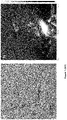
Figure 1 represents a) High resolution Transmission Electron Microscopy (HR-TEM) image of Ni@NC catalyst of example 1. b) Atomic Force Microscopy image of Ni@NC catalyst of example 1. c) Height profile for the Ni@NC catalyst of example 1. -
Figure 2 represents HRTEM Elemental mapping of carbon (a), nitrogen (b), nickel (c) and their superposition (d) forNi@NC catalyst compound 1. Scale bar: 2 µm. -
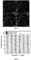
Figure 3 represents the Faradaic efficiency in function of the potential (V vs. RHE) for thecatalyst compound 1 thecatalyst compound 1 and Ni-NP@NC measured in CO2 saturated electrolyte. -
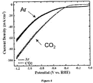
Figure 4 represents a linear sweep voltammetry forcatalyst compound 1 Ni@NC in argon and CO2 saturated electrolytes measured in the flow reactor. -
Figure 5 represents a) a linear sweep voltammetry for thecatalyst compound 1 Ni@NC measured in H cell (diamond) and flow reactor (square). Insert is the flow cell reactor and b) the Faradaic efficiency for Ni@NC operating in a flow reactor with flow rates of 60 mL min-1 for both CO2 and the electrolyte. -
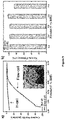
Figure 6 represents a,b) the evolution of the current density of CO and H2 from thecatalyst compound 1 Ni@NC with the flow rates of CO2 and electrolyte and c,d) the evolution of the Faradaic efficiency of CO and H2 from Ni@NC with the flow rates of CO2 and the electrolyte. -
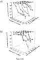
Figure 7 represents a) the 2D map of the CO2-to-CO conversion percentage from thecatalyst compound 1 Ni@NC with different CO2 flow rates and constant electrolyte flow rate of 60 mL/min, and b) the evolution of the CO2-to-CO conversion percentage with 1, 2 and 3 flow reactors connected in series. The geometrical area of the electrodes in the flow reactor is 1 cm2. - Nitrogen-rich carbon nanosheets with inclusion of nickel atoms (called here after Ni@NC) was prepared by mixing the organic precursor with nickel ions (Ni(NO3)2, CAS: 13478-00-7) and NaCl (CAS: 7647-14-5) crystals. The crystal grains (of various size from 0.1 to 1 µm) of NaCl act as template and enable a surface-limited limited growth of the catalysts on their surface. The organic molecules (in this example 2-methylimidazole, CAS: 693-98-1) coordinated with the Ni2+ ions in a similar way as for metal organic frameworks (MOFs). The quantity of NaCl loaded with Ni-coordinated 2-methylimidazole can currently be scaled up to 1 kg at this stage of the development. 2.5 g of Ni(NO3)2·6H2O and 10 g of 2-methylimidazol were dissolved in 125 mL of methanol. Then the two solutions were added into a flask followed by addition of 1 kg of NaCl powder under vigorous magnetic stirring for 10 h at room temperature. After slowly evaporating the methanol solvent at 35 °C, the powder was subjected to annealing at 800 °C under inert atmosphere (typically argon or nitrogen). After pyrolysis at T = 800 °C the organic molecules graphitize to form carbon nanosheets on the NaCl crystals. The material is then dissolved in water and treated with sulfuric acid for 12 hours at a concentration of 0.5 mol.L-1 sulfuric acid is used to leach out the Ni particles while preserving the single atoms that are strongly bounded to the carbon nanosheets.
- HR-TEM analyses confirmed the two dimensional morphology of the electrocatalytic materials similar to graphene nanosheets (
Figure 1a ). Atomic force microscopy (AFM) was used to measure the thickness of the nanosheets (Figure 1b ). As seen fromFigure 1c , the thickness of the nanosheets is estimated to be about 3 nm. The composition of the carbon nanosheets was analysed using X-ray photoelectron spectroscopy and elemental mapping under transmission electron microscope (TEM). - The elemental mapping of N, C, Ni is shown in
Figure 2a-d . No obvious aggregation of the nitrogen and nickel atoms can be observed. This strongly supports the presence of individual Ni atoms on the nitrogen-rich carbon nanosheets. The presence of N-C bonds as well as Ni was confirmed by XPS measurements and the total amount of Ni and nitrogen can be tuned from 2 to 8 at.% and 5 to 15 at.% (Table 1):
Thecatalyst compound 1 elemental analysis is compiled in table 1 below:Table 1: Elemental analysis of catalyst compound 1Elemental composition at.% Nitrogen 8.9 Carbon 70.9 Nickel 4.0 Oxygen 16.2 - In summary, the
catalyst compound 1 is a nitrogen rich carbon nanosheets with the inclusion of Ni in the form of ultra-small atomic clusters. - The
Ni@CN catalyst compound 1 was tested in a traditional "H-cell" reactor in a 0.5 M KOH saturated with argon and CO2 (Figure 3a ). In presence of CO2-saturated electrolyte, the reactivity of the Ni@CN is found to be much larger than in the case of argon-saturated electrolyte suggesting a high selectivity and activity towards the conversion of CO2 (Figure 4 ). The gas products were then detected using gas chromatography after 30 min operation in CO2 saturated electrolyte solution. - Only two gaseous products can be detected when using Ni@CN catalyst compound 1: H2 from the electrolysis of water and CO from the reduction of CO2.
- No other liquid products were detected from the analysis of the electrolyte solution (
Figure 3b ). - This result indicates a high selectivity, which is close to 100%, towards gaseous products of the
catalyst compound 1. - Next, the
catalyst compound 1 was compared with a catalyst consisting of Ni nanoparticles supported on nitrogen rich carbon nanosheets (Ni-NP@NC). Ni-NP@NC exhibits a low efficiency towards the production of CO and > 95% of the reaction products consist in hydrogen (H2) from the hydrolysis of water (Figure 3b ). - The results clearly demonstrate a dramatic improvement of the CO2 reduction reaction performance when using Ni in the form of individual atoms compared to nanoparticles.
- The
catalyst compound 1 was implemented into a flow reactor in order to obtain a so called 3-phase reaction that allows performing the reaction of the interface between the liquid electrolyte, the CO2 gas and the solid electrode (Inset:Figure 5a ). TheNi@NC catalyst compound 1 was deposited on a commercial gas diffusion electrode and the same CO2-saturated electrolyte was used as for the H cell reactor. - A larger current density was observed after saturating with CO2, indicating a clear selectivity towards the reduction of CO2 (
Figure 4 ). Importantly, the use of a flow reactor allows performing the reaction continuously while the chemical products can be directly analysed downstream the reactor using an in-line gas chromatography set-up. - A dramatic improvement of the current is observed and the current density increases from approx. 10 mA.cm-2 up to > 100 mA.cm-2 (
Figure 5a ). More importantly, the Faradaic efficiency towards CO is also improved and reaches 95-100 % for all potentials between -0.3 and -1.2 V vs. RHE (Figure 5b ). - The increase of the current density and the Faradaic efficiency reveals faster kinetics of the reaction and superior selectivity toward the production of CO compared to H2 from the water splitting reaction. The influence of two important parameters was then analysed in the flow reactor: the flow of CO2 and electrolyte in the reactor.
- The flow of electrolyte and CO2 gas was varied from 20 up to 100 mL.min-1 and 40 to 140 mL.min-1 respectively. The current density and the Faradaic efficiency were measured for each condition and at different potentials (
Figure 6a-d ). This allowed to map the behaviour of the reactor and it was found that a current density larger than 160 mA.cm-2 with a selectivity of about 100 % towards CO is achieved with a CO2 flow of 100 mL.min-1 and an electrolyte flow of 60 mL.min-1 (Figure 6a ). The in-line gas chromatography analyses allowed to estimate the reaction yield over 1 cm2 corresponding to the total exposed surface of the catalyst compounds 1 (Figure 6b ). - Using the optimal parameters, the CO2-to-CO conversion efficiency can reach 3 % over 1 cm2 and CO yield reach 14.05 mL/min/cm2 per mg of
catalyst compound 1. These results thus demonstrate a continuous conversion of 3 % of the CO2 over 1 cm2 (Figure 7a ). When connecting 3 cells of 1 cm2 in series, the conversion efficiency increases up to 10 % (Figure 7b ), which means that theNi@NC catalyst compound 1 can be used in flow reactors connected in series for increasing the conversion efficiency. -
- [1] J. Mater. Chem. A, 2020,8, 15012-15022
- [2] Energy Environ. Sci., 2019, 12, 149-156
Claims (11)
- A catalyst compound comprising nitrogen-rich carbon nanosheets and nickel atoms wherein the nickel atoms are coordinated with X atoms of nitrogen, X being comprised in the range from 3 to 4, supported on the carbon nanosheet.
- The compound according to claim 1 wherein the carbon nanosheets have a thickness of less than 5 nm, preferably 3 nm.
- The compound according to any of preceding claims, comprising from 2 to 8 at.% of nickel atoms, preferably from 3 to 5 at.%.
- The compound according to any of preceding claims, comprising from 5 to 15 at.% of nitrogen atoms, preferably from 7 to 12 at.%.
- The compound according to any of preceding claims, wherein the compound is in the form of ultra-small atomic clusters of nickel supported on nitrogen-doped carbon nanosheets.
- Use of the compound according to any of preceding claims as a catalyst, preferably to reduce CO2 into CO.
- A process of manufacture of catalyst compound comprising a nitrogen-rich carbon nanosheets and nickel atoms comprising the steps of:a) mixing, in a solvent, an organic precursor with a nickel ions precursor and NaCl crystals,b) pyrolysis of the mixture obtained in step a), preferably at a temperature from 700°C to 1000°C,
wherein the organic precursor is an organic molecule comprising at least one nitrogen atom. - The process according to preceding claim, wherein the organic molecule is chosen in the group of organic molecules bearing a moiety chosen in the group comprising methylimidazole, dicyanamide and dicyandiamide moieties.
- The process according to claim 7 or 8, further comprising a step c) of treating under acidic condition the compound obtained in step b).
- A process of reduction of CO2 into CO comprising a step of contacting CO2 (gas) with a catalyst compound (solid) according to any of preceding claims.
- The process according to preceding claim, wherein the reduction reaction of CO2 is done under atmospheric pressure and at room temperature.
Priority Applications (1)
| Application Number | Priority Date | Filing Date | Title |
|---|---|---|---|
| EP20306325.0A EP3995603A1 (en) | 2020-11-04 | 2020-11-04 | Electrocatalytic material comprising nitrogen-rich carbon nanosheets with inclusions of metal atoms and use thereof |
Applications Claiming Priority (1)
| Application Number | Priority Date | Filing Date | Title |
|---|---|---|---|
| EP20306325.0A EP3995603A1 (en) | 2020-11-04 | 2020-11-04 | Electrocatalytic material comprising nitrogen-rich carbon nanosheets with inclusions of metal atoms and use thereof |
Publications (1)
| Publication Number | Publication Date |
|---|---|
| EP3995603A1 true EP3995603A1 (en) | 2022-05-11 |
Family
ID=73598020
Family Applications (1)
| Application Number | Title | Priority Date | Filing Date |
|---|---|---|---|
| EP20306325.0A Withdrawn EP3995603A1 (en) | 2020-11-04 | 2020-11-04 | Electrocatalytic material comprising nitrogen-rich carbon nanosheets with inclusions of metal atoms and use thereof |
Country Status (1)
| Country | Link |
|---|---|
| EP (1) | EP3995603A1 (en) |
Cited By (2)
| Publication number | Priority date | Publication date | Assignee | Title |
|---|---|---|---|---|
| CN115323421A (en) * | 2022-08-29 | 2022-11-11 | 安徽工业大学 | Preparation and application of nickel oxide cluster modified nickel-nitrogen-carbon single-atom catalyst |
| CN115386906A (en) * | 2022-07-29 | 2022-11-25 | 华东理工大学 | Carbon-supported nickel monoatomic catalyst and preparation method and application thereof |
Citations (3)
| Publication number | Priority date | Publication date | Assignee | Title |
|---|---|---|---|---|
| US20180044805A1 (en) * | 2015-02-16 | 2018-02-15 | Stc.Unm | Materials with Atomically Dispersed Chemical Moieties |
| WO2018195045A1 (en) * | 2017-04-17 | 2018-10-25 | President And Fellows Of Harvard College | Metal-doped catalyst, methods for its production and uses thereof |
| CN110961134A (en) * | 2019-11-28 | 2020-04-07 | 华南理工大学 | Method for synthesizing monatomic catalyst, monatomic catalyst and application |
-
2020
- 2020-11-04 EP EP20306325.0A patent/EP3995603A1/en not_active Withdrawn
Patent Citations (3)
| Publication number | Priority date | Publication date | Assignee | Title |
|---|---|---|---|---|
| US20180044805A1 (en) * | 2015-02-16 | 2018-02-15 | Stc.Unm | Materials with Atomically Dispersed Chemical Moieties |
| WO2018195045A1 (en) * | 2017-04-17 | 2018-10-25 | President And Fellows Of Harvard College | Metal-doped catalyst, methods for its production and uses thereof |
| CN110961134A (en) * | 2019-11-28 | 2020-04-07 | 华南理工大学 | Method for synthesizing monatomic catalyst, monatomic catalyst and application |
Non-Patent Citations (10)
| Title |
|---|
| CAI ZHEWEI ET AL: "Single-atom-sized Ni-N 4 sites anchored in three-dimensional hierarchical carbon nanostructures for the oxygen reduction reaction", JOURNAL OF MATERIALS CHEMISTRY A, vol. 8, no. 30, 1 January 2020 (2020-01-01), GB, pages 15012 - 15022, XP055784188, ISSN: 2050-7488, DOI: 10.1039/D0TA05326K * |
| CUI XIAOJU ET AL: "A Graphene Composite Material with Single Cobalt Active Sites: A Highly Efficient Counter Electrode for Dye-Sensitized Solar Cells", ANGEWANDTE CHEMIE INTERNATIONAL EDITION, vol. 55, no. 23, 18 April 2016 (2016-04-18), pages 6708 - 6712, XP055784525, ISSN: 1433-7851, DOI: 10.1002/anie.201602097 * |
| DENG DEHUI ET AL: "A single iron site confined in a graphene matrix for the catalytic oxidation of benzene at room temperature", SCIENCE ADVANCES, vol. 1, no. 11, 1 December 2015 (2015-12-01), pages e1500462, XP055784626, DOI: 10.1126/sciadv.1500462 * |
| EFFICIENT ALKALINE HYDROGEN EVOLUTION ON ATOMICALLY DISPERSED NI-NX SPECIES ANCHORED POROUS CARBON WITH EMBEDDED NI NANOPARTICLES BY ACCELERATING WATER DISSOCIATION KINETICS |
| ENERGY ENVIRON. SCI., vol. 12, 2019, pages 149 - 156 |
| J. MATER. CHEM. A, vol. 8, 2020, pages 15012 - 15022 |
| JIANG KUN ET AL: "Isolated Ni single atoms in graphene nanosheets for high-performance CO 2 reduction", ENERGY & ENVIRONMENTAL SCIENCE, vol. 11, no. 4, 1 January 2018 (2018-01-01), Cambridge, pages 893 - 903, XP055784207, ISSN: 1754-5692, DOI: 10.1039/C7EE03245E * |
| LEI CHAOJUN ET AL: "Efficient alkaline hydrogen evolution on atomically dispersed Ni-N x Species anchored porous carbon with embedded Ni nanoparticles by accelerating water dissociation kinetics", ENERGY & ENVIRONMENTAL SCIENCE, vol. 12, no. 1, 1 January 2019 (2019-01-01), Cambridge, pages 149 - 156, XP055784191, ISSN: 1754-5692, DOI: 10.1039/C8EE01841C * |
| SINGLE-ATOM-SIZED NI-N4 SITES ANCHORED IN THREE-DIMENSIONAL HIERARCHICAL CARBON NANOSTRUCTURES FOR THE OXYGEN REDUCTION REACTION |
| XU YINGQI ET AL: "A general bimetal-ion adsorption strategy to prepare nickel single atom catalysts anchored on graphene for efficient oxygen evolution reaction", JOURNAL OF ENERGY CHEMISTRY, ELSEVIER, AMSTERDAM, NL, vol. 43, 20 August 2019 (2019-08-20), pages 52 - 57, XP085926306, ISSN: 2095-4956, DOI: 10.1016/J.JECHEM.2019.08.006 * |
Cited By (2)
| Publication number | Priority date | Publication date | Assignee | Title |
|---|---|---|---|---|
| CN115386906A (en) * | 2022-07-29 | 2022-11-25 | 华东理工大学 | Carbon-supported nickel monoatomic catalyst and preparation method and application thereof |
| CN115323421A (en) * | 2022-08-29 | 2022-11-11 | 安徽工业大学 | Preparation and application of nickel oxide cluster modified nickel-nitrogen-carbon single-atom catalyst |
Similar Documents
| Publication | Publication Date | Title |
|---|---|---|
| Chang et al. | Copper-based catalysts for electrochemical carbon dioxide reduction to multicarbon products | |
| Qin et al. | Ru/Ir‐based electrocatalysts for oxygen evolution reaction in acidic conditions: from mechanisms, optimizations to challenges | |
| Liu et al. | Stable nanoporous Sn/SnO2 composites for efficient electroreduction of CO2 to formate over wide potential range | |
| Wang et al. | Novel flower-like PdAu (Cu) anchoring on a 3D rGO-CNT sandwich-stacked framework for highly efficient methanol and ethanol electro-oxidation | |
| Zhang et al. | Nanostructured materials for heterogeneous electrocatalytic CO2 reduction and their related reaction mechanisms | |
| Liu et al. | CO 2 electoreduction reaction on heteroatom-doped carbon cathode materials | |
| Liu et al. | Facile synthesis of NiS2 nanowires and its efficient electrocatalytic performance for hydrogen evolution reaction | |
| US10844501B2 (en) | Carbon supported single atom carbon dioxide reduction electro catalysts | |
| Lu et al. | Facile one-step aqueous-phase synthesis of porous PtBi nanosponges for efficient electrochemical methanol oxidation with a high CO tolerance | |
| Mou et al. | Enhanced electrochemical reduction of carbon dioxide to formate with in-situ grown indium-based catalysts in an aqueous electrolyte | |
| Zhang et al. | PtBi intermetallic and PtBi intermetallic with the Bi-rich surface supported on porous graphitic carbon towards HCOOH electro-oxidation | |
| Liu et al. | Isolated ultrasmall Bi nanosheets for efficient CO2-to-formate electroreduction | |
| CN109626368B (en) | A kind of N-doped γ-type graphityne carbon material and its preparation method and application | |
| Kakati et al. | Core shell like behavior of PdMo nanoparticles on multiwall carbon nanotubes and their methanol oxidation activity in alkaline medium | |
| Zhang et al. | Hollow nanoporous Au/Pt core–shell catalysts with nanochannels and enhanced activities towards electro-oxidation of methanol and ethanol | |
| Luo et al. | Palladium-based nanoelectrocatalysts for renewable energy generation and conversion | |
| Yang et al. | Pd nanoparticles supported on phenanthroline modified carbon as high active electrocatalyst for ethylene glycol oxidation | |
| Wu et al. | Indium doped bismuth subcarbonate nanosheets for efficient electrochemical reduction of carbon dioxide to formate in a wide potential window | |
| Wang et al. | Nanochain-structured mesoporous tungsten carbide and its superior electrocatalysis | |
| Zhang et al. | Emerging interstitial/substitutional modification of Pd-based nanomaterials with nonmetallic elements for electrocatalytic applications | |
| Wang et al. | Ionic liquid derived Fe, N, B co-doped bamboo-like carbon nanotubes as an efficient oxygen reduction catalyst | |
| Wang et al. | Heterointerface engineering of Rh/Pd metallene for hydrazine oxidation-assisted energy-saving hydrogen production | |
| Wang et al. | Hydrogen-intercalation PdZn bimetallene for urea electro-synthesis from nitrate and carbon dioxide | |
| Ávila-Bolívar et al. | On the activity and stability of Sb2O3/Sb nanoparticles for the electroreduction of CO2 toward formate | |
| Sun et al. | PtRhCu ternary alloy nanodendrites with enhanced catalytic activity and durability toward methanol electro-oxidation |
Legal Events
| Date | Code | Title | Description |
|---|---|---|---|
| PUAI | Public reference made under article 153(3) epc to a published international application that has entered the european phase |
Free format text: ORIGINAL CODE: 0009012 |
|
| STAA | Information on the status of an ep patent application or granted ep patent |
Free format text: STATUS: THE APPLICATION HAS BEEN PUBLISHED |
|
| AK | Designated contracting states |
Kind code of ref document: A1 Designated state(s): AL AT BE BG CH CY CZ DE DK EE ES FI FR GB GR HR HU IE IS IT LI LT LU LV MC MK MT NL NO PL PT RO RS SE SI SK SM TR |
|
| STAA | Information on the status of an ep patent application or granted ep patent |
Free format text: STATUS: THE APPLICATION IS DEEMED TO BE WITHDRAWN |
|
| 18D | Application deemed to be withdrawn |
Effective date: 20221112 |