EP3995268A1 - Tactile sensor, tactile sensor system, and program - Google Patents
Tactile sensor, tactile sensor system, and program Download PDFInfo
- Publication number
- EP3995268A1 EP3995268A1 EP19936205.4A EP19936205A EP3995268A1 EP 3995268 A1 EP3995268 A1 EP 3995268A1 EP 19936205 A EP19936205 A EP 19936205A EP 3995268 A1 EP3995268 A1 EP 3995268A1
- Authority
- EP
- European Patent Office
- Prior art keywords
- unit
- imaging
- image
- transmitting unit
- tactile sensor
- Prior art date
- Legal status (The legal status is an assumption and is not a legal conclusion. Google has not performed a legal analysis and makes no representation as to the accuracy of the status listed.)
- Pending
Links
Images




Classifications
-
- G—PHYSICS
- G06—COMPUTING OR CALCULATING; COUNTING
- G06T—IMAGE DATA PROCESSING OR GENERATION, IN GENERAL
- G06T1/00—General purpose image data processing
- G06T1/0014—Image feed-back for automatic industrial control, e.g. robot with camera
-
- B—PERFORMING OPERATIONS; TRANSPORTING
- B25—HAND TOOLS; PORTABLE POWER-DRIVEN TOOLS; MANIPULATORS
- B25J—MANIPULATORS; CHAMBERS PROVIDED WITH MANIPULATION DEVICES
- B25J13/00—Controls for manipulators
- B25J13/08—Controls for manipulators by means of sensing devices, e.g. viewing or touching devices
- B25J13/081—Touching devices, e.g. pressure-sensitive
- B25J13/082—Grasping-force detectors
- B25J13/083—Grasping-force detectors fitted with slippage detectors
-
- B—PERFORMING OPERATIONS; TRANSPORTING
- B25—HAND TOOLS; PORTABLE POWER-DRIVEN TOOLS; MANIPULATORS
- B25J—MANIPULATORS; CHAMBERS PROVIDED WITH MANIPULATION DEVICES
- B25J19/00—Accessories fitted to manipulators, e.g. for monitoring, for viewing; Safety devices combined with or specially adapted for use in connection with manipulators
- B25J19/02—Sensing devices
- B25J19/021—Optical sensing devices
-
- G—PHYSICS
- G06—COMPUTING OR CALCULATING; COUNTING
- G06V—IMAGE OR VIDEO RECOGNITION OR UNDERSTANDING
- G06V10/00—Arrangements for image or video recognition or understanding
- G06V10/10—Image acquisition
- G06V10/12—Details of acquisition arrangements; Constructional details thereof
- G06V10/14—Optical characteristics of the device performing the acquisition or on the illumination arrangements
-
- B—PERFORMING OPERATIONS; TRANSPORTING
- B25—HAND TOOLS; PORTABLE POWER-DRIVEN TOOLS; MANIPULATORS
- B25J—MANIPULATORS; CHAMBERS PROVIDED WITH MANIPULATION DEVICES
- B25J13/00—Controls for manipulators
- B25J13/08—Controls for manipulators by means of sensing devices, e.g. viewing or touching devices
- B25J13/081—Touching devices, e.g. pressure-sensitive
- B25J13/084—Tactile sensors
-
- B—PERFORMING OPERATIONS; TRANSPORTING
- B25—HAND TOOLS; PORTABLE POWER-DRIVEN TOOLS; MANIPULATORS
- B25J—MANIPULATORS; CHAMBERS PROVIDED WITH MANIPULATION DEVICES
- B25J9/00—Program-controlled manipulators
- B25J9/16—Program controls
- B25J9/1602—Program controls characterised by the control system, structure, architecture
-
- B—PERFORMING OPERATIONS; TRANSPORTING
- B25—HAND TOOLS; PORTABLE POWER-DRIVEN TOOLS; MANIPULATORS
- B25J—MANIPULATORS; CHAMBERS PROVIDED WITH MANIPULATION DEVICES
- B25J9/00—Program-controlled manipulators
- B25J9/16—Program controls
- B25J9/1694—Program controls characterised by use of sensors other than normal servo-feedback from position, speed or acceleration sensors, perception control, multi-sensor controlled systems, sensor fusion
- B25J9/1697—Vision controlled systems
-
- G—PHYSICS
- G01—MEASURING; TESTING
- G01B—MEASURING LENGTH, THICKNESS OR SIMILAR LINEAR DIMENSIONS; MEASURING ANGLES; MEASURING AREAS; MEASURING IRREGULARITIES OF SURFACES OR CONTOURS
- G01B11/00—Measuring arrangements characterised by the use of optical techniques
- G01B11/02—Measuring arrangements characterised by the use of optical techniques for measuring length, width or thickness
-
- G—PHYSICS
- G01—MEASURING; TESTING
- G01B—MEASURING LENGTH, THICKNESS OR SIMILAR LINEAR DIMENSIONS; MEASURING ANGLES; MEASURING AREAS; MEASURING IRREGULARITIES OF SURFACES OR CONTOURS
- G01B11/00—Measuring arrangements characterised by the use of optical techniques
- G01B11/16—Measuring arrangements characterised by the use of optical techniques for measuring the deformation in a solid, e.g. optical strain gauge
-
- G—PHYSICS
- G06—COMPUTING OR CALCULATING; COUNTING
- G06T—IMAGE DATA PROCESSING OR GENERATION, IN GENERAL
- G06T7/00—Image analysis
- G06T7/0002—Inspection of images, e.g. flaw detection
- G06T7/0004—Industrial image inspection
- G06T7/001—Industrial image inspection using an image reference approach
-
- G—PHYSICS
- G06—COMPUTING OR CALCULATING; COUNTING
- G06V—IMAGE OR VIDEO RECOGNITION OR UNDERSTANDING
- G06V10/00—Arrangements for image or video recognition or understanding
- G06V10/10—Image acquisition
- G06V10/12—Details of acquisition arrangements; Constructional details thereof
- G06V10/14—Optical characteristics of the device performing the acquisition or on the illumination arrangements
- G06V10/141—Control of illumination
-
- G—PHYSICS
- G06—COMPUTING OR CALCULATING; COUNTING
- G06V—IMAGE OR VIDEO RECOGNITION OR UNDERSTANDING
- G06V10/00—Arrangements for image or video recognition or understanding
- G06V10/20—Image preprocessing
- G06V10/22—Image preprocessing by selection of a specific region containing or referencing a pattern; Locating or processing of specific regions to guide the detection or recognition
-
- G—PHYSICS
- G06—COMPUTING OR CALCULATING; COUNTING
- G06V—IMAGE OR VIDEO RECOGNITION OR UNDERSTANDING
- G06V20/00—Scenes; Scene-specific elements
- G06V20/50—Context or environment of the image
-
- G—PHYSICS
- G01—MEASURING; TESTING
- G01B—MEASURING LENGTH, THICKNESS OR SIMILAR LINEAR DIMENSIONS; MEASURING ANGLES; MEASURING AREAS; MEASURING IRREGULARITIES OF SURFACES OR CONTOURS
- G01B11/00—Measuring arrangements characterised by the use of optical techniques
- G01B11/16—Measuring arrangements characterised by the use of optical techniques for measuring the deformation in a solid, e.g. optical strain gauge
- G01B11/165—Measuring arrangements characterised by the use of optical techniques for measuring the deformation in a solid, e.g. optical strain gauge by means of a grating deformed by the object
-
- G—PHYSICS
- G06—COMPUTING OR CALCULATING; COUNTING
- G06T—IMAGE DATA PROCESSING OR GENERATION, IN GENERAL
- G06T2207/00—Indexing scheme for image analysis or image enhancement
- G06T2207/30—Subject of image; Context of image processing
- G06T2207/30108—Industrial image inspection
-
- G—PHYSICS
- G06—COMPUTING OR CALCULATING; COUNTING
- G06T—IMAGE DATA PROCESSING OR GENERATION, IN GENERAL
- G06T2207/00—Indexing scheme for image analysis or image enhancement
- G06T2207/30—Subject of image; Context of image processing
- G06T2207/30204—Marker
Definitions
- the present invention relates to a tactile sensor, a tactile sensor system, and a program.
- a method for detecting an object abutting on an outer surface of a rubber skin is known as a method for implementing a tactile sensor (for example, see PTL 1).
- an imaging optical axis of an imaging unit is provided parallel to a normal line direction of the rubber skin (hereinafter, referred to as an abutting surface).
- the imaging unit detects a gripping state of the object by imaging the abutting surface and detecting a displacement of the abutting surface when the object abuts on the abutting surface.
- a size of the tactile sensor may be small, for example, when an object to be tactually sensed is small. Considering miniaturization of the tactile sensor, it is a problem to shorten a distance between the imaging unit that images the object and the abutting surface, and to miniaturize the imaging unit.
- the invention is made in view of such a situation, and an object of the invention is to provide a tactile sensor that can be easily miniaturized, a tactile sensor system, and a program.
- a tactile sensor includes a transmitting unit including a first surface that is capable of coming into contact with a gripping target object and a second surface that is a back surface of the first surface, an imaging unit that is capable of imaging an image of an object present on a first surface side of the transmitting unit from a second surface side, and a reflecting unit arranged on the second surface side of the transmitting unit and configured to reflect light from at least a part of a region of the transmitting unit and guide the light into an imaging view angle of the imaging unit.
- the transmitting unit deforms along a shape of the gripping target object that is in contact with the first surface
- the imaging unit is capable of imaging an image of the object present on the first surface side and images of markers attached to the transmitting unit from the second surface side, the markers indicating a deformation of the transmitting unit.
- the imaging unit is arranged such that an imaging optical axis of the imaging unit and a normal line of the second surface of the transmitting unit have an intersection.
- the reflecting unit includes a plurality of reflecting surfaces having different normal line angles with respect to an imaging optical axis of the imaging unit.
- the imaging unit images both a first image that is an image of an imaging target region of the transmitting unit formed by light incident without passing through the reflecting unit, and a second image that is an image of the imaging target region of the transmitting unit formed by light reflected by the reflecting unit and then incident on the imaging unit, as images of the transmitting unit.
- the transmitting unit includes a plurality of regions having different normal line angles with respect to an imaging optical axis of the imaging unit, and the imaging unit is capable of imaging an image of the object present on the first surface side formed by light incident through each of the plurality of regions of the transmitting unit.
- a tactile sensor system includes the above tactile sensor, and a detecting unit configured to acquire the image imaged by the imaging unit and detect a contact state of an object with respect to the first surface based on the acquired image.
- a program causes a computer connected to a tactile sensor to execute an image acquisition step of acquiring an image imaged by an imaging unit, and a detection step of detecting a contact state of an object with respect to a first surface based on the image acquired in the image acquisition step.
- the tactile sensor includes a transmitting unit including the first surface that is capable of coming into contact with a gripping target object and a second surface that is a back surface of the first surface, an imaging unit that is capable of imaging an image of an object present on a first surface side of the transmitting unit from a second surface side, and a reflecting unit arranged on the second surface side of the transmitting unit and configured to reflect light from at least a part of a region of the transmitting unit and guide the light into an imaging view angle of the imaging unit.
- FIG. 1 shows an example of a robot system 100 according to an embodiment.
- the robot system 100 in the present embodiment grips a gripping target object while detecting a gripping state by coming into contact with the gripping target object.
- the robot system 100 includes a tactile sensor module 10, a robot system control unit 90, a tip portion 110, an upper arm portion 120, a joint portion 130, a lower arm portion 140, a main horizontal shaft portion 150, a main vertical shaft portion 160, and a base portion 170.
- the base portion 170 is a portion connected to the main vertical shaft portion 160.
- the main vertical shaft portion 160 is a portion connecting the main horizontal shaft portion 150 and the base portion 170.
- the main vertical shaft portion 160 is controlled by the robot system control unit 90, and displaces the main horizontal shaft portion 150 around a shaft of the main vertical shaft portion 160.
- the main horizontal shaft portion 150 is a portion connecting the lower arm portion 140 and the main vertical shaft portion 160.
- the main horizontal shaft portion 150 is controlled by the robot system control unit 90, and displaces the lower arm portion 140 around a shaft of the main horizontal shaft portion 150.
- the lower arm portion 140 is a portion connecting the joint portion 130 and the main horizontal shaft portion 150.
- the joint portion 130 is a portion connecting the upper arm portion 120 and the lower arm portion 140.
- the joint portion 130 is controlled by the robot system control unit 90, and displaces the upper arm portion 120 around a shaft of the joint portion 130.
- the upper arm portion 120 is a portion connecting the tip portion 110 and the joint portion 130.
- the tip portion 110 is connected to the tactile sensor module 10.
- a posture (for example, position and direction) of the tip portion 110 is controlled by the robot system control unit 90.
- the posture of the tactile sensor module 10 changes as the posture of the tip portion 110 changes.
- the tactile sensor module 10 detects a contact state of the gripping target object, and outputs information indicating the detected contact state of the gripping target object to the robot system control unit 90.
- the robot system control unit 90 acquires the information output by the tactile sensor module 10.
- the robot system control unit 90 moves the tactile sensor module 10 by displacing the portions included in the robot system 100 (the tip portion 110, the upper arm portion 120, the joint portion 130, the lower arm portion 140, the main horizontal shaft portion 150, and the main vertical shaft portion 160) by a driving device (not shown).
- the robot system control unit 90 controls the robot system 100 based on the information acquired from the tactile sensor module 10.
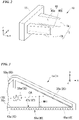
- FIG. 2 shows an example of the tactile sensor module 10 according to the embodiment.
- the tactile sensor module 10 according to the present embodiment includes a sensor connecting portion 11, a first tactile sensor 1a, and a second tactile sensor 1b.
- the posture of the tactile sensor module 10 may be shown by a three-dimensional orthogonal coordinate system of an x-axis, a y-axis, and a z-axis.
- the sensor connecting portion 11 is a portion connecting the tip portion 110 and the first tactile sensor 1a and the second tactile sensor 1b.
- the first tactile sensor 1a is connected to the sensor connecting portion 11.
- the first tactile sensor 1a includes a first transmitting unit contact surface 40a.
- the second tactile sensor 1b is connected to the sensor connecting portion 11.
- the second tactile sensor 1b includes a second transmitting unit contact surface 40b.
- the first tactile sensor 1a and the second tactile sensor 1b are arranged such that the first transmitting unit contact surface 40a and the second transmitting unit contact surface 40b face each other.
- the sensor connecting portion 11 includes a driving device (not shown), and displaces the first tactile sensor 1a and the second tactile sensor 1b (or one of those sensors; the same applies to the following description.) in a y-axis direction based on an instruction from the robot system control unit 90.
- the tactile sensor module 10 grips a gripping target object between the first tactile sensor 1a and the second tactile sensor 1b by driving the first tactile sensor 1a and the second tactile sensor 1b in the y-axis direction.
- FIG. 3 shows an example of a cross-sectional view of a tactile sensor according to the embodiment.
- FIG. 3 shows a cross-sectional view of the first tactile sensor 1a shown in FIG. 2 on an x-y plane.
- the direction of the tactile sensor module 10 is indicated by the three-dimensional orthogonal coordinate system of the x-axis, the y-axis, and the z-axis.
- first tactile sensor 1a and the second tactile sensor 1b have the same configuration, the first tactile sensor 1a will be described, and the description of the second tactile sensor 1b will be omitted.
- the first tactile sensor 1a includes a first imaging unit 30a, a first reflecting unit 20a, a transmitting unit 43a, first markers 45a, the first transmitting unit contact surface 40a, a first transmitting unit non-contact surface 47a, a first rigid layer 70a, and a first frame 50a.
- the first imaging unit 30a will be referred to as an imaging unit 30, the first reflecting unit 20a will be referred to as a reflecting unit 20, the first transmitting unit 43a will be referred to as a transmitting unit 43, the first markers 45a will be referred to as markers 45, the first transmitting unit contact surface 40a will be referred to as a transmitting unit contact surface 40, the first transmitting unit non-contact surface 47a will be referred to as a transmitting unit non-contact surface 47, the first rigid layer 70a will be referred to as a rigid layer 70, and the first frame 50a will be referred to as a frame 50, respectively.
- the frame 50 holds the imaging unit 30, the reflecting unit 20, the transmitting unit 43, and the rigid layer 70.
- the transmitting unit 43 is made of a transparent material that transmits light, and includes the transmitting unit contact surface 40 and the transmitting unit non-contact surface 47.
- a specific material of the transmitting unit 43 may be a silicone material having a thickness of 2 mm and a transmittance of about 94%.
- the transmitting unit contact surface 40 is a surface capable of coming into contact with the gripping target object of a front surface and a back surface of the transmitting unit 43.
- the transmitting unit non-contact surface 47 is a surface that does not come into contact with the gripping target object of the front surface and the back surface of the transmitting unit 43.
- the surface that is capable of coming into contact with the gripping target object (that is, the transmitting unit contact surface 40) is also referred to as the front surface or a first surface
- the surface that does not come into contact with the gripping target object (that is, the transmitting unit non-contact surface 47) is also referred to as the back surface or a second surface
- the transmitting unit 43 includes the transmitting unit contact surface 40, which is a contact surface that is capable of coming into contact with the gripping target object, and the transmitting unit non-contact surface 47, which is the back surface of the contact surface and is a non-contact surface that does not come into contact with the gripping target object.
- the transmitting unit 43 is made of a transparent material.
- at least a part of the transmitting unit 43 deforms along a shape of the gripping target object that is in contact with the transmitting unit contact surface 40, which is the contact surface.
- a plurality of markers 45 are arranged at predetermined positions of the transmitting unit 43.
- the markers 45 are opaque members arranged at positions of grid points separated at equal intervals inside the transmitting unit 43.
- the markers 45 are arranged inside the transmitting unit 43, but are not limited thereto, and may be provided on the transmitting unit contact surface 40 or on the transmitting unit non-contact surface 47.
- the markers 45 are described as being arranged discretely at the positions of the grid points, but are not limited thereto.
- the markers 45 may be a grid pattern or another continuous pattern.
- the pattern of the markers 45 may be an irregular pattern so that a gripping state of the gripping target object can be easily detected.
- the markers 45 are described as opaque members, but are not limited thereto, and the markers may be semi-transparent members or transparent members as long as the displacement when the gripping target object is in contact can be optically recognized.
- the rigid layer 70 is provided at a position in contact with the transmitting unit non-contact surface 47 of the transmitting unit 43.
- the rigid layer 70 is made of a transparent and rigid material such as acrylic. The rigid layer 70 limits a deformation amount of the transmitting unit 43 when the gripping target object is gripped.
- the transmitting unit 43 and the rigid layer 70 are described as separate components.
- the rigid layer 70 may be omitted as long as the deformation amount of the transmitting unit 43 when the gripping target object is gripped is within a predetermined range.
- the reflecting unit 20 includes a reflecting surface that reflects light, such as a mirror. This reflecting surface is arranged on a non-contact surface side of the transmitting unit 43. The reflecting unit 20 reflects light transmitted through the transmitting unit 43 and guides the reflected light to the imaging unit 30.
- the reflecting unit 20 reflects light from at least a part of a region of the transmitting unit 43. That is, the reflecting unit 20 is arranged on the non-contact surface side of the transmitting unit 43 (for example, the transmitting unit non-contact surface 47), and reflects the light from at least a part of the region of the transmitting unit 43 and guides the light into an imaging view angle of the imaging unit 30.
- the imaging unit 30 is arranged on a transmitting unit non-contact surface 47 side of the front surface and the back surface of the transmitting unit 43. More specifically, the imaging unit 30 is arranged such that an imaging optical axis OA of the imaging unit 30 and a normal line N41 of the transmitting unit non-contact surface 47 of the transmitting unit 43 have an intersection (the imaging optical axis OA and the normal line N41 are not parallel to each other).
- the imaging unit 30 images an image within the imaging view angle around the imaging optical axis OA, and outputs an imaging result as image information.
- the imaging unit 30 is capable of imaging the image of an object present on a transmitting unit contact surface 40 side of the transmitting unit 43 from the transmitting unit non-contact surface 47 side.
- light transmitted through the transmitting unit 43 includes the image of the object present on the transmitting unit contact surface 40 side of the transmitting unit 43.
- the light transmitted through the transmitting unit 43 further includes images of the markers 45 arranged on the transmitting unit 43 (that is, an image of the transmitting unit 43 or an image of the transmitting unit). That is, the imaging unit 30 is capable of imaging the image of the object present on the transmitting unit contact surface 40 side, which is a contact surface side of the transmitting unit 43, and the images of the markers that are attached to the transmitting unit 43 and indicate a deformation of the transmitting unit 43, from the transmitting unit non-contact surface 47 side, which is the non-contact surface side.
- an imageable range of the imaging unit 30 includes an image formed by light transmitted through the transmitting unit 43 and reflected by the reflecting unit 20 and an image formed by light that is transmitted through the transmitting unit 43 and directly reaches the imaging unit 30 without passing through the reflecting unit 20.
- the image formed by the light that is transmitted through the transmitting unit 43 and directly reaches the imaging unit 30 without passing through the reflecting unit 20 is also referred to as a direct image.
- the image formed by the light transmitted through the transmitting unit 43 and reflected by the reflecting unit 20 is also referred to as a reflected image.
- the imageable range of the imaging unit 30 will be described with reference to FIGS. 4 and 5 .
- FIG. 4 shows an example of the imageable range of the imaging unit 30 according to the embodiment.
- the imageable range of the imaging unit 30 included in the tactile sensor 1 will be described.
- the imageable range of the imaging unit 30 is determined by a geometric relative relation between a view angle A10 of the imaging unit 30 and an arrangement of the reflecting unit 20.
- the imageable range of the imaging unit 30 includes a region where the direct image can be imaged and a region where the reflected image can be imaged.
- an incident angle of light incident on the reflecting unit 20 from the transmitting unit contact surface 40 side is a first incident angle IA10
- the light incident on the reflecting unit 20 is emitted in the direction of a first reflecting angle RA10.
- the incident angle of the light incident on the reflecting unit 20 from the transmitting unit contact surface 40 side is a second incident angle IA20
- the light incident on the reflecting unit 20 is emitted in the direction of a second reflecting angle RA20.
- the incident angle of the light incident on the reflecting unit 20 from the transmitting unit contact surface 40 side is a third incident angle IA30
- the light incident on the reflecting unit 20 is emitted in the direction of a third reflecting angle RA30 (in this example, the imaging optical axis OA).
- the imaging unit 30 can image the light emitted from the reflecting unit 20.
- a first imaging range AR1 is a range in which the imaging unit 30 can image the direct image and cannot image the reflected image.
- a second imaging range AR2 is a range in which the imaging unit 30 can image both the direct image and the reflected image.
- a third imaging range AR3 is a range in which the imaging unit 30 cannot image the direct image and can image the reflected image.
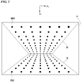
- FIG. 5 shows an example of an imaged image of the imaging unit 30 according to the embodiment.
- An imaged image P includes a direct view imaged image R and a reflected view imaged image M as image components.
- the imaged image P is shown by a two-dimensional orthogonal coordinate system of an x c -axis and a y c -axis.
- An x c y c plane shows an image plane on which a yz plane is imaged in FIG. 4 .
- Direct view imaging markers RM are images obtained by imaging direct images of the markers 45 by the imaging unit 30.
- Reflected view imaging markers MM are images obtained by imaging reflected images of the markers 45 by the imaging unit 30.
- a first object OB1 to a third object OB3 will be described as an example with reference to FIGS. 4 and 5 .
- the first object OB1 is present in the first imaging range AR1.
- the imaging unit 30 can image a direct image of the first object OB1 and cannot image a reflected image of the first object OB1.
- the second object OB2 is present in the second imaging range AR2.
- the imaging unit 30 can image a direct image and a reflected image of the second object OB2.
- the third object OB3 is present in the third imaging range AR3.
- the imaging unit 30 cannot image a direct image of the third object OB3 and can image a reflected image of the third object OB3.
- the imaging unit 30 images both a first image, which is the image of an imaging target region of the transmitting unit 43 formed by the light incident without passing through the reflecting unit 20, and a second image, which is the image of the imaging target region of the transmitting unit 43 formed by the light reflected by the reflecting unit 20 and then incident on the imaging unit 30, as images of the transmitting unit 43.
- the imaging unit 30 is capable of simultaneously imaging the direct view imaged image R and the reflected view imaged image M.
- FIG. 6 shows an example of a cross-sectional view of the tactile sensor when the gripping target object according to the embodiment is in contact with the contact surface.
- FIG. 6 shows an example of a cross-sectional view of the tactile sensor when the gripping target object according to the embodiment is in contact with the contact surface.
- the object OB4 which is the gripping target object, is in contact with the transmitting unit contact surface 40.
- a range in which the object OB4 is in contact with the transmitting unit contact surface 40 is defined as an object detection range ODA.
- the markers 45 in the object detection range ODA are displaced.
- the imaging unit 30 images the markers 45 in the object detection range ODA in time series.
- the object OB4 is present at a position that spans imaging ranges of both the second imaging range AR2 and the third imaging range AR3. Therefore, both a direct view and a reflected view are possible.
- FIG. 7 shows an example of the imaged image of the tactile sensor when the gripping target object according to the embodiment is in contact with the contact surface.
- the imaged image P includes the direct view imaged image R and the reflected view imaged image M as image components.
- FIG. 7 shows the imaged image P when the object OB4 is in contact with the transmitting unit contact surface 40.
- the direct view imaging markers RM are imaged in the direct view imaged image R.
- a direct view object detection range RODA is the range that is imaged as the direct view imaged image R of the object detection range ODA.
- a reflected view object detection range MODA is the range that is imaged as the reflected view imaged image M of the object detection range ODA.
- the direct images of the markers 45 will be described by comparing positions of the markers 45 before contact of the object OB4 with positions of the markers 45 after the contact of the object OB4.
- Pre-contact direct view marker images RMB show the direct view imaging markers RM before the object OB4 comes into contact with the transmitting unit contact surface 40 in the direct view object detection range RODA.
- Post-contact direct view marker images RMA show the direct view imaging markers RM after the object OB4 comes into contact with the transmitting unit contact surface 40 in the direct view object detection range RODA.
- differences in the positions of the markers 45 in the images due to a time change are represented by marker vectors.
- the differences in the positions in the images are generated between the pre-contact direct view marker images RMB and the post-contact direct view marker images RMA, as shown in FIG. 7 .
- Direct view marker vectors RAR indicate the differences between the pre-contact direct view marker images RMB and the post-contact direct view marker images RMA.
- the robot system 100 can detect the gripping state of the object OB4 by obtaining the direct view marker vectors RAR.
- the differences in the positions of the markers 45 in the images due to the time change may be represented by marker vectors in the same manner as the direct images. That is, the differences in the positions in the images are generated between pre-contact reflected view marker images MMB and post-contact reflected view marker images MMA, as shown in FIG. 7 .
- Reflected view marker vectors MAR indicate the differences between the pre-contact reflected view marker images MMB and the post-contact reflected view marker images MMA.
- the robot system 100 can detect the gripping state of the object OB4 by obtaining the reflected view marker vectors MAR.
- FIG. 8 shows an example of the robot system control unit 90 according to the embodiment.
- the robot system control unit 90 includes a robot control unit 91, an input unit 92, an output unit 93, and a gripping state detecting unit 80.
- the robot control unit 91 includes a communicating unit that communicates with a microcomputer, memories such as random access memory (RAM) and read only memory (ROM), and an external device (none shown).
- memories such as random access memory (RAM) and read only memory (ROM)
- an external device no shown.
- the input unit 92 acquires information from sensors such as a pressure sensor, a position sensor, a temperature sensor, and an acceleration sensor, a camera, and a microphone (none shown).
- sensors such as a pressure sensor, a position sensor, a temperature sensor, and an acceleration sensor, a camera, and a microphone (none shown).
- the output unit 93 outputs a drive signal to a robot drive motor (not shown) or the like.
- the gripping state detecting unit 80 includes an image acquiring unit 81, an image processing unit 82, a control unit 83, and a reference state storage unit 84.
- the gripping state detecting unit 80 which is a detecting unit, acquires the image imaged by the imaging unit 30 and detects the contact state of the object with respect to the transmitting unit contact surface 40 based on the acquired image.
- the gripping state detecting unit 80 provides the detected gripping state to the robot control unit 91.
- the image acquiring unit 81 acquires the image information imaged by the imaging unit 30.
- the image acquiring unit 81 provides the image acquired by the imaging unit 30 to the image processing unit 82.
- the image acquired by the imaging unit 30 is described as a still image, and the information acquired by the imaging unit 30 may be a moving image.
- the image processing unit 82 acquires the image from the image acquiring unit 81.
- the image processing unit 82 detects the positions of the markers 45 based on the acquired image.
- the reference state storage unit 84 stores position information on the markers 45 in a state where no object is detected, that is, reference position information. That is, the reference state storage unit 84 stores reference position information on the direct view imaging markers RM obtained by imaging the markers 45 on the direct view imaging image R, and reference position information on the reflected view imaging markers MM obtained by imaging the markers 45 on the reflected view imaged image M.
- the control unit 83 acquires, from the image processing unit 82, the reference position information on the direct view imaging markers RM, the reference position information on the reflected view imaging markers MM, and a detection result of the positions of the markers 45.
- the detection result of the positions of the markers 45 includes the position information on the direct view imaging markers RM and the position information on the reflected view imaging markers MM.
- control unit 83 acquires, from the reference state storage unit 84, the reference position information on the direct view imaging markers RM and the reference position information on the reflected view imaging markers MM.
- the control unit 83 obtains the displacement of the direct view imaging markers RM (for example, the direct view marker vectors RAR) based on the position information on the direct view imaging markers RM indicated in the imaged image P and the reference position information on the direct view imaging markers RM acquired from the reference state storage unit 84.
- the control unit 83 obtains the displacement of the reflected view imaging markers MM (for example, the reflected view marker vectors MAR) based on the position information on the reflected view imaging markers MM indicated in the imaged image P and the reference position information on the reflected view imaging markers MM acquired from the reference state storage unit 84.
- the reflected view imaging markers MM for example, the reflected view marker vectors MAR
- the control unit 83 outputs displacement information on the markers 45 to the robot control unit 91.
- the displacement information on the markers 45 indicates the gripping state of the gripping target object. That is, the control unit 83 detects the gripping state of the gripping target object.
- control unit 83 may determine that the object is in contact with the transmitting unit contact surface 40.
- the image acquiring unit 81 may output the image imaged by the imaging unit 30 to the robot control unit 91.
- the image imaged by the imaging unit 30 includes the image of the object present on the transmitting unit contact surface 40 side of the transmitting unit 43. That is, the image imaged by the imaging unit 30 includes an image of a state of an outside world that can be observed through the transmitting unit 43.
- the robot control unit 91 can grasp a surrounding state of the transmitting unit contact surface 40 regardless of whether the object is in contact with the transmitting unit contact surface 40.
- FIG. 9 shows an example of operations of the robot system control unit 90 according to the embodiment. The example of the operations of the robot system control unit 90 will be described with reference to FIG. 9 .
- Step S10 The image acquiring unit 81 acquires the image information imaged by the imaging unit 30.
- the image acquiring unit 81 provides the image acquired by the imaging unit 30 to the image processing unit 82.
- the image processing unit 82 acquires the image from the image acquiring unit 81.
- the image processing unit 82 processes the acquired image.
- the image processing unit 82 identifies the range of the direct view imaged image R and the range of the reflected view imaged image M of the imaged image P.
- the image processing unit 82 provides the position information on the direct view imaging markers RM present in the range of the direct view imaged image R, the position information on the reflected view imaging markers MM present in the range of the reflected view imaged image M, and the imaged image P to the control unit 83.
- the control unit 83 acquires the position information on the direct view imaging markers RM, the position information on the reflected view imaging markers MM, and the imaged image P from the image processing unit 82.
- control unit 83 acquires the position information on the direct view imaging markers RM and the position information on the reflected view imaging markers MM, which are in the state where no object is detected, from the reference state storage unit 84.
- the control unit 83 compares the position information on the direct view imaging markers RM and the position information on the reflected view imaging markers MM acquired from the image processing unit 82 with the position information on the direct view imaging markers RM and the position information on the reflected view imaging markers MM acquired from the reference state storage unit 84.
- Step S30 When there is a difference in a comparison result (step S30; YES), the control unit 83 determines that the object is in contact with the transmitting unit contact surface 40, and the process proceeds to step S40. When there is no difference in the comparison result (step S30; NO), the control unit 83 determines that no object is in contact with the transmitting unit contact surface 40, and the process proceeds to step S10.
- Step S40 The control unit 83 notifies the robot control unit 91 of the gripping state. Specifically, the control unit 83 notifies the robot control unit 91 of the displacement information on the direct view imaging markers RM and the reflected view imaging markers MM. In addition, the control unit 83 simultaneously provides the imaged image P when the displacement is detected to the robot control unit 91.
- FIG. 10 shows an example of a cross-sectional view of a tactile sensor according to a second embodiment.
- the reflecting unit 20 is described as a single plane.
- the second embodiment is different from the above embodiment in that the reflecting unit 20 has a plurality of different angles.
- the tactile sensor 1 includes the reflecting unit 20 having the plurality of different angles.
- the tactile sensor 1 includes a first angle reflecting unit 21 and a second angle reflecting unit 22.
- the reflecting unit 20 is used when the first angle reflecting unit 21 and the second angle reflecting unit 22 are not distinguished from each other.
- a normal line N21 is the normal line of the first angle reflecting unit 21.
- a normal line N22 is the normal line of the second angle reflecting unit 22.
- the normal line N21 and the normal line N22 intersect at an intersection IP. That is, the tactile sensor 1 includes a plurality of reflecting surfaces having different normal line angles with respect to the imaging optical axis OA of the imaging unit 30.
- the imaging unit 30 can observe a wider range even when the view angle A10 is the same as that of the first embodiment.
- the reflecting unit 20 includes a plurality of reflecting units having different angles (the first angle reflecting unit 21 and the second angle reflecting unit 22). These reflecting units may be formed of different reflecting members. In addition, the reflecting unit having the same effect may be formed by forming the reflecting unit having the plurality of different angles in one reflecting member.
- FIG. 11 shows an example of an imageable range of the imaging unit 30 according to the second embodiment.
- the imaged image P includes the direct view imaged image R, a reflected view imaged image M1 corresponding to the first angle reflecting unit 21, and a reflected view imaged image M2 corresponding to the second angle reflecting unit 22, as image components.
- the reflected view imaged image M is used when the reflected view imaged image M1 corresponding to the first angle reflecting unit 21 and the reflected view imaged image M2 corresponding to the second angle reflecting unit 22 are not distinguished from each other.
- the direct view imaging markers RM are imaged in the direct view imaged image R as in the first embodiment.
- the reflected view imaging markers MM are imaged in the reflected view imaged image M.
- the imaging unit 30 detects a gripping state by observing the direct view imaging markers RM and the reflected view imaging markers MM.
- FIG. 12 shows an example of a cross-sectional view of a tactile sensor according to a third embodiment.
- the transmitting unit contact surface 40 is described as a plane.
- the third embodiment is different from the above embodiments in that the transmitting unit contact surface 40 has a plurality of different angles (that is, has a curved surface).
- the tactile sensor 1 includes the transmitting unit contact surface 40 having the plurality of different angles.
- the tactile sensor 1 includes a first angle transmitting unit contact surface 41 and a second angle transmitting unit contact surface 42.
- the transmitting unit contact surface 40 is used when the first angle transmitting unit contact surface 41 and the second angle transmitting unit contact surface 42 are not distinguished from each other.
- a normal line N41 is the normal line of the first angle transmitting unit contact surface 41.
- a normal line N42 is the normal line of the second angle transmitting unit contact surface 42.
- the transmitting unit 43 includes a plurality of regions having different normal line angles with respect to the imaging optical axis OA of the imaging unit 30.
- the imaging unit 30 can image an image of an object present on a transmitting unit contact surface 40 side formed by light incident through each of the plurality of regions of the transmitting unit 43.
- the tactile sensor 1 since the tactile sensor 1 includes the plurality of transmitting unit contact surfaces 40 having different angles, the imaging unit 30 can observe a wider range even when the view angle A10 is the same as that of the first embodiment.
- the provision of the second angle transmitting unit contact surface 42 enables an observation in a wider range in an x-axis direction. Therefore, when the robot system control unit 90 moves the position of the tactile sensor module 10 in the x-axis direction, a collision with an object in a traveling direction can be detected in advance by the image imaged by the imaging unit 30 included in the tactile sensor 1.
- the tactile sensor 1 since the tactile sensor 1 includes the second angle transmitting unit contact surface 42, the tactile sensor 1 detects the object present in the traveling direction. Therefore, the tactile sensor 1 can avoid the collision with the object present in the traveling direction.
- FIG. 13 shows an example of an imageable range of the imaging unit 30 according to the third embodiment.
- the imaged image P includes a direct view imaged image R1 corresponding to the first angle transmitting unit contact surface 41, a direct view imaged image R2 corresponding to the second angle transmitting unit contact surface 42, and the reflected view imaged image M as image components.
- the direct view imaged image R is used when the direct view imaged image R1 corresponding to the first angle transmitting unit contact surface 41 and the direct view imaged image R2 corresponding to the second angle transmitting unit contact surface 42 are not distinguished from each other.
- the direct view imaging markers RM are imaged in the direct view imaged image R as in the first embodiment.
- the reflected view imaging markers MM are imaged in the reflected view imaged image M.
- the imaging unit 30 detects a gripping state by observing the direct view imaging markers RM and the reflected view imaging markers MM.
- FIG. 14 shows an example of a cross-sectional view of a tactile sensor according to a fourth embodiment.
- the above second embodiment describes an embodiment in which the reflecting unit 20 has the plurality of different angles.
- the above third embodiment describes an embodiment in which the transmitting unit contact surface 40 has the plurality of different angles.
- the fourth embodiment is different from the above embodiments in that the reflecting unit 20 has a plurality of different angles and the transmitting unit contact surface 40 has a plurality of different angles.
- the tactile sensor 1 includes the reflecting unit 20 having the plurality of different angles.
- the tactile sensor 1 includes the transmitting unit contact surface 40 having the plurality of different angles.
- the tactile sensor 1 includes the first angle reflecting unit 21, the second angle reflecting unit 22, the first angle transmitting unit contact surface 41, and the second angle transmitting unit contact surface 42.
- the reflecting unit 20 is used when the first angle reflecting unit 21 and the second angle reflecting unit 22 are not distinguished from each other.
- the transmitting unit contact surface 40 is used when the first angle transmitting unit contact surface 41 and the second angle transmitting unit contact surface 42 are not distinguished from each other.
- the imaging unit 30 can observe a wider range even when the view angle A10 is the same as that of the first embodiment.
- the tactile sensor 1 since the tactile sensor 1 includes the plurality of transmitting unit contact surfaces 40 having different angles, the imaging unit 30 can observe a wider range even when the view angle A10 is the same as that of the first embodiment.
- the provision of the second angle transmitting unit contact surface 42 enables an observation even in an x-axis direction. Therefore, when the robot system control unit 90 moves the position of the tactile sensor module 10 in the x-axis direction, a collision with an object in a traveling direction can be detected in advance by an image imaged by the imaging unit 30 included in the tactile sensor 1.
- FIG. 15 shows an example of an imageable range of the imaging unit 30 according to the fourth embodiment.
- the imaged image P includes the direct view imaged image R1 corresponding to the first angle transmitting unit contact surface 41, the direct view imaged image R2 corresponding to the second angle transmitting unit contact surface 42, the reflected view imaged image M1 corresponding to the first angle reflecting unit 21, and the reflected view imaged image M2 corresponding to the second angle reflecting unit 22 as image components.
- the direct view imaged image R is used when the direct view imaged image R1 corresponding to the first angle transmitting unit contact surface 41 and the direct view imaged image R2 corresponding to the second angle transmitting unit contact surface 42 are not distinguished from each other.
- the reflected view imaged image M is used when the reflected view imaged image M1 corresponding to the first angle reflecting unit 21 and the reflected view imaged image M2 corresponding to the second angle reflecting unit 22 are not distinguished from each other.
- the direct view imaging markers RM are imaged in the direct view imaged image R as in the first embodiment.
- the reflected view imaging markers MM are imaged in the reflected view imaged image M.
- the imaging unit 30 detects a gripping state by observing the direct view imaging markers RM and the reflected view imaging markers MM.
- FIG. 16 shows an example of a cross-sectional view of a tactile sensor according to a fifth embodiment.
- the transmitting unit contact surface 40 is described as a plane.
- the above third and fourth embodiments describe embodiments in which the transmitting unit contact surface 40 includes the plurality of different angles.
- the fifth embodiment is different from the third embodiment and the fourth embodiment in that the third embodiment and the fourth embodiment describe that the plurality of angles are only provided in the x-axis direction, whereas in the fifth embodiment, the plurality of angles are also provided in the z-axis direction.
- the tactile sensor 1 includes the transmitting unit contact surface 40 having the plurality of different angles.
- the transmitting unit contact surface 40 is described as having the plurality of different angles in the x-axis direction.
- the transmitting unit contact surface 40 further has a plurality of different angles in the z-axis direction.
- the tactile sensor 1 includes the plurality of reflecting units 20.
- the tactile sensor 1 includes the first angle reflecting unit 21 and the second angle reflecting unit 22.
- the reflecting unit 20 is used when the first angle reflecting unit 21 and the second angle reflecting unit 22 are not distinguished from each other.
- the tactile sensor 1 includes the transmitting unit contact surface 40 having the plurality of different angles.
- the tactile sensor 1 includes the first angle transmitting unit contact surface 41 and the second angle transmitting unit contact surface 42.
- first angle transmitting unit contact surface 41 has a first angle transmitting unit contact surface 41S having different angles in the z-axis direction.
- the second angle transmitting unit contact surface 42 has a second angle transmitting unit contact surface 42S having different angles in the z-axis direction.
- the transmitting unit contact surface 40 is used when the first angle transmitting unit contact surface 41, the second angle transmitting unit contact surface 42, the first angle transmitting unit contact surface 41S, and the second angle transmitting unit contact surface 42S are not distinguished from each other.
- the tactile sensor 1 since the tactile sensor 1 includes transmitting unit contact surfaces 40S having a plurality of different angles in the z-axis direction, a wider observation even in the z-axis direction is possible.
- the robot system control unit 90 moves the position of the tactile sensor module 10 in the z-axis direction, a collision with an object in a traveling direction can be detected in advance by an image imaged by the imaging unit 30 included in the tactile sensor 1.
- the tactile sensor 1 can avoid the collision.
- FIG. 17 shows an example of an imageable range of the imaging unit 30 according to the fifth embodiment.
- the imaged image P includes the direct view imaged image R1 corresponding to the first angle transmitting unit contact surface 41, a direct view imaged image RS1 corresponding to the first angle transmitting unit contact surface 41S, the direct view imaged image R2 corresponding to the second angle transmitting unit contact surface 42, a direct view imaged image RS2 corresponding to the second angle transmitting unit contact surface 42S, the reflected view imaged image M1 corresponding to the first angle reflecting unit 21, and the reflected view imaged image M2 corresponding to the second angle reflecting unit 22, as image components.
- the direct view imaged image R is used when the direct view imaged image R1, the direct view imaged image R2, the direct view imaged image RS1, and the direct view imaged image RS2 are not distinguished from each other.
- the reflected view imaged image M is used when the reflected view imaged image M1 corresponding to the first angle reflecting unit 21 and the reflected view imaged image M2 corresponding to the second angle reflecting unit 22 are not distinguished from each other.
- the reflected view imaged image M1 includes an MS1 that reflects the transmitting unit contact surfaces 40S.
- the reflected view imaged image M2 includes an MS2 that reflects the transmitting unit contact surfaces 40S.
- the direct view imaging markers RM are imaged in the direct view imaged image R as in the first embodiment.
- the reflected view imaging markers MM are imaged in the reflected view imaged image M.
- the imaging unit 30 detects a gripping state by observing the direct view imaging markers RM and the reflected view imaging markers MM.
- tactile sensor module 10 and the gripping state detecting unit 80 are collectively referred to as a tactile sensor system.
- the tactile sensor 1 can detect the gripping state by observing the transparent transmitting unit 43 that deforms along the shape of the gripping target object that is in contact with the contact surface.
- the tactile sensor 1 includes the reflecting unit 20, and can observe outside the range of the view angle A10 of the imaging unit 30 by observing the direct view imaged image R and the reflected view imaged image M.
- an imaging unit is arranged perpendicular to a transmitting unit, and no reflecting unit is provided. Therefore, in order to miniaturize the tactile sensor, it is necessary to use the imaging unit having a wide view angle to shorten a distance between the imaging unit and the transmitting unit, or to miniaturize the imaging unit itself.
- the view angle of the imaging unit is made wider or the imaging unit is miniaturized, there is a problem that an imaging quality is lowered and a detection accuracy of the gripping state of the object is lowered. That is, methods according to the related art have a problem that miniaturization is not easy.
- the transmitting unit 43 in addition to directly observing the transmitting unit 43, the transmitting unit 43 can be observed by the reflecting unit 20. Therefore, it is unnecessary to arrange the imaging unit at the position where the transmitting unit 43 is imaged by a direct view (the position where the imaging optical axis of the imaging unit is parallel to a normal line direction of the transmitting unit).
- the tactile sensor 1 according to the present embodiments uses a method for observing the transmitting unit 43 by the reflecting unit 20 in addition to directly observing the transmitting unit 43, a wider range can be imaged, and thus the tactile sensor 1 can be configured without widening the imaging unit 30 or miniaturizing the imaging unit 30.
- the tactile sensor 1 according to the present embodiments may facilitate the miniaturization.
- another example of the tactile sensor according to the related art is a configuration in which the transmitting unit 43 is not provided and the imaging unit cannot image a gripped gripping target object.
- the imaging unit cannot image a gripped gripping target object.
- the imaging unit 30 can detect the slip occurred in the gripping state of the gripping target object by directly viewing the gripping target object.
- the imaging unit 30 can image a wider range by observing the transmitting unit 43 by the reflecting unit 20 in addition to directly observing the transmitting unit 43, and the imaging unit 30 can detect the slip occurred in the gripping state of the gripping target object by directly viewing the gripping target object.
- the imaging unit 30 is arranged such that the imaging optical axis OA of the imaging unit 30 and the normal line of the transmitting unit non-contact surface 47 of the transmitting unit 43 have an intersection.
- the imaging unit 30 is arranged at a position where the imaging optical axis OA of the imaging unit 30 is parallel to the normal line of the transmitting unit non-contact surface 47 of the transmitting unit 43. Therefore, a size of the tactile sensor 1 depends on the size of the imaging unit 30.
- the imaging unit 30 can be installed such that the imaging optical axis OA of the imaging unit 30 and the normal line of the transmitting unit non-contact surface 47 of the transmitting unit 43 have an intersection.
- the tactile sensor 1 according to the present embodiment may facilitate the miniaturization.
- the reflecting unit 20 includes the plurality of reflecting surfaces having different normal line angles. Therefore, the imaging unit 30 provides a field of view in which a range that can be intentionally observed is narrowed.
- the tactile sensor 1 can limit the range in which the gripping target object is present in a three-dimensional space by observing the gripping target object with the plurality of reflecting surfaces.
- the tactile sensor 1 can specify presence of the gripping target object in a more limited three-dimensional space, and can detect the gripping state more accurately.
- the tactile sensor 1 can find the gripping target object more quickly by accurately grasping the three-dimensional space.
- the transmitting unit 43 includes a plurality of regions having different normal line angles with respect to the imaging optical axis OA of the imaging unit 30, and the imaging unit 30 can image an image of the object present on the transmitting unit contact surface 40 side incident through each of the plurality of regions of the transmitting unit 43.
- the tactile sensor 1 can grasp the gripping target object more accurately by observing the gripping target object by the direct view and the reflected view.
- the tactile sensor 1 can detect the gripping state more accurately.
- the transmitting unit 43 includes the plurality of regions having different normal line angles with respect to the imaging optical axis OA of the imaging unit 30.
- the imaging unit 30 can image an image of the object present on the transmitting unit contact surface 40 side incident through each of the plurality of regions of the transmitting unit 43. Therefore, the imaging unit 30 can image a wider range by the direct view as compared with a case where the transmitting unit 43 is a plane.
- the tactile sensor 1 can detect the image of the object when the robot system control unit 90 moves the position of the tactile sensor module 10. Therefore, the tactile sensor 1 in the above embodiments can avoid the collision.
- the gripping state detecting unit 80 acquires the image imaged by the imaging unit 30, and detects the contact state of the object with respect to the contact surface based on the acquired image.
- the robot system 100 can detect the gripping state of the object by including the gripping state detecting unit 80.
- the gripping state detecting unit 80 provides information to the robot control unit 91, so that the robot control unit 91 can control the robot system 100.
Landscapes
- Engineering & Computer Science (AREA)
- Physics & Mathematics (AREA)
- General Physics & Mathematics (AREA)
- Robotics (AREA)
- Mechanical Engineering (AREA)
- Theoretical Computer Science (AREA)
- Multimedia (AREA)
- Human Computer Interaction (AREA)
- Quality & Reliability (AREA)
- Computer Vision & Pattern Recognition (AREA)
- Automation & Control Theory (AREA)
- Manipulator (AREA)
Abstract
Description
- The present invention relates to a tactile sensor, a tactile sensor system, and a program.
- In the related art, a method for detecting an object abutting on an outer surface of a rubber skin is known as a method for implementing a tactile sensor (for example, see PTL 1).
- PTL 1:
JP-A-2000-288973 - In the tactile sensor in the related art, an imaging optical axis of an imaging unit is provided parallel to a normal line direction of the rubber skin (hereinafter, referred to as an abutting surface). The imaging unit detects a gripping state of the object by imaging the abutting surface and detecting a displacement of the abutting surface when the object abuts on the abutting surface.
- Here, a size of the tactile sensor may be small, for example, when an object to be tactually sensed is small. Considering miniaturization of the tactile sensor, it is a problem to shorten a distance between the imaging unit that images the object and the abutting surface, and to miniaturize the imaging unit.
- In the tactile sensor in the related art, when trying to shorten the distance between the imaging unit and the contact surface, it is necessary to use a lens having a wide imaging view angle. When using the lens having a wide imaging view angle, there is a problem such as distortion and securement of a light amount. Further, when trying to miniaturize the imaging unit, there is also a limit because an image sensitivity is lowered accompanying the miniaturization of the imaging unit, and it is not possible to make the tactile sensor smaller than the imaging unit. That is, considering the miniaturization of the tactile sensor, there are problems that it is difficult to maintain an image quality by shortening the distance between the imaging unit and the abutting surface, and that there is a limit to the miniaturization of the imaging unit.
- That is, in the related art, there is a problem that the tactile sensor would not be easily miniaturized.
- The invention is made in view of such a situation, and an object of the invention is to provide a tactile sensor that can be easily miniaturized, a tactile sensor system, and a program.
- A tactile sensor according to one aspect of the invention includes a transmitting unit including a first surface that is capable of coming into contact with a gripping target object and a second surface that is a back surface of the first surface, an imaging unit that is capable of imaging an image of an object present on a first surface side of the transmitting unit from a second surface side, and a reflecting unit arranged on the second surface side of the transmitting unit and configured to reflect light from at least a part of a region of the transmitting unit and guide the light into an imaging view angle of the imaging unit.
- In the tactile sensor according to one aspect of the invention, at least a part of the transmitting unit deforms along a shape of the gripping target object that is in contact with the first surface, and the imaging unit is capable of imaging an image of the object present on the first surface side and images of markers attached to the transmitting unit from the second surface side, the markers indicating a deformation of the transmitting unit.
- In the tactile sensor according to one aspect of the invention, the imaging unit is arranged such that an imaging optical axis of the imaging unit and a normal line of the second surface of the transmitting unit have an intersection.
- In the tactile sensor according to one aspect of the invention, the reflecting unit includes a plurality of reflecting surfaces having different normal line angles with respect to an imaging optical axis of the imaging unit.
- In the tactile sensor according to one aspect of the invention, the imaging unit images both a first image that is an image of an imaging target region of the transmitting unit formed by light incident without passing through the reflecting unit, and a second image that is an image of the imaging target region of the transmitting unit formed by light reflected by the reflecting unit and then incident on the imaging unit, as images of the transmitting unit.
- In the tactile according to one aspect of the invention, the transmitting unit includes a plurality of regions having different normal line angles with respect to an imaging optical axis of the imaging unit, and the imaging unit is capable of imaging an image of the object present on the first surface side formed by light incident through each of the plurality of regions of the transmitting unit.
- In addition, a tactile sensor system according to another aspect of the invention includes the above tactile sensor, and a detecting unit configured to acquire the image imaged by the imaging unit and detect a contact state of an object with respect to the first surface based on the acquired image.
- In addition, a program according to another aspect of the invention causes a computer connected to a tactile sensor to execute an image acquisition step of acquiring an image imaged by an imaging unit, and a detection step of detecting a contact state of an object with respect to a first surface based on the image acquired in the image acquisition step. The tactile sensor includes a transmitting unit including the first surface that is capable of coming into contact with a gripping target object and a second surface that is a back surface of the first surface, an imaging unit that is capable of imaging an image of an object present on a first surface side of the transmitting unit from a second surface side, and a reflecting unit arranged on the second surface side of the transmitting unit and configured to reflect light from at least a part of a region of the transmitting unit and guide the light into an imaging view angle of the imaging unit.
- According to the invention, it is possible to provide a tactile sensor that can be easily miniaturized, a tactile sensor system, and a program.
-
- [
FIG. 1] FIG. 1 shows an example of a robot system according to an embodiment. - [
FIG. 2] FIG. 2 shows an example of a tactile sensor module according to the embodiment. - [
FIG. 3] FIG. 3 shows an example of a cross-sectional view of a tactile sensor according to the embodiment. - [
FIG. 4] FIG. 4 shows an example of an imageable range of an imaging unit according to the embodiment. - [
FIG. 5] FIG. 5 shows an example of an imaged image of the imaging unit according to the embodiment. - [
FIG. 6] FIG. 6 shows an example of a cross-sectional view of the tactile sensor when a gripping target object according to the embodiment is in contact with a contact surface. - [
FIG. 7] FIG. 7 shows an example of an imaged image of the tactile sensor when the gripping target object according to the embodiment is in contact with the contact surface. - [
FIG. 8] FIG. 8 shows an example of a robot system control unit according to the embodiment. - [
FIG. 9] FIG. 9 shows an example of operations of the robot system control unit according to the embodiment. - [
FIG. 10] FIG. 10 shows an example of a cross-sectional view of a tactile sensor according to a second embodiment. - [
FIG. 11] FIG. 11 shows an example of an imageable range of an imaging unit according to the second embodiment. - [
FIG. 12] FIG. 12 shows an example of a cross-sectional view of a tactile sensor according to a third embodiment. - [
FIG. 13] FIG. 13 shows an example of an imageable range of an imaging unit according to the third embodiment. - [
FIG. 14] FIG. 14 shows an example of a cross-sectional view of a tactile sensor according to a fourth embodiment. - [
FIG. 15] FIG. 15 shows an example of an imageable range of an imaging unit according to the fourth embodiment. - [
FIG. 16] FIG. 16 shows an example of a cross-sectional view of a tactile sensor according to a fifth embodiment. - [
FIG. 17] FIG. 17 shows an example of an imageable range of an imaging unit according to the fifth embodiment. - Hereinafter, embodiments of the invention will be described with reference to the drawings.
-
FIG. 1 shows an example of arobot system 100 according to an embodiment. Therobot system 100 in the present embodiment grips a gripping target object while detecting a gripping state by coming into contact with the gripping target object. - In the present embodiment, the
robot system 100 includes atactile sensor module 10, a robotsystem control unit 90, atip portion 110, anupper arm portion 120, ajoint portion 130, alower arm portion 140, a mainhorizontal shaft portion 150, a mainvertical shaft portion 160, and abase portion 170. - The
base portion 170 is a portion connected to the mainvertical shaft portion 160. - The main
vertical shaft portion 160 is a portion connecting the mainhorizontal shaft portion 150 and thebase portion 170. The mainvertical shaft portion 160 is controlled by the robotsystem control unit 90, and displaces the mainhorizontal shaft portion 150 around a shaft of the mainvertical shaft portion 160. - The main
horizontal shaft portion 150 is a portion connecting thelower arm portion 140 and the mainvertical shaft portion 160. The mainhorizontal shaft portion 150 is controlled by the robotsystem control unit 90, and displaces thelower arm portion 140 around a shaft of the mainhorizontal shaft portion 150. - The
lower arm portion 140 is a portion connecting thejoint portion 130 and the mainhorizontal shaft portion 150. - The
joint portion 130 is a portion connecting theupper arm portion 120 and thelower arm portion 140. Thejoint portion 130 is controlled by the robotsystem control unit 90, and displaces theupper arm portion 120 around a shaft of thejoint portion 130. - The
upper arm portion 120 is a portion connecting thetip portion 110 and thejoint portion 130. - The
tip portion 110 is connected to thetactile sensor module 10. A posture (for example, position and direction) of thetip portion 110 is controlled by the robotsystem control unit 90. The posture of thetactile sensor module 10 changes as the posture of thetip portion 110 changes. - The
tactile sensor module 10 detects a contact state of the gripping target object, and outputs information indicating the detected contact state of the gripping target object to the robotsystem control unit 90. - The robot
system control unit 90 acquires the information output by thetactile sensor module 10. - The robot
system control unit 90 moves thetactile sensor module 10 by displacing the portions included in the robot system 100 (thetip portion 110, theupper arm portion 120, thejoint portion 130, thelower arm portion 140, the mainhorizontal shaft portion 150, and the main vertical shaft portion 160) by a driving device (not shown). The robotsystem control unit 90 controls therobot system 100 based on the information acquired from thetactile sensor module 10. -
FIG. 2 shows an example of thetactile sensor module 10 according to the embodiment. Thetactile sensor module 10 according to the present embodiment includes asensor connecting portion 11, a firsttactile sensor 1a, and a secondtactile sensor 1b. In the following description, the posture of thetactile sensor module 10 may be shown by a three-dimensional orthogonal coordinate system of an x-axis, a y-axis, and a z-axis. - The
sensor connecting portion 11 is a portion connecting thetip portion 110 and the firsttactile sensor 1a and the secondtactile sensor 1b. - The first
tactile sensor 1a is connected to thesensor connecting portion 11. The firsttactile sensor 1a includes a first transmittingunit contact surface 40a. - The second
tactile sensor 1b is connected to thesensor connecting portion 11. The secondtactile sensor 1b includes a second transmittingunit contact surface 40b. - The first
tactile sensor 1a and the secondtactile sensor 1b are arranged such that the first transmittingunit contact surface 40a and the second transmittingunit contact surface 40b face each other. Thesensor connecting portion 11 includes a driving device (not shown), and displaces the firsttactile sensor 1a and the secondtactile sensor 1b (or one of those sensors; the same applies to the following description.) in a y-axis direction based on an instruction from the robotsystem control unit 90. Thetactile sensor module 10 grips a gripping target object between the firsttactile sensor 1a and the secondtactile sensor 1b by driving the firsttactile sensor 1a and the secondtactile sensor 1b in the y-axis direction. -
FIG. 3 shows an example of a cross-sectional view of a tactile sensor according to the embodiment.FIG. 3 shows a cross-sectional view of the firsttactile sensor 1a shown inFIG. 2 on an x-y plane. The direction of thetactile sensor module 10 is indicated by the three-dimensional orthogonal coordinate system of the x-axis, the y-axis, and the z-axis. - Since the first
tactile sensor 1a and the secondtactile sensor 1b have the same configuration, the firsttactile sensor 1a will be described, and the description of the secondtactile sensor 1b will be omitted. - The first
tactile sensor 1a includes afirst imaging unit 30a, a first reflectingunit 20a, a transmittingunit 43a,first markers 45a, the first transmittingunit contact surface 40a, a first transmitting unitnon-contact surface 47a, a firstrigid layer 70a, and afirst frame 50a. - In addition, in the following description, the
first imaging unit 30a will be referred to as animaging unit 30, the first reflectingunit 20a will be referred to as a reflectingunit 20, thefirst transmitting unit 43a will be referred to as a transmittingunit 43, thefirst markers 45a will be referred to asmarkers 45, the first transmittingunit contact surface 40a will be referred to as a transmittingunit contact surface 40, the first transmitting unitnon-contact surface 47a will be referred to as a transmitting unitnon-contact surface 47, the firstrigid layer 70a will be referred to as arigid layer 70, and thefirst frame 50a will be referred to as aframe 50, respectively. - The
frame 50 holds theimaging unit 30, the reflectingunit 20, the transmittingunit 43, and therigid layer 70. - The transmitting
unit 43 is made of a transparent material that transmits light, and includes the transmittingunit contact surface 40 and the transmitting unitnon-contact surface 47. For example, a specific material of the transmittingunit 43 may be a silicone material having a thickness of 2 mm and a transmittance of about 94%. - The transmitting
unit contact surface 40 is a surface capable of coming into contact with the gripping target object of a front surface and a back surface of the transmittingunit 43. The transmitting unitnon-contact surface 47 is a surface that does not come into contact with the gripping target object of the front surface and the back surface of the transmittingunit 43. - In the following description, of the surfaces of the transmitting
unit 43, the surface that is capable of coming into contact with the gripping target object (that is, the transmitting unit contact surface 40) is also referred to as the front surface or a first surface, and the surface that does not come into contact with the gripping target object (that is, the transmitting unit non-contact surface 47) is also referred to as the back surface or a second surface. In addition, the transmittingunit 43 includes the transmittingunit contact surface 40, which is a contact surface that is capable of coming into contact with the gripping target object, and the transmitting unitnon-contact surface 47, which is the back surface of the contact surface and is a non-contact surface that does not come into contact with the gripping target object. - In addition, the transmitting
unit 43 is made of a transparent material. In this example, at least a part of the transmittingunit 43 deforms along a shape of the gripping target object that is in contact with the transmittingunit contact surface 40, which is the contact surface. - A plurality of
markers 45 are arranged at predetermined positions of the transmittingunit 43. In an example of the present embodiment, themarkers 45 are opaque members arranged at positions of grid points separated at equal intervals inside the transmittingunit 43. Themarkers 45 are arranged inside the transmittingunit 43, but are not limited thereto, and may be provided on the transmittingunit contact surface 40 or on the transmitting unitnon-contact surface 47. In addition, themarkers 45 are described as being arranged discretely at the positions of the grid points, but are not limited thereto. Themarkers 45 may be a grid pattern or another continuous pattern. The pattern of themarkers 45 may be an irregular pattern so that a gripping state of the gripping target object can be easily detected. Themarkers 45 are described as opaque members, but are not limited thereto, and the markers may be semi-transparent members or transparent members as long as the displacement when the gripping target object is in contact can be optically recognized. - The
rigid layer 70 is provided at a position in contact with the transmitting unitnon-contact surface 47 of the transmittingunit 43. Therigid layer 70 is made of a transparent and rigid material such as acrylic. Therigid layer 70 limits a deformation amount of the transmittingunit 43 when the gripping target object is gripped. - In the present embodiment, the transmitting
unit 43 and therigid layer 70 are described as separate components. Therigid layer 70 may be omitted as long as the deformation amount of the transmittingunit 43 when the gripping target object is gripped is within a predetermined range. - The reflecting
unit 20 includes a reflecting surface that reflects light, such as a mirror. This reflecting surface is arranged on a non-contact surface side of the transmittingunit 43. The reflectingunit 20 reflects light transmitted through the transmittingunit 43 and guides the reflected light to theimaging unit 30. - The reflecting
unit 20 reflects light from at least a part of a region of the transmittingunit 43. That is, the reflectingunit 20 is arranged on the non-contact surface side of the transmitting unit 43 (for example, the transmitting unit non-contact surface 47), and reflects the light from at least a part of the region of the transmittingunit 43 and guides the light into an imaging view angle of theimaging unit 30. - The
imaging unit 30 is arranged on a transmitting unitnon-contact surface 47 side of the front surface and the back surface of the transmittingunit 43. More specifically, theimaging unit 30 is arranged such that an imaging optical axis OA of theimaging unit 30 and a normal line N41 of the transmitting unitnon-contact surface 47 of the transmittingunit 43 have an intersection (the imaging optical axis OA and the normal line N41 are not parallel to each other). - The
imaging unit 30 images an image within the imaging view angle around the imaging optical axis OA, and outputs an imaging result as image information. Theimaging unit 30 is capable of imaging the image of an object present on a transmittingunit contact surface 40 side of the transmittingunit 43 from the transmitting unitnon-contact surface 47 side. - Here, light transmitted through the transmitting
unit 43 includes the image of the object present on the transmittingunit contact surface 40 side of the transmittingunit 43. The light transmitted through the transmittingunit 43 further includes images of themarkers 45 arranged on the transmitting unit 43 (that is, an image of the transmittingunit 43 or an image of the transmitting unit). That is, theimaging unit 30 is capable of imaging the image of the object present on the transmittingunit contact surface 40 side, which is a contact surface side of the transmittingunit 43, and the images of the markers that are attached to the transmittingunit 43 and indicate a deformation of the transmittingunit 43, from the transmitting unitnon-contact surface 47 side, which is the non-contact surface side. - In addition, an imageable range of the
imaging unit 30 includes an image formed by light transmitted through the transmittingunit 43 and reflected by the reflectingunit 20 and an image formed by light that is transmitted through the transmittingunit 43 and directly reaches theimaging unit 30 without passing through the reflectingunit 20. In the following description, the image formed by the light that is transmitted through the transmittingunit 43 and directly reaches theimaging unit 30 without passing through the reflectingunit 20 is also referred to as a direct image. In addition, the image formed by the light transmitted through the transmittingunit 43 and reflected by the reflectingunit 20 is also referred to as a reflected image. The imageable range of theimaging unit 30 will be described with reference toFIGS. 4 and5 . -
FIG. 4 shows an example of the imageable range of theimaging unit 30 according to the embodiment. The imageable range of theimaging unit 30 included in thetactile sensor 1 will be described. - In this example, the imageable range of the
imaging unit 30 is determined by a geometric relative relation between a view angle A10 of theimaging unit 30 and an arrangement of the reflectingunit 20. The imageable range of theimaging unit 30 includes a region where the direct image can be imaged and a region where the reflected image can be imaged. - For example, when an incident angle of light incident on the reflecting
unit 20 from the transmittingunit contact surface 40 side is a first incident angle IA10, the light incident on the reflectingunit 20 is emitted in the direction of a first reflecting angle RA10. - When the incident angle of the light incident on the reflecting
unit 20 from the transmittingunit contact surface 40 side is a second incident angle IA20, the light incident on the reflectingunit 20 is emitted in the direction of a second reflecting angle RA20. - In addition, when the incident angle of the light incident on the reflecting
unit 20 from the transmittingunit contact surface 40 side is a third incident angle IA30, the light incident on the reflectingunit 20 is emitted in the direction of a third reflecting angle RA30 (in this example, the imaging optical axis OA). - When the image formed by the light emitted from the reflecting unit 20 (that is, the reflected image) is included in the view angle A10, the
imaging unit 30 can image the light emitted from the reflectingunit 20. - A first imaging range AR1 is a range in which the
imaging unit 30 can image the direct image and cannot image the reflected image. - A second imaging range AR2 is a range in which the
imaging unit 30 can image both the direct image and the reflected image. - A third imaging range AR3 is a range in which the
imaging unit 30 cannot image the direct image and can image the reflected image. -
FIG. 5 shows an example of an imaged image of theimaging unit 30 according to the embodiment. An imaged image P includes a direct view imaged image R and a reflected view imaged image M as image components. The imaged image P is shown by a two-dimensional orthogonal coordinate system of an xc-axis and a yc-axis. An xcyc plane shows an image plane on which a yz plane is imaged inFIG. 4 . - Direct view imaging markers RM are images obtained by imaging direct images of the
markers 45 by theimaging unit 30. - Reflected view imaging markers MM are images obtained by imaging reflected images of the
markers 45 by theimaging unit 30. - Hereinafter, a first object OB1 to a third object OB3 will be described as an example with reference to
FIGS. 4 and5 . - In this example, the first object OB1 is present in the first imaging range AR1. In this case, the
imaging unit 30 can image a direct image of the first object OB1 and cannot image a reflected image of the first object OB1. - The second object OB2 is present in the second imaging range AR2. In this case, the
imaging unit 30 can image a direct image and a reflected image of the second object OB2. - The third object OB3 is present in the third imaging range AR3. In this case, the
imaging unit 30 cannot image a direct image of the third object OB3 and can image a reflected image of the third object OB3. - The
imaging unit 30 images both a first image, which is the image of an imaging target region of the transmittingunit 43 formed by the light incident without passing through the reflectingunit 20, and a second image, which is the image of the imaging target region of the transmittingunit 43 formed by the light reflected by the reflectingunit 20 and then incident on theimaging unit 30, as images of the transmittingunit 43. - That is, the
imaging unit 30 is capable of simultaneously imaging the direct view imaged image R and the reflected view imaged image M. -
FIG. 6 shows an example of a cross-sectional view of the tactile sensor when the gripping target object according to the embodiment is in contact with the contact surface. As an example, a case where an object OB4 is in contact with the transmittingunit contact surface 40 will be described. - In this example, the object OB4, which is the gripping target object, is in contact with the transmitting
unit contact surface 40. A range in which the object OB4 is in contact with the transmittingunit contact surface 40 is defined as an object detection range ODA. Before and after the object comes into contact with the transmittingunit contact surface 40, themarkers 45 in the object detection range ODA are displaced. Theimaging unit 30 images themarkers 45 in the object detection range ODA in time series. - In this example, the object OB4 is present at a position that spans imaging ranges of both the second imaging range AR2 and the third imaging range AR3. Therefore, both a direct view and a reflected view are possible.
-
FIG. 7 shows an example of the imaged image of the tactile sensor when the gripping target object according to the embodiment is in contact with the contact surface. The imaged image P includes the direct view imaged image R and the reflected view imaged image M as image components.FIG. 7 shows the imaged image P when the object OB4 is in contact with the transmittingunit contact surface 40. - The direct view imaging markers RM are imaged in the direct view imaged image R. Here, a direct view object detection range RODA is the range that is imaged as the direct view imaged image R of the object detection range ODA.
- The reflected view imaging markers MM are imaged in the reflected view imaged image M. Here, a reflected view object detection range MODA is the range that is imaged as the reflected view imaged image M of the object detection range ODA.
- Here, the direct images of the
markers 45 will be described by comparing positions of themarkers 45 before contact of the object OB4 with positions of themarkers 45 after the contact of the object OB4. - Pre-contact direct view marker images RMB show the direct view imaging markers RM before the object OB4 comes into contact with the transmitting
unit contact surface 40 in the direct view object detection range RODA. - Post-contact direct view marker images RMA show the direct view imaging markers RM after the object OB4 comes into contact with the transmitting
unit contact surface 40 in the direct view object detection range RODA. - Here, differences in the positions of the
markers 45 in the images due to a time change are represented by marker vectors. The differences in the positions in the images are generated between the pre-contact direct view marker images RMB and the post-contact direct view marker images RMA, as shown inFIG. 7 . Direct view marker vectors RAR indicate the differences between the pre-contact direct view marker images RMB and the post-contact direct view marker images RMA. Therobot system 100 can detect the gripping state of the object OB4 by obtaining the direct view marker vectors RAR. - As for the reflected images of the
markers 45, the differences in the positions of themarkers 45 in the images due to the time change may be represented by marker vectors in the same manner as the direct images. That is, the differences in the positions in the images are generated between pre-contact reflected view marker images MMB and post-contact reflected view marker images MMA, as shown inFIG. 7 . Reflected view marker vectors MAR indicate the differences between the pre-contact reflected view marker images MMB and the post-contact reflected view marker images MMA. Therobot system 100 can detect the gripping state of the object OB4 by obtaining the reflected view marker vectors MAR. -
FIG. 8 shows an example of the robotsystem control unit 90 according to the embodiment. - The robot
system control unit 90 includes arobot control unit 91, aninput unit 92, anoutput unit 93, and a grippingstate detecting unit 80. - The
robot control unit 91 includes a communicating unit that communicates with a microcomputer, memories such as random access memory (RAM) and read only memory (ROM), and an external device (none shown). - The
input unit 92 acquires information from sensors such as a pressure sensor, a position sensor, a temperature sensor, and an acceleration sensor, a camera, and a microphone (none shown). - The
output unit 93 outputs a drive signal to a robot drive motor (not shown) or the like. - The gripping
state detecting unit 80 includes animage acquiring unit 81, animage processing unit 82, acontrol unit 83, and a referencestate storage unit 84. - In the
robot system 100, the grippingstate detecting unit 80, which is a detecting unit, acquires the image imaged by theimaging unit 30 and detects the contact state of the object with respect to the transmittingunit contact surface 40 based on the acquired image. - The gripping
state detecting unit 80 provides the detected gripping state to therobot control unit 91. - The
image acquiring unit 81 acquires the image information imaged by theimaging unit 30. Theimage acquiring unit 81 provides the image acquired by theimaging unit 30 to theimage processing unit 82. - In this example, the image acquired by the
imaging unit 30 is described as a still image, and the information acquired by theimaging unit 30 may be a moving image. - The
image processing unit 82 acquires the image from theimage acquiring unit 81. Theimage processing unit 82 detects the positions of themarkers 45 based on the acquired image. - The reference
state storage unit 84 stores position information on themarkers 45 in a state where no object is detected, that is, reference position information. That is, the referencestate storage unit 84 stores reference position information on the direct view imaging markers RM obtained by imaging themarkers 45 on the direct view imaging image R, and reference position information on the reflected view imaging markers MM obtained by imaging themarkers 45 on the reflected view imaged image M. - The
control unit 83 acquires, from theimage processing unit 82, the reference position information on the direct view imaging markers RM, the reference position information on the reflected view imaging markers MM, and a detection result of the positions of themarkers 45. The detection result of the positions of themarkers 45 includes the position information on the direct view imaging markers RM and the position information on the reflected view imaging markers MM. - In addition, the
control unit 83 acquires, from the referencestate storage unit 84, the reference position information on the direct view imaging markers RM and the reference position information on the reflected view imaging markers MM. Thecontrol unit 83 obtains the displacement of the direct view imaging markers RM (for example, the direct view marker vectors RAR) based on the position information on the direct view imaging markers RM indicated in the imaged image P and the reference position information on the direct view imaging markers RM acquired from the referencestate storage unit 84. Thecontrol unit 83 obtains the displacement of the reflected view imaging markers MM (for example, the reflected view marker vectors MAR) based on the position information on the reflected view imaging markers MM indicated in the imaged image P and the reference position information on the reflected view imaging markers MM acquired from the referencestate storage unit 84. - The
control unit 83 outputs displacement information on themarkers 45 to therobot control unit 91. The displacement information on themarkers 45 indicates the gripping state of the gripping target object. That is, thecontrol unit 83 detects the gripping state of the gripping target object. - In addition, when a displacement amount of the
markers 45 exceeds a predetermined value, thecontrol unit 83 may determine that the object is in contact with the transmittingunit contact surface 40. - In the
control unit 83, theimage acquiring unit 81 may output the image imaged by theimaging unit 30 to therobot control unit 91. The image imaged by theimaging unit 30 includes the image of the object present on the transmittingunit contact surface 40 side of the transmittingunit 43. That is, the image imaged by theimaging unit 30 includes an image of a state of an outside world that can be observed through the transmittingunit 43. According to the grippingstate detecting unit 80 configured in this way, therobot control unit 91 can grasp a surrounding state of the transmittingunit contact surface 40 regardless of whether the object is in contact with the transmittingunit contact surface 40. -
FIG. 9 shows an example of operations of the robotsystem control unit 90 according to the embodiment. The example of the operations of the robotsystem control unit 90 will be described with reference toFIG. 9 . - (Step S10) The
image acquiring unit 81 acquires the image information imaged by theimaging unit 30. Theimage acquiring unit 81 provides the image acquired by theimaging unit 30 to theimage processing unit 82. - (Step S20) The
image processing unit 82 acquires the image from theimage acquiring unit 81. Theimage processing unit 82 processes the acquired image. Theimage processing unit 82 identifies the range of the direct view imaged image R and the range of the reflected view imaged image M of the imaged image P. Theimage processing unit 82 provides the position information on the direct view imaging markers RM present in the range of the direct view imaged image R, the position information on the reflected view imaging markers MM present in the range of the reflected view imaged image M, and the imaged image P to thecontrol unit 83. Thecontrol unit 83 acquires the position information on the direct view imaging markers RM, the position information on the reflected view imaging markers MM, and the imaged image P from theimage processing unit 82. In addition, thecontrol unit 83 acquires the position information on the direct view imaging markers RM and the position information on the reflected view imaging markers MM, which are in the state where no object is detected, from the referencestate storage unit 84. Thecontrol unit 83 compares the position information on the direct view imaging markers RM and the position information on the reflected view imaging markers MM acquired from theimage processing unit 82 with the position information on the direct view imaging markers RM and the position information on the reflected view imaging markers MM acquired from the referencestate storage unit 84. - (Step S30) When there is a difference in a comparison result (step S30; YES), the
control unit 83 determines that the object is in contact with the transmittingunit contact surface 40, and the process proceeds to step S40. When there is no difference in the comparison result (step S30; NO), thecontrol unit 83 determines that no object is in contact with the transmittingunit contact surface 40, and the process proceeds to step S10. - (Step S40) The
control unit 83 notifies therobot control unit 91 of the gripping state. Specifically, thecontrol unit 83 notifies therobot control unit 91 of the displacement information on the direct view imaging markers RM and the reflected view imaging markers MM. In addition, thecontrol unit 83 simultaneously provides the imaged image P when the displacement is detected to therobot control unit 91. -
FIG. 10 shows an example of a cross-sectional view of a tactile sensor according to a second embodiment. - In the above embodiment, the reflecting
unit 20 is described as a single plane. The second embodiment is different from the above embodiment in that the reflectingunit 20 has a plurality of different angles. - In the second embodiment, the
tactile sensor 1 includes the reflectingunit 20 having the plurality of different angles. In this example, thetactile sensor 1 includes a firstangle reflecting unit 21 and a secondangle reflecting unit 22. (Hereinafter, in this embodiment, the reflectingunit 20 is used when the firstangle reflecting unit 21 and the secondangle reflecting unit 22 are not distinguished from each other.) - A normal line N21 is the normal line of the first
angle reflecting unit 21. - A normal line N22 is the normal line of the second
angle reflecting unit 22. - Here, the normal line N21 and the normal line N22 intersect at an intersection IP. That is, the
tactile sensor 1 includes a plurality of reflecting surfaces having different normal line angles with respect to the imaging optical axis OA of theimaging unit 30. - In the second embodiment, since the
tactile sensor 1 includes the plurality of reflectingunits 20 having different angles, theimaging unit 30 can observe a wider range even when the view angle A10 is the same as that of the first embodiment. - In addition, in this example, the reflecting
unit 20 includes a plurality of reflecting units having different angles (the firstangle reflecting unit 21 and the second angle reflecting unit 22). These reflecting units may be formed of different reflecting members. In addition, the reflecting unit having the same effect may be formed by forming the reflecting unit having the plurality of different angles in one reflecting member. -
FIG. 11 shows an example of an imageable range of theimaging unit 30 according to the second embodiment. In the second embodiment, the imaged image P includes the direct view imaged image R, a reflected view imaged image M1 corresponding to the firstangle reflecting unit 21, and a reflected view imaged image M2 corresponding to the secondangle reflecting unit 22, as image components. (Hereinafter, in this embodiment, the reflected view imaged image M is used when the reflected view imaged image M1 corresponding to the firstangle reflecting unit 21 and the reflected view imaged image M2 corresponding to the secondangle reflecting unit 22 are not distinguished from each other.) - The direct view imaging markers RM are imaged in the direct view imaged image R as in the first embodiment. In addition, the reflected view imaging markers MM are imaged in the reflected view imaged image M.
- The
imaging unit 30 detects a gripping state by observing the direct view imaging markers RM and the reflected view imaging markers MM. -
FIG. 12 shows an example of a cross-sectional view of a tactile sensor according to a third embodiment. - In the above embodiments, the transmitting
unit contact surface 40 is described as a plane. The third embodiment is different from the above embodiments in that the transmittingunit contact surface 40 has a plurality of different angles (that is, has a curved surface). - In the third embodiment, the
tactile sensor 1 includes the transmittingunit contact surface 40 having the plurality of different angles. In this example, thetactile sensor 1 includes a first angle transmittingunit contact surface 41 and a second angle transmittingunit contact surface 42. (Hereinafter, in this embodiment, the transmittingunit contact surface 40 is used when the first angle transmittingunit contact surface 41 and the second angle transmittingunit contact surface 42 are not distinguished from each other.) - A normal line N41 is the normal line of the first angle transmitting
unit contact surface 41. - A normal line N42 is the normal line of the second angle transmitting
unit contact surface 42. - Here, the normal line N41 and the normal line N42 intersect at the intersection IP. That is, the transmitting
unit 43 includes a plurality of regions having different normal line angles with respect to the imaging optical axis OA of theimaging unit 30. Theimaging unit 30 can image an image of an object present on a transmittingunit contact surface 40 side formed by light incident through each of the plurality of regions of the transmittingunit 43. - In the third embodiment, since the
tactile sensor 1 includes the plurality of transmitting unit contact surfaces 40 having different angles, theimaging unit 30 can observe a wider range even when the view angle A10 is the same as that of the first embodiment. In particular, in the third embodiment, the provision of the second angle transmittingunit contact surface 42 enables an observation in a wider range in an x-axis direction. Therefore, when the robotsystem control unit 90 moves the position of thetactile sensor module 10 in the x-axis direction, a collision with an object in a traveling direction can be detected in advance by the image imaged by theimaging unit 30 included in thetactile sensor 1. - That is, in the third embodiment, since the
tactile sensor 1 includes the second angle transmittingunit contact surface 42, thetactile sensor 1 detects the object present in the traveling direction. Therefore, thetactile sensor 1 can avoid the collision with the object present in the traveling direction. -
FIG. 13 shows an example of an imageable range of theimaging unit 30 according to the third embodiment. In the third embodiment, the imaged image P includes a direct view imaged image R1 corresponding to the first angle transmittingunit contact surface 41, a direct view imaged image R2 corresponding to the second angle transmittingunit contact surface 42, and the reflected view imaged image M as image components. (Hereinafter, in this embodiment, the direct view imaged image R is used when the direct view imaged image R1 corresponding to the first angle transmittingunit contact surface 41 and the direct view imaged image R2 corresponding to the second angle transmittingunit contact surface 42 are not distinguished from each other.) - The direct view imaging markers RM are imaged in the direct view imaged image R as in the first embodiment. In addition, the reflected view imaging markers MM are imaged in the reflected view imaged image M.
- The
imaging unit 30 detects a gripping state by observing the direct view imaging markers RM and the reflected view imaging markers MM. -
FIG. 14 shows an example of a cross-sectional view of a tactile sensor according to a fourth embodiment. - The above second embodiment describes an embodiment in which the reflecting
unit 20 has the plurality of different angles. In addition, the above third embodiment describes an embodiment in which the transmittingunit contact surface 40 has the plurality of different angles. The fourth embodiment is different from the above embodiments in that the reflectingunit 20 has a plurality of different angles and the transmittingunit contact surface 40 has a plurality of different angles. - In the fourth embodiment, the
tactile sensor 1 includes the reflectingunit 20 having the plurality of different angles. In addition, thetactile sensor 1 includes the transmittingunit contact surface 40 having the plurality of different angles. In this example, thetactile sensor 1 includes the firstangle reflecting unit 21, the secondangle reflecting unit 22, the first angle transmittingunit contact surface 41, and the second angle transmittingunit contact surface 42. (Hereinafter, in this embodiment, the reflectingunit 20 is used when the firstangle reflecting unit 21 and the secondangle reflecting unit 22 are not distinguished from each other. In addition, the transmittingunit contact surface 40 is used when the first angle transmittingunit contact surface 41 and the second angle transmittingunit contact surface 42 are not distinguished from each other.) - In the fourth embodiment, since the
tactile sensor 1 includes the plurality of reflectingunits 20 having different angles, theimaging unit 30 can observe a wider range even when the view angle A10 is the same as that of the first embodiment. In addition, in this example, since thetactile sensor 1 includes the plurality of transmitting unit contact surfaces 40 having different angles, theimaging unit 30 can observe a wider range even when the view angle A10 is the same as that of the first embodiment. In particular, in the fourth embodiment, the provision of the second angle transmittingunit contact surface 42 enables an observation even in an x-axis direction. Therefore, when the robotsystem control unit 90 moves the position of thetactile sensor module 10 in the x-axis direction, a collision with an object in a traveling direction can be detected in advance by an image imaged by theimaging unit 30 included in thetactile sensor 1. -
FIG. 15 shows an example of an imageable range of theimaging unit 30 according to the fourth embodiment. In the fourth embodiment, the imaged image P includes the direct view imaged image R1 corresponding to the first angle transmittingunit contact surface 41, the direct view imaged image R2 corresponding to the second angle transmittingunit contact surface 42, the reflected view imaged image M1 corresponding to the firstangle reflecting unit 21, and the reflected view imaged image M2 corresponding to the secondangle reflecting unit 22 as image components. (Hereinafter, in this embodiment, the direct view imaged image R is used when the direct view imaged image R1 corresponding to the first angle transmittingunit contact surface 41 and the direct view imaged image R2 corresponding to the second angle transmittingunit contact surface 42 are not distinguished from each other. In addition, the reflected view imaged image M is used when the reflected view imaged image M1 corresponding to the firstangle reflecting unit 21 and the reflected view imaged image M2 corresponding to the secondangle reflecting unit 22 are not distinguished from each other.) - The direct view imaging markers RM are imaged in the direct view imaged image R as in the first embodiment. In addition, the reflected view imaging markers MM are imaged in the reflected view imaged image M.
- The
imaging unit 30 detects a gripping state by observing the direct view imaging markers RM and the reflected view imaging markers MM. -
FIG. 16 shows an example of a cross-sectional view of a tactile sensor according to a fifth embodiment. - In the above embodiments, the transmitting
unit contact surface 40 is described as a plane. In addition, the above third and fourth embodiments describe embodiments in which the transmittingunit contact surface 40 includes the plurality of different angles. In particular, the fifth embodiment is different from the third embodiment and the fourth embodiment in that the third embodiment and the fourth embodiment describe that the plurality of angles are only provided in the x-axis direction, whereas in the fifth embodiment, the plurality of angles are also provided in the z-axis direction. - In the fifth embodiment, the
tactile sensor 1 includes the transmittingunit contact surface 40 having the plurality of different angles. Here, in the third embodiment and the fourth embodiment, the transmittingunit contact surface 40 is described as having the plurality of different angles in the x-axis direction. In the fifth embodiment, the transmittingunit contact surface 40 further has a plurality of different angles in the z-axis direction. - The
tactile sensor 1 includes the plurality of reflectingunits 20. In this example, thetactile sensor 1 includes the firstangle reflecting unit 21 and the secondangle reflecting unit 22. (Hereinafter, in this embodiment, the reflectingunit 20 is used when the firstangle reflecting unit 21 and the secondangle reflecting unit 22 are not distinguished from each other.) - The
tactile sensor 1 includes the transmittingunit contact surface 40 having the plurality of different angles. In this example, thetactile sensor 1 includes the first angle transmittingunit contact surface 41 and the second angle transmittingunit contact surface 42. - Further, the first angle transmitting
unit contact surface 41 has a first angle transmittingunit contact surface 41S having different angles in the z-axis direction. The second angle transmittingunit contact surface 42 has a second angle transmittingunit contact surface 42S having different angles in the z-axis direction. (Hereinafter, in this embodiment, the transmittingunit contact surface 40 is used when the first angle transmittingunit contact surface 41, the second angle transmittingunit contact surface 42, the first angle transmittingunit contact surface 41S, and the second angle transmittingunit contact surface 42S are not distinguished from each other.) - In the fifth embodiment, since the
tactile sensor 1 includes transmitting unit contact surfaces 40S having a plurality of different angles in the z-axis direction, a wider observation even in the z-axis direction is possible. When the robotsystem control unit 90 moves the position of thetactile sensor module 10 in the z-axis direction, a collision with an object in a traveling direction can be detected in advance by an image imaged by theimaging unit 30 included in thetactile sensor 1. - That is, in the fifth embodiment, the
tactile sensor 1 can avoid the collision. -
FIG. 17 shows an example of an imageable range of theimaging unit 30 according to the fifth embodiment. In the fifth embodiment, the imaged image P includes the direct view imaged image R1 corresponding to the first angle transmittingunit contact surface 41, a direct view imaged image RS1 corresponding to the first angle transmittingunit contact surface 41S, the direct view imaged image R2 corresponding to the second angle transmittingunit contact surface 42, a direct view imaged image RS2 corresponding to the second angle transmittingunit contact surface 42S, the reflected view imaged image M1 corresponding to the firstangle reflecting unit 21, and the reflected view imaged image M2 corresponding to the secondangle reflecting unit 22, as image components. (Hereinafter, in this embodiment, the direct view imaged image R is used when the direct view imaged image R1, the direct view imaged image R2, the direct view imaged image RS1, and the direct view imaged image RS2 are not distinguished from each other. In addition, the reflected view imaged image M is used when the reflected view imaged image M1 corresponding to the firstangle reflecting unit 21 and the reflected view imaged image M2 corresponding to the secondangle reflecting unit 22 are not distinguished from each other.) - The reflected view imaged image M1 includes an MS1 that reflects the transmitting unit contact surfaces 40S.
- The reflected view imaged image M2 includes an MS2 that reflects the transmitting unit contact surfaces 40S.
- The direct view imaging markers RM are imaged in the direct view imaged image R as in the first embodiment. In addition, the reflected view imaging markers MM are imaged in the reflected view imaged image M.
- The
imaging unit 30 detects a gripping state by observing the direct view imaging markers RM and the reflected view imaging markers MM. - In addition, the above
tactile sensor module 10 and the grippingstate detecting unit 80 are collectively referred to as a tactile sensor system. - As described above, the
tactile sensor 1 according to the present embodiments can detect the gripping state by observing thetransparent transmitting unit 43 that deforms along the shape of the gripping target object that is in contact with the contact surface. Thetactile sensor 1 includes the reflectingunit 20, and can observe outside the range of the view angle A10 of theimaging unit 30 by observing the direct view imaged image R and the reflected view imaged image M. - Here, in an example of a tactile sensor according to the related art, an imaging unit is arranged perpendicular to a transmitting unit, and no reflecting unit is provided. Therefore, in order to miniaturize the tactile sensor, it is necessary to use the imaging unit having a wide view angle to shorten a distance between the imaging unit and the transmitting unit, or to miniaturize the imaging unit itself. When the view angle of the imaging unit is made wider or the imaging unit is miniaturized, there is a problem that an imaging quality is lowered and a detection accuracy of the gripping state of the object is lowered. That is, methods according to the related art have a problem that miniaturization is not easy.
- According to the
tactile sensor 1 of the present embodiments, in addition to directly observing the transmittingunit 43, the transmittingunit 43 can be observed by the reflectingunit 20. Therefore, it is unnecessary to arrange the imaging unit at the position where the transmittingunit 43 is imaged by a direct view (the position where the imaging optical axis of the imaging unit is parallel to a normal line direction of the transmitting unit). In addition, since thetactile sensor 1 according to the present embodiments uses a method for observing the transmittingunit 43 by the reflectingunit 20 in addition to directly observing the transmittingunit 43, a wider range can be imaged, and thus thetactile sensor 1 can be configured without widening theimaging unit 30 or miniaturizing theimaging unit 30. - That is, the
tactile sensor 1 according to the present embodiments may facilitate the miniaturization. - In addition, another example of the tactile sensor according to the related art is a configuration in which the transmitting
unit 43 is not provided and the imaging unit cannot image a gripped gripping target object. In the other example of the tactile sensor according to the related art, there is a problem that detection by the imaging unit is not possible even when a slip occurs in the gripping state of the gripping target object. - Since the
tactile sensor 1 of the present embodiments includes the transmittingunit 43, theimaging unit 30 can detect the slip occurred in the gripping state of the gripping target object by directly viewing the gripping target object. - That is, according to the
tactile sensor 1 of the present embodiments, theimaging unit 30 can image a wider range by observing the transmittingunit 43 by the reflectingunit 20 in addition to directly observing the transmittingunit 43, and theimaging unit 30 can detect the slip occurred in the gripping state of the gripping target object by directly viewing the gripping target object. - In addition, according to the above embodiments, the
imaging unit 30 is arranged such that the imaging optical axis OA of theimaging unit 30 and the normal line of the transmitting unitnon-contact surface 47 of the transmittingunit 43 have an intersection. - In the related art, the
imaging unit 30 is arranged at a position where the imaging optical axis OA of theimaging unit 30 is parallel to the normal line of the transmitting unitnon-contact surface 47 of the transmittingunit 43. Therefore, a size of thetactile sensor 1 depends on the size of theimaging unit 30. - However, according to the above embodiments, the
imaging unit 30 can be installed such that the imaging optical axis OA of theimaging unit 30 and the normal line of the transmitting unitnon-contact surface 47 of the transmittingunit 43 have an intersection. - That is, the
tactile sensor 1 according to the present embodiment may facilitate the miniaturization. - In addition, according to the above embodiments, the reflecting
unit 20 includes the plurality of reflecting surfaces having different normal line angles. Therefore, theimaging unit 30 provides a field of view in which a range that can be intentionally observed is narrowed. Thetactile sensor 1 can limit the range in which the gripping target object is present in a three-dimensional space by observing the gripping target object with the plurality of reflecting surfaces. - Therefore, the
tactile sensor 1 can specify presence of the gripping target object in a more limited three-dimensional space, and can detect the gripping state more accurately. In addition, when therobot system 100 drives thetactile sensor 1 to approach the gripping target object, thetactile sensor 1 can find the gripping target object more quickly by accurately grasping the three-dimensional space. - In addition, according to the above embodiments, the transmitting
unit 43 includes a plurality of regions having different normal line angles with respect to the imaging optical axis OA of theimaging unit 30, and theimaging unit 30 can image an image of the object present on the transmittingunit contact surface 40 side incident through each of the plurality of regions of the transmittingunit 43. Thetactile sensor 1 can grasp the gripping target object more accurately by observing the gripping target object by the direct view and the reflected view. - That is, according to the above embodiments, the
tactile sensor 1 can detect the gripping state more accurately. - In addition, according to the above embodiments, the transmitting
unit 43 includes the plurality of regions having different normal line angles with respect to the imaging optical axis OA of theimaging unit 30. Theimaging unit 30 can image an image of the object present on the transmittingunit contact surface 40 side incident through each of the plurality of regions of the transmittingunit 43. Therefore, theimaging unit 30 can image a wider range by the direct view as compared with a case where the transmittingunit 43 is a plane. - That is, the
tactile sensor 1 can detect the image of the object when the robotsystem control unit 90 moves the position of thetactile sensor module 10. Therefore, thetactile sensor 1 in the above embodiments can avoid the collision. - In addition, according to the above embodiments, the gripping
state detecting unit 80 acquires the image imaged by theimaging unit 30, and detects the contact state of the object with respect to the contact surface based on the acquired image. - That is, the
robot system 100 can detect the gripping state of the object by including the grippingstate detecting unit 80. - The gripping
state detecting unit 80 provides information to therobot control unit 91, so that therobot control unit 91 can control therobot system 100. - Although the embodiments for carrying out the invention have been described above using the embodiments, the invention is not limited to these embodiments, and various modifications and substitutions can be made without departing from the gist of the invention.
-
- 1 tactile sensor
- 10 tactile sensor module
- 11 sensor connecting portion
- 100 robot system
- 110 tip portion
- 120 upper arm portion
- 130 joint portion
- 140 lower arm portion
- 150 main horizontal shaft portion
- 160 main vertical shaft portion
- 170 base portion
- 90 robot system control unit
- 20 reflecting unit
- 30 imaging unit
- 40 transmitting unit contact surface
- 47 transmitting unit non-contact surface
- 43 transmitting unit
- 45 marker
- 50 frame
- 70 rigid layer
- 91 robot control unit
- 92 input unit
- 93 output unit
- 80 gripping state detecting unit
- 81 image acquiring unit
- 82 image processing unit
- 83 control unit
- 84 reference state storage unit
- A10 view angle
- OA imaging optical axis
- IA10 first incident angle
- RA10 first reflecting angle
- IA20 second incident angle
- RA20 second reflecting angle
- IA30 third incident angle
- RA30 third reflecting angle
- AR1 first imaging range
- AR2 second imaging range
- AR3 third imaging range
- OB1 first object
- OB2 second object
- OB3 third object
- RM direct view imaging marker
- MM reflected view imaging marker
- R direct view imaged image
- M reflected view imaged image
- P imaged image
Claims (8)
- A tactile sensor comprising:a transmitting unit including a first surface that is capable of coming into contact with a gripping target object and a second surface that is a back surface of the first surface;an imaging unit that is capable of imaging an image of an object present on a first surface side of the transmitting unit from a second surface side; anda reflecting unit arranged on the second surface side of the transmitting unit and configured to reflect light from at least a part of a region of the transmitting unit and guide the light into an imaging view angle of the imaging unit.
- The tactile sensor according to claim 1, whereinat least a part of the transmitting unit deforms along a shape of the gripping target object that is in contact with the first surface, andthe imaging unit is capable of imaging an image of the object present on the first surface side and images of markers attached to the transmitting unit from the second surface side, the markers indicating a deformation of the transmitting unit.
- The tactile sensor according to claim 1 or 2, wherein
the imaging unit is arranged such that an imaging optical axis of the imaging unit and a normal line of the second surface of the transmitting unit have an intersection. - The tactile sensor according to claim 1 or 3, wherein
the reflecting unit includes a plurality of reflecting surfaces having different normal line angles with respect to an imaging optical axis of the imaging unit. - The tactile sensor according to any one of claims 1 to 4, wherein
the imaging unit images both a first image that is an image of an imaging target region of the transmitting unit formed by light incident without passing through the reflecting unit, and a second image that is an image of the imaging target region of the transmitting unit formed by light reflected by the reflecting unit and then incident on the imaging unit, as images of the transmitting unit. - The tactile sensor according to any one of claims 1 to 5, wherein
the transmitting unit includes a plurality of regions having different normal line angles with respect to an imaging optical axis of the imaging unit, and the imaging unit is capable of imaging an image of the object present on the first surface side formed by light incident through each of the plurality of regions of the transmitting unit. - A tactile sensor system comprising:the tactile sensor according to any one of claims 1 to 6; anda detecting unit configured to acquire the image imaged by the imaging unit and detect a contact state of an object with respect to the first surface based on the acquired image.
- A program that causes a computer connected to a tactile sensor to execute:an image acquisition step of acquiring an image imaged by an imaging unit; anda detection step of detecting a contact state of an object with respect to a first surface based on the image acquired in the image acquisition step, whereinthe tactile sensor includes:a transmitting unit including the first surface that is capable of coming into contact with a gripping target object and a second surface that is a back surface of the first surface;an imaging unit that is capable of imaging an image of an object present on a first surface side of the transmitting unit from a second surface side; anda reflecting unit arranged on the second surface side of the transmitting unit and configured to reflect light from at least a part of a region of the transmitting unit and guide the light into an imaging view angle of the imaging unit.
Applications Claiming Priority (1)
| Application Number | Priority Date | Filing Date | Title |
|---|---|---|---|
| PCT/JP2019/026650 WO2021001992A1 (en) | 2019-07-04 | 2019-07-04 | Tactile sensor, tactile sensor system, and program |
Publications (2)
| Publication Number | Publication Date |
|---|---|
| EP3995268A1 true EP3995268A1 (en) | 2022-05-11 |
| EP3995268A4 EP3995268A4 (en) | 2023-04-12 |
Family
ID=74100757
Family Applications (1)
| Application Number | Title | Priority Date | Filing Date |
|---|---|---|---|
| EP19936205.4A Pending EP3995268A4 (en) | 2019-07-04 | 2019-07-04 | TOUCH SENSOR, TOUCH SENSOR SYSTEM AND PROGRAM |
Country Status (6)
| Country | Link |
|---|---|
| US (1) | US11836823B2 (en) |
| EP (1) | EP3995268A4 (en) |
| JP (2) | JP7345902B2 (en) |
| KR (2) | KR102786802B1 (en) |
| CN (2) | CN114072260B (en) |
| WO (1) | WO2021001992A1 (en) |
Cited By (1)
| Publication number | Priority date | Publication date | Assignee | Title |
|---|---|---|---|---|
| WO2022207853A1 (en) * | 2021-03-31 | 2022-10-06 | Ocado Innovation Limited | Tactile sensor |
Families Citing this family (6)
| Publication number | Priority date | Publication date | Assignee | Title |
|---|---|---|---|---|
| US11836823B2 (en) * | 2019-07-04 | 2023-12-05 | Fingervision Co., Ltd. | Tactile sensor, tactile sensor system, and program |
| JP2023018668A (en) * | 2021-07-27 | 2023-02-08 | 国立大学法人北陸先端科学技術大学院大学 | Contact contiguity detection device, robot arm and contact contiguity detection method |
| KR20230097661A (en) * | 2021-12-24 | 2023-07-03 | 삼성전자주식회사 | Sensor assembly including light control member and electonic device including the same |
| KR102739485B1 (en) * | 2022-11-29 | 2024-12-05 | 한양대학교 에리카산학협력단 | Sensor of sight and touch and robot gripper including the same |
| KR20260020259A (en) | 2023-06-05 | 2026-02-10 | 가부시키가이샤 핑거비전 | Tactile sensor, tactile sensor kit, tactile sensor system and grip unit |
| CN119494249B (en) * | 2024-11-12 | 2025-07-01 | 北京邮电大学 | Multi-mode contact simulation system and method for visual touch sensor based on physics |
Family Cites Families (26)
| Publication number | Priority date | Publication date | Assignee | Title |
|---|---|---|---|---|
| JPS5013507B1 (en) * | 1970-07-27 | 1975-05-20 | ||
| ATE35794T1 (en) | 1983-04-04 | 1988-08-15 | Siemens Ag | PRINT MAPPING SYSTEM. |
| US4668861A (en) * | 1984-12-12 | 1987-05-26 | The Regents Of The University Of California | Tactile sensor employing a light conducting element and a resiliently deformable sheet |
| US4599908A (en) * | 1985-03-18 | 1986-07-15 | Sheridan Thomas B | Opto-mechanical touch sensor |
| JPH07128163A (en) | 1993-11-08 | 1995-05-19 | Fuji Electric Co Ltd | Tactile sensor |
| US6731778B1 (en) * | 1999-03-31 | 2004-05-04 | Oki Electric Industry Co, Ltd. | Photographing apparatus and monitoring system using same |
| JP3047021B1 (en) * | 1999-04-05 | 2000-05-29 | 工業技術院長 | Tactile sensor |
| US6321605B1 (en) | 2000-01-14 | 2001-11-27 | National Research Council Of Canada | Surface load and pressure sensing apparatus |
| CN1264003C (en) * | 2000-08-31 | 2006-07-12 | 株式会社东京大学Tlo | Optical tactile sensor |
| US7420155B2 (en) * | 2003-09-16 | 2008-09-02 | Toudai Tlo, Ltd. | Optical tactile sensor and method of reconstructing force vector distribution using the sensor |
| JP2005177977A (en) * | 2003-11-25 | 2005-07-07 | Matsushita Electric Works Ltd | Robot hand control device |
| JP4621827B2 (en) | 2004-03-09 | 2011-01-26 | 財団法人名古屋産業科学研究所 | Optical tactile sensor, sensing method using optical tactile sensor, sensing system, object operation force control method, object operation force control device, object gripping force control device, and robot hand |
| AU2005328364A1 (en) * | 2004-06-01 | 2006-09-08 | Lumidigm, Inc. | Multispectral imaging biometrics |
| JP5013507B2 (en) | 2006-06-29 | 2012-08-29 | 国立大学法人東北大学 | Tactile sensor using reflection image |
| JP2009285737A (en) * | 2008-05-27 | 2009-12-10 | Univ Of Tokyo | Input interface |
| EP2294375B8 (en) * | 2008-06-19 | 2024-02-14 | Massachusetts Institute of Technology | Tactile sensor using elastomeric imaging |
| JP5239987B2 (en) * | 2009-03-24 | 2013-07-17 | 株式会社豊田自動織機 | Finger with built-in imaging device for robot hand |
| US8624853B2 (en) * | 2009-06-01 | 2014-01-07 | Perceptive Pixel Inc. | Structure-augmented touch sensing with frustated total internal reflection |
| KR101569849B1 (en) * | 2014-06-17 | 2015-11-18 | 한국기계연구원 | Form acquisition device using a multi-camera |
| KR101586665B1 (en) | 2014-10-28 | 2016-01-19 | 한국기계연구원 | Fluidic touch sensor for measuring a contact area |
| US10038854B1 (en) * | 2015-08-14 | 2018-07-31 | X Development Llc | Imaging-based tactile sensor with multi-lens array |
| CN106052914A (en) * | 2016-07-21 | 2016-10-26 | 清华大学 | Touch measurement sensor based on visual sense |
| EP3290167B1 (en) * | 2016-09-01 | 2021-10-20 | J. Schmalz GmbH | Handling device and method for monitoring a handling procedure |
| JP6977991B2 (en) * | 2016-11-24 | 2021-12-08 | 株式会社齋藤創造研究所 | Input device and image display system |
| JP6560443B2 (en) * | 2017-06-21 | 2019-08-14 | 株式会社齋藤創造研究所 | Manipulators and robots |
| US11836823B2 (en) * | 2019-07-04 | 2023-12-05 | Fingervision Co., Ltd. | Tactile sensor, tactile sensor system, and program |
-
2019
- 2019-07-04 US US17/618,854 patent/US11836823B2/en active Active
- 2019-07-04 CN CN201980097957.3A patent/CN114072260B/en active Active
- 2019-07-04 JP JP2021529656A patent/JP7345902B2/en active Active
- 2019-07-04 KR KR1020247025220A patent/KR102786802B1/en active Active
- 2019-07-04 EP EP19936205.4A patent/EP3995268A4/en active Pending
- 2019-07-04 CN CN202510274145.9A patent/CN120287320A/en active Pending
- 2019-07-04 WO PCT/JP2019/026650 patent/WO2021001992A1/en not_active Ceased
- 2019-07-04 KR KR1020227000073A patent/KR102702506B1/en active Active
-
2023
- 2023-08-23 JP JP2023135633A patent/JP7675455B2/en active Active
Cited By (1)
| Publication number | Priority date | Publication date | Assignee | Title |
|---|---|---|---|---|
| WO2022207853A1 (en) * | 2021-03-31 | 2022-10-06 | Ocado Innovation Limited | Tactile sensor |
Also Published As
| Publication number | Publication date |
|---|---|
| CN120287320A (en) | 2025-07-11 |
| US11836823B2 (en) | 2023-12-05 |
| KR20240117012A (en) | 2024-07-30 |
| US20220245750A1 (en) | 2022-08-04 |
| JP7345902B2 (en) | 2023-09-19 |
| JP7675455B2 (en) | 2025-05-13 |
| JP2023157985A (en) | 2023-10-26 |
| WO2021001992A1 (en) | 2021-01-07 |
| KR102786802B1 (en) | 2025-03-25 |
| CN114072260B (en) | 2025-03-25 |
| KR102702506B1 (en) | 2024-09-04 |
| CN114072260A (en) | 2022-02-18 |
| KR20220027142A (en) | 2022-03-07 |
| JPWO2021001992A1 (en) | 2021-01-07 |
| EP3995268A4 (en) | 2023-04-12 |
Similar Documents
| Publication | Publication Date | Title |
|---|---|---|
| US11836823B2 (en) | Tactile sensor, tactile sensor system, and program | |
| US11254008B2 (en) | Method and device of controlling robot system | |
| JP3946716B2 (en) | Method and apparatus for recalibrating a three-dimensional visual sensor in a robot system | |
| US20130010070A1 (en) | Information processing apparatus and information processing method | |
| US12078478B2 (en) | Measurement apparatus, control apparatus, and control method | |
| WO2017082539A1 (en) | Augmented reality providing apparatus and method for user styling | |
| WO2022059581A1 (en) | Press brake, image output device, and image output method | |
| US11919177B1 (en) | Tracking measurement method, apparatus and device for pose of tail end of manipulator | |
| CN114536402B (en) | Robot system fault detection and processing method based on association identification and robot system | |
| HK40074167A (en) | Tactile sensor, tactile sensor system, and program | |
| EP3521889B1 (en) | Observation device and method, and observation device control program | |
| US20210281741A1 (en) | Optical Measuring Device | |
| WO2020129398A1 (en) | Observation apparatus | |
| US12080103B2 (en) | Eyeball detection device, eye-gaze tracking device, eyeball detection method, and medium | |
| CN114723826A (en) | Parameter calibration method and device, storage medium and display equipment | |
| JP6430340B2 (en) | Position input device and position input method | |
| JP2009085806A (en) | Head motion tracker system and calibration device used therefor | |
| US20200246931A1 (en) | Machine control device | |
| CN212793554U (en) | Coaxial visual marking device | |
| US12415274B2 (en) | Robot system, control device, diagnosis method, and diagnosis program | |
| US20260008180A1 (en) | Device and method for setting conveyance device coordinate system to robot coordinate system | |
| US20250153362A1 (en) | Device for acquiring position of workpiece, control device, robot system, and method | |
| JPH0618219A (en) | Measuring method of an object with an endoscope | |
| KR20230091087A (en) | Apparatus and method for imaging an object in at least two views | |
| JPH07111324B2 (en) | Calibration device using camera rotation mechanism |
Legal Events
| Date | Code | Title | Description |
|---|---|---|---|
| STAA | Information on the status of an ep patent application or granted ep patent |
Free format text: STATUS: THE INTERNATIONAL PUBLICATION HAS BEEN MADE |
|
| PUAI | Public reference made under article 153(3) epc to a published international application that has entered the european phase |
Free format text: ORIGINAL CODE: 0009012 |
|
| STAA | Information on the status of an ep patent application or granted ep patent |
Free format text: STATUS: REQUEST FOR EXAMINATION WAS MADE |
|
| 17P | Request for examination filed |
Effective date: 20211215 |
|
| AK | Designated contracting states |
Kind code of ref document: A1 Designated state(s): AL AT BE BG CH CY CZ DE DK EE ES FI FR GB GR HR HU IE IS IT LI LT LU LV MC MK MT NL NO PL PT RO RS SE SI SK SM TR |
|
| RAP1 | Party data changed (applicant data changed or rights of an application transferred) |
Owner name: TOHOKU TECHNO ARCH CO., LTD. |
|
| RAP1 | Party data changed (applicant data changed or rights of an application transferred) |
Owner name: FINGERVISION CO., LTD. |
|
| DAV | Request for validation of the european patent (deleted) | ||
| DAX | Request for extension of the european patent (deleted) | ||
| REG | Reference to a national code |
Ref country code: HK Ref legal event code: DE Ref document number: 40074167 Country of ref document: HK |
|
| A4 | Supplementary search report drawn up and despatched |
Effective date: 20230314 |
|
| RIC1 | Information provided on ipc code assigned before grant |
Ipc: G01B 11/16 20060101ALI20230307BHEP Ipc: B25J 19/02 20060101AFI20230307BHEP |