EP3995084A1 - Tip assemblies for real-time sampling system - Google Patents
Tip assemblies for real-time sampling system Download PDFInfo
- Publication number
- EP3995084A1 EP3995084A1 EP21204983.7A EP21204983A EP3995084A1 EP 3995084 A1 EP3995084 A1 EP 3995084A1 EP 21204983 A EP21204983 A EP 21204983A EP 3995084 A1 EP3995084 A1 EP 3995084A1
- Authority
- EP
- European Patent Office
- Prior art keywords
- end cap
- lumen
- flexible shaft
- slot
- ultrasound
- Prior art date
- Legal status (The legal status is an assumption and is not a legal conclusion. Google has not performed a legal analysis and makes no representation as to the accuracy of the status listed.)
- Granted
Links
Images



Classifications
-
- A—HUMAN NECESSITIES
- A61—MEDICAL OR VETERINARY SCIENCE; HYGIENE
- A61B—DIAGNOSIS; SURGERY; IDENTIFICATION
- A61B8/00—Diagnosis using ultrasonic, sonic or infrasonic waves
- A61B8/44—Constructional features of the ultrasonic, sonic or infrasonic diagnostic device
- A61B8/4444—Constructional features of the ultrasonic, sonic or infrasonic diagnostic device related to the probe
-
- A—HUMAN NECESSITIES
- A61—MEDICAL OR VETERINARY SCIENCE; HYGIENE
- A61B—DIAGNOSIS; SURGERY; IDENTIFICATION
- A61B1/00—Instruments for performing medical examinations of the interior of cavities or tubes of the body by visual or photographical inspection, e.g. endoscopes; Illuminating arrangements therefor
- A61B1/00064—Constructional details of the endoscope body
- A61B1/00066—Proximal part of endoscope body, e.g. handles
-
- A—HUMAN NECESSITIES
- A61—MEDICAL OR VETERINARY SCIENCE; HYGIENE
- A61B—DIAGNOSIS; SURGERY; IDENTIFICATION
- A61B1/00—Instruments for performing medical examinations of the interior of cavities or tubes of the body by visual or photographical inspection, e.g. endoscopes; Illuminating arrangements therefor
- A61B1/00131—Accessories for endoscopes
- A61B1/00137—End pieces at either end of the endoscope, e.g. caps, seals or forceps plugs
-
- A—HUMAN NECESSITIES
- A61—MEDICAL OR VETERINARY SCIENCE; HYGIENE
- A61B—DIAGNOSIS; SURGERY; IDENTIFICATION
- A61B1/00—Instruments for performing medical examinations of the interior of cavities or tubes of the body by visual or photographical inspection, e.g. endoscopes; Illuminating arrangements therefor
- A61B1/012—Instruments for performing medical examinations of the interior of cavities or tubes of the body by visual or photographical inspection, e.g. endoscopes; Illuminating arrangements therefor characterised by internal passages or accessories therefor
- A61B1/018—Instruments for performing medical examinations of the interior of cavities or tubes of the body by visual or photographical inspection, e.g. endoscopes; Illuminating arrangements therefor characterised by internal passages or accessories therefor for receiving instruments
-
- A—HUMAN NECESSITIES
- A61—MEDICAL OR VETERINARY SCIENCE; HYGIENE
- A61B—DIAGNOSIS; SURGERY; IDENTIFICATION
- A61B1/00—Instruments for performing medical examinations of the interior of cavities or tubes of the body by visual or photographical inspection, e.g. endoscopes; Illuminating arrangements therefor
- A61B1/267—Instruments for performing medical examinations of the interior of cavities or tubes of the body by visual or photographical inspection, e.g. endoscopes; Illuminating arrangements therefor for the respiratory tract, e.g. laryngoscopes, bronchoscopes
- A61B1/2676—Bronchoscopes
-
- A—HUMAN NECESSITIES
- A61—MEDICAL OR VETERINARY SCIENCE; HYGIENE
- A61B—DIAGNOSIS; SURGERY; IDENTIFICATION
- A61B8/00—Diagnosis using ultrasonic, sonic or infrasonic waves
- A61B8/12—Diagnosis using ultrasonic, sonic or infrasonic waves in body cavities or body tracts, e.g. by using catheters
-
- A—HUMAN NECESSITIES
- A61—MEDICAL OR VETERINARY SCIENCE; HYGIENE
- A61B—DIAGNOSIS; SURGERY; IDENTIFICATION
- A61B8/00—Diagnosis using ultrasonic, sonic or infrasonic waves
- A61B8/44—Constructional features of the ultrasonic, sonic or infrasonic diagnostic device
- A61B8/4444—Constructional features of the ultrasonic, sonic or infrasonic diagnostic device related to the probe
- A61B8/445—Details of catheter construction
-
- A—HUMAN NECESSITIES
- A61—MEDICAL OR VETERINARY SCIENCE; HYGIENE
- A61B—DIAGNOSIS; SURGERY; IDENTIFICATION
- A61B8/00—Diagnosis using ultrasonic, sonic or infrasonic waves
- A61B8/46—Ultrasonic, sonic or infrasonic diagnostic devices with special arrangements for interfacing with the operator or the patient
- A61B8/461—Displaying means of special interest
- A61B8/462—Displaying means of special interest characterised by constructional features of the display
-
- A—HUMAN NECESSITIES
- A61—MEDICAL OR VETERINARY SCIENCE; HYGIENE
- A61B—DIAGNOSIS; SURGERY; IDENTIFICATION
- A61B90/00—Instruments, implements or accessories specially adapted for surgery or diagnosis and not covered by any of the groups A61B1/00 - A61B50/00, e.g. for luxation treatment or for protecting wound edges
- A61B90/39—Markers, e.g. radio-opaque or breast lesions markers
-
- A—HUMAN NECESSITIES
- A61—MEDICAL OR VETERINARY SCIENCE; HYGIENE
- A61B—DIAGNOSIS; SURGERY; IDENTIFICATION
- A61B17/00—Surgical instruments, devices or methods
- A61B17/34—Trocars; Puncturing needles
- A61B17/3403—Needle locating or guiding means
- A61B2017/3413—Needle locating or guiding means guided by ultrasound
-
- A—HUMAN NECESSITIES
- A61—MEDICAL OR VETERINARY SCIENCE; HYGIENE
- A61B—DIAGNOSIS; SURGERY; IDENTIFICATION
- A61B90/00—Instruments, implements or accessories specially adapted for surgery or diagnosis and not covered by any of the groups A61B1/00 - A61B50/00, e.g. for luxation treatment or for protecting wound edges
- A61B90/36—Image-producing devices or illumination devices not otherwise provided for
- A61B90/37—Surgical systems with images on a monitor during operation
- A61B2090/378—Surgical systems with images on a monitor during operation using ultrasound
- A61B2090/3782—Surgical systems with images on a monitor during operation using ultrasound transmitter or receiver in catheter or minimal invasive instrument
- A61B2090/3784—Surgical systems with images on a monitor during operation using ultrasound transmitter or receiver in catheter or minimal invasive instrument both receiver and transmitter being in the instrument or receiver being also transmitter
-
- A—HUMAN NECESSITIES
- A61—MEDICAL OR VETERINARY SCIENCE; HYGIENE
- A61B—DIAGNOSIS; SURGERY; IDENTIFICATION
- A61B90/00—Instruments, implements or accessories specially adapted for surgery or diagnosis and not covered by any of the groups A61B1/00 - A61B50/00, e.g. for luxation treatment or for protecting wound edges
- A61B90/39—Markers, e.g. radio-opaque or breast lesions markers
- A61B2090/3925—Markers, e.g. radio-opaque or breast lesions markers ultrasonic
Definitions
- FIGURE 1 illustrates a distal end of an exemplary real-time sampling device.
- the distal end includes a probe lumen for receiving a radial ultrasound probe and two smaller lumens for receiving orientation pins.
- the pins reflect the ultrasound signals thus casting a shadow, as shown in FIGURE 2 .
- the present disclosure provides an exemplary system for effective real-time visualization of medical device usage.
- the system includes an imaging system having a radial ultrasound probe, an image processor in signal communication with the radial ultrasound probe, and a display configured to display ultrasound images based on signals received from the image processor.
- the system also includes an apparatus that includes a handle configured to receive a medical device and the radial ultrasound probe and a flexible shaft attached at a proximal end to the handle.
- the flexible shaft includes a first lumen configured to receive the radial ultrasound probe from the handle, and a second lumen configured to receive the medical device from the handle.
- the apparatus also includes an end cap attached to a distal end of the flexible shaft.
- the end cap includes a first lumen, an exit port located at a proximal end, a first slot, and a second slot.
- the first lumen of the end cap receives the radial ultrasound probe from the first lumen of the flexible shaft when the end cap is attached to the flexible shaft.
- the exit port receives the medical device from the second lumen of the flexible shaft when the end cap is attached to the flexible shaft.
- the slots are located longitudinally on an outer surface of the end cap at a distal section of the end cap.
- At least one ultrasound reflecting material is located in each of the slots.
- the apparatus in another aspect, includes a trough located at a distal end of the end cap.
- the trough receives the radial ultrasound probe from the first lumen of the end cap that is located at a proximal end of the end cap.
- the slots are located on at least one surface of the end cap adjacent to the trough or on another surface of the end cap proximal to the trough.
- the slots may be located on a longitudinal half of the end cap that is opposite the other longitudinal half of the end cap that includes the exit port.
- the surfaces of the end cap that are adjacent to the trough are located on the longitudinal half of the end cap that includes the slots.
- the end cap includes a second port located at the distal end.
- the second port provides access to the first lumen of the end cap.
- the second port of the end cap has a smaller cross-sectional diameter than the first lumen of the end cap.
- a bronchoscope system 10 includes a bronchoscope 12 with an insertion tube 14, and a real-time system 16.
- a diagnostic bronchoscope e.g., BF-P190 produced by Olympus ®
- the real-time system 16 includes a signal processor 24, a display device 18, a wire 22 connected to a radial ultrasound transducer (not shown) via a handle device 20.
- the real-time system 16 also includes a motor controller 40 connected to a distal motor (not shown) via the handle device 20.
- the real-time system 16 includes a medical device 30, such as a needle for tissue sampling and/or medicant delivery that is slidably received within a lumen of a catheter (not shown).
- the catheter is attached at a proximal end to the handle device 20.
- the catheter is passed through the handle of the bronchoscope 12 and the insertion tube 14.
- the real-time system 16 may be used separate from the bronchoscope system 12.
- the display device 18 is in wired or wireless signal communication with the signal processor 24.
- the display device 18 presents images based on image information received from the signal processor 24 that receives image information from a radial ultrasound transducer (not shown) of a radial ultrasound probe.
- FIGURE 4 shows an exemplary end component 31 that is attached to a distal end 32 a flexible catheter 33.
- the flexible catheter 33 is attached to the handle device 20 at a proximal end and includes a lumen that is capable of receiving a radial ultrasound device and a smaller working channel for receiving the medical device 30 that is passed through the handle device 20.
- the smaller working channel has an inner diameter that is less than half the inner diameter of the lumen that receives the radial ultrasound device.
- the end component 31 includes a first lumen 34 that is coaxial with the main lumen of the flexible catheter 33 when attached thereto.
- the first lumen 34 may be capped at the distal end in order to keep any ultrasound conducting fluid or gel within the lumen 34.
- the end component 31 includes an exit ramp 36 that allows the medical device 30 received within the working channel of the flexible catheter 33 to exit at a side of the end component 31 near a proximal end.
- the end component 31 may be attached to the flexible catheter 33 using epoxy, a thermal weld or a metal-to-metal weld.
- the ramp 36 could be made of steel while the ultrasound (i.e., US) window (i.e., portion of the end component 31) that surrounds where the probe is received is made of a plastic where the ramp 36 is welded to the braided material (not shown) of the sheath on the proximal end and the ramp 36 is epoxied to the US window on its distal end.
- the end component 31 includes two longitudinal slots (i.e., grooves) 38, 39 that extend from a distal end to a longitudinal point near the exit ramp 36.
- the slots 38, 39 are configured to receive ultrasound reflecting material, such as metal rods, flat wires, a high density film, metallic paint or another material that may be placed into the slots 38, 39.
- the material may be inserted into the slots 38, 39 in a molten or liquid state, then cooled to a solid-state.
- stainless steel pins are used within the slots 38, 39 to provide orientation of the exit ramp 36 toward a target, as shown in ultrasound image 42 of FIGURE 5 .
- a centerline of the exit ramp 36 bisects the slots 38, 39.
- the slots 38, 39 are located on the outer edge of the end component 31, the ultrasound reflections are more refined (i.e., minimal shadowing).
- Various angles between the slots 38, 39 may be used in order to provide the best balance of orientation and visibility of the medical device and the target.
- the slots 38, 39 and/or the material within the slots 38, 39 has a width that is greater than or equal to .006" and less than or equal to .020".
- the shape of the material within the slots 38, 39 can be flat-wired, rounded, hexagonal or parabolic in order to reflect ultrasound signals back towards a transducer of an ultrasound probe.
- an end cap component 50 includes a proximal section that includes an exit ramp 56 that is positioned relative to the working channel of the flexible catheter 33.
- the end cap component 50 includes a distal section that includes a trough 60 that is coaxial with a lumen 54 of the proximal section all of which are coaxial with the lumen of the flexible catheter 33 that receives the ultrasound probe.
- the cross section of the distal section forms roughly a D-shape. This provides direct contact of the ultrasound probe with surrounding tissue.
- Adjacent to the trough 60 are slots (i.e., grooves) 68, 70 configured to receive ultrasound reflecting materials like the slots 38, 39 of FIGURE 4 .
- an end cap component 80 includes a proximal section that includes an exit ramp 86 that is positioned relative to the working channel of an attached flexible catheter 33 when attached thereto.
- the end cap component 80 includes a distal section that includes a trough 90 that is coaxial with a lumen 84 of the proximal section all of which are coaxial with the lumen of the flexible catheter 33 that receives the ultrasound probe. Less of the trough 90 is surrounded by material of the end cap component 80 than the trough 60 of the end cap component 50. Smaller slots (i.e., grooves) 92, 94 are located longitudinally in the outer rounded portion of the distal section and are configured to receive ultrasound reflecting materials like the slots 38, 39 of FIGURE 4 .
- an end cap component 110 includes a side port 118, orientation pin lumens 120, 122 and an ultrasound lumen 116 similar to that shown in FIGURE 1 .
- the orientation pin lumens 120, 122 may be filed with an ultrasound reflecting material, such as that described for FIGURE 3 above, or may just include pockets of gas/air.
- the lumens 120, 122 may be open to surrounding environment, thus capturing air from the lung.
- the end cap component 110 includes a narrowed port 124 at the distal end for providing access to the ultrasound lumen 116.
- the port 124 allows for the injection of an ultrasound coupling fluid, such as a viscous gel (e.g., Aquasonic ® 100). After injection of the ultrasound coupling fluid, an ultrasound probe 126 is inserted into the ultrasound lumen 116. Because the ultrasound probe 126 has a larger diameter than the port 124, the ultrasound coupling gel remains trapped within the ultrasound lumen 116.
- an ultrasound coupling fluid such as a viscous gel (e.g., Aqua
- headlight lumens 140 are cut into a probe lumen 142 of an end cap 130, such that the material (i.e., headlights 144) placed in the headlight lumens 140 are exposed to the probe lumen 142.
- This allows the ultrasound coupling gel that is inserted into the probe lumen 142 to be in direct contact with the headlights144, forming an ideal coupling for an US signal to reflect from the headlights 144 back to the US probe 148.
- the orientation pin lumens and slots that reflect ultrasound signals may have one or more longitudinal breaks (i.e., locations where no lumen or slot exists or no reflective material is used). Because of the breaks one can see in the ultrasound image where the transducer is located at the end cap. This happens because the ultrasound plane has a thickness in the longitudinal direction that is smaller than the length of the US window of the end cap.
Landscapes
- Health & Medical Sciences (AREA)
- Life Sciences & Earth Sciences (AREA)
- Surgery (AREA)
- Engineering & Computer Science (AREA)
- Public Health (AREA)
- Pathology (AREA)
- General Health & Medical Sciences (AREA)
- Nuclear Medicine, Radiotherapy & Molecular Imaging (AREA)
- Biomedical Technology (AREA)
- Heart & Thoracic Surgery (AREA)
- Medical Informatics (AREA)
- Molecular Biology (AREA)
- Veterinary Medicine (AREA)
- Animal Behavior & Ethology (AREA)
- Radiology & Medical Imaging (AREA)
- Physics & Mathematics (AREA)
- Biophysics (AREA)
- Optics & Photonics (AREA)
- Pulmonology (AREA)
- Otolaryngology (AREA)
- Physiology (AREA)
- Oral & Maxillofacial Surgery (AREA)
- Ultra Sonic Daignosis Equipment (AREA)
- Endoscopes (AREA)
- Computer Vision & Pattern Recognition (AREA)
Abstract
Description
-
FIGURE 1 illustrates a distal end of an exemplary real-time sampling device. The distal end includes a probe lumen for receiving a radial ultrasound probe and two smaller lumens for receiving orientation pins. The pins reflect the ultrasound signals thus casting a shadow, as shown inFIGURE 2 . - The present disclosure provides an exemplary system for effective real-time visualization of medical device usage. The system includes an imaging system having a radial ultrasound probe, an image processor in signal communication with the radial ultrasound probe, and a display configured to display ultrasound images based on signals received from the image processor. The system also includes an apparatus that includes a handle configured to receive a medical device and the radial ultrasound probe and a flexible shaft attached at a proximal end to the handle. The flexible shaft includes a first lumen configured to receive the radial ultrasound probe from the handle, and a second lumen configured to receive the medical device from the handle. The apparatus also includes an end cap attached to a distal end of the flexible shaft. The end cap includes a first lumen, an exit port located at a proximal end, a first slot, and a second slot. The first lumen of the end cap receives the radial ultrasound probe from the first lumen of the flexible shaft when the end cap is attached to the flexible shaft. The exit port receives the medical device from the second lumen of the flexible shaft when the end cap is attached to the flexible shaft. The slots are located longitudinally on an outer surface of the end cap at a distal section of the end cap.
- In one aspect, at least one ultrasound reflecting material is located in each of the slots.
- In another aspect, the apparatus includes a trough located at a distal end of the end cap. The trough receives the radial ultrasound probe from the first lumen of the end cap that is located at a proximal end of the end cap.
- In yet another aspect, the slots are located on at least one surface of the end cap adjacent to the trough or on another surface of the end cap proximal to the trough. The slots may be located on a longitudinal half of the end cap that is opposite the other longitudinal half of the end cap that includes the exit port. The surfaces of the end cap that are adjacent to the trough are located on the longitudinal half of the end cap that includes the slots.
- In still another aspect, the end cap includes a second port located at the distal end. The second port provides access to the first lumen of the end cap. The second port of the end cap has a smaller cross-sectional diameter than the first lumen of the end cap.
- Further features, advantages, and areas of applicability will become apparent from the description provided herein. It should be understood that the description and specific examples are intended for purposes of illustration only and are not intended to limit the scope of the present disclosure.
- The drawings described herein are for illustration purposes only and are not intended to limit the scope of the present disclosure in any way. The components in the figures are not necessarily to scale, emphasis instead being placed upon illustrating the principles of the invention. In the drawings:
-
FIGURE 1 is a perspective view of an end component formed in accordance with an embodiment of the prior art; -
FIGURE 2 shows an ultrasound image produced by a radial ultrasound device used within the end component ofFIGURE 1 ; -
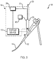
FIGURE 3 illustrates an exemplary bronchoscope system with a real-time system; -
FIGURE 4 is a perspective view of a distal end of a real-time system component formed in accordance with an embodiment; -
FIGURE 5 shows an ultrasound image produced by a radial ultrasound device used within the component ofFIGURE 4 ; -
FIGURE 6 is a perspective view of a distal end of a real-time system component formed in accordance with an embodiment; -
FIGURE 7 is a perspective view of a distal end of a real-time system component formed in accordance with an embodiment; -
FIGURE 8 is a perspective view of a distal end of a real-time system component formed in accordance with an embodiment; -
FIGURE 9 is a cross-sectional view of the component ofFIGURE 8 ; -
FIGURE 10 is a perspective view of a distal end of a real-time system component formed in accordance with an embodiment; and -
FIGURE 11 is a cross-sectional view of the component ofFIGURE 10 . - The following description is merely illustrative in nature and is not intended to limit the present disclosure, application, or uses. The following description explains, by way of illustration only and not of limitation, various embodiments of devices and methods for providing a real-time system.
- Referring now to
FIGURE 3 , abronchoscope system 10 includes abronchoscope 12 with aninsertion tube 14, and a real-time system 16. A diagnostic bronchoscope (e.g., BF-P190 produced by Olympus®) is an example of thebronchoscope 12. The real-time system 16 includes asignal processor 24, adisplay device 18, awire 22 connected to a radial ultrasound transducer (not shown) via ahandle device 20. The real-time system 16 also includes amotor controller 40 connected to a distal motor (not shown) via thehandle device 20. - The real-
time system 16 includes amedical device 30, such as a needle for tissue sampling and/or medicant delivery that is slidably received within a lumen of a catheter (not shown). The catheter is attached at a proximal end to thehandle device 20. The catheter is passed through the handle of thebronchoscope 12 and theinsertion tube 14. The real-time system 16 may be used separate from thebronchoscope system 12. - The
display device 18 is in wired or wireless signal communication with thesignal processor 24. Thedisplay device 18 presents images based on image information received from thesignal processor 24 that receives image information from a radial ultrasound transducer (not shown) of a radial ultrasound probe. -
FIGURE 4 shows anexemplary end component 31 that is attached to a distal end 32 aflexible catheter 33. Theflexible catheter 33 is attached to thehandle device 20 at a proximal end and includes a lumen that is capable of receiving a radial ultrasound device and a smaller working channel for receiving themedical device 30 that is passed through thehandle device 20. In one embodiment, the smaller working channel has an inner diameter that is less than half the inner diameter of the lumen that receives the radial ultrasound device. Theend component 31 includes afirst lumen 34 that is coaxial with the main lumen of theflexible catheter 33 when attached thereto. Thefirst lumen 34 may be capped at the distal end in order to keep any ultrasound conducting fluid or gel within thelumen 34. Theend component 31 includes anexit ramp 36 that allows themedical device 30 received within the working channel of theflexible catheter 33 to exit at a side of theend component 31 near a proximal end. Theend component 31 may be attached to theflexible catheter 33 using epoxy, a thermal weld or a metal-to-metal weld. Theramp 36 could be made of steel while the ultrasound (i.e., US) window (i.e., portion of the end component 31) that surrounds where the probe is received is made of a plastic where theramp 36 is welded to the braided material (not shown) of the sheath on the proximal end and theramp 36 is epoxied to the US window on its distal end. - The
end component 31 includes two longitudinal slots (i.e., grooves) 38, 39 that extend from a distal end to a longitudinal point near theexit ramp 36. Theslots slots slots slots exit ramp 36 toward a target, as shown inultrasound image 42 ofFIGURE 5 . A centerline of theexit ramp 36 bisects theslots - Because the
slots end component 31, the ultrasound reflections are more refined (i.e., minimal shadowing). Various angles between theslots slots slots - The shape of the material within the
slots - As shown in
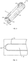
FIGURE 6 , anend cap component 50 includes a proximal section that includes anexit ramp 56 that is positioned relative to the working channel of theflexible catheter 33. Theend cap component 50 includes a distal section that includes atrough 60 that is coaxial with alumen 54 of the proximal section all of which are coaxial with the lumen of theflexible catheter 33 that receives the ultrasound probe. The cross section of the distal section forms roughly a D-shape. This provides direct contact of the ultrasound probe with surrounding tissue. Adjacent to thetrough 60 are slots (i.e., grooves) 68, 70 configured to receive ultrasound reflecting materials like theslots FIGURE 4 . - As shown in
FIGURE 7 , anend cap component 80 includes a proximal section that includes anexit ramp 86 that is positioned relative to the working channel of an attachedflexible catheter 33 when attached thereto. Theend cap component 80 includes a distal section that includes atrough 90 that is coaxial with alumen 84 of the proximal section all of which are coaxial with the lumen of theflexible catheter 33 that receives the ultrasound probe. Less of thetrough 90 is surrounded by material of theend cap component 80 than thetrough 60 of theend cap component 50. Smaller slots (i.e., grooves) 92, 94 are located longitudinally in the outer rounded portion of the distal section and are configured to receive ultrasound reflecting materials like theslots FIGURE 4 . - In one embodiment, as shown in
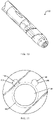
FIGURES 8 and 9 , anend cap component 110 includes aside port 118,orientation pin lumens ultrasound lumen 116 similar to that shown inFIGURE 1 . Theorientation pin lumens FIGURE 3 above, or may just include pockets of gas/air. Thelumens end cap component 110 includes a narrowedport 124 at the distal end for providing access to theultrasound lumen 116. Theport 124 allows for the injection of an ultrasound coupling fluid, such as a viscous gel (e.g., Aquasonic® 100). After injection of the ultrasound coupling fluid, anultrasound probe 126 is inserted into theultrasound lumen 116. Because theultrasound probe 126 has a larger diameter than theport 124, the ultrasound coupling gel remains trapped within theultrasound lumen 116. - As shown in
FIGURES 10 and 11 ,headlight lumens 140 are cut into aprobe lumen 142 of anend cap 130, such that the material (i.e., headlights 144) placed in theheadlight lumens 140 are exposed to theprobe lumen 142. This allows the ultrasound coupling gel that is inserted into theprobe lumen 142 to be in direct contact with the headlights144, forming an ideal coupling for an US signal to reflect from theheadlights 144 back to theUS probe 148. - In one embodiment, the orientation pin lumens and slots that reflect ultrasound signals may have one or more longitudinal breaks (i.e., locations where no lumen or slot exists or no reflective material is used). Because of the breaks one can see in the ultrasound image where the transducer is located at the end cap. This happens because the ultrasound plane has a thickness in the longitudinal direction that is smaller than the length of the US window of the end cap.
- The description of the invention is merely exemplary in nature and variations that do not depart from the gist of the invention are intended to be within the scope of the invention. Such variations are not to be regarded as a departure from the spirit and scope of the invention.
-
- A. An apparatus comprising: a flexible shaft comprising: a first lumen; and a second lumen; and an end cap attached to a distal end of the flexible shaft, the end cap comprising: a first lumen; an exit port located at a proximal end of the end cap; a first slot; and a second slot, wherein the first lumen of the end cap is configured to receive an imaging tool from the first lumen of the flexible shaft when the end cap is attached to the flexible shaft, wherein the exit port is configured to receive a medical device from the second lumen of the flexible shaft when the end cap is attached to the flexible shaft, wherein the slots are located longitudinally on an outer surface of a distal section of the end cap.
- B. The apparatus of A, further comprising an ultrasound reflecting material located in the slots.
- C. The apparatus of A or B, wherein the imaging tool comprises a radial ultrasound probe.
- D. The apparatus of any of A-C, further comprising a trough located at a distal end of the end cap, the trough being configured to receive the imaging tool from the first lumen of the end cap, wherein the first lumen of the end cap is located at a proximal end of the end cap.
- E. The apparatus of D, wherein the slots are located on an outer surface of a portion of the end cap that includes the trough.
- F. The apparatus of D or E, wherein the slots are located on a longitudinal half of the end cap that is opposite the other longitudinal half of the end cap that includes the exit port.
- G. The apparatus of any of D-F, wherein the slots are located on a surface of the end cap adjacent to the trough.
- H. The apparatus of G, wherein the surfaces of the end cap that are adjacent to the trough are located on the longitudinal half of the end cap that includes the slots.
- I. The apparatus of any of A-C, further comprising a second port located at a distal end of the end cap, the second port provides access to the first lumen of the end cap.
- J. The apparatus of I, wherein the second port of the end cap has a smaller cross-sectional diameter than the first lumen of the end cap.
- K. A system comprising: an imaging system comprising: a radial ultrasound probe; an image processor in signal communication with the radial ultrasound probe; and a display configured to display ultrasound images based on signals received from the image processor; and an apparatus comprising: a handle configured to receive a medical device and the radial ultrasound probe; a flexible shaft attached at a proximal end to the handle comprising: a first lumen configured to receive the radial ultrasound probe from the handle; and a second lumen configured to receive the medical device from the handle; and an end cap attached to a distal end of the flexible shaft, the end cap comprising: a first lumen; an exit port located at a proximal end of the end cap; a first slot; and a second slot, wherein the first lumen of the end cap is configured to receive the radial ultrasound probe from the first lumen of the flexible shaft when the end cap is attached to the flexible shaft, wherein the exit port is configured to receive the medical device from the second lumen of the flexible shaft when the end cap is attached to the flexible shaft, wherein the slots are located longitudinally on an outer surface of the end cap at a distal section of the end cap.
- L. The system of K, further comprising at least one ultrasound reflecting material located in each of the slots.
- M. The system of K or L, wherein the apparatus further comprises a trough located at a distal end of the end cap, the trough being configured to receive the radial ultrasound probe from the first lumen of the end cap, wherein the first lumen of the end cap is located at a proximal end of the end cap.
- N. The system of M, wherein the slots are located on at least one of a surface of the end cap adjacent to the trough or an outer surface of a portion of the end cap that includes the trough.
- O. The system of M or N, wherein the slots are located on a longitudinal half of the end cap that is opposite the other longitudinal half of the end cap that includes the exit port.
- P. The system of any of M-O, wherein the surfaces of the end cap that are adjacent to the trough are located on the longitudinal half of the end cap that includes the slots.
- Q. The system of K or L, wherein the apparatus further comprises a second port located at a distal end of the end cap, the second port provides access to the first lumen of the end cap.
- R. The system of Q, wherein the second port of the end cap has a smaller cross-sectional diameter than the first lumen of the end cap.
- Although the preferable embodiments of the present invention have been described hitherto, the present invention is not limited to these embodiments. Additions, omissions, substitutions, and other modifications can be made without departing from the spirit or scope of the present invention.
Claims (14)
- An apparatus comprising:a flexible shaft comprising:a first lumen configured to receive an imaging tool; anda second lumen;an end cap attached to a distal end of the flexible shaft, the end cap comprising:a first lumen configured to receive the imaging tool;an exit port located at a proximal end of the end cap, the exit port configured to receive a medical device from the second lumen of the flexible shaft when the end cap is attached to the flexible shaft;a first slot; anda second slot;a first ultrasound reflecting material disposed in the first slot; anda second ultrasound reflecting material disposed in the second slot.
- The apparatus of Claim 1, wherein at least one of the first ultrasound reflecting material or the second ultrasound reflecting material includes a concave side.
- The apparatus of Claim 2, wherein the concave side is facing the first lumen of the end cap.
- The apparatus of Claim 1, wherein at least one of the first ultrasound reflecting material or the second ultrasound reflecting material includes a flat side.
- The apparatus of Claim 4, wherein the flat side is facing the first lumen of the end cap.
- The apparatus of Claim 1, wherein the imaging tool comprises a radial ultrasound probe.
- The apparatus of Claim 1, wherein the first slot and the second slot are disposed on the same half of the end cap.
- The apparatus of Claim 7, wherein the exit port includes a longitudinal axis disposed between the first slot and the second slot.
- A system comprising:an imaging system comprising:a radial ultrasound probe;an image processor in signal communication with the radial ultrasound probe; anda display configured to display ultrasound images based on signals received from the image processor; andan apparatus comprising:a handle configured to receive a medical device and the radial ultrasound probe;a flexible shaft attached at a proximal end to the handle comprising:a first lumen configured to receive the radial ultrasound probe from the handle; anda second lumen configured to receive the medical device from the handle; and an end cap attached to a distal end of the flexible shaft, the end cap comprising:a first lumen;an exit port located at a proximal end of the end cap;a first slot; anda second slot,wherein the first lumen of the end cap is configured to receive the radial ultrasound probe from the first lumen of the flexible shaft when the end cap is attached to the flexible shaft,wherein the exit port is configured to receive the medical device from the second lumen of the flexible shaft when the end cap is attached to the flexible shaft,wherein the slots are located longitudinally on an outer surface of the end cap at a distal section of the end cap.
- The system of Claim 9, further comprising at least one ultrasound reflecting material located in each of the slots.
- The system of Claim 9, wherein the apparatus further comprises a trough located at a distal end of the end cap, the trough being configured to receive the radial ultrasound probe from the first lumen of the end cap, wherein the first lumen of the end cap is located at a proximal end of the end cap.
- The system of Claim 11, wherein the slots are located on at least one of a surface of the end cap adjacent to the trough or an outer surface of a portion of the end cap that includes the trough.
- The system of Claim 12, wherein the slots are located on a longitudinal half of the end cap that is opposite the other longitudinal half of the end cap that includes the exit port.
- The system of Claim 13, wherein the surfaces of the end cap that are adjacent to the trough are located on the longitudinal half of the end cap that includes the slots.
Applications Claiming Priority (1)
| Application Number | Priority Date | Filing Date | Title |
|---|---|---|---|
| US202063109558P | 2020-11-04 | 2020-11-04 |
Publications (2)
| Publication Number | Publication Date |
|---|---|
| EP3995084A1 true EP3995084A1 (en) | 2022-05-11 |
| EP3995084B1 EP3995084B1 (en) | 2024-10-16 |
Family
ID=78413792
Family Applications (1)
| Application Number | Title | Priority Date | Filing Date |
|---|---|---|---|
| EP21204983.7A Active EP3995084B1 (en) | 2020-11-04 | 2021-10-27 | Tip assemblies for real-time sampling system |
Country Status (4)
| Country | Link |
|---|---|
| US (1) | US12376734B2 (en) |
| EP (1) | EP3995084B1 (en) |
| JP (1) | JP7410916B2 (en) |
| CN (1) | CN114431894B (en) |
Cited By (1)
| Publication number | Priority date | Publication date | Assignee | Title |
|---|---|---|---|---|
| US12376734B2 (en) | 2020-11-04 | 2025-08-05 | Gyrus Acmi, Inc. | Tip assemblies for real-time sampling system |
Citations (3)
| Publication number | Priority date | Publication date | Assignee | Title |
|---|---|---|---|---|
| US20140296708A1 (en) * | 1998-03-25 | 2014-10-02 | Medtronic Vascular, Inc. | Systems and Methods for Delivering Drugs to Selected Locations Within the Body |
| US20190261946A1 (en) * | 2018-02-28 | 2019-08-29 | Spriation Inc.d.b.a. Olympus Respiratory America | Orientation pins for device using radial ultrasound |
| US20200077975A1 (en) * | 2018-09-11 | 2020-03-12 | Spiration Inc. D/b/a Olympus Respiratory America | Radial ultrasound capsule and system |
Family Cites Families (12)
| Publication number | Priority date | Publication date | Assignee | Title |
|---|---|---|---|---|
| JPH0568517A (en) | 1991-08-02 | 1993-03-23 | Nichimo Co Ltd | Method of drying seaweed and seaweed cage used for drying seaweed |
| JPH0737108A (en) | 1993-07-20 | 1995-02-07 | Matsushita Electric Ind Co Ltd | Data communication method |
| JPH0737108U (en) * | 1993-12-22 | 1995-07-11 | アロカ株式会社 | Catheterized ultrasound probe |
| JP3367339B2 (en) | 1996-07-01 | 2003-01-14 | ペンタックス株式会社 | Medical probe guidance device |
| JPH10118070A (en) | 1996-10-16 | 1998-05-12 | Olympus Optical Co Ltd | Ultrasonograph |
| JP3525700B2 (en) * | 1997-09-24 | 2004-05-10 | 富士写真光機株式会社 | Ultrasonic probe |
| JP2001224595A (en) * | 1999-12-08 | 2001-08-21 | Olympus Optical Co Ltd | Ultrasonic probe for microscopic operation |
| US6942661B2 (en) * | 2000-08-30 | 2005-09-13 | Boston Scientific Scimed, Inc. | Fluid cooled apparatus for supporting diagnostic and therapeutic elements in contact with tissue |
| US7267650B2 (en) * | 2002-12-16 | 2007-09-11 | Cardiac Pacemakers, Inc. | Ultrasound directed guiding catheter system and method |
| US11857365B2 (en) | 2019-03-21 | 2024-01-02 | Olympus Medical Systems Corporation | Dual lumen catheter |
| JP7169929B2 (en) * | 2019-04-09 | 2022-11-11 | 富士フイルム株式会社 | ultrasound endoscope |
| US12376734B2 (en) | 2020-11-04 | 2025-08-05 | Gyrus Acmi, Inc. | Tip assemblies for real-time sampling system |
-
2021
- 2021-10-04 US US17/493,320 patent/US12376734B2/en active Active
- 2021-10-27 EP EP21204983.7A patent/EP3995084B1/en active Active
- 2021-11-02 JP JP2021179422A patent/JP7410916B2/en active Active
- 2021-11-03 CN CN202111294483.7A patent/CN114431894B/en active Active
Patent Citations (3)
| Publication number | Priority date | Publication date | Assignee | Title |
|---|---|---|---|---|
| US20140296708A1 (en) * | 1998-03-25 | 2014-10-02 | Medtronic Vascular, Inc. | Systems and Methods for Delivering Drugs to Selected Locations Within the Body |
| US20190261946A1 (en) * | 2018-02-28 | 2019-08-29 | Spriation Inc.d.b.a. Olympus Respiratory America | Orientation pins for device using radial ultrasound |
| US20200077975A1 (en) * | 2018-09-11 | 2020-03-12 | Spiration Inc. D/b/a Olympus Respiratory America | Radial ultrasound capsule and system |
Cited By (1)
| Publication number | Priority date | Publication date | Assignee | Title |
|---|---|---|---|---|
| US12376734B2 (en) | 2020-11-04 | 2025-08-05 | Gyrus Acmi, Inc. | Tip assemblies for real-time sampling system |
Also Published As
| Publication number | Publication date |
|---|---|
| JP7410916B2 (en) | 2024-01-10 |
| CN114431894A (en) | 2022-05-06 |
| CN114431894B (en) | 2026-04-10 |
| US12376734B2 (en) | 2025-08-05 |
| JP2022075595A (en) | 2022-05-18 |
| EP3995084B1 (en) | 2024-10-16 |
| US20220133264A1 (en) | 2022-05-05 |
Similar Documents
| Publication | Publication Date | Title |
|---|---|---|
| JP4982637B2 (en) | Flexible surgical needle device | |
| US4489727A (en) | Device for diagnosing body cavity interior with supersonic waves | |
| US20250255582A1 (en) | Real-time sampling device | |
| US8657749B2 (en) | Ultrasonic puncture needle | |
| US12426853B2 (en) | Orientation pins for device using radial ultrasound | |
| JP6779661B2 (en) | Diagnostic imaging catheter | |
| CN106028954A (en) | Puncture needle for endoscopes | |
| JP6594151B2 (en) | Ultrasound endoscope | |
| EP4289463A1 (en) | Catheter | |
| JP2019162416A (en) | Variable pitch flexible needle | |
| US20220071609A1 (en) | Endoscope puncture needle | |
| US12376734B2 (en) | Tip assemblies for real-time sampling system | |
| US6017311A (en) | Ultrasound probe having an insulating sleeve member | |
| US11883232B2 (en) | Radial ultrasound capsule and system | |
| EP2082695A1 (en) | Injection needle for endoscope, and inner tube having needle body fixed to its distal end | |
| CN117357033A (en) | Instrument channel assembly, insertion portion, and endoscope | |
| JP2616943B2 (en) | Endoscope | |
| CN121891051A (en) | Ultrasonic imaging catheter and imaging system | |
| JP2021020084A (en) | Image diagnosis catheter | |
| JP2015058299A (en) | Treatment member for treating living body, treatment instrument and manufacturing method of treatment member for treating living body |
Legal Events
| Date | Code | Title | Description |
|---|---|---|---|
| PUAI | Public reference made under article 153(3) epc to a published international application that has entered the european phase |
Free format text: ORIGINAL CODE: 0009012 |
|
| STAA | Information on the status of an ep patent application or granted ep patent |
Free format text: STATUS: THE APPLICATION HAS BEEN PUBLISHED |
|
| AK | Designated contracting states |
Kind code of ref document: A1 Designated state(s): AL AT BE BG CH CY CZ DE DK EE ES FI FR GB GR HR HU IE IS IT LI LT LU LV MC MK MT NL NO PL PT RO RS SE SI SK SM TR |
|
| STAA | Information on the status of an ep patent application or granted ep patent |
Free format text: STATUS: REQUEST FOR EXAMINATION WAS MADE |
|
| 17P | Request for examination filed |
Effective date: 20221111 |
|
| RBV | Designated contracting states (corrected) |
Designated state(s): AL AT BE BG CH CY CZ DE DK EE ES FI FR GB GR HR HU IE IS IT LI LT LU LV MC MK MT NL NO PL PT RO RS SE SI SK SM TR |
|
| APBK | Appeal reference recorded |
Free format text: ORIGINAL CODE: EPIDOSNREFNE |
|
| APAF | Appeal reference modified |
Free format text: ORIGINAL CODE: EPIDOSCREFNE |
|
| RAP1 | Party data changed (applicant data changed or rights of an application transferred) |
Owner name: OLYMPUS MEDICAL SYSTEMS CORPORATION |
|
| REG | Reference to a national code |
Ref country code: DE Ref legal event code: R079 Free format text: PREVIOUS MAIN CLASS: A61B0008120000 Ipc: A61B0017340000 Ref country code: DE Ref legal event code: R079 Ref document number: 602021020280 Country of ref document: DE Free format text: PREVIOUS MAIN CLASS: A61B0008120000 Ipc: A61B0017340000 |
|
| GRAP | Despatch of communication of intention to grant a patent |
Free format text: ORIGINAL CODE: EPIDOSNIGR1 |
|
| STAA | Information on the status of an ep patent application or granted ep patent |
Free format text: STATUS: GRANT OF PATENT IS INTENDED |
|
| RIC1 | Information provided on ipc code assigned before grant |
Ipc: A61B 90/00 20160101ALI20240503BHEP Ipc: A61B 8/12 20060101ALI20240503BHEP Ipc: A61B 8/00 20060101ALI20240503BHEP Ipc: A61B 17/34 20060101AFI20240503BHEP |
|
| INTG | Intention to grant announced |
Effective date: 20240523 |
|
| GRAS | Grant fee paid |
Free format text: ORIGINAL CODE: EPIDOSNIGR3 |
|
| GRAA | (expected) grant |
Free format text: ORIGINAL CODE: 0009210 |
|
| STAA | Information on the status of an ep patent application or granted ep patent |
Free format text: STATUS: THE PATENT HAS BEEN GRANTED |
|
| AK | Designated contracting states |
Kind code of ref document: B1 Designated state(s): AL AT BE BG CH CY CZ DE DK EE ES FI FR GB GR HR HU IE IS IT LI LT LU LV MC MK MT NL NO PL PT RO RS SE SI SK SM TR |
|
| REG | Reference to a national code |
Ref country code: GB Ref legal event code: FG4D |
|
| REG | Reference to a national code |
Ref country code: CH Ref legal event code: EP |
|
| REG | Reference to a national code |
Ref country code: IE Ref legal event code: FG4D |
|
| REG | Reference to a national code |
Ref country code: DE Ref legal event code: R096 Ref document number: 602021020280 Country of ref document: DE |
|
| REG | Reference to a national code |
Ref country code: LT Ref legal event code: MG9D |
|
| REG | Reference to a national code |
Ref country code: NL Ref legal event code: MP Effective date: 20241016 |
|
| REG | Reference to a national code |
Ref country code: AT Ref legal event code: MK05 Ref document number: 1732287 Country of ref document: AT Kind code of ref document: T Effective date: 20241016 |
|
| PG25 | Lapsed in a contracting state [announced via postgrant information from national office to epo] |
Ref country code: NL Free format text: LAPSE BECAUSE OF FAILURE TO SUBMIT A TRANSLATION OF THE DESCRIPTION OR TO PAY THE FEE WITHIN THE PRESCRIBED TIME-LIMIT Effective date: 20241016 |
|
| PG25 | Lapsed in a contracting state [announced via postgrant information from national office to epo] |
Ref country code: NL Free format text: LAPSE BECAUSE OF FAILURE TO SUBMIT A TRANSLATION OF THE DESCRIPTION OR TO PAY THE FEE WITHIN THE PRESCRIBED TIME-LIMIT Effective date: 20241016 |
|
| PG25 | Lapsed in a contracting state [announced via postgrant information from national office to epo] |
Ref country code: IS Free format text: LAPSE BECAUSE OF FAILURE TO SUBMIT A TRANSLATION OF THE DESCRIPTION OR TO PAY THE FEE WITHIN THE PRESCRIBED TIME-LIMIT Effective date: 20250216 Ref country code: PT Free format text: LAPSE BECAUSE OF FAILURE TO SUBMIT A TRANSLATION OF THE DESCRIPTION OR TO PAY THE FEE WITHIN THE PRESCRIBED TIME-LIMIT Effective date: 20250217 Ref country code: HR Free format text: LAPSE BECAUSE OF FAILURE TO SUBMIT A TRANSLATION OF THE DESCRIPTION OR TO PAY THE FEE WITHIN THE PRESCRIBED TIME-LIMIT Effective date: 20241016 |
|
| PG25 | Lapsed in a contracting state [announced via postgrant information from national office to epo] |
Ref country code: FI Free format text: LAPSE BECAUSE OF FAILURE TO SUBMIT A TRANSLATION OF THE DESCRIPTION OR TO PAY THE FEE WITHIN THE PRESCRIBED TIME-LIMIT Effective date: 20241016 |
|
| PG25 | Lapsed in a contracting state [announced via postgrant information from national office to epo] |
Ref country code: BG Free format text: LAPSE BECAUSE OF FAILURE TO SUBMIT A TRANSLATION OF THE DESCRIPTION OR TO PAY THE FEE WITHIN THE PRESCRIBED TIME-LIMIT Effective date: 20241016 |
|
| PG25 | Lapsed in a contracting state [announced via postgrant information from national office to epo] |
Ref country code: ES Free format text: LAPSE BECAUSE OF FAILURE TO SUBMIT A TRANSLATION OF THE DESCRIPTION OR TO PAY THE FEE WITHIN THE PRESCRIBED TIME-LIMIT Effective date: 20241016 |
|
| PG25 | Lapsed in a contracting state [announced via postgrant information from national office to epo] |
Ref country code: NO Free format text: LAPSE BECAUSE OF FAILURE TO SUBMIT A TRANSLATION OF THE DESCRIPTION OR TO PAY THE FEE WITHIN THE PRESCRIBED TIME-LIMIT Effective date: 20250116 |
|
| PG25 | Lapsed in a contracting state [announced via postgrant information from national office to epo] |
Ref country code: GR Free format text: LAPSE BECAUSE OF FAILURE TO SUBMIT A TRANSLATION OF THE DESCRIPTION OR TO PAY THE FEE WITHIN THE PRESCRIBED TIME-LIMIT Effective date: 20250117 Ref country code: LV Free format text: LAPSE BECAUSE OF FAILURE TO SUBMIT A TRANSLATION OF THE DESCRIPTION OR TO PAY THE FEE WITHIN THE PRESCRIBED TIME-LIMIT Effective date: 20241016 Ref country code: AT Free format text: LAPSE BECAUSE OF FAILURE TO SUBMIT A TRANSLATION OF THE DESCRIPTION OR TO PAY THE FEE WITHIN THE PRESCRIBED TIME-LIMIT Effective date: 20241016 |
|
| PG25 | Lapsed in a contracting state [announced via postgrant information from national office to epo] |
Ref country code: PL Free format text: LAPSE BECAUSE OF FAILURE TO SUBMIT A TRANSLATION OF THE DESCRIPTION OR TO PAY THE FEE WITHIN THE PRESCRIBED TIME-LIMIT Effective date: 20241016 |
|
| PG25 | Lapsed in a contracting state [announced via postgrant information from national office to epo] |
Ref country code: RS Free format text: LAPSE BECAUSE OF FAILURE TO SUBMIT A TRANSLATION OF THE DESCRIPTION OR TO PAY THE FEE WITHIN THE PRESCRIBED TIME-LIMIT Effective date: 20250116 |
|
| REG | Reference to a national code |
Ref country code: CH Ref legal event code: PL |
|
| PG25 | Lapsed in a contracting state [announced via postgrant information from national office to epo] |
Ref country code: SM Free format text: LAPSE BECAUSE OF FAILURE TO SUBMIT A TRANSLATION OF THE DESCRIPTION OR TO PAY THE FEE WITHIN THE PRESCRIBED TIME-LIMIT Effective date: 20241016 |
|
| PG25 | Lapsed in a contracting state [announced via postgrant information from national office to epo] |
Ref country code: MC Free format text: LAPSE BECAUSE OF FAILURE TO SUBMIT A TRANSLATION OF THE DESCRIPTION OR TO PAY THE FEE WITHIN THE PRESCRIBED TIME-LIMIT Effective date: 20241016 |
|
| PG25 | Lapsed in a contracting state [announced via postgrant information from national office to epo] |
Ref country code: DK Free format text: LAPSE BECAUSE OF FAILURE TO SUBMIT A TRANSLATION OF THE DESCRIPTION OR TO PAY THE FEE WITHIN THE PRESCRIBED TIME-LIMIT Effective date: 20241016 |
|
| PG25 | Lapsed in a contracting state [announced via postgrant information from national office to epo] |
Ref country code: LU Free format text: LAPSE BECAUSE OF NON-PAYMENT OF DUE FEES Effective date: 20241027 Ref country code: BE Free format text: LAPSE BECAUSE OF NON-PAYMENT OF DUE FEES Effective date: 20241031 |
|
| REG | Reference to a national code |
Ref country code: DE Ref legal event code: R097 Ref document number: 602021020280 Country of ref document: DE |
|
| PG25 | Lapsed in a contracting state [announced via postgrant information from national office to epo] |
Ref country code: EE Free format text: LAPSE BECAUSE OF FAILURE TO SUBMIT A TRANSLATION OF THE DESCRIPTION OR TO PAY THE FEE WITHIN THE PRESCRIBED TIME-LIMIT Effective date: 20241016 |
|
| PG25 | Lapsed in a contracting state [announced via postgrant information from national office to epo] |
Ref country code: CH Free format text: LAPSE BECAUSE OF NON-PAYMENT OF DUE FEES Effective date: 20241031 |
|
| PG25 | Lapsed in a contracting state [announced via postgrant information from national office to epo] |
Ref country code: RO Free format text: LAPSE BECAUSE OF FAILURE TO SUBMIT A TRANSLATION OF THE DESCRIPTION OR TO PAY THE FEE WITHIN THE PRESCRIBED TIME-LIMIT Effective date: 20241016 |
|
| PG25 | Lapsed in a contracting state [announced via postgrant information from national office to epo] |
Ref country code: SK Free format text: LAPSE BECAUSE OF FAILURE TO SUBMIT A TRANSLATION OF THE DESCRIPTION OR TO PAY THE FEE WITHIN THE PRESCRIBED TIME-LIMIT Effective date: 20241016 |
|
| PG25 | Lapsed in a contracting state [announced via postgrant information from national office to epo] |
Ref country code: CZ Free format text: LAPSE BECAUSE OF FAILURE TO SUBMIT A TRANSLATION OF THE DESCRIPTION OR TO PAY THE FEE WITHIN THE PRESCRIBED TIME-LIMIT Effective date: 20241016 |
|
| PG25 | Lapsed in a contracting state [announced via postgrant information from national office to epo] |
Ref country code: IT Free format text: LAPSE BECAUSE OF FAILURE TO SUBMIT A TRANSLATION OF THE DESCRIPTION OR TO PAY THE FEE WITHIN THE PRESCRIBED TIME-LIMIT Effective date: 20241016 |
|
| REG | Reference to a national code |
Ref country code: BE Ref legal event code: MM Effective date: 20241031 |
|
| PLBE | No opposition filed within time limit |
Free format text: ORIGINAL CODE: 0009261 |
|
| STAA | Information on the status of an ep patent application or granted ep patent |
Free format text: STATUS: NO OPPOSITION FILED WITHIN TIME LIMIT |
|
| PG25 | Lapsed in a contracting state [announced via postgrant information from national office to epo] |
Ref country code: SE Free format text: LAPSE BECAUSE OF FAILURE TO SUBMIT A TRANSLATION OF THE DESCRIPTION OR TO PAY THE FEE WITHIN THE PRESCRIBED TIME-LIMIT Effective date: 20241016 |
|
| 26N | No opposition filed |
Effective date: 20250717 |
|
| PG25 | Lapsed in a contracting state [announced via postgrant information from national office to epo] |
Ref country code: IE Free format text: LAPSE BECAUSE OF NON-PAYMENT OF DUE FEES Effective date: 20241027 |
|
| PGFP | Annual fee paid to national office [announced via postgrant information from national office to epo] |
Ref country code: DE Payment date: 20251029 Year of fee payment: 5 |
|
| PGFP | Annual fee paid to national office [announced via postgrant information from national office to epo] |
Ref country code: FR Payment date: 20251027 Year of fee payment: 5 |
|
| PG25 | Lapsed in a contracting state [announced via postgrant information from national office to epo] |
Ref country code: CY Free format text: LAPSE BECAUSE OF FAILURE TO SUBMIT A TRANSLATION OF THE DESCRIPTION OR TO PAY THE FEE WITHIN THE PRESCRIBED TIME-LIMIT; INVALID AB INITIO Effective date: 20211027 |
|
| PG25 | Lapsed in a contracting state [announced via postgrant information from national office to epo] |
Ref country code: HU Free format text: LAPSE BECAUSE OF FAILURE TO SUBMIT A TRANSLATION OF THE DESCRIPTION OR TO PAY THE FEE WITHIN THE PRESCRIBED TIME-LIMIT; INVALID AB INITIO Effective date: 20211027 |