EP3994969B1 - Earth auger - Google Patents
Earth auger Download PDFInfo
- Publication number
- EP3994969B1 EP3994969B1 EP21202842.7A EP21202842A EP3994969B1 EP 3994969 B1 EP3994969 B1 EP 3994969B1 EP 21202842 A EP21202842 A EP 21202842A EP 3994969 B1 EP3994969 B1 EP 3994969B1
- Authority
- EP
- European Patent Office
- Prior art keywords
- assembly
- earth auger
- lever
- trigger
- projection
- Prior art date
- Legal status (The legal status is an assumption and is not a legal conclusion. Google has not performed a legal analysis and makes no representation as to the accuracy of the status listed.)
- Active
Links
Images


Classifications
-
- A—HUMAN NECESSITIES
- A01—AGRICULTURE; FORESTRY; ANIMAL HUSBANDRY; HUNTING; TRAPPING; FISHING
- A01C—PLANTING; SOWING; FERTILISING
- A01C5/00—Making or covering furrows or holes for sowing, planting or manuring
- A01C5/02—Hand tools for making holes for sowing, planting or manuring
-
- A—HUMAN NECESSITIES
- A01—AGRICULTURE; FORESTRY; ANIMAL HUSBANDRY; HUNTING; TRAPPING; FISHING
- A01C—PLANTING; SOWING; FERTILISING
- A01C11/00—Transplanting machines
- A01C11/04—Transplanting machines for deeper setting or shifting of plants
-
- E—FIXED CONSTRUCTIONS
- E21—EARTH OR ROCK DRILLING; MINING
- E21B—EARTH OR ROCK DRILLING; OBTAINING OIL, GAS, WATER, SOLUBLE OR MELTABLE MATERIALS OR A SLURRY OF MINERALS FROM WELLS
- E21B10/00—Drill bits
- E21B10/44—Bits with helical conveying portion, e.g. screw type bits; Augers with leading portion or with detachable parts
-
- E—FIXED CONSTRUCTIONS
- E21—EARTH OR ROCK DRILLING; MINING
- E21B—EARTH OR ROCK DRILLING; OBTAINING OIL, GAS, WATER, SOLUBLE OR MELTABLE MATERIALS OR A SLURRY OF MINERALS FROM WELLS
- E21B11/00—Other drilling tools
- E21B11/005—Hand operated drilling tools
-
- E—FIXED CONSTRUCTIONS
- E21—EARTH OR ROCK DRILLING; MINING
- E21B—EARTH OR ROCK DRILLING; OBTAINING OIL, GAS, WATER, SOLUBLE OR MELTABLE MATERIALS OR A SLURRY OF MINERALS FROM WELLS
- E21B3/00—Rotary drilling
- E21B3/02—Surface drives for rotary drilling
-
- E—FIXED CONSTRUCTIONS
- E02—HYDRAULIC ENGINEERING; FOUNDATIONS; SOIL SHIFTING
- E02F—DREDGING; SOIL-SHIFTING
- E02F3/00—Dredgers; Soil-shifting machines
- E02F3/04—Dredgers; Soil-shifting machines mechanically-driven
- E02F3/06—Dredgers; Soil-shifting machines mechanically-driven with digging screws
Definitions
- the disclosure belongs to the technical field of garden machinery and particularly relates to an earth auger capable of braking in time when the rotation is locked.
- Earth augers are widely used in landscaping projects for seedlings on slopes, sandy and hard soils, such as planting digging, digging the outer soil of large trees, burying piles and digging holes in fences, fertilizing, digging holes for fruit trees and cultivation and weeding in landscaping projects and so on.
- the digging diameter of the earth auger is usually between 200mm-600mm, and the number of digging pits per hour is not less than 80.
- 640 pits can be dug, which is more than 30 times that of manual work. It can be seen that the working efficiency of earth auger is much higher than manual operation, which makes people free from heavy physical labor.
- the disclosure provides an earth auger, which can passively trigger the brake assembly when the rotation is blocked, so as to effectively prevent accidental injuries and improve the safety performance of the earth auger.
- the disclosure provides an earth auger comprising: a supporting assembly, a drill pipe assembly including a drill pipe, a driving assembly arranged on the supporting assembly to drive the drill pipe assembly to work, and a brake assembly including a trigger component that brakes the driving assembly and a brake lever connected through a first pivot and matched with the trigger component.
- a projection part of the brake lever on a plane perpendicular to an axis of the drill pipe is located outside a projection of the supporting assembly on the plane perpendicular to the axis of the drill pipe.
- the disclosure also provides an earth auger comprising: a supporting assembly, a drill pipe assembly including a drill pipe, a driving assembly arranged on the supporting assembly to drive the drill pipe assembly to work, and a brake assembly including a trigger component that brakes the driving assembly and a brake lever connected through a first pivot and matched with the trigger component.
- a drill of the earth auger is blocked, the brake lever is in contact with the operator, so that the brake lever triggers the trigger component and then brakes the driving assembly.
- the disclosure provides an earth auger that can passively trigger the brake assembly when the drill is blocked, thereby effectively preventing accidents and improving the safety performance of the earth auger.
- the torque bearing components 112 are evenly distributed on the periphery of the through hole 111, so that each torque bearing component 112 bears almost equal torques and the damage to the torque bearing component 112 due to uneven torque bearing is effectively avoided.
- the lamp trough 113 penetrates the supporting platform 11 in a direction perpendicular to the supporting platform 11.
- the numbers of the lamp trough 113 and the torque bearing component 112 can be three, for example.
- the torque bearing components 112 and the lamp troughs 113 are evenly distributed on the periphery of the through hole 11 and the torque bearing component 112 and the lamp trough 113 are set apart from each other.
- the bracket 12 includes a main bracket 121 and an armrest frame 122, and the armrest frame 122 is formed by bending and extending both sides of the main bracket 121.
- the supporting platform 11 is mounted on the main bracket 121 by screws, and a grip cover 1221 can be provided on the armrest frame 122 to improve the user's feeling.
- the handle assembly 20 can be mounted on the armrest frame 122.
- the grip cover 1221 is mounted on one side of the armrest frame 122, and a handle assembly 20 is mounted on the other side.
- the handle assembly 20 is located on the armrest frame 122 held by the operator's right hand.
- the handle assembly 20 includes a handle shell 21, a starting unit 22, a locking unit 23 and a reversing unit 24.
- the handle shell 21 includes a top wall 211, a bottom wall 212 and a side wall 213.
- the bottom wall 212 is arranged opposite to the top wall 211.
- the top wall 211, the bottom wall 212 and the side wall 213 form a receiving cavity 214 for housing the starting unit 22, the locking unit 23 and the reversing unit 24.
- the starting unit 22 includes a trigger 221, a starting micro switch 222 and a trigger reset elastic component 223.
- the trigger 221 can be pivotally mounted on the handle shell 21 through a second pivot 224, and the starting micro switch 222 is matched with the trigger 221.
- the trigger 221 includes a handle arm 2211 and a trigger arm 2212.
- the handle arm 2211 and the trigger arm 2212 are located on two sides of the second pivot 224 and the handle arm 2211 passes through the side wall 213 of the handle shell 21 for user to operate.
- the handle arm 2211 passes through the side wall 213 facing the driving assembly 40 which is convenient for the user to operate the handle arm 2211 with the thumb when holding the handle assembly 20.
- the trigger arm 2212 is located in the receiving cavity 214 of the handle shell 21 and matches with the starting micro switch 222.
- the trigger arm 2212 rotates around the second pivot 224 and resists the starting micro switch 222, so that the starting micro switch 222 can be triggered.
- the trigger reset elastic component 223 will undergoes elastic deformation and the starting micro switch 222 can control the driving assembly 40.
- the starting micro switch 222 directly sends the starting signal to the driving assembly 40
- the starting micro switch 222 directly controls the driving component 40 to work.
- the locking unit 23 includes a locking handle 231 and a reset elastic component 232, and the reset elastic component 232 matches with the locking handle 231.
- the locking handle 231 can be pivotally mounted on the top wall 211 of the handle shell 21 through a third pivot 233.
- the locking handle 231 includes a pushing arm 2311 and a locking arm 2312.
- the pushing arm 2311 and the locking arm 2312 are located on two sides of the third pivot 233 and the pushing arm 2311 passes through the top wall 211 of the handle shell 21 for user to operate.
- the locking arm 2312 is located in the receiving cavity 214 of the handle shell 21 and matches with the trigger arm 2212.
- the locking arm 2312 when the locking unit 23 is in the locked state, the locking arm 2312 is in contact with the trigger arm 2212. At this time, the user cannot push the handle arm 2211, the starting unit 22 is locked by the locking unit 23 and the driving assembly 40 cannot be started.
- the locking arm 2312 When the user pushes the pushing arm 2311 to rotate around the third pivot 233, the locking arm 2312 also rotates around the third pivot 233 and is separated from the trigger arm 2212. At this time, the locking unit 23 is in the unlocked state and the user can push the handle arm 2211 to start the driving assembly 40.
- the reversing unit 24 includes a sliding rail 241, a sliding block 242 and a reversing micro switch 243.
- the sliding rail 241 is mounted on the side wall 213 of the handle shell 21, the sliding block 242 is slidably mounted on the sliding rail 241, and the reversing micro switch 243 matches with the sliding block 242.
- the reversing micro switch 243 can be located above the sliding direction of the sliding block 242. When the user pushes the sliding block 242 to slide along the sliding rail 241, the sliding block 242 is in contact with the reversing micro switch 243 and triggers the reversing micro switch 243 to work.
- the reversing micro switch 243 sends a reversing signal to the driving assembly 40 to control the driving assembly 40 to rotate forward or reverse.
- the handle assembly 20 guides the operator's hand to be in a grip state through the match of the starting unit 22 and the locking unit 23 and the positions of the match of the starting unit 22 and the locking unit 23 on the handle shell 21, so that the operator can cope with sudden changes in large torques at any time, which cause the thumb triggering the trigger arm 2211 can be easily released, thereby the earth auger is braked and powered off, and the safety risk caused by the failure to release the switch in time can be avoided.
- the spiral angle of the spiral drill vane 312 can be ⁇
- the spiral distance can be P
- the drill diameter of the drill pipe assembly 30 is D
- FIG. 12 is a handle assembly 80 according to yet another embodiment of the disclosure.
- the handle assembly 80 includes a locking unit 83.
- the locking unit 83 includes a locking handle 831 slidably mounted on the handle shell 81 and a reset elastic component 832.
- the earth auger provided by the disclosure can passively trigger the brake assembly when the earth auger is out of control due to the blocked rotation, thereby effectively avoiding accidents and improving operational safety.
- the disclosure has provides following beneficial effects: when the earth auger is out of control due to the blocked rotation, the brake assembly is passively triggered, which effectively avoids accidents and improves operational safety.
Landscapes
- Life Sciences & Earth Sciences (AREA)
- Engineering & Computer Science (AREA)
- Geology (AREA)
- Mining & Mineral Resources (AREA)
- Physics & Mathematics (AREA)
- Environmental & Geological Engineering (AREA)
- Fluid Mechanics (AREA)
- Mechanical Engineering (AREA)
- General Life Sciences & Earth Sciences (AREA)
- Geochemistry & Mineralogy (AREA)
- Soil Sciences (AREA)
- Environmental Sciences (AREA)
- Earth Drilling (AREA)
Description
- The disclosure belongs to the technical field of garden machinery and particularly relates to an earth auger capable of braking in time when the rotation is locked.
- Earth augers are widely used in landscaping projects for seedlings on slopes, sandy and hard soils, such as planting digging, digging the outer soil of large trees, burying piles and digging holes in fences, fertilizing, digging holes for fruit trees and cultivation and weeding in landscaping projects and so on. The digging diameter of the earth auger is usually between 200mm-600mm, and the number of digging pits per hour is not less than 80. According to the normal 8-hour working time of a day, 640 pits can be dug, which is more than 30 times that of manual work. It can be seen that the working efficiency of earth auger is much higher than manual operation, which makes people free from heavy physical labor.
- A prior art earth auger is disclosed in
DE1297046B . The document discloses an earth drilling device having a drive unit connected to at least one support frame. The support frame has two handles which are spaced apart and radially spaced on the same side of the drilling axis at approximately the same height and are connected to one another via a connecting part which merges into the end of one handle. - Another prior art earth auger is disclosed in
CN110899773A . The document discloses an electric drill comprising a support, a drill rod, a motor assembly and a switch assembly provided with the self-locking button so that the electric drill can be started only when the switch and the self-locking button are triggered at the same time. - However, when drilling a hole in the ground, it may happen that the roots of the trees or the stones and other foreign objects are drilled and cause blocked rotation. At this time, there will be a great reaction torque transmitted to the operator through the earth auger. Once the reaction torque exceeds the operator's control range, it will cause the auger to lose control and an injury accident will happen.
- One solution is provided in
US5358062A1 disclosing a portable handheld drilling apparatus for receiving and driving a drill which can encounter a drilling resistance during a drilling operation thereby causing the drilling apparatus to undergo an unwanted rotational movement. - In view of the problems mentioned above, it is necessary to provide a new earth auger to solve these problems.
- In view of the shortcomings of the above solution, the disclosure provides an earth auger, which can passively trigger the brake assembly when the rotation is blocked, so as to effectively prevent accidental injuries and improve the safety performance of the earth auger.
- The disclosure provides an earth auger comprising: a supporting assembly, a drill pipe assembly including a drill pipe, a driving assembly arranged on the supporting assembly to drive the drill pipe assembly to work, and a brake assembly including a trigger component that brakes the driving assembly and a brake lever connected through a first pivot and matched with the trigger component. A projection part of the brake lever on a plane perpendicular to an axis of the drill pipe is located outside a projection of the supporting assembly on the plane perpendicular to the axis of the drill pipe.
- The disclosure also provides an earth auger comprising: a supporting assembly, a drill pipe assembly including a drill pipe, a driving assembly arranged on the supporting assembly to drive the drill pipe assembly to work, and a brake assembly including a trigger component that brakes the driving assembly and a brake lever connected through a first pivot and matched with the trigger component. When a drill of the earth auger is blocked, the brake lever is in contact with the operator, so that the brake lever triggers the trigger component and then brakes the driving assembly.
- In summary, the disclosure provides an earth auger that can passively trigger the brake assembly when the drill is blocked, thereby effectively preventing accidents and improving the safety performance of the earth auger.
-
-
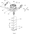
FIG. 1 is a schematic perspective view of an earth auger of the disclosure. -
FIG. 2 is a schematic perspective view of a supporting assembly. -
FIG. 3 is a schematic perspective view of a handle assembly. -
FIG. 4 is a schematic view of an internal structure of the handle assembly shown inFIG. 3 . -
FIG. 5 is a schematic view of the match of the starting unit, the locking unit and the reversing unit. -
FIG. 6 is a partial schematic view of a drill pipe assembly. -
FIG. 7 is a schematic view of a structure of a splitter plate. -
FIG. 8 is a schematic view of a structure of a driving assembly mounted on a supporting platform. -
FIG. 9 is a cross-sectional view ofFIG. 8 . -
FIG. 10 is a bottom view of an earth auger with the drill pipe assembly removed. -
FIG. 11 is a schematic view of an internal structure of a handle assembly in another embodiment. -
FIG. 12 is a schematic view of an internal structure of a handle assembly of a third embodiment. -
FIG. 13 is a schematic view of the match of a trigger and a locking handle of the handle assembly shown inFIG. 12 . - The following describes the implementation of the disclosure through specific embodiments, and those skilled in the art can easily understand other advantages and effects of the disclosure from the content disclosed in this specification.
- It should be noted that the figures provided in this embodiment only illustrate the basic idea of the disclosure in a schematic manner. The figures only show the components related to the disclosure instead of drawing according to the number, shape and size of the components during actual implementation. The type, number and proportion of each component during actual implementation can be changed at will, and the layout of its components may also be more complicated.
- The disclosure provides an earth auger that can passively trigger the brake assembly when the drill is blocked, thereby effectively preventing accidents and ensuring the operators' safety.
- Please refer to
FIG. 1 , the disclosure provides anearth auger 100 which includes a supportingassembly 10, ahandle assembly 20 mounted on the supportingassembly 10, adrill pipe assembly 30, adriving assembly 40, alighting assembly 50 and abrake assembly 60. Thedriving assembly 40 can be mounted on the supportingassembly 10 to drive thedrill pipe assembly 30 to work. - Please refer to
FIG. 1 andFIG. 2 , the supportingassembly 10 includes a supportingplatform 11 and abracket 12. The supportingplatform 11 can be in the shape of a flat plate and mounted on thebracket 12. The supportingplatform 11 can be provided with athrough hole 111, a torque bearingcomponent 112, and alamp trough 113 which are matched with thedriving assembly 40. The torque bearingcomponents 112 is used to bear the torque transmitted by thedriving assembly 40 to the supportingplatform 11, and the number of the torque bearingcomponent 112 can be set according to different structural requirements. When the number oftorque bearing components 112 is more than one, thetorque bearing components 112 are evenly distributed on the periphery of thethrough hole 111, so that each torque bearingcomponent 112 bears almost equal torques and the damage to the torque bearingcomponent 112 due to uneven torque bearing is effectively avoided. Thelamp trough 113 penetrates the supportingplatform 11 in a direction perpendicular to the supportingplatform 11. In this embodiment, the numbers of thelamp trough 113 and the torque bearingcomponent 112 can be three, for example. The torque bearingcomponents 112 and thelamp troughs 113 are evenly distributed on the periphery of the throughhole 11 and the torque bearingcomponent 112 and thelamp trough 113 are set apart from each other. Thebracket 12 includes amain bracket 121 and anarmrest frame 122, and thearmrest frame 122 is formed by bending and extending both sides of themain bracket 121. The supportingplatform 11 is mounted on themain bracket 121 by screws, and agrip cover 1221 can be provided on thearmrest frame 122 to improve the user's feeling. - Please refer to
FIG. 2 to FIG. 5 , thehandle assembly 20 can be mounted on thearmrest frame 122. In this embodiment, thegrip cover 1221 is mounted on one side of thearmrest frame 122, and ahandle assembly 20 is mounted on the other side. When theearth auger 100 is in a normal working state, thehandle assembly 20 is located on thearmrest frame 122 held by the operator's right hand. Thehandle assembly 20 includes ahandle shell 21, astarting unit 22, alocking unit 23 and areversing unit 24. Thehandle shell 21 includes atop wall 211, abottom wall 212 and aside wall 213. Thebottom wall 212 is arranged opposite to thetop wall 211. Thetop wall 211, thebottom wall 212 and theside wall 213 form areceiving cavity 214 for housing thestarting unit 22, thelocking unit 23 and thereversing unit 24. Thestarting unit 22 includes atrigger 221, astarting micro switch 222 and a trigger resetelastic component 223. Thetrigger 221 can be pivotally mounted on thehandle shell 21 through asecond pivot 224, and thestarting micro switch 222 is matched with thetrigger 221. Thetrigger 221 includes ahandle arm 2211 and atrigger arm 2212. Thehandle arm 2211 and thetrigger arm 2212 are located on two sides of thesecond pivot 224 and thehandle arm 2211 passes through theside wall 213 of thehandle shell 21 for user to operate. Thehandle arm 2211 passes through theside wall 213 facing the drivingassembly 40 which is convenient for the user to operate thehandle arm 2211 with the thumb when holding thehandle assembly 20. Thetrigger arm 2212 is located in the receivingcavity 214 of thehandle shell 21 and matches with the startingmicro switch 222. When the user pushes thehandle arm 2211, thetrigger arm 2212 rotates around thesecond pivot 224 and resists the startingmicro switch 222, so that the startingmicro switch 222 can be triggered. At this time, the trigger resetelastic component 223 will undergoes elastic deformation and the startingmicro switch 222 can control the drivingassembly 40. When the startingmicro switch 222 directly sends the starting signal to the drivingassembly 40, the startingmicro switch 222 directly controls the drivingcomponent 40 to work. When the startingmicro switch 222 sends a starting signal to the control unit and the control unit controls the drivingassembly 40 to work, the startmicro switch 222 indirectly controls the drivingassembly 40 to work. When thehandle arm 2211 is released, thetrigger 221 will be reset under the action of the trigger resetelastic component 223. - Please refer to
FIG. 3 andFIG. 4 , the lockingunit 23 includes alocking handle 231 and a resetelastic component 232, and the resetelastic component 232 matches with thelocking handle 231. The locking handle 231 can be pivotally mounted on thetop wall 211 of thehandle shell 21 through athird pivot 233. The locking handle 231 includes a pushingarm 2311 and alocking arm 2312. The pushingarm 2311 and thelocking arm 2312 are located on two sides of thethird pivot 233 and the pushingarm 2311 passes through thetop wall 211 of thehandle shell 21 for user to operate. Thelocking arm 2312 is located in the receivingcavity 214 of thehandle shell 21 and matches with thetrigger arm 2212. - Please refer to
FIG. 5 , when the lockingunit 23 is in the locked state, thelocking arm 2312 is in contact with thetrigger arm 2212. At this time, the user cannot push thehandle arm 2211, thestarting unit 22 is locked by the lockingunit 23 and the drivingassembly 40 cannot be started. When the user pushes the pushingarm 2311 to rotate around thethird pivot 233, thelocking arm 2312 also rotates around thethird pivot 233 and is separated from thetrigger arm 2212. At this time, the lockingunit 23 is in the unlocked state and the user can push thehandle arm 2211 to start the drivingassembly 40. - Please refer to
FIG. 5 andFIG. 3 , the reversingunit 24 includes a slidingrail 241, a slidingblock 242 and a reversingmicro switch 243. The slidingrail 241 is mounted on theside wall 213 of thehandle shell 21, the slidingblock 242 is slidably mounted on the slidingrail 241, and the reversingmicro switch 243 matches with the slidingblock 242. In this embodiment, the reversingmicro switch 243 can be located above the sliding direction of the slidingblock 242. When the user pushes the slidingblock 242 to slide along the slidingrail 241, the slidingblock 242 is in contact with the reversingmicro switch 243 and triggers the reversingmicro switch 243 to work. At this time, the reversingmicro switch 243 sends a reversing signal to the drivingassembly 40 to control the drivingassembly 40 to rotate forward or reverse. Thehandle assembly 20 guides the operator's hand to be in a grip state through the match of thestarting unit 22 and the lockingunit 23 and the positions of the match of thestarting unit 22 and the lockingunit 23 on thehandle shell 21, so that the operator can cope with sudden changes in large torques at any time, which cause the thumb triggering thetrigger arm 2211 can be easily released, thereby the earth auger is braked and powered off, and the safety risk caused by the failure to release the switch in time can be avoided. - Please refer to
FIG. 6, FIG. 7 andFIG. 1 , thedrill pipe assembly 30 can be mounted on the drivingassembly 40 so as to work under the drive of the drivingassembly 40. Thedrill pipe assembly 30 includes adrill pipe 31 and asplitter plate 32. Thesplitter plate 32 is mounted at an end of thedrill pipe 31 away from the drivingassembly 40. Thedrill pipe 31 includes adrill shaft 311 mounted on the drivingassembly 40 and aspiral drill vane 312 mounted on thedrill shaft 311. - Please refer to
FIG. 6 andFIG. 1 , the spiral angle of thespiral drill vane 312 can be α, the spiral distance can be P, and the drill diameter of thedrill pipe assembly 30 is D, then the following relationship can be formed:

- Wherein, the center of the
splitter plate 32 may be provided with a shaft hole matching with thedrill shaft 311, and thesplitter plate 32 is mounted on thedrill shaft 311 through the shaft hole. Thesplitter plate 32 includes abase plate 321 and adrainage unit 322. Thedrainage 322 can be arranged on thebase plate 321. Thebase plate 321 can be in the shape of a circular flat plate, the diameter of thebase plate 321 can be set to be equal or similar to the drill diameter D and thebase plate 321 can be perpendicular to thedrill shaft 311. Thedrainage unit 322 includes adrainage port 3221, adrainage plate 3222 and ablade 3223. Thedrainage port 3221 is arranged on thebase plate 321, thedrainage plate 3222 is arranged on one side of thedrainage port 3221 and above thebase plate 321, and theblade 3223 is arranged on the other side of thedrainage port 3221 and below thebase plate 321. Thedrainage plate 3222 is formed by bending and extending the side of thedrainage port 3221 away from theblade 3223 upward. In this embodiment, thedrainage plate 3222 and thebase plate 321 are integrated, but in other embodiments, thedrainage plate 3222 can also be a separate part and can be mounted on thebase plate 321. The included angle β between thedrainage plate 3222 and the plane of thebase plate 321 is not greater than 45 degrees. - Please refer to
FIG. 6 and FIG. 7 , the spiral angle α of thespiral drill vane 312 is smaller than the included angle β. Thebase plate 321 is bent downward from the side of thedrainage port 3221 away from thedrainage plate 3222 to extend and form a mountingplate 3211, and theblade 3223 is mounted on the mountingplate 3221 by screws. In this embodiment, theblade 3223 is a separate component, but in other embodiments, theblade 3223 can also be integrated with thebase plate 321. In this embodiment, thedrainage plate 3222 and the mountingplate 3211 are manufactured through stamping and forming of thebase plate 321. The included angle γ between theblade 3223 and thebase plate 321 ranges, for example, from 30 degrees to 60 degrees. In this embodiment, the included angle γ between theblade 3223 and thebase plate 321 can be, for example, 45 degrees. - Please refer to
FIG. 6 and FIG. 7 , an end of thespiral drill vane 312 close to thebase plate 321 is in contact with thebase plate 321. When thedrill pipe assembly 30 is working, the soil and the like excavated by theblade 3223 can be continuously discharged by thespiral drill vane 312. A foldededge 3224 of thedrainage plate 3222 away from thebase plate 321 is tangent to thespiral drill vane 312. When thedrill pipe assembly 30 is reversed to withdraw from the borehole, thedrainage plate 3222 will cause that the direction of the friction force of the siltation soil to thedrill pipe 31 changes, thereby facilitating thedrill pipe assembly 30 to withdraw smoothly from the borehole. In this embodiment, thesplitter plate 32 can be provided with twodrainage units 322. The twodrainage units 322 can be symmetrical about the center of thedrill shaft 311, and eachdrainage unit 322 receives equal force, which is convenient for the user to keep theearth auger 100 in balance. The number ofdrainage units 322 can be set according to different structural requirements. When the number ofdrainage units 322 is greater than two, thedrainage units 322 can be set to be rotationally symmetrical about thedrill shaft 311. - Please refer to
FIG. 8, FIG. 9 andFIG. 1 , the drivingassembly 40 can be mounted on the supportingplatform 11 to drive thedrill pipe assembly 30 to work. The drivingassembly 40 includes a drivingmotor 41, acase 42, anair deflector 43, agear box 44, anoutput shaft 45, a connectingseat 46, abearing 47 and a bearingseat 48. The end of the drivingmotor 41 away from the connectingseat 46 can be provided withheat dissipation blades 411, and the motor case of the drivingmotor 41 is provided with ascrew hole 412. Thecase 42 is mounted on the supportingplatform 11 by screws, and matches with the connectingseat 46 to form anaccommodating cavity 421. Theaccommodating cavity 421 can be used to accommodate the drivingmotor 41, theair deflector 43 and thegear box 44. Thecase 42 is provided with abattery slot 422 and apartition 423. Thebattery slot 422 is used for accommodating battery assemblies and powering theearth auger 100. In this embodiment, thebattery slot 422 is located on the side of the drivingmotor 41 close to the operator's position, so that the distance between the operator and thedrill pipe assembly 30 is maximized, thereby ensuring the operator's safety. Thebattery slot 422 is symmetrical about the longitudinal plane where the AA axis is located (as shown inFIG. 1 ). At this time, the center axis of thedrill shaft 311 is located on the symmetry plane of thebattery slot 422, so that the weight of the battery assemblies on both sides of the symmetry plane is equal to each other, which is convenient for operator to keep theearth auger 100 in balance. Thepartition 423 abuts against the motor case of the drivingmotor 41 and matches with theair deflector 43 to divide theaccommodating cavity 421 into anair inlet cavity 4211 and anair outlet cavity 4212. Theheat dissipation blades 411 of the drivingmotor 41 are accommodated in theair outlet cavity 4212, and thegear box 44 of the drivingmotor 41 is accommodated in theair inlet cavity 4211. Anarc guide wall 431 is arranged on the side of theair deflector 43 facing the drivingmotor 41 to smoothly guide the hot air discharged from theheat dissipation blades 411 to the outside of theair outlet cavity 4212 and reduce the wind resistance of the hot air in theair outlet cavity 4212. One end of thegear box 44 is matched with the drivingmotor 41 and the other end is matched with theoutput shaft 45 to transmit the power output by the drivingmotor 41 to theoutput shaft 45. The shell of thegear box 44 is provided with ascrew hole 441. The connectingseat 46 can be configured in a truncated cone shape and partially penetrate the throughhole 111. The connectingseat 46 is mounted on the supportingplatform 11 by screws and provided with ascrew hole 461. The bearing 47 can be set on theoutput shaft 45 and includes afirst bearing 471 located in thegear box 44 and asecond bearing 472 located in the bearingseat 48. Theoutput shaft 45 passes through thefirst bearing 471, thesecond bearing 472 and the bearingseat 48, and extends to the outside of the bearingseat 48 to match with thedrill pipe assembly 30. Since thefirst bearing 471 can be arranged in thegear box 44 and thesecond bearing 472 can be arranged in the bearingseat 48, the distance between thefirst bearing 471 and thesecond bearing 472 can be maximized, which effectively ensures the output coaxiality of theoutput shaft 45. The bearingseat 48 can be mounted at an end of the connectingseat 46 away from the drivingmotor 41 and can be provided with ascrew hole 481. The screw holes 412, the screw holes 441, the screw holes 461, the screw holes 481 and the screws match together to connect the drivingmotor 41, thegear box 44, the connectingseat 46, and the bearingseat 48 together to form a rigid overall structure, which effectively simplifies the assembly process. - Please refer to
FIG. 9 andFIG. 10 , the connectingseat 46 can be provided with atorque transmission component 462 that matches with thetorque bearing component 112. When theearth auger 100 is working, thetorque transmission component 462 matches with thetorque bearing component 112 to bear at least part of the shear force between the supportingassembly 10 and the drivingassembly 40, which improves the safety performance of theearth auger 100 and reduces the safety problems caused by the fracture of the screw due to the long-term bearing of a large shearing force. The numbers of thetorque transmission component 462 and thetorque bearing component 112 can be set according to different structural requirements. When the numbers of thetorque transmission component 462 and thetorque bearing component 112 is not less than two, thetorque transmission component 462 and thetorque bearing component 112 are evenly distributed around thedrill pipe assembly 30. In this embodiment, thetorque bearing component 112 can be a boss and thetorque transmission component 462 can be a groove matching with the boss. - Please refer to
FIG. 10 andFIG. 2 , thelighting assembly 50 can be mounted on the connectingseat 46 to illuminate the working area. Thelighting assembly 50 includes afloodlight 51 and alampshade 52. Thelampshade 52 passes through thelamp trough 113, so that the light emitted by thefloodlight 51 passes through thelamp trough 113 to illuminate the working area. In this embodiment, the numbers of thelighting assembly 50 and thetorque bearing component 112 are, for example, three, and thelighting assembly 50 and thetorque bearing component 112 are arranged at intervals and evenly distributed around thedrill pipe assembly 30. - Please refer to
FIG. 10 , thebrake assembly 60 can be mounted on the supportingplatform 11. In this embodiment, thebrake assembly 60 can be mounted on the bottom of the supportingplatform 11, and in other embodiments of the disclosure, thebrake assembly 60 can also be mounted on the top of the supportingplatform 11. Thebrake assembly 60 includes atrigger component 61 and abrake lever 62. Thetrigger component 61 is used to brake the drivingassembly 40, and thebrake lever 62 is pivotally mounted on the supportingplatform 11 through thefirst pivot 63 and matches with thetrigger component 61. In this embodiment, thetrigger component 61 is a micro switch to send a braking signal to the drivingassembly 40. A part of the projection of thebrake lever 62 on a plane perpendicular to the axis of thedrill shaft 311 is outside the projection of the supportingassembly 10 on a plane perpendicular to the axis of thedrill shaft 311, which means that when thedrill shaft 311 is perpendicular to the horizontal plane, a part of the projection of thebrake lever 62 on the horizontal plane is located on the side of thebracket 12 away from thedrive assembly 40. When theearth auger 100 is out of control due to a blocked rotation, as theearth auger 100 rotates, thebrake lever 62 will abut against the operator's body. At this time, thetrigger component 61 is triggered to work and then the drivingassembly 40 is controlled to brake. In this embodiment, when theearth auger 100 is viewed from above, thedrill pipe 31 of theearth auger 100 rotates clockwise and thebrake lever 62 can be located on the left side of the operator which means under theleft armrest frame 122. When theearth auger 100 is out of control due to blocked drill, the supportingassembly 10 rotates counterclockwise so that thebrake lever 62 is in contact with the operator's body and slides clockwise to make thetrigger component 61 be in a working state. In this way, theearth auger 100 can stop working under the action of thebrake assembly 60. Thedrill pipe 31 of theearth auger 100 can also be set to rotate counterclockwise and thebrake lever 62 can be located below thearmrest frame 122 on the right side of the operator. - Please refer to
FIG. 10 , thebrake lever 62 includes arigid lever 621 and aflexible lever 622. Theflexible lever 622 is located at an end of therigid lever 621 away from thefirst pivot 63 to prevent thebrake lever 62 from causing damage to the operator when theearth auger 100 is out of control due to the blocked rotation. The projection of therigid lever 621 on the plane perpendicular to the axis of thedrill shaft 311 is located inside the projection of the supportingassembly 10 on the plane perpendicular to the axis of thedrill shaft 311, which means that when thedrill shaft 311 is perpendicular to the horizontal plane, the projection of therigid lever 621 on the horizontal plane is located on the side of thebracket 12 close to the drivingassembly 40. The projection of theflexible lever 622 on the plane perpendicular to thedrill axis 311 is the first projection, and the projection of the supportingassembly 10 on the plane perpendicular to thedrill axis 311 is the second projection. The first projection is at least partially outside the second projection. The part of the first projection outside the second projection is on one side of the operator. In other embodiments of the disclosure, theflexible lever 622 can also be directly covered on therigid lever 621. In this embodiment, therigid lever 621 bends and extends from the end close to the supportingplatform 11 to the end close to theflexible lever 622, so that therigid lever 621 is, for example, Z-shaped. Therigid lever 621 is provided with a resistingarm 6211 that matches thetrigger component 61, and the resistingarm 6211 and theflexible lever 622 are located on different sides of thefirst pivot 63. In other embodiments of the disclosure, the resistingarm 6211 and theflexible lever 622 can also be located on the same side of thefirst pivot 63. The supportingplatform 11 can also be provided with a limitingcomponent 114 that matches with thebrake lever 62 to limit the rotation range of thebrake lever 62. Thebrake assembly 60 can also be provided with a first elastic component (not shown) that matches with thebrake lever 62. When theearth auger 100 is viewed from above, thedrill pipe 31 of theearth auger 100 rotates in a clockwise direction. - Please refer to
FIG. 10 andFIG. 1 , when thebrake lever 62 is in the first state, thebrake lever 62 is in contact with thetrigger component 61. At this time, thetrigger component 61 controls the drivingassembly 40 to brake. The moving range of thebrake lever 62 is between the N position and the M position (as shown inFIG. 1 ). The first elastic component undergoes elastic deformation, and thebrake lever 62 is at the N position at this time. When thebrake lever 62 is released, thebrake lever 62 is reset under the action of the first elastic component. At this time, thebrake lever 62 is in the second state, it is separated from thetrigger component 61 and is in the M position. In other embodiments of the disclosure, thebrake lever 62 can also be configured such that the rigidity of thebrake lever 62 gradually decreases from the end close to the supportingplatform 11 to the end away from the supportingplatform 11. When thebrake lever 62 is in contact with the operator due to blocked rotation, since the rigidity of the part of thebrake lever 62 in contact with the operator is relatively small, it will not cause injury to the operator when it is braked. - Please refer to
FIG. 11 , it shows ahandle assembly 70 in another embodiment of the disclosure. Thehandle assembly 70 includes ahandle shell 71, astarting unit 72, a lockingunit 73 and a reversingunit 74. Thehandle arm 7211 of thetrigger 721 penetrates thebottom wall 712 of thehandle shell 71 for the user to hold. Thetrigger arm 7212 of thetrigger 721 is located in thehandle shell 71 and matches with the startingmicro switch 722. The pushingarm 7311 of the locking handle 731 passes through thetop wall 711 of thehandle shell 71 for the user to operate, and thelocking arm 7312 of thelocking handle 731 is located in thehandle shell 71 and matches with thetrigger arm 7212. An end of thelocking arm 7312 close to thetrigger arm 7212 can be provided with abuckle part 7313. When the lockingunit 73 is in the locked state, thebuckle part 7313 buckles the end of thetrigger arm 7212 away from thesecond pivot 724. When the lockingunit 73 is in the unlocked state, thebuckle part 7313 and thetrigger arm 7212 are separated. Aguide wall 7213 is provided on the side of thetrigger arm 7212 facing thebuckle part 7313. When thetrigger 721 is in the open state, thebuckle part 7313 is in contact with theguide wall 7213. When thetrigger 721 is converted from the open state to the closed state, thebuckle part 7313 slides along theguide wall 7213, so that thetrigger 721 is reset. The reversingmicro switch 843 is located below the sliding direction of the slidingblock 842. - Please refer to
FIG. 12. FIG. 12 is ahandle assembly 80 according to yet another embodiment of the disclosure. Thehandle assembly 80 includes alocking unit 83. The lockingunit 83 includes alocking handle 831 slidably mounted on thehandle shell 81 and a resetelastic component 832. - Please refer to
FIG. 13 , the lockinghandle 831 includes a pushingarm 8311 and alocking arm 8312. The pushingarm 8311 passes through theside wall 813 of thehandle shell 81 for the user to operate. Thelocking arm 8312 is located in thehandle shell 81 and matches with thehandle arm 8211. Thelocking arm 8312 is provided with a limitingpart 8313 and arelief groove 8314. When the lockingunit 83 is in the locked state, the limitingpart 8313 is in contact with thehandle arm 8211 so that thetrigger 821 cannot rotate around thesecond pivot 824. When the lockingunit 83 is in the unlocked state, therelief groove 8314 faces thetrigger 821 so that thetrigger 821 can rotate around thesecond pivot 824. - The earth auger provided by the disclosure can passively trigger the brake assembly when the earth auger is out of control due to the blocked rotation, thereby effectively avoiding accidents and improving operational safety. In summary, the disclosure has provides following beneficial effects: when the earth auger is out of control due to the blocked rotation, the brake assembly is passively triggered, which effectively avoids accidents and improves operational safety.
- The above description is only a preferred embodiment of the disclosure and an explanation of the applied technical principles, and those skilled in the art should understand that the scope of the disclosure is not limited to the technical solution formed by the specific combination of the above technical features such as the technical solution formed through the features mentioned above replaced by the technical features disclosed in this disclosure (but not limited to) with similar functions and that the invention is described by the appended claims.
- Besides the technical features described in the specification, the remaining technical features are known to those skilled in the art. In order to highlight the innovative features of the disclosure, the rest of the technical features will not be repeated her.
Claims (16)
- An earth auger (100), comprising:a supporting assembly (10), comprising a supporting platform (11) on which a torque bearing component (112) is arranged,a drill pipe assembly (30) including a drill pipe (31),a driving assembly (40) arranged on the supporting assembly (10) to drive the drill pipe assembly to work, comprising:- a connecting seat (46) arranged on the supporting platform (11),- a torque transmission component (462) arranged on the connecting seat (46) and matching the torque bearing component (112) to bear at least part of the shear force between the supporting assembly (10) and the driving assembly (40),- a case (42) arranged on the supporting platform (11), and- a driving motor (41) arranged on the supporting platform (11), and the earth auger (100) further comprisinga brake assembly (60) including a trigger component (61) that brakes the driving assembly (40) and a brake lever (62) connected through a first pivot (63) and matched with the trigger component (61), wherein a projection part of the brake lever (62) on a plane perpendicular to an axis of the drill pipe (31) is located outside a projection of the supporting assembly (10) on the plane perpendicular to the axis of the drill pipe (31),characterized in thatthe earth auger (100) further comprises an air deflector (43) and a partition (423) being arranged in the case (42), andthe driving motor (41) is provided with heat dissipation blades (411) located at an end away from the drill pipe assembly.
- The earth auger (100) according to the claim 1, wherein
the earth auger (100) further comprises a handle assembly, the handle assembly is arranged on the supporting assembly (10) and comprises:a handle shell (71),a starting unit (72) including a trigger connected to the handle shell (71) through a second pivot (724) and a starting micro switch (722),a locking unit (73), whereinwhen the locking unit (73) is in a locked state, the locking unit (73) locks the trigger,when the locking unit (73) is in an unlocked state, the locking unit (73) is separated from the trigger and the trigger rotates around the second pivot to trigger the starting micro switch, anda reversing unit including a reversing micro switch (843), a sliding rail and a sliding block, wherein the sliding block is arranged on a side wall of the handle shell (71). - The earth auger (100) according to the claim 1, whereinthe drill pipe comprises a drill shaft and a spiral drill vane arranged on the drill shaft, andthe drill pipe assembly (30) comprises:
a splitter plate, a center of which is provided with a shaft hole matched with the drill shaft, wherein the splitter plate is arranged on the drill shaft through the shaft hole and the splitter plate abuts against a lower end of the spiral drill vane. - The earth auger (100) according to the claim 3, wherein
the splitter plate is provided with a drainage unit and the drainage unit is rotationally symmetrical with respect to the shaft hole. - The earth auger according to the claim 1, wherein
the supporting assembly comprises a bracket and the bracket is provided with a grip cover. - The earth auger (100) according to the claim 1, wherein
the supporting platform (11) is provided with the brake lever (62). - The earth auger (100) according to the claim 6, wherein
the supporting platform (11) is provided with a limiting component matched with the brake lever (62) to limit a rotation range of the brake lever (62). - The earth auger (100) according to the claim 6, wherein
the brake lever (62) is arranged below the supporting platform (11). - The earth auger (100) according to the claim 6, wherein
the brake lever (62) comprises a rigid lever and a flexible lever and the flexible lever is located at an end of the rigid lever away from the first pivot (63). - The earth auger (100) according to the claim 9, wherein
the rigid lever bends and extends from an end close to the supporting platform (11) to the flexible lever, which makes the rigid lever be Z-shaped. - The earth auger (100) according to the claim 9, wherein
the flexible lever covers the rigid lever. - The earth auger (100) according to the claim 9, wherein
the rigid lever is provided with a resisting arm that matches with the trigger component (61) and the resisting arm and the flexible lever are located on different sides of the first pivot (63). - The earth auger (100) according to the claim 9, wherein
a projection of the rigid lever on the plane perpendicular to the axis of the drill pipe is located within the projection of the supporting assembly (10) on the plane perpendicular to the axis of the drill pipe. - The earth auger (100) according to the claim 9, wherein
a projection of the flexible lever on the plane perpendicular to the axis of the drill pipe is a first projection, the projection of the supporting assembly (10) on the plane perpendicular to the axis of the drill pipe is a second projection, and the first projection is at least partially outside the second projection. - The earth auger (100) according to the claim 14, wherein
the part of the first projection located outside the second projection is located on one side of an operator. - The earth auger (100) according to the claim 1, whereinthe brake assembly is further provided with a first elastic component that matches with the brake lever (62), when the brake lever (62) is in a first state, the brake lever (62) is in contact with the trigger component (61), the trigger component (61) is triggered to brake the driving assembly (40) and the first elastic component is elastically deformed,when the brake lever (62) is released, the brake lever (62) is reset under an action of the first elastic component, the brake lever (62) is in a second state and separated from the trigger component (61), and a rotation direction of the brake lever (62) from the second state to the first state is the same as a rotation direction of the earth auger (100) during normal operation.
Applications Claiming Priority (4)
| Application Number | Priority Date | Filing Date | Title |
|---|---|---|---|
| CN202011107420.1A CN112081539B (en) | 2020-10-16 | 2020-10-16 | Drill rod assembly and ground drill |
| CN202022305111.7U CN213485632U (en) | 2020-10-16 | 2020-10-16 | A handle assembly and ground drill |
| CN202011107406.1A CN112112211A (en) | 2020-10-16 | 2020-10-16 | Ground drill |
| CN202022305029.4U CN213485642U (en) | 2020-10-16 | 2020-10-16 | a ground drill |
Publications (4)
| Publication Number | Publication Date |
|---|---|
| EP3994969A2 EP3994969A2 (en) | 2022-05-11 |
| EP3994969A3 EP3994969A3 (en) | 2022-07-27 |
| EP3994969B1 true EP3994969B1 (en) | 2024-12-04 |
| EP3994969C0 EP3994969C0 (en) | 2024-12-04 |
Family
ID=78483110
Family Applications (1)
| Application Number | Title | Priority Date | Filing Date |
|---|---|---|---|
| EP21202842.7A Active EP3994969B1 (en) | 2020-10-16 | 2021-10-15 | Earth auger |
Country Status (2)
| Country | Link |
|---|---|
| US (1) | US11619101B2 (en) |
| EP (1) | EP3994969B1 (en) |
Families Citing this family (4)
| Publication number | Priority date | Publication date | Assignee | Title |
|---|---|---|---|---|
| CN112425312B (en) * | 2020-10-28 | 2024-10-18 | 格力博(江苏)股份有限公司 | Electric drill |
| USD981809S1 (en) * | 2022-04-22 | 2023-03-28 | Yajun Ni | Planting device |
| EP4336013A1 (en) | 2022-09-09 | 2024-03-13 | Techtronic Cordless GP | Connecting device and tool |
| US20240298558A1 (en) * | 2023-03-07 | 2024-09-12 | Gardinnovations | Gardening apparatus and methods of use |
Family Cites Families (4)
| Publication number | Priority date | Publication date | Assignee | Title |
|---|---|---|---|---|
| DE1297046B (en) | 1965-08-12 | 1969-06-04 | Stihl Maschf Andreas | Earth auger |
| DE9210140U1 (en) | 1992-07-29 | 1992-10-08 | Fa. Andreas Stihl, 7050 Waiblingen | Hand-held drilling rig |
| US9270152B2 (en) * | 2012-12-26 | 2016-02-23 | Ardisam, Inc. | Electric auger |
| CN110899773B (en) * | 2019-12-19 | 2025-03-07 | 格力博(江苏)股份有限公司 | An electric drill |
-
2021
- 2021-10-12 US US17/498,753 patent/US11619101B2/en active Active
- 2021-10-15 EP EP21202842.7A patent/EP3994969B1/en active Active
Also Published As
| Publication number | Publication date |
|---|---|
| US11619101B2 (en) | 2023-04-04 |
| US20220120141A1 (en) | 2022-04-21 |
| EP3994969C0 (en) | 2024-12-04 |
| EP3994969A3 (en) | 2022-07-27 |
| EP3994969A2 (en) | 2022-05-11 |
Similar Documents
| Publication | Publication Date | Title |
|---|---|---|
| US11619101B2 (en) | Earth auger | |
| CN212337191U (en) | Drilling rod subassembly and ground auger | |
| CN104641960A (en) | Pruning machine | |
| CN213979103U (en) | a ground drill | |
| EP0687410A1 (en) | Improved cutting device | |
| CN213485642U (en) | a ground drill | |
| EP1332665A1 (en) | Mechanical device with oscillating blades which may be moved on all the orthogonal planes | |
| CN213485632U (en) | A handle assembly and ground drill | |
| EP0945053B1 (en) | Circular saw, especially pruning saw | |
| CN112081539B (en) | Drill rod assembly and ground drill | |
| CN112112211A (en) | Ground drill | |
| CN103486150A (en) | Protection clutch | |
| CN218679949U (en) | Ditching machine | |
| US9468151B2 (en) | Lawn maintenance device | |
| CN215453888U (en) | Ground drill | |
| JPH05336801A (en) | Work-transmission gear of farm maintenance machine | |
| US12408585B2 (en) | Force amplified fastener for power tool implements | |
| EP3417692B1 (en) | Discharge guard assembly for a mower | |
| CN216722029U (en) | Ground drill | |
| EP4075937A1 (en) | Electric cultivator | |
| WO2003011009A1 (en) | Rotary cultivators | |
| RU2298076C1 (en) | Drill | |
| KR0114169Y1 (en) | Power spade by engine | |
| KR200307214Y1 (en) | Automatic lopping disc saw | |
| JPS6050406B2 (en) | Safety equipment for backpack-type brush cutters |
Legal Events
| Date | Code | Title | Description |
|---|---|---|---|
| PUAI | Public reference made under article 153(3) epc to a published international application that has entered the european phase |
Free format text: ORIGINAL CODE: 0009012 |
|
| STAA | Information on the status of an ep patent application or granted ep patent |
Free format text: STATUS: THE APPLICATION HAS BEEN PUBLISHED |
|
| AK | Designated contracting states |
Kind code of ref document: A2 Designated state(s): AL AT BE BG CH CY CZ DE DK EE ES FI FR GB GR HR HU IE IS IT LI LT LU LV MC MK MT NL NO PL PT RO RS SE SI SK SM TR |
|
| PUAL | Search report despatched |
Free format text: ORIGINAL CODE: 0009013 |
|
| AK | Designated contracting states |
Kind code of ref document: A3 Designated state(s): AL AT BE BG CH CY CZ DE DK EE ES FI FR GB GR HR HU IE IS IT LI LT LU LV MC MK MT NL NO PL PT RO RS SE SI SK SM TR |
|
| RIC1 | Information provided on ipc code assigned before grant |
Ipc: E21B 11/00 20060101ALI20220620BHEP Ipc: E21B 10/00 20060101ALI20220620BHEP Ipc: E02F 5/16 20060101ALI20220620BHEP Ipc: A01C 5/04 20060101AFI20220620BHEP |
|
| STAA | Information on the status of an ep patent application or granted ep patent |
Free format text: STATUS: REQUEST FOR EXAMINATION WAS MADE |
|
| 17P | Request for examination filed |
Effective date: 20230118 |
|
| RBV | Designated contracting states (corrected) |
Designated state(s): AL AT BE BG CH CY CZ DE DK EE ES FI FR GB GR HR HU IE IS IT LI LT LU LV MC MK MT NL NO PL PT RO RS SE SI SK SM TR |
|
| RIC1 | Information provided on ipc code assigned before grant |
Ipc: E21B 11/00 20060101ALI20240513BHEP Ipc: E21B 10/00 20060101ALI20240513BHEP Ipc: E02F 5/16 20060101ALI20240513BHEP Ipc: A01C 5/04 20060101AFI20240513BHEP |
|
| GRAP | Despatch of communication of intention to grant a patent |
Free format text: ORIGINAL CODE: EPIDOSNIGR1 |
|
| STAA | Information on the status of an ep patent application or granted ep patent |
Free format text: STATUS: GRANT OF PATENT IS INTENDED |
|
| INTG | Intention to grant announced |
Effective date: 20240625 |
|
| GRAS | Grant fee paid |
Free format text: ORIGINAL CODE: EPIDOSNIGR3 |
|
| GRAA | (expected) grant |
Free format text: ORIGINAL CODE: 0009210 |
|
| STAA | Information on the status of an ep patent application or granted ep patent |
Free format text: STATUS: THE PATENT HAS BEEN GRANTED |
|
| AK | Designated contracting states |
Kind code of ref document: B1 Designated state(s): AL AT BE BG CH CY CZ DE DK EE ES FI FR GB GR HR HU IE IS IT LI LT LU LV MC MK MT NL NO PL PT RO RS SE SI SK SM TR |
|
| REG | Reference to a national code |
Ref country code: CH Ref legal event code: EP |
|
| REG | Reference to a national code |
Ref country code: DE Ref legal event code: R096 Ref document number: 602021022760 Country of ref document: DE |
|
| REG | Reference to a national code |
Ref country code: IE Ref legal event code: FG4D |
|
| U01 | Request for unitary effect filed |
Effective date: 20241204 |
|
| U07 | Unitary effect registered |
Designated state(s): AT BE BG DE DK EE FI FR IT LT LU LV MT NL PT RO SE SI Effective date: 20241210 |
|
| PG25 | Lapsed in a contracting state [announced via postgrant information from national office to epo] |
Ref country code: HR Free format text: LAPSE BECAUSE OF FAILURE TO SUBMIT A TRANSLATION OF THE DESCRIPTION OR TO PAY THE FEE WITHIN THE PRESCRIBED TIME-LIMIT Effective date: 20241204 |
|
| PG25 | Lapsed in a contracting state [announced via postgrant information from national office to epo] |
Ref country code: ES Free format text: LAPSE BECAUSE OF FAILURE TO SUBMIT A TRANSLATION OF THE DESCRIPTION OR TO PAY THE FEE WITHIN THE PRESCRIBED TIME-LIMIT Effective date: 20241204 |
|
| PG25 | Lapsed in a contracting state [announced via postgrant information from national office to epo] |
Ref country code: NO Free format text: LAPSE BECAUSE OF FAILURE TO SUBMIT A TRANSLATION OF THE DESCRIPTION OR TO PAY THE FEE WITHIN THE PRESCRIBED TIME-LIMIT Effective date: 20250304 |
|
| PG25 | Lapsed in a contracting state [announced via postgrant information from national office to epo] |
Ref country code: GR Free format text: LAPSE BECAUSE OF FAILURE TO SUBMIT A TRANSLATION OF THE DESCRIPTION OR TO PAY THE FEE WITHIN THE PRESCRIBED TIME-LIMIT Effective date: 20250305 |
|
| PG25 | Lapsed in a contracting state [announced via postgrant information from national office to epo] |
Ref country code: RS Free format text: LAPSE BECAUSE OF FAILURE TO SUBMIT A TRANSLATION OF THE DESCRIPTION OR TO PAY THE FEE WITHIN THE PRESCRIBED TIME-LIMIT Effective date: 20250304 |
|
| PG25 | Lapsed in a contracting state [announced via postgrant information from national office to epo] |
Ref country code: SM Free format text: LAPSE BECAUSE OF FAILURE TO SUBMIT A TRANSLATION OF THE DESCRIPTION OR TO PAY THE FEE WITHIN THE PRESCRIBED TIME-LIMIT Effective date: 20241204 |
|
| PG25 | Lapsed in a contracting state [announced via postgrant information from national office to epo] |
Ref country code: PL Free format text: LAPSE BECAUSE OF FAILURE TO SUBMIT A TRANSLATION OF THE DESCRIPTION OR TO PAY THE FEE WITHIN THE PRESCRIBED TIME-LIMIT Effective date: 20241204 |
|
| PG25 | Lapsed in a contracting state [announced via postgrant information from national office to epo] |
Ref country code: IS Free format text: LAPSE BECAUSE OF FAILURE TO SUBMIT A TRANSLATION OF THE DESCRIPTION OR TO PAY THE FEE WITHIN THE PRESCRIBED TIME-LIMIT Effective date: 20250404 |
|
| PG25 | Lapsed in a contracting state [announced via postgrant information from national office to epo] |
Ref country code: SK Free format text: LAPSE BECAUSE OF FAILURE TO SUBMIT A TRANSLATION OF THE DESCRIPTION OR TO PAY THE FEE WITHIN THE PRESCRIBED TIME-LIMIT Effective date: 20241204 |
|
| PG25 | Lapsed in a contracting state [announced via postgrant information from national office to epo] |
Ref country code: CZ Free format text: LAPSE BECAUSE OF FAILURE TO SUBMIT A TRANSLATION OF THE DESCRIPTION OR TO PAY THE FEE WITHIN THE PRESCRIBED TIME-LIMIT Effective date: 20241204 |
|
| PLBE | No opposition filed within time limit |
Free format text: ORIGINAL CODE: 0009261 |
|
| STAA | Information on the status of an ep patent application or granted ep patent |
Free format text: STATUS: NO OPPOSITION FILED WITHIN TIME LIMIT |
|
| 26N | No opposition filed |
Effective date: 20250905 |
|
| U20 | Renewal fee for the european patent with unitary effect paid |
Year of fee payment: 5 Effective date: 20251027 |