EP3994690B1 - Audio processing apparatus and method for denoising a multi-channel audio signal - Google Patents
Audio processing apparatus and method for denoising a multi-channel audio signal Download PDFInfo
- Publication number
- EP3994690B1 EP3994690B1 EP19745121.4A EP19745121A EP3994690B1 EP 3994690 B1 EP3994690 B1 EP 3994690B1 EP 19745121 A EP19745121 A EP 19745121A EP 3994690 B1 EP3994690 B1 EP 3994690B1
- Authority
- EP
- European Patent Office
- Prior art keywords
- audio
- channel
- processing apparatus
- dimensional
- arrays
- Prior art date
- Legal status (The legal status is an assumption and is not a legal conclusion. Google has not performed a legal analysis and makes no representation as to the accuracy of the status listed.)
- Active
Links
Images



Classifications
-
- H—ELECTRICITY
- H04—ELECTRIC COMMUNICATION TECHNIQUE
- H04S—STEREOPHONIC SYSTEMS
- H04S7/00—Indicating arrangements; Control arrangements, e.g. balance control
- H04S7/30—Control circuits for electronic adaptation of the sound field
- H04S7/307—Frequency adjustment, e.g. tone control
-
- G—PHYSICS
- G06—COMPUTING OR CALCULATING; COUNTING
- G06N—COMPUTING ARRANGEMENTS BASED ON SPECIFIC COMPUTATIONAL MODELS
- G06N3/00—Computing arrangements based on biological models
- G06N3/02—Neural networks
- G06N3/04—Architecture, e.g. interconnection topology
- G06N3/045—Combinations of networks
-
- G—PHYSICS
- G06—COMPUTING OR CALCULATING; COUNTING
- G06N—COMPUTING ARRANGEMENTS BASED ON SPECIFIC COMPUTATIONAL MODELS
- G06N3/00—Computing arrangements based on biological models
- G06N3/02—Neural networks
- G06N3/04—Architecture, e.g. interconnection topology
- G06N3/0464—Convolutional networks [CNN, ConvNet]
-
- G—PHYSICS
- G06—COMPUTING OR CALCULATING; COUNTING
- G06N—COMPUTING ARRANGEMENTS BASED ON SPECIFIC COMPUTATIONAL MODELS
- G06N3/00—Computing arrangements based on biological models
- G06N3/02—Neural networks
- G06N3/08—Learning methods
-
- G—PHYSICS
- G06—COMPUTING OR CALCULATING; COUNTING
- G06N—COMPUTING ARRANGEMENTS BASED ON SPECIFIC COMPUTATIONAL MODELS
- G06N3/00—Computing arrangements based on biological models
- G06N3/02—Neural networks
- G06N3/08—Learning methods
- G06N3/09—Supervised learning
-
- G—PHYSICS
- G10—MUSICAL INSTRUMENTS; ACOUSTICS
- G10L—SPEECH ANALYSIS TECHNIQUES OR SPEECH SYNTHESIS; SPEECH RECOGNITION; SPEECH OR VOICE PROCESSING TECHNIQUES; SPEECH OR AUDIO CODING OR DECODING
- G10L21/00—Speech or voice signal processing techniques to produce another audible or non-audible signal, e.g. visual or tactile, in order to modify its quality or its intelligibility
- G10L21/02—Speech enhancement, e.g. noise reduction or echo cancellation
- G10L21/0208—Noise filtering
-
- G—PHYSICS
- G10—MUSICAL INSTRUMENTS; ACOUSTICS
- G10L—SPEECH ANALYSIS TECHNIQUES OR SPEECH SYNTHESIS; SPEECH RECOGNITION; SPEECH OR VOICE PROCESSING TECHNIQUES; SPEECH OR AUDIO CODING OR DECODING
- G10L21/00—Speech or voice signal processing techniques to produce another audible or non-audible signal, e.g. visual or tactile, in order to modify its quality or its intelligibility
- G10L21/06—Transformation of speech into a non-audible representation, e.g. speech visualisation or speech processing for tactile aids
- G10L21/10—Transforming into visible information
-
- G—PHYSICS
- G10—MUSICAL INSTRUMENTS; ACOUSTICS
- G10L—SPEECH ANALYSIS TECHNIQUES OR SPEECH SYNTHESIS; SPEECH RECOGNITION; SPEECH OR VOICE PROCESSING TECHNIQUES; SPEECH OR AUDIO CODING OR DECODING
- G10L25/00—Speech or voice analysis techniques not restricted to a single one of groups G10L15/00 - G10L21/00
- G10L25/03—Speech or voice analysis techniques not restricted to a single one of groups G10L15/00 - G10L21/00 characterised by the type of extracted parameters
- G10L25/18—Speech or voice analysis techniques not restricted to a single one of groups G10L15/00 - G10L21/00 characterised by the type of extracted parameters the extracted parameters being spectral information of each sub-band
-
- G—PHYSICS
- G10—MUSICAL INSTRUMENTS; ACOUSTICS
- G10L—SPEECH ANALYSIS TECHNIQUES OR SPEECH SYNTHESIS; SPEECH RECOGNITION; SPEECH OR VOICE PROCESSING TECHNIQUES; SPEECH OR AUDIO CODING OR DECODING
- G10L25/00—Speech or voice analysis techniques not restricted to a single one of groups G10L15/00 - G10L21/00
- G10L25/27—Speech or voice analysis techniques not restricted to a single one of groups G10L15/00 - G10L21/00 characterised by the analysis technique
- G10L25/30—Speech or voice analysis techniques not restricted to a single one of groups G10L15/00 - G10L21/00 characterised by the analysis technique using neural networks
-
- G—PHYSICS
- G10—MUSICAL INSTRUMENTS; ACOUSTICS
- G10L—SPEECH ANALYSIS TECHNIQUES OR SPEECH SYNTHESIS; SPEECH RECOGNITION; SPEECH OR VOICE PROCESSING TECHNIQUES; SPEECH OR AUDIO CODING OR DECODING
- G10L21/00—Speech or voice signal processing techniques to produce another audible or non-audible signal, e.g. visual or tactile, in order to modify its quality or its intelligibility
- G10L21/02—Speech enhancement, e.g. noise reduction or echo cancellation
- G10L21/0208—Noise filtering
- G10L21/0216—Noise filtering characterised by the method used for estimating noise
- G10L2021/02161—Number of inputs available containing the signal or the noise to be suppressed
- G10L2021/02166—Microphone arrays; Beamforming
-
- H—ELECTRICITY
- H04—ELECTRIC COMMUNICATION TECHNIQUE
- H04S—STEREOPHONIC SYSTEMS
- H04S2400/00—Details of stereophonic systems covered by H04S but not provided for in its groups
- H04S2400/03—Aspects of down-mixing multi-channel audio to configurations with lower numbers of playback channels, e.g. 7.1 -> 5.1
Definitions
- the present invention relates to audio processing. More specifically, the invention relates to an audio processing apparatus and method for denoising a multi-channel audio signal.
- Multi-channel attention for end-to-end speech recognition S Braun et al. (2018 ) disclose an attention mechanism for multi-channel speech recognition.
- the attention mechanism is invariant to the channel ordering by evaluating each channel independently.
- Multi-level Stereo Attention Model for Center Channel Extraction LIM WOOTAEK et al. (2019 ) discloses a stereo attention network for extracting sound sources from multi-channel audio.
- implementation forms and embodiments of the invention are based on the idea of combining multi-channel enhancing and denoising into one model.
- the model computes channel mixing weights for each time-frequency component of a multi-channel audio signal, then mixes all channels using the mixing weights and, finally, denoises the resulting single channel.
- implementation forms and embodiments of the invention make use of a novel self-attention mechanism that represents every time-frequency bin of a multi-channel audio signal in every channel in a manner that is aware of all time-frequency bins in all other channels.
- This novel self-attention mechanism allows representing each time-frequency bin for each channel in a manner that is aware of all other time-frequency bins in all channels.
- the novel self-attention mechanism employed by embodiments of the invention attends to other locations in the input data, while representing other locations, which results in a better representation of the multi-channel spectrum.
- the invention relates to an audio processing apparatus, comprising a plurality of spatially separated audio sensors, wherein each audio sensor is configured to receive a respective plurality of audio frames of an audio signal from an audio source, wherein the respective plurality of audio frames defines an audio channel of the audio signal from the audio source.
- the audio processing apparatus comprises processing circuitry configured to: determine, i.e.
- the plurality of features of the feature sets of the channels define a three-dimensional feature array; process the three-dimensional feature array using a neural network (herein also referred to as "rotational self-attention block"), wherein the neural network comprises a self-attention layer configured to process a plurality of two-dimensional sub-arrays of the three-dimensional feature array; and generate a denoised single-channel output signal on the basis of the plurality of processed two-dimensional sub-arrays.
- a neural network herein also referred to as "rotational self-attention block”
- the neural network comprises a self-attention layer configured to process a plurality of two-dimensional sub-arrays of the three-dimensional feature array; and generate a denoised single-channel output signal on the basis of the plurality of processed two-dimensional sub-arrays.
- the respective feature set for each audio frame of each of the plurality of audio frames in each channel comprises a spectral representation, in particular a log spectrum of the audio frame.
- the three-dimensional feature array has a dimension corresponding to time represented by a time stamp, a dimension corresponding to frequency and a dimension corresponding to the audio channel.
- the two-dimensional sub-arrays of the three-dimensional feature array comprise one or more two-dimensional sub-arrays for a given time stamp, one or more two-dimensional sub-arrays for a given frequency and/or one or more two-dimensional sub-arrays for a given audio channel.
- the processing circuitry is configured to generate the output signal on the basis of the plurality of processed two-dimensional sub-arrays by mixing the plurality of audio channels on the basis of a plurality of channel weights, time stamp weights and/or frequency weights.
- the processing circuitry is configured to determine the plurality of channel weights by applying a normalization over the plurality of audio channels.
- the processing circuitry is further configured to generate a denoising mask on the basis of the mixed audio channels.
- the processing circuitry is further configured to apply the denoising mask to the mixed audio channels for generating the output signal.
- the neural network is configured to process the plurality of two-dimensional sub-arrays of the three-dimensional feature array into a processed three-dimensional feature array, wherein the processing circuitry is configured to generate the denoised single-channel output signal on the basis of the processed three-dimensional feature array.
- the processing circuitry is configured to train the self-attention layer on the basis of a plurality of pairs of noisy multi-channel training audio signals and clean single channel training output signals.
- the processing circuitry is configured to train the self-attention layer by minimizing a difference measure, in particular the L2 loss between a spectral representation, in particular a log spectrum of the output signal generated by the processing circuitry on the basis of a respective training audio signal and a spectral representation, in particular a log spectrum of a respective training output signal.
- the processing circuitry is configured to minimize the difference measure using a gradient-based optimization algorithm.
- the processing circuitry is configured to extract phase information from one of the plurality of audio channels and to generate the output signal on the basis of the plurality of processed two-dimensional sub-arrays and the extracted phase information.
- the processing circuitry is configured to determine the audio sensor closest to the audio source and to extract the phase information from the audio channel defined by the audio sensor closest to the audio source for generating the output signal.
- the invention relates to a corresponding audio processing method, comprising the steps of: receiving from each of a plurality of sensors a respective plurality of audio frames of an audio signal from an audio source, wherein the respective plurality of audio frames defines an audio channel of the audio signal from the audio source; determining, i.e.
- the plurality of features of the feature sets of the channels define a three-dimensional feature array; processing the three-dimensional feature array using a neural network, wherein the neural network comprises a self-attention layer configured to process a plurality of two-dimensional sub-arrays of the three-dimensional feature array; and generating a de-noised single channel output signal on the basis of the plurality of processed two-dimensional sub-arrays of the three-dimensional feature array.
- the audio processing method according to the second aspect of the invention can be performed by the audio processing apparatus according to the first aspect of the invention. Further features of the audio processing method according to the second aspect of the invention result directly from the functionality of the audio processing apparatus according to the first aspect of the invention and its different implementation forms described above and below.
- the invention relates to a computer program comprising program code for performing the audio processing method according to the second aspect, when executed on a processor or a computer.
- the invention can be implemented in hardware and/or software.
- a disclosure in connection with a described method may also hold true for a corresponding device or system configured to perform the method and vice versa.
- a corresponding device may include a unit to perform the described method step, even if such unit is not explicitly described or illustrated in the figures.
- the features of the various exemplary aspects described herein may be combined with each other, unless specifically noted otherwise.
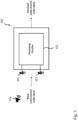
- FIG. 1 shows a schematic diagram illustrating an audio processing apparatus 100 according to an embodiment.
- the audio processing apparatus 100 which could be implemented, for instance, as a mobile phone, a phone conference system or the like, comprises a plurality of spatially separated audio sensors, in particular microphones 101 and processing circuitry.
- the processing circuitry may comprise hardware and software.
- the hardware may comprise digital circuitry, or both analog and digital circuitry.
- Digital circuitry may comprise components such as application-specific integrated circuits (ASICs), field-programmable arrays (FPGAs), digital signal processors (DSPs), or general-purpose processors.
- the processing circuitry comprises one or more processors and a non-transitory memory connected to the one or more processors.
- the non-transitory memory may carry executable program code which, when executed by the one or more processors, causes the apparatus to perform the operations or methods described herein.
- the processing circuitry is a processor 103.
- Each audio sensor 101 is configured to receive a respective plurality of audio frames or segments of an audio signal, for instance, speech from an audio source 105, wherein the respective plurality of audio frames defines an audio channel of the audio signal from the audio source 105.
- the two exemplary audio sensors 101 shown in figure 1 receive a first channel and a second channel of the audio signal from the audio source 105, respectively.
- one of the two exemplary audio sensors 101 shown in figure 1 is closer to the audio source 105 than the other one.
- the processing circuitry 103 of the audio processing apparatus 100 is configured to determine, i.e. extract a respective feature set having at least one feature for each audio frame of each of the plurality of audio frames.
- the respective feature set for each audio frame of each of the plurality of audio frames comprises a spectral representation, in particular a log spectrum of the audio frame.
- all audio signals can be processed by a STFT, using 25ms audio frames shifted by 10ms, to extract the spectrum of each recorded audio signal channel, which define the features of the feature sets. As already described above, the spectrum extraction is done for each channel separately.
- the plurality of features of the different feature sets define a three-dimensional feature array 201.
- the three-dimensional feature array 201 has a dimension corresponding to time represented by a time stamp t, a dimension corresponding to frequency f and a dimension corresponding to the audio channel c.
- the processing circuitry 103 of the audio processing apparatus 100 is further configured to process the three-dimensional feature array 201 using a neural network (herein also referred to as "rotational self-attention block”), wherein the neural network comprises a self-attention layer configured to process a plurality of two-dimensional sub-arrays 203a-c of the three-dimensional feature array 201.
- a neural network herein also referred to as "rotational self-attention block”
- the neural network comprises a self-attention layer configured to process a plurality of two-dimensional sub-arrays 203a-c of the three-dimensional feature array 201.
- figure 2 shows six two-dimensional sub-arrays 203a-c of the three-dimensional feature array 201, namely a first and a second two-dimensional sub-array 203a for a respective given time stamp t, a first and a second two-dimensional sub-array 203c for a respective given frequency f and a first and a second two-dimensional sub-array 203b for a respective given audio channel c.
- each of these two-dimensional sub-arrays 203a-c of the three-dimensional feature array 201 is processed by the self-attention layer of the neural network implemented by the processing circuitry 103 of the audio processing apparatus 100 into a respective processed two-dimensional sub-array 203a'-c'.
- the processing circuitry 103 of the audio processing apparatus 100 is configured to generate a denoised single-channel output signal on the basis of the plurality of processed two-dimensional sub-arrays 203a'-c'.
- the processing circuitry 103 is configured to generate the output signal on the basis of the plurality of processed two-dimensional sub-arrays 203a'-c' by mixing the plurality of audio channels on the basis of a plurality of channel weights, time stamp weights and/or frequency weights.
- the neural network including the self-attention layer is configured to process the plurality of two-dimensional sub-arrays 203a-c of the three-dimensional feature array 201 into the processed two-dimensional sub-arrays 203a'-c' and, subsequently, into a processed three-dimensional feature array 205, wherein the processing circuitry 103 of the audio processing apparatus 100 is configured to generate the denoised single-channel output signal on the basis of the processed three-dimensional feature array 205.
- the audio processing apparatus 100 illustrated in figures 1 to 3 can be considered to comprise a multi-channel enhancing subnetwork that mixes the plurality of audio channels into a single audio channel and a single channel denoising network.
- a main component of the audio processing apparatus 100 is the rotational self-attention block illustrated in figure 2 .
- the rotational self-attention block is comprised of 6 applications of the self-attention layer illustrated in figure 3 .
- the self-attention layer can be implemented similar or identical to self-attention layers of neural networks known from neural machine translation, generating models in computer vision or video classification.
- Each row of the matrix A can be normalized using a softmax normalization to get a new matrix A' of shape [locations ⁇ locations], as defined by the following equation:
- the matrix B can be the processed two-dimensional sub-array 203a' based on the original two-dimensional sub-array 203a corresponding to the matrix x.
- the self-attention block illustrated in figure 2 takes an array of locations (i.e. the three-dimensional feature array 201), each represented by a number of features, and creates a new representation for each location.
- the new representation for a given location is created by attending to all other locations and extracting the relevant information from them for the representation of the given location.
- the locations are not interpreted physical locations, but as the time, frequency, channel bins in a multi-channel spectrogram, i.e. the three-dimensional feature array 201.
- the different frequencies f can be regarded as locations, each represented by the different channels c.
- a new representation for each frequency component f can be created by attending to all other frequencies (represented by their channels c).
- the different channels c can be regarded as locations, each represented by the different frequencies f.
- a new representation can be created for each channel c, by attending to all other channels (represented by their frequencies f).
- the different time stamps t can be regarded as locations, each represented by the different channels c.
- a new representation can be created for each time stamp t, by attending to all other time stamps (represented by their channels c).
- the different time channels c can be regarded as locations, each represented by the different time stamps t.
- a new representation can be created for each channel c, by attending to all other channels (represented by their time stamps t).
- the different frequencies f can be regarded as locations, each represented by the time stamps t.
- a new representation for each frequency component f can be created by attending to all other frequencies (represented by their time stamps t).
- the different time stamps t can be regarded as locations, each represented by the different frequencies f.
- a new representation can be created for each time stamp t by attending to all other time stamps t (represented by their frequencies f).
- the representation of the multichannel audio i.e. the three-dimensional feature array 201 has the shape [time ⁇ frequencies ⁇ channels].
- the self-attention block shown in figure 3 is applied 6 times (applying the necessary transposition to the three-dimensional feature array 201). More specifically, for each two-dimensional sub-array of shape [frequencies ⁇ channels]; for each two-dimensional sub-array of shape [channels ⁇ frequencies]; for each two-dimensional sub-array of shape [time ⁇ channels]; for each two-dimensional sub-array of shape [channels ⁇ time]; for each two-dimensional sub-array of shape [time ⁇ frequencies]; and for each two-dimensional sub-array of shape [frequencies ⁇ time].
- each of the 6 resulting sub-arrays 203a'-c' is transposed back to the shape [time ⁇ frequencies ⁇ channels] and all the results are added to obtain the processed three-dimensional feature array 205 as the output of the rotational self-attention block illustrated in figure 2 .
- Figure 4 shows a schematic diagram illustrating an example of processing blocks implemented in the audio processing apparatus 100 according to an embodiment in a training stage
- figure 5 shows a schematic diagram illustrating an example of processing blocks implemented in the audio processing apparatus according to an embodiment in an application stage.
- the neural network implemented by the processing circuitry 103 of the audio processing apparatus 100 is trained using two inputs, namely (i) a (known) multi-channel noisy audio signal, for instance, speech segment and (ii) the clean, i.e. denoised audio signal, for instance, speech.
- the processing block 403, 503 of figures 4 and 5 can comprise that the rotational self-attention block is applied three times, such that a rectified non-linearity can be applied after the first and the second rotational self-attention blocks.
- a softmax function can be applied during the third rotational self-attention block of processing blocks 403, 503.
- the output of the last rotational self-attention block of the processing blocks 403, 503 is a matrix D of shape [time ⁇ frequencies ⁇ channels].
- the result S is the enhanced single channel noisy audio signal, i.e. segment.
- a residual block is comprised of two parallel paths.
- the first path contains two convolutional layers applied one after another, where batch normalization and a rectified-linear non-linearity are applied in between the layers.
- the second path contains just the identity function.
- the output of the two paths are summed, and a rectified-linear non-linearity is applied.
- the output of the processing blocks 407, 507 is the enhancement mask for one channel.
- the resulting output is attended across all spatial location into a single vector having, for instance, 13,312 entries.
- the vector is processed through a fully connected layer with, for instance, 201 output units.
- These exemplary 201 values are treated as a denoising mask and are added to the central frame of the noisy speech window.
- the result is the denoised frame, and the output of the neural network implemented by the processing circuitry 103 of the audio processing apparatus 100 according to an embodiment.
- the resulting network contains almost 18,000,000 trainable parameters (as calculated by "Tensorflow" according to the accumulative size of each weight and bias tensor).
- the weight matrix of a convolutional layer is of shape [kernel width, kernel length, input channels, outputs channels], and is trained to minimize the mean squared error between the denoised and clean frames (see processing block 411 of figure 4 ).
- optimization is done using a stochastic gradient descent with a learning rate of, for instance, 0.01 and a minibatch size of, for instance, 64 windows.
- the parameters of the enhancement subnetwork are restored from a pretrained model for single-channel enhancement, and they are fine-tuned at the same time as the parameters for the enhancement subnetwork are being learned.
- a L2 loss is computing the difference between the enhanced and the clean spectrums (see processing block 411 of figure 4 ).
- all model parameters are optimized simultaneously using a gradient-based optimization algorithm.
- an additional phase can be extracted from a selected channel of the noisy multichannel audio signal, in particular the channel closest to the audio source 105.
- the phase is then used together with the enhanced spectrum to reconstruct a single channel enhanced audio signal, i.e. waveform (see processing block 511 of figure 5 ).
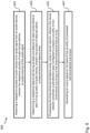
- Figure 6 shows a flow diagram illustrating an example of a corresponding audio processing method 600 according to an embodiment.
- the audio processing method 600 can be performed by the audio processing apparatus 100 described above and below.
- the audio processing method 600 comprises the following steps: a first step 601 of receiving a respective plurality of audio frames of an audio signal from the audio source 105, wherein the respective plurality of audio frames defines an audio channel of the audio signal from the audio source 105; a second step 603 of determining, i.e.
- the plurality of features define a three-dimensional feature array 201; a third step 605 of processing the three-dimensional feature array 301 using a neural network, wherein the neural network comprises a self-attention layer configured to process a plurality of two-dimensional sub-arrays 203a-c of the three-dimensional feature array 201; and a fourth step 607 of generating a de-noised single channel output signal on the basis of the plurality of processed two-dimensional sub-arrays 203a'-c' of the three-dimensional feature array 201.
- the neural network was trained for about 4 days and the publicly available pretrained speech recognition scheme known as "Baidu Deep Speech system" was used. For a better analysis of the performance, the following versions of the Librispeech test set have been evaluated.
- denoised enhanced single-channel audio frames have been used, which are the output of the audio processing apparatus 100 according to an embodiment, together with the phase of a selected noisy channel, to reconstruct a waveform (inverse STFT).
- This setting evaluates the performance of the audio processing apparatus 100 according to an embodiment as a whole, including both the enhancing subnetwork and the single-channel denoising subnetwork.
- the enhanced single channel noisy audio (after training the entire neural network) is used together with the phase of a selected noisy channel to reconstruct a waveform. This setting evaluates the contribution of the enhancing subnetwork.
- the pretrained single-channel denoiser is run on a selected channel and fine-tuned on the trained data. This setting evaluates the contribution of the single-channel denoising subnetwork.
- a baseline filter-and-sum beamformer is used, for instance the publically available "Beamformlt” (https://qithub.com/xanquera/Beamformlt ).
- the denoised enhanced single-channel audio frames are used together with the phase of a selected noisy channel to reconstruct a waveform (inverse STFT), where the rotational self-attention block is applied only once, instead of three times.
- Figure 7 shows a table summarizes the performance of the audio processing apparatus 100 and the audio processing method 600 according to an embodiment with the settings described above using a word error rate, WER, measure.
- the disclosed system, apparatus, and method may be implemented in other manners.
- the described apparatus embodiment is merely exemplary.
- the unit division is merely logical function division and may be other division in actual implementation.
- a plurality of units or components may be combined or integrated into another system, or some features may be ignored or not performed.
- the displayed or discussed mutual couplings or direct couplings or communication connections may be implemented by using some interfaces.
- the indirect couplings or communication connections between the apparatuses or units may be implemented in electronic, mechanical, or other forms.
- the units described as separate parts may or may not be physically separate, and parts displayed as units may or may not be physical units, may be located in one position, or may be distributed on a plurality of network units. Some or all of the units may be selected according to actual needs to achieve the objectives of the solutions of the embodiments.
- functional units in the embodiments of the invention may be integrated into one processing unit, or each of the units may exist alone physically, or two or more units are integrated into one unit.
Landscapes
- Engineering & Computer Science (AREA)
- Physics & Mathematics (AREA)
- Health & Medical Sciences (AREA)
- Computational Linguistics (AREA)
- Theoretical Computer Science (AREA)
- Signal Processing (AREA)
- Acoustics & Sound (AREA)
- Multimedia (AREA)
- Human Computer Interaction (AREA)
- Audiology, Speech & Language Pathology (AREA)
- Artificial Intelligence (AREA)
- Data Mining & Analysis (AREA)
- Evolutionary Computation (AREA)
- Biophysics (AREA)
- General Physics & Mathematics (AREA)
- Mathematical Physics (AREA)
- Software Systems (AREA)
- General Engineering & Computer Science (AREA)
- Computing Systems (AREA)
- Molecular Biology (AREA)
- General Health & Medical Sciences (AREA)
- Biomedical Technology (AREA)
- Life Sciences & Earth Sciences (AREA)
- Quality & Reliability (AREA)
- Spectroscopy & Molecular Physics (AREA)
- Stereophonic System (AREA)
Description
- The present invention relates to audio processing. More specifically, the invention relates to an audio processing apparatus and method for denoising a multi-channel audio signal.
- There have been some attempts of denoising a multi-channel audio signal, i.e. an audio signal detected by a plurality of audio sensors, using neural networks, for instance, in speech recognition applications. In some of these known approaches a recurrent neural network is used to estimate the mixing coefficients of the different channels of the audio channels and to perform denoising using the mixing coefficients.
- Although the known approaches already provide some advantages, there is still a need for an improved audio processing apparatus and method for denoising a multi-channel audio signal.
- "Multi-channel attention for end-to-end speech recognition", S Braun et al. (2018), disclose an attention mechanism for multi-channel speech recognition. In particular, the attention mechanism is invariant to the channel ordering by evaluating each channel independently.
- "Multi-level Stereo Attention Model for Center Channel Extraction", LIM WOOTAEK et al. (2019) discloses a stereo attention network for extracting sound sources from multi-channel audio.
- "Attention Is All You Need", ASHISH VASWANI et al. (2017), discloses a self-attention based "Transformer" as a sequence transduction model, which does not require recurrent or convolutional neural networks.
- It is an object of the invention to provide an improved audio processing apparatus and method allowing for an improved enhancement of a noisy multi-channel audio signal.
- The foregoing and other objects are achieved by the subject matter of the independent claims. Further implementation forms and embodiments are apparent from the dependent claims, the description and the figures.
- Generally, implementation forms and embodiments of the invention are based on the idea of combining multi-channel enhancing and denoising into one model. First, the model computes channel mixing weights for each time-frequency component of a multi-channel audio signal, then mixes all channels using the mixing weights and, finally, denoises the resulting single channel. In contrast to previous conventional approaches, which employ a recurrent neural network to estimate the mixing coefficients of the different channels of an audio signal, implementation forms and embodiments of the invention make use of a novel self-attention mechanism that represents every time-frequency bin of a multi-channel audio signal in every channel in a manner that is aware of all time-frequency bins in all other channels. This novel self-attention mechanism allows representing each time-frequency bin for each channel in a manner that is aware of all other time-frequency bins in all channels. Thus, the novel self-attention mechanism employed by embodiments of the invention attends to other locations in the input data, while representing other locations, which results in a better representation of the multi-channel spectrum.
- More specifically, according to a first aspect the invention relates to an audio processing apparatus, comprising a plurality of spatially separated audio sensors, wherein each audio sensor is configured to receive a respective plurality of audio frames of an audio signal from an audio source, wherein the respective plurality of audio frames defines an audio channel of the audio signal from the audio source. Moreover, the audio processing apparatus comprises processing circuitry configured to: determine, i.e. extract a respective feature set having at least one feature for each audio frame of each of the plurality of audio frames in each channel, wherein the plurality of features of the feature sets of the channels define a three-dimensional feature array; process the three-dimensional feature array using a neural network (herein also referred to as "rotational self-attention block"), wherein the neural network comprises a self-attention layer configured to process a plurality of two-dimensional sub-arrays of the three-dimensional feature array; and generate a denoised single-channel output signal on the basis of the plurality of processed two-dimensional sub-arrays.
- In a further possible implementation form of the first aspect, the respective feature set for each audio frame of each of the plurality of audio frames in each channel comprises a spectral representation, in particular a log spectrum of the audio frame.
- In a further possible implementation form of the first aspect, the three-dimensional feature array has a dimension corresponding to time represented by a time stamp, a dimension corresponding to frequency and a dimension corresponding to the audio channel.
- In a further possible implementation form of the first aspect, the two-dimensional sub-arrays of the three-dimensional feature array comprise one or more two-dimensional sub-arrays for a given time stamp, one or more two-dimensional sub-arrays for a given frequency and/or one or more two-dimensional sub-arrays for a given audio channel.
- In a further possible implementation form of the first aspect, the processing circuitry is configured to generate the output signal on the basis of the plurality of processed two-dimensional sub-arrays by mixing the plurality of audio channels on the basis of a plurality of channel weights, time stamp weights and/or frequency weights.
- In a further possible implementation form of the first aspect, the processing circuitry is configured to determine the plurality of channel weights by applying a normalization over the plurality of audio channels.
- In a further possible implementation form of the first aspect, the processing circuitry is further configured to generate a denoising mask on the basis of the mixed audio channels.
- In a further possible implementation form of the first aspect, the processing circuitry is further configured to apply the denoising mask to the mixed audio channels for generating the output signal.
- In a further possible implementation form of the first aspect, the neural network is configured to process the plurality of two-dimensional sub-arrays of the three-dimensional feature array into a processed three-dimensional feature array, wherein the processing circuitry is configured to generate the denoised single-channel output signal on the basis of the processed three-dimensional feature array.
- In a further possible implementation form of the first aspect, the processing circuitry is configured to train the self-attention layer on the basis of a plurality of pairs of noisy multi-channel training audio signals and clean single channel training output signals.
- In a further possible implementation form of the first aspect, the processing circuitry is configured to train the self-attention layer by minimizing a difference measure, in particular the L2 loss between a spectral representation, in particular a log spectrum of the output signal generated by the processing circuitry on the basis of a respective training audio signal and a spectral representation, in particular a log spectrum of a respective training output signal. In an embodiment, the processing circuitry is configured to minimize the difference measure using a gradient-based optimization algorithm.
- In a further possible implementation form of the first aspect, the processing circuitry is configured to extract phase information from one of the plurality of audio channels and to generate the output signal on the basis of the plurality of processed two-dimensional sub-arrays and the extracted phase information.
- In a further possible implementation form of the first aspect, the processing circuitry is configured to determine the audio sensor closest to the audio source and to extract the phase information from the audio channel defined by the audio sensor closest to the audio source for generating the output signal.
- According to a second aspect the invention relates to a corresponding audio processing method, comprising the steps of: receiving from each of a plurality of sensors a respective plurality of audio frames of an audio signal from an audio source, wherein the respective plurality of audio frames defines an audio channel of the audio signal from the audio source; determining, i.e. extracting a respective feature set having at least one feature for each audio frame of each of the plurality of audio frames in each channel, wherein the plurality of features of the feature sets of the channels define a three-dimensional feature array; processing the three-dimensional feature array using a neural network, wherein the neural network comprises a self-attention layer configured to process a plurality of two-dimensional sub-arrays of the three-dimensional feature array; and generating a de-noised single channel output signal on the basis of the plurality of processed two-dimensional sub-arrays of the three-dimensional feature array.
- The audio processing method according to the second aspect of the invention can be performed by the audio processing apparatus according to the first aspect of the invention. Further features of the audio processing method according to the second aspect of the invention result directly from the functionality of the audio processing apparatus according to the first aspect of the invention and its different implementation forms described above and below.
- According to a third aspect the invention relates to a computer program comprising program code for performing the audio processing method according to the second aspect, when executed on a processor or a computer.
- The invention can be implemented in hardware and/or software.
- Further embodiments of the invention will be described with respect to the following figures, wherein:
-
Fig. 1 shows a schematic diagram illustrating an audio processing apparatus according to an embodiment; -
Fig. 2 shows a schematic diagram illustrating processing steps implemented in an audio processing apparatus according to an embodiment; -
Fig. 3 shows a schematic diagram illustrating a self-attention layer of a neural network implemented in an audio processing apparatus according to an embodiment; -
Fig. 4 shows a schematic diagram illustrating an example of processing blocks implemented in an audio processing apparatus according to an embodiment in a training phase; -
Fig. 5 shows a schematic diagram illustrating an example of processing blocks implemented in an audio processing apparatus according to an embodiment in an application phase; -
Fig. 6 shows a flow diagram illustrating an example of an audio processing method according to an embodiment; and -
Fig. 7 shows a table illustrating the performance of an audio processing apparatus and method according to an embodiment. - In the various figures, identical reference signs will be used for identical or at least functionally equivalent features.
- In the following description, reference is made to the accompanying drawings, which form part of the disclosure, and in which are shown, by way of illustration, specific aspects in which the invention may be placed. It is understood that other aspects may be utilized and structural or logical changes may be made without departing from the scope of the invention. The following detailed description, therefore, is not to be taken in a limiting sense, as the scope of the invention is defined by the appended claims.
- For instance, it is understood that a disclosure in connection with a described method may also hold true for a corresponding device or system configured to perform the method and vice versa. For example, if a specific method step is described, a corresponding device may include a unit to perform the described method step, even if such unit is not explicitly described or illustrated in the figures. Further, it is understood that the features of the various exemplary aspects described herein may be combined with each other, unless specifically noted otherwise.
-
Figure 1 shows a schematic diagram illustrating anaudio processing apparatus 100 according to an embodiment. Theaudio processing apparatus 100, which could be implemented, for instance, as a mobile phone, a phone conference system or the like, comprises a plurality of spatially separated audio sensors, inparticular microphones 101 and processing circuitry. The processing circuitry may comprise hardware and software. The hardware may comprise digital circuitry, or both analog and digital circuitry. Digital circuitry may comprise components such as application-specific integrated circuits (ASICs), field-programmable arrays (FPGAs), digital signal processors (DSPs), or general-purpose processors. In one embodiment, the processing circuitry comprises one or more processors and a non-transitory memory connected to the one or more processors. The non-transitory memory may carry executable program code which, when executed by the one or more processors, causes the apparatus to perform the operations or methods described herein. In the shown example, the processing circuitry is aprocessor 103. - Each
audio sensor 101 is configured to receive a respective plurality of audio frames or segments of an audio signal, for instance, speech from anaudio source 105, wherein the respective plurality of audio frames defines an audio channel of the audio signal from theaudio source 105. For instance, the twoexemplary audio sensors 101 shown infigure 1 receive a first channel and a second channel of the audio signal from theaudio source 105, respectively. By way of example, one of the twoexemplary audio sensors 101 shown infigure 1 is closer to theaudio source 105 than the other one. - As will be described in more detail further below under further reference to
figures 2 to 5 , theprocessing circuitry 103 of theaudio processing apparatus 100 is configured to determine, i.e. extract a respective feature set having at least one feature for each audio frame of each of the plurality of audio frames. In an embodiment, the respective feature set for each audio frame of each of the plurality of audio frames comprises a spectral representation, in particular a log spectrum of the audio frame. In an embodiment, all audio signals can be processed by a STFT, using 25ms audio frames shifted by 10ms, to extract the spectrum of each recorded audio signal channel, which define the features of the feature sets. As already described above, the spectrum extraction is done for each channel separately. - As illustrated in
figure 2 , the plurality of features of the different feature sets define a three-dimensional feature array 201. In the embodiment shown infigure 2 , the three-dimensional feature array 201 has a dimension corresponding to time represented by a time stamp t, a dimension corresponding to frequency f and a dimension corresponding to the audio channel c. - The
processing circuitry 103 of theaudio processing apparatus 100 is further configured to process the three-dimensional feature array 201 using a neural network (herein also referred to as "rotational self-attention block"), wherein the neural network comprises a self-attention layer configured to process a plurality of two-dimensional sub-arrays 203a-c of the three-dimensional feature array 201. By way of example,figure 2 shows six two-dimensional sub-arrays 203a-c of the three-dimensional feature array 201, namely a first and a second two-dimensional sub-array 203a for a respective given time stamp t, a first and a second two-dimensional sub-array 203c for a respective given frequency f and a first and a second two-dimensional sub-array 203b for a respective given audio channel c. As illustrated infigures 2 and3 , each of these two-dimensional sub-arrays 203a-c of the three-dimensional feature array 201 is processed by the self-attention layer of the neural network implemented by theprocessing circuitry 103 of theaudio processing apparatus 100 into a respective processed two-dimensional sub-array 203a'-c'. - Moreover, the
processing circuitry 103 of theaudio processing apparatus 100 is configured to generate a denoised single-channel output signal on the basis of the plurality of processed two-dimensional sub-arrays 203a'-c'. In an embodiment, theprocessing circuitry 103 is configured to generate the output signal on the basis of the plurality of processed two-dimensional sub-arrays 203a'-c' by mixing the plurality of audio channels on the basis of a plurality of channel weights, time stamp weights and/or frequency weights. - As illustrated in
figure 2 , the neural network including the self-attention layer is configured to process the plurality of two-dimensional sub-arrays 203a-c of the three-dimensional feature array 201 into the processed two-dimensional sub-arrays 203a'-c' and, subsequently, into a processed three-dimensional feature array 205, wherein theprocessing circuitry 103 of theaudio processing apparatus 100 is configured to generate the denoised single-channel output signal on the basis of the processed three-dimensional feature array 205. - Thus, the
audio processing apparatus 100 illustrated infigures 1 to 3 can be considered to comprise a multi-channel enhancing subnetwork that mixes the plurality of audio channels into a single audio channel and a single channel denoising network. As already described above, a main component of theaudio processing apparatus 100 is the rotational self-attention block illustrated infigure 2 . In the embodiment shown infigure 2 , the rotational self-attention block is comprised of 6 applications of the self-attention layer illustrated infigure 3 . According to embodiments of the invention, the self-attention layer can be implemented similar or identical to self-attention layers of neural networks known from neural machine translation, generating models in computer vision or video classification. - In the following a possible implementation of the self-attention layer of the neural network implemented by the
processing circuitry 103 of theaudio processing apparatus 100 will be described in more detail under particular reference tofigure 3 . - Given a matrix x of shape [locations × features], three learnable linear transformations are applied to this matrix to obtain a query matrix Q, a key matrix K, and a value matrix V defined by the following equations:

- Thereafter, the inner product of each row in the query matrix with every row in the key matrix can be computed to get an attention weights matrix A of shape [locations × locations] as defined by the following equation:

- Each row of the matrix A can be normalized using a softmax normalization to get a new matrix A' of shape [locations × locations], as defined by the following equation:

- Thereafter, each row in the attention weight matrix can be used weights in a weighted sum of the values matrix, eventually getting the self-attention output matrix B of shape [locations× features], as defined by the following equation:
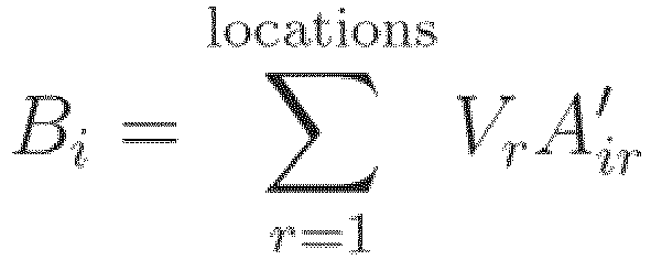
- Here Bi denotes row i of the matrix B and Vr denotes row r of the matrix V. As illustrated in
figure 3 , the matrix B can be the processed two-dimensional sub-array 203a' based on the original two-dimensional sub-array 203a corresponding to the matrix x. - As already described above, the self-attention block illustrated in
figure 2 takes an array of locations (i.e. the three-dimensional feature array 201), each represented by a number of features, and creates a new representation for each location. The new representation for a given location is created by attending to all other locations and extracting the relevant information from them for the representation of the given location. In an embodiment, there are 3 axes: time, frequencies and channels. Each of them can be regarded as locations axis or features axis. The locations are not interpreted physical locations, but as the time, frequency, channel bins in a multi-channel spectrogram, i.e. the three-dimensional feature array 201. - As illustrated in
figure 2 , for a given time stamp t, the different frequencies f can be regarded as locations, each represented by the different channels c. A new representation for each frequency component f can be created by attending to all other frequencies (represented by their channels c). - As illustrated in
figure 2 , for a given time stamp t, the different channels c can be regarded as locations, each represented by the different frequencies f. A new representation can be created for each channel c, by attending to all other channels (represented by their frequencies f). - As illustrated in
figure 2 , for a given frequency f, the different time stamps t can be regarded as locations, each represented by the different channels c. A new representation can be created for each time stamp t, by attending to all other time stamps (represented by their channels c). - As illustrated in
figure 2 , for a given frequency f, the different time channels c can be regarded as locations, each represented by the different time stamps t. A new representation can be created for each channel c, by attending to all other channels (represented by their time stamps t). - As illustrated in
figure 2 , for a given channel c, the different frequencies f can be regarded as locations, each represented by the time stamps t. A new representation for each frequency component f can be created by attending to all other frequencies (represented by their time stamps t). - As illustrated in
figure 2 , for a given channel c, the different time stamps t can be regarded as locations, each represented by the different frequencies f. A new representation can be created for each time stamp t by attending to all other time stamps t (represented by their frequencies f). - Thus, in the embodiment illustrated in
figure 2 the representation of the multichannel audio, i.e. the three-dimensional feature array 201 has the shape [time × frequencies × channels]. The self-attention block shown infigure 3 is applied 6 times (applying the necessary transposition to the three-dimensional feature array 201). More specifically, for each two-dimensional sub-array of shape [frequencies × channels]; for each two-dimensional sub-array of shape [channels × frequencies]; for each two-dimensional sub-array of shape [time × channels]; for each two-dimensional sub-array of shape [channels × time]; for each two-dimensional sub-array of shape [time × frequencies]; and for each two-dimensional sub-array of shape [frequencies × time]. - In an embodiment, each of the 6 resulting sub-arrays 203a'-c' is transposed back to the shape [time × frequencies× channels] and all the results are added to obtain the processed three-
dimensional feature array 205 as the output of the rotational self-attention block illustrated infigure 2 . -
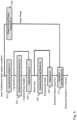
Figure 4 shows a schematic diagram illustrating an example of processing blocks implemented in theaudio processing apparatus 100 according to an embodiment in a training stage, whilefigure 5 shows a schematic diagram illustrating an example of processing blocks implemented in the audio processing apparatus according to an embodiment in an application stage. As will be appreciated, some of the processing bocks illustrated infigures 4 and5 already have been described above, such as the spectrum extraction processing blocks 401, 402, 501. In the training stage shown infigure 4 , the neural network implemented by theprocessing circuitry 103 of theaudio processing apparatus 100 according to an embodiment is trained using two inputs, namely (i) a (known) multi-channel noisy audio signal, for instance, speech segment and (ii) the clean, i.e. denoised audio signal, for instance, speech. - In an embodiment, the
processing block figures 4 and5 can comprise that the rotational self-attention block is applied three times, such that a rectified non-linearity can be applied after the first and the second rotational self-attention blocks. In an embodiment, a softmax function can be applied during the third rotational self-attention block of processing blocks 403, 503. - As already described above, in an embodiment, the output of the last rotational self-attention block of the processing blocks 403, 503 is a matrix D of shape [time × frequencies ×channels]. In an embodiment, to create the channel mixing weights for each time-frequency bin a softmax normalization can be applied on the channels axis as defined by the following equation:

- This results in mixing channels that sum to 1 for each time-frequency bin. The output of the STFT for channel k, which is denoted as Ck, has a shape of [time × frequencies], and in an embodiment the channels are mixed according to the mixing weights as defined by the following equation (corresponding to processing
blocks figures 4 and5 , respectively):
- The result S is the enhanced single channel noisy audio signal, i.e. segment.
- As illustrated by the processing blocks 407, 507 of
figures 4 and5 , the enhanced noisy audio is being processed through a series of residual blocks. In an embodiment, a residual block is comprised of two parallel paths. The first path contains two convolutional layers applied one after another, where batch normalization and a rectified-linear non-linearity are applied in between the layers. The second path contains just the identity function. The output of the two paths are summed, and a rectified-linear non-linearity is applied. The output of the processing blocks 407, 507 is the enhancement mask for one channel. - In processing blocks 409, 509 of
figures 4 and5 the enhancement mask is then added to the spectrum of enhanced noisy speech in order to obtain the enhanced spectrum. The following table summarizes some exemplary kernel sizes, strides and number of feature maps for each residual block for the speech segment processing:Block ID Kernel Size Stride Feature Maps 1 4x4 1x1 64 2 4x4 1x1 64 3 4x4 2x2 128 4 4x4 1x1 128 5 3x3 2x2 256 6 3x3 1x1 256 7 3x3 2x2 512 8 3x3 1x1 512 - In a final processing stage, the resulting output is attended across all spatial location into a single vector having, for instance, 13,312 entries. The vector is processed through a fully connected layer with, for instance, 201 output units. These exemplary 201 values are treated as a denoising mask and are added to the central frame of the noisy speech window. The result is the denoised frame, and the output of the neural network implemented by the
processing circuitry 103 of theaudio processing apparatus 100 according to an embodiment. In an embodiment, the resulting network contains almost 18,000,000 trainable parameters (as calculated by "Tensorflow" according to the accumulative size of each weight and bias tensor). In an embodiment, the weight matrix of a convolutional layer is of shape [kernel width, kernel length, input channels, outputs channels], and is trained to minimize the mean squared error between the denoised and clean frames (see processing block 411 offigure 4 ). In an embodiment, optimization is done using a stochastic gradient descent with a learning rate of, for instance, 0.01 and a minibatch size of, for instance, 64 windows. At training time, the parameters of the enhancement subnetwork are restored from a pretrained model for single-channel enhancement, and they are fine-tuned at the same time as the parameters for the enhancement subnetwork are being learned. - In an embodiment, a L2 loss is computing the difference between the enhanced and the clean spectrums (see processing block 411 of
figure 4 ). In an embodiment, all model parameters are optimized simultaneously using a gradient-based optimization algorithm. - As illustrated by processing
block 502 offigure 5 , in the application stage an additional phase can be extracted from a selected channel of the noisy multichannel audio signal, in particular the channel closest to theaudio source 105. The phase is then used together with the enhanced spectrum to reconstruct a single channel enhanced audio signal, i.e. waveform (see processing block 511 offigure 5 ). -
Figure 6 shows a flow diagram illustrating an example of a correspondingaudio processing method 600 according to an embodiment. In an embodiment, theaudio processing method 600 can be performed by theaudio processing apparatus 100 described above and below. - The
audio processing method 600 comprises the following steps: afirst step 601 of receiving a respective plurality of audio frames of an audio signal from theaudio source 105, wherein the respective plurality of audio frames defines an audio channel of the audio signal from theaudio source 105; asecond step 603 of determining, i.e. extracting a respective feature set having at least one feature for each audio frame of each of the plurality of audio frames, wherein the plurality of features define a three-dimensional feature array 201; athird step 605 of processing the three-dimensional feature array 301 using a neural network, wherein the neural network comprises a self-attention layer configured to process a plurality of two-dimensional sub-arrays 203a-c of the three-dimensional feature array 201; and afourth step 607 of generating a de-noised single channel output signal on the basis of the plurality of processed two-dimensional sub-arrays 203a'-c' of the three-dimensional feature array 201. - In the following, some results illustrating the performance of the
audio processing apparatus 100 according to an embodiment and theaudio processing method 600 according to an embodiment will be described in more detail. - For evaluating the
audio processing apparatus 100 according to an embodiment and theaudio processing method 600 according to an embodiment the neural network was trained for about 4 days and the publicly available pretrained speech recognition scheme known as "Baidu Deep Speech system" was used. For a better analysis of the performance, the following versions of the Librispeech test set have been evaluated. - Firstly, denoised enhanced single-channel audio frames have been used, which are the output of the
audio processing apparatus 100 according to an embodiment, together with the phase of a selected noisy channel, to reconstruct a waveform (inverse STFT). This setting evaluates the performance of theaudio processing apparatus 100 according to an embodiment as a whole, including both the enhancing subnetwork and the single-channel denoising subnetwork. - Secondly, the enhanced single channel noisy audio (after training the entire neural network) is used together with the phase of a selected noisy channel to reconstruct a waveform. This setting evaluates the contribution of the enhancing subnetwork.
- The pretrained single-channel denoiser is run on a selected channel and fine-tuned on the trained data. This setting evaluates the contribution of the single-channel denoising subnetwork.
- Moreover, a baseline filter-and-sum beamformer is used, for instance the publically available "Beamformlt" (https://qithub.com/xanquera/Beamformlt).
- Finally, the denoised enhanced single-channel audio frames, already used above, are used together with the phase of a selected noisy channel to reconstruct a waveform (inverse STFT), where the rotational self-attention block is applied only once, instead of three times.
-
Figure 7 shows a table summarizes the performance of theaudio processing apparatus 100 and theaudio processing method 600 according to an embodiment with the settings described above using a word error rate, WER, measure. - The person skilled in the art will understand that the "blocks" ("units") of the various figures (method and apparatus) represent or describe functionalities of embodiments of the invention (rather than necessarily individual "units" in hardware or software) and thus describe equally functions or features of apparatus embodiments as well as method embodiments (unit = step).
- In the several embodiments provided in the present application, it should be understood that the disclosed system, apparatus, and method may be implemented in other manners. For example, the described apparatus embodiment is merely exemplary. For example, the unit division is merely logical function division and may be other division in actual implementation. For example, a plurality of units or components may be combined or integrated into another system, or some features may be ignored or not performed. In addition, the displayed or discussed mutual couplings or direct couplings or communication connections may be implemented by using some interfaces. The indirect couplings or communication connections between the apparatuses or units may be implemented in electronic, mechanical, or other forms.
- The units described as separate parts may or may not be physically separate, and parts displayed as units may or may not be physical units, may be located in one position, or may be distributed on a plurality of network units. Some or all of the units may be selected according to actual needs to achieve the objectives of the solutions of the embodiments.
- In addition, functional units in the embodiments of the invention may be integrated into one processing unit, or each of the units may exist alone physically, or two or more units are integrated into one unit.
Claims (15)
- An audio processing apparatus (100), comprising:a plurality of audio sensors (101), each audio sensor (101) configured to receive a respective plurality of audio frames of an audio signal from an audio source (105), wherein the respective plurality of audio frames defines an audio channel of the audio signal; and characterized bya processing circuitry (103) configured to:determine a respective feature set having at least one feature for each audio frame of each of the plurality of audio frames in each channel, wherein the plurality of features of the feature sets of the channels define a three-dimensional feature array (201);process the three-dimensional feature array (201) using a neural network, wherein the neural network comprises a self-attention layer configured to process a plurality of two-dimensional sub-arrays (203a-c) of the three-dimensional feature array (201); andgenerate a denoised output audio signal on the basis of the plurality of processed two-dimensional sub-arrays (203a'-c').
- The audio processing apparatus (100) of claim 1, wherein the respective feature set for each audio frame of each of the plurality of audio frames in each channel comprises a spectral representation of the audio frame.
- The audio processing apparatus (100) of claim 1 or 2, wherein the three-dimensional feature array (201) has a dimension corresponding to time represented by a time stamp, a dimension corresponding to frequency and a dimension corresponding to the audio channel.
- The audio processing apparatus (100) of claim 3, wherein the two-dimensional sub-arrays comprise one or more two-dimensional sub-arrays for a given time stamp (203a), one or more two-dimensional sub-arrays for a given frequency (203c) and/or one or more two-dimensional sub-arrays for a given audio channel (203b).
- The audio processing apparatus (100) of any one of the preceding claims, wherein the processing circuitry (103) is configured to generate the output signal on the basis of the plurality of processed two-dimensional sub-arrays (203a'-c') by mixing the plurality of audio channels on the basis of a plurality of channel weights, time stamp weights and/or frequency weights.
- The audio processing apparatus (100) of claim 5, wherein the processing circuitry (103) is configured to determine the plurality of channel weights by applying a normalization over the plurality of audio channels.
- The audio processing apparatus (100) of claim 5 or 6, wherein the processing circuitry (103) is further configured to generate a denoising mask on the basis of the mixed audio channels.
- The audio processing apparatus (100) of claim 7, wherein the processing circuitry (103) is further configured to apply the denoising mask to the mixed audio channels for generating the output signal.
- The audio processing apparatus (100) of any one of the preceding claims, wherein the neural network is configured to process the plurality of two-dimensional sub-arrays (203a-c) of the three-dimensional feature array (201) into a processed three-dimensional feature array (205) and wherein the processing circuitry (103) is configured to generate the output signal on the basis of the processed three-dimensional feature array (205).
- The audio processing apparatus (100) of any one of the preceding claims, wherein the processing circuitry (103) is configured to train the self-attention layer on the basis of a plurality of pairs of training audio signals and training output signals.
- The audio processing apparatus (100) of claim 10, wherein the processing circuitry (103) is configured to train the self-attention layer by minimizing a difference measure between a spectral representation of the output signal generated by the processing circuitry (103) on the basis of a respective training audio signal and a spectral representation of a respective training output signal.
- The audio processing apparatus (100) of any one of the preceding claims, wherein the processing circuitry (103) is configured to extract phase information from one of the plurality of audio channels and to generate the output signal on the basis of the plurality of processed two-dimensional sub-arrays (203a'-c') and the extracted phase information.
- The audio processing apparatus (100) of claim 12, wherein the processing circuitry (103) is configured to determine the audio sensor (101) closest to the audio source (105) and to extract the phase information from the audio channel defined by the audio sensor (101) closest to the audio source (105) for generating the output signal.
- An audio processing method (600), comprising:receiving (601) from each of a plurality of sensors (101) a respective plurality of audio frames of an audio signal from an audio source (105)wherein the respective plurality of audio frames defines an audio channel of the audio signal; and characterized by:determining (603) a respective feature set having at least one feature for each audio frame of each of the plurality of audio frames in each channel, wherein the plurality of features of the feature sets of the channels define a three-dimensional feature array (201);processing (605) the three-dimensional feature array (201) using a neural network, wherein the neural network comprises a self-attention layer configured to process a plurality of two-dimensional sub-arrays (203a-c) of the three-dimensional feature array (201); andgenerating (607) a denoised output audio signal on the basis of the plurality of processed two-dimensional sub-arrays (203a'-c').
- A computer program product comprising a non-transitory computer-readable storage medium carrying program code which causes a computer or a processor to perform the method (600) of claim 14 when the program code is executed by the computer or the processor.
Applications Claiming Priority (1)
| Application Number | Priority Date | Filing Date | Title |
|---|---|---|---|
| PCT/EP2019/069924 WO2021013345A1 (en) | 2019-07-24 | 2019-07-24 | Audio processing apparatus and method for denoising a multi-channel audio signal |
Publications (2)
| Publication Number | Publication Date |
|---|---|
| EP3994690A1 EP3994690A1 (en) | 2022-05-11 |
| EP3994690B1 true EP3994690B1 (en) | 2024-06-19 |
Family
ID=67441134
Family Applications (1)
| Application Number | Title | Priority Date | Filing Date |
|---|---|---|---|
| EP19745121.4A Active EP3994690B1 (en) | 2019-07-24 | 2019-07-24 | Audio processing apparatus and method for denoising a multi-channel audio signal |
Country Status (3)
| Country | Link |
|---|---|
| US (1) | US11889292B2 (en) |
| EP (1) | EP3994690B1 (en) |
| WO (1) | WO2021013345A1 (en) |
Families Citing this family (12)
| Publication number | Priority date | Publication date | Assignee | Title |
|---|---|---|---|---|
| JP7270869B2 (en) * | 2021-04-07 | 2023-05-10 | 三菱電機株式会社 | Information processing device, output method, and output program |
| US12308035B2 (en) | 2021-06-11 | 2025-05-20 | Microsoft Technology Licensing, Llc | System and method for self-attention-based combining of multichannel signals for speech processing |
| GB2609021B (en) | 2021-07-16 | 2024-04-17 | Sony Interactive Entertainment Europe Ltd | Audio generation methods and systems |
| GB2609605B (en) * | 2021-07-16 | 2024-04-17 | Sony Interactive Entertainment Europe Ltd | Audio generation methods and systems |
| US12118787B2 (en) * | 2021-10-12 | 2024-10-15 | Adobe Inc. | Localization of narrations in image data |
| CN116150561B (en) * | 2021-11-15 | 2025-09-02 | 广州视源电子科技股份有限公司 | Processing method, device, and convolutional neural network model for self-attention mechanism |
| CN114171038B (en) * | 2021-12-10 | 2023-07-28 | 北京百度网讯科技有限公司 | Voice noise reduction method, device, equipment and storage medium |
| WO2023183684A1 (en) * | 2022-03-20 | 2023-09-28 | Google Llc | Microphone array configuration invariant, streaming, multichannel neural enhancement frontend for automatic speech recognition |
| CN114842864B (en) * | 2022-04-19 | 2023-05-23 | 电子科技大学 | Short wave channel signal diversity combining method based on neural network |
| US20240412334A1 (en) * | 2023-06-09 | 2024-12-12 | Google Llc | Processor-aware optimizations for on-device acceleration of diffusion models |
| WO2025183943A1 (en) * | 2024-03-01 | 2025-09-04 | Google Llc | Streaming, array-agnostic, full- and sub-band modeling front-end for robust automatic speech recognition |
| CN119993122A (en) * | 2024-12-31 | 2025-05-13 | 中国邮电器材集团有限公司 | Streaming multi-channel end-to-end speech recognition method based on spherical harmonics transform |
-
2019
- 2019-07-24 EP EP19745121.4A patent/EP3994690B1/en active Active
- 2019-07-24 WO PCT/EP2019/069924 patent/WO2021013345A1/en not_active Ceased
-
2022
- 2022-01-21 US US17/581,527 patent/US11889292B2/en active Active
Non-Patent Citations (1)
| Title |
|---|
| GANAPATHY SRIRAM ET AL: "3-D CNN Models for Far-Field Multi-Channel Speech Recognition", 2018 IEEE INTERNATIONAL CONFERENCE ON ACOUSTICS, SPEECH AND SIGNAL PROCESSING (ICASSP), IEEE, 15 April 2018 (2018-04-15), pages 5499 - 5503, XP033400858, DOI: 10.1109/ICASSP.2018.8461580 * |
Also Published As
| Publication number | Publication date |
|---|---|
| US11889292B2 (en) | 2024-01-30 |
| US20220150661A1 (en) | 2022-05-12 |
| WO2021013345A1 (en) | 2021-01-28 |
| EP3994690A1 (en) | 2022-05-11 |
Similar Documents
| Publication | Publication Date | Title |
|---|---|---|
| US11889292B2 (en) | Audio processing apparatus and method for denoising a multi-channel audio signal | |
| Tan et al. | SAGRNN: Self-attentive gated RNN for binaural speaker separation with interaural cue preservation | |
| CN112349297A (en) | Depression detection method based on microphone array | |
| Mimilakis et al. | A recurrent encoder-decoder approach with skip-filtering connections for monaural singing voice separation | |
| EP3440670B1 (en) | Audio source separation | |
| EP4172987A1 (en) | Speech enhancement | |
| He et al. | On the preprocessing and postprocessing of HRTF individualization based on sparse representation of anthropometric features | |
| CN117036884B (en) | Remote sensing image spatiotemporal fusion method based on adaptive normalization and attention mechanism | |
| EP2012555A1 (en) | Signal separating device, signal separating method, information recording medium, and program | |
| CN108364659A (en) | Frequency Domain Convolutional Blind Signal Separation Method Based on Multi-objective Optimization | |
| CN113345465B (en) | Voice separation method, device, equipment and computer readable storage medium | |
| CN108091345A (en) | A kind of ears speech separating method based on support vector machines | |
| CN112085668B (en) | A method of image tone mapping based on region-adaptive self-supervised learning | |
| CN107689223A (en) | Audio identification method and device | |
| CN112201276A (en) | Microphone array speech separation method based on TC-ResNet network | |
| JP6559382B1 (en) | Sound source direction estimating apparatus, sound source direction estimating method, and sound source direction estimating program | |
| CN113314135B (en) | Voice signal identification method and device | |
| CN116994564B (en) | Voice data processing method and processing device | |
| Hu et al. | Head-related transfer function upsampling using an autoencoder-based generative adversarial network with evaluation framework | |
| DE102025100313A1 (en) | Deep learning solution for virtual rotation of binaural audio signals | |
| EP1589783A2 (en) | System and method for separating multiple sources using directional filtering | |
| RU2495504C1 (en) | Method of reducing transmission rate of linear prediction low bit rate voders | |
| Deshpande et al. | Detection of early reflections from a binaural activity map using neural networks | |
| CN113644947A (en) | An adaptive beamforming method, apparatus, device and readable storage medium | |
| JP6129321B2 (en) | Method and apparatus for separating signals by minimum variance spatial filtering under linear constraint conditions |
Legal Events
| Date | Code | Title | Description |
|---|---|---|---|
| STAA | Information on the status of an ep patent application or granted ep patent |
Free format text: STATUS: UNKNOWN |
|
| STAA | Information on the status of an ep patent application or granted ep patent |
Free format text: STATUS: THE INTERNATIONAL PUBLICATION HAS BEEN MADE |
|
| PUAI | Public reference made under article 153(3) epc to a published international application that has entered the european phase |
Free format text: ORIGINAL CODE: 0009012 |
|
| STAA | Information on the status of an ep patent application or granted ep patent |
Free format text: STATUS: REQUEST FOR EXAMINATION WAS MADE |
|
| 17P | Request for examination filed |
Effective date: 20220204 |
|
| AK | Designated contracting states |
Kind code of ref document: A1 Designated state(s): AL AT BE BG CH CY CZ DE DK EE ES FI FR GB GR HR HU IE IS IT LI LT LU LV MC MK MT NL NO PL PT RO RS SE SI SK SM TR |
|
| DAV | Request for validation of the european patent (deleted) | ||
| DAX | Request for extension of the european patent (deleted) | ||
| GRAP | Despatch of communication of intention to grant a patent |
Free format text: ORIGINAL CODE: EPIDOSNIGR1 |
|
| STAA | Information on the status of an ep patent application or granted ep patent |
Free format text: STATUS: GRANT OF PATENT IS INTENDED |
|
| RIC1 | Information provided on ipc code assigned before grant |
Ipc: G10L 21/0216 20130101ALN20231213BHEP Ipc: G06N 3/08 20060101ALI20231213BHEP Ipc: G06N 3/045 20230101ALI20231213BHEP Ipc: G10L 21/0208 20130101AFI20231213BHEP |
|
| INTG | Intention to grant announced |
Effective date: 20240109 |
|
| GRAS | Grant fee paid |
Free format text: ORIGINAL CODE: EPIDOSNIGR3 |
|
| GRAA | (expected) grant |
Free format text: ORIGINAL CODE: 0009210 |
|
| STAA | Information on the status of an ep patent application or granted ep patent |
Free format text: STATUS: THE PATENT HAS BEEN GRANTED |
|
| AK | Designated contracting states |
Kind code of ref document: B1 Designated state(s): AL AT BE BG CH CY CZ DE DK EE ES FI FR GB GR HR HU IE IS IT LI LT LU LV MC MK MT NL NO PL PT RO RS SE SI SK SM TR |
|
| REG | Reference to a national code |
Ref country code: GB Ref legal event code: FG4D |
|
| REG | Reference to a national code |
Ref country code: CH Ref legal event code: EP |
|
| REG | Reference to a national code |
Ref country code: DE Ref legal event code: R096 Ref document number: 602019053886 Country of ref document: DE |
|
| PG25 | Lapsed in a contracting state [announced via postgrant information from national office to epo] |
Ref country code: BG Free format text: LAPSE BECAUSE OF FAILURE TO SUBMIT A TRANSLATION OF THE DESCRIPTION OR TO PAY THE FEE WITHIN THE PRESCRIBED TIME-LIMIT Effective date: 20240619 |
|
| PG25 | Lapsed in a contracting state [announced via postgrant information from national office to epo] |
Ref country code: FI Free format text: LAPSE BECAUSE OF FAILURE TO SUBMIT A TRANSLATION OF THE DESCRIPTION OR TO PAY THE FEE WITHIN THE PRESCRIBED TIME-LIMIT Effective date: 20240619 Ref country code: HR Free format text: LAPSE BECAUSE OF FAILURE TO SUBMIT A TRANSLATION OF THE DESCRIPTION OR TO PAY THE FEE WITHIN THE PRESCRIBED TIME-LIMIT Effective date: 20240619 |
|
| REG | Reference to a national code |
Ref country code: LT Ref legal event code: MG9D |
|
| PG25 | Lapsed in a contracting state [announced via postgrant information from national office to epo] |
Ref country code: GR Free format text: LAPSE BECAUSE OF FAILURE TO SUBMIT A TRANSLATION OF THE DESCRIPTION OR TO PAY THE FEE WITHIN THE PRESCRIBED TIME-LIMIT Effective date: 20240920 |
|
| REG | Reference to a national code |
Ref country code: NL Ref legal event code: MP Effective date: 20240619 |
|
| PG25 | Lapsed in a contracting state [announced via postgrant information from national office to epo] |
Ref country code: LV Free format text: LAPSE BECAUSE OF FAILURE TO SUBMIT A TRANSLATION OF THE DESCRIPTION OR TO PAY THE FEE WITHIN THE PRESCRIBED TIME-LIMIT Effective date: 20240619 |
|
| PG25 | Lapsed in a contracting state [announced via postgrant information from national office to epo] |
Ref country code: NO Free format text: LAPSE BECAUSE OF FAILURE TO SUBMIT A TRANSLATION OF THE DESCRIPTION OR TO PAY THE FEE WITHIN THE PRESCRIBED TIME-LIMIT Effective date: 20240919 Ref country code: LV Free format text: LAPSE BECAUSE OF FAILURE TO SUBMIT A TRANSLATION OF THE DESCRIPTION OR TO PAY THE FEE WITHIN THE PRESCRIBED TIME-LIMIT Effective date: 20240619 Ref country code: HR Free format text: LAPSE BECAUSE OF FAILURE TO SUBMIT A TRANSLATION OF THE DESCRIPTION OR TO PAY THE FEE WITHIN THE PRESCRIBED TIME-LIMIT Effective date: 20240619 Ref country code: GR Free format text: LAPSE BECAUSE OF FAILURE TO SUBMIT A TRANSLATION OF THE DESCRIPTION OR TO PAY THE FEE WITHIN THE PRESCRIBED TIME-LIMIT Effective date: 20240920 Ref country code: FI Free format text: LAPSE BECAUSE OF FAILURE TO SUBMIT A TRANSLATION OF THE DESCRIPTION OR TO PAY THE FEE WITHIN THE PRESCRIBED TIME-LIMIT Effective date: 20240619 Ref country code: BG Free format text: LAPSE BECAUSE OF FAILURE TO SUBMIT A TRANSLATION OF THE DESCRIPTION OR TO PAY THE FEE WITHIN THE PRESCRIBED TIME-LIMIT Effective date: 20240619 Ref country code: RS Free format text: LAPSE BECAUSE OF FAILURE TO SUBMIT A TRANSLATION OF THE DESCRIPTION OR TO PAY THE FEE WITHIN THE PRESCRIBED TIME-LIMIT Effective date: 20240919 |
|
| PG25 | Lapsed in a contracting state [announced via postgrant information from national office to epo] |
Ref country code: NL Free format text: LAPSE BECAUSE OF FAILURE TO SUBMIT A TRANSLATION OF THE DESCRIPTION OR TO PAY THE FEE WITHIN THE PRESCRIBED TIME-LIMIT Effective date: 20240619 |
|
| REG | Reference to a national code |
Ref country code: AT Ref legal event code: MK05 Ref document number: 1696464 Country of ref document: AT Kind code of ref document: T Effective date: 20240619 |
|
| PG25 | Lapsed in a contracting state [announced via postgrant information from national office to epo] |
Ref country code: NL Free format text: LAPSE BECAUSE OF FAILURE TO SUBMIT A TRANSLATION OF THE DESCRIPTION OR TO PAY THE FEE WITHIN THE PRESCRIBED TIME-LIMIT Effective date: 20240619 |
|
| PG25 | Lapsed in a contracting state [announced via postgrant information from national office to epo] |
Ref country code: PT Free format text: LAPSE BECAUSE OF FAILURE TO SUBMIT A TRANSLATION OF THE DESCRIPTION OR TO PAY THE FEE WITHIN THE PRESCRIBED TIME-LIMIT Effective date: 20241021 |
|
| PG25 | Lapsed in a contracting state [announced via postgrant information from national office to epo] |
Ref country code: PT Free format text: LAPSE BECAUSE OF FAILURE TO SUBMIT A TRANSLATION OF THE DESCRIPTION OR TO PAY THE FEE WITHIN THE PRESCRIBED TIME-LIMIT Effective date: 20241021 |
|
| PG25 | Lapsed in a contracting state [announced via postgrant information from national office to epo] |
Ref country code: PL Free format text: LAPSE BECAUSE OF FAILURE TO SUBMIT A TRANSLATION OF THE DESCRIPTION OR TO PAY THE FEE WITHIN THE PRESCRIBED TIME-LIMIT Effective date: 20240619 |
|
| PG25 | Lapsed in a contracting state [announced via postgrant information from national office to epo] |
Ref country code: EE Free format text: LAPSE BECAUSE OF FAILURE TO SUBMIT A TRANSLATION OF THE DESCRIPTION OR TO PAY THE FEE WITHIN THE PRESCRIBED TIME-LIMIT Effective date: 20240619 |
|
| PG25 | Lapsed in a contracting state [announced via postgrant information from national office to epo] |
Ref country code: IS Free format text: LAPSE BECAUSE OF FAILURE TO SUBMIT A TRANSLATION OF THE DESCRIPTION OR TO PAY THE FEE WITHIN THE PRESCRIBED TIME-LIMIT Effective date: 20241019 Ref country code: AT Free format text: LAPSE BECAUSE OF FAILURE TO SUBMIT A TRANSLATION OF THE DESCRIPTION OR TO PAY THE FEE WITHIN THE PRESCRIBED TIME-LIMIT Effective date: 20240619 |
|
| PG25 | Lapsed in a contracting state [announced via postgrant information from national office to epo] |
Ref country code: CZ Free format text: LAPSE BECAUSE OF FAILURE TO SUBMIT A TRANSLATION OF THE DESCRIPTION OR TO PAY THE FEE WITHIN THE PRESCRIBED TIME-LIMIT Effective date: 20240619 |
|
| PG25 | Lapsed in a contracting state [announced via postgrant information from national office to epo] |
Ref country code: SK Free format text: LAPSE BECAUSE OF FAILURE TO SUBMIT A TRANSLATION OF THE DESCRIPTION OR TO PAY THE FEE WITHIN THE PRESCRIBED TIME-LIMIT Effective date: 20240619 Ref country code: RO Free format text: LAPSE BECAUSE OF FAILURE TO SUBMIT A TRANSLATION OF THE DESCRIPTION OR TO PAY THE FEE WITHIN THE PRESCRIBED TIME-LIMIT Effective date: 20240619 |
|
| PG25 | Lapsed in a contracting state [announced via postgrant information from national office to epo] |
Ref country code: SM Free format text: LAPSE BECAUSE OF FAILURE TO SUBMIT A TRANSLATION OF THE DESCRIPTION OR TO PAY THE FEE WITHIN THE PRESCRIBED TIME-LIMIT Effective date: 20240619 Ref country code: ES Free format text: LAPSE BECAUSE OF FAILURE TO SUBMIT A TRANSLATION OF THE DESCRIPTION OR TO PAY THE FEE WITHIN THE PRESCRIBED TIME-LIMIT Effective date: 20240619 |
|
| PG25 | Lapsed in a contracting state [announced via postgrant information from national office to epo] |
Ref country code: SM Free format text: LAPSE BECAUSE OF FAILURE TO SUBMIT A TRANSLATION OF THE DESCRIPTION OR TO PAY THE FEE WITHIN THE PRESCRIBED TIME-LIMIT Effective date: 20240619 Ref country code: SK Free format text: LAPSE BECAUSE OF FAILURE TO SUBMIT A TRANSLATION OF THE DESCRIPTION OR TO PAY THE FEE WITHIN THE PRESCRIBED TIME-LIMIT Effective date: 20240619 Ref country code: RO Free format text: LAPSE BECAUSE OF FAILURE TO SUBMIT A TRANSLATION OF THE DESCRIPTION OR TO PAY THE FEE WITHIN THE PRESCRIBED TIME-LIMIT Effective date: 20240619 Ref country code: PL Free format text: LAPSE BECAUSE OF FAILURE TO SUBMIT A TRANSLATION OF THE DESCRIPTION OR TO PAY THE FEE WITHIN THE PRESCRIBED TIME-LIMIT Effective date: 20240619 Ref country code: IS Free format text: LAPSE BECAUSE OF FAILURE TO SUBMIT A TRANSLATION OF THE DESCRIPTION OR TO PAY THE FEE WITHIN THE PRESCRIBED TIME-LIMIT Effective date: 20241019 Ref country code: ES Free format text: LAPSE BECAUSE OF FAILURE TO SUBMIT A TRANSLATION OF THE DESCRIPTION OR TO PAY THE FEE WITHIN THE PRESCRIBED TIME-LIMIT Effective date: 20240619 Ref country code: EE Free format text: LAPSE BECAUSE OF FAILURE TO SUBMIT A TRANSLATION OF THE DESCRIPTION OR TO PAY THE FEE WITHIN THE PRESCRIBED TIME-LIMIT Effective date: 20240619 Ref country code: CZ Free format text: LAPSE BECAUSE OF FAILURE TO SUBMIT A TRANSLATION OF THE DESCRIPTION OR TO PAY THE FEE WITHIN THE PRESCRIBED TIME-LIMIT Effective date: 20240619 Ref country code: AT Free format text: LAPSE BECAUSE OF FAILURE TO SUBMIT A TRANSLATION OF THE DESCRIPTION OR TO PAY THE FEE WITHIN THE PRESCRIBED TIME-LIMIT Effective date: 20240619 |
|
| PG25 | Lapsed in a contracting state [announced via postgrant information from national office to epo] |
Ref country code: IT Free format text: LAPSE BECAUSE OF FAILURE TO SUBMIT A TRANSLATION OF THE DESCRIPTION OR TO PAY THE FEE WITHIN THE PRESCRIBED TIME-LIMIT Effective date: 20240619 |
|
| REG | Reference to a national code |
Ref country code: CH Ref legal event code: PL |
|
| PG25 | Lapsed in a contracting state [announced via postgrant information from national office to epo] |
Ref country code: LU Free format text: LAPSE BECAUSE OF NON-PAYMENT OF DUE FEES Effective date: 20240724 |
|
| PG25 | Lapsed in a contracting state [announced via postgrant information from national office to epo] |
Ref country code: MC Free format text: LAPSE BECAUSE OF FAILURE TO SUBMIT A TRANSLATION OF THE DESCRIPTION OR TO PAY THE FEE WITHIN THE PRESCRIBED TIME-LIMIT Effective date: 20240619 |
|
| REG | Reference to a national code |
Ref country code: DE Ref legal event code: R097 Ref document number: 602019053886 Country of ref document: DE |
|
| PG25 | Lapsed in a contracting state [announced via postgrant information from national office to epo] |
Ref country code: MC Free format text: LAPSE BECAUSE OF FAILURE TO SUBMIT A TRANSLATION OF THE DESCRIPTION OR TO PAY THE FEE WITHIN THE PRESCRIBED TIME-LIMIT Effective date: 20240619 Ref country code: LU Free format text: LAPSE BECAUSE OF NON-PAYMENT OF DUE FEES Effective date: 20240724 |
|
| PG25 | Lapsed in a contracting state [announced via postgrant information from national office to epo] |
Ref country code: DK Free format text: LAPSE BECAUSE OF FAILURE TO SUBMIT A TRANSLATION OF THE DESCRIPTION OR TO PAY THE FEE WITHIN THE PRESCRIBED TIME-LIMIT Effective date: 20240619 |
|
| PG25 | Lapsed in a contracting state [announced via postgrant information from national office to epo] |
Ref country code: CH Free format text: LAPSE BECAUSE OF NON-PAYMENT OF DUE FEES Effective date: 20240731 Ref country code: BE Free format text: LAPSE BECAUSE OF NON-PAYMENT OF DUE FEES Effective date: 20240731 |
|
| PLBE | No opposition filed within time limit |
Free format text: ORIGINAL CODE: 0009261 |
|
| STAA | Information on the status of an ep patent application or granted ep patent |
Free format text: STATUS: NO OPPOSITION FILED WITHIN TIME LIMIT |
|
| 26N | No opposition filed |
Effective date: 20250320 |
|
| REG | Reference to a national code |
Ref country code: BE Ref legal event code: MM Effective date: 20240731 |
|
| PGFP | Annual fee paid to national office [announced via postgrant information from national office to epo] |
Ref country code: GB Payment date: 20250605 Year of fee payment: 7 |
|
| PG25 | Lapsed in a contracting state [announced via postgrant information from national office to epo] |
Ref country code: FR Free format text: LAPSE BECAUSE OF NON-PAYMENT OF DUE FEES Effective date: 20240819 |
|
| PG25 | Lapsed in a contracting state [announced via postgrant information from national office to epo] |
Ref country code: IE Free format text: LAPSE BECAUSE OF NON-PAYMENT OF DUE FEES Effective date: 20240724 |
|
| PG25 | Lapsed in a contracting state [announced via postgrant information from national office to epo] |
Ref country code: SE Free format text: LAPSE BECAUSE OF FAILURE TO SUBMIT A TRANSLATION OF THE DESCRIPTION OR TO PAY THE FEE WITHIN THE PRESCRIBED TIME-LIMIT Effective date: 20240619 |
|
| PGFP | Annual fee paid to national office [announced via postgrant information from national office to epo] |
Ref country code: DE Payment date: 20250604 Year of fee payment: 7 |
|
| PG25 | Lapsed in a contracting state [announced via postgrant information from national office to epo] |
Ref country code: CY Free format text: LAPSE BECAUSE OF FAILURE TO SUBMIT A TRANSLATION OF THE DESCRIPTION OR TO PAY THE FEE WITHIN THE PRESCRIBED TIME-LIMIT; INVALID AB INITIO Effective date: 20190724 |
|
| PG25 | Lapsed in a contracting state [announced via postgrant information from national office to epo] |
Ref country code: HU Free format text: LAPSE BECAUSE OF FAILURE TO SUBMIT A TRANSLATION OF THE DESCRIPTION OR TO PAY THE FEE WITHIN THE PRESCRIBED TIME-LIMIT; INVALID AB INITIO Effective date: 20190724 |