EP3994489B1 - Reconfigurable gpr device - Google Patents
Reconfigurable gpr device Download PDFInfo
- Publication number
- EP3994489B1 EP3994489B1 EP19755334.0A EP19755334A EP3994489B1 EP 3994489 B1 EP3994489 B1 EP 3994489B1 EP 19755334 A EP19755334 A EP 19755334A EP 3994489 B1 EP3994489 B1 EP 3994489B1
- Authority
- EP
- European Patent Office
- Prior art keywords
- radar
- antenna
- wheel
- polarization
- casing
- Prior art date
- Legal status (The legal status is an assumption and is not a legal conclusion. Google has not performed a legal analysis and makes no representation as to the accuracy of the status listed.)
- Active
Links
Images



Classifications
-
- G—PHYSICS
- G01—MEASURING; TESTING
- G01S—RADIO DIRECTION-FINDING; RADIO NAVIGATION; DETERMINING DISTANCE OR VELOCITY BY USE OF RADIO WAVES; LOCATING OR PRESENCE-DETECTING BY USE OF THE REFLECTION OR RERADIATION OF RADIO WAVES; ANALOGOUS ARRANGEMENTS USING OTHER WAVES
- G01S13/00—Systems using the reflection or reradiation of radio waves, e.g. radar systems; Analogous systems using reflection or reradiation of waves whose nature or wavelength is irrelevant or unspecified
- G01S13/88—Radar or analogous systems specially adapted for specific applications
- G01S13/93—Radar or analogous systems specially adapted for specific applications for anti-collision purposes
- G01S13/931—Radar or analogous systems specially adapted for specific applications for anti-collision purposes of land vehicles
-
- G—PHYSICS
- G01—MEASURING; TESTING
- G01S—RADIO DIRECTION-FINDING; RADIO NAVIGATION; DETERMINING DISTANCE OR VELOCITY BY USE OF RADIO WAVES; LOCATING OR PRESENCE-DETECTING BY USE OF THE REFLECTION OR RERADIATION OF RADIO WAVES; ANALOGOUS ARRANGEMENTS USING OTHER WAVES
- G01S13/00—Systems using the reflection or reradiation of radio waves, e.g. radar systems; Analogous systems using reflection or reradiation of waves whose nature or wavelength is irrelevant or unspecified
- G01S13/88—Radar or analogous systems specially adapted for specific applications
- G01S13/885—Radar or analogous systems specially adapted for specific applications for ground probing
-
- G—PHYSICS
- G01—MEASURING; TESTING
- G01V—GEOPHYSICS; GRAVITATIONAL MEASUREMENTS; DETECTING MASSES OR OBJECTS; TAGS
- G01V8/00—Prospecting or detecting by optical means
- G01V8/005—Prospecting or detecting by optical means operating with millimetre waves, e.g. measuring the black losey radiation
-
- G—PHYSICS
- G01—MEASURING; TESTING
- G01S—RADIO DIRECTION-FINDING; RADIO NAVIGATION; DETERMINING DISTANCE OR VELOCITY BY USE OF RADIO WAVES; LOCATING OR PRESENCE-DETECTING BY USE OF THE REFLECTION OR RERADIATION OF RADIO WAVES; ANALOGOUS ARRANGEMENTS USING OTHER WAVES
- G01S13/00—Systems using the reflection or reradiation of radio waves, e.g. radar systems; Analogous systems using reflection or reradiation of waves whose nature or wavelength is irrelevant or unspecified
- G01S13/02—Systems using reflection of radio waves, e.g. primary radar systems; Analogous systems
- G01S13/06—Systems determining position data of a target
- G01S13/08—Systems for measuring distance only
- G01S13/32—Systems for measuring distance only using transmission of continuous waves, whether amplitude-, frequency-, or phase-modulated, or unmodulated
- G01S13/34—Systems for measuring distance only using transmission of continuous waves, whether amplitude-, frequency-, or phase-modulated, or unmodulated using transmission of continuous, frequency-modulated waves while heterodyning the received signal, or a signal derived therefrom, with a locally-generated signal related to the contemporaneously transmitted signal
-
- G—PHYSICS
- G01—MEASURING; TESTING
- G01S—RADIO DIRECTION-FINDING; RADIO NAVIGATION; DETERMINING DISTANCE OR VELOCITY BY USE OF RADIO WAVES; LOCATING OR PRESENCE-DETECTING BY USE OF THE REFLECTION OR RERADIATION OF RADIO WAVES; ANALOGOUS ARRANGEMENTS USING OTHER WAVES
- G01S7/00—Details of systems according to groups G01S13/00, G01S15/00, G01S17/00
- G01S7/02—Details of systems according to groups G01S13/00, G01S15/00, G01S17/00 of systems according to group G01S13/00
- G01S7/024—Details of systems according to groups G01S13/00, G01S15/00, G01S17/00 of systems according to group G01S13/00 using polarisation effects
-
- G—PHYSICS
- G01—MEASURING; TESTING
- G01V—GEOPHYSICS; GRAVITATIONAL MEASUREMENTS; DETECTING MASSES OR OBJECTS; TAGS
- G01V3/00—Electric or magnetic prospecting or detecting; Measuring magnetic field characteristics of the earth, e.g. declination, deviation
- G01V3/12—Electric or magnetic prospecting or detecting; Measuring magnetic field characteristics of the earth, e.g. declination, deviation operating with electromagnetic waves
-
- H—ELECTRICITY
- H04—ELECTRIC COMMUNICATION TECHNIQUE
- H04W—WIRELESS COMMUNICATION NETWORKS
- H04W4/00—Services specially adapted for wireless communication networks; Facilities therefor
- H04W4/30—Services specially adapted for particular environments, situations or purposes
- H04W4/40—Services specially adapted for particular environments, situations or purposes for vehicles, e.g. vehicle-to-pedestrians [V2P]
-
- H—ELECTRICITY
- H04—ELECTRIC COMMUNICATION TECHNIQUE
- H04W—WIRELESS COMMUNICATION NETWORKS
- H04W4/00—Services specially adapted for wireless communication networks; Facilities therefor
- H04W4/80—Services using short range communication, e.g. near-field communication [NFC], radio-frequency identification [RFID] or low energy communication
-
- G—PHYSICS
- G01—MEASURING; TESTING
- G01S—RADIO DIRECTION-FINDING; RADIO NAVIGATION; DETERMINING DISTANCE OR VELOCITY BY USE OF RADIO WAVES; LOCATING OR PRESENCE-DETECTING BY USE OF THE REFLECTION OR RERADIATION OF RADIO WAVES; ANALOGOUS ARRANGEMENTS USING OTHER WAVES
- G01S13/00—Systems using the reflection or reradiation of radio waves, e.g. radar systems; Analogous systems using reflection or reradiation of waves whose nature or wavelength is irrelevant or unspecified
- G01S13/88—Radar or analogous systems specially adapted for specific applications
- G01S13/93—Radar or analogous systems specially adapted for specific applications for anti-collision purposes
- G01S13/931—Radar or analogous systems specially adapted for specific applications for anti-collision purposes of land vehicles
- G01S2013/932—Radar or analogous systems specially adapted for specific applications for anti-collision purposes of land vehicles using own vehicle data, e.g. ground speed, steering wheel direction
-
- G—PHYSICS
- G01—MEASURING; TESTING
- G01S—RADIO DIRECTION-FINDING; RADIO NAVIGATION; DETERMINING DISTANCE OR VELOCITY BY USE OF RADIO WAVES; LOCATING OR PRESENCE-DETECTING BY USE OF THE REFLECTION OR RERADIATION OF RADIO WAVES; ANALOGOUS ARRANGEMENTS USING OTHER WAVES
- G01S13/00—Systems using the reflection or reradiation of radio waves, e.g. radar systems; Analogous systems using reflection or reradiation of waves whose nature or wavelength is irrelevant or unspecified
- G01S13/88—Radar or analogous systems specially adapted for specific applications
- G01S13/93—Radar or analogous systems specially adapted for specific applications for anti-collision purposes
- G01S13/931—Radar or analogous systems specially adapted for specific applications for anti-collision purposes of land vehicles
- G01S2013/9327—Sensor installation details
-
- G—PHYSICS
- G01—MEASURING; TESTING
- G01S—RADIO DIRECTION-FINDING; RADIO NAVIGATION; DETERMINING DISTANCE OR VELOCITY BY USE OF RADIO WAVES; LOCATING OR PRESENCE-DETECTING BY USE OF THE REFLECTION OR RERADIATION OF RADIO WAVES; ANALOGOUS ARRANGEMENTS USING OTHER WAVES
- G01S7/00—Details of systems according to groups G01S13/00, G01S15/00, G01S17/00
- G01S7/02—Details of systems according to groups G01S13/00, G01S15/00, G01S17/00 of systems according to group G01S13/00
- G01S7/027—Constructional details of housings, e.g. form, type, material or ruggedness
Definitions
- the present invention relates to a reconfigurable GPR device, an autonomous GPR system and a method for acquiring radar data about a medium.
- Ground penetrating radar is commonly used for imaging a medium, i.e. generating images of the interior structure of the medium.
- images contain information on the position and properties of layers, objects, cracks and/or voids in the medium.
- the underlying principle of GPR is the propagation of radar waves, e.g. with frequencies between 10 MHz and 10 GHz, which are emitted and received by at least one radar antenna.
- the propagation of radar waves is influenced by the structure and properties of the medium.
- radar waves are reflected at a boundary of materials with differing dielectric constant and/or diamagnetic constant.
- NDT non-destructive testing
- GPR is particularly useful for locating rebars or voids in building structures, such as houses and bridges.
- Radar waves are further characterized by their polarization.
- radar waves may exhibit different directions of polarization.
- Orthogonally polarized radar waves may exhibit H-polarization (horizontal) or V-polarization (vertical). It is well known that the penetration depth of radar waves as well as the resolution of the resulting image vary with the polarization of the radar waves and dependent on the interior structure of the medium.
- Rebars in a concrete wall may serve as an example: Radar waves that are polarized along the rebars may not penetrate to deeper parts of the medium behind the rebars, i.e. further away from the antenna than the rebars, while radar waves that are polarized in across-direction relative to the rebars may actually penetrate to deeper parts. For practical applications, it may hence be beneficial to choose the polarization depending on the structure and depth range of interest.
- GPR devices for NDT comprise handheld devices which can be operated on different surfaces, e.g. having different inclinations. Such handheld devices are e.g. known from EP 2 720 065 A1 and EP 1 197 762 B1 . Changing the polarization of the emitted radio waves relative to the medium may be achieved by turning the device, e.g. by 90°, to switch between H-polarization and V-polarization.
- the problem to be solved by the present invention is therefore to provide a reconfigurable GPR device which allows acquiring radar data of different polarization along a defined path on a medium.
- GPR means ground penetrating radar and includes the use of radar waves for imaging an interior structure of a medium, such as e.g. soil, rock, ice, concrete, wood or other building material.
- GPR for concrete structures is preferably operated within a frequency range between 50 MHz and 8000 MHz, in particular between 400 MHz and 6000 MHz.
- the device acquires and processes the radar data in real-time, i.e. the time frame is on the order of milliseconds, in particular smaller than 1 s.
- the device comprises a radar antenna with a first polarization, a processor unit, in particular an FPGA or a CPU, connected to said antenna and a casing around the antenna and the processor unit.
- the antenna is preferably adapted to emit and receive radar waves which travel through the medium, and to convert the received radar waves into radar data. Radar data are preferably a representation of the radar waves as an electric signal.
- radar antenna with a first polarization is used in the sense that the radar waves emitted by the antenna exhibit the first polarization. It shall explicitly include an antenna adapted to emit radar waves of different polarizations.
- the casing preferably protects the antenna and the processor unit, e.g. against at least one of dust and liquids. However, the casing does not necessarily have to be closed on all sides.
- the device comprises a wheel assembly.
- the device may also comprise a direction-determining unit; such embodiment is, however, presently not claimed.
- the wheel assembly comprises a holder, a wheel and a wheel rotation sensor.
- the wheel rotation sensor is connected to the processor unit.
- An axis of the wheel is pivotal relative to the first polarization. I.e. a rolling direction of the wheel, and hence of the device, may be changed by pivoting the wheel. This allows acquiring radar data with different polarizations along the same path, which may in turn improve the quality and resolution of the resulting image of the interior structure of the medium.
- the wheel rotation sensor is adapted to sense a path length of the movement of the device, and in particular to determine positional information from the path length.
- the wheel rotation sensor may e.g. be a rotary encoder.
- the path length, and preferably positional information, is advantageously used in the display and/or interpretation of the radar data, e.g. for locating an object within the medium, e.g. a rebar or a void in concrete or a building structure.
- the direction-determining unit is connected to the processor unit and adapted to determine directional information.
- the directional information is descriptive of an angle between the direction of movement of the device and the first polarization.
- Such directional information may support the processing and/or the interpretation of the radar data.
- directional information is taken into account for processing and/or interpreting radar data with different polarizations acquired along the same path.
- the processor unit is adapted to generate a data set comprising the radar data and at least one of the positional information and the directional information.
- the direction-determining unit may be adapted to determine directional information in different ways.
- the wheel assembly comprises an angle sensor adapted to sense an angle between the axis of the wheel and the holder.
- the angle sensor is connected to the direction-determining unit.
- the direction-determining unit is connected to a different directional sensor, e.g. an optical encoder, adapted to sense the direction of at least one of the movement and an acceleration of the device.
- the processor unit may be adapted to determine fused directional information from the directional information from different directional sensors.
- the term "directional sensor” is understood as including “orientational sensors” such as a compass sensor or an accelerometer.
- the device exhibits at least two preferred directions of movement in respect to the first polarization, such that the antenna is orientable in two distinct orientations relative to the direction of movement of the device. This allows to adjust the polarization of the radar waves for optimizing the quality and/or resolution of the resulting image, e.g. dependent on the interior structure of the medium.
- the wheel i.e. its axis
- the wheel exhibits two stable orientations, in respect to the casing, differing by a pivoting angle, which may e.g. be 90°, in particular to enable emitting waves with H- and V-polarization.
- a pivoting angle which may e.g. be 90°
- other orientations of the wheel different from the two stable orientations are unstable.
- a stable orientation requires applying a torque or a force above a given threshold in order to change the orientation.
- Such stable orientation is achieved by means of a snap-in mechanism, implemented by an elastic force, such as from a spring, or of a magnetic force, which needs to be overcome to change the orientation.
- the device is a handheld device.
- the wheel assembly is removably attachable to the casing, i.e. it can be non-destructively attached to and removed from the casing.
- the wheel assembly may be attachable to several side walls of the casing. This allows to change the polarization relative to the movement of the device by attaching the wheel assembly to a different side wall.
- the wheel assembly is attachable manually, in particular by snap-in.
- “Manually” means that attaching and/or detaching may be done with bare hands, i.e. without using any tools, such as a screw-driver.
- “Snap-in” describes a fastener, wherein the attached wheel assembly can only be detached if a detaching force is larger than a certain threshold.
- Such snap-in may e.g. be achieved by means of an elastic force, e.g. via a spring, or of a magnetic force.
- the device comprises a communication unit adapted to transmit the radar data to a remote computing unit via a wireless connection, in particular wherein the wireless connection comprises Wi-Fi or Bluetooth.
- the communication unit is one of located in the casing or part of the device.
- a further aspect of the invention relates to an autonomous GPR system for acquiring radar data according to claim 13.
- the system comprises the device described above and a power supply unit electrically connected to the device and adapted to supply power to the device.
- the power supply unit may be attachable to the device, preferably manually attachable.
- the power supply unit may comprise at least one battery, e.g. at least one rechargeable battery.
- Such system is autonomous in the sense that it may be operated autonomously, i.e. without cables attached.
- the system may be connected to a separate electronics apparatus, e.g. a remote computing unit and/or a unit with a display. This facilitates a simple use as well as its application to areas which are not easily accessible, such as corners in building structures.
- Yet another aspect of the invention relates to a method for acquiring radar data about a medium, for operating the device or the system described above, according to claim 16.
- the method comprises the steps of moving the GPR device comprising the radar antenna along the medium, repetitively emitting radar waves of the first polarization into the medium by means of the antenna, repetitively receiving radar waves by means of the antenna, and converting the received radar waves to radar data. Furthermore, it comprises the step of changing an angle between a direction of movement of the device and the first polarization and repeating the above steps. Presently not part of the invention is a further step of determining directional information descriptive of an angle between a direction of movement of the device and the first polarization.
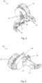
- Figs. 1 and 2 show perspective views of a reconfigurable GPR device 1 not being an embodiment of the invention from the rear and the front side, respectively.
- the reconfigurable GPR device 1 for acquiring radar data about a medium comprises a casing 4 surrounding a radar antenna 2 (indicated as dashed line) and a processor unit (not shown) connected to the antenna. Including the processor unit in the device 1 makes the device 1 autonomous, i.e. the GPR is not a "slave" to another external device, e.g. via cables.
- the antenna 2 is adapted to emit and receive radar waves of a first polarization (the antenna "has" a first polarization).
- the casing 4 comprises a top side 5, a bottom side 6 opposing the top side 5, and four side walls, namely a rear side wall 7, a front side wall 8 opposing the rear side wall 7, and two lateral side walls 9 and 9' opposite to each other.
- the casing 4 may alternatively comprise more or less than four side walls.
- the antenna 2 is located in the lower part of the casing 4, i.e. nearer to the bottom side 6 than to the top side 5, preferably in the lowermost quarter of the casing 4.
- the bottom side 6 corresponds to an emission side of the antenna 2, and the medium of interest is located adjacent (i.e. "below") the bottom side 6 when the device 1 is in operation, i.e. acquiring radar data about the medium.
- the casing 4 of the device 1 is made of a durable and/or rugged material, e.g. of a polycarbonate such as Lexan, such that the device is not damaged under harsh operating conditions in field usage. It is advantageous that the casing 4 is dust-protected and/or protected against splashing of water, e.g. according to IP 54 or better according to IEC standard 60529.
- the bottom side 6 of the casing 4 is made of a scratch-resistant and preferably slippery material.
- the bottom side 6 is easily interchangeable, e.g. by hand, meaning without using additional tools.
- the length, the width, and the height of the casing 4 are each smaller than 10 cm, and preferably smaller than 9 cm.
- the height of the casing 4, i.e. its dimension between the top side 5 and the bottom side 6, is preferably smaller than 8 cm, preferably smaller than 7 cm.
- Such dimensions make the device 1 ergonomic, and enable accessibility of tight spaces.
- the device is a handheld device, meaning that it may be operated when being held with the hands, preferably with one hand only. This allows the device 1 to be operated in areas which are difficult to access, e.g. corners of building structures, or between pipes suspended from a ceiling and the ceiling itself, or between pipes and other structural features.
- the small size and weight also allow the device 1 to be operated on vertical walls and in overhead situations.
- the casing 4 further comprises a connector 10, in particular a four-pin connector, on each side wall.
- a connector may be used for communication with an assembly such as a wheel assembly, see Figs. 3-6 .
- the connector 10 may be used for communication with a different assembly, e.g. comprising a camera, in particular a CCD camera, or an optical mouse, particularly for determining the movement of the device 1.
- the casing 4 comprises a second connector 11, e.g. a threaded hole, for mechanical connection of the assembly on each side wall, e.g. by a screw on the assembly.
- the casing 4 in Figs. 1 and 2 additionally comprises a cap 12, e.g. a rubber seal, covering at least one slot.
- the device 1 comprises a slot for a communication unit 13, e.g. a Wi-Fi 802. 11a/b/g/n device or a Bluetooth dongle, for communication with a remote processing unit.
- the device 1 may comprise a further slot, e.g. a USB-C connector 14.
- the further slot may be adapted for communication, e.g. for data transfer, and/or for receiving power from a remote power supply.
- the device 1 of Figs. 1 and 2 further comprises buttons 15 and 15' on the lateral side walls 9 and 9'.
- the buttons are functionally connected to the processor unit for controlling the device 1.
- the user may control at least one of the following actions by merely pressing one of the buttons 15 and 15': switch the device on, start the acquisition of radar data, mark a specific location (e.g. the location of a rebar) during the acquisition (e.g. by pressing the button twice during a short time interval, e.g. within 1 s), and switch the device off (e.g. by pressing the button for a long duration, e.g. for more than 1 s).
- a specific location e.g. the location of a rebar
- switch the device off e.g. by pressing the button for a long duration, e.g. for more than 1 s.
- buttons 15 and 15' allows for an ambidextral operation of the device, i.e. the device may be operated in a simple manner with the left hand and/or the right hand.
- the device 1 may alternatively only comprise one button.
- the operation of the device by pressing just one button (or one of two or more equivalent buttons) is simple and makes the acquisition of radar data with the device user-friendly.
- Figs. 3 and 4 show perspective views of the device 1 of Figs. 1 and 2 additionally comprising a wheel assembly 20.
- the device of Figs. 3 and 4 is a reconfigurable GPR device according to an embodiment of the invention.
- the wheel assembly 20 comprises a holder 21, a wheel 22 and a wheel rotation sensor 23 (indicated, but not visible on Figs.).
- the wheel rotation sensor 23 measures a quantity indicative of the rotation of the wheel 22 around its axis 24 (see Fig. 4 ).
- the wheel rotation sensor 23 may e.g. be a rotary encoder, and is connected to the processor unit (not shown in Figs. 3 and 4 ).
- the wheel rotation sensor 23 is adapted to sense a path length of the movement of the device.
- the wheel rotation sensor 23 is adapted to determine positional information from the path length, i.e. to determine coordinates of a position within a given frame of reference.
- the radar data may be linked to their respective position on the medium.
- the axis 24 (see Fig. 4 ) of the wheel 22 is pivotal relative to the casing 4, and hence to the first polarization.
- the wheel 22 has two stable orientations in respect of the casing 4, which differ by a pivoting angle ⁇ , which in particular is 90° as indicated by the bold arrow in Fig. 3 .
- the device exhibits at least two preferred directions of movement in respect of the first polarization.
- the device 1 may in particular be moved in the directions forward F (trailing wheel), backward B (leading wheel), left L and right R (both with the wheel in side-car configuration, not shown).
- the axis 22' of the wheel 22 is perpendicular to the side wall which the wheel assembly 20 is attached to; in trailing and leading wheel configurations, the axis 22' is parallel to that side wall.
- the polarization of the radar data acquired along a same path may be changed, e.g. from H- to V-polarization or vice versa, by pivoting the wheel from trailing/leading wheel to side-car configuration and measuring along the same path a second time. Radar data with different polarizations may in turn yield a better resolution and/or quality of data about the medium, in particular in specific depth ranges of the medium.
- the wheel assembly 20 may alternatively be attached to a different side wall of the device than the rear-side wall 7 (shown). Also, in this way, the polarization of the acquired radar data may be changed when measuring a second time along the same path.
- the wheel assembly 20 is removably attachable to the casing 4.
- the wheel assembly 20 may be attachable to several, in particular to at least four (as shown), of the side walls. It is advantageous that the wheel assembly 20 is attachable (and removable) to (and from) the casing 4 manually, i.e. by hand, without using additional tools.
- Such mode of attaching is simple and time-saving, and it may in particular be implemented by a snap-in. An embodiment of such snap-in mechanism is shown in Figs. 5 and 6 .
- Figs. 5 and 6 show perspective views of a wheel assembly 20.
- the holder 21 comprises four balls 24 which are mounted to the holder with a spring.
- the balls 24 fit into corresponding indentations 16 in the casing 4 (see Fig. 2 ) such that snapping the balls 24 into the indentations 16 leads to a mechanical connection between wheel assembly 20 and casing 4.
- such snap-in mechanism may be implemented via magnets on the holder 21 and on the casing 4.
- the holder 21 comprises a screw 25 which is adapted to interlock with the second connector 11 on the casing 4.
- the screw 25 may be used to fix the wheel assembly 20 on the casing 4.
- the screw 25 can be screwed into the casing 4 manually, i.e. without using further tools.
- the holder 21 further comprises a plug 26 adapted to set up an electrical connection between the wheel assembly 20 and components within the casing 4 when plugged into the connector 10.
- the wheel assembly 20 comprises a suspension 28 for the wheel 22.
- the suspension 28 is elastic, e.g. implemented by a spring, and adapted to press the wheel 22 against the surface of the medium while the device 1 is moved along the medium. This makes the path length and the positional information determined from measurements of the wheel rotation sensor 23 more accurate and reliable, e.g. in case of surface roughness.
- the device 1 may comprise a direction-determining unit.
- Fig. 7 shows a block diagram of a GPR device according to an example including such direction-determining unit 30.
- the direction-determining unit 30 is connected to the processor unit 3 and adapted to determine directional information.
- the directional information is descriptive of an angle between the direction of movement of the device and the first polarization.
- the wheel assembly 20 comprises an angle sensor 27 (indicated in Fig. 6 ) adapted to sense an angle between the axis 22' of the wheel and the holder 21.
- the angle sensor 27 is connected to the direction-determining unit 30 and may e.g. be a resistive or capacitive angle sensor.
- the direction-determining-unit 30 may be connected to a directional sensor 31 which is adapted to sense the direction of at least one of the movement and an acceleration of the device 1.
- the directional sensor 31 may comprise at least one of the following components: (i) It may comprise a camera 32, i.e. an optical encoder e.g. with a CCD camera, with a camera view directed at least partly towards the bottom side 6 of the casing 4.
- the direction-determining unit 30 is adapted to determine the directional information from subsequent images taken by the camera 32, e.g. by conventional image processing techniques, in order to retrieve the direction of movement and/or acceleration of the device 1.
- the surface of the medium exhibits a texture that facilitates the retrieval of the direction.
- the directional sensor 31 may comprise an accelerometer 33, e.g. a piezoelectric, piezoresistive or capacitive component. In that case, the direction-determining unit 30 is adapted to determine the direction of acceleration of the device.
- the directional sensor 31 may comprise a compass sensor 34, i.e. a sensor measuring a quantity indicative of the orientation of the sensor relative to a magnetic field direction in the surroundings, e.g. of the Earth's magnetic field.
- the directional sensor 31 may be implemented in an assembly which is attachable to the housing 4 similar to the wheel assembly 20, e.g. an assembly with a camera, or it may be implemented within the housing 4, e.g. an on-board accelerometer of the device.
- the processor unit is adapted to determine fused directional information from the directional information from different directional sensors.
- the (fused) directional information is indicative of the polarization of the acquired radar data, e.g. H- or V-polarization.
- the directional information is helpful for the processing and/or interpretation of the radar data in order to determine a high-quality image of the interior of the medium.
- the processing and/or interpretation may e.g. take into account the polarization of the acquired radar data and/or differ depending on said polarization.
- the directional information is stored and/or transmitted together with the radar data.
- the directional information is not only indicative of the polarization of the acquired radar data, but it may also be used to reconstruct the measurement path, i.e. the actual path along which the device is moved during acquiring the data.
- the directional information may comprise information about the orientation in which the device is used, e.g. on a floor, on a wall, on a slanted surface, or in an over-head setting. Such information may be evaluated by the user and/or the manufacturer, and it may support the user with measurement and interpretation information, and the further development of the device and/or acquisition methods.
- the processor unit 3 is adapted to control the antenna 2, and to receive the radar data from the antenna 2, as well as at least one of positional information from the wheel rotation sensor 23, if present, and directional information from the direction-determining unit 30, if present, see Fig. 7 .
- the radar data may be stored in an internal memory 40 of the device 1 or transmitted via a communication unit 13 together with at least one of the positional information and the directional information.
- the device preferably may further comprise a communication unit 13 adapted to transmit the radar data to a remote computing unit via a wireless connection, e.g. via Wi-Fi 802. 11a/b/g/n or Bluetooth.
- the remote computing unit may e.g. be a conventional computer or an iPad, preferably equipped with a software for processing the radar data and/or for determining an image of the interior structure of the medium from the radar data.
- the antenna 2 is a radar source with a frequency range between 50 MHz and 8000 MHz, in particular between 400 MHz and 6000 MHz.
- the processor unit 3 is configured to control the antenna 2 to emit a stepped-frequency continuous wave (SFCW).
- SFCW stepped-frequency continuous wave
- the device 1 does not need to comprise all units shown in the block diagram of Fig. 7 . While the antenna 2 and the processor unit 3 are essential parts, different examples comprise only one or both of the wheel rotation sensor 23 and the direction-determining unit 30.
- an autonomous GPR system for acquiring radar data comprises the device according to the invention as well as a power supply unit 50 adapted to supply power to the device 1. While power may be supplied to the device 1 via the slot 14, e.g. via a USB-C cable (see Fig. 1 ), it may be advantageous for certain applications to have the power supply unit 50 attached to the device 1.
- Figs. 8 and 9 show perspective views of an autonomous GPR system 60 not being an embodiment of the invention comprising a power supply unit 50 in form of a battery pack 51.
- the battery pack 51 is manually attachable to the casing 4, e.g. by a snap-in mechanism.
- the snap-in mechanism is implemented via magnets, e.g. three magnets.
- the battery pack 51 may comprise conventional batteries, e.g. rechargeable NiMH batteries. This has the advantage that such batteries are available in most places and that the system is easily transportable, even e.g. on airplanes.
- the battery pack 51 has a height of less than 2 cm measured from the top side 5 of the device 1.
- the autonomous system 60 is small in size and light-weight in order to be handy to operate in inaccessible areas, such as e.g. corners of building structures, underneath piping, or in over-head situations.
- the battery pack 51 may comprise a light pipe 52, wherein the colour or lighting pattern of one or more LEDs indicates an operating state of the device 1, such as e.g. "booting up”, “switched on”, “ready to acquire data” or "acquiring data”.
- the one or more LEDs may be located in the casing 4 or in the battery pack 51.
- Figs. 10 and 11 show perspective views of the system of Figs. 8 and 9 additionally comprising a wheel assembly 20 as e.g. shown in Figs. 5 and 6 .
- the system of Figs. 10 et 11 is an autonomous GPR system according to an embodiment of the invention.
- the autonomous GPR system 60 additionally comprises a rod 61 for holding the device 1, see Fig. 9 .
- the casing 4 of the device 1 comprises a connector, e.g. the second connectors 11 (see Fig. 1 ), and the system 60 further comprises a rod 61 with a joint 62 attachable, in particular manually attachable, to the connector.
- the rod 61 is screwable to three of the four second connectors 11, one on each side wall of the casing 4.
- the rod 61 is adapted to hold the device.
- the joint 62 comprises a ball joint 63, which facilitates that the device 1 follows the surface of the medium while being moved along the medium.
- the rod 61 comprises a telescopic rod, which is adjustable in length, e.g. up to 2 m of length.
- the GPR system 60 additionally comprises an inductive sensor 64 adapted to sense an electromagnetic field, see Fig. 11 .
- the inductive sensor 64 is adapted to determine a presence of a cable or a pipe from the sensed electromagnetic field.
- the inductive sensor 64 converts the strength of a magnetic or electrical field into a proportional value, which may be evaluated in terms of the presence of a cable or pipe.
- the inductive sensor 64 may operate passively, i.e. without transmitting an electromagnetic field.
- the inductive sensor 64 is adapted to sense an electric or magnetic field at a frequency between 45 Hz and 65 Hz, preferably around 55 Hz, in order to be able to detect cables with AC currents at 50 Hz or 60 Hz.
- the inductive sensor 64 may be adapted to transmit an electromagnetic field, which in particular induces electrical currents in the metallic objects, e.g. cables or pipes, in the vicinity. Such active transmission facilitates the location of objects which are not live wires, wherein a live wire is a wire with a load, i.e. carrying electric current.
- a signal generator is preferably used to generate an excitation of the object, in particular wherein a trace frequency of the excitation is between 400 Hz and 800 Hz or between 4 kHz and 150 kHz.
- the inductive sensor 64 is preferably attachable to the device 1 via a holder 65.
- the mechanism of the holder 65 may be similar to the one of the holder 21 of the wheel assembly, see above, i.e. preferably manually attachable, e.g. by snap-in. Additionally or alternatively, the inductive sensor 64 may be fixed on the device 1 with a screw screwable into the second connector 11. An electrical connection between the inductive sensor 64 and the device 1, in particular with the processor unit 3, is preferably set up via the connector 10.
- FIG. 12 shows a flow chart of such according to an embodiment of the invention.
- the method is for operating the device or the system according to the invention.
- the method comprises the following steps S1 to S5 and optionally additionally step S6:
- the method may comprise at least one of the following steps (dashed arrow lines indicate optional steps):
Landscapes
- Engineering & Computer Science (AREA)
- Remote Sensing (AREA)
- Physics & Mathematics (AREA)
- Radar, Positioning & Navigation (AREA)
- General Physics & Mathematics (AREA)
- Computer Networks & Wireless Communication (AREA)
- Life Sciences & Earth Sciences (AREA)
- Electromagnetism (AREA)
- Geophysics (AREA)
- General Life Sciences & Earth Sciences (AREA)
- Signal Processing (AREA)
- Environmental & Geological Engineering (AREA)
- Geology (AREA)
- Radar Systems Or Details Thereof (AREA)
- Control Of Position, Course, Altitude, Or Attitude Of Moving Bodies (AREA)
Description
- The present invention relates to a reconfigurable GPR device, an autonomous GPR system and a method for acquiring radar data about a medium.
- Ground penetrating radar (GPR) is commonly used for imaging a medium, i.e. generating images of the interior structure of the medium. In particular, such images contain information on the position and properties of layers, objects, cracks and/or voids in the medium. The underlying principle of GPR is the propagation of radar waves, e.g. with frequencies between 10 MHz and 10 GHz, which are emitted and received by at least one radar antenna. The propagation of radar waves is influenced by the structure and properties of the medium. In particular, radar waves are reflected at a boundary of materials with differing dielectric constant and/or diamagnetic constant. Hence GPR is commonly applied in non-destructive testing (NDT), e.g. on concrete, masonry, brickwork or wood. GPR is particularly useful for locating rebars or voids in building structures, such as houses and bridges.
- Radar waves are further characterized by their polarization. In particular, radar waves may exhibit different directions of polarization. Orthogonally polarized radar waves may exhibit H-polarization (horizontal) or V-polarization (vertical). It is well known that the penetration depth of radar waves as well as the resolution of the resulting image vary with the polarization of the radar waves and dependent on the interior structure of the medium. Rebars in a concrete wall may serve as an example: Radar waves that are polarized along the rebars may not penetrate to deeper parts of the medium behind the rebars, i.e. further away from the antenna than the rebars, while radar waves that are polarized in across-direction relative to the rebars may actually penetrate to deeper parts. For practical applications, it may hence be beneficial to choose the polarization depending on the structure and depth range of interest.
- Conventional GPR devices for NDT comprise handheld devices which can be operated on different surfaces, e.g. having different inclinations. Such handheld devices are e.g. known from
EP 2 720 065 A1EP 1 197 762 B1 . Changing the polarization of the emitted radio waves relative to the medium may be achieved by turning the device, e.g. by 90°, to switch between H-polarization and V-polarization. - Further, a prototype GPR platform for "Multi-Azimuth Ground Penetrating Radar Surveys to Improve the Imaging of Complex Fractures" is known from a journal article with the same title, published in Geosciences 2018, 8, 425, by Federico Lombardi and Maurizio Lualdi. The surveys were conducted by a GPR antenna mounted on a PVC sledge. Within the bottom of the antenna case and the sledge, a mechanical turntable for precise platform rotation was inserted.
- However, such conventional GPR devices have several disadvantages. Firstly, they are quite big, heavy and bulky for a convenient operation by hand. Secondly, it is difficult - and often impossible - to acquire data in corners and around edges of a building structure. Thirdly, it is impossible to change the polarization for acquiring data on the same path with both H- and V-polarization. Fourthly, a refined processing and interpretation of the acquired radar data is impossible since information regarding the polarization is not regularly available in the data set.
- The problem to be solved by the present invention is therefore to provide a reconfigurable GPR device which allows acquiring radar data of different polarization along a defined path on a medium.
- This problem is solved by a reconfigurable GPR device for acquiring radar data about a medium according to
claim 1. GPR means ground penetrating radar and includes the use of radar waves for imaging an interior structure of a medium, such as e.g. soil, rock, ice, concrete, wood or other building material. GPR for concrete structures is preferably operated within a frequency range between 50 MHz and 8000 MHz, in particular between 400 MHz and 6000 MHz. Preferably, the device acquires and processes the radar data in real-time, i.e. the time frame is on the order of milliseconds, in particular smaller than 1 s. - The device comprises a radar antenna with a first polarization, a processor unit, in particular an FPGA or a CPU, connected to said antenna and a casing around the antenna and the processor unit. The antenna is preferably adapted to emit and receive radar waves which travel through the medium, and to convert the received radar waves into radar data. Radar data are preferably a representation of the radar waves as an electric signal. The term "radar antenna with a first polarization" is used in the sense that the radar waves emitted by the antenna exhibit the first polarization. It shall explicitly include an antenna adapted to emit radar waves of different polarizations. The casing preferably protects the antenna and the processor unit, e.g. against at least one of dust and liquids. However, the casing does not necessarily have to be closed on all sides.
- Furthermore, the device comprises a wheel assembly. The device may also comprise a direction-determining unit; such embodiment is, however, presently not claimed.
- The wheel assembly comprises a holder, a wheel and a wheel rotation sensor. The wheel rotation sensor is connected to the processor unit. An axis of the wheel is pivotal relative to the first polarization. I.e. a rolling direction of the wheel, and hence of the device, may be changed by pivoting the wheel. This allows acquiring radar data with different polarizations along the same path, which may in turn improve the quality and resolution of the resulting image of the interior structure of the medium.
- The wheel rotation sensor is adapted to sense a path length of the movement of the device, and in particular to determine positional information from the path length. The wheel rotation sensor may e.g. be a rotary encoder. The path length, and preferably positional information, is advantageously used in the display and/or interpretation of the radar data, e.g. for locating an object within the medium, e.g. a rebar or a void in concrete or a building structure.
- If present (but presently not claimed), the direction-determining unit is connected to the processor unit and adapted to determine directional information. The directional information is descriptive of an angle between the direction of movement of the device and the first polarization. Such directional information may support the processing and/or the interpretation of the radar data. In particular, directional information is taken into account for processing and/or interpreting radar data with different polarizations acquired along the same path. Hence it is advantageous that the processor unit is adapted to generate a data set comprising the radar data and at least one of the positional information and the directional information.
- The direction-determining unit may be adapted to determine directional information in different ways. In an embodiment, the wheel assembly comprises an angle sensor adapted to sense an angle between the axis of the wheel and the holder. In particular, the angle sensor is connected to the direction-determining unit. In another embodiment, the direction-determining unit is connected to a different directional sensor, e.g. an optical encoder, adapted to sense the direction of at least one of the movement and an acceleration of the device. Furthermore, the processor unit may be adapted to determine fused directional information from the directional information from different directional sensors. In the following, the term "directional sensor" is understood as including "orientational sensors" such as a compass sensor or an accelerometer.
- As described above, the device exhibits at least two preferred directions of movement in respect to the first polarization, such that the antenna is orientable in two distinct orientations relative to the direction of movement of the device. This allows to adjust the polarization of the radar waves for optimizing the quality and/or resolution of the resulting image, e.g. dependent on the interior structure of the medium.
- Further, the wheel (i.e. its axis) exhibits two stable orientations, in respect to the casing, differing by a pivoting angle, which may e.g. be 90°, in particular to enable emitting waves with H- and V-polarization. Preferably, other orientations of the wheel different from the two stable orientations are unstable. In particular, a stable orientation requires applying a torque or a force above a given threshold in order to change the orientation. Such stable orientation is achieved by means of a snap-in mechanism, implemented by an elastic force, such as from a spring, or of a magnetic force, which needs to be overcome to change the orientation.
- The device is a handheld device.
- In an advantageous embodiment, the wheel assembly is removably attachable to the casing, i.e. it can be non-destructively attached to and removed from the casing. In particular, the wheel assembly may be attachable to several side walls of the casing. This allows to change the polarization relative to the movement of the device by attaching the wheel assembly to a different side wall. Preferably the wheel assembly is attachable manually, in particular by snap-in. "Manually" means that attaching and/or detaching may be done with bare hands, i.e. without using any tools, such as a screw-driver. "Snap-in" describes a fastener, wherein the attached wheel assembly can only be detached if a detaching force is larger than a certain threshold. Such snap-in may e.g. be achieved by means of an elastic force, e.g. via a spring, or of a magnetic force.
- In another embodiment, the device comprises a communication unit adapted to transmit the radar data to a remote computing unit via a wireless connection, in particular wherein the wireless connection comprises Wi-Fi or Bluetooth. Preferably the communication unit is one of located in the casing or part of the device.
- A further aspect of the invention relates to an autonomous GPR system for acquiring radar data according to
claim 13. The system comprises the device described above and a power supply unit electrically connected to the device and adapted to supply power to the device. In particular, the power supply unit may be attachable to the device, preferably manually attachable. The power supply unit may comprise at least one battery, e.g. at least one rechargeable battery. Such system is autonomous in the sense that it may be operated autonomously, i.e. without cables attached. The system may be connected to a separate electronics apparatus, e.g. a remote computing unit and/or a unit with a display. This facilitates a simple use as well as its application to areas which are not easily accessible, such as corners in building structures. - Yet another aspect of the invention relates to a method for acquiring radar data about a medium, for operating the device or the system described above, according to
claim 16. - The method comprises the steps of moving the GPR device comprising the radar antenna along the medium, repetitively emitting radar waves of the first polarization into the medium by means of the antenna, repetitively receiving radar waves by means of the antenna, and converting the received radar waves to radar data. Furthermore, it comprises the step of changing an angle between a direction of movement of the device and the first polarization and repeating the above steps. Presently not part of the invention is a further step of determining directional information descriptive of an angle between a direction of movement of the device and the first polarization.
- Other advantageous embodiments are listed in the dependent claims as well as in the description below.
- The invention will be better understood and objects other than those set forth above will become apparent from the following detailed description thereof. Such description refers to the annexed drawings, wherein:
-
Figs. 1 and 2 show perspective views of a reconfigurable GPR device not being an embodiment of the invention from the rear and the front side, respectively; -
Figs. 3 and 4 show perspective views of the device ofFigs. 1 and 2 additionally comprising a wheel assembly. The device ofFigs. 3 and 4 is a reconfigurable GPR device according to an embodiment of the invention; -
Figs. 5 and 6 show perspective views of a wheel assembly; -
Fig. 7 shows a block diagram of a GPR device or GPR system not being part of the invention; -
Figs. 8 and 9 show perspective views of an autonomous GPR system not being an embodiment of the invention comprising a power supply unit; -
Figs. 10 and 11 show perspective views of the system ofFigs. 8 and 9 additionally comprising a wheel assembly. The system ofFigs. 10 and 11 is an autonomous GPR system according to an embodiment of the invention; -
Fig. 12 shows a flow chart of a method for acquiring radar data -
Figs. 1 and 2 show perspective views of areconfigurable GPR device 1 not being an embodiment of the invention from the rear and the front side, respectively. Thereconfigurable GPR device 1 for acquiring radar data about a medium comprises acasing 4 surrounding a radar antenna 2 (indicated as dashed line) and a processor unit (not shown) connected to the antenna. Including the processor unit in thedevice 1 makes thedevice 1 autonomous, i.e. the GPR is not a "slave" to another external device, e.g. via cables. Theantenna 2 is adapted to emit and receive radar waves of a first polarization (the antenna "has" a first polarization). Thecasing 4 comprises a top side 5, abottom side 6 opposing the top side 5, and four side walls, namely arear side wall 7, afront side wall 8 opposing therear side wall 7, and twolateral side walls 9 and 9' opposite to each other. In general, thecasing 4 may alternatively comprise more or less than four side walls. Theantenna 2 is located in the lower part of thecasing 4, i.e. nearer to thebottom side 6 than to the top side 5, preferably in the lowermost quarter of thecasing 4. In general, thebottom side 6 corresponds to an emission side of theantenna 2, and the medium of interest is located adjacent (i.e. "below") thebottom side 6 when thedevice 1 is in operation, i.e. acquiring radar data about the medium. - Preferably, the
casing 4 of thedevice 1 is made of a durable and/or rugged material, e.g. of a polycarbonate such as Lexan, such that the device is not damaged under harsh operating conditions in field usage. It is advantageous that thecasing 4 is dust-protected and/or protected against splashing of water, e.g. according to IP 54 or better according to IEC standard 60529. In particular, thebottom side 6 of thecasing 4 is made of a scratch-resistant and preferably slippery material. Preferably, thebottom side 6 is easily interchangeable, e.g. by hand, meaning without using additional tools. - In an example the length, the width, and the height of the
casing 4 are each smaller than 10 cm, and preferably smaller than 9 cm. The height of thecasing 4, i.e. its dimension between the top side 5 and thebottom side 6, is preferably smaller than 8 cm, preferably smaller than 7 cm. Such dimensions make thedevice 1 ergonomic, and enable accessibility of tight spaces. The device is a handheld device, meaning that it may be operated when being held with the hands, preferably with one hand only. This allows thedevice 1 to be operated in areas which are difficult to access, e.g. corners of building structures, or between pipes suspended from a ceiling and the ceiling itself, or between pipes and other structural features. The small size and weight also allow thedevice 1 to be operated on vertical walls and in overhead situations. - In the the device of
Figs. 1 and 2 , thecasing 4 further comprises aconnector 10, in particular a four-pin connector, on each side wall. Such connector may be used for communication with an assembly such as a wheel assembly, seeFigs. 3-6 . Alternatively, theconnector 10 may be used for communication with a different assembly, e.g. comprising a camera, in particular a CCD camera, or an optical mouse, particularly for determining the movement of thedevice 1. Further thecasing 4 comprises asecond connector 11, e.g. a threaded hole, for mechanical connection of the assembly on each side wall, e.g. by a screw on the assembly. - The
casing 4 inFigs. 1 and 2 additionally comprises acap 12, e.g. a rubber seal, covering at least one slot. In particular, thedevice 1 comprises a slot for acommunication unit 13, e.g. a Wi-Fi 802. 11a/b/g/n device or a Bluetooth dongle, for communication with a remote processing unit. Also, thedevice 1 may comprise a further slot, e.g. a USB-C connector 14. The further slot may be adapted for communication, e.g. for data transfer, and/or for receiving power from a remote power supply. - The
device 1 ofFigs. 1 and 2 further comprisesbuttons 15 and 15' on thelateral side walls 9 and 9'. The buttons are functionally connected to the processor unit for controlling thedevice 1. In particular, the user may control at least one of the following actions by merely pressing one of thebuttons 15 and 15': switch the device on, start the acquisition of radar data, mark a specific location (e.g. the location of a rebar) during the acquisition (e.g. by pressing the button twice during a short time interval, e.g. within 1 s), and switch the device off (e.g. by pressing the button for a long duration, e.g. for more than 1 s). The presence of at least twobuttons 15 and 15' allows for an ambidextral operation of the device, i.e. the device may be operated in a simple manner with the left hand and/or the right hand. In general, thedevice 1 may alternatively only comprise one button. The operation of the device by pressing just one button (or one of two or more equivalent buttons) is simple and makes the acquisition of radar data with the device user-friendly. -
Figs. 3 and 4 show perspective views of thedevice 1 ofFigs. 1 and 2 additionally comprising awheel assembly 20. The device ofFigs. 3 and 4 is a reconfigurable GPR device according to an embodiment of the invention. Thewheel assembly 20 comprises aholder 21, awheel 22 and a wheel rotation sensor 23 (indicated, but not visible on Figs.). Thewheel rotation sensor 23 measures a quantity indicative of the rotation of thewheel 22 around its axis 24 (seeFig. 4 ). Thewheel rotation sensor 23 may e.g. be a rotary encoder, and is connected to the processor unit (not shown inFigs. 3 and 4 ). Thewheel rotation sensor 23 is adapted to sense a path length of the movement of the device. In particular, thewheel rotation sensor 23 is adapted to determine positional information from the path length, i.e. to determine coordinates of a position within a given frame of reference. Thus, the radar data may be linked to their respective position on the medium. - Further, the axis 24 (see
Fig. 4 ) of thewheel 22 is pivotal relative to thecasing 4, and hence to the first polarization. Thewheel 22 has two stable orientations in respect of thecasing 4, which differ by a pivoting angle α, which in particular is 90° as indicated by the bold arrow inFig. 3 . Thus, the device exhibits at least two preferred directions of movement in respect of the first polarization. As indicated by the bold arrows inFig. 4 , thedevice 1 may in particular be moved in the directions forward F (trailing wheel), backward B (leading wheel), left L and right R (both with the wheel in side-car configuration, not shown). Note: In side-car configuration, the axis 22' of thewheel 22 is perpendicular to the side wall which thewheel assembly 20 is attached to; in trailing and leading wheel configurations, the axis 22' is parallel to that side wall. Thus, the polarization of the radar data acquired along a same path may be changed, e.g. from H- to V-polarization or vice versa, by pivoting the wheel from trailing/leading wheel to side-car configuration and measuring along the same path a second time. Radar data with different polarizations may in turn yield a better resolution and/or quality of data about the medium, in particular in specific depth ranges of the medium. - As is understood from
Figs. 3 and 4 , thewheel assembly 20 may alternatively be attached to a different side wall of the device than the rear-side wall 7 (shown). Also, in this way, the polarization of the acquired radar data may be changed when measuring a second time along the same path. Preferably, thewheel assembly 20 is removably attachable to thecasing 4. In general, thewheel assembly 20 may be attachable to several, in particular to at least four (as shown), of the side walls. It is advantageous that thewheel assembly 20 is attachable (and removable) to (and from) thecasing 4 manually, i.e. by hand, without using additional tools. Such mode of attaching is simple and time-saving, and it may in particular be implemented by a snap-in. An embodiment of such snap-in mechanism is shown inFigs. 5 and 6 . -
Figs. 5 and 6 show perspective views of awheel assembly 20. Theholder 21 comprises fourballs 24 which are mounted to the holder with a spring. Theballs 24 fit into correspondingindentations 16 in the casing 4 (seeFig. 2 ) such that snapping theballs 24 into theindentations 16 leads to a mechanical connection betweenwheel assembly 20 andcasing 4. Alternatively, such snap-in mechanism may be implemented via magnets on theholder 21 and on thecasing 4. Further, theholder 21 comprises ascrew 25 which is adapted to interlock with thesecond connector 11 on thecasing 4. Thus, thescrew 25 may be used to fix thewheel assembly 20 on thecasing 4. Advantageously, thescrew 25 can be screwed into thecasing 4 manually, i.e. without using further tools. Theholder 21 further comprises aplug 26 adapted to set up an electrical connection between thewheel assembly 20 and components within thecasing 4 when plugged into theconnector 10. - Preferably, the
wheel assembly 20 comprises asuspension 28 for thewheel 22. Thesuspension 28 is elastic, e.g. implemented by a spring, and adapted to press thewheel 22 against the surface of the medium while thedevice 1 is moved along the medium. This makes the path length and the positional information determined from measurements of thewheel rotation sensor 23 more accurate and reliable, e.g. in case of surface roughness. - In an example not being part of the invention, the
device 1 may comprise a direction-determining unit.Fig. 7 shows a block diagram of a GPR device according to an example including such direction-determiningunit 30. The direction-determiningunit 30 is connected to theprocessor unit 3 and adapted to determine directional information. The directional information is descriptive of an angle between the direction of movement of the device and the first polarization. In that case, it is advantageous that thewheel assembly 20 comprises an angle sensor 27 (indicated inFig. 6 ) adapted to sense an angle between the axis 22' of the wheel and theholder 21. Theangle sensor 27 is connected to the direction-determiningunit 30 and may e.g. be a resistive or capacitive angle sensor. - As an alternative or in addition to the
angle sensor 27 in thewheel assembly 20, the direction-determining-unit 30 may be connected to adirectional sensor 31 which is adapted to sense the direction of at least one of the movement and an acceleration of thedevice 1. Thedirectional sensor 31 may comprise at least one of the following components: (i) It may comprise acamera 32, i.e. an optical encoder e.g. with a CCD camera, with a camera view directed at least partly towards thebottom side 6 of thecasing 4. In that case, the direction-determiningunit 30 is adapted to determine the directional information from subsequent images taken by thecamera 32, e.g. by conventional image processing techniques, in order to retrieve the direction of movement and/or acceleration of thedevice 1. Advantageously, the surface of the medium exhibits a texture that facilitates the retrieval of the direction. (ii) Thedirectional sensor 31 may comprise anaccelerometer 33, e.g. a piezoelectric, piezoresistive or capacitive component. In that case, the direction-determiningunit 30 is adapted to determine the direction of acceleration of the device. (iii) Thedirectional sensor 31 may comprise acompass sensor 34, i.e. a sensor measuring a quantity indicative of the orientation of the sensor relative to a magnetic field direction in the surroundings, e.g. of the Earth's magnetic field. In general, thedirectional sensor 31 may be implemented in an assembly which is attachable to thehousing 4 similar to thewheel assembly 20, e.g. an assembly with a camera, or it may be implemented within thehousing 4, e.g. an on-board accelerometer of the device. - If more than one directional information is present, preferably the processor unit is adapted to determine fused directional information from the directional information from different directional sensors. The (fused) directional information is indicative of the polarization of the acquired radar data, e.g. H- or V-polarization. The directional information is helpful for the processing and/or interpretation of the radar data in order to determine a high-quality image of the interior of the medium. The processing and/or interpretation may e.g. take into account the polarization of the acquired radar data and/or differ depending on said polarization. Thus, it is preferred that the directional information is stored and/or transmitted together with the radar data.
- In general, the directional information is not only indicative of the polarization of the acquired radar data, but it may also be used to reconstruct the measurement path, i.e. the actual path along which the device is moved during acquiring the data. Also, the directional information may comprise information about the orientation in which the device is used, e.g. on a floor, on a wall, on a slanted surface, or in an over-head setting. Such information may be evaluated by the user and/or the manufacturer, and it may support the user with measurement and interpretation information, and the further development of the device and/or acquisition methods.
- Further, the
processor unit 3 is adapted to control theantenna 2, and to receive the radar data from theantenna 2, as well as at least one of positional information from thewheel rotation sensor 23, if present, and directional information from the direction-determiningunit 30, if present, seeFig. 7 . The radar data may be stored in aninternal memory 40 of thedevice 1 or transmitted via acommunication unit 13 together with at least one of the positional information and the directional information. For that purpose, the device preferably may further comprise acommunication unit 13 adapted to transmit the radar data to a remote computing unit via a wireless connection, e.g. via Wi-Fi 802. 11a/b/g/n or Bluetooth. The remote computing unit may e.g. be a conventional computer or an iPad, preferably equipped with a software for processing the radar data and/or for determining an image of the interior structure of the medium from the radar data. - Preferably, the
antenna 2 is a radar source with a frequency range between 50 MHz and 8000 MHz, in particular between 400 MHz and 6000 MHz. In particular, theprocessor unit 3 is configured to control theantenna 2 to emit a stepped-frequency continuous wave (SFCW). - In this example not being part of the invention, the
device 1 does not need to comprise all units shown in the block diagram ofFig. 7 . While theantenna 2 and theprocessor unit 3 are essential parts, different examples comprise only one or both of thewheel rotation sensor 23 and the direction-determiningunit 30. - According to a further aspect of the invention, an autonomous GPR system for acquiring radar data comprises the device according to the invention as well as a
power supply unit 50 adapted to supply power to thedevice 1. While power may be supplied to thedevice 1 via theslot 14, e.g. via a USB-C cable (seeFig. 1 ), it may be advantageous for certain applications to have thepower supply unit 50 attached to thedevice 1. -
Figs. 8 and 9 show perspective views of anautonomous GPR system 60 not being an embodiment of the invention comprising apower supply unit 50 in form of abattery pack 51. Preferably, thebattery pack 51 is manually attachable to thecasing 4, e.g. by a snap-in mechanism. In a particular example, the snap-in mechanism is implemented via magnets, e.g. three magnets. Thebattery pack 51 may comprise conventional batteries, e.g. rechargeable NiMH batteries. This has the advantage that such batteries are available in most places and that the system is easily transportable, even e.g. on airplanes. Advantageously, thebattery pack 51 has a height of less than 2 cm measured from the top side 5 of thedevice 1. Thus, theautonomous system 60 is small in size and light-weight in order to be handy to operate in inaccessible areas, such as e.g. corners of building structures, underneath piping, or in over-head situations. Further, thebattery pack 51 may comprise alight pipe 52, wherein the colour or lighting pattern of one or more LEDs indicates an operating state of thedevice 1, such as e.g. "booting up", "switched on", "ready to acquire data" or "acquiring data". The one or more LEDs may be located in thecasing 4 or in thebattery pack 51.Figs. 10 and 11 show perspective views of the system ofFigs. 8 and 9 additionally comprising awheel assembly 20 as e.g. shown inFigs. 5 and 6 . The system ofFigs. 10 et 11 is an autonomous GPR system according to an embodiment of the invention. - Advantageously, the
autonomous GPR system 60 additionally comprises arod 61 for holding thedevice 1, seeFig. 9 . This allows simpler operation in inaccessible areas. In an embodiment, thecasing 4 of thedevice 1 comprises a connector, e.g. the second connectors 11 (seeFig. 1 ), and thesystem 60 further comprises arod 61 with a joint 62 attachable, in particular manually attachable, to the connector. In an embodiment, therod 61 is screwable to three of the foursecond connectors 11, one on each side wall of thecasing 4. Therod 61 is adapted to hold the device. Preferably the joint 62 comprises a ball joint 63, which facilitates that thedevice 1 follows the surface of the medium while being moved along the medium. Also, it is advantageous that therod 61 comprises a telescopic rod, which is adjustable in length, e.g. up to 2 m of length. - In an embodiment, the
GPR system 60 additionally comprises aninductive sensor 64 adapted to sense an electromagnetic field, seeFig. 11 . In particular, theinductive sensor 64 is adapted to determine a presence of a cable or a pipe from the sensed electromagnetic field. Preferably, theinductive sensor 64 converts the strength of a magnetic or electrical field into a proportional value, which may be evaluated in terms of the presence of a cable or pipe. For that purpose, theinductive sensor 64 may operate passively, i.e. without transmitting an electromagnetic field. In particular, theinductive sensor 64 is adapted to sense an electric or magnetic field at a frequency between 45 Hz and 65 Hz, preferably around 55 Hz, in order to be able to detect cables with AC currents at 50 Hz or 60 Hz. In a different embodiment, theinductive sensor 64 may be adapted to transmit an electromagnetic field, which in particular induces electrical currents in the metallic objects, e.g. cables or pipes, in the vicinity. Such active transmission facilitates the location of objects which are not live wires, wherein a live wire is a wire with a load, i.e. carrying electric current. In that case, a signal generator is preferably used to generate an excitation of the object, in particular wherein a trace frequency of the excitation is between 400 Hz and 800 Hz or between 4 kHz and 150 kHz. In general, theinductive sensor 64 is preferably attachable to thedevice 1 via aholder 65. The mechanism of theholder 65 may be similar to the one of theholder 21 of the wheel assembly, see above, i.e. preferably manually attachable, e.g. by snap-in. Additionally or alternatively, theinductive sensor 64 may be fixed on thedevice 1 with a screw screwable into thesecond connector 11. An electrical connection between theinductive sensor 64 and thedevice 1, in particular with theprocessor unit 3, is preferably set up via theconnector 10. - Yet another aspect of the invention relates to a method for acquiring radar data about a medium.
Fig. 12 shows a flow chart of such according to an embodiment of the invention. The method is for operating the device or the system according to the invention. The method comprises the following steps S1 to S5 and optionally additionally step S6: - Step S1: Moving the GPR device comprising the radar antenna along the medium. In most cases, "moving along the medium" is to be understood as moving / pushing / dragging along a measurement path on the surface of the medium, in particular wherein the bottom side of the casing is in contact with the surface. In special applications, however, the casing of the device may not be in direct contact with the surface. In an embodiment, the device or the system is mounted to a vehicle following the measurement path, e.g. a drone, which facilitates acquiring radar data over a large or otherwise inaccessible area.
- Step S2: Repetitively emitting radar waves of a first polarization into the medium by means of the antenna. The radar waves may be emitted as radar pulses, a continuous wave or stepped-frequency continuous wave. The first polarization is defined by the antenna and the control of the antenna through the processor unit.
- Step S3: Repetitively receiving radar waves by means of the antenna. The radar waves reflected by the medium, e.g. by boundaries between regions of different relative dielectric permittivity in the medium, are received by the same antenna that emits the radar waves. However, it is also feasible in examples not according to the invention to separate an emitting antenna from a receiving antenna. Steps S2 and S3 are repeated multiple times when acquiring radar measurements.
- Step S4: Converting the received radar waves to radar data, in particular wherein radar data are a representation of the radar waves as an electric signal. Step S4 may comprise converting analog data to digital data in preparation for data storage, transmission or processing.
- Step S5: Changing an angle between a direction of movement of the device and the first polarization, and repeating the
above steps S 1 to S4. By changing said angle, the polarization of the radar data is changed, e.g. from H- to V-polarization or vice versa. Acquiring differently polarized radar data may yield higher-quality images of the interior of the medium. In particular, differently polarized radar waves may penetrate into the medium up to different depth, i.e. distance from the antenna, depending on the reflection and/or absorption properties of the medium. Hence radar data with different polarizations may exhibit a high resolution in different depth ranges. Preferably, changing the angle between the direction of movement of the device and the first polarization comprises pivoting an axis of a wheel relative to the first polarization, in particular by a pivoting angle, and turning the casing by the pivoting angle. In general, e.g. if no wheel is present and thus according to an example not being part of the invention, the device may be turned by the pivoting angle, and then moved along the measurement path. - Step S6 (presently not part of the invention): Determining directional information descriptive of an angle between the direction of movement of the device and the first polarization. Such directional information characterizes the polarization of the acquired radar data, e.g. H- or V-polarization. Hence it is an important parameter and it may support the processing and/or interpretation of the radar data. Step S6 may comprise the sub-step of sensing the angle between the direction of the movement and the first polarization by means of a directional sensor. The directional information may be determined from measurements of different sensors, e.g. an angle sensor, a camera, an accelerometer or a compass sensor as described above. Step S6 may be performed additionally to step S5.
- Optionally, the method may comprise at least one of the following steps (dashed arrow lines indicate optional steps):
- Step S7: Generating a data set comprising the radar data and the directional information. Such data set may then be stored in an internal memory of the device or transmitted to a remote computing unit as described above.
- Step S8: Processing the radar data taking into account the directional information, and in particular generating an image of a structure, i.e. an interior structure, of the medium from the radar data taking into account the directional information. As described above, such processing may lead to a higher-quality image of the structure than conventional processing methods, in particular in the case of anisotropic reflection and/or absorption properties of the medium.
Claims (17)
- A reconfigurable ground penetrating radar, GPR, device (1) for acquiring radar data about a medium, comprising- a radar antenna (2) with a first polarization,- a processor unit (3) connected to said antenna (2),- a casing (4) around the antenna (2) and the processor unit (3),- a wheel assembly (20) comprising a holder (21), a wheel (22) and a wheel rotation sensor (23), wherein the wheel rotation sensor (23) is connected to the processor unit (3), wherein an axis (22') of the wheel (22) is pivotal relative to the first polarization,characterized in thatwherein the wheel rotation sensor (23) is adapted to sense a path length of the movement of the device (1),wherein the device (1) exhibits two preferred directions of movement in respect of the first polarization,wherein the axis (22') of the wheel (22) exhibits two stable orientations, in respect to the casing (4), differing by a pivoting angle (α),wherein the stable orientations are achieved by means of a snap-in mechanism, implemented by an elastic force, or of a magnetic force, andwherein the device (1) is a handheld device.
- The device of claim 1,
wherein the antenna (2) is adapted to emit and receive radar waves which travel through the medium, and to convert the received radar waves into radar data. - The device of any of the preceding claims,
wherein the wheel rotation sensor (23) is adapted to determine positional information from the path length. - The device of any of the preceding claims,wherein the processor unit (3) is adapted to control the antenna (2), and to receive the radar data as well as positional information from the wheel rotation sensor (23),in particular wherein the processor unit (3) is adapted to generate a data set comprising the radar data and the positional information.
- The device of any of the preceding claims,
wherein other orientations of the axis (22') of the wheel (22) different from the two stable orientations are unstable. - The device of any of the preceding claims,
wherein the pivoting angle (α) is 90°. - The device of any of the preceding claims,wherein the wheel assembly (20) is removably attachable to the casing (4),in particular wherein the wheel assembly (20) is attachable manually, in particular by snap-in.
- The device of any of the preceding claims,wherein the casing (4) comprises side walls, in particular four side walls (7, 8, 9, 9'),wherein the wheel assembly (20) is attachable to several, in particular to at least four, of the side walls,wherein the wheel assembly (20) is attachable manually, in particular by snap-in.
- The device of any of the preceding claims,
wherein the antenna (2) is a radar source with a frequency range between 50 MHz and 8000 MHz, in particular between 400 MHz and 6000 MHz. - The device of any of the preceding claims,
wherein the processor unit (3) is configured to control the antenna (2) to emit a stepped-frequency continuous wave. - The device of any of the preceding claims,
wherein a length, a width, and a height of the casing (4) are each smaller than 10 cm. - The device of any of the preceding claims, further comprising- a communication unit (13) adapted to transmit the radar data to a remote computing unit via a wireless connection, in particular wherein the wireless connection comprises Wi-Fi or Bluetooth,
in particular wherein the communication unit (13) is located in the casing (4). - An autonomous GPR system (60) for acquiring radar data, comprising- the device (1) of any of the preceding claims,- a power supply unit (50) electrically connected to the device (1) and adapted to supply power to the device (1),wherein the system is autonomous in the sense that it is operable without cables attached,in particular wherein the power supply unit (50) is attachable to the device (1), in particular manually attachable.
- The system of claim 13,wherein the casing (4) of the device (1) comprises a connector (11), further comprising- a rod (61) with a joint (62) attachable to, in particular manually attachable to, the connector (11), wherein the rod (61) is adapted to hold the device (1),in particular wherein the joint (62) comprises a ball joint (63), and in particular wherein the rod (61) comprises a telescopic rod.
- The system of any of claims 13 to 14, further comprising- an inductive sensor (64) adapted to sense an electromagnetic field, in particular adapted to determine a presence of a cable or a pipe from the sensed electromagnetic field.
- A method for acquiring radar data about a medium, for operating the GPR device (1) of any of the claims 1 to 12 or the system (60) of any of the claims 13 to 15, comprising the steps of- moving the GPR device (1) comprising the radar antenna (2) along the medium,- repetitively emitting radar waves of the first polarization into the medium by means of the antenna (2),- repetitively receiving radar waves by means of the antenna (2),- converting the received radar waves to radar data,- changing an angle between a direction of movement of the device (1) and the first polarization, and repeating the above steps.
- The method of claim 16,
wherein changing the angle between the direction of movement of the device (1) and the first polarization comprises pivoting the axis (22') of the wheel (22) relative to the first polarization.
Priority Applications (2)
| Application Number | Priority Date | Filing Date | Title |
|---|---|---|---|
| EP23186203.8A EP4249962A3 (en) | 2019-08-13 | 2019-08-13 | Reconfigurable gpr device |
| PL19755334.0T PL3994489T3 (en) | 2019-08-13 | 2019-08-13 | RECONFIGURABLE GPR GPR DEVICE |
Applications Claiming Priority (1)
| Application Number | Priority Date | Filing Date | Title |
|---|---|---|---|
| PCT/EP2019/071688 WO2020253975A1 (en) | 2019-08-13 | 2019-08-13 | Reconfigurable gpr device |
Related Child Applications (1)
| Application Number | Title | Priority Date | Filing Date |
|---|---|---|---|
| EP23186203.8A Division EP4249962A3 (en) | 2019-08-13 | 2019-08-13 | Reconfigurable gpr device |
Publications (2)
| Publication Number | Publication Date |
|---|---|
| EP3994489A1 EP3994489A1 (en) | 2022-05-11 |
| EP3994489B1 true EP3994489B1 (en) | 2023-07-26 |
Family
ID=67660087
Family Applications (2)
| Application Number | Title | Priority Date | Filing Date |
|---|---|---|---|
| EP23186203.8A Pending EP4249962A3 (en) | 2019-08-13 | 2019-08-13 | Reconfigurable gpr device |
| EP19755334.0A Active EP3994489B1 (en) | 2019-08-13 | 2019-08-13 | Reconfigurable gpr device |
Family Applications Before (1)
| Application Number | Title | Priority Date | Filing Date |
|---|---|---|---|
| EP23186203.8A Pending EP4249962A3 (en) | 2019-08-13 | 2019-08-13 | Reconfigurable gpr device |
Country Status (9)
| Country | Link |
|---|---|
| US (2) | US11914029B2 (en) |
| EP (2) | EP4249962A3 (en) |
| JP (1) | JP7406621B2 (en) |
| KR (1) | KR102727488B1 (en) |
| CN (1) | CN114303072B (en) |
| AU (1) | AU2019452391B2 (en) |
| ES (1) | ES2958913T3 (en) |
| PL (1) | PL3994489T3 (en) |
| WO (1) | WO2020253975A1 (en) |
Families Citing this family (5)
| Publication number | Priority date | Publication date | Assignee | Title |
|---|---|---|---|---|
| US11770377B1 (en) * | 2020-06-29 | 2023-09-26 | Cyral Inc. | Non-in line data monitoring and security services |
| JP2024060115A (en) * | 2021-04-26 | 2024-05-02 | 株式会社計測技術サービス | Information processing device |
| CN115201814A (en) * | 2022-06-30 | 2022-10-18 | 中国电波传播研究所(中国电子科技集团公司第二十二研究所) | Building structure radar detection device and method based on image positioning |
| USD1097836S1 (en) * | 2022-08-17 | 2025-10-14 | Proceq Ag | Sensor for detecting metal |
| CN120386000A (en) * | 2025-06-27 | 2025-07-29 | 南京大学 | UAV-borne microwave phase difference underground pipeline detection device and method |
Family Cites Families (9)
| Publication number | Priority date | Publication date | Assignee | Title |
|---|---|---|---|---|
| JPH0587940A (en) * | 1991-09-30 | 1993-04-09 | Suzuki Motor Corp | Vehicle |
| JP2000356684A (en) * | 1999-06-15 | 2000-12-26 | Osaka Gas Co Ltd | Investigation data display method and device therefor |
| DE10050655C1 (en) | 2000-10-13 | 2002-01-24 | Hilti Ag | Radar detector for buried objects, e.g. utility lines, uses antenna device with at least 3 antenna elements for detection of HF waves |
| SE524470C2 (en) * | 2002-12-13 | 2004-08-10 | Malaa Geoscience Foervaltnings | Device for collecting polarimetric data from ground radar |
| JP2007232735A (en) * | 2003-04-04 | 2007-09-13 | Osaka Gas Co Ltd | Surveying apparatus |
| WO2013040274A2 (en) * | 2011-09-13 | 2013-03-21 | Sadar 3D, Inc. | Synthetic aperture radar apparatus and methods |
| US9073347B2 (en) | 2012-10-11 | 2015-07-07 | Geophysical Survey Systems, Inc. | Hand-held radar device with direct printing based on radar input |
| US9395437B2 (en) | 2013-06-06 | 2016-07-19 | The United States Of America, As Represented By The Secretary Of The Army | Moving multi-polarization multi-transmitter/receiver ground penetrating radar system and signal processing for buried target detection |
| FR3075523B1 (en) * | 2017-12-15 | 2020-01-10 | Alessandro Manneschi | DUAL TECHNOLOGY DETECTOR INCLUDING AN INDUCTIVE SENSOR AND A RADAR |
-
2019
- 2019-08-13 PL PL19755334.0T patent/PL3994489T3/en unknown
- 2019-08-13 EP EP23186203.8A patent/EP4249962A3/en active Pending
- 2019-08-13 CN CN201980099245.5A patent/CN114303072B/en active Active
- 2019-08-13 EP EP19755334.0A patent/EP3994489B1/en active Active
- 2019-08-13 AU AU2019452391A patent/AU2019452391B2/en active Active
- 2019-08-13 ES ES19755334T patent/ES2958913T3/en active Active
- 2019-08-13 WO PCT/EP2019/071688 patent/WO2020253975A1/en not_active Ceased
- 2019-08-13 JP JP2022508855A patent/JP7406621B2/en active Active
- 2019-08-13 KR KR1020227007754A patent/KR102727488B1/en active Active
-
2020
- 2020-11-23 US US17/101,934 patent/US11914029B2/en active Active
-
2023
- 2023-09-29 US US18/374,780 patent/US12222419B2/en active Active
Also Published As
| Publication number | Publication date |
|---|---|
| CN114303072A (en) | 2022-04-08 |
| KR20220062511A (en) | 2022-05-17 |
| EP3994489A1 (en) | 2022-05-11 |
| EP4249962A2 (en) | 2023-09-27 |
| AU2019452391B2 (en) | 2025-05-08 |
| CA3148304A1 (en) | 2020-12-24 |
| WO2020253975A1 (en) | 2020-12-24 |
| AU2019452391A1 (en) | 2022-03-03 |
| JP2022553481A (en) | 2022-12-23 |
| CN114303072B (en) | 2025-09-23 |
| EP4249962A3 (en) | 2023-11-29 |
| PL3994489T3 (en) | 2023-12-18 |
| ES2958913T3 (en) | 2024-02-16 |
| US11914029B2 (en) | 2024-02-27 |
| US20210072377A1 (en) | 2021-03-11 |
| US20240027612A1 (en) | 2024-01-25 |
| US12222419B2 (en) | 2025-02-11 |
| JP7406621B2 (en) | 2023-12-27 |
| KR102727488B1 (en) | 2024-11-06 |
Similar Documents
| Publication | Publication Date | Title |
|---|---|---|
| US12222419B2 (en) | Reconfigurable GPR device | |
| US12461271B1 (en) | Dual sensed locating systems and methods | |
| US10317559B1 (en) | Ground tracking devices and methods for use with a utility locator | |
| US9081109B1 (en) | Ground-tracking devices for use with a mapping locator | |
| US7679546B2 (en) | Apparatus and method of determining location of an object | |
| CN1127666C (en) | detector | |
| CN103983255B (en) | Moving field controller for measurement and remotely control | |
| CA2876534C (en) | Metal object or feature detection apparatus and method | |
| US6462696B1 (en) | Radar apparatus | |
| US20170153350A1 (en) | Locating System Comprising a Hand-Held Locating Device, and Locating Method | |
| CN106662541B (en) | Handheld measuring instrument and operation method thereof | |
| KR20170130809A (en) | Measuring apparatus using laser distance meter and tilt sensor and measuring method | |
| CA3148304C (en) | Reconfigurable gpr device | |
| CN216432937U (en) | Portable device for measuring geological motion deformation | |
| JP2008232803A (en) | Embedded object detection device | |
| CN108152858B (en) | Detecting instrument | |
| CN215574845U (en) | Laser sound wave detector for decorating brick and stone wall ground hollowing | |
| CN220438549U (en) | Handheld three-dimensional perspective radar | |
| KR101639339B1 (en) | Undergroud exploration radar device using the propertties of the mediators | |
| WO2015044226A1 (en) | Device for surveying interior spaces and architectural features and method of laying out and reconstructing plans of interior environments |
Legal Events
| Date | Code | Title | Description |
|---|---|---|---|
| STAA | Information on the status of an ep patent application or granted ep patent |
Free format text: STATUS: UNKNOWN |
|
| STAA | Information on the status of an ep patent application or granted ep patent |
Free format text: STATUS: THE INTERNATIONAL PUBLICATION HAS BEEN MADE |
|
| PUAI | Public reference made under article 153(3) epc to a published international application that has entered the european phase |
Free format text: ORIGINAL CODE: 0009012 |
|
| STAA | Information on the status of an ep patent application or granted ep patent |
Free format text: STATUS: REQUEST FOR EXAMINATION WAS MADE |
|
| STAA | Information on the status of an ep patent application or granted ep patent |
Free format text: STATUS: EXAMINATION IS IN PROGRESS |
|
| 17P | Request for examination filed |
Effective date: 20220204 |
|
| AK | Designated contracting states |
Kind code of ref document: A1 Designated state(s): AL AT BE BG CH CY CZ DE DK EE ES FI FR GB GR HR HU IE IS IT LI LT LU LV MC MK MT NL NO PL PT RO RS SE SI SK SM TR |
|
| 17Q | First examination report despatched |
Effective date: 20220414 |
|
| DAV | Request for validation of the european patent (deleted) | ||
| DAX | Request for extension of the european patent (deleted) | ||
| RIC1 | Information provided on ipc code assigned before grant |
Ipc: G01V 8/00 20060101ALI20230123BHEP Ipc: G01S 7/02 20060101ALI20230123BHEP Ipc: G01V 3/12 20060101ALI20230123BHEP Ipc: G01S 13/34 20060101ALI20230123BHEP Ipc: G01S 13/88 20060101AFI20230123BHEP |
|
| GRAP | Despatch of communication of intention to grant a patent |
Free format text: ORIGINAL CODE: EPIDOSNIGR1 |
|
| STAA | Information on the status of an ep patent application or granted ep patent |
Free format text: STATUS: GRANT OF PATENT IS INTENDED |
|
| INTG | Intention to grant announced |
Effective date: 20230322 |
|
| P01 | Opt-out of the competence of the unified patent court (upc) registered |
Effective date: 20230509 |
|
| GRAS | Grant fee paid |
Free format text: ORIGINAL CODE: EPIDOSNIGR3 |
|
| GRAA | (expected) grant |
Free format text: ORIGINAL CODE: 0009210 |
|
| STAA | Information on the status of an ep patent application or granted ep patent |
Free format text: STATUS: THE PATENT HAS BEEN GRANTED |
|
| AK | Designated contracting states |
Kind code of ref document: B1 Designated state(s): AL AT BE BG CH CY CZ DE DK EE ES FI FR GB GR HR HU IE IS IT LI LT LU LV MC MK MT NL NO PL PT RO RS SE SI SK SM TR |
|
| REG | Reference to a national code |
Ref country code: CH Ref legal event code: EP |
|
| REG | Reference to a national code |
Ref country code: DE Ref legal event code: R096 Ref document number: 602019033585 Country of ref document: DE |
|
| REG | Reference to a national code |
Ref country code: IE Ref legal event code: FG4D |
|
| REG | Reference to a national code |
Ref country code: NL Ref legal event code: FP |
|
| REG | Reference to a national code |
Ref country code: LT Ref legal event code: MG9D |
|
| REG | Reference to a national code |
Ref country code: AT Ref legal event code: MK05 Ref document number: 1592559 Country of ref document: AT Kind code of ref document: T Effective date: 20230726 |
|
| PG25 | Lapsed in a contracting state [announced via postgrant information from national office to epo] |
Ref country code: GR Free format text: LAPSE BECAUSE OF FAILURE TO SUBMIT A TRANSLATION OF THE DESCRIPTION OR TO PAY THE FEE WITHIN THE PRESCRIBED TIME-LIMIT Effective date: 20231027 |
|
| PG25 | Lapsed in a contracting state [announced via postgrant information from national office to epo] |
Ref country code: IS Free format text: LAPSE BECAUSE OF FAILURE TO SUBMIT A TRANSLATION OF THE DESCRIPTION OR TO PAY THE FEE WITHIN THE PRESCRIBED TIME-LIMIT Effective date: 20231126 |
|
| PG25 | Lapsed in a contracting state [announced via postgrant information from national office to epo] |
Ref country code: SE Free format text: LAPSE BECAUSE OF FAILURE TO SUBMIT A TRANSLATION OF THE DESCRIPTION OR TO PAY THE FEE WITHIN THE PRESCRIBED TIME-LIMIT Effective date: 20230726 Ref country code: RS Free format text: LAPSE BECAUSE OF FAILURE TO SUBMIT A TRANSLATION OF THE DESCRIPTION OR TO PAY THE FEE WITHIN THE PRESCRIBED TIME-LIMIT Effective date: 20230726 Ref country code: PT Free format text: LAPSE BECAUSE OF FAILURE TO SUBMIT A TRANSLATION OF THE DESCRIPTION OR TO PAY THE FEE WITHIN THE PRESCRIBED TIME-LIMIT Effective date: 20231127 Ref country code: NO Free format text: LAPSE BECAUSE OF FAILURE TO SUBMIT A TRANSLATION OF THE DESCRIPTION OR TO PAY THE FEE WITHIN THE PRESCRIBED TIME-LIMIT Effective date: 20231026 Ref country code: LV Free format text: LAPSE BECAUSE OF FAILURE TO SUBMIT A TRANSLATION OF THE DESCRIPTION OR TO PAY THE FEE WITHIN THE PRESCRIBED TIME-LIMIT Effective date: 20230726 Ref country code: LT Free format text: LAPSE BECAUSE OF FAILURE TO SUBMIT A TRANSLATION OF THE DESCRIPTION OR TO PAY THE FEE WITHIN THE PRESCRIBED TIME-LIMIT Effective date: 20230726 Ref country code: IS Free format text: LAPSE BECAUSE OF FAILURE TO SUBMIT A TRANSLATION OF THE DESCRIPTION OR TO PAY THE FEE WITHIN THE PRESCRIBED TIME-LIMIT Effective date: 20231126 Ref country code: HR Free format text: LAPSE BECAUSE OF FAILURE TO SUBMIT A TRANSLATION OF THE DESCRIPTION OR TO PAY THE FEE WITHIN THE PRESCRIBED TIME-LIMIT Effective date: 20230726 Ref country code: GR Free format text: LAPSE BECAUSE OF FAILURE TO SUBMIT A TRANSLATION OF THE DESCRIPTION OR TO PAY THE FEE WITHIN THE PRESCRIBED TIME-LIMIT Effective date: 20231027 Ref country code: FI Free format text: LAPSE BECAUSE OF FAILURE TO SUBMIT A TRANSLATION OF THE DESCRIPTION OR TO PAY THE FEE WITHIN THE PRESCRIBED TIME-LIMIT Effective date: 20230726 Ref country code: AT Free format text: LAPSE BECAUSE OF FAILURE TO SUBMIT A TRANSLATION OF THE DESCRIPTION OR TO PAY THE FEE WITHIN THE PRESCRIBED TIME-LIMIT Effective date: 20230726 |
|
| REG | Reference to a national code |
Ref country code: ES Ref legal event code: FG2A Ref document number: 2958913 Country of ref document: ES Kind code of ref document: T3 Effective date: 20240216 |
|
| PG25 | Lapsed in a contracting state [announced via postgrant information from national office to epo] |
Ref country code: LU Free format text: LAPSE BECAUSE OF NON-PAYMENT OF DUE FEES Effective date: 20230813 |
|
| REG | Reference to a national code |
Ref country code: DE Ref legal event code: R097 Ref document number: 602019033585 Country of ref document: DE |
|
| PG25 | Lapsed in a contracting state [announced via postgrant information from national office to epo] |
Ref country code: SM Free format text: LAPSE BECAUSE OF FAILURE TO SUBMIT A TRANSLATION OF THE DESCRIPTION OR TO PAY THE FEE WITHIN THE PRESCRIBED TIME-LIMIT Effective date: 20230726 Ref country code: RO Free format text: LAPSE BECAUSE OF FAILURE TO SUBMIT A TRANSLATION OF THE DESCRIPTION OR TO PAY THE FEE WITHIN THE PRESCRIBED TIME-LIMIT Effective date: 20230726 Ref country code: LU Free format text: LAPSE BECAUSE OF NON-PAYMENT OF DUE FEES Effective date: 20230813 Ref country code: EE Free format text: LAPSE BECAUSE OF FAILURE TO SUBMIT A TRANSLATION OF THE DESCRIPTION OR TO PAY THE FEE WITHIN THE PRESCRIBED TIME-LIMIT Effective date: 20230726 Ref country code: DK Free format text: LAPSE BECAUSE OF FAILURE TO SUBMIT A TRANSLATION OF THE DESCRIPTION OR TO PAY THE FEE WITHIN THE PRESCRIBED TIME-LIMIT Effective date: 20230726 Ref country code: CZ Free format text: LAPSE BECAUSE OF FAILURE TO SUBMIT A TRANSLATION OF THE DESCRIPTION OR TO PAY THE FEE WITHIN THE PRESCRIBED TIME-LIMIT Effective date: 20230726 Ref country code: MC Free format text: LAPSE BECAUSE OF FAILURE TO SUBMIT A TRANSLATION OF THE DESCRIPTION OR TO PAY THE FEE WITHIN THE PRESCRIBED TIME-LIMIT Effective date: 20230726 Ref country code: SK Free format text: LAPSE BECAUSE OF FAILURE TO SUBMIT A TRANSLATION OF THE DESCRIPTION OR TO PAY THE FEE WITHIN THE PRESCRIBED TIME-LIMIT Effective date: 20230726 |
|
| REG | Reference to a national code |
Ref country code: BE Ref legal event code: MM Effective date: 20230831 |
|
| REG | Reference to a national code |
Ref country code: IE Ref legal event code: MM4A |
|
| PLBE | No opposition filed within time limit |
Free format text: ORIGINAL CODE: 0009261 |
|
| STAA | Information on the status of an ep patent application or granted ep patent |
Free format text: STATUS: NO OPPOSITION FILED WITHIN TIME LIMIT |
|
| 26N | No opposition filed |
Effective date: 20240429 |
|
| PG25 | Lapsed in a contracting state [announced via postgrant information from national office to epo] |
Ref country code: IE Free format text: LAPSE BECAUSE OF NON-PAYMENT OF DUE FEES Effective date: 20230813 |
|
| PG25 | Lapsed in a contracting state [announced via postgrant information from national office to epo] |
Ref country code: IE Free format text: LAPSE BECAUSE OF NON-PAYMENT OF DUE FEES Effective date: 20230813 Ref country code: SI Free format text: LAPSE BECAUSE OF FAILURE TO SUBMIT A TRANSLATION OF THE DESCRIPTION OR TO PAY THE FEE WITHIN THE PRESCRIBED TIME-LIMIT Effective date: 20230726 |
|
| PG25 | Lapsed in a contracting state [announced via postgrant information from national office to epo] |
Ref country code: BE Free format text: LAPSE BECAUSE OF NON-PAYMENT OF DUE FEES Effective date: 20230831 |
|
| PGFP | Annual fee paid to national office [announced via postgrant information from national office to epo] |
Ref country code: NL Payment date: 20240821 Year of fee payment: 6 |
|
| PGFP | Annual fee paid to national office [announced via postgrant information from national office to epo] |
Ref country code: ES Payment date: 20240927 Year of fee payment: 6 |
|
| PGFP | Annual fee paid to national office [announced via postgrant information from national office to epo] |
Ref country code: PL Payment date: 20240801 Year of fee payment: 6 |
|
| PG25 | Lapsed in a contracting state [announced via postgrant information from national office to epo] |
Ref country code: BG Free format text: LAPSE BECAUSE OF FAILURE TO SUBMIT A TRANSLATION OF THE DESCRIPTION OR TO PAY THE FEE WITHIN THE PRESCRIBED TIME-LIMIT Effective date: 20230726 |
|
| PG25 | Lapsed in a contracting state [announced via postgrant information from national office to epo] |
Ref country code: BG Free format text: LAPSE BECAUSE OF FAILURE TO SUBMIT A TRANSLATION OF THE DESCRIPTION OR TO PAY THE FEE WITHIN THE PRESCRIBED TIME-LIMIT Effective date: 20230726 |
|
| PG25 | Lapsed in a contracting state [announced via postgrant information from national office to epo] |
Ref country code: CY Free format text: LAPSE BECAUSE OF FAILURE TO SUBMIT A TRANSLATION OF THE DESCRIPTION OR TO PAY THE FEE WITHIN THE PRESCRIBED TIME-LIMIT; INVALID AB INITIO Effective date: 20190813 |
|
| PG25 | Lapsed in a contracting state [announced via postgrant information from national office to epo] |
Ref country code: HU Free format text: LAPSE BECAUSE OF FAILURE TO SUBMIT A TRANSLATION OF THE DESCRIPTION OR TO PAY THE FEE WITHIN THE PRESCRIBED TIME-LIMIT; INVALID AB INITIO Effective date: 20190813 |
|
| PGFP | Annual fee paid to national office [announced via postgrant information from national office to epo] |
Ref country code: DE Payment date: 20250820 Year of fee payment: 7 |
|
| PGFP | Annual fee paid to national office [announced via postgrant information from national office to epo] |
Ref country code: IT Payment date: 20250825 Year of fee payment: 7 |
|
| PGFP | Annual fee paid to national office [announced via postgrant information from national office to epo] |
Ref country code: GB Payment date: 20250820 Year of fee payment: 7 |
|
| PGFP | Annual fee paid to national office [announced via postgrant information from national office to epo] |
Ref country code: FR Payment date: 20250828 Year of fee payment: 7 |
|
| PGFP | Annual fee paid to national office [announced via postgrant information from national office to epo] |
Ref country code: CH Payment date: 20250901 Year of fee payment: 7 |
|
| PG25 | Lapsed in a contracting state [announced via postgrant information from national office to epo] |
Ref country code: TR Free format text: LAPSE BECAUSE OF FAILURE TO SUBMIT A TRANSLATION OF THE DESCRIPTION OR TO PAY THE FEE WITHIN THE PRESCRIBED TIME-LIMIT Effective date: 20230726 |
|
| REG | Reference to a national code |
Ref country code: NL Ref legal event code: MM Effective date: 20250901 |