EP3994445B1 - Dynamic test loop for determining molten salt corrosion - Google Patents
Dynamic test loop for determining molten salt corrosion Download PDFInfo
- Publication number
- EP3994445B1 EP3994445B1 EP20733845.0A EP20733845A EP3994445B1 EP 3994445 B1 EP3994445 B1 EP 3994445B1 EP 20733845 A EP20733845 A EP 20733845A EP 3994445 B1 EP3994445 B1 EP 3994445B1
- Authority
- EP
- European Patent Office
- Prior art keywords
- fluid
- pipe
- test
- samples
- sample
- Prior art date
- Legal status (The legal status is an assumption and is not a legal conclusion. Google has not performed a legal analysis and makes no representation as to the accuracy of the status listed.)
- Active
Links
Images



Classifications
-
- G—PHYSICS
- G01—MEASURING; TESTING
- G01N—INVESTIGATING OR ANALYSING MATERIALS BY DETERMINING THEIR CHEMICAL OR PHYSICAL PROPERTIES
- G01N17/00—Investigating resistance of materials to the weather, to corrosion, or to light
-
- G—PHYSICS
- G01—MEASURING; TESTING
- G01N—INVESTIGATING OR ANALYSING MATERIALS BY DETERMINING THEIR CHEMICAL OR PHYSICAL PROPERTIES
- G01N17/00—Investigating resistance of materials to the weather, to corrosion, or to light
- G01N17/002—Test chambers
-
- G—PHYSICS
- G01—MEASURING; TESTING
- G01N—INVESTIGATING OR ANALYSING MATERIALS BY DETERMINING THEIR CHEMICAL OR PHYSICAL PROPERTIES
- G01N17/00—Investigating resistance of materials to the weather, to corrosion, or to light
- G01N17/006—Investigating resistance of materials to the weather, to corrosion, or to light of metals
-
- G—PHYSICS
- G01—MEASURING; TESTING
- G01N—INVESTIGATING OR ANALYSING MATERIALS BY DETERMINING THEIR CHEMICAL OR PHYSICAL PROPERTIES
- G01N17/00—Investigating resistance of materials to the weather, to corrosion, or to light
- G01N17/04—Corrosion probes
- G01N17/043—Coupons
- G01N17/046—Means for supporting or introducing coupons
Definitions
- the present invention relates to an installation for carrying out degradation and corrosion tests on samples exposed to a fluid such as a melted medium in a circulation loop line, and in particular dynamic corrosion tests on samples exposed to molten salt in the loop.
- the present invention also relates to the method for achieving corrosion tests in the installation.
- the present invention is applicable in technical fields where corrosion of molten salt corrosion or any other fluid at a given temperature has to be monitored within an installation, and in the particular in the field of concentrated solar power (CSP) technology.
- CSP concentrated solar power
- Document EP 3 239 690 discloses an installation for carrying out degradation tests on specimens exposed to materials in a melted state (such as metals, alloys, salts or glass, etc.).
- the method disclosed therein ensures continuous stable test conditions throughout the duration of the test.
- the dynamic test is limited to a closed circuit established between a storage tank and a testing chamber.
- the samples are introduced beforehand into the testing chamber.
- This system ensures continuous circulation of the melted medium from the testing chamber to the tank and vice versa.
- the optimal temperature of the test is maintained by a temperature control system, acting on a system of electrical resistors arranged in the walls of the tank.
- the assembly of conduits through which the melted fluid circulates is duly heated and thermally insulated in order to minimize the loss of temperature in the fluid, in addition to preventing any phase change that could lead to mechanical problems in auxiliary systems.
- Principal test variables include temperature, velocity, time, and impurities in the fluid.
- MSBR molten salt breeder reactor
- the salt is circulated in a loop piping at a velocity of about 3.05 m/s at bulk fluid temperatures from 454°C to 620 °C.
- Corrosion test specimens are installed at three locations in the loop circuit for exposure to the salt at three different temperatures (620°C, 537°C and 454°C) and at bulk flow velocities of 3.05 m/s and 6.09 m/s.
- Document WO 2008/115050 A1 relates to a laboratory degradation test system for testing degradation of a test specimen in a test fluid flow, the test system comprising a reactor assembly, which reactor assembly comprises:
- Document DE 10 2012 221673 A1 discloses a sample holder for a test device intended to test environmental effects on a sample.
- the sample holder has at least one fluid test section which is connected to the at least one sample area bringing at least one sample into fluid contact and designed to expose the at least one sample at the least one sample area to a fluid.
- Molten salt technology has been used for many years in thermal storage, industrial process heat transfer, nuclear reactors, etc.
- the present invention aims to provide a high performance test installation that enables carrying out corrosion dynamic tests on sample parts in contact with a fluid.
- a goal of the invention is allowing to obtain representative corrosion and degradation tests to accurately determine the behaviour of actual solar receivers.
- the invention further aims to provide a dynamic corrosion test loop exposing samples to conditions as close as possible to real use conditions, for example in terms of temperature differences, flow rate, flow type, etc.
- the invention aims to obtain a dynamic corrosion test loop presenting high flexibility in terms of thermal gradient between the circulating the molten salt and the test tube specimens, as well as improved accuracy thanks to fast and precise reaching of desired temperature.
- a first aspect of the present invention relates to a dynamic corrosion and degradation testing installation, comprising :
- the present invention also concerns a shipping container comprising the aforementioned installation.
- the installation is further limited by one of the following features or by a suitable combination thereof:
- Another aspect of the present invention relates to a method for carrying out dynamic corrosion and degradation tests on samples being in contact with a fluid, by means of the aforementioned installation, comprising at least the following steps of :
- the method is further limited by one of the following features or by a suitable combination thereof :
- the present invention relates to an installation 1 to carry out dynamic corrosion and/or degradation tests on samples, preferably metal samples 4 being in contact with a fluid circulating in a pipe 3.
- the installation 1 of the invention comprises a hot tank or pot 2 for heating up to desired temperature and storing a fluid and a circulation loop comprising a pipe 3 in which the fluid circulates thanks to a pump 8.
- the pipe 3 is tilted from the horizontal plane to facilitate drainage and avoid problems of solidification of salt and, more preferably, the pipe 3 is tilted of about 4° from the horizontal plane.
- each test-stand comprises a sample holder or testing chamber 5B to hold, in use, a sample 4 in a specific portion of said pipe 3, and a heating unit 14 comprising an inductor or coil 6 wrapped around the pipe 3 for heating the sample holder 5B and the sample 4.
- each sample holder 5B is heated by a specific inductor 6 in order to obtain a different, independently controlled temperature in all the portions of pipe 3, each containing a sample 4.
- these specific portions of pipe 3 have the functionality of a test chamber in addition of that of containing the fluid.
- a power system/supply 7 for each heating unit 14 and inductor 6 is provided near or within the installation 1.
- the metal samples 4 are made of tubular portions of the metal to be tested that are inserted with butt welding connections in the pipe 3. Still preferably the welding connections are full penetration butt welds out of chamfered tube ends.
- sections of specific stainless steel to be tested e.g. SB 626 NO6230
- sections made of ordinary stainless steel such as AISI 304 for example.
- Figure 7 schematically shows the chamfered tubes sections prepared for butt welding with full penetration.
- the sections to be tested can be connected with other pipe sections using flanges, preferably non-conducting flanges.
- flanges preferably non-conducting flanges.
- the sample holder can comprise a series of pipe sections to be tested separated by non-conducting flanges. This solution could however suffer from sealing problems at high temperature.
- the fluid for example a molten medium, circulating in the pipe 3 of the loop has a temperature that is essentially constant, and is heated by heating means such as an electrical resistor (not shown) provided around or within heating tank 2.
- heating means such as an electrical resistor (not shown) provided around or within heating tank 2.
- 50-100L molten salt circulate in the installation.
- the installation of the present invention allows to provide a gradient of temperature between the circulating fluid and each sample holder, in order to simulate real conditions.
- This coupling between inductor 6 and sample holder 5B allows a high flexibility in terms of thermal gradient between the molten salt and the test tube samples 4, as well as improved accuracy thanks to fast and precise reaching of desired temperature specifically obtained by induction heating.
- this test configuration allows a better understanding of the behaviour of a fluid that is in contact with a metal of higher temperature.
- a temperature difference up to 150°C between the fluid (molten salt) circulating in the pipe 3 and metal samples 4 can be obtained using an external induction heating.
- the critical element of the installation is to maintain this temperature difference between metal sample and fluid. Circulating fluid will permanently absorb a certain energy quantity from the hotter metal, with the consequence that the metal temperature will decrease, unless the latter is subject to a steady energy flow. This energy flow should be of the same order of magnitude as in real conditions, e.g. from 1 to 3 MW/m 2 in the solar energy domain.
- the heat transfer fluid is a molten salt typically entering at 290°C in the solar receiver and coming out thereof at about 565°C.
- the surface temperature of the solar receiver panels is comprised between 500°C and more than 600°C or even 700°C, according to their position relative to the sun direction.
- the elements of the solar receiver brought into contact with the molten salt are at different temperatures depending on their location. It is therefore important to consider these temperature differences during corrosion tests.
- samples 4 are installed at different locations in the loop circuit, in test stands, in which the pipe 3 acts as a test tube and is at a different temperature from the other test stands.
- the dynamic test loop of the present invention allows to modulate different temperature gradients between the molten medium and the test tubes (stands) so that to be close to real conditions.
- the minimal temperature of the sample holder 5 will be in the range between 100 and 290°C and the maximal temperature will be in the range between 380 and 800°C, according to the specific fluid used (water, thermal oil or molten salt). These temperatures are obtained very quickly thanks to each inductor 6 heating each portion of the pipe 3 comprising a sample-holder 5.
- a pump 8 is provided in order to circulate the fluid in the pipe 3, as illustrated by figures 1A , 1B and 6 .
- the molten salt circulates at a velocity comprised between 3 and 6 m/s, preferably of 4m/s.
- the flow circulates in the same manner than in the tubes of a solar tower.
- the results of the tests on the samples 4 are more precise and correspond more to the reality than in tests made in a separate chamber containing a bath.
- the fluid used in the invention can be a molten salt such as a binary or ternary alkali nitrate molten salt (e.g. KNO3/NaNO3 ; KNO3/NaNO2/NaNO3), or a carbonate salt, or thermal oil.
- a molten salt such as a binary or ternary alkali nitrate molten salt (e.g. KNO3/NaNO3 ; KNO3/NaNO2/NaNO3), or a carbonate salt, or thermal oil.
- the installation comprises an unheated test stand with an unheated sample holder 5A and four heated test stands, where the four heated sample holders 5B are heated respectively for example at 600°C, 625°C, 650°C and 675°C. These temperatures suitably simulate the level of temperature of the solar receiver panel surface according to its respective positions relative to the sun.
- the tank 2 comprises an external insulation 21 at its external surface to keep the molten salt at the desired temperature ( Fig. 1A ).
- the installation 1 can also comprise a cooling device 9 to avoid the overheating of the molten medium (see Figures 1A , 1B , 2 and 5 ).
- the cooling device 9 can comprise a heat exchanger (e.g. air or water heat exchanger). In case the fluid is molten salt, this cooling device allows for example to keep the salt at about 565°C, as in a CSP molten salt tower plant.
- the present installation 1 can be provided in the form of a shipping container.
- the installation is easily transportable and can be located close to the installation to be analyzed, such as at the base of a solar tower for example.
- samples 4 are place on different sample holders 5.
- Each sample holder 5 is quickly, separately and independently heated at the desired temperature, by its assigned inductor 6, while the fluid located in the tank 2 is heated by an electric resistor.
- pump 8 circulates the fluid in the different test stands located on the pipe 3.
- the samples 4, which are hold at an accurate temperature, are then in contact with the fluid which is at another temperature.
- the turbulent flow of the fluid circulating in the pipe 3, in contact with the samples 4, allows to obtain test conditions as close as possible to the real conditions.
- the samples 4 are analyzed, for example by mass loss analysis, to determine the degradation and corrosion rate of the samples in contact with the fluid.
- the present installation 1 permits to cycle the tests.
Landscapes
- Life Sciences & Earth Sciences (AREA)
- Biodiversity & Conservation Biology (AREA)
- Ecology (AREA)
- Environmental & Geological Engineering (AREA)
- Environmental Sciences (AREA)
- Physics & Mathematics (AREA)
- Health & Medical Sciences (AREA)
- Chemical & Material Sciences (AREA)
- Analytical Chemistry (AREA)
- Biochemistry (AREA)
- General Health & Medical Sciences (AREA)
- General Physics & Mathematics (AREA)
- Immunology (AREA)
- Pathology (AREA)
- Testing Resistance To Weather, Investigating Materials By Mechanical Methods (AREA)
Description
- The present invention relates to an installation for carrying out degradation and corrosion tests on samples exposed to a fluid such as a melted medium in a circulation loop line, and in particular dynamic corrosion tests on samples exposed to molten salt in the loop.
- The present invention also relates to the method for achieving corrosion tests in the installation.
- The present invention is applicable in technical fields where corrosion of molten salt corrosion or any other fluid at a given temperature has to be monitored within an installation, and in the particular in the field of concentrated solar power (CSP) technology.
- In the molten salt solar tower power plants, and in other fields where molten salt is used, there is a need to know the degradation of the equipment which is in contact with the hot salt.
- As molten salt behaviour in these technologies is still at an early stage of knowledge, most of the market actors currently base their design on literature-available data. The Applicant has already gone deeper into salt expertise by performing static corrosion tests. In these static tests, the temperature of the metal used in the solar receivers is equal to the salt temperature and there is no salt circulation and further no dynamic effect (erosion and dilution).
- Improving and completing corrosion understanding however will require performing dynamic corrosion tests, especially with use of alloys typically of interest in solar receiver tubes (nickel-based superalloys 230, Inconel 625, etc.).
- To this end, static and dynamic corrosion tests have been developed, in which samples made of different materials such as steel, carbon, stainless steel, etc. are put into contact with salt, and in conditions as close as possible of normal operation conditions. Many studies are aiming at understanding the actual corrosion mechanism and to classify the different alloys for their suitability to be used in molten salt heat exchangers and in thermal storage applications.
-
Document EP 3 239 690 discloses an installation for carrying out degradation tests on specimens exposed to materials in a melted state (such as metals, alloys, salts or glass, etc.). The method disclosed therein ensures continuous stable test conditions throughout the duration of the test. The dynamic test is limited to a closed circuit established between a storage tank and a testing chamber. In order to control the degradation process developed during the test, the samples are introduced beforehand into the testing chamber. This system ensures continuous circulation of the melted medium from the testing chamber to the tank and vice versa. In the tank, the optimal temperature of the test is maintained by a temperature control system, acting on a system of electrical resistors arranged in the walls of the tank. The assembly of conduits through which the melted fluid circulates is duly heated and thermally insulated in order to minimize the loss of temperature in the fluid, in addition to preventing any phase change that could lead to mechanical problems in auxiliary systems. - In the document " A forced-circulation loop for corrosion studies: Hastelloy N compatibility with NaBF4-NaF (92-8 mole%)", of J.W KOGER, Oak Ridge National Laboratory, ORNL-TM-4221, December 1972, a molten salt forced-circulation loop is described. Standardized test facilities were developed and operated for investigating the compatibility of structural materials with flowing molten fluoride salts. In this document, a sophisticated pumped loop system is designed and operated to study the compatibility of Hastelloy N to flowing NaBF4-NaF (92-8 mole %) at a maximum temperature of 620°C and a minimum temperature of 454°C. The design of this loop allows to remove or add corrosion test specimens without draining the fluid from the loop. Principal test variables include temperature, velocity, time, and impurities in the fluid. To simulate MSBR (molten salt breeder reactor) coolant circuit conditions, the salt is circulated in a loop piping at a velocity of about 3.05 m/s at bulk fluid temperatures from 454°C to 620 °C. Corrosion test specimens are installed at three locations in the loop circuit for exposure to the salt at three different temperatures (620°C, 537°C and 454°C) and at bulk flow velocities of 3.05 m/s and 6.09 m/s.
- Document
WO 2008/115050 A1 relates to a laboratory degradation test system for testing degradation of a test specimen in a test fluid flow, the test system comprising a reactor assembly, which reactor assembly comprises: - a reactor vessel, the reactor vessel having a reaction space, an inlet and an outlet and a specimen holder for retaining a test specimen inside the reactor vessel,
- a heater for heating the reactor vessel,
- a fluid circulation system generating a test fluid flow over the test specimen, which fluid circulation system comprises a circulation line which extends between the outlet of the reactor vessel and the inlet of the reactor vessel, which circulation line is arranged outside the reactor vessel, and a pump for providing fluid circulation through the circulation line and the reactor vessel, which pump is arranged in the circulation line. The laboratory test system is characterised in that the volume available to the test fluid inside the reaction space after insertion of the degradation test specimen is less than or equal to 10 ml.
-
Document DE 10 2012 221673 A1 discloses a sample holder for a test device intended to test environmental effects on a sample. The sample holder has at least one fluid test section which is connected to the at least one sample area bringing at least one sample into fluid contact and designed to expose the at least one sample at the least one sample area to a fluid. - Molten salt technology has been used for many years in thermal storage, industrial process heat transfer, nuclear reactors, etc. Currently, it is very challenging to improve the accuracy and performances of a molten salt test loop to know its material compatibility. It is important to obtain results which are closer to the real conditions, by performing a test when taking into account material behavior in molten salt.
- The present invention aims to provide a high performance test installation that enables carrying out corrosion dynamic tests on sample parts in contact with a fluid.
- In particular, a goal of the invention is allowing to obtain representative corrosion and degradation tests to accurately determine the behaviour of actual solar receivers.
- The invention further aims to provide a dynamic corrosion test loop exposing samples to conditions as close as possible to real use conditions, for example in terms of temperature differences, flow rate, flow type, etc.
- In particular, the invention aims to obtain a dynamic corrosion test loop presenting high flexibility in terms of thermal gradient between the circulating the molten salt and the test tube specimens, as well as improved accuracy thanks to fast and precise reaching of desired temperature.
- A first aspect of the present invention relates to a dynamic corrosion and degradation testing installation, comprising :
- a tank for heating and storing, in use, a fluid at a given temperature ;
- a looped circuit comprising a pipe containing the fluid during the tests, having a first end and a second end both connected to the tank ;
- a pump for circulating the fluid in the pipe ;
- a plurality of test stands located at different locations along the pipe, each test stand comprising a sample holder or testing chamber holding, in use, at least one solid sample in contact with the fluid and a heater intended to heat said sample holder;
- The present invention also concerns a shipping container comprising the aforementioned installation.
- According to preferred embodiments of the invention, the installation is further limited by one of the following features or by a suitable combination thereof:
- the portion of the pipe made of the solid sample to be tested is inserted in the looped circuit pipe thanks to welded connections at both ends or to connections using flanges ;
- the welded connections are full penetration butt welds out of chamfered tube ends ;
- the flanges are non-conducting flanges ;
- the installation comprises an electrical resistor provided around or within the tank to heat the fluid ;
- the pipe is tilted from the horizontal, preferably at about 4° from the horizontal;
- the heated sample holders and the corresponding inductors are in the number of one or more ;
- the tank comprises an external insulation and draining means ;
- the installation also comprises a cooling device to avoid the overheating of the fluid ;
- the cooling device comprises a heat exchanger.
- Another aspect of the present invention relates to a method for carrying out dynamic corrosion and degradation tests on samples being in contact with a fluid, by means of the aforementioned installation, comprising at least the following steps of :
- putting metal samples on each of the test stands within the pipe ;
- heating the fluid contained in the tank ;
- circulating the fluid in the pipe according to the looped circuit by activating the pump ;
- cooling the pipe in the cooler by circulating therein a cooling fluid ;
- heating the samples in the test stands using the corresponding inductors to provide at each heated test stand a steady heat flow and to create a temperature gradient between the fluid and the sample ;
- after having stopped the heating of the fluid and having drained the fluid out of the installation, opening the test stands, removing the samples therefrom, and performing degradation tests on the samples.
- According to preferred embodiments of the invention, the method is further limited by one of the following features or by a suitable combination thereof :
- the samples are heated in the test stands by the corresponding inductors so that the steady heat flow is comprised between 1 and 3 MW/m2 and the temperature gradient between the fluid and the respective samples is up to 150°C ;
- the degradation tests are weight loss measurement after descaling and micrographic cross-section examination ;
- the fluid is circulated at a velocity comprised between 2 and 8 m/s and preferably at a velocity of about 4 m/s ;
- the minimal temperature of the sample holders is comprised between 100°C and 290°C and the maximal temperature of the sample holders is comprised between 380°C and 800°C ;
- the heating is operated in order to have, with sample holders at least in number of five, an unheated sample holder and four sample holders respectively heated at 600°C, 625°C, 650°C and 700°C ;
- the fluid is heated in the tank from 100°C to 700°C ;
- the pump is run from 7 to 15 m3/s ;
- the fluid is a molten salt or thermal oil.
-
-
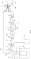
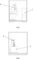
Figures 1A and1B schematically represent a particular embodiment for an installation intended to carry out dynamic corrosion and degradation tests on samples exposed to a medium in a melted state according to the present invention. -
Figure 2 represents a detailed cross-sectional view of the installation offigure 1B . -
Figure 3 represents a detailed view of a test-stand of the installation of the present invention, comprising a sample holder and an inductor. -
Figure 4 is a cross-sectional view of the test stand offigure 3 . -
Figure 5 represents a detailed cross-sectional view of the cooling device and the induction power system of the installation according to the invention. -
Figure 6 represents a detailed cross-sectional view of the tank of fluid and the pump of the installation of the present invention. -
Figure 7 schematically represents chamfered sample tubes sections prepared for butt welding with full penetration. -
- 1
- Installation for carrying out dynamic corrosion and degradation tests
- 2
- Hot pot of fluid
- 3
- Pipe (similar to test tube)
- 4
- Sample
- 5A
- Unheated sample holder
- 5B
- Heated sample holder
- 6
- Inductor for heating a heated sample holder
- 7
- Power system/supply
- 8
- Pump for circulating the fluid
- 9
- Heat exchanger (cooling device)
- 10
- DCS (digital control system)
- 11
- Air supply
- 12
- Drain tank
- 13
- Fluid
- 14
- Heating unit
- 15
- Pressure sensor
- 16
- Flow sensor
- 17
- Temperature sensor
- 18
- Pyrometer
- 19
- Air blower
- 21
- Tank insulation
- 22
- Chamfer
- The present invention relates to an
installation 1 to carry out dynamic corrosion and/or degradation tests on samples, preferablymetal samples 4 being in contact with a fluid circulating in apipe 3. - To this end, and as illustrated by
Figures 1A ,1B and2 , theinstallation 1 of the invention comprises a hot tank orpot 2 for heating up to desired temperature and storing a fluid and a circulation loop comprising apipe 3 in which the fluid circulates thanks to apump 8. Preferably, thepipe 3 is tilted from the horizontal plane to facilitate drainage and avoid problems of solidification of salt and, more preferably, thepipe 3 is tilted of about 4° from the horizontal plane. - According to the invention, the installation comprises several test points that will be called hereinafter "test stands", located at different locations along the
pipe 3. As illustrated byFigures 3 and 4 , each test-stand comprises a sample holder ortesting chamber 5B to hold, in use, asample 4 in a specific portion of saidpipe 3, and aheating unit 14 comprising an inductor orcoil 6 wrapped around thepipe 3 for heating thesample holder 5B and thesample 4. In this way, eachsample holder 5B is heated by aspecific inductor 6 in order to obtain a different, independently controlled temperature in all the portions ofpipe 3, each containing asample 4. In the installation of the present invention, these specific portions ofpipe 3 have the functionality of a test chamber in addition of that of containing the fluid. A power system/supply 7 for eachheating unit 14 andinductor 6 is provided near or within theinstallation 1. - According to a preferred embodiment, the
metal samples 4 are made of tubular portions of the metal to be tested that are inserted with butt welding connections in thepipe 3. Still preferably the welding connections are full penetration butt welds out of chamfered tube ends. For example, in the test pipe area, sections of specific stainless steel to be tested (e.g. SB 626 NO6230) may alternate with sections made of ordinary stainless steel (such as AISI 304 for example).Figure 7 schematically shows the chamfered tubes sections prepared for butt welding with full penetration. - According to another embodiment, the sections to be tested can be connected with other pipe sections using flanges, preferably non-conducting flanges. This solution has the advantage that the heat created locally does not propagate toward the whole pipe and further to the fluid. Alternately, the sample holder can comprise a series of pipe sections to be tested separated by non-conducting flanges. This solution could however suffer from sealing problems at high temperature.
- The fluid, for example a molten medium, circulating in the
pipe 3 of the loop has a temperature that is essentially constant, and is heated by heating means such as an electrical resistor (not shown) provided around or withinheating tank 2. Typically 50-100L molten salt circulate in the installation. - In this way, the installation of the present invention allows to provide a gradient of temperature between the circulating fluid and each sample holder, in order to simulate real conditions. This coupling between
inductor 6 andsample holder 5B allows a high flexibility in terms of thermal gradient between the molten salt and thetest tube samples 4, as well as improved accuracy thanks to fast and precise reaching of desired temperature specifically obtained by induction heating. As a result, this test configuration allows a better understanding of the behaviour of a fluid that is in contact with a metal of higher temperature. - A temperature difference up to 150°C between the fluid (molten salt) circulating in the
pipe 3 andmetal samples 4 can be obtained using an external induction heating. The critical element of the installation is to maintain this temperature difference between metal sample and fluid. Circulating fluid will permanently absorb a certain energy quantity from the hotter metal, with the consequence that the metal temperature will decrease, unless the latter is subject to a steady energy flow. This energy flow should be of the same order of magnitude as in real conditions, e.g. from 1 to 3 MW/m2 in the solar energy domain. - For example, in the CSP molten salt solar tower technology, the heat transfer fluid is a molten salt typically entering at 290°C in the solar receiver and coming out thereof at about 565°C. The surface temperature of the solar receiver panels is comprised between 500°C and more than 600°C or even 700°C, according to their position relative to the sun direction. Obviously, the elements of the solar receiver brought into contact with the molten salt are at different temperatures depending on their location. It is therefore important to consider these temperature differences during corrosion tests. To simulate molten salt solar circuit conditions,
samples 4 are installed at different locations in the loop circuit, in test stands, in which thepipe 3 acts as a test tube and is at a different temperature from the other test stands. The dynamic test loop of the present invention allows to modulate different temperature gradients between the molten medium and the test tubes (stands) so that to be close to real conditions. - According to a preferred embodiment of the present invention, the minimal temperature of the sample holder 5 will be in the range between 100 and 290°C and the maximal temperature will be in the range between 380 and 800°C, according to the specific fluid used (water, thermal oil or molten salt). These temperatures are obtained very quickly thanks to each
inductor 6 heating each portion of thepipe 3 comprising a sample-holder 5. - A
pump 8 is provided in order to circulate the fluid in thepipe 3, as illustrated byfigures 1A ,1B and6 . In case the tests are performed to simulate the molten salt in a CSP solar tower, the molten salt circulates at a velocity comprised between 3 and 6 m/s, preferably of 4m/s. As the test tubes are in fact heated portions of thepipe 3, the flow circulates in the same manner than in the tubes of a solar tower. The results of the tests on thesamples 4 are more precise and correspond more to the reality than in tests made in a separate chamber containing a bath. - The fluid used in the invention can be a molten salt such as a binary or ternary alkali nitrate molten salt (e.g. KNO3/NaNO3 ; KNO3/NaNO2/NaNO3), or a carbonate salt, or thermal oil.
- In a preferred embodiment of the present invention, the installation comprises an unheated test stand with an
unheated sample holder 5A and four heated test stands, where the fourheated sample holders 5B are heated respectively for example at 600°C, 625°C, 650°C and 675°C. These temperatures suitably simulate the level of temperature of the solar receiver panel surface according to its respective positions relative to the sun. - The
tank 2 comprises anexternal insulation 21 at its external surface to keep the molten salt at the desired temperature (Fig. 1A ). Theinstallation 1 can also comprise acooling device 9 to avoid the overheating of the molten medium (seeFigures 1A ,1B ,2 and5 ). Thecooling device 9 can comprise a heat exchanger (e.g. air or water heat exchanger). In case the fluid is molten salt, this cooling device allows for example to keep the salt at about 565°C, as in a CSP molten salt tower plant. - Advantageously, the
present installation 1 can be provided in the form of a shipping container. In this way, the installation is easily transportable and can be located close to the installation to be analyzed, such as at the base of a solar tower for example. - In use,
samples 4 are place on different sample holders 5. Each sample holder 5 is quickly, separately and independently heated at the desired temperature, by its assignedinductor 6, while the fluid located in thetank 2 is heated by an electric resistor. Once the fluid has reached the desired temperature intank 2, pump 8 circulates the fluid in the different test stands located on thepipe 3. Thesamples 4, which are hold at an accurate temperature, are then in contact with the fluid which is at another temperature. The turbulent flow of the fluid circulating in thepipe 3, in contact with thesamples 4, allows to obtain test conditions as close as possible to the real conditions. - After having been in contact with the fluid and removed from the
pipe 3, thesamples 4 are analyzed, for example by mass loss analysis, to determine the degradation and corrosion rate of the samples in contact with the fluid. Advantageously thepresent installation 1 permits to cycle the tests.
Claims (14)
- A dynamic corrosion and degradation testing installation (1) comprising :- a tank (2) for heating and storing, in use, a fluid at a given temperature;- a looped circuit comprising a pipe (3) containing the fluid during the tests, having a first end and a second end both connected to the tank (2);- a pump (8) for circulating the fluid in the pipe (3);- a plurality of test stands located at different locations along the pipe (3), each test stand comprising a sample holder or testing chamber (5B) holding, in use, a solid sample (4) in contact with the fluid and a heater (6), intended to heat said sample holder (5B); characterized in that each test stand comprises said sample holder (5B) to hold, in use, said solid sample (4) in a specific portion of said pipe (3), these specific portions of the pipe (3) havinge the functionality of a test chamber in addition to that of containing the fluid, a heating unit (14) comprising an inductor coil (6) wrapped around said portion of the pipe (3) and adapted to provide a steady energy flow and to ensure a gradient of temperature between the fluid and the solid sample (4) to be tested.
- The installation according to claim 1, characterized in that the portion of the pipe (3) made of the solid sample (4) to be tested is inserted in the looped circuit pipe (3) by welded connections at both ends or to connections using flanges.
- The installation according to claim 2, characterized in that the welded connections are full penetration butt welds out of chamfered tube ends.
- The installation according to claim 1, characterized in that the flanges are non-conducting flanges.
- The installation according to claim 1, characterized in that it comprises an electrical resistor provided around or within the tank (2) to heat the fluid therein.
- The installation according to claim 1, characterized in that the pipe (3) is tilted from the horizontal, preferably at about 4° from the horizontal.
- The installation according to claim 1 characterized in that the tank (2) comprises external insulation (21) and draining means (12)
- The installation according to claim 1, characterized in that it also comprises a cooling device (9) to avoid overheating of the fluid
- The installation according to claim 8, characterized in that the cooling device (9) comprises a heat exchanger.
- A shipping container comprising the installation according to anyone of claims 1 to 9.
- A method for carrying out dynamic corrosion and degradation tests on samples (4) being in contact with a fluid, by means of the installation according to any_one of claims 8 to 9, comprising at least the following steps of :- placing metal samples (4) on each of the test stands within the pipe (3) ;- heating the fluid contained in the tank (2) ;- circulating the fluid in the pipe (3) according to the looped circuit by activating the pump (8) ;- cooling the pipe (3) by means of cooling device (9) ;- heating the samples (4) in the test stands using the corresponding inductor (6) to provide at each heated test stand a steady heat flow and to create a temperature gradient between the fluid and the sample (4) ;- stopping the heating of the fluid and draining the fluid out of the installation, subsequently opening the test stands, removing the samples therefrom, and performing degradation tests on said solid samples (4).
- The method according to claim 11, characterized in that the samples (4) are heated in the test stands by the respective inductors (6), so that the steady heat flow is comprised between 1 and 3 MW/m2 and the temperature gradient between the fluid and the sample is up to 150°C.
- The method according to claim 11, characterized in that the degradation tests are weight loss measurements after descaling and micrographic cross-section examination.
- The method according to claim 11, characterized in that the fluid is a molten salt or thermal oil.
Applications Claiming Priority (2)
| Application Number | Priority Date | Filing Date | Title |
|---|---|---|---|
| EP19184129.5A EP3761005A1 (en) | 2019-07-03 | 2019-07-03 | Dynamic test loop for determining molten salt corrosion |
| PCT/EP2020/067786 WO2021001249A1 (en) | 2019-07-03 | 2020-06-25 | Dynamic test loop for determining molten salt corrosion |
Publications (3)
| Publication Number | Publication Date |
|---|---|
| EP3994445A1 EP3994445A1 (en) | 2022-05-11 |
| EP3994445C0 EP3994445C0 (en) | 2024-08-21 |
| EP3994445B1 true EP3994445B1 (en) | 2024-08-21 |
Family
ID=67145705
Family Applications (2)
| Application Number | Title | Priority Date | Filing Date |
|---|---|---|---|
| EP19184129.5A Withdrawn EP3761005A1 (en) | 2019-07-03 | 2019-07-03 | Dynamic test loop for determining molten salt corrosion |
| EP20733845.0A Active EP3994445B1 (en) | 2019-07-03 | 2020-06-25 | Dynamic test loop for determining molten salt corrosion |
Family Applications Before (1)
| Application Number | Title | Priority Date | Filing Date |
|---|---|---|---|
| EP19184129.5A Withdrawn EP3761005A1 (en) | 2019-07-03 | 2019-07-03 | Dynamic test loop for determining molten salt corrosion |
Country Status (11)
| Country | Link |
|---|---|
| US (1) | US20220349809A1 (en) |
| EP (2) | EP3761005A1 (en) |
| KR (1) | KR20220044729A (en) |
| CN (1) | CN114051582A (en) |
| AR (1) | AR119328A1 (en) |
| AU (1) | AU2020300781A1 (en) |
| CL (1) | CL2021003486A1 (en) |
| IL (1) | IL289494A (en) |
| MA (1) | MA56439A (en) |
| WO (1) | WO2021001249A1 (en) |
| ZA (1) | ZA202201466B (en) |
Families Citing this family (4)
| Publication number | Priority date | Publication date | Assignee | Title |
|---|---|---|---|---|
| CN113049483B (en) * | 2021-04-27 | 2022-12-09 | 中国科学院上海应用物理研究所 | An experimental device and method suitable for research on material corrosion in non-constant temperature flowing medium environment |
| CN113295604B (en) * | 2021-05-21 | 2024-02-06 | 中国石油化工股份有限公司 | Test device and test method for simulating dynamic corrosion of solid waste salt |
| CN115127950A (en) * | 2022-07-27 | 2022-09-30 | 西南石油大学 | High-temperature high-pressure oil well pipe erosion corrosion device capable of achieving multi-section temperature control |
| CN117030586B (en) * | 2023-08-09 | 2025-08-26 | 国能河北龙山发电有限责任公司 | A molten salt flow corrosion and thermal stability testing device |
Family Cites Families (13)
| Publication number | Priority date | Publication date | Assignee | Title |
|---|---|---|---|---|
| US4599217A (en) * | 1985-01-22 | 1986-07-08 | Exxon Chemical Patents Inc. | Corrosion simulator useful for heat exchangers condensing vapors containing water and method for using same |
| FR2671181B1 (en) * | 1990-12-31 | 1993-04-23 | Gaz De France | GENERALIZED HIGH-TEMPERATURE CORROSION TEST INSTALLATION. |
| US5503006A (en) * | 1993-08-31 | 1996-04-02 | Nalco Chemical Company | High temperature corrosion simulator |
| JP4167330B2 (en) * | 1998-05-29 | 2008-10-15 | 昌信 松村 | Channel corrosion resistance test apparatus and channel corrosion resistance test method using the same |
| WO2008115050A1 (en) * | 2007-03-19 | 2008-09-25 | Avantium International B.V. | Corrosion simulator and the correspondence method |
| CN101865816A (en) * | 2010-05-28 | 2010-10-20 | 北京科技大学 | A high temperature and high pressure loop spray corrosion simulation and electrochemical test experimental device |
| DE102012221673A1 (en) * | 2012-11-27 | 2014-05-28 | Humboldt-Universität Zu Berlin | Sample holder for test apparatus for testing of environmental effects on sample, has multiple fluid test portions formed at sample region that is in fluid communication with sample to expose fluid |
| CN103926191B (en) * | 2014-03-26 | 2019-01-04 | 中国石油化工股份有限公司 | Multiphase Flow and fluidised form simulated experiment piping installation and analogue experiment method |
| EP3032240B1 (en) * | 2014-12-11 | 2020-01-22 | Shell International Research Maatschappij B.V. | System and method for testing corrosive effect of a hydrocarbon on a component |
| ES2534850B2 (en) * | 2014-12-22 | 2015-09-08 | Universidad Complutense De Madrid | Equipment and procedure for testing high temperature materials and fluids such as salts, metals, alloys and glass in the molten state |
| CN106124393A (en) * | 2016-08-23 | 2016-11-16 | 上海交通大学 | Flowing accelerated corrosion assay device and using method thereof |
| US20180156760A1 (en) * | 2016-12-05 | 2018-06-07 | Government Of The United States Of America, As Represented By The Secretary Of Commerce | Inductive flash desorber |
| EP3947778A4 (en) * | 2019-05-01 | 2023-08-02 | A.O. Smith Corporation | System and method for predicting tank failure of a water heater |
-
2019
- 2019-07-03 EP EP19184129.5A patent/EP3761005A1/en not_active Withdrawn
-
2020
- 2020-06-25 CN CN202080047561.0A patent/CN114051582A/en active Pending
- 2020-06-25 MA MA056439A patent/MA56439A/en unknown
- 2020-06-25 AU AU2020300781A patent/AU2020300781A1/en not_active Abandoned
- 2020-06-25 KR KR1020227003481A patent/KR20220044729A/en not_active Abandoned
- 2020-06-25 EP EP20733845.0A patent/EP3994445B1/en active Active
- 2020-06-25 US US17/621,701 patent/US20220349809A1/en not_active Abandoned
- 2020-06-25 WO PCT/EP2020/067786 patent/WO2021001249A1/en not_active Ceased
- 2020-07-01 AR ARP200101864A patent/AR119328A1/en unknown
-
2021
- 2021-12-24 CL CL2021003486A patent/CL2021003486A1/en unknown
- 2021-12-29 IL IL289494A patent/IL289494A/en unknown
-
2022
- 2022-02-01 ZA ZA2022/01466A patent/ZA202201466B/en unknown
Also Published As
| Publication number | Publication date |
|---|---|
| US20220349809A1 (en) | 2022-11-03 |
| AU2020300781A1 (en) | 2022-01-27 |
| KR20220044729A (en) | 2022-04-11 |
| EP3994445A1 (en) | 2022-05-11 |
| EP3994445C0 (en) | 2024-08-21 |
| ZA202201466B (en) | 2023-11-29 |
| MA56439A (en) | 2022-05-11 |
| EP3761005A1 (en) | 2021-01-06 |
| IL289494A (en) | 2022-02-01 |
| WO2021001249A1 (en) | 2021-01-07 |
| AR119328A1 (en) | 2021-12-09 |
| CL2021003486A1 (en) | 2023-02-10 |
| CN114051582A (en) | 2022-02-15 |
Similar Documents
| Publication | Publication Date | Title |
|---|---|---|
| US20220349809A1 (en) | Dynamic test loop for determining molten salt corrosion | |
| Raiman et al. | Corrosion of 316H stainless steel in flowing FLiNaK salt | |
| Lee et al. | Enhanced flow boiling heat transfer on chromium coated zircaloy-4 using cold spray technique for accident tolerant fuel (ATF) materials | |
| US20170294242A1 (en) | In situ probe for measurement of liquidus temperature in a molten salt reactor | |
| US20070201608A1 (en) | Method for testing a fuel rod cladding tube and associated device | |
| Niu et al. | Effect of oxygen on fouling behavior in lead–bismuth coolant systems | |
| Ragheb et al. | Observations in transition boiling of subcooled water under forced convective conditions | |
| Cheung et al. | Development of a downward-facing nucleate boiling correlation for thermal hydraulics analysis | |
| Sohal et al. | Conceptual design of forced convection molten salt heat transfer testing loop | |
| Fisher et al. | Laboratory methods for determining corrosion rates under heat flux conditions | |
| Rozumová et al. | Comparison of corrosion behavior of the austenitic stainless steel 316 L in static and flowing liquid lead | |
| Goderis et al. | Phase change front tracking methods in a vertical tube-in-tube phase change material heat exchanger | |
| Borgohain et al. | Natural circulation experiments in a non-uniform diameter lead bismuth loop and validation of LeBENC code | |
| Petrie et al. | Single-phase, natural circulation annular flow measurements for cartridge loop irradiation experiments | |
| Tcharnotskaia et al. | Liquid lead-bismuth materials test loop | |
| Govinder et al. | External surface temperature measurements for the heat transfer analysis of internally heated cylindrical clad-tubes subjected to external forced convection bulk water coolant thermal-hydraulic conditions | |
| EP3239690B1 (en) | Apparatus and method for testing materials and fluids at a high temperature, such as salts, metals, alloys or glass in a melted state | |
| Sapin et al. | Pore-scale experimental study of boiling in porous media | |
| Kim et al. | High-temperature heat transport and storage using LBE alloy for concentrated solar power system | |
| Kiosidou et al. | Corrosion Testing Trade Study on Testing Methods in Molten Salts | |
| Gajbhiye et al. | Pretest in forced circulation molten salt heat transfer loop: Studies with thermia‐B | |
| O’Brien et al. | A multi-purpose thermal hydraulic test facility for support of advanced reactor technologies | |
| Kang | Effects of the location of side inflow holes on pool boiling heat transfer in a vertical annulus | |
| CN223513108U (en) | Nuclear power plant material crevice corrosion test device | |
| Evtikhin et al. | Lithium-vanadium experimental facility for blanket problems investigation |
Legal Events
| Date | Code | Title | Description |
|---|---|---|---|
| STAA | Information on the status of an ep patent application or granted ep patent |
Free format text: STATUS: UNKNOWN |
|
| STAA | Information on the status of an ep patent application or granted ep patent |
Free format text: STATUS: THE INTERNATIONAL PUBLICATION HAS BEEN MADE |
|
| PUAI | Public reference made under article 153(3) epc to a published international application that has entered the european phase |
Free format text: ORIGINAL CODE: 0009012 |
|
| STAA | Information on the status of an ep patent application or granted ep patent |
Free format text: STATUS: REQUEST FOR EXAMINATION WAS MADE |
|
| 17P | Request for examination filed |
Effective date: 20211202 |
|
| AK | Designated contracting states |
Kind code of ref document: A1 Designated state(s): AL AT BE BG CH CY CZ DE DK EE ES FI FR GB GR HR HU IE IS IT LI LT LU LV MC MK MT NL NO PL PT RO RS SE SI SK SM TR |
|
| RAP1 | Party data changed (applicant data changed or rights of an application transferred) |
Owner name: JOHN COCKERILL RENEWABLES S.A. |
|
| DAX | Request for extension of the european patent (deleted) | ||
| RAV | Requested validation state of the european patent: fee paid |
Extension state: TN Effective date: 20211202 Extension state: MA Effective date: 20211202 |
|
| GRAP | Despatch of communication of intention to grant a patent |
Free format text: ORIGINAL CODE: EPIDOSNIGR1 |
|
| STAA | Information on the status of an ep patent application or granted ep patent |
Free format text: STATUS: GRANT OF PATENT IS INTENDED |
|
| INTG | Intention to grant announced |
Effective date: 20240315 |
|
| GRAS | Grant fee paid |
Free format text: ORIGINAL CODE: EPIDOSNIGR3 |
|
| GRAA | (expected) grant |
Free format text: ORIGINAL CODE: 0009210 |
|
| STAA | Information on the status of an ep patent application or granted ep patent |
Free format text: STATUS: THE PATENT HAS BEEN GRANTED |
|
| AK | Designated contracting states |
Kind code of ref document: B1 Designated state(s): AL AT BE BG CH CY CZ DE DK EE ES FI FR GB GR HR HU IE IS IT LI LT LU LV MC MK MT NL NO PL PT RO RS SE SI SK SM TR |
|
| REG | Reference to a national code |
Ref country code: GB Ref legal event code: FG4D |
|
| REG | Reference to a national code |
Ref country code: CH Ref legal event code: EP |
|
| REG | Reference to a national code |
Ref country code: DE Ref legal event code: R096 Ref document number: 602020036209 Country of ref document: DE |
|
| REG | Reference to a national code |
Ref country code: IE Ref legal event code: FG4D |
|
| U01 | Request for unitary effect filed |
Effective date: 20240829 |
|
| U07 | Unitary effect registered |
Designated state(s): AT BE BG DE DK EE FI FR IT LT LU LV MT NL PT RO SE SI Effective date: 20240910 |
|
| PG25 | Lapsed in a contracting state [announced via postgrant information from national office to epo] |
Ref country code: NO Free format text: LAPSE BECAUSE OF FAILURE TO SUBMIT A TRANSLATION OF THE DESCRIPTION OR TO PAY THE FEE WITHIN THE PRESCRIBED TIME-LIMIT Effective date: 20241121 |
|
| PG25 | Lapsed in a contracting state [announced via postgrant information from national office to epo] |
Ref country code: PL Free format text: LAPSE BECAUSE OF FAILURE TO SUBMIT A TRANSLATION OF THE DESCRIPTION OR TO PAY THE FEE WITHIN THE PRESCRIBED TIME-LIMIT Effective date: 20240821 Ref country code: GR Free format text: LAPSE BECAUSE OF FAILURE TO SUBMIT A TRANSLATION OF THE DESCRIPTION OR TO PAY THE FEE WITHIN THE PRESCRIBED TIME-LIMIT Effective date: 20241122 |
|
| PG25 | Lapsed in a contracting state [announced via postgrant information from national office to epo] |
Ref country code: IS Free format text: LAPSE BECAUSE OF FAILURE TO SUBMIT A TRANSLATION OF THE DESCRIPTION OR TO PAY THE FEE WITHIN THE PRESCRIBED TIME-LIMIT Effective date: 20241221 |
|
| PG25 | Lapsed in a contracting state [announced via postgrant information from national office to epo] |
Ref country code: HR Free format text: LAPSE BECAUSE OF FAILURE TO SUBMIT A TRANSLATION OF THE DESCRIPTION OR TO PAY THE FEE WITHIN THE PRESCRIBED TIME-LIMIT Effective date: 20240821 |
|
| PG25 | Lapsed in a contracting state [announced via postgrant information from national office to epo] |
Ref country code: ES Free format text: LAPSE BECAUSE OF FAILURE TO SUBMIT A TRANSLATION OF THE DESCRIPTION OR TO PAY THE FEE WITHIN THE PRESCRIBED TIME-LIMIT Effective date: 20240821 Ref country code: RS Free format text: LAPSE BECAUSE OF FAILURE TO SUBMIT A TRANSLATION OF THE DESCRIPTION OR TO PAY THE FEE WITHIN THE PRESCRIBED TIME-LIMIT Effective date: 20241121 |
|
| PG25 | Lapsed in a contracting state [announced via postgrant information from national office to epo] |
Ref country code: RS Free format text: LAPSE BECAUSE OF FAILURE TO SUBMIT A TRANSLATION OF THE DESCRIPTION OR TO PAY THE FEE WITHIN THE PRESCRIBED TIME-LIMIT Effective date: 20241121 Ref country code: PL Free format text: LAPSE BECAUSE OF FAILURE TO SUBMIT A TRANSLATION OF THE DESCRIPTION OR TO PAY THE FEE WITHIN THE PRESCRIBED TIME-LIMIT Effective date: 20240821 Ref country code: NO Free format text: LAPSE BECAUSE OF FAILURE TO SUBMIT A TRANSLATION OF THE DESCRIPTION OR TO PAY THE FEE WITHIN THE PRESCRIBED TIME-LIMIT Effective date: 20241121 Ref country code: IS Free format text: LAPSE BECAUSE OF FAILURE TO SUBMIT A TRANSLATION OF THE DESCRIPTION OR TO PAY THE FEE WITHIN THE PRESCRIBED TIME-LIMIT Effective date: 20241221 Ref country code: HR Free format text: LAPSE BECAUSE OF FAILURE TO SUBMIT A TRANSLATION OF THE DESCRIPTION OR TO PAY THE FEE WITHIN THE PRESCRIBED TIME-LIMIT Effective date: 20240821 Ref country code: GR Free format text: LAPSE BECAUSE OF FAILURE TO SUBMIT A TRANSLATION OF THE DESCRIPTION OR TO PAY THE FEE WITHIN THE PRESCRIBED TIME-LIMIT Effective date: 20241122 Ref country code: ES Free format text: LAPSE BECAUSE OF FAILURE TO SUBMIT A TRANSLATION OF THE DESCRIPTION OR TO PAY THE FEE WITHIN THE PRESCRIBED TIME-LIMIT Effective date: 20240821 |
|
| PG25 | Lapsed in a contracting state [announced via postgrant information from national office to epo] |
Ref country code: SM Free format text: LAPSE BECAUSE OF FAILURE TO SUBMIT A TRANSLATION OF THE DESCRIPTION OR TO PAY THE FEE WITHIN THE PRESCRIBED TIME-LIMIT Effective date: 20240821 |
|
| PG25 | Lapsed in a contracting state [announced via postgrant information from national office to epo] |
Ref country code: CZ Free format text: LAPSE BECAUSE OF FAILURE TO SUBMIT A TRANSLATION OF THE DESCRIPTION OR TO PAY THE FEE WITHIN THE PRESCRIBED TIME-LIMIT Effective date: 20240821 |
|
| PG25 | Lapsed in a contracting state [announced via postgrant information from national office to epo] |
Ref country code: SK Free format text: LAPSE BECAUSE OF FAILURE TO SUBMIT A TRANSLATION OF THE DESCRIPTION OR TO PAY THE FEE WITHIN THE PRESCRIBED TIME-LIMIT Effective date: 20240821 |
|
| PLBE | No opposition filed within time limit |
Free format text: ORIGINAL CODE: 0009261 |
|
| STAA | Information on the status of an ep patent application or granted ep patent |
Free format text: STATUS: NO OPPOSITION FILED WITHIN TIME LIMIT |
|
| 26N | No opposition filed |
Effective date: 20250522 |
|
| REG | Reference to a national code |
Ref country code: CH Ref legal event code: H13 Free format text: ST27 STATUS EVENT CODE: U-0-0-H10-H13 (AS PROVIDED BY THE NATIONAL OFFICE) Effective date: 20260127 |
|
| PG25 | Lapsed in a contracting state [announced via postgrant information from national office to epo] |
Ref country code: MC Free format text: LAPSE BECAUSE OF FAILURE TO SUBMIT A TRANSLATION OF THE DESCRIPTION OR TO PAY THE FEE WITHIN THE PRESCRIBED TIME-LIMIT Effective date: 20240821 |
|
| GBPC | Gb: european patent ceased through non-payment of renewal fee |
Effective date: 20250625 |
|
| U90 | Renewal fees not paid: noting of loss of rights |
Free format text: RENEWAL FEE NOT PAID FOR YEAR 06 Effective date: 20260120 |
|
| PG25 | Lapsed in a contracting state [announced via postgrant information from national office to epo] |
Ref country code: GB Free format text: LAPSE BECAUSE OF NON-PAYMENT OF DUE FEES Effective date: 20250625 |
|
| PG25 | Lapsed in a contracting state [announced via postgrant information from national office to epo] |
Ref country code: IE Free format text: LAPSE BECAUSE OF NON-PAYMENT OF DUE FEES Effective date: 20250625 |
|
| VS25 | Lapsed in a validation state [announced via postgrant information from nat. office to epo] |
Ref country code: MA Free format text: LAPSE BECAUSE OF FAILURE TO SUBMIT A TRANSLATION OF THE DESCRIPTION OR TO PAY THE FEE WITHIN THE PRESCRIBED TIME-LIMIT; INVALID AB INITIO Effective date: 20200625 |
|
| PG25 | Lapsed in a contracting state [announced via postgrant information from national office to epo] |
Ref country code: CH Free format text: LAPSE BECAUSE OF NON-PAYMENT OF DUE FEES Effective date: 20250630 |
|
| U93 | Unitary patent lapsed |
Free format text: RENEWAL FEE NOT PAID Effective date: 20250630 |