EP3994068B1 - Leak-resistant tray and lid - Google Patents
Leak-resistant tray and lid Download PDFInfo
- Publication number
- EP3994068B1 EP3994068B1 EP20768738.5A EP20768738A EP3994068B1 EP 3994068 B1 EP3994068 B1 EP 3994068B1 EP 20768738 A EP20768738 A EP 20768738A EP 3994068 B1 EP3994068 B1 EP 3994068B1
- Authority
- EP
- European Patent Office
- Prior art keywords
- wall
- tray
- perimeter
- lid
- partition
- Prior art date
- Legal status (The legal status is an assumption and is not a legal conclusion. Google has not performed a legal analysis and makes no representation as to the accuracy of the status listed.)
- Active
Links
Images








Classifications
-
- B—PERFORMING OPERATIONS; TRANSPORTING
- B65—CONVEYING; PACKING; STORING; HANDLING THIN OR FILAMENTARY MATERIAL
- B65D—CONTAINERS FOR STORAGE OR TRANSPORT OF ARTICLES OR MATERIALS, e.g. BAGS, BARRELS, BOTTLES, BOXES, CANS, CARTONS, CRATES, DRUMS, JARS, TANKS, HOPPERS, FORWARDING CONTAINERS; ACCESSORIES, CLOSURES, OR FITTINGS THEREFOR; PACKAGING ELEMENTS; PACKAGES
- B65D1/00—Rigid or semi-rigid containers having bodies formed in one piece, e.g. by casting metallic material, by moulding plastics, by blowing vitreous material, by throwing ceramic material, by moulding pulped fibrous material or by deep-drawing operations performed on sheet material
- B65D1/34—Trays or like shallow containers
- B65D1/36—Trays or like shallow containers with moulded compartments or partitions
-
- B—PERFORMING OPERATIONS; TRANSPORTING
- B65—CONVEYING; PACKING; STORING; HANDLING THIN OR FILAMENTARY MATERIAL
- B65D—CONTAINERS FOR STORAGE OR TRANSPORT OF ARTICLES OR MATERIALS, e.g. BAGS, BARRELS, BOTTLES, BOXES, CANS, CARTONS, CRATES, DRUMS, JARS, TANKS, HOPPERS, FORWARDING CONTAINERS; ACCESSORIES, CLOSURES, OR FITTINGS THEREFOR; PACKAGING ELEMENTS; PACKAGES
- B65D2543/00—Lids or covers essentially for box-like containers
- B65D2543/00009—Details of lids or covers for rigid or semi-rigid containers
- B65D2543/00342—Central part of the lid
- B65D2543/00351—Dome-like
- B65D2543/00361—Dome-like placed on a tray like container
-
- B—PERFORMING OPERATIONS; TRANSPORTING
- B65—CONVEYING; PACKING; STORING; HANDLING THIN OR FILAMENTARY MATERIAL
- B65D—CONTAINERS FOR STORAGE OR TRANSPORT OF ARTICLES OR MATERIALS, e.g. BAGS, BARRELS, BOTTLES, BOXES, CANS, CARTONS, CRATES, DRUMS, JARS, TANKS, HOPPERS, FORWARDING CONTAINERS; ACCESSORIES, CLOSURES, OR FITTINGS THEREFOR; PACKAGING ELEMENTS; PACKAGES
- B65D2543/00—Lids or covers essentially for box-like containers
- B65D2543/00009—Details of lids or covers for rigid or semi-rigid containers
- B65D2543/00444—Contact between the container and the lid
- B65D2543/00453—Contact between the container and the lid in a peripheral U-shaped channel of the container
- B65D2543/00462—Contact between the container and the lid in a peripheral U-shaped channel of the container peripheral U-shaped channel of the lid
-
- B—PERFORMING OPERATIONS; TRANSPORTING
- B65—CONVEYING; PACKING; STORING; HANDLING THIN OR FILAMENTARY MATERIAL
- B65D—CONTAINERS FOR STORAGE OR TRANSPORT OF ARTICLES OR MATERIALS, e.g. BAGS, BARRELS, BOTTLES, BOXES, CANS, CARTONS, CRATES, DRUMS, JARS, TANKS, HOPPERS, FORWARDING CONTAINERS; ACCESSORIES, CLOSURES, OR FITTINGS THEREFOR; PACKAGING ELEMENTS; PACKAGES
- B65D43/00—Lids or covers for rigid or semi-rigid containers
- B65D43/02—Removable lids or covers
- B65D43/0202—Removable lids or covers without integral tamper element
- B65D43/0214—Removable lids or covers without integral tamper element secured only by friction or gravity
- B65D43/0218—Removable lids or covers without integral tamper element secured only by friction or gravity on both the inside and the outside of the mouth of the container
Definitions
- Containers for the storage and transport of food include a tray and a lid, which may be separate or interconnected (e.g., clamshell).
- the tray and/or lid may be made from container materials including one or more of molded fiber or paperboard, plastic, or metal (e.g., aluminum).
- metal e.g., aluminum
- an aluminum container is used in conjunction with a plastic lid, both components may be made of plastic, or molded fiber may be combined with plastics, and so on.
- such containers merely contain the food for a limited time (sufficient to transport the food from a restaurant to home), but do not have sufficient structural integrity to prevent leaks.
- Leaks may occur due to failure of the material itself, a penetration of liquid between the tray and the lid, or a failure of a clean seal between the tray and lid due to manufacturing error and/or difficulties. This problem is especially apparent in containers that are made from organic (e.g., containing cellulose) materials such as molded fiber. Chemical and/or wax additives added to molded fiber to create the container material may improve the container material resistance to failure or penetration, but may limit the compostability or other desired features. Similarly, molded fiber manufacturing, due to its form (geometry) and aesthetic limitations, has typically been limited to the egg tray and industrial packaging markets.
- Document US 2010/181226 A1 discloses a serving platter that includes a main body defining a serving area having a plurality of dividing walls separating the serving area into a plurality of serving sections for receiving food items therein for presentation to a person for eating and at least one partitioning wall separating each serving section into a primary serving well and a secondary serving well.
- the cover further includes a cover removably coupled to the main body and positionable between a transport configuration, wherein the cover is arranged above and seals the serving area, and a serving configuration, wherein the cover is arranged and sealed beneath the main body.
- the technology relates to a container having: a molded fiber tray having: a unitary fiber body defining at least one internal well, wherein the molded fiber body has a perimeter engaging wall extending upward from a perimeter rim of the molded fiber tray, the perimeter engaging wall has an inner surface, an outer surface, and an uppermost surface spanning the inner surface and the outer surface; and a molded fiber lid including: a unitary fiber body having at least one ceiling, and wherein the unitary fiber body defines a perimeter engaging receiver extending upward from a perimeter rim of the molded fiber lid, the perimeter engaging receiver at least partially defined by an inner wall, an outer wall, and an uppermost wall spanning the inner wall and the outer wall, wherein the perimeter engaging wall is configured to be removably received in the perimeter engaging receiver, wherein, when so received, the inner surface contacts the inner wall, the outer surface contacts the outer wall, and the uppermost surface contacts the uppermost wall, and wherein, when so received, the at least one internal well and the at least one ceiling define a substantially
- unitary fiber body of the molded fiber tray further includes at least one partition that subdivides the internal well into a plurality of wells, and wherein the unitary fiber body of the molded fiber lid defines at least one internal channel that subdivides the at least one ceiling into a plurality of ceilings, wherein the at least one internal channel is configured to mate with the at least one partition, and wherein, when so mated, each of the plurality of wells and plurality of ceilings define a discrete substantially sealed internal volume.
- the perimeter rim of the molded fiber tray is disposed substantially orthogonal to the outer surface and the inner surface.
- the perimeter rim of the molded finer tray has an outer rim disposed adjacent the outer wall and an inner rim disposed adjacent the inner wall, and wherein the inner rim is adjacent the at least one well.
- the perimeter rim of the molded fiber lid is disposed substantially orthogonal to the outer wall and the inner wall.
- the perimeter rim of the molded fiber lid has an outer rim disposed adjacent the outer surface and an inner rim disposed adjacent the inner surface, and wherein the molded fiber lid further includes at least one soffit disposed between the inner rim and the at least one ceiling.
- the molded fiber lid further includes at least one tab extending from the perimeter rim.
- the at least one partition has a major partition extending from a first side of the molded fiber tray to a second side of the molded fiber tray.
- the at least one partition further includes a minor partition extending from a third side of the molded fiber tray to the major partition.
- the uppermost surface of the perimeter engaging wall at least partially defines a groove.
- the groove is continuous.
- the at least one partition at least partially defines a groove.
- the technology in another aspect, relates to a container having: a molded fiber tray having: a unitary fiber body defining at least two internal wells, separated by a partition having a first well surface, a second well surface, and a partition uppermost surface spanning the first well surface and the second well surface, wherein the molded fiber body has a perimeter engaging wall extending upward from a perimeter rim of the molded fiber tray and at least partially surrounding both of the two internal wells, the perimeter engaging wall having an inner surface, an outer surface, and an uppermost surface spanning the inner surface and the outer surface, wherein the perimeter engaging wall uppermost surface at least partially defines a groove therein, and wherein the perimeter engaging wall uppermost surface is disposed at an elevation different than an elevation of the partition uppermost surface; and a molded fiber lid having: a unitary fiber body including at least one ceiling, a soffit extending from the at least one ceiling and defining an internal recess, a perimeter engaging receiver extending upward from a perimeter rim of the molded fiber lid,
- Containers described herein include a tray portion made of molded fiber and a mating lid portion made of molded fiber. Specific materials, as well as methods of making such trays and lids, are also described. In general, the trays and lids described are connected at an interface portion, typically around an entire perimeter of the tray and lib, though other interior interface portions may be present in certain examples as depicted herein.
- the interface portion includes a wall formed on the tray that is received in a receiver defined by the lid. In other examples, the receiver may be defined by the tray, while the wall may project from a bottom of the lid. Additional surfaces adjacent this wall and receiver structure further seal the container when closed. These additional surfaces (along with the surfaces of the wall and receiver) include a number of surfaces disposed at various angles to each other.
- the interface portion of the lid includes surfaces (again disposed at angles to each other) and curved transition surfaces.
- the interface portion of the lid is formed in a profile that matches, or substantially matches, the profile of the interface portion of the tray.
- these mating angled and curved surfaces form a reinforced structure that resists deformation due to forces that may be applied at any angle to the interface portion (e.g., during transport, if the container is dropped, or when the lid is pressed onto the tray).
- the contacting surfaces of the tray and lid define a convoluted path that resists leakage of liquid therebetween, e.g., due to increased pressure of the fluid therein.
- a convoluted path that resists leakage of liquid therebetween, e.g., due to increased pressure of the fluid therein.
- the liquid inside must travel a convoluted path to escape the container.
- This convoluted path is defined by the mating surfaces of the tray and lid.
- the change in orientation of the various surfaces along the potential fluid path are formed by the various angled surfaces, thus reinforcing the interface. This requires significantly higher internal liquid pressure for leakage to occur.
- Containers may be formed to include one or more internal wells for food. Wells are separated by internal partitions formed in the body of the tray.
- the lid includes a corresponding number and configuration of channels that mate with the upper portions of the partitions. This mating between the partitions and channels prevents leakage between the various internal wells (referred to herein as "cross-contamination").
- cross-contamination since the partitions are formed by the body of the tray itself, adjacent wells are not disposed on opposite sides of a single, thin portion of material. Rather, each well has a dedicated wall and adjacent walls are separated by ambient air. This allows hot and cold foods to be placed in different wells of the same container, without heat transfer there between due to conduction or cross-contamination of contents.
- Materials that may be used in the manufacture of the molded fiber tray and lid include those described in U.S. Patent No. 10,036,126 , entitled “Methods for Manufacturing Fiber-Based Beverage Lids,". These materials include, generally, a mixture of hardwood and softwood fibers, along with trace amounts of other additives, such as a strengthener, grease repellant, and water repellant. Contacting surfaces of the tray and lid may be both smooth, both rough, or one may be smooth and one may be rough. Roughness of the surface may be obtained by incorporating a mesh screen into the mold utilized for formation of the tray and/or lid. Alternatively, a surface may be roughened after manufacture of the tray or lid, for example, by mechanical processes.
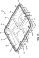
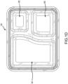
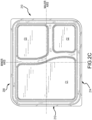
- FIGS. 1A-1H are various views of a molded fiber tray 100.
- the features described with regard to the tray 100 are primarily in reference to annotated FIG. 1A , an upper perspective view of the molded fiber tray 100.
- FIGS. 1B-1H are provided for further clarity and context, although not every feature is identified by number in every figure. Regardless, further construction details of the tray 100 would be apparent to a person of skill in the art upon reading the following description.
- the tray 100 is formed as a unitary molded fiber body 102, having features, contours, and surfaces, as described herein.
- the body 102 forms one or more wells (identified in FIG. 1A as W1, W2, and W3).
- Well W1 is separated from well W2 and well W3 by a major partition 104.
- major partition describes an internal partition between adjacent wells that terminates at a side (that is, a front side 106, a back side 108, a right side 110, and a left side 112) of the tray 100 itself.
- Well W2 and well W3 are separated by a minor partition 114.
- the term "minor partition” describes an internal partition between adjacent wells that terminates at a side (e.g., front 106, back 108, right 110, left 112) and another partition (e.g., major partition 104).
- Freestanding partitions e.g., partitions that project upward from a bottom of the tray 100 or that contact a single side or other partition
- the major partition 104 and minor partition 114 form some of the inner surfaces 116 of the various wells and include an uppermost surface 118 that spans the inner surfaces 116 of adjacent wells.
- each well W1, W2, W3 may be flat across the entire expanse thereof, or may include one or more steps 124 therein, which can define further structural integrity. Steps 124 may also be used to define a logo or other decorative feature into the tray 100. Structures having a plurality of steps may form a freestanding partition.
- the tray perimeter inner rim 120 is adjacent to a perimeter engaging wall (PEW) 126.
- This PEW 126 is a part of the sealing interface formed by engagement of the tray 100 and lid.
- the PEW 126 includes an inner surface 128 and an outer surface 130. Further details of the inner surface 128 and outer surface 130 are provided below.
- the inner surface 128 projects substantially upward from the perimeter inner rim 120, while the outer surface 130 projects substantially upward from a perimeter outer rim 132.
- the perimeter outer rim 132 projects from the side of the tray 100 and acts to help seat the lid on the tray 100, as described below.
- the PEW 126 also includes an uppermost surface 134 that spans the inner surface 128 and outer surface 130.
- the uppermost surface 134 may define therein a continuous groove 136 that extends the extent of the uppermost surface 134.
- the groove 136 may be intermittent or partial along one or more portions of the uppermost surface 134.
- the groove 136 enables the PEW 126 to resist deformation that may commonly occur when the lid is being engaged with the tray 100.
- the groove 136 is depicted as substantially curved in cross-sectional profile shape, but may be V-shaped.
- a profile of the curve 136 may define a semicircle or a smaller portion of a circle.
- a groove 136 may also be formed in the uppermost surface of a major or minor partition, as depicted and described elsewhere herein.
- the depicted tray 100 is a four-sided element defined a major axis and a minor axis. Opposing sides are parallel to a single axis. For example, sides 110 and 112 are parallel to the minor axis, while sides 106 and 108 are parallel to the major axis. Further, while the term “sides” is used to describe the outer lateral limits of the tray 100, the sides may further be defined by their location relative to a predetermined point of view. For example, the terms “front,” “back,” “right,” and “left,” may also be used to describe certain of the sides, in this case, the sides parallel to one of the axes.
- a particular well may be described based on the side(s) to which they are adjacent.
- Well W1 for example, is located adjacent the front 106, left 112, and back 108 sides of the tray 100, while well W3 is located adjacent the back 108 and right 110 sides and is further bounded by the major 104 and minor 114 partitions.
- the major and minor axes may also be used to describe the orientation of the various partitions, which may be straight, curved, at non-orthogonal angles to both the major and minor axes, etc.
- the depicted tray 100 includes four sides, trays having other configurations of sides, such as five, six, or eight, are also contemplated. Trays having an equal number of sides are most likely to be utilized commercially.
- the terms "top” 138 and "bottom” 140 are used to describe, respectively, the upper and lower limits of the tray 100.
- the tray body 102 is formed from a unitary piece of molded material, having a material thickness generally consistent along its entire exposed area, within manufacturing tolerances.
- the material may be molded to a material thickness of about 1.0 mm to about 1.3 mm. In examples, 1.15 mm has shown particularly desirable results and performance.
- Material thickness may be further modified based on the material (e.g., food) being held in the tray 100; that is, lighter food having a lower moisture content (e.g., popcorn) may not require as thick of a material as heavier food having a higher moisture content (e.g., stew).
- material thicknesses of about 0.8 mm to about 1.5 mm and about 0.6 mm to about 1.7 mm are also contemplated.
- the materials utilized in the manufacture of the tray 100 may be molded fiber, such as described in U.S. Patent No. 10,036,126 , entitled “Methods for Manufacturing Fiber-Based Beverage Lids,".
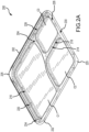
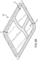
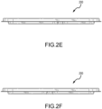
- FIGS. 2A-2H are various views of a molded fiber lid 200.
- the features described with regard to the lid 200 are primarily in reference to annotated FIG. 2A , a bottom perspective view of the molded fiber lid 200.
- FIGS. 2B-2H are provided for further clarity and context, although not every feature is identified by number in every figure. Regardless, further construction details of the lid 200 would be apparent to a person of skill in the art upon reading the following description.
- the lid 200 is formed as a unitary molded fiber body 202, having features, contours, and surfaces, as described herein.
- the body 202 forms one or more well ceilings (identified in FIG. 2A as well ceiling C1, well ceiling C2, and well ceiling C3).
- Well ceiling C1 is separated from well ceiling C2 and well ceiling C3 by an internal channel 204 that corresponds to the major partition 104 of the tray 100.
- Well ceiling C2 and well ceiling C3 are also separated by an internal channel 214 that corresponds to the minor partition 114 of the tray 100.
- Other channels may be present for any freestanding partitions and may support a ceiling of the tray, e.g., for a particularly wide well.
- the internal channels 204, 214 include an internal channel uppermost surface 218, which contacts the partition uppermost surface 118 when the lid 200 is engaged with the tray 100.
- Soffits 216 extend from the uppermost surface 218 to each well ceiling C1, C2, C3, thus locating the ceiling C1, C2, C3 of any particular well W1, W2, W3 below the uppermost surface 218 of the partitions 104, 114. This help to seal each individual well W1, W2, W3 from the others, thus preventing cross-contamination.
- the uppermost surface 218 of internal channels 204, 214 are generally level with a lid perimeter inner rim 220.
- the lid perimeter inner rim 220 is adjacent to a perimeter engaging receiver (PER) 226.
- This PER 226 is a part of the sealing interface formed by engagement of the tray 100 and lid 200.
- the PER 226 is defined on the sides by an inner wall 228 and an outer wall 230. Further details of the inner wall 228 and outer wall 230 (including their engagement with the inner surface 128 and outer surface 130 of the tray 100, respectively) are provided below.
- the inner wall 228 projects substantially upward from the perimeter inner rim 220, while the outer surface 230 projects substantially upward from a perimeter outer rim 232, which projects from the side of the lid 200.
- the PER 226 is also defined by an uppermost wall 234 that spans the inner wall 228 and outer wall 230.
- a pull tab 225 may extend from the perimeter outer rim 232, e.g., at one or more corners, to ease removal of the lid 200 from the tray 100.
- the lid 200 also has major and minor axes, as well as various sides 206, 208, 210, 212, as described above in the context of the tray 100 (these are depicted in FIG. 2C ).
- the lid 200 may also be manufactured of the same material as the tray 100.
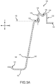
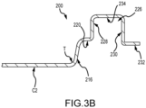
- FIGS. 3A-3B are partial sectional views of an example molded fiber tray 100 and an example molded fiber lid 200.
- FIG. 3C is a partial sectional view of a sealed molded fiber container 300 formed by the molded fiber tray 100 and molded fiber lid 200 of FIGS. 3A and 3B , respectively.
- FIGS. 3A-3C describe primarily the components, surfaces, and other features that form the interface of the sealed container 300, along with other aspects of the design. Not all of the depicted features are necessarily described further or in additional detail.
- FIG. 3A depicts a sectional view through the back side 108 of the tray 100, at well W2. Other sections around the various sides of the tray 100 would be configured similarly.
- FIG. 3A depicts a sectional view through the back side 108 of the tray 100, at well W2. Other sections around the various sides of the tray 100 would be configured similarly.
- 3A also depicts a standard Cartesian coordinate indicator having x and y axes.
- the components, surfaces, and other features described with regard to FIG. 3A may be measured relative to a Cartesian coordinate system as well known to persons of skill in the art. That is, a surface that is described as disposed an "a 30° angle to the x axis" would be understood to be disposed at an angle of 60° to the y axis. Further, the terms “horizontal” and “vertical” may also be used to describe surfaces oriented in the x axis only and y axis only, as understood in the art.
- transition describes a part of the body 102, 202 between two defined features of surface.
- One such transition T is depicted in FIG. 3A between the tray perimeter inner rim 120 and the PEW inner surface 128. Transitions T form a part of the component, feature, or surface to which it is adjacent. Thus, the depicted transition forms a part of the tray inner perimeter rim 120 and the PEW inner surface 128.
- the tray perimeter inner rim 120 is "adjacent" (as that term is used herein) to the PEW inner surface 128 (even in the presence of the transition T) because that transition T forms a part of each of those elements for the purposes of this description.
- Angular orientation of a transition T if not contemplated in the context of describing the angular orientation of an element of which it forms a part.
- the depicted PEW inner surface 128 is described as “vertical,” it does not include any horizontally-oriented parts, even though the transition T forms a part thereof. Not all transitions in the tray 100 are labeled in FIG. 3A , but will be apparent to a person of skill in the art.
- the inner well surface 116 is disposed at an angle to the y axis of about 5°, although angular ranges of about 0°, about 1°, about 2°, about 3°, about 4°, about 0° to about 10°, about 5° to about 15°, about 10° to about 20°, about 15° to about 25°, and about 20° to about 30° are also contemplated. Smaller angles are typically advantageous on walls that form a part of the major 104 or minor 114 partitions and may allow for improved sealing between adjacent wells, so as to prevent cross-contamination.
- the tray perimeter inner rim 120 is disposed horizontally and is coextensive with the major partition uppermost surface 118 (depicted in broken lines, for illustrative purposes).
- the tray perimeter inner rim 120 may be disposed at an angle to the horizontal, a horizontal orientation aids in reinforcing the PEW 126 as forces act vertically against the latter element.
- the tray perimeter inner rim 120 is able to deflect in a vertical direction, thereby absorbing forces applied to the PEW 126.
- the PEW inner surface 128 is vertical, as is the PEW outer surface 130; thus, the draft angle of the PEW 126 is 0°.
- Other draft angles from 0° up to and including each of 0.5°, 1.0°, 1.5°, 2.0°, and 2.5° are also contemplated.
- the PEW uppermost surface 134 defines a groove 136 that aids in absorbing forces applied to the PEW 126, specifically those applied when the lid 200 is forced onto the tray 100 to seal it.
- the tray perimeter outer rim 132 is horizontally disposed.
- a well outer surface 142 is also depicted.
- FIG. 3B depicts a sectional view through the back side 208 of the lid 200, at well ceiling C2. Other sections around the various sides 206, 210, 212 of the lid 200 would be configured similarly.
- FIG. 3B also depicts a standard Cartesian coordinate indicator having x and y axes; thus, the components, surfaces, and other features described with regard to FIG. 3B may be measured consistent with the descriptions provided above. Transitions T are also depicted, and are defined as described above.
- the well ceiling C2 is horizontal.
- the soffit 216 is disposed at an angle substantially similar or similar to that of the inner well surface 116.
- the lid perimeter inner rim 220 is disposed horizontally so as to engage with the tray perimeter inner rim 120.
- the PER inner wall 228 and PER outer wall 230 are angled so as to match the corresponding surfaces of the PEW (inner wall 128 and outer wall 130, respectively); thus, the draft angle of the PER 226 is 0°. Other draft angles, from 0° up to and including each of 0.5°, 1.0°, 1.5°, 2.0°, and 2.5° are also contemplated.
- the PER uppermost surface 234 defines the uppermost extent of the PER 226.
- the lid perimeter outer rim 232 is horizontally disposed.
- FIG. 3C depicts the interface section 301 of the container 300 that includes the tray 100 and lid 200 of FIGS. 3A and 3B , respectively, the section views of both of which are depicted and may be read in conjunction therewith. Not all features of the tray 100 and lid 200 are depicted. The dimensions of a number of features are depicted. The distance H P from the uppermost surface of the partition to the ceiling C2 of the lid 200 is depicted. This distance may be about 0.8cm (5/16"), about 1.3 cm (1/2"), or about 1.9 cm (3/4"). The height of the PEW 126 may be measured on either of the inner surface (at a height H I ) or the outer surface (at a height Ho).
- Either height may be about 0.8cm (5/16"), about 1.3cm (1/2"), or about 1.9 cm (3/4").
- the width W of the PEW 126 may be a similar distance to the heights noted above.
- the combination of small draft angles of each of the partitions, the internal recesses, the PEW 126, and the PER 226, in combination with the distances described above, help seal the various wells against leakage between adjacent wells and external to the container.
- the distances described above form a long path that any liquid must be able to penetrate in order for leakage to occur.
- FIG. 3C also depicts the path that a liquid contained in the well would be required to follow to leak from the interface.
- a particular advantage of the depicted configuration is the number of sealing surfaces in the interface portion. Those sealing surfaces are numbered 1-7, as counted from a hypothetical entry location of liquid to a hypothetical exit location.
- Sealing surface 1 is located between the inner well surface 116 and the soffit 126.
- Sealing surface 2 is disposed between the tray perimeter inner rim 120 and the lid perimeter inner rim 220.
- Sealing surface 3 is between PEW inner surface 128 and PER inner wall 228.
- Sealing surface 4 is between a first portion of PEW uppermost surface 134 and a first portion of PER uppermost wall 234.
- the groove 136 defines a small volume into which any liquid that may penetrate past sealing surfaces 1-4 may be contained, so as to limit leakage. Thus, the groove 136 acts as a liquid pressure relief, even if all of sealing surfaces 1-4 fail.
- Sealing surface 5 is between a second portion of PEW uppermost surface 134 and a second portion of PER uppermost wall 234.
- Sealing surface 6 is between the PEW outer surface 130 and the PER outer wall 230.
- Sealing surface 7 is between the tray outer perimeter rim 132 and the lid perimeter outer rim 232.
- FIG. 4 is a partial view of a lock 400 formed in the molded container 300.
- the lock 400 may be in the form of a projection 402 that extends above a partition uppermost surface 118 of the tray 100, which may help seal the container 300 in a location distal from the PEW 126 and PER 226.
- the width of the projection 402 may be substantially similar to that of a throat 404 of a keeper 406 formed on the lid 200 (more specifically, the internal channel uppermost surface thereof 218).
- Use of the lock 400 may improve the sealing functionality between the tray 100 and lid 200 of the container 300.
- FIG. 5 is another example of a molded fiber tray 500.
- the features depicted in FIG. 5 are generally similar to those depicted in FIG. 1A , as such, the features are not specifically numbered or described, but would be apparent to a person of ordinary skill in the art, upon reading the above disclosure.
- One difference between the depicted tray 500 and the tray depicted above is the inclusion of partition grooves 501 defined by the uppermost surface 518 of both the major partition 504 and the minor partition 514.
- the partition groove 501 may be disposed on only one partition 504, 514.
- the depicted groove 501 includes both narrow portions 501a and wide portions 501b.
- the narrow portions 501a are disposed generally on the narrower width portions of the partitions 504, 514.
- the wide portions 501b are disposed proximate the intersection of the major partition 504 and minor partition 514 and near the ends of those features proximate the PEW 526.
- this inner groove 501 performs much of the same functionality as the groove 536 disposed on the PEW 526.
- FIG. 6 depicts another example of a molded fiber lid 600.
- the features depicted in FIG. 6 are generally similar to those depicted in FIG. 2A , as such, the features are not specifically numbered or described, but would be apparent to a person of ordinary skill in the art, upon reading the above disclosure.
- the depicted lid 600 also includes a groove 601 in the PER uppermost surface 634. This groove 601 is configured to mate with the groove defined by the PEW, e.g., as depicted in FIG. 1A . These mating grooves may further improve the sealing capability between the PEW and the PER.
Landscapes
- Engineering & Computer Science (AREA)
- Mechanical Engineering (AREA)
- Ceramic Engineering (AREA)
- Closures For Containers (AREA)
Description
- This application is being filed on August 19, 2020, as a
PCT International Patent Application and claims priority to and the benefit of U.S. Provisional Patent Application Serial No. 62/889,006, filed August 19, 2019 - Containers for the storage and transport of food include a tray and a lid, which may be separate or interconnected (e.g., clamshell). The tray and/or lid may be made from container materials including one or more of molded fiber or paperboard, plastic, or metal (e.g., aluminum). In some cases, an aluminum container is used in conjunction with a plastic lid, both components may be made of plastic, or molded fiber may be combined with plastics, and so on. Often, such containers merely contain the food for a limited time (sufficient to transport the food from a restaurant to home), but do not have sufficient structural integrity to prevent leaks. Leaks may occur due to failure of the material itself, a penetration of liquid between the tray and the lid, or a failure of a clean seal between the tray and lid due to manufacturing error and/or difficulties. This problem is especially apparent in containers that are made from organic (e.g., containing cellulose) materials such as molded fiber. Chemical and/or wax additives added to molded fiber to create the container material may improve the container material resistance to failure or penetration, but may limit the compostability or other desired features. Similarly, molded fiber manufacturing, due to its form (geometry) and aesthetic limitations, has typically been limited to the egg tray and industrial packaging markets.
DocumentUS 2010/181226 A1 discloses a serving platter that includes a main body defining a serving area having a plurality of dividing walls separating the serving area into a plurality of serving sections for receiving food items therein for presentation to a person for eating and at least one partitioning wall separating each serving section into a primary serving well and a secondary serving well. The cover further includes a cover removably coupled to the main body and positionable between a transport configuration, wherein the cover is arranged above and seals the serving area, and a serving configuration, wherein the cover is arranged and sealed beneath the main body. - In one aspect, the technology relates to a container having: a molded fiber tray having: a unitary fiber body defining at least one internal well, wherein the molded fiber body has a perimeter engaging wall extending upward from a perimeter rim of the molded fiber tray, the perimeter engaging wall has an inner surface, an outer surface, and an uppermost surface spanning the inner surface and the outer surface; and a molded fiber lid including: a unitary fiber body having at least one ceiling, and wherein the unitary fiber body defines a perimeter engaging receiver extending upward from a perimeter rim of the molded fiber lid, the perimeter engaging receiver at least partially defined by an inner wall, an outer wall, and an uppermost wall spanning the inner wall and the outer wall, wherein the perimeter engaging wall is configured to be removably received in the perimeter engaging receiver, wherein, when so received, the inner surface contacts the inner wall, the outer surface contacts the outer wall, and the uppermost surface contacts the uppermost wall, and wherein, when so received, the at least one internal well and the at least one ceiling define a substantially sealed internal volume. In an example, unitary fiber body of the molded fiber tray further includes at least one partition that subdivides the internal well into a plurality of wells, and wherein the unitary fiber body of the molded fiber lid defines at least one internal channel that subdivides the at least one ceiling into a plurality of ceilings, wherein the at least one internal channel is configured to mate with the at least one partition, and wherein, when so mated, each of the plurality of wells and plurality of ceilings define a discrete substantially sealed internal volume. In another example, the perimeter rim of the molded fiber tray is disposed substantially orthogonal to the outer surface and the inner surface. In yet another example, the perimeter rim of the molded finer tray has an outer rim disposed adjacent the outer wall and an inner rim disposed adjacent the inner wall, and wherein the inner rim is adjacent the at least one well. In still another example, the perimeter rim of the molded fiber lid is disposed substantially orthogonal to the outer wall and the inner wall.
- In another example of the above aspect, the perimeter rim of the molded fiber lid has an outer rim disposed adjacent the outer surface and an inner rim disposed adjacent the inner surface, and wherein the molded fiber lid further includes at least one soffit disposed between the inner rim and the at least one ceiling. In an example, the molded fiber lid further includes at least one tab extending from the perimeter rim. In another example, the at least one partition has a major partition extending from a first side of the molded fiber tray to a second side of the molded fiber tray. In yet another example, the at least one partition further includes a minor partition extending from a third side of the molded fiber tray to the major partition. According to the invention the uppermost surface of the perimeter engaging wall at least partially defines a groove. In another example, the groove is continuous. In another example, the at least one partition at least partially defines a groove.
- In another aspect, the technology relates to a container having: a molded fiber tray having: a unitary fiber body defining at least two internal wells, separated by a partition having a first well surface, a second well surface, and a partition uppermost surface spanning the first well surface and the second well surface, wherein the molded fiber body has a perimeter engaging wall extending upward from a perimeter rim of the molded fiber tray and at least partially surrounding both of the two internal wells, the perimeter engaging wall having an inner surface, an outer surface, and an uppermost surface spanning the inner surface and the outer surface, wherein the perimeter engaging wall uppermost surface at least partially defines a groove therein, and wherein the perimeter engaging wall uppermost surface is disposed at an elevation different than an elevation of the partition uppermost surface; and a molded fiber lid having: a unitary fiber body including at least one ceiling, a soffit extending from the at least one ceiling and defining an internal recess, a perimeter engaging receiver extending upward from a perimeter rim of the molded fiber lid, the perimeter engaging receiver at least partially defined by an inner wall, an outer wall, and an uppermost wall spanning the inner wall and the outer wall, wherein the partition is configured to be removably received in the internal recess, wherein, when so received, the soffit contacts at least one of the first well wall and the second well wall, wherein the perimeter engaging wall is configured to be removably received in the perimeter engaging receiver, wherein, when so received, the inner surface contacts the inner wall, the outer surface contacts the outer wall, and the uppermost surface contacts the uppermost wall, and wherein, when so received, the at least one internal well and the at least one ceiling define a substantially sealed internal volume.
- There are shown in the drawings examples that are presently preferred, it being understood, however, that the invention is not limited to the precise arrangements and configurations shown.
-
FIGS. 1A-1H are various views of an example of a molded fiber tray. -
FIGS. 2A-2H are various views of an example of a molded fiber lid. -
FIGS. 3A-3B are partial sectional views of an example molded fiber tray and an example molded fiber lid. -
FIG. 3C is a partial sectional view of a sealed molded fiber container formed by the molded fiber tray and molded fiber lid ofFIGS. 3A and3B , respectively. -
FIG. 4 is a partial view of a lock formed in the molded container. -
FIG. 5 is another example of a molded fiber tray. -
FIG. 6 depicts another example of a molded fiber lid. - Containers described herein include a tray portion made of molded fiber and a mating lid portion made of molded fiber. Specific materials, as well as methods of making such trays and lids, are also described. In general, the trays and lids described are connected at an interface portion, typically around an entire perimeter of the tray and lib, though other interior interface portions may be present in certain examples as depicted herein. The interface portion includes a wall formed on the tray that is received in a receiver defined by the lid. In other examples, the receiver may be defined by the tray, while the wall may project from a bottom of the lid. Additional surfaces adjacent this wall and receiver structure further seal the container when closed. These additional surfaces (along with the surfaces of the wall and receiver) include a number of surfaces disposed at various angles to each other. These various surfaces are connected to adjacent surfaces at curved transition surfaces. It has been determined that curved transition surfaces are more structurally sound and resist deformation better than sharp transition surfaces. The interface portion of the lid includes surfaces (again disposed at angles to each other) and curved transition surfaces. The interface portion of the lid is formed in a profile that matches, or substantially matches, the profile of the interface portion of the tray. Thus, when the interface portion of the tray and lid are engaged, these mating angled and curved surfaces form a reinforced structure that resists deformation due to forces that may be applied at any angle to the interface portion (e.g., during transport, if the container is dropped, or when the lid is pressed onto the tray).
- The contacting surfaces of the tray and lid define a convoluted path that resists leakage of liquid therebetween, e.g., due to increased pressure of the fluid therein. For example, if the filled, closed container is being acted upon by a vertical downward force (e.g., if it is packed in the bottom of a full carrying bag), the liquid inside must travel a convoluted path to escape the container. This convoluted path is defined by the mating surfaces of the tray and lid. The change in orientation of the various surfaces along the potential fluid path are formed by the various angled surfaces, thus reinforcing the interface. This requires significantly higher internal liquid pressure for leakage to occur.
- Containers may be formed to include one or more internal wells for food. Wells are separated by internal partitions formed in the body of the tray. The lid includes a corresponding number and configuration of channels that mate with the upper portions of the partitions. This mating between the partitions and channels prevents leakage between the various internal wells (referred to herein as "cross-contamination"). Further, since the partitions are formed by the body of the tray itself, adjacent wells are not disposed on opposite sides of a single, thin portion of material. Rather, each well has a dedicated wall and adjacent walls are separated by ambient air. This allows hot and cold foods to be placed in different wells of the same container, without heat transfer there between due to conduction or cross-contamination of contents.
- Materials that may be used in the manufacture of the molded fiber tray and lid include those described in
U.S. Patent No. 10,036,126 -
FIGS. 1A-1H are various views of a moldedfiber tray 100. The features described with regard to thetray 100 are primarily in reference to annotatedFIG. 1A , an upper perspective view of the moldedfiber tray 100.FIGS. 1B-1H depict other views of the tray 100: bottom perspective, top, bottom, front, back, right side, left side.FIGS. 1B-1H are provided for further clarity and context, although not every feature is identified by number in every figure. Regardless, further construction details of thetray 100 would be apparent to a person of skill in the art upon reading the following description. - The
tray 100 is formed as a unitary moldedfiber body 102, having features, contours, and surfaces, as described herein. Thebody 102 forms one or more wells (identified inFIG. 1A as W1, W2, and W3). Well W1 is separated from well W2 and well W3 by amajor partition 104. As used herein, the term "major partition" describes an internal partition between adjacent wells that terminates at a side (that is, afront side 106, aback side 108, aright side 110, and a left side 112) of thetray 100 itself. Well W2 and well W3 are separated by aminor partition 114. As used herein, the term "minor partition" describes an internal partition between adjacent wells that terminates at a side (e.g.,front 106, back 108, right 110, left 112) and another partition (e.g., major partition 104). Freestanding partitions (e.g., partitions that project upward from a bottom of thetray 100 or that contact a single side or other partition) may also be utilized, for example, to disrupt fluid flow within the container to reduce or eliminate "sloshing" of liquids therein. Themajor partition 104 andminor partition 114 form some of theinner surfaces 116 of the various wells and include anuppermost surface 118 that spans theinner surfaces 116 of adjacent wells. In the depicted example, theuppermost surface 118 of the major 104 andminor partitions 114 are level with a tray perimeterinner rim 120. Thefloor 122 of each well W1, W2, W3 may be flat across the entire expanse thereof, or may include one ormore steps 124 therein, which can define further structural integrity.Steps 124 may also be used to define a logo or other decorative feature into thetray 100. Structures having a plurality of steps may form a freestanding partition. - The tray perimeter
inner rim 120 is adjacent to a perimeter engaging wall (PEW) 126. ThisPEW 126 is a part of the sealing interface formed by engagement of thetray 100 and lid. ThePEW 126 includes aninner surface 128 and anouter surface 130. Further details of theinner surface 128 andouter surface 130 are provided below. Theinner surface 128 projects substantially upward from the perimeterinner rim 120, while theouter surface 130 projects substantially upward from a perimeterouter rim 132. The perimeterouter rim 132 projects from the side of thetray 100 and acts to help seat the lid on thetray 100, as described below. ThePEW 126 also includes anuppermost surface 134 that spans theinner surface 128 andouter surface 130. Theuppermost surface 134 may define therein acontinuous groove 136 that extends the extent of theuppermost surface 134. In other examples, thegroove 136 may be intermittent or partial along one or more portions of theuppermost surface 134. Thegroove 136 enables thePEW 126 to resist deformation that may commonly occur when the lid is being engaged with thetray 100. Thegroove 136 is depicted as substantially curved in cross-sectional profile shape, but may be V-shaped. In another example, a profile of thecurve 136 may define a semicircle or a smaller portion of a circle. In examples, agroove 136 may also be formed in the uppermost surface of a major or minor partition, as depicted and described elsewhere herein. - In general, the depicted
tray 100 is a four-sided element defined a major axis and a minor axis. Opposing sides are parallel to a single axis. For example, sides 110 and 112 are parallel to the minor axis, whilesides tray 100, the sides may further be defined by their location relative to a predetermined point of view. For example, the terms "front," "back," "right," and "left," may also be used to describe certain of the sides, in this case, the sides parallel to one of the axes. Thus, location of a particular well, for example, may be described based on the side(s) to which they are adjacent. Well W1, for example, is located adjacent the front 106, left 112, and back 108 sides of thetray 100, while well W3 is located adjacent the back 108 and right 110 sides and is further bounded by the major 104 and minor 114 partitions. The major and minor axes may also be used to describe the orientation of the various partitions, which may be straight, curved, at non-orthogonal angles to both the major and minor axes, etc. While the depictedtray 100 includes four sides, trays having other configurations of sides, such as five, six, or eight, are also contemplated. Trays having an equal number of sides are most likely to be utilized commercially. The terms "top" 138 and "bottom" 140 are used to describe, respectively, the upper and lower limits of thetray 100. - As noted, the
tray body 102 is formed from a unitary piece of molded material, having a material thickness generally consistent along its entire exposed area, within manufacturing tolerances. In examples, the material may be molded to a material thickness of about 1.0 mm to about 1.3 mm. In examples, 1.15 mm has shown particularly desirable results and performance. Material thickness may be further modified based on the material (e.g., food) being held in thetray 100; that is, lighter food having a lower moisture content (e.g., popcorn) may not require as thick of a material as heavier food having a higher moisture content (e.g., stew). Thus, material thicknesses of about 0.8 mm to about 1.5 mm and about 0.6 mm to about 1.7 mm are also contemplated. The materials utilized in the manufacture of thetray 100 may be molded fiber, such as described inU.S. Patent No. 10,036,126 -
FIGS. 2A-2H are various views of a moldedfiber lid 200. The features described with regard to thelid 200 are primarily in reference to annotatedFIG. 2A , a bottom perspective view of the moldedfiber lid 200.FIGS. 2B-2H depict other views of the lid 200: top perspective, top, bottom, front, back, right side, left side.FIGS. 2B-2H are provided for further clarity and context, although not every feature is identified by number in every figure. Regardless, further construction details of thelid 200 would be apparent to a person of skill in the art upon reading the following description. - The
lid 200 is formed as a unitary moldedfiber body 202, having features, contours, and surfaces, as described herein. Thebody 202 forms one or more well ceilings (identified inFIG. 2A as well ceiling C1, well ceiling C2, and well ceiling C3). Well ceiling C1 is separated from well ceiling C2 and well ceiling C3 by aninternal channel 204 that corresponds to themajor partition 104 of thetray 100. Well ceiling C2 and well ceiling C3 are also separated by aninternal channel 214 that corresponds to theminor partition 114 of thetray 100. Other channels may be present for any freestanding partitions and may support a ceiling of the tray, e.g., for a particularly wide well. Theinternal channels uppermost surface 218, which contacts the partitionuppermost surface 118 when thelid 200 is engaged with thetray 100.Soffits 216 extend from theuppermost surface 218 to each well ceiling C1, C2, C3, thus locating the ceiling C1, C2, C3 of any particular well W1, W2, W3 below theuppermost surface 218 of thepartitions uppermost surface 218 ofinternal channels inner rim 220. - The lid perimeter
inner rim 220 is adjacent to a perimeter engaging receiver (PER) 226. ThisPER 226 is a part of the sealing interface formed by engagement of thetray 100 andlid 200. ThePER 226 is defined on the sides by aninner wall 228 and anouter wall 230. Further details of theinner wall 228 and outer wall 230 (including their engagement with theinner surface 128 andouter surface 130 of thetray 100, respectively) are provided below. Theinner wall 228 projects substantially upward from the perimeterinner rim 220, while theouter surface 230 projects substantially upward from a perimeterouter rim 232, which projects from the side of thelid 200. ThePER 226 is also defined by anuppermost wall 234 that spans theinner wall 228 andouter wall 230. Apull tab 225 may extend from the perimeterouter rim 232, e.g., at one or more corners, to ease removal of thelid 200 from thetray 100. Thelid 200 also has major and minor axes, as well asvarious sides FIG. 2C ). Thelid 200 may also be manufactured of the same material as thetray 100. -
FIGS. 3A-3B are partial sectional views of an example moldedfiber tray 100 and an example moldedfiber lid 200.FIG. 3C is a partial sectional view of a sealed moldedfiber container 300 formed by the moldedfiber tray 100 and moldedfiber lid 200 ofFIGS. 3A and3B , respectively.FIGS. 3A-3C describe primarily the components, surfaces, and other features that form the interface of the sealedcontainer 300, along with other aspects of the design. Not all of the depicted features are necessarily described further or in additional detail. Specifically,FIG. 3A depicts a sectional view through theback side 108 of thetray 100, at well W2. Other sections around the various sides of thetray 100 would be configured similarly.FIG. 3A also depicts a standard Cartesian coordinate indicator having x and y axes. The components, surfaces, and other features described with regard toFIG. 3A may be measured relative to a Cartesian coordinate system as well known to persons of skill in the art. That is, a surface that is described as disposed an "a 30° angle to the x axis" would be understood to be disposed at an angle of 60° to the y axis. Further, the terms "horizontal" and "vertical" may also be used to describe surfaces oriented in the x axis only and y axis only, as understood in the art. Unless otherwise specified, angular orientations of components, surfaces, and features describe the orientation of surfaces of thetray 100 that engage with surfaces of thelid 200, since that engagement is relevant to the function of the interface. As used herein, the term "transition" describes a part of thebody FIG. 3A between the tray perimeterinner rim 120 and the PEWinner surface 128. Transitions T form a part of the component, feature, or surface to which it is adjacent. Thus, the depicted transition forms a part of the trayinner perimeter rim 120 and the PEWinner surface 128. Thus, it will be understood that the tray perimeterinner rim 120 is "adjacent" (as that term is used herein) to the PEW inner surface 128 (even in the presence of the transition T) because that transition T forms a part of each of those elements for the purposes of this description. Angular orientation of a transition T, however, if not contemplated in the context of describing the angular orientation of an element of which it forms a part. Thus, assuming the depicted PEWinner surface 128 is described as "vertical," it does not include any horizontally-oriented parts, even though the transition T forms a part thereof. Not all transitions in thetray 100 are labeled inFIG. 3A , but will be apparent to a person of skill in the art. - The
inner well surface 116 is disposed at an angle to the y axis of about 5°, although angular ranges of about 0°, about 1°, about 2°, about 3°, about 4°, about 0° to about 10°, about 5° to about 15°, about 10° to about 20°, about 15° to about 25°, and about 20° to about 30° are also contemplated. Smaller angles are typically advantageous on walls that form a part of the major 104 or minor 114 partitions and may allow for improved sealing between adjacent wells, so as to prevent cross-contamination. The tray perimeterinner rim 120 is disposed horizontally and is coextensive with the major partition uppermost surface 118 (depicted in broken lines, for illustrative purposes). While the tray perimeterinner rim 120 may be disposed at an angle to the horizontal, a horizontal orientation aids in reinforcing thePEW 126 as forces act vertically against the latter element. Thus, the tray perimeterinner rim 120 is able to deflect in a vertical direction, thereby absorbing forces applied to thePEW 126. The PEWinner surface 128 is vertical, as is the PEWouter surface 130; thus, the draft angle of thePEW 126 is 0°. Other draft angles, from 0° up to and including each of 0.5°, 1.0°, 1.5°, 2.0°, and 2.5° are also contemplated. While even larger draft angles may be utilized, it has been determined that the above-referenced draft angles provide the most desired performance for all types of contained foods, that is those with high to low liquid contents. The PEWuppermost surface 134 defines agroove 136 that aids in absorbing forces applied to thePEW 126, specifically those applied when thelid 200 is forced onto thetray 100 to seal it. The tray perimeterouter rim 132 is horizontally disposed. A wellouter surface 142 is also depicted. -
FIG. 3B depicts a sectional view through theback side 208 of thelid 200, at well ceiling C2. Other sections around thevarious sides lid 200 would be configured similarly.FIG. 3B also depicts a standard Cartesian coordinate indicator having x and y axes; thus, the components, surfaces, and other features described with regard toFIG. 3B may be measured consistent with the descriptions provided above. Transitions T are also depicted, and are defined as described above. The well ceiling C2 is horizontal. Thesoffit 216 is disposed at an angle substantially similar or similar to that of theinner well surface 116. The lid perimeterinner rim 220 is disposed horizontally so as to engage with the tray perimeterinner rim 120. The PERinner wall 228 and PERouter wall 230 are angled so as to match the corresponding surfaces of the PEW (inner wall 128 andouter wall 130, respectively); thus, the draft angle of thePER 226 is 0°. Other draft angles, from 0° up to and including each of 0.5°, 1.0°, 1.5°, 2.0°, and 2.5° are also contemplated. The PERuppermost surface 234 defines the uppermost extent of thePER 226. The lid perimeterouter rim 232 is horizontally disposed. -
FIG. 3C depicts theinterface section 301 of thecontainer 300 that includes thetray 100 andlid 200 ofFIGS. 3A and3B , respectively, the section views of both of which are depicted and may be read in conjunction therewith. Not all features of thetray 100 andlid 200 are depicted. The dimensions of a number of features are depicted. The distance HP from the uppermost surface of the partition to the ceiling C2 of thelid 200 is depicted. This distance may be about 0.8cm (5/16"), about 1.3 cm (1/2"), or about 1.9 cm (3/4"). The height of thePEW 126 may be measured on either of the inner surface (at a height HI) or the outer surface (at a height Ho). Either height may be about 0.8cm (5/16"), about 1.3cm (1/2"), or about 1.9 cm (3/4"). The width W of thePEW 126 may be a similar distance to the heights noted above. The combination of small draft angles of each of the partitions, the internal recesses, thePEW 126, and thePER 226, in combination with the distances described above, help seal the various wells against leakage between adjacent wells and external to the container. The distances described above form a long path that any liquid must be able to penetrate in order for leakage to occur. -
FIG. 3C also depicts the path that a liquid contained in the well would be required to follow to leak from the interface. A particular advantage of the depicted configuration is the number of sealing surfaces in the interface portion. Those sealing surfaces are numbered 1-7, as counted from a hypothetical entry location of liquid to a hypothetical exit location. Sealing surface 1 is located between theinner well surface 116 and thesoffit 126. Sealingsurface 2 is disposed between the tray perimeterinner rim 120 and the lid perimeterinner rim 220. Sealingsurface 3 is between PEWinner surface 128 and PERinner wall 228. Sealing surface 4 is between a first portion of PEWuppermost surface 134 and a first portion of PERuppermost wall 234. Thegroove 136 defines a small volume into which any liquid that may penetrate past sealing surfaces 1-4 may be contained, so as to limit leakage. Thus, thegroove 136 acts as a liquid pressure relief, even if all of sealing surfaces 1-4 fail. Sealingsurface 5 is between a second portion of PEWuppermost surface 134 and a second portion of PERuppermost wall 234. Sealing surface 6 is between the PEWouter surface 130 and the PERouter wall 230. Sealingsurface 7 is between the trayouter perimeter rim 132 and the lid perimeterouter rim 232. In view of the above configuration, the hypothetical path of escape for a fluid via the interface is convoluted, with each transition T and adjacent portion of theinterface 301 resisting deflection that may enable leakage to occur. -
FIG. 4 is a partial view of alock 400 formed in the moldedcontainer 300. Thelock 400 may be in the form of aprojection 402 that extends above a partitionuppermost surface 118 of thetray 100, which may help seal thecontainer 300 in a location distal from thePEW 126 andPER 226. The width of theprojection 402 may be substantially similar to that of athroat 404 of akeeper 406 formed on the lid 200 (more specifically, the internal channel uppermost surface thereof 218). Use of thelock 400 may improve the sealing functionality between thetray 100 andlid 200 of thecontainer 300. -
FIG. 5 is another example of a moldedfiber tray 500. The features depicted inFIG. 5 are generally similar to those depicted inFIG. 1A , as such, the features are not specifically numbered or described, but would be apparent to a person of ordinary skill in the art, upon reading the above disclosure. One difference between the depictedtray 500 and the tray depicted above is the inclusion ofpartition grooves 501 defined by theuppermost surface 518 of both themajor partition 504 and theminor partition 514. In other examples, thepartition groove 501 may be disposed on only onepartition groove 501 includes bothnarrow portions 501a andwide portions 501b. Thenarrow portions 501a are disposed generally on the narrower width portions of thepartitions wide portions 501b are disposed proximate the intersection of themajor partition 504 andminor partition 514 and near the ends of those features proximate thePEW 526. Thus, thisinner groove 501 performs much of the same functionality as thegroove 536 disposed on thePEW 526. -
FIG. 6 depicts another example of a moldedfiber lid 600. The features depicted inFIG. 6 are generally similar to those depicted inFIG. 2A , as such, the features are not specifically numbered or described, but would be apparent to a person of ordinary skill in the art, upon reading the above disclosure. The depictedlid 600, however, also includes agroove 601 in the PERuppermost surface 634. Thisgroove 601 is configured to mate with the groove defined by the PEW, e.g., as depicted inFIG. 1A . These mating grooves may further improve the sealing capability between the PEW and the PER. - Any number of the features of the different examples described herein may be combined into one single example and alternate examples having fewer than or more than all of the features herein described are possible. It is to be understood that terminology employed herein is used for the purpose of describing particular examples only and is not intended to be limiting. It must be noted that, as used in this specification, the singular forms "a," "an," and "the" include plural referents unless the context clearly dictates otherwise.
- While there have been described herein what are to be considered exemplary and preferred examples of the present technology, other modifications of the technology will become apparent to those skilled in the art from the teachings herein. The particular methods of manufacture and geometries disclosed herein are exemplary in nature and are not to be considered limiting. Accordingly, what is desired to be secured by Letters Patent is the technology as defined and differentiated in the following claims.
Claims (11)
- A container comprising:a molded fiber tray (100) comprising:
a unitary fiber body (102) defining at least one internal well (W1, W2, W3), wherein the unitary fiber body (102) comprises a perimeter engaging wall (126) extending upward from a perimeter rim (132) of the molded fiber tray (100), the perimeter engaging wall (126) comprising an inner surface (128), an outer surface (130), and an uppermost surface (134) spanning the inner surface (128) and the outer surface (130),and a molded fiber lid (200) comprising:
a unitary fiber body (202) comprising at least one ceiling (C1, C2, C3), and wherein the unitary fiber body (202) defines a perimeter engaging receiver (226) extending upward from a perimeter rim (232) of the molded fiber lid (200), the perimeter engaging receiver (226) at least partially defined by an inner wall (228), an outer wall (230), and an uppermost wall (234) spanning the inner wall (228) and the outer wall (230),wherein the perimeter engaging wall (126) is configured to be removably received in the perimeter engaging receiver (226),wherein, when so received, the inner surface (128) contacts the inner wall (228), the outer surface (130) contacts the outer wall (230), and the uppermost surface (134) contacts the uppermost wall (234), andwherein, when so received, the at least one internal well (W1, W2, W3) and the at least one ceiling (C1, C2, C3) define a substantially sealed internal volume, characterized in that the uppermost surface of the perimeter engaging wall (126) at least partially defines a continuous groove (136). - The container of claim 1, wherein the unitary fiber body (102) of the molded fiber tray (100) further comprises at least one partition (104, 114) that subdivides the internal well (W1, W2, W3) into a plurality of wells (W1, W2, W3), and wherein the unitary fiber body (202) of the molded fiber lid (200) defines at least one internal channel (204, 214) that subdivides the at least one ceiling (C1, C2, C3) into a plurality of ceilings (C1, C2, C3), wherein the at least one internal channel (204, 214) is configured to mate with the at least one partition (104, 114), and
wherein, when so mated, each of the plurality of wells (W1, W2, W3) and plurality of ceilings (C1, C2, C3) define a discrete substantially sealed internal volume. - The container of claim 1, wherein the perimeter rim (132) of the molded fiber tray (100) is disposed substantially orthogonal to the outer surface (130) and the inner surface (128).
- The container of claim 3, wherein the perimeter rim (132) of the molded fiber tray (100) comprises an outer rim (132) disposed adjacent the outer wall (230) and an inner rim (120) disposed adjacent the inner wall (228), and wherein the inner rim is adjacent the at least one well (W1, W2, W3).
- The container of claim 1, wherein the perimeter rim (232) of the molded fiber lid (200) is disposed substantially orthogonal to the outer wall (230) and the inner wall (228).
- The container of claim 5, wherein the perimeter rim (232) of the molded fiber lid (200) comprises an outer rim (232) disposed adjacent the outer surface (130) and an inner rim (220) disposed adjacent the inner surface (128), and wherein the molded fiber lid further comprises at least one soffit (216) disposed between the inner rim (220) and the at least one ceiling (C1, C2, C3).
- The container of claim 1, wherein the molded fiber lid (200) further comprises at least one tab (225) extending from the perimeter rim (232).
- The container of claim 2, wherein the at least one partition (104, 114) comprises a major partition (104) extending from a first side of the molded fiber tray (100) to a second side of the molded fiber tray.
- The container of claim 8, wherein the at least one partition (104, 114) further comprises a minor partition (114) extending from a third side of the molded fiber tray to the major partition (104).
- The container of claim 2, wherein the at least one partition (104, 114) at least partially defines a groove (501).
- The container according to claim 1,the unitary fiber body of molded fiber tray defining at least two internal wells (W1, W2), separated by a partition (104, 114) comprising a first well (W1) surface (116), a second well (W2) surface (116), and a partition uppermost surface (118) spanning the first well (W1) surface (116) and the second well (W2) surface (116), wherein the perimeter engaging wall (126) at least partially surrounding both of the two internal wells (W1, W2), wherein the perimeter engaging wall uppermost surface (134) is disposed at an elevation different than an elevation of the partition uppermost surface (118); and the molded fiber lid (200) comprising:
a soffit (216) extending from the at least one ceiling (C1, C2, C3) and defining an internal recess, wherein the partition (104, 114) is configured to be removably received in the internal recess,wherein, when so received, the soffit (216) contacts at least one of the first well surface (116) and the second well surface (116).
Applications Claiming Priority (2)
| Application Number | Priority Date | Filing Date | Title |
|---|---|---|---|
| US201962889006P | 2019-08-19 | 2019-08-19 | |
| PCT/US2020/046999 WO2021034935A1 (en) | 2019-08-19 | 2020-08-19 | Leak-resistant tray and lid |
Publications (3)
| Publication Number | Publication Date |
|---|---|
| EP3994068A1 EP3994068A1 (en) | 2022-05-11 |
| EP3994068B1 true EP3994068B1 (en) | 2024-05-01 |
| EP3994068B8 EP3994068B8 (en) | 2024-06-12 |
Family
ID=72432993
Family Applications (1)
| Application Number | Title | Priority Date | Filing Date |
|---|---|---|---|
| EP20768738.5A Active EP3994068B8 (en) | 2019-08-19 | 2020-08-19 | Leak-resistant tray and lid |
Country Status (7)
| Country | Link |
|---|---|
| US (2) | US12297005B2 (en) |
| EP (1) | EP3994068B8 (en) |
| CN (1) | CN114258375B (en) |
| CA (1) | CA3150021A1 (en) |
| MX (1) | MX2022002162A (en) |
| TW (1) | TWI873170B (en) |
| WO (1) | WO2021034935A1 (en) |
Cited By (1)
| Publication number | Priority date | Publication date | Assignee | Title |
|---|---|---|---|---|
| SE2330542A1 (en) * | 2023-12-07 | 2025-06-08 | Stora Enso Oyj | A molded three-dimensional packaging product |
Families Citing this family (2)
| Publication number | Priority date | Publication date | Assignee | Title |
|---|---|---|---|---|
| EP3994068B8 (en) * | 2019-08-19 | 2024-06-12 | Congruens Group, LLC | Leak-resistant tray and lid |
| US20250263207A1 (en) * | 2024-02-15 | 2025-08-21 | Laughing Lizard Pty Ltd. | Tray with Lid |
Family Cites Families (29)
| Publication number | Priority date | Publication date | Assignee | Title |
|---|---|---|---|---|
| US3833141A (en) * | 1972-08-23 | 1974-09-03 | Leer Verpackungen Gmbh | Container |
| US3881627A (en) * | 1973-05-09 | 1975-05-06 | Ethyl Dev Corp | Vial container and closure |
| SE444301B (en) * | 1980-08-19 | 1986-04-07 | Bjoerk Lars | CONTAINER WITH LID |
| US5398836A (en) * | 1993-03-23 | 1995-03-21 | Portola Packaging, Inc. | Container with tamper-evident band having inward bent retainer projection to retain a lid and method of bending said projection |
| US5607709A (en) * | 1991-11-27 | 1997-03-04 | Tenneco Plastics Company | Disposable microwavable food container |
| US5915581A (en) | 1996-05-15 | 1999-06-29 | Boston Chicken, Inc. | Compartmental container for serving food products |
| US6120863A (en) * | 1996-10-18 | 2000-09-19 | Fort James Corporation | Disposable food contact compatible microwaveable containers having at least one micronodular surface and process for their manufacture |
| US6619498B2 (en) * | 2000-01-27 | 2003-09-16 | Von Holdt, Jr. John W. | Plastic container and lid construction |
| US20020162846A1 (en) * | 2001-05-03 | 2002-11-07 | Laurier Mercier | Cover and container combination for seal tight engagement |
| US7032773B2 (en) * | 2001-05-25 | 2006-04-25 | Fort James Corporation | Food container with interchangeable lid—base seal provided with undercut sealing profile and asymmetric interlockable stacking ridges |
| EP1556284A4 (en) | 2002-10-08 | 2009-02-25 | Graphic Packaging Int Inc | Container having a rim or other feature encapsulated by or formed from injection-molded material |
| CN101282885B (en) * | 2005-06-21 | 2010-10-06 | 格拉德产品公司 | ventilation container |
| GB0623325D0 (en) * | 2006-11-22 | 2007-01-03 | Plastic Can Company The Ltd | Method and apparatus for making a container with a handle |
| US7896185B2 (en) * | 2007-03-06 | 2011-03-01 | Kw Plastics | Plastic container having gasketless seal |
| US7871653B2 (en) * | 2008-01-30 | 2011-01-18 | Ocean Duke Corporation | Double-stack shrimp tray |
| US20100181226A1 (en) * | 2008-02-10 | 2010-07-22 | Kovacevich Ian D | Food container assembly |
| GB201106072D0 (en) * | 2011-04-11 | 2011-05-25 | Reckitt Benckiser Nv | Improvements in moulding containers |
| WO2014129887A1 (en) * | 2013-02-22 | 2014-08-28 | N.V. Nutricia | Thermoformed container with lid |
| US20160016702A1 (en) * | 2013-03-15 | 2016-01-21 | Sabert Corporation | Resealable Leak-Resistant Containers Having A Pressed Pulp Tray With A Thermoformed Plastic Lid |
| US9745106B2 (en) * | 2013-03-15 | 2017-08-29 | Sabert Corporation | Tamper-evident containers |
| US20170013980A1 (en) * | 2015-07-15 | 2017-01-19 | Rebecca Susanne Pickett | Disposable Divided Bowls |
| US20170166363A1 (en) * | 2015-12-10 | 2017-06-15 | Tsing Kou Ng | Clamshell food container |
| US10036126B2 (en) * | 2016-07-26 | 2018-07-31 | Footprint International, LLC | Methods for manufacturing fiber-based beverage lids |
| KR101975660B1 (en) * | 2017-05-17 | 2019-08-26 | 왕수정 | An Airtight Container |
| CN208963686U (en) * | 2018-06-15 | 2019-06-11 | 泉州梅洋塑胶五金制品有限公司 | A kind of novel seal packing container |
| EP4001155B1 (en) * | 2019-07-16 | 2024-11-13 | Jin Hee Ahn | Container cap and container combined with same |
| EP3994068B8 (en) * | 2019-08-19 | 2024-06-12 | Congruens Group, LLC | Leak-resistant tray and lid |
| CA3158409A1 (en) * | 2019-10-21 | 2021-04-21 | Zume, Inc. | Food containers having locking interfaces |
| US20210198015A1 (en) * | 2019-12-09 | 2021-07-01 | Plastik Usa, Inc. | Container with tamper evident lid |
-
2020
- 2020-08-19 EP EP20768738.5A patent/EP3994068B8/en active Active
- 2020-08-19 CA CA3150021A patent/CA3150021A1/en active Pending
- 2020-08-19 CN CN202080058194.4A patent/CN114258375B/en active Active
- 2020-08-19 MX MX2022002162A patent/MX2022002162A/en unknown
- 2020-08-19 US US17/633,688 patent/US12297005B2/en active Active
- 2020-08-19 WO PCT/US2020/046999 patent/WO2021034935A1/en not_active Ceased
- 2020-08-19 TW TW109128225A patent/TWI873170B/en active
-
2025
- 2025-04-11 US US19/176,542 patent/US20250296723A1/en active Pending
Cited By (2)
| Publication number | Priority date | Publication date | Assignee | Title |
|---|---|---|---|---|
| SE2330542A1 (en) * | 2023-12-07 | 2025-06-08 | Stora Enso Oyj | A molded three-dimensional packaging product |
| SE547802C2 (en) * | 2023-12-07 | 2025-12-02 | Stora Enso Oyj | A molded three-dimensional packaging product and a method for making the same |
Also Published As
| Publication number | Publication date |
|---|---|
| EP3994068A1 (en) | 2022-05-11 |
| CN114258375B (en) | 2024-05-24 |
| US20220315269A1 (en) | 2022-10-06 |
| WO2021034935A1 (en) | 2021-02-25 |
| MX2022002162A (en) | 2022-04-07 |
| CA3150021A1 (en) | 2021-02-25 |
| US20250296723A1 (en) | 2025-09-25 |
| EP3994068B8 (en) | 2024-06-12 |
| TW202124223A (en) | 2021-07-01 |
| US12297005B2 (en) | 2025-05-13 |
| CN114258375A (en) | 2022-03-29 |
| TWI873170B (en) | 2025-02-21 |
Similar Documents
| Publication | Publication Date | Title |
|---|---|---|
| US20250296723A1 (en) | Leak-resistant tray and lid | |
| US12503276B2 (en) | Food containers having locking interfaces | |
| US5984130A (en) | Catering container assembly | |
| US7510096B2 (en) | Multi-layered container with intermediate lid | |
| US20190055058A1 (en) | Storage container systems | |
| KR20090039667A (en) | Storage containers and container systems | |
| CA3016737A1 (en) | Lid, and container system and lid | |
| US20240294304A9 (en) | Container formed from two identical trays with engagement, venting and stacking features | |
| RU2408514C2 (en) | Bottle with cap | |
| US20060144744A1 (en) | Disposable foam container for food products | |
| US20060124648A1 (en) | Storage container assembly | |
| US20080047864A1 (en) | Two stacking position square container | |
| JP7137177B2 (en) | packaging container | |
| JP7137176B2 (en) | packaging container | |
| JP7054213B2 (en) | Packaging container | |
| JP7259276B2 (en) | container with lid | |
| JP6386515B2 (en) | Packaging container lid and packaging container | |
| JP4860463B2 (en) | Tablet container | |
| KR102868471B1 (en) | Food storage container | |
| KR102799297B1 (en) | Lunch box case that can accommodate various types of containers | |
| US20250083877A1 (en) | Food Container with Access Tab | |
| JPS6233716Y2 (en) | ||
| JP2007099296A (en) | Variable volume box | |
| JP2024172664A (en) | Packaging containers | |
| JPH0223587Y2 (en) |
Legal Events
| Date | Code | Title | Description |
|---|---|---|---|
| STAA | Information on the status of an ep patent application or granted ep patent |
Free format text: STATUS: UNKNOWN |
|
| STAA | Information on the status of an ep patent application or granted ep patent |
Free format text: STATUS: THE INTERNATIONAL PUBLICATION HAS BEEN MADE |
|
| PUAI | Public reference made under article 153(3) epc to a published international application that has entered the european phase |
Free format text: ORIGINAL CODE: 0009012 |
|
| STAA | Information on the status of an ep patent application or granted ep patent |
Free format text: STATUS: REQUEST FOR EXAMINATION WAS MADE |
|
| 17P | Request for examination filed |
Effective date: 20220202 |
|
| AK | Designated contracting states |
Kind code of ref document: A1 Designated state(s): AL AT BE BG CH CY CZ DE DK EE ES FI FR GB GR HR HU IE IS IT LI LT LU LV MC MK MT NL NO PL PT RO RS SE SI SK SM TR |
|
| DAV | Request for validation of the european patent (deleted) | ||
| DAX | Request for extension of the european patent (deleted) | ||
| GRAP | Despatch of communication of intention to grant a patent |
Free format text: ORIGINAL CODE: EPIDOSNIGR1 |
|
| STAA | Information on the status of an ep patent application or granted ep patent |
Free format text: STATUS: GRANT OF PATENT IS INTENDED |
|
| INTG | Intention to grant announced |
Effective date: 20231122 |
|
| GRAS | Grant fee paid |
Free format text: ORIGINAL CODE: EPIDOSNIGR3 |
|
| GRAA | (expected) grant |
Free format text: ORIGINAL CODE: 0009210 |
|
| STAA | Information on the status of an ep patent application or granted ep patent |
Free format text: STATUS: THE PATENT HAS BEEN GRANTED |
|
| AK | Designated contracting states |
Kind code of ref document: B1 Designated state(s): AL AT BE BG CH CY CZ DE DK EE ES FI FR GB GR HR HU IE IS IT LI LT LU LV MC MK MT NL NO PL PT RO RS SE SI SK SM TR |
|
| REG | Reference to a national code |
Ref country code: GB Ref legal event code: FG4D |
|
| REG | Reference to a national code |
Ref country code: DE Ref legal event code: R081 Ref document number: 602020030218 Country of ref document: DE Owner name: CONGRUENS GROUP, LLC, SAN CARLOS, US Free format text: FORMER OWNER: ZUME, INC., CAMARILLO, CA, US |
|
| REG | Reference to a national code |
Ref country code: CH Ref legal event code: PK Free format text: BERICHTIGUNG B8 Ref country code: CH Ref legal event code: EP |
|
| REG | Reference to a national code |
Ref country code: IE Ref legal event code: FG4D |
|
| REG | Reference to a national code |
Ref country code: DE Ref legal event code: R096 Ref document number: 602020030218 Country of ref document: DE |
|
| RAP2 | Party data changed (patent owner data changed or rights of a patent transferred) |
Owner name: CONGRUENS GROUP, LLC |
|
| REG | Reference to a national code |
Ref country code: LT Ref legal event code: MG9D |
|
| REG | Reference to a national code |
Ref country code: NL Ref legal event code: MP Effective date: 20240501 |
|
| PG25 | Lapsed in a contracting state [announced via postgrant information from national office to epo] |
Ref country code: IS Free format text: LAPSE BECAUSE OF FAILURE TO SUBMIT A TRANSLATION OF THE DESCRIPTION OR TO PAY THE FEE WITHIN THE PRESCRIBED TIME-LIMIT Effective date: 20240901 |
|
| PG25 | Lapsed in a contracting state [announced via postgrant information from national office to epo] |
Ref country code: BG Free format text: LAPSE BECAUSE OF FAILURE TO SUBMIT A TRANSLATION OF THE DESCRIPTION OR TO PAY THE FEE WITHIN THE PRESCRIBED TIME-LIMIT Effective date: 20240501 |
|
| PG25 | Lapsed in a contracting state [announced via postgrant information from national office to epo] |
Ref country code: HR Free format text: LAPSE BECAUSE OF FAILURE TO SUBMIT A TRANSLATION OF THE DESCRIPTION OR TO PAY THE FEE WITHIN THE PRESCRIBED TIME-LIMIT Effective date: 20240501 Ref country code: FI Free format text: LAPSE BECAUSE OF FAILURE TO SUBMIT A TRANSLATION OF THE DESCRIPTION OR TO PAY THE FEE WITHIN THE PRESCRIBED TIME-LIMIT Effective date: 20240501 |
|
| PG25 | Lapsed in a contracting state [announced via postgrant information from national office to epo] |
Ref country code: GR Free format text: LAPSE BECAUSE OF FAILURE TO SUBMIT A TRANSLATION OF THE DESCRIPTION OR TO PAY THE FEE WITHIN THE PRESCRIBED TIME-LIMIT Effective date: 20240802 |
|
| PG25 | Lapsed in a contracting state [announced via postgrant information from national office to epo] |
Ref country code: PT Free format text: LAPSE BECAUSE OF FAILURE TO SUBMIT A TRANSLATION OF THE DESCRIPTION OR TO PAY THE FEE WITHIN THE PRESCRIBED TIME-LIMIT Effective date: 20240902 |
|
| REG | Reference to a national code |
Ref country code: AT Ref legal event code: MK05 Ref document number: 1682057 Country of ref document: AT Kind code of ref document: T Effective date: 20240501 |
|
| PG25 | Lapsed in a contracting state [announced via postgrant information from national office to epo] |
Ref country code: NL Free format text: LAPSE BECAUSE OF FAILURE TO SUBMIT A TRANSLATION OF THE DESCRIPTION OR TO PAY THE FEE WITHIN THE PRESCRIBED TIME-LIMIT Effective date: 20240501 |
|
| PG25 | Lapsed in a contracting state [announced via postgrant information from national office to epo] |
Ref country code: ES Free format text: LAPSE BECAUSE OF FAILURE TO SUBMIT A TRANSLATION OF THE DESCRIPTION OR TO PAY THE FEE WITHIN THE PRESCRIBED TIME-LIMIT Effective date: 20240501 |
|
| PG25 | Lapsed in a contracting state [announced via postgrant information from national office to epo] |
Ref country code: AT Free format text: LAPSE BECAUSE OF FAILURE TO SUBMIT A TRANSLATION OF THE DESCRIPTION OR TO PAY THE FEE WITHIN THE PRESCRIBED TIME-LIMIT Effective date: 20240501 |
|
| PG25 | Lapsed in a contracting state [announced via postgrant information from national office to epo] |
Ref country code: PL Free format text: LAPSE BECAUSE OF FAILURE TO SUBMIT A TRANSLATION OF THE DESCRIPTION OR TO PAY THE FEE WITHIN THE PRESCRIBED TIME-LIMIT Effective date: 20240501 |
|
| PG25 | Lapsed in a contracting state [announced via postgrant information from national office to epo] |
Ref country code: LV Free format text: LAPSE BECAUSE OF FAILURE TO SUBMIT A TRANSLATION OF THE DESCRIPTION OR TO PAY THE FEE WITHIN THE PRESCRIBED TIME-LIMIT Effective date: 20240501 |
|
| PG25 | Lapsed in a contracting state [announced via postgrant information from national office to epo] |
Ref country code: PT Free format text: LAPSE BECAUSE OF FAILURE TO SUBMIT A TRANSLATION OF THE DESCRIPTION OR TO PAY THE FEE WITHIN THE PRESCRIBED TIME-LIMIT Effective date: 20240902 Ref country code: PL Free format text: LAPSE BECAUSE OF FAILURE TO SUBMIT A TRANSLATION OF THE DESCRIPTION OR TO PAY THE FEE WITHIN THE PRESCRIBED TIME-LIMIT Effective date: 20240501 Ref country code: NO Free format text: LAPSE BECAUSE OF FAILURE TO SUBMIT A TRANSLATION OF THE DESCRIPTION OR TO PAY THE FEE WITHIN THE PRESCRIBED TIME-LIMIT Effective date: 20240801 Ref country code: NL Free format text: LAPSE BECAUSE OF FAILURE TO SUBMIT A TRANSLATION OF THE DESCRIPTION OR TO PAY THE FEE WITHIN THE PRESCRIBED TIME-LIMIT Effective date: 20240501 Ref country code: LV Free format text: LAPSE BECAUSE OF FAILURE TO SUBMIT A TRANSLATION OF THE DESCRIPTION OR TO PAY THE FEE WITHIN THE PRESCRIBED TIME-LIMIT Effective date: 20240501 Ref country code: IS Free format text: LAPSE BECAUSE OF FAILURE TO SUBMIT A TRANSLATION OF THE DESCRIPTION OR TO PAY THE FEE WITHIN THE PRESCRIBED TIME-LIMIT Effective date: 20240901 Ref country code: HR Free format text: LAPSE BECAUSE OF FAILURE TO SUBMIT A TRANSLATION OF THE DESCRIPTION OR TO PAY THE FEE WITHIN THE PRESCRIBED TIME-LIMIT Effective date: 20240501 Ref country code: GR Free format text: LAPSE BECAUSE OF FAILURE TO SUBMIT A TRANSLATION OF THE DESCRIPTION OR TO PAY THE FEE WITHIN THE PRESCRIBED TIME-LIMIT Effective date: 20240802 Ref country code: FI Free format text: LAPSE BECAUSE OF FAILURE TO SUBMIT A TRANSLATION OF THE DESCRIPTION OR TO PAY THE FEE WITHIN THE PRESCRIBED TIME-LIMIT Effective date: 20240501 Ref country code: ES Free format text: LAPSE BECAUSE OF FAILURE TO SUBMIT A TRANSLATION OF THE DESCRIPTION OR TO PAY THE FEE WITHIN THE PRESCRIBED TIME-LIMIT Effective date: 20240501 Ref country code: BG Free format text: LAPSE BECAUSE OF FAILURE TO SUBMIT A TRANSLATION OF THE DESCRIPTION OR TO PAY THE FEE WITHIN THE PRESCRIBED TIME-LIMIT Effective date: 20240501 Ref country code: AT Free format text: LAPSE BECAUSE OF FAILURE TO SUBMIT A TRANSLATION OF THE DESCRIPTION OR TO PAY THE FEE WITHIN THE PRESCRIBED TIME-LIMIT Effective date: 20240501 Ref country code: RS Free format text: LAPSE BECAUSE OF FAILURE TO SUBMIT A TRANSLATION OF THE DESCRIPTION OR TO PAY THE FEE WITHIN THE PRESCRIBED TIME-LIMIT Effective date: 20240801 |
|
| PG25 | Lapsed in a contracting state [announced via postgrant information from national office to epo] |
Ref country code: DK Free format text: LAPSE BECAUSE OF FAILURE TO SUBMIT A TRANSLATION OF THE DESCRIPTION OR TO PAY THE FEE WITHIN THE PRESCRIBED TIME-LIMIT Effective date: 20240501 |
|
| PG25 | Lapsed in a contracting state [announced via postgrant information from national office to epo] |
Ref country code: EE Free format text: LAPSE BECAUSE OF FAILURE TO SUBMIT A TRANSLATION OF THE DESCRIPTION OR TO PAY THE FEE WITHIN THE PRESCRIBED TIME-LIMIT Effective date: 20240501 |
|
| PG25 | Lapsed in a contracting state [announced via postgrant information from national office to epo] |
Ref country code: CZ Free format text: LAPSE BECAUSE OF FAILURE TO SUBMIT A TRANSLATION OF THE DESCRIPTION OR TO PAY THE FEE WITHIN THE PRESCRIBED TIME-LIMIT Effective date: 20240501 |
|
| PG25 | Lapsed in a contracting state [announced via postgrant information from national office to epo] |
Ref country code: RO Free format text: LAPSE BECAUSE OF FAILURE TO SUBMIT A TRANSLATION OF THE DESCRIPTION OR TO PAY THE FEE WITHIN THE PRESCRIBED TIME-LIMIT Effective date: 20240501 Ref country code: SK Free format text: LAPSE BECAUSE OF FAILURE TO SUBMIT A TRANSLATION OF THE DESCRIPTION OR TO PAY THE FEE WITHIN THE PRESCRIBED TIME-LIMIT Effective date: 20240501 |
|
| PG25 | Lapsed in a contracting state [announced via postgrant information from national office to epo] |
Ref country code: SM Free format text: LAPSE BECAUSE OF FAILURE TO SUBMIT A TRANSLATION OF THE DESCRIPTION OR TO PAY THE FEE WITHIN THE PRESCRIBED TIME-LIMIT Effective date: 20240501 |
|
| PG25 | Lapsed in a contracting state [announced via postgrant information from national office to epo] |
Ref country code: SM Free format text: LAPSE BECAUSE OF FAILURE TO SUBMIT A TRANSLATION OF THE DESCRIPTION OR TO PAY THE FEE WITHIN THE PRESCRIBED TIME-LIMIT Effective date: 20240501 Ref country code: SK Free format text: LAPSE BECAUSE OF FAILURE TO SUBMIT A TRANSLATION OF THE DESCRIPTION OR TO PAY THE FEE WITHIN THE PRESCRIBED TIME-LIMIT Effective date: 20240501 Ref country code: RO Free format text: LAPSE BECAUSE OF FAILURE TO SUBMIT A TRANSLATION OF THE DESCRIPTION OR TO PAY THE FEE WITHIN THE PRESCRIBED TIME-LIMIT Effective date: 20240501 Ref country code: EE Free format text: LAPSE BECAUSE OF FAILURE TO SUBMIT A TRANSLATION OF THE DESCRIPTION OR TO PAY THE FEE WITHIN THE PRESCRIBED TIME-LIMIT Effective date: 20240501 Ref country code: DK Free format text: LAPSE BECAUSE OF FAILURE TO SUBMIT A TRANSLATION OF THE DESCRIPTION OR TO PAY THE FEE WITHIN THE PRESCRIBED TIME-LIMIT Effective date: 20240501 Ref country code: CZ Free format text: LAPSE BECAUSE OF FAILURE TO SUBMIT A TRANSLATION OF THE DESCRIPTION OR TO PAY THE FEE WITHIN THE PRESCRIBED TIME-LIMIT Effective date: 20240501 |
|
| REG | Reference to a national code |
Ref country code: DE Ref legal event code: R097 Ref document number: 602020030218 Country of ref document: DE |
|
| PG25 | Lapsed in a contracting state [announced via postgrant information from national office to epo] |
Ref country code: IT Free format text: LAPSE BECAUSE OF FAILURE TO SUBMIT A TRANSLATION OF THE DESCRIPTION OR TO PAY THE FEE WITHIN THE PRESCRIBED TIME-LIMIT Effective date: 20240501 |
|
| PLBE | No opposition filed within time limit |
Free format text: ORIGINAL CODE: 0009261 |
|
| STAA | Information on the status of an ep patent application or granted ep patent |
Free format text: STATUS: NO OPPOSITION FILED WITHIN TIME LIMIT |
|
| REG | Reference to a national code |
Ref country code: CH Ref legal event code: PL |
|
| 26N | No opposition filed |
Effective date: 20250204 |
|
| PG25 | Lapsed in a contracting state [announced via postgrant information from national office to epo] |
Ref country code: LU Free format text: LAPSE BECAUSE OF NON-PAYMENT OF DUE FEES Effective date: 20240819 |
|
| PG25 | Lapsed in a contracting state [announced via postgrant information from national office to epo] |
Ref country code: CH Free format text: LAPSE BECAUSE OF NON-PAYMENT OF DUE FEES Effective date: 20240831 Ref country code: MC Free format text: LAPSE BECAUSE OF FAILURE TO SUBMIT A TRANSLATION OF THE DESCRIPTION OR TO PAY THE FEE WITHIN THE PRESCRIBED TIME-LIMIT Effective date: 20240501 Ref country code: SI Free format text: LAPSE BECAUSE OF FAILURE TO SUBMIT A TRANSLATION OF THE DESCRIPTION OR TO PAY THE FEE WITHIN THE PRESCRIBED TIME-LIMIT Effective date: 20240501 |
|
| REG | Reference to a national code |
Ref country code: BE Ref legal event code: MM Effective date: 20240831 |
|
| PG25 | Lapsed in a contracting state [announced via postgrant information from national office to epo] |
Ref country code: BE Free format text: LAPSE BECAUSE OF NON-PAYMENT OF DUE FEES Effective date: 20240831 |
|
| PG25 | Lapsed in a contracting state [announced via postgrant information from national office to epo] |
Ref country code: IE Free format text: LAPSE BECAUSE OF NON-PAYMENT OF DUE FEES Effective date: 20240819 |
|
| PG25 | Lapsed in a contracting state [announced via postgrant information from national office to epo] |
Ref country code: SE Free format text: LAPSE BECAUSE OF FAILURE TO SUBMIT A TRANSLATION OF THE DESCRIPTION OR TO PAY THE FEE WITHIN THE PRESCRIBED TIME-LIMIT Effective date: 20240501 |
|
| PGFP | Annual fee paid to national office [announced via postgrant information from national office to epo] |
Ref country code: DE Payment date: 20250827 Year of fee payment: 6 |
|
| PGFP | Annual fee paid to national office [announced via postgrant information from national office to epo] |
Ref country code: GB Payment date: 20250827 Year of fee payment: 6 |
|
| PGFP | Annual fee paid to national office [announced via postgrant information from national office to epo] |
Ref country code: FR Payment date: 20250825 Year of fee payment: 6 |
|
| PG25 | Lapsed in a contracting state [announced via postgrant information from national office to epo] |
Ref country code: CY Free format text: LAPSE BECAUSE OF FAILURE TO SUBMIT A TRANSLATION OF THE DESCRIPTION OR TO PAY THE FEE WITHIN THE PRESCRIBED TIME-LIMIT; INVALID AB INITIO Effective date: 20200819 |
|
| PG25 | Lapsed in a contracting state [announced via postgrant information from national office to epo] |
Ref country code: HU Free format text: LAPSE BECAUSE OF FAILURE TO SUBMIT A TRANSLATION OF THE DESCRIPTION OR TO PAY THE FEE WITHIN THE PRESCRIBED TIME-LIMIT; INVALID AB INITIO Effective date: 20200819 |