EP3994038B1 - Wiper motor and method for the production thereof - Google Patents
Wiper motor and method for the production thereof Download PDFInfo
- Publication number
- EP3994038B1 EP3994038B1 EP20737111.3A EP20737111A EP3994038B1 EP 3994038 B1 EP3994038 B1 EP 3994038B1 EP 20737111 A EP20737111 A EP 20737111A EP 3994038 B1 EP3994038 B1 EP 3994038B1
- Authority
- EP
- European Patent Office
- Prior art keywords
- spring element
- wiper motor
- housing
- spring
- blocking
- Prior art date
- Legal status (The legal status is an assumption and is not a legal conclusion. Google has not performed a legal analysis and makes no representation as to the accuracy of the status listed.)
- Active
Links
Images

Classifications
-
- B—PERFORMING OPERATIONS; TRANSPORTING
- B60—VEHICLES IN GENERAL
- B60S—SERVICING, CLEANING, REPAIRING, SUPPORTING, LIFTING, OR MANOEUVRING OF VEHICLES, NOT OTHERWISE PROVIDED FOR
- B60S1/00—Cleaning of vehicles
- B60S1/02—Cleaning windscreens, windows or optical devices
- B60S1/04—Wipers or the like, e.g. scrapers
- B60S1/06—Wipers or the like, e.g. scrapers characterised by the drive
- B60S1/16—Means for transmitting drive
- B60S1/166—Means for transmitting drive characterised by the combination of a motor-reduction unit and a mechanism for converting rotary into oscillatory movement
-
- B—PERFORMING OPERATIONS; TRANSPORTING
- B60—VEHICLES IN GENERAL
- B60S—SERVICING, CLEANING, REPAIRING, SUPPORTING, LIFTING, OR MANOEUVRING OF VEHICLES, NOT OTHERWISE PROVIDED FOR
- B60S1/00—Cleaning of vehicles
- B60S1/02—Cleaning windscreens, windows or optical devices
- B60S1/04—Wipers or the like, e.g. scrapers
- B60S1/06—Wipers or the like, e.g. scrapers characterised by the drive
- B60S1/08—Wipers or the like, e.g. scrapers characterised by the drive electrically driven
-
- H—ELECTRICITY
- H02—GENERATION; CONVERSION OR DISTRIBUTION OF ELECTRIC POWER
- H02K—DYNAMO-ELECTRIC MACHINES
- H02K7/00—Arrangements for handling mechanical energy structurally associated with dynamo-electric machines, e.g. structural association with mechanical driving motors or auxiliary dynamo-electric machines
- H02K7/10—Structural association with clutches, brakes, gears, pulleys or mechanical starters
- H02K7/116—Structural association with clutches, brakes, gears, pulleys or mechanical starters with gears
- H02K7/1163—Structural association with clutches, brakes, gears, pulleys or mechanical starters with gears where at least two gears have non-parallel axes without having orbital motion
- H02K7/1166—Structural association with clutches, brakes, gears, pulleys or mechanical starters with gears where at least two gears have non-parallel axes without having orbital motion comprising worm and worm-wheel
-
- H—ELECTRICITY
- H01—ELECTRIC ELEMENTS
- H01H—ELECTRIC SWITCHES; RELAYS; SELECTORS; EMERGENCY PROTECTIVE DEVICES
- H01H19/00—Switches operated by an operating part which is rotatable about a longitudinal axis thereof and which is acted upon directly by a solid body external to the switch, e.g. by a hand
- H01H19/54—Switches operated by an operating part which is rotatable about a longitudinal axis thereof and which is acted upon directly by a solid body external to the switch, e.g. by a hand the operating part having at least five or an unspecified number of operative positions
- H01H19/56—Angularly-movable actuating part carrying contacts, e.g. drum switch
- H01H19/58—Angularly-movable actuating part carrying contacts, e.g. drum switch having only axial contact pressure, e.g. disc switch, wafer switch
- H01H19/585—Angularly-movable actuating part carrying contacts, e.g. drum switch having only axial contact pressure, e.g. disc switch, wafer switch provided with printed circuit contacts
Definitions
- the invention relates to a wiper motor having the features in the preamble of Claim 1, as is used for cleaning a vehicle window by means of at least one wiper blade. Furthermore, the invention relates to a method for producing a wiper motor according to the invention.
- a wiper motor having the features in the preamble of Claim 1 is known from the Applicant's DE 10 2011 051 090 A1 .
- the known wiper motor is distinguished by a gearwheel driven by an electric motor, the rotation-angle position of said gearwheel, for at least indirectly sensing the position of a wiper arm driven by the wiper motor, having an electrically conductive element in the form of a flat element consisting of metal, which, when passing over, is detectable by means of a contact portion of a sensing finger that is configured in the form of a spring element on the side facing the element.
- the element acts in the manner of an electric switch.
- the gearwheel and the sensing finger are arranged in the region of a gearbox housing of the wiper motor, wherein the spring element and the sensing finger are usually located in a gearbox cover of the gearbox housing.
- the gearbox cover is joined to the rest of the gearbox housing, wherein the spring element, initially arranged in the gearbox cover without spring preload, i.e. in a relaxed state, is pushed against the electrically conductive element or a running surface of the gearwheel, with a contact force or spring preload being developed.
- the gearbox covers with spring elements arranged therein are stored and transported in transport containers, it being necessary to ensure that the spring elements are arranged in a protected manner during transport and within the transport containers, in order to avoid mechanical damage to or deformation of the spring elements, which would otherwise result in erroneous abutment of the spring element against the gearwheel during assembly.
- This requires for example appropriate receptacles in the transport containers and generally careful and cautious handling.
- the wiper motor according to the invention having the features of Claim 1 has the advantage that the housing element with the spring element arranged thereon is mechanically more robust, making it possible for example, in particular during transport and handling, to store the housing element more easily in the transport containers, that is to say without additional receptacles, or similar elements, protecting the spring elements.
- Such handling or such transport reduces costs, wherein, at the same time, damage to and deformation of the spring element are avoided sufficiently reliably by a protected arrangement of the spring element, and so the functionality of the wiper motor after assembly is ensured.
- Claim 1 proposes that a blocking element be provided on the housing element, the housing element being a gearbox cover for closing a gearbox housing of the wiper motor, a counterpart element for cooperating with the spring element being arranged in the region of a gearwheel, such that the blocking element holds the spring element in an elastically deformed position in which the deformation of the spring element is less than in the working position of the spring element with the wiper motor assembled.
- the partially deformed (intermediate) position of the spring element before it is assembled on the gearbox housing results in a smaller overall height of the gearbox cover and thus not only results in a more compact arrangement in a transport container, but also the probability of contact with other components or gearbox covers, and thus a potential deformation risk or damage to the spring element, is reduced.
- a contact portion of the spring element in the first, relaxed position is at a distance from a cover bottom of the gearbox cover that is greater than a distance of the contact portion of the spring element in the third position, in which the blocking element acts on the spring element, and a distance of the contact portion of the spring element in the second position (with the wiper motor assembled) from the cover bottom is less than the distance in the third position of the contact portion of the spring element.
- the spring element in the second and third positions is arranged regionally in a receptacle of the housing element. This means that, apart from the region of the spring element in the contact portion, the spring element is arranged within a receptacle or opening mechanically protecting the spring element. As a result, only the immediate contact portion of the spring element is arranged in a manner not protected from mechanical influences.
- the receptacle has protective walls, which are arranged at a small distance from the spring element, and the protective walls are connected integrally to the housing element. Since such a housing element is usually in the form of an injection-moulded plastics part in practice, the formation of such a receptacle, apart from a slightly smaller amount of material used, does not require increased manufacturing complexity. Rather, during manufacture or during the injection-moulding of the housing cover, the receptacle is integrally formed on the housing cover.
- a contact portion of the spring element In order to ensure the functionality or the abutting contact of the spring element with the corresponding counterpart surface of the gearwheel, provision is preferably made for a contact portion of the spring element to project beyond an end side of the protective walls in the three positions of the spring element.
- the housing element is furthermore preferably made for the housing element to consist of plastic and to be in the form of an injection-moulded part, and for the electrical line connected to the spring element to be encapsulated regionally with the material of the housing element.
- the blocking element In order to allow the blocking element to be assembled easily as far as possible without tools, provision is made for the blocking element to be connected to the housing element by means of a force- and/or form-fitting connection.
- the blocking element consists of a harder material than the housing element, in particular of steel, and the blocking element has barb-like elements that plastically deform the material of the housing element in the installed position of the blocking element in the housing element and as a result interlock with the material of the housing element.
- Such a blocking element is formed preferably in a plate-like manner and is guided in a linearly movable manner in groove-like slots in the housing element.
- the blocking element has at least one stop region for limiting the movement of the blocking element in the housing element in an insertion direction.
- the invention also relates to a method for producing a wiper motor as described thus far, wherein the method has at least the following steps: First of all, the housing element or the gearbox cover with the electrical line (and spring element) fastened thereto is produced. Next, the blocking element is fastened to the housing element, wherein the spring element is moved from the first (unloaded) position into the third, partially preloaded position. Finally, the housing element is assembled on the wiper motor, wherein a counterpart element, cooperating with a contact portion of the spring element, on the housing element moves the spring element from the third position into the second.
- the wiper motor 10 illustrated in a highly simplified manner in Figure 1 serves for at least indirectly driving a wiper arm or windscreen wiper (not illustrated).
- the wiper motor 10 has an electric motor 12, the housing 14 of which is flange-mounted on a gearbox housing 16.
- the gearbox housing 16 consists of at least two components, a pot-like first housing element 18, which is connected to a second housing element 20 in the form of a gearbox cover 22 via screw connections or via latching connections and closed off.
- a gearwheel 24 is mounted in a rotatable manner on an axis of rotation 25, said gearwheel 24 being coupled in particular to an output shaft 26 that projects out of the gearbox housing 16 and serves to actuate the wiper arm or windscreen wiper.
- the gearwheel 24 has on its outer circumference a toothing 27, which cooperates with a worm toothing (not shown) on an output shaft 28 of the electric motor 12.
- a toothing 27 which cooperates with a worm toothing (not shown) on an output shaft 28 of the electric motor 12.
- the gearwheel 24 has at least one electrically conductive element, preferably in the form of a metal, flat element 30.
- the element 30 transitions, as seen in the circumferential direction about the axis of rotation 25, into a track 32 that consists of the plastic of the gearwheel 24 and is arranged concentrically with the axis of rotation 25.
- the track 32 or the element 30 is arranged as counterpart element in abutting contact with a contact portion 34 of a spring element 35.
- the spring element 35 is configured in particular in the form of a stamped/bent part and consists of a sheet-metal blank.
- the end portion 36 (discernible in Figure 2 ) is arranged for example in electrically conductive contact with a socket-like receptacle in a further stamped/bent part 39, which, together with the spring element 35, forms an electrical line 37.
- the stamped/bent part 39 is brought into contact with the end portion 36 during the assembly of the wiper motor 10.
- the gearbox cover 22 is in the form of an injection-moulded plastics part and regionally surrounds the spring element 35 by encapsulation, wherein the spring element 35 and the end portion 36 project out of the gearbox cover 22 and are free of the material of the gearbox cover 22.
- the spring element 35 projects with its contact portion 34 away from a cover bottom 38 of the gearbox cover 22, out of which it projects or is arranged at a distance A therefrom. It is essential here that at least a partial region of the portion of the spring element 35 that projects away from the cover bottom 38 is arranged in a protected manner.
- the gearbox cover 22 has a receptacle 40 for regionally receiving the spring element 35.
- the receptacle 40 is formed from protective walls 42 to 44, which project perpendicularly away from the cover bottom 38 and are integrally formed on the gearbox cover 22.
- the receptacle 40 is configured in a slot-like manner, such that the mutually facing inner faces 46, 47 of the protective walls 42, 43 are arranged at a small distance from the side faces of the spring element 35 that face them. Furthermore, the contact portion 34 of the spring element 35 projects beyond the end faces 48, facing away from the cover bottom 38, of the protective walls 42 to 44.
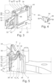
- the latter In the region of the protective walls 42, 43, the latter have two groove-like slots 51, 52 which are oriented towards one another and into which a blocking element 54 that consists of metal, in particular of steel, is insertable or introducible in a linear manner in an introduction direction 56.
- the blocking element 54 illustrated on its own in Figure 4 , has, on each side facing the inner faces 46, 47 of the protective walls 42, 43, for example three barb-like protrusions 58, which come into contact with the protective walls 42, 43 upon insertion of the blocking element 54 between the protective walls 42, 43, and lock together with the protective walls 42, 43 by plastic deformation of the material of the protective walls 42, 43, such that the blocking element 54 is held in a nominal position without further securing elements.
- This nominal position is defined by the depth of the slots 51, 52 in the protective walls 42, 43 in combination with portions 59, 60 of the blocking element 54 that project laterally away from the blocking element 54.
- the portions 59, 60 come into abutting contact in the nominal position with the bottom of the slots 51, 52.
- Figure 5 shows the spring element 35 in three positions X, Y and Z.
- the blocking element 54 is not illustrated in the receptacle 40 or the slots 51, 52 for reasons of simplification.
- the position X indicates a position of the spring element 35 in which the blocking element 54 is not assembled. In this state, the spring element 35 is relaxed, or without spring preload, and the contact portion 34 is thus at its greatest distance A 1 from the cover bottom 38. In the position of the spring element 35 that is indicated by Y, the distance A 2 of the contact portion 34 from the cover bottom 38 is less than the distance A 1 .
- the position Y of the spring element 35 indicates the position of the spring element 35 in which the blocking element 54 is located in its nominal position and in which the spring element 35 is partially preloaded.
- the gearbox cover 22 has not yet been connected to the first housing part 18 of the gearbox housing 16.
- the gearbox cover 22 is supplied for example to the assembly line for the wiper motor 10.
- the contact portion 34 of the spring element 35 comes into abutting contact with the element 30 or the track 32.
- the spring element 35 is pushed into the position Z, in which the distance A 3 from the cover bottom 38 is even smaller than the distance A 2 .
- the spring preload of the spring element 35 in order to generate a contact force F ( Figure 2 ) on the track 32 and the element 30, is greater than in the position Y of the spring element 35.
- a gap 62 (only indicated in Figure 3 ) is formed between the spring element 35 and the facing side of the blocking element 54.
- the blocking element 54 has no function, wherein the spring element 35, as a result of the gap 62, can move freely to a certain extent, i.e. the distance A can change on account of the tolerance compensation between the components or on account of a different level of the element 30 and of the track 32.
Landscapes
- Engineering & Computer Science (AREA)
- Mechanical Engineering (AREA)
- Power Engineering (AREA)
- Motor Or Generator Frames (AREA)
- Connection Of Motors, Electrical Generators, Mechanical Devices, And The Like (AREA)
Description
- The invention relates to a wiper motor having the features in the preamble of Claim 1, as is used for cleaning a vehicle window by means of at least one wiper blade. Furthermore, the invention relates to a method for producing a wiper motor according to the invention.
- A wiper motor having the features in the preamble of Claim 1 is known from the Applicant's
DE 10 2011 051 090 A1 - The wiper motor according to the invention having the features of Claim 1 has the advantage that the housing element with the spring element arranged thereon is mechanically more robust, making it possible for example, in particular during transport and handling, to store the housing element more easily in the transport containers, that is to say without additional receptacles, or similar elements, protecting the spring elements. Such handling or such transport reduces costs, wherein, at the same time, damage to and deformation of the spring element are avoided sufficiently reliably by a protected arrangement of the spring element, and so the functionality of the wiper motor after assembly is ensured.
- According to the invention, in this regard, the teaching of Claim 1 proposes that a blocking element be provided on the housing element, the housing element being a gearbox cover for closing a gearbox housing of the wiper motor, a counterpart element for cooperating with the spring element being arranged in the region of a gearwheel, such that the blocking element holds the spring element in an elastically deformed position in which the deformation of the spring element is less than in the working position of the spring element with the wiper motor assembled.
- The partially deformed (intermediate) position of the spring element before it is assembled on the gearbox housing results in a smaller overall height of the gearbox cover and thus not only results in a more compact arrangement in a transport container, but also the probability of contact with other components or gearbox covers, and thus a potential deformation risk or damage to the spring element, is reduced.
- Advantageous developments of the wiper motor according to the invention are presented in the dependent claims.
- In particular, as a result of the blocking element, a contact portion of the spring element in the first, relaxed position is at a distance from a cover bottom of the gearbox cover that is greater than a distance of the contact portion of the spring element in the third position, in which the blocking element acts on the spring element, and a distance of the contact portion of the spring element in the second position (with the wiper motor assembled) from the cover bottom is less than the distance in the third position of the contact portion of the spring element. Such an arrangement has the effect that a reduced distance and, as seen overall, a gearbox cover having a lower height in the region of the spring element before assembly is achieved.
- It is very particularly preferred when the spring element in the second and third positions is arranged regionally in a receptacle of the housing element. This means that, apart from the region of the spring element in the contact portion, the spring element is arranged within a receptacle or opening mechanically protecting the spring element. As a result, only the immediate contact portion of the spring element is arranged in a manner not protected from mechanical influences.
- In a development of the last proposal, the receptacle has protective walls, which are arranged at a small distance from the spring element, and the protective walls are connected integrally to the housing element. Since such a housing element is usually in the form of an injection-moulded plastics part in practice, the formation of such a receptacle, apart from a slightly smaller amount of material used, does not require increased manufacturing complexity. Rather, during manufacture or during the injection-moulding of the housing cover, the receptacle is integrally formed on the housing cover.
- In order to ensure the functionality or the abutting contact of the spring element with the corresponding counterpart surface of the gearwheel, provision is preferably made for a contact portion of the spring element to project beyond an end side of the protective walls in the three positions of the spring element.
- As already mentioned above, provision is furthermore preferably made for the housing element to consist of plastic and to be in the form of an injection-moulded part, and for the electrical line connected to the spring element to be encapsulated regionally with the material of the housing element.
- In order to allow the blocking element to be assembled easily as far as possible without tools, provision is made for the blocking element to be connected to the housing element by means of a force- and/or form-fitting connection.
- In a development of this proposal, the blocking element consists of a harder material than the housing element, in particular of steel, and the blocking element has barb-like elements that plastically deform the material of the housing element in the installed position of the blocking element in the housing element and as a result interlock with the material of the housing element.
- Such a blocking element is formed preferably in a plate-like manner and is guided in a linearly movable manner in groove-like slots in the housing element.
- In order to ensure the required nominal position of the blocking element in the housing element without complicated auxiliary devices, it is furthermore advantageous when the blocking element has at least one stop region for limiting the movement of the blocking element in the housing element in an insertion direction.
- Furthermore, the invention also relates to a method for producing a wiper motor as described thus far, wherein the method has at least the following steps: First of all, the housing element or the gearbox cover with the electrical line (and spring element) fastened thereto is produced. Next, the blocking element is fastened to the housing element, wherein the spring element is moved from the first (unloaded) position into the third, partially preloaded position. Finally, the housing element is assembled on the wiper motor, wherein a counterpart element, cooperating with a contact portion of the spring element, on the housing element moves the spring element from the third position into the second.
- Further advantages, features and details of the invention will become apparent from the following description of preferred exemplary embodiments of the invention and with reference to the drawings.
-
- Figure 1
- shows a wiper motor in a simplified longitudinal section,
- Figure 2
- shows a perspective illustration in partial section of a spring element, cooperating with a gearwheel, in a gearbox housing without a gearbox cover being illustrated,
- Figure 3
- shows a perspective illustration of a partial region of the gearbox cover with the spring element arranged in a protected manner in a receptacle of the gearbox cover,
- Figure 4
- shows a perspective illustration of a blocking element used in the arrangement according to
Figure 3 , and - Figure 5
- shows a perspective illustration for exemplifying different positions of the spring element in the gearbox cover.
- Identical elements or elements having an identical function are provided with the same reference numbers in the figures.
- The
wiper motor 10 illustrated in a highly simplified manner inFigure 1 serves for at least indirectly driving a wiper arm or windscreen wiper (not illustrated). To this end, thewiper motor 10 has anelectric motor 12, thehousing 14 of which is flange-mounted on agearbox housing 16. Thegearbox housing 16 consists of at least two components, a pot-likefirst housing element 18, which is connected to a second housing element 20 in the form of agearbox cover 22 via screw connections or via latching connections and closed off. - Within the
gearbox housing 16, agearwheel 24 is mounted in a rotatable manner on an axis ofrotation 25, saidgearwheel 24 being coupled in particular to anoutput shaft 26 that projects out of thegearbox housing 16 and serves to actuate the wiper arm or windscreen wiper. - The
gearwheel 24 has on its outer circumference atoothing 27, which cooperates with a worm toothing (not shown) on anoutput shaft 28 of theelectric motor 12. During operation of thewiper motor 10, or when the windscreen wiper is actuated, it is essential to detect the precise angular position of the wiper arm or windscreen wiper. This takes place via identification of the rotation-angle position of thegearwheel 24. To this end, thegearwheel 24 has at least one electrically conductive element, preferably in the form of a metal,flat element 30. Theelement 30 transitions, as seen in the circumferential direction about the axis ofrotation 25, into atrack 32 that consists of the plastic of thegearwheel 24 and is arranged concentrically with the axis ofrotation 25. - With the
gearbox housing 16 assembled, thetrack 32 or theelement 30 is arranged as counterpart element in abutting contact with acontact portion 34 of aspring element 35. Thespring element 35 is configured in particular in the form of a stamped/bent part and consists of a sheet-metal blank. On that side of thespring element 35 that faces away from thecontact portion 34, the end portion 36 (discernible inFigure 2 ) is arranged for example in electrically conductive contact with a socket-like receptacle in a further stamped/bent part 39, which, together with thespring element 35, forms anelectrical line 37. The stamped/bent part 39 is brought into contact with theend portion 36 during the assembly of thewiper motor 10. Thegearbox cover 22 is in the form of an injection-moulded plastics part and regionally surrounds thespring element 35 by encapsulation, wherein thespring element 35 and theend portion 36 project out of thegearbox cover 22 and are free of the material of thegearbox cover 22. - In accordance with the illustration in
Figures 3 to 5 , thespring element 35 projects with itscontact portion 34 away from acover bottom 38 of thegearbox cover 22, out of which it projects or is arranged at a distance A therefrom. It is essential here that at least a partial region of the portion of thespring element 35 that projects away from thecover bottom 38 is arranged in a protected manner. To this end, thegearbox cover 22, as is discernible in particular from the illustration inFigures 3 and 5 , has areceptacle 40 for regionally receiving thespring element 35. Thereceptacle 40 is formed fromprotective walls 42 to 44, which project perpendicularly away from the cover bottom 38 and are integrally formed on thegearbox cover 22. In particular, thereceptacle 40 is configured in a slot-like manner, such that the mutually facinginner faces protective walls spring element 35 that face them. Furthermore, thecontact portion 34 of thespring element 35 projects beyond the end faces 48, facing away from the cover bottom 38, of theprotective walls 42 to 44. - In the region of the
protective walls like slots element 54 that consists of metal, in particular of steel, is insertable or introducible in a linear manner in anintroduction direction 56. The blockingelement 54, illustrated on its own inFigure 4 , has, on each side facing the inner faces 46, 47 of theprotective walls like protrusions 58, which come into contact with theprotective walls element 54 between theprotective walls protective walls protective walls element 54 is held in a nominal position without further securing elements. This nominal position is defined by the depth of theslots protective walls portions element 54 that project laterally away from the blockingelement 54. When the blockingelement 54 is introduced between theslots portions slots -
Figure 5 shows thespring element 35 in three positions X, Y and Z. In this case, the blockingelement 54 is not illustrated in thereceptacle 40 or theslots spring element 35 in which the blockingelement 54 is not assembled. In this state, thespring element 35 is relaxed, or without spring preload, and thecontact portion 34 is thus at its greatest distance A1 from thecover bottom 38. In the position of thespring element 35 that is indicated by Y, the distance A2 of thecontact portion 34 from the cover bottom 38 is less than the distance A1. The position Y of thespring element 35 indicates the position of thespring element 35 in which the blockingelement 54 is located in its nominal position and in which thespring element 35 is partially preloaded. In this case, however, thegearbox cover 22 has not yet been connected to thefirst housing part 18 of thegearbox housing 16. In this state, thegearbox cover 22 is supplied for example to the assembly line for thewiper motor 10. During the assembly of thewiper motor 10, in particular during the connection of thegearbox cover 22 to thefirst housing part 18, thecontact portion 34 of thespring element 35 comes into abutting contact with theelement 30 or thetrack 32. As a result, thespring element 35 is pushed into the position Z, in which the distance A3 from the cover bottom 38 is even smaller than the distance A2. In the position Z, the spring preload of thespring element 35, in order to generate a contact force F (Figure 2 ) on thetrack 32 and theelement 30, is greater than in the position Y of thespring element 35. Furthermore, in the position Z of thespring element 35, a gap 62 (only indicated inFigure 3 ) is formed between thespring element 35 and the facing side of the blockingelement 54. In the position Z of thespring element 35, this position being necessary in order for it to be possible to operate thewiper motor 10 properly, the blockingelement 54 has no function, wherein thespring element 35, as a result of thegap 62, can move freely to a certain extent, i.e. the distance A can change on account of the tolerance compensation between the components or on account of a different level of theelement 30 and of thetrack 32. - The
wiper motor 10 described thus far can be altered or modified in a wide variety of ways without departing from the concept of the invention. -
- 10
- Wiper motor
- 12
- Electric motor
- 14
- Housing
- 16
- Gearbox housing
- 18
- Housing element
- 20
- Housing element
- 22
- Gearbox cover
- 24
- Gearwheel
- 25
- Axis of rotation
- 26
- Output shaft
- 27
- Toothing
- 28
- Output shaft
- 30
- Element
- 32
- Track
- 34
- Contact portion
- 35
- Spring element
- 36
- End portion
- 37
- Line
- 38
- Cover bottom
- 39
- Stamped/bent part
- 40
- Receptacle
- 42
- Protective wall
- 43
- Protective wall
- 44
- Protective wall
- 46
- Inner face
- 47
- Inner face
- 48
- End side
- 51
- Slot
- 52
- Slot
- 54
- Blocking element
- 56
- Introduction direction
- 58
- Protrusion
- 59
- Portion
- 60
- Portion
- 62
- Gap
- A
- Distance
- A1
- Distance
- A2
- Distance
- A3
- Distance
- X
- Position
- Y
- Position
- Z
- Position
- F
- Contact force
Claims (12)
- Wiper motor (10) having a housing element (20) connected to an electrical line (37) that has an elastically deformable spring element (35) in an end region projecting out of the housing element (20), wherein the spring element (35), in order to form an electrically conductive connection with a counterpart element (30, 32), is movable, with respect to a first, relaxed position (X) of the spring element (35), into a second, elastically deformed position (Z) generating a contact force (F) on the counterpart element (30, 32),whereinthe housing element (20) is a gearbox cover (22) for closing a gearbox housing (16) of the wiper motor (10), the counterpart element (30, 32) for cooperating with the spring element (35) being arranged in the region of a gearwheel (24), characterized in that a blocking element (54) is fastened on the housing element (20) which holds the spring element (35) in a third, elastically deformed position (Y) in which the deformation of the spring element (35) is less than in the second position (Z) of the spring element (35).
- Wiper motor according to Claim 1,
characterized
in that a contact portion (34) of the spring element (35) in the first position (X) is at a distance (A1) from a cover bottom (38) that is greater than a distance (A2) of the contact portion (34) of the spring element (35) in the third position (Y), and in that a distance (A3) of the contact portion (34) of the spring element (35) in the second position (Z) from the cover bottom (38) is less than the distance (A2) in the third position (Y) of the contact portion (34) of the spring element (35). - Wiper motor according to Claim 1 or 2,
characterized
in that the spring element (35) in the second position (Z) and in the third position (Y) is arranged regionally in a receptacle (40) of the housing element (20). - Wiper motor according to Claim 3,
characterized
in that the receptacle (40) has protective walls (42 to 44), which are arranged at a small distance from the spring element (35), and in that the protective walls (42 to 44) are connected integrally to the housing element (20). - Wiper motor according to Claim 4,
characterized
in that the spring element (35) projects regionally beyond an end side (48) of the protective walls (42 to 44) in the three positions (X, Y, Z). - Wiper motor according to any one of Claims 1 to 5,
characterized
in that the housing element (20) consists of plastic and is in the form of an injection-moulded part, and in that the electrical line (37) is encapsulated regionally with the material of the housing element (20). - Wiper motor according to any one of Claims 1 to 6,
characterized
in that the blocking element (54) is connected to the housing element (20) by means of a force- and/or form-fitting connection. - Wiper motor according to Claim 7,
characterized
in that the blocking element (54) consists of a harder material than the housing element (20), in particular of steel, and in that the blocking element (54) has barb-like protrusions (58) that plastically deform the material of the housing element (20) in the installed position of the blocking element (54) in the housing element (20). - Wiper motor according to Claim 8,
characterized
in that the blocking element (54) is formed in a plate-like manner and is guided in a linearly movable manner in groove-like slots (51, 52) in the housing element (20). - Wiper motor according to Claim 8 or 9,
characterized
in that the blocking element (54) has at least one portion (59, 60) for limiting the movement of the blocking element (54) in the slots (51, 52) of the housing element (20) in an introduction direction (56). - Wiper motor according to any one of Claims 1 to 10,
characterized
in that a gap (62) is formed between the spring element (35) and the blocking element (54) in the second position (Z) of the spring element (35). - Method for producing a wiper motor (10) configured according to one of Claims 1 to 11, comprising at least the following steps:- producing the housing element (20) with the electrical line (37) fastened thereto,- fastening the blocking element (54) to the housing element (20), wherein the spring element (35) is moved from the first position (X) into the third position (Y),- assembling the housing element (20) on the wiper motor (10), wherein a counterpart element (30, 32) cooperating with a contact portion (34) of the spring element (35) moves the spring element (35) from the third position (Y) into the second position (Z).
Applications Claiming Priority (2)
| Application Number | Priority Date | Filing Date | Title |
|---|---|---|---|
| DE102019117843.6A DE102019117843A1 (en) | 2019-07-02 | 2019-07-02 | Wiper motor and process for its manufacture |
| PCT/EP2020/068203 WO2021001299A1 (en) | 2019-07-02 | 2020-06-29 | Wiper motor and method for the production thereof |
Publications (2)
| Publication Number | Publication Date |
|---|---|
| EP3994038A1 EP3994038A1 (en) | 2022-05-11 |
| EP3994038B1 true EP3994038B1 (en) | 2024-08-21 |
Family
ID=71523118
Family Applications (1)
| Application Number | Title | Priority Date | Filing Date |
|---|---|---|---|
| EP20737111.3A Active EP3994038B1 (en) | 2019-07-02 | 2020-06-29 | Wiper motor and method for the production thereof |
Country Status (7)
| Country | Link |
|---|---|
| US (1) | US12054125B2 (en) |
| EP (1) | EP3994038B1 (en) |
| JP (1) | JP7534341B2 (en) |
| CN (1) | CN114051469B (en) |
| BR (1) | BR112021024134A2 (en) |
| DE (1) | DE102019117843A1 (en) |
| WO (1) | WO2021001299A1 (en) |
Families Citing this family (2)
| Publication number | Priority date | Publication date | Assignee | Title |
|---|---|---|---|---|
| DE102022110700A1 (en) | 2022-05-02 | 2023-11-02 | Valeo Systèmes d'Éssuyage SAS | Gearbox and windshield wiper motor with a gearbox |
| EP4300788A1 (en) * | 2022-06-28 | 2024-01-03 | Valeo Systèmes d'Essuyage | Electrical component for a windscreen wiper motor |
Citations (1)
| Publication number | Priority date | Publication date | Assignee | Title |
|---|---|---|---|---|
| FR2981030A1 (en) * | 2011-10-07 | 2013-04-12 | Valeo Systemes Dessuyage | Support for controlling drive system of wiper in car, has detection unit comprising conductive contact blade, where part of contact blade is received in housing that is attached with mounting plate |
Family Cites Families (22)
| Publication number | Priority date | Publication date | Assignee | Title |
|---|---|---|---|---|
| DE3220191A1 (en) * | 1982-05-28 | 1983-12-01 | SWF-Spezialfabrik für Autozubehör Gustav Rau GmbH, 7120 Bietigheim-Bissingen | ELECTRIC DRIVE UNIT, IN PARTICULAR FOR WINDOW WIPERS OF A MOTOR VEHICLE |
| DE3324634A1 (en) * | 1983-07-08 | 1985-01-24 | Daimler-Benz Ag, 7000 Stuttgart | WINDOW WIPER, ESPECIALLY FOR MOTOR VEHICLES |
| JPH0631623Y2 (en) * | 1985-07-29 | 1994-08-22 | 株式会社三ツ葉電機製作所 | Relay insulator |
| DE3812996A1 (en) * | 1988-04-19 | 1989-11-09 | Swf Auto Electric Gmbh | ELECTRIC MOTOR, ESPECIALLY WIPER MOTOR FOR DRIVING A WINDOW WIPER SYSTEM IN A MOTOR VEHICLE |
| JPH09118201A (en) * | 1995-10-24 | 1997-05-06 | Jidosha Denki Kogyo Co Ltd | Wiper motor |
| DE10340940A1 (en) * | 2003-09-05 | 2005-03-31 | Robert Bosch Gmbh | Electric machine with easy-to-position brush holder and mounting method for electrical machine |
| FR2865981B1 (en) * | 2004-02-06 | 2006-04-21 | Valeo Systemes Dessuyage | MOTO-REDUCER, IN PARTICULAR FOR AUTOMOTIVE VEHICLE WIPER MECHANISM |
| DE102007042694A1 (en) * | 2007-09-07 | 2009-03-12 | Magna Electronics Europe Gmbh & Co.Kg | sensor module |
| DE102009014312A1 (en) * | 2009-03-25 | 2010-09-30 | Valeo Systèmes d'Essuyage | Electromotive auxiliary drive, in particular wiper drive |
| DE102009029469A1 (en) * | 2009-09-15 | 2011-03-24 | Robert Bosch Gmbh | Wiper blade with an adapter unit for attachment to a wiper arm |
| DE102009043322A1 (en) * | 2009-09-28 | 2011-03-31 | Valeo Systèmes d'Essuyage | Electromotive auxiliary drive |
| DE102010062236A1 (en) * | 2010-12-01 | 2012-06-06 | Robert Bosch Gmbh | wiper drive |
| DE102011051090A1 (en) * | 2011-06-15 | 2012-12-20 | Valeo Systèmes d'Essuyage | Drive device and windshield wiper device with drive device |
| DE102012102811A1 (en) * | 2012-03-30 | 2013-10-02 | Valeo Wischersysteme Gmbh | Windscreen wiper motor and suppressor assembly for a windscreen wiper motor |
| DE102012223894A1 (en) * | 2012-12-20 | 2014-06-26 | Robert Bosch Gmbh | Drive device with position-dependent switching device for signal evaluation to a falling signal |
| DE102014212133A1 (en) * | 2014-06-25 | 2015-12-31 | Robert Bosch Gmbh | drive unit |
| FR3048395B1 (en) | 2016-03-07 | 2019-06-21 | Valeo Systemes D'essuyage | WHEEL FOR A VEHICLE ICE WIPER DRIVE SYSTEM |
| DE102016124039A1 (en) * | 2016-12-12 | 2018-06-14 | Valeo Systèmes d'Essuyage | Wiper motor and method of manufacturing a wiper motor |
| FR3061467B1 (en) | 2017-01-02 | 2019-05-24 | Valeo Systemes D'essuyage | FRONT WIPER DEVICE FOR MOTOR VEHICLE AND METHOD OF MOUNTING |
| DE102017110470A1 (en) * | 2017-05-15 | 2018-11-15 | Valeo Systèmes d'Essuyage | Carbon holder plate for an electric motor, windscreen wiper motor and method for mounting a windscreen wiper motor |
| DE102017113632B4 (en) * | 2017-06-21 | 2021-06-24 | Dr. Ing. H.C. F. Porsche Aktiengesellschaft | windshield wipers |
| DE102020209500A1 (en) * | 2020-07-28 | 2022-02-03 | Brose Fahrzeugteile Se & Co. Kommanditgesellschaft, Bamberg | Driving device with a brushless electric motor |
-
2019
- 2019-07-02 DE DE102019117843.6A patent/DE102019117843A1/en active Pending
-
2020
- 2020-06-29 WO PCT/EP2020/068203 patent/WO2021001299A1/en not_active Ceased
- 2020-06-29 EP EP20737111.3A patent/EP3994038B1/en active Active
- 2020-06-29 BR BR112021024134A patent/BR112021024134A2/en not_active Application Discontinuation
- 2020-06-29 US US17/621,170 patent/US12054125B2/en active Active
- 2020-06-29 JP JP2021578051A patent/JP7534341B2/en active Active
- 2020-06-29 CN CN202080047921.7A patent/CN114051469B/en active Active
Patent Citations (1)
| Publication number | Priority date | Publication date | Assignee | Title |
|---|---|---|---|---|
| FR2981030A1 (en) * | 2011-10-07 | 2013-04-12 | Valeo Systemes Dessuyage | Support for controlling drive system of wiper in car, has detection unit comprising conductive contact blade, where part of contact blade is received in housing that is attached with mounting plate |
Also Published As
| Publication number | Publication date |
|---|---|
| EP3994038A1 (en) | 2022-05-11 |
| US20220363222A1 (en) | 2022-11-17 |
| CN114051469A (en) | 2022-02-15 |
| JP2022539219A (en) | 2022-09-07 |
| DE102019117843A1 (en) | 2021-01-07 |
| CN114051469B (en) | 2024-01-05 |
| BR112021024134A2 (en) | 2022-01-11 |
| JP7534341B2 (en) | 2024-08-14 |
| US12054125B2 (en) | 2024-08-06 |
| WO2021001299A1 (en) | 2021-01-07 |
Similar Documents
| Publication | Publication Date | Title |
|---|---|---|
| EP3994038B1 (en) | Wiper motor and method for the production thereof | |
| US12354813B2 (en) | Actuation device for mounting on a vehicle part, vehicle and method for actuation for triggering a vehicle function | |
| KR100679881B1 (en) | Electric motors, especially wiper motors for car glass washing | |
| US20070207644A1 (en) | Fixing member for electric conductors, electric conductor structure component and method for producing such a component | |
| US7806018B2 (en) | Gear mechanism unit for a motor vehicle actuating drive | |
| KR102507727B1 (en) | drive for vehicles | |
| US10658782B2 (en) | Stop spring for a contact device, electrical contact de-vice assembly as well as electrical connector | |
| CN103891107B (en) | Servo-driver | |
| US11088590B2 (en) | Connection unit for a wiper motor and wiper motor | |
| US6045411A (en) | Switching and controlling electrical device for a motor vehicle | |
| CN109891721B (en) | electric motor | |
| US6600118B2 (en) | Actuating system including a module element for assembly in a panel | |
| EP2774820B1 (en) | Housing for a windscreen wiper motor, method for producing a housing for a windscreen wiper motor, and windscreen wiper motor | |
| US8766120B2 (en) | Microswitch | |
| KR102767007B1 (en) | Control unit with contact concept for ground connection | |
| CN102570230B (en) | Brushgear in the reverser assembly of motor | |
| CN111697746B (en) | Adapter element, transmission drive and mould for producing an adapter element | |
| EP3844848B1 (en) | Windscreen wiper motor and method of assembling the windscreen wiper motor | |
| KR101949475B1 (en) | A actuator for a vechicle | |
| CN114128107B (en) | Electric motor, in particular for adjusting movable parts in a motor vehicle | |
| JP4926562B2 (en) | Manufacturing method of sheet metal molded product | |
| KR20110009662A (en) | Wiper motors, especially boxes for rear wiper motors and wiper motors | |
| WO2022157058A1 (en) | Wiper motor, method for assembling a wiper motor, and assembly tool | |
| JP2025510328A (en) | Automotive Electrical Component Assembly | |
| JPH0429579B2 (en) |
Legal Events
| Date | Code | Title | Description |
|---|---|---|---|
| STAA | Information on the status of an ep patent application or granted ep patent |
Free format text: STATUS: UNKNOWN |
|
| STAA | Information on the status of an ep patent application or granted ep patent |
Free format text: STATUS: THE INTERNATIONAL PUBLICATION HAS BEEN MADE |
|
| PUAI | Public reference made under article 153(3) epc to a published international application that has entered the european phase |
Free format text: ORIGINAL CODE: 0009012 |
|
| STAA | Information on the status of an ep patent application or granted ep patent |
Free format text: STATUS: REQUEST FOR EXAMINATION WAS MADE |
|
| 17P | Request for examination filed |
Effective date: 20211202 |
|
| AK | Designated contracting states |
Kind code of ref document: A1 Designated state(s): AL AT BE BG CH CY CZ DE DK EE ES FI FR GB GR HR HU IE IS IT LI LT LU LV MC MK MT NL NO PL PT RO RS SE SI SK SM TR |
|
| DAV | Request for validation of the european patent (deleted) | ||
| DAX | Request for extension of the european patent (deleted) | ||
| STAA | Information on the status of an ep patent application or granted ep patent |
Free format text: STATUS: EXAMINATION IS IN PROGRESS |
|
| P01 | Opt-out of the competence of the unified patent court (upc) registered |
Effective date: 20230528 |
|
| 17Q | First examination report despatched |
Effective date: 20230711 |
|
| GRAP | Despatch of communication of intention to grant a patent |
Free format text: ORIGINAL CODE: EPIDOSNIGR1 |
|
| STAA | Information on the status of an ep patent application or granted ep patent |
Free format text: STATUS: GRANT OF PATENT IS INTENDED |
|
| INTG | Intention to grant announced |
Effective date: 20240507 |
|
| GRAS | Grant fee paid |
Free format text: ORIGINAL CODE: EPIDOSNIGR3 |
|
| GRAA | (expected) grant |
Free format text: ORIGINAL CODE: 0009210 |
|
| STAA | Information on the status of an ep patent application or granted ep patent |
Free format text: STATUS: THE PATENT HAS BEEN GRANTED |
|
| AK | Designated contracting states |
Kind code of ref document: B1 Designated state(s): AL AT BE BG CH CY CZ DE DK EE ES FI FR GB GR HR HU IE IS IT LI LT LU LV MC MK MT NL NO PL PT RO RS SE SI SK SM TR |
|
| REG | Reference to a national code |
Ref country code: GB Ref legal event code: FG4D |
|
| REG | Reference to a national code |
Ref country code: CH Ref legal event code: EP |
|
| REG | Reference to a national code |
Ref country code: IE Ref legal event code: FG4D |
|
| REG | Reference to a national code |
Ref country code: DE Ref legal event code: R096 Ref document number: 602020036216 Country of ref document: DE |
|
| REG | Reference to a national code |
Ref country code: LT Ref legal event code: MG9D |
|
| REG | Reference to a national code |
Ref country code: NL Ref legal event code: MP Effective date: 20240821 |
|
| PG25 | Lapsed in a contracting state [announced via postgrant information from national office to epo] |
Ref country code: NO Free format text: LAPSE BECAUSE OF FAILURE TO SUBMIT A TRANSLATION OF THE DESCRIPTION OR TO PAY THE FEE WITHIN THE PRESCRIBED TIME-LIMIT Effective date: 20241121 |
|
| REG | Reference to a national code |
Ref country code: AT Ref legal event code: MK05 Ref document number: 1715231 Country of ref document: AT Kind code of ref document: T Effective date: 20240821 |
|
| PG25 | Lapsed in a contracting state [announced via postgrant information from national office to epo] |
Ref country code: FI Free format text: LAPSE BECAUSE OF FAILURE TO SUBMIT A TRANSLATION OF THE DESCRIPTION OR TO PAY THE FEE WITHIN THE PRESCRIBED TIME-LIMIT Effective date: 20240821 Ref country code: NL Free format text: LAPSE BECAUSE OF FAILURE TO SUBMIT A TRANSLATION OF THE DESCRIPTION OR TO PAY THE FEE WITHIN THE PRESCRIBED TIME-LIMIT Effective date: 20240821 Ref country code: PT Free format text: LAPSE BECAUSE OF FAILURE TO SUBMIT A TRANSLATION OF THE DESCRIPTION OR TO PAY THE FEE WITHIN THE PRESCRIBED TIME-LIMIT Effective date: 20241223 Ref country code: GR Free format text: LAPSE BECAUSE OF FAILURE TO SUBMIT A TRANSLATION OF THE DESCRIPTION OR TO PAY THE FEE WITHIN THE PRESCRIBED TIME-LIMIT Effective date: 20241122 Ref country code: PL Free format text: LAPSE BECAUSE OF FAILURE TO SUBMIT A TRANSLATION OF THE DESCRIPTION OR TO PAY THE FEE WITHIN THE PRESCRIBED TIME-LIMIT Effective date: 20240821 |
|
| PG25 | Lapsed in a contracting state [announced via postgrant information from national office to epo] |
Ref country code: BG Free format text: LAPSE BECAUSE OF FAILURE TO SUBMIT A TRANSLATION OF THE DESCRIPTION OR TO PAY THE FEE WITHIN THE PRESCRIBED TIME-LIMIT Effective date: 20240821 |
|
| PG25 | Lapsed in a contracting state [announced via postgrant information from national office to epo] |
Ref country code: LV Free format text: LAPSE BECAUSE OF FAILURE TO SUBMIT A TRANSLATION OF THE DESCRIPTION OR TO PAY THE FEE WITHIN THE PRESCRIBED TIME-LIMIT Effective date: 20240821 |
|
| PG25 | Lapsed in a contracting state [announced via postgrant information from national office to epo] |
Ref country code: AT Free format text: LAPSE BECAUSE OF FAILURE TO SUBMIT A TRANSLATION OF THE DESCRIPTION OR TO PAY THE FEE WITHIN THE PRESCRIBED TIME-LIMIT Effective date: 20240821 Ref country code: IS Free format text: LAPSE BECAUSE OF FAILURE TO SUBMIT A TRANSLATION OF THE DESCRIPTION OR TO PAY THE FEE WITHIN THE PRESCRIBED TIME-LIMIT Effective date: 20241221 |
|
| PG25 | Lapsed in a contracting state [announced via postgrant information from national office to epo] |
Ref country code: HR Free format text: LAPSE BECAUSE OF FAILURE TO SUBMIT A TRANSLATION OF THE DESCRIPTION OR TO PAY THE FEE WITHIN THE PRESCRIBED TIME-LIMIT Effective date: 20240821 |
|
| PG25 | Lapsed in a contracting state [announced via postgrant information from national office to epo] |
Ref country code: ES Free format text: LAPSE BECAUSE OF FAILURE TO SUBMIT A TRANSLATION OF THE DESCRIPTION OR TO PAY THE FEE WITHIN THE PRESCRIBED TIME-LIMIT Effective date: 20240821 Ref country code: RS Free format text: LAPSE BECAUSE OF FAILURE TO SUBMIT A TRANSLATION OF THE DESCRIPTION OR TO PAY THE FEE WITHIN THE PRESCRIBED TIME-LIMIT Effective date: 20241121 |
|
| PG25 | Lapsed in a contracting state [announced via postgrant information from national office to epo] |
Ref country code: RS Free format text: LAPSE BECAUSE OF FAILURE TO SUBMIT A TRANSLATION OF THE DESCRIPTION OR TO PAY THE FEE WITHIN THE PRESCRIBED TIME-LIMIT Effective date: 20241121 Ref country code: PT Free format text: LAPSE BECAUSE OF FAILURE TO SUBMIT A TRANSLATION OF THE DESCRIPTION OR TO PAY THE FEE WITHIN THE PRESCRIBED TIME-LIMIT Effective date: 20241223 Ref country code: PL Free format text: LAPSE BECAUSE OF FAILURE TO SUBMIT A TRANSLATION OF THE DESCRIPTION OR TO PAY THE FEE WITHIN THE PRESCRIBED TIME-LIMIT Effective date: 20240821 Ref country code: NO Free format text: LAPSE BECAUSE OF FAILURE TO SUBMIT A TRANSLATION OF THE DESCRIPTION OR TO PAY THE FEE WITHIN THE PRESCRIBED TIME-LIMIT Effective date: 20241121 Ref country code: NL Free format text: LAPSE BECAUSE OF FAILURE TO SUBMIT A TRANSLATION OF THE DESCRIPTION OR TO PAY THE FEE WITHIN THE PRESCRIBED TIME-LIMIT Effective date: 20240821 Ref country code: LV Free format text: LAPSE BECAUSE OF FAILURE TO SUBMIT A TRANSLATION OF THE DESCRIPTION OR TO PAY THE FEE WITHIN THE PRESCRIBED TIME-LIMIT Effective date: 20240821 Ref country code: IS Free format text: LAPSE BECAUSE OF FAILURE TO SUBMIT A TRANSLATION OF THE DESCRIPTION OR TO PAY THE FEE WITHIN THE PRESCRIBED TIME-LIMIT Effective date: 20241221 Ref country code: HR Free format text: LAPSE BECAUSE OF FAILURE TO SUBMIT A TRANSLATION OF THE DESCRIPTION OR TO PAY THE FEE WITHIN THE PRESCRIBED TIME-LIMIT Effective date: 20240821 Ref country code: GR Free format text: LAPSE BECAUSE OF FAILURE TO SUBMIT A TRANSLATION OF THE DESCRIPTION OR TO PAY THE FEE WITHIN THE PRESCRIBED TIME-LIMIT Effective date: 20241122 Ref country code: FI Free format text: LAPSE BECAUSE OF FAILURE TO SUBMIT A TRANSLATION OF THE DESCRIPTION OR TO PAY THE FEE WITHIN THE PRESCRIBED TIME-LIMIT Effective date: 20240821 Ref country code: ES Free format text: LAPSE BECAUSE OF FAILURE TO SUBMIT A TRANSLATION OF THE DESCRIPTION OR TO PAY THE FEE WITHIN THE PRESCRIBED TIME-LIMIT Effective date: 20240821 Ref country code: BG Free format text: LAPSE BECAUSE OF FAILURE TO SUBMIT A TRANSLATION OF THE DESCRIPTION OR TO PAY THE FEE WITHIN THE PRESCRIBED TIME-LIMIT Effective date: 20240821 Ref country code: AT Free format text: LAPSE BECAUSE OF FAILURE TO SUBMIT A TRANSLATION OF THE DESCRIPTION OR TO PAY THE FEE WITHIN THE PRESCRIBED TIME-LIMIT Effective date: 20240821 |
|
| PG25 | Lapsed in a contracting state [announced via postgrant information from national office to epo] |
Ref country code: RO Free format text: LAPSE BECAUSE OF FAILURE TO SUBMIT A TRANSLATION OF THE DESCRIPTION OR TO PAY THE FEE WITHIN THE PRESCRIBED TIME-LIMIT Effective date: 20240821 Ref country code: SM Free format text: LAPSE BECAUSE OF FAILURE TO SUBMIT A TRANSLATION OF THE DESCRIPTION OR TO PAY THE FEE WITHIN THE PRESCRIBED TIME-LIMIT Effective date: 20240821 Ref country code: DK Free format text: LAPSE BECAUSE OF FAILURE TO SUBMIT A TRANSLATION OF THE DESCRIPTION OR TO PAY THE FEE WITHIN THE PRESCRIBED TIME-LIMIT Effective date: 20240821 |
|
| PG25 | Lapsed in a contracting state [announced via postgrant information from national office to epo] |
Ref country code: EE Free format text: LAPSE BECAUSE OF FAILURE TO SUBMIT A TRANSLATION OF THE DESCRIPTION OR TO PAY THE FEE WITHIN THE PRESCRIBED TIME-LIMIT Effective date: 20240821 |
|
| PG25 | Lapsed in a contracting state [announced via postgrant information from national office to epo] |
Ref country code: CZ Free format text: LAPSE BECAUSE OF FAILURE TO SUBMIT A TRANSLATION OF THE DESCRIPTION OR TO PAY THE FEE WITHIN THE PRESCRIBED TIME-LIMIT Effective date: 20240821 |
|
| PG25 | Lapsed in a contracting state [announced via postgrant information from national office to epo] |
Ref country code: SK Free format text: LAPSE BECAUSE OF FAILURE TO SUBMIT A TRANSLATION OF THE DESCRIPTION OR TO PAY THE FEE WITHIN THE PRESCRIBED TIME-LIMIT Effective date: 20240821 Ref country code: IT Free format text: LAPSE BECAUSE OF FAILURE TO SUBMIT A TRANSLATION OF THE DESCRIPTION OR TO PAY THE FEE WITHIN THE PRESCRIBED TIME-LIMIT Effective date: 20240821 |
|
| REG | Reference to a national code |
Ref country code: DE Ref legal event code: R097 Ref document number: 602020036216 Country of ref document: DE |
|
| PLBE | No opposition filed within time limit |
Free format text: ORIGINAL CODE: 0009261 |
|
| STAA | Information on the status of an ep patent application or granted ep patent |
Free format text: STATUS: NO OPPOSITION FILED WITHIN TIME LIMIT |
|
| PGFP | Annual fee paid to national office [announced via postgrant information from national office to epo] |
Ref country code: DE Payment date: 20250617 Year of fee payment: 6 |
|
| PGFP | Annual fee paid to national office [announced via postgrant information from national office to epo] |
Ref country code: FR Payment date: 20250630 Year of fee payment: 6 |
|
| 26N | No opposition filed |
Effective date: 20250522 |
|
| PG25 | Lapsed in a contracting state [announced via postgrant information from national office to epo] |
Ref country code: SE Free format text: LAPSE BECAUSE OF FAILURE TO SUBMIT A TRANSLATION OF THE DESCRIPTION OR TO PAY THE FEE WITHIN THE PRESCRIBED TIME-LIMIT Effective date: 20240821 |
|
| REG | Reference to a national code |
Ref country code: CH Ref legal event code: H13 Free format text: ST27 STATUS EVENT CODE: U-0-0-H10-H13 (AS PROVIDED BY THE NATIONAL OFFICE) Effective date: 20260127 |
|
| PG25 | Lapsed in a contracting state [announced via postgrant information from national office to epo] |
Ref country code: MC Free format text: LAPSE BECAUSE OF FAILURE TO SUBMIT A TRANSLATION OF THE DESCRIPTION OR TO PAY THE FEE WITHIN THE PRESCRIBED TIME-LIMIT Effective date: 20240821 |
|
| PG25 | Lapsed in a contracting state [announced via postgrant information from national office to epo] |
Ref country code: LU Free format text: LAPSE BECAUSE OF NON-PAYMENT OF DUE FEES Effective date: 20250629 |
|
| GBPC | Gb: european patent ceased through non-payment of renewal fee |
Effective date: 20250629 |
|
| REG | Reference to a national code |
Ref country code: BE Ref legal event code: MM Effective date: 20250630 |
|
| PG25 | Lapsed in a contracting state [announced via postgrant information from national office to epo] |
Ref country code: GB Free format text: LAPSE BECAUSE OF NON-PAYMENT OF DUE FEES Effective date: 20250629 |
|
| PG25 | Lapsed in a contracting state [announced via postgrant information from national office to epo] |
Ref country code: IE Free format text: LAPSE BECAUSE OF NON-PAYMENT OF DUE FEES Effective date: 20250629 |
|
| PG25 | Lapsed in a contracting state [announced via postgrant information from national office to epo] |
Ref country code: BE Free format text: LAPSE BECAUSE OF NON-PAYMENT OF DUE FEES Effective date: 20250630 |
|
| PG25 | Lapsed in a contracting state [announced via postgrant information from national office to epo] |
Ref country code: CH Free format text: LAPSE BECAUSE OF NON-PAYMENT OF DUE FEES Effective date: 20250630 |