EP3993506A1 - Wireless terminal, ran node, core network node, and method therefor - Google Patents
Wireless terminal, ran node, core network node, and method therefor Download PDFInfo
- Publication number
- EP3993506A1 EP3993506A1 EP20916628.9A EP20916628A EP3993506A1 EP 3993506 A1 EP3993506 A1 EP 3993506A1 EP 20916628 A EP20916628 A EP 20916628A EP 3993506 A1 EP3993506 A1 EP 3993506A1
- Authority
- EP
- European Patent Office
- Prior art keywords
- radio terminal
- authentication
- nas
- message
- bits
- Prior art date
- Legal status (The legal status is an assumption and is not a legal conclusion. Google has not performed a legal analysis and makes no representation as to the accuracy of the status listed.)
- Withdrawn
Links
- 238000000034 method Methods 0.000 title claims abstract description 91
- 230000004044 response Effects 0.000 claims abstract description 80
- 230000015654 memory Effects 0.000 claims description 64
- CSRZQMIRAZTJOY-UHFFFAOYSA-N trimethylsilyl iodide Substances C[Si](C)(C)I CSRZQMIRAZTJOY-UHFFFAOYSA-N 0.000 claims description 24
- 230000006870 function Effects 0.000 claims description 17
- 238000012545 processing Methods 0.000 description 38
- 230000005540 biological transmission Effects 0.000 description 14
- 238000004891 communication Methods 0.000 description 13
- 238000007726 management method Methods 0.000 description 12
- 238000010586 diagram Methods 0.000 description 10
- 238000004590 computer program Methods 0.000 description 3
- 230000011664 signaling Effects 0.000 description 3
- 230000003068 static effect Effects 0.000 description 3
- 230000006978 adaptation Effects 0.000 description 2
- 230000008901 benefit Effects 0.000 description 2
- 238000004422 calculation algorithm Methods 0.000 description 2
- 238000004364 calculation method Methods 0.000 description 2
- 238000006243 chemical reaction Methods 0.000 description 2
- 230000000694 effects Effects 0.000 description 2
- 238000012986 modification Methods 0.000 description 2
- 230000004048 modification Effects 0.000 description 2
- 230000003287 optical effect Effects 0.000 description 2
- 238000012795 verification Methods 0.000 description 2
- 108700026140 MAC combination Proteins 0.000 description 1
- 101100533725 Mus musculus Smr3a gene Proteins 0.000 description 1
- 101150039363 SIB2 gene Proteins 0.000 description 1
- 230000003321 amplification Effects 0.000 description 1
- 230000006399 behavior Effects 0.000 description 1
- 230000010267 cellular communication Effects 0.000 description 1
- 230000001413 cellular effect Effects 0.000 description 1
- 238000013144 data compression Methods 0.000 description 1
- 238000013523 data management Methods 0.000 description 1
- 238000000354 decomposition reaction Methods 0.000 description 1
- 230000006837 decompression Effects 0.000 description 1
- 230000010354 integration Effects 0.000 description 1
- 238000013507 mapping Methods 0.000 description 1
- 238000010295 mobile communication Methods 0.000 description 1
- 238000003199 nucleic acid amplification method Methods 0.000 description 1
- 239000013307 optical fiber Substances 0.000 description 1
- 230000000737 periodic effect Effects 0.000 description 1
- 230000009467 reduction Effects 0.000 description 1
- 230000011218 segmentation Effects 0.000 description 1
- 239000004065 semiconductor Substances 0.000 description 1
- 238000004904 shortening Methods 0.000 description 1
- 239000002699 waste material Substances 0.000 description 1
Images





Classifications
-
- H—ELECTRICITY
- H04—ELECTRIC COMMUNICATION TECHNIQUE
- H04W—WIRELESS COMMUNICATION NETWORKS
- H04W12/00—Security arrangements; Authentication; Protecting privacy or anonymity
- H04W12/06—Authentication
-
- H—ELECTRICITY
- H04—ELECTRIC COMMUNICATION TECHNIQUE
- H04W—WIRELESS COMMUNICATION NETWORKS
- H04W12/00—Security arrangements; Authentication; Protecting privacy or anonymity
- H04W12/10—Integrity
- H04W12/106—Packet or message integrity
-
- H—ELECTRICITY
- H04—ELECTRIC COMMUNICATION TECHNIQUE
- H04W—WIRELESS COMMUNICATION NETWORKS
- H04W12/00—Security arrangements; Authentication; Protecting privacy or anonymity
- H04W12/60—Context-dependent security
- H04W12/69—Identity-dependent
- H04W12/75—Temporary identity
-
- H—ELECTRICITY
- H04—ELECTRIC COMMUNICATION TECHNIQUE
- H04W—WIRELESS COMMUNICATION NETWORKS
- H04W48/00—Access restriction; Network selection; Access point selection
- H04W48/08—Access restriction or access information delivery, e.g. discovery data delivery
- H04W48/10—Access restriction or access information delivery, e.g. discovery data delivery using broadcasted information
-
- H—ELECTRICITY
- H04—ELECTRIC COMMUNICATION TECHNIQUE
- H04W—WIRELESS COMMUNICATION NETWORKS
- H04W48/00—Access restriction; Network selection; Access point selection
- H04W48/08—Access restriction or access information delivery, e.g. discovery data delivery
- H04W48/14—Access restriction or access information delivery, e.g. discovery data delivery using user query or user detection
Definitions
- the present disclosure relates to a radio communication network and, in particular, to broadcasting of on-demand system information.
- System Information includes a Master Information Block and a number of System Information Blocks (SIBs), which are divided into Minimum SI and Other SI.
- SIBs System Information Blocks
- the Minimum SI is always being broadcast periodically and contains basic information required for initial access and information for acquiring any other SI.
- the Minimum SI contains MIB and SIB type 1 (SIB1).
- MIB is periodically transmitted on a Broadcast Channel (BCH) and a Physical Broadcast Channel (PBCH).
- BCH Broadcast Channel
- PBCH Physical Broadcast Channel
- the MIB contains information regarding cell barring and further contains essential physical layer information of the cell required to decode SIB1. More specifically, the MIB indicates a System Frame Number (SFN), a subcarrier spacing (subCarrierSpacingCommon) for SIB1, and a Physical Downlink Control Channel (PDCCH) configuration required to decode SIB1.
- SFN System Frame Number
- subCarrierSpacingCommon subcarrier spacing
- PDCCH Physical Downlink Control Channel
- SIB1 is also referred to as Remaining Minimum SI (RMSI).
- RMSI Remaining Minimum SI
- SIB1 is periodically transmitted on a Downlink Shared Channel (DL-SCH) and a Physical Downlink Shared Channel (PDSCH).
- SIB1 indicates the availability and scheduling (e.g., periodicity and SI-window size) of Other SI (Other SIBs).
- SIB1 further indicates whether Other SIBs are provided via periodic broadcast or on-demand basis.
- SIB1 incudes information required for initial access.
- SIBs that are not broadcast within Minimum SI. These SIBs can be periodically broadcast on a DL-SCH, broadcast on-demand on a DL-SCH (i.e., upon request from User Equipments (UEs) in Resource Control (RRC)_IDLE or RRC_INACTIVE), or sent in a dedicated manner on a DL-SCH to UEs in RRC_CONNECTED.
- RRC Resource Control
- Other SI includes SIB2 to SIB9.
- a UE in RRC_IDLE or RRC_INACTIVE send a request for specific system information to a Radio Access Network (RAN) node (e.g., base station, gNB).
- RAN Radio Access Network
- the request is sent during a contention-based random access procedure.
- the RAN node Upon receiving the request from the UE, the RAN node broadcasts the requested system information.
- RAN Radio Access Network
- the UE selects a random access preamble from the subset and transmits the selected preamble. That is, in this case, the SI request is transmitted via a random access preamble, i.e., the first message (Msg1) of a (4-step) random access procedure. Otherwise, the UE transmits an SI request message (i.e., RRCSystemInfoRequest message) via initial RRC message transmission (i.e., the third message (Msg3) of the (4-step) random access procedure).
- the UE includes in the RRCSystemInfoRequest message a list (i.e., requested-SI-List) indicating required system information messages.
- Non-Patent Literature 1 The system information of the 5GS and acquisition thereof are described, for example, in Section 7.3 of Non-Patent Literature 1 and Section 5.2.2.3 of Non-Patent Literature 2.
- the on-demand SI means system information that is broadcast on-demand in response to a request from a radio terminal (e.g., UE), such as Other SI of the 5GS.
- a radio terminal e.g., UE
- the on-demand SI is system information that is not always periodically broadcast but is broadcast on-demand in response to a request from a radio terminal (e.g., UE).
- Non-Patent Literature 1 3GPP TS 38.300 V15.8.0 (2019-12) "3rd Generation Partnership Project; Technical Specification Group Radio Access Network; NR; NR and NG-RAN Overall Description; Stage 2 (Release 15)", December 2019
- Non-Patent Literature 2 3GPP TS 38.331 V15.8.0 (2019-12) "3rd Generation Partnership Project; Technical Specification Group Radio Access Network; NR; Radio Resource Control (RRC) protocol specification (Release 15)", December 2019
- a RAN node e.g., gNB
- a radio terminal e.g., UE
- the RAN node broadcasts the on-demand SI in response to the request. This may waste RAN node resources and radio resources.
- One of the objects to be attained by embodiments disclosed herein is to provide apparatuses, methods, and programs that contribute to preventing on-demand SI from being broadcast in response to a request from a malicious radio terminal. It should be noted that this object is merely one of the objects to be attained by the embodiments disclosed herein. Other objects or problems and novel features will be made apparent from the following description and the accompanying drawings.
- a radio terminal includes at least one memory and at least one processor coupled to the at least one memory.
- the at least one processor is configured to transmit a message containing a Non-Access Stratum (NAS) security parameter to a RAN node, during a procedure for requesting the RAN node to broadcast on-demand SI.
- NAS Non-Access Stratum
- a RAN node includes at least one memory and at least one processor coupled to the at least one memory.
- the at least one processor is configured to receive a message containing a Non-Access Stratum (NAS) security parameter from a radio terminal, during a procedure in which the radio terminal requests the RAN node to broadcast on-demand SI.
- the at least one processor is further configured to send an authentication request message containing the NAS security parameter to a core network node, in order to request authentication of the radio terminal.
- the at least one processor is configured to broadcast the on-demand SI in response to receiving from the core network node an authentication response message indicating successful authentication of the radio terminal.
- NAS Non-Access Stratum
- a core network node includes at least one memory and at least one processor coupled to the at least one memory.
- the at least one processor is configured to receive an authentication request message from a Radio Access Network (RAN) node.
- the authentication request message contains a NAS security parameter being transmitted from a radio terminal during a procedure in which the radio terminal requests the RAN node to broadcast on-demand SI.
- the at least one processor is further configured to send to the RAN node an authentication response message indicating whether authentication based on the NAS security parameter is successful or not.
- RAN Radio Access Network
- a method performed by a radio terminal includes transmitting a message containing a Non-Access Stratum (NAS) security parameter to a Radio Access Network (RAN) node, during a procedure for requesting the RAN node to broadcast on-demand SI.
- NAS Non-Access Stratum
- RAN Radio Access Network
- a method performed by a RAN node includes the following steps:
- a method performed by a core network node includes the following steps:
- a program includes instructions (software codes) that, when loaded into a computer, cause the computer to perform the method according to the above-described fourth, fifth, or sixth aspect.
- Figure 1 shows a configuration example of a radio communication network (i.e., 5GS) according to the present embodiment.
- Each of the elements shown in Figure 1 is a network function and provides an interface(s) defined by the 3GPP.
- Each element (or network function) shown in Figure 1 can be implemented, for example, as a network element on dedicated hardware, as a software instance running on dedicated hardware, or as on a virtualized function instantiated on an application platform.
- the radio communication network shown in Figure 1 may be provided by a Mobile Network Operator (MNO) or may be a Non-Public Network (NPN) provided by a non-MNO.
- MNO Mobile Network Operator
- NPN Non-Public Network
- the cellular network shown in Figure 1 is an NPN, it may be an independent network called a Stand-alone Non-Public Network (SNPN) or an NPN linked with an MNO network called a public network integrated NPN.
- SNPN Stand-alone Non-Public Network
- the radio communication network includes a radio terminal (i.e., UE) 1, a RAN node (i.e., gNB) 2, and a core network node (i.e., Access and Mobility Management Function (AMF)) 3.
- the gNB 2 is arranged in a RAN (i.e., Next Generation Radio Access Network (NG-RAN)).
- the gNB 2 may include a gNB Central Unit (gNB-CU) and one or more gNB Distributed Units (gNB-DU) in a cloud RAN (C-RAN) deployment.
- the AMF 3 is one of the network functions in the 5G Core Network (5GC) Control Plane.
- the AMF 3 provides the termination of a RAN Control Plane (CP) interface (i.e., N2 interface).
- the AMF 3 terminates a single signaling connection (i.e., N1 NAS signaling connection) with the UE 1 and provides registration management, connection management, and mobility management.
- the AMF3 provides NF services (services) to NF service consumers (e.g., other AMF, Session Management Function (SMF), and Authentication Server Function (AUSF)) on a service-based interface (i.e., Namf interface).
- NF service consumers e.g., other AMF, Session Management Function (SMF), and Authentication Server Function (AUSF)
- Namf interface i.e., Namf interface
- Non-Access Stratum (NAS) security set up between the UE 1 and the 5GC (AMF 3) is used to determine whether an on-demand SI request (or UE 1 that transmitted it) is reliable or not.
- NAS Non-Access Stratum
- the UE 1 transmits a message containing a NAS security parameter to the gNB 2 during a procedure (i.e., random access procedure) for requesting the gNB 2 to transmit (or broadcast) on-demand SI.
- the UE 1 may transmit an Access Stratum (AS) message (e.g., Radio Resource Control (RRC) message) containing the NAS security parameter.
- AS Access Stratum
- RRC Radio Resource Control
- the gNB 2 retrieves the NAS security parameter from the message (e.g., RRC message) received from the UE 1. Then, in order to request authentication of the UE 1, the gNB 2 sends to the AMF 3 an authentication request message including the NAS security parameter received from the UE 1.
- the authentication request message may be a newly defined N2 message (e.g., Authentication Required message).
- the authentication request message may include a cause IE indicating UE authentication for sending on-demand SI.
- the AMF 3 In response to receiving the authentication request message from the gNB 2, the AMF 3 performs verification using the received NAS security parameter. This causes the AMF 3 to determine whether the genuine UE has transmitted the NAS security parameter (or on-demand SI request). The AMF 3 then sends an authentication response message to the gNB 2. The authentication response message indicates the result (i.e., success or failure) of the UE authentication based on the NAS security parameter.
- the authentication response message is used by the gNB 2 to determine whether to broadcast the requested on-demand SI. Specifically, the gNB 2 broadcasts the requested on-demand SI in response to receiving from the AMF 3 the authentication response message indicating that the authentication of the UE 1 is successful. In other words, if the authentication response message indicates the success of the UE authentication, the authentication response message triggers the gNB 2 to broadcast the on-demand SI. On the other hand, if the authentication response message indicates the failure of the UE authentication, the gNB 2 does not need to broadcast the requested on-demand SI.
- the gNB 2 uses the NAS security set up between the UE 1 and the 5GC (AMF 3) to determine whether the on-demand SI request (or the UE 1 that transmitted it) is reliable. This behavior therefore can prevent the on-demand SI from being broadcast in response to a request from a malicious UE.
- AMF 3 5GC
- FIG. 2 shows an example of the operation of the UE 1.
- the UE 1 generates a NAS security parameter.
- the AS part e.g., Radio Resource Control (RRC) layer
- RRC Radio Resource Control
- the NAS security parameter includes a part of the bits of the Message Authentication Code for NAS for Integrity (NAS-MAC) calculated by the UE 1.
- the NAS security parameter may include the UL_NAS_MAC formed by a part of the 32 bits NAS-MAC (e.g., the first 16 bits).
- the NAS security parameter may further include a part (e.g., the lowest 5 bits (5 least significant bits (LSB)) of the bits of the NAS COUNT used to calculate the NAS-MAC.
- LSB least significant bits
- the UE 1 transmits an AS message (e.g., RRC message) containing the NAS security parameter to the gNB 2 during a procedure of requesting the gNB 2 to broadcast required on-demand SI.
- the procedure may be a random access procedure.
- the UE 1 may send the NAS security parameter via a third message (Msg3) of a 4-step random access procedure, i.e., via an initial RRC message.
- Msg3 third message
- the AS message (e.g., RRC message) in step 202 may include at least a part of a UE temporary identifier assigned to the UE 1 by the 5GC (e.g., AMF 3).
- the UE temporary identifier is used, for example, for contention resolution by the gNB 2, for routing (or AMF selection) by the gNB 2, and for UE identification by the AMF 3.
- the temporary identifier may be a 5G-S-Temporary Mobile Subscription Identifier (5G-S-TMSI).
- the 5G-S-TMSI has a 48-bit length.
- the 5G-S-TMSI consists of an AMF set ID (10 bits), an AMF pointer (6 bits), and a 5G TMSI (32 bits).
- the bit length of the RRC message is 48 bits or 64 bits. Accordingly, if needed, the size (bit length) of the one or more information elements (i.e., the NAS security parameter, or the part of the UE temporary identifier, or both) carried by the 48-bit or 64-bit RRC message (step 202) may be adjusted. Details of this will be described in another embodiment described below.
- the UE 1 attempts to receive the on-demand SI. Specifically, when the UE 1 receives an acknowledgment for the SI request from the gNB 2, the UE 1 attempts (or starts) the reception of the on-demand SI.
- the acknowledgment for the SI request may be a fourth message (Msg4) of the random access procedure.
- the Msg4 contains a MAC Protocol Data Unit (PDU) that carries a UE Contention Resolution Identity Medium Access Control (MAC) Control Element (CE).
- PDU MAC Protocol Data Unit
- CE UE Contention Resolution Identity Medium Access Control
- FIG 3 shows an example of the operation of the gNB 2.
- the gNB 2 receives an AS message (e.g., RRC message) containing a NAS security parameter from the UE 1 during a procedure in which the UE 1 requests the gNB 2 to broadcast on-demand SI.
- the procedure may be a random access procedure.
- the gNB 2 may receive the NAS security parameter via a third message (Msg3) of a 4-step random access procedure, i.e., via an initial RRC message.
- Msg3 third message
- Specific examples of the NAS security parameter are similar to those described with respect to Figure 2 .
- the AS message in step 301 may include at least a portion of a UE temporary identifier (e.g., 5G-S-TMSI).
- the gNB 2 sends an authentication request message including the NAS security parameter to the AMF 3 in order to request UE authentication.
- the gNB 2 may select the AMF 3 based on the UE temporary identifier (e.g., 5G-S-TMSI) included in the AS message in step 301.
- the authentication request message may be a newly defined N2 message (e.g., Authentication Required message).
- the authentication request message may include a cause IE indicating UE authentication for sending on-demand SI.
- the gNB 2 receives an authentication response message indicating the result (i.e., success or failure) of the UE authentication from the AMF 3. If the authentication response message indicates the success of the UE authentication, then the gNB 2 broadcasts the requested on-demand SI.
- FIG 4 shows an example of the operation of the AMF 3.
- the AMF 3 receives an authentication request message from the gNB 2.
- the authentication request message includes a NAS security parameter transmitted by the UE 1 during a procedure in which the UE 1 requests the gNB 2 to broadcast on-demand SI.
- Specific examples of the NAS security parameter are similar to those described with respect to Figure 2 .
- the authentication request message may be a newly defined N2 message (e.g., Authentication Required message).
- the authentication request message may include a cause IE indicating UE authentication for sending on-demand SI.
- step 402 the AMF 3 performs verification using the received NAS security parameter.
- the AMF 3 then sends an authentication response message to the gNB 2.
- the authentication response message indicates the result (i.e., success or failure) of the UE authentication based on the NAS security parameter.
- Steps 501 to 504 correspond to the first to fourth steps of the 4-step contention-based random access procedure.
- the UE 1 transmits a random access preamble for an on-demand SI request. More specifically, if SIB1 provides a subset of random access resources (i.e., PRACH resources) for required on-demand SI, the UE selects a random access preamble from this subset and transits the selected preamble. Otherwise, the UE 1 selects a random access preamble from the normal random access resources and sends the selected preamble.
- SIB1 provides a subset of random access resources (i.e., PRACH resources) for required on-demand SI
- PRACH resources i.e., PRACH resources
- the gNB 2 transmits a random access response (Random Access Response (RAR)).
- RAR Random Access Response
- the RAR indicates a detected preamble identifier, timing alignment information, an initial uplink resource grant for sending the third message, and an assignment of a temporary Cell Radio Network Temporary Identifier (C-RNTI).
- C-RNTI Cell Radio Network Temporary Identifier
- the UE 1 transmits an RRC message regarding the on-demand SI request.
- the RRC message includes a NAS security parameter.
- the RRC message contains an UL_NAS_MAC consisting of a part (e.g., the first 16 bits) of the bits of a NAS-MAC calculated by the UE 1, and also contains a part (e.g., the lowest 5 bits) of the bits of a NAS COUNT which was used to calculate the NAS-MAC.
- the RRC message further includes at least a portion of a 5G-S-TMSI assigned to the UE 1 by the 5GC (i.e., AMF3).
- the RRC message in step 503 may or may not include a list (i.e., requested-SI-List) indicating required system information messages. Specifically, if SIB1 provides a subset of random access resources (i.e., PRACH resources) for required on-demand SI, then the RRC message does not need to include a requested-SI-List.
- a list i.e., requested-SI-List
- PRACH resources random access resources
- the RRC message in step 503 may be a modification (e.g., RRCSystemInfoRequest1 message) of the existing RRCSystemInfoRequest message.
- the existing RRCSystemInfoRequest message is 48 bits long, whereas the RRC message in step 503 may be 64 bits long.
- the gNB 2 transmits a fourth message (Msg4) for contention resolution.
- the Msg4 includes a MAC PDU that carries a UE Contention Resolution Identity MAC CE.
- the gNB 2 sends an authentication request message (e.g., N2: Authentication Required message) to the AMF 3.
- the authentication request message includes the NAS security parameter (i.e., UL_NAS_MAC and a part of NAS COUNT), which has been received from the UE in step 503.
- the authentication request message further includes a 5G-S-TMSI of the UE 1. If the RRC message in step 503 contains only part of the 5G-S-TMSI, the gNB 2 may estimate the entire 5G-S-TMSI.
- the authentication request message may include other parameters related to the NAS security.
- the authentication request message may include other parameters necessary for calculating NAS-MAC/XNAS-MAC in the Integrity Algorithm used for the NAS security.
- a Cell-ID may be used as the message to be protected in the calculation of the NAS-MAC by the UE 1.
- the gNB 2 may include the Cell-ID in the authentication request message.
- the authentication request message may include a cause IE indicating UE authentication for sending on-demand SI.
- the AMF 3 performs UE authentication based on the received NAS security parameter (i.e., UL_NAS_MAC and a part of NAS COUNT). Specifically, the AMF 3 calculates the XNAS-MAC using the same inputs that the UE 1 used to calculate the NAS-MAC. Then, the AMF 3 compares the received UL_NAS_MAC with the corresponding bits (e.g., the first 16 bits) of the XNAS-MAC. If they are the same, the AMF 3 determines that the UE authentication is successful. In other words, the AMF 3 determines that the genuine UE has transmitted the NAS security parameter (or on-demand SI request).
- the received NAS security parameter i.e., UL_NAS_MAC and a part of NAS COUNT.
- the 32-bit NAS COUNT, the 5-bit bearer identity (i.e., BEARER), the 1-bit direction of transmission (i.e., DIRECTION), and the message to be protected (i.e., MESSAGE) is used.
- the AMF 3 estimates the entire uplink NAS COUNT from the part (e.g., 5 LSB) of the received NAS COUNT. Specifically, the AMF 3 may replace the corresponding bits of the 32-bit uplink NAS COUNT managed by the AMF 3 itself with the part (e.g., 5 LSB) of the NAS COUNT received from the UE 1 via the gNB 2.
- the BEARER bits are a predetermined fixed value (e.g., zero).
- the DIRECTION bit is zero for the uplink.
- the MESSAGE bits may be a predetermined fixed value or may be a Cell-ID as described above.
- the AMF 3 sends an authentication response message indicating the result of the UE authentication to the gNB 2.
- the AMF3 may send an authentication success message (e.g., N2: Authentication Confirm message) if the UE authentication is successful, and it may send an authentication failure message (e.g., N2: Authentication Failure message) if the UE authentication is unsuccessful.
- N2 Authentication Confirm message
- step 507 the gNB 2 broadcasts the requested on-demand SI in response to receiving the authentication response message indicating the success of UE authentication.
- the UE 1 attempts to receive the on-demand SI after receiving the acknowledgement message (Msg4) in step 504 and receives the on-demand SI in step 507.
- the procedure shown in Figure 5 is an example and can be appropriately modified.
- the 4-step random access procedure of Figure 5 may be changed to a 2-step random access procedure.
- the 2-step random access procedure includes sending a message A from the UE 1 to the gNB 2 and sending a message B from the gNB 2 to the UE 1.
- the message A may include the same information as the first message (step 501) and the third message (step 503) of the 4-step random access procedure.
- the message B may include information for contention resolution similar to the fourth message (step 504) of the 4-step random access procedure.
- the gNB 2 may include in the acknowledgement message (Msg4) an indication indicating a waiting time until broadcast of the on-demand SI is started.
- the waiting time may be determined based on the time required to complete the UE authentication (steps 505 and 506).
- the waiting time may be dynamically determined by the gNB 2.
- the UE 1 may delay the start of the attempt of on-demand SI reception in consideration of the waiting time of which the UE 1 was notified by gNB2. As a result, the UE 1 does not need to start receiving the on-demand SI immediately after receiving the acknowledgement message (Msg4), and accordingly the power consumption of the UE1 can be suppressed.
- the transmission (step 504) of the acknowledgement message (Msg4) may be performed after the UE authentication (steps 505 and 506).
- This embodiment provides a modified example of the first embodiment.
- a configuration example of a radio communication network according to the present embodiment is the same as that shown in Figure 1 .
- FIG. 6 shows an example of the operation of the gNB 2 according to the present embodiment.
- the gNB 2 generates a single authentication request message containing a plurality of NAS security parameters received from a plurality of the UEs 1.
- the gNB 2 may aggregate SI requests from a plurality of UEs received within a predetermined time window.
- the gNB 2 may generate one authentication request message containing multiple NAS security parameters received from multiple UEs 1 managed by the same AMF 3.
- the gNB 2 may generate one authentication request message containing multiple NAS security parameters received from multiple UEs 1 managed by the same AMF 3 and requesting the same on-demand SI message.
- the gNB 2 sends the generated authentication request message to the AMF 3.
- FIG. 7 shows an example of the operation of the AMF 3 according to this embodiment.
- the AMF 3 receives from the gNB 2 a single authentication request message including a plurality of NAS security parameters sent from a plurality of UEs 1.
- the AMF 3 sends a single authentication response message indicating the respective authentication results of the plurality of UEs to the gNB 2.
- the gNB 2 broadcasts one or more on-demand SI messages requested by one or more successfully authenticated UEs.
- the gNB 2 sends a single authentication request message including a plurality of NAS security parameters received from a plurality of UEs 1 to the AMF 3, and the AMF 3 sends to the gNB 2 an authentication response message indicating the authentication result of each of these UEs. This contributes to reducing the number of times the authentication request and authentication response messages are sent and received.
- This embodiment provides a modified example of the second embodiment.
- a configuration example of a radio communication network according to the present embodiment is the same as that shown in Figure 1 .
- FIG. 8 shows an example of the operation of the gNB 2 according to the present embodiment.
- the gNB 2 generates a single authentication request message containing a plurality of NAS security parameters received from a plurality of UEs 1 managed by the same AMF 3 and requesting the same on-demand SI message.
- the gNB 2 may aggregate SI requests from a plurality of UEs received within a predetermined time window.
- the gNB 2 sends the generated authentication request message to the AMF 3.
- FIG. 9 shows an example of the operation of the AMF 3 according to this embodiment.
- the AMF 3 receives an authentication request message from the gNB 2.
- the authentication request message includes a plurality of NAS security parameters that have been received from a plurality of UEs 1 requesting the same on-demand SI message.
- the AMF3 sends an authentication response message indicating successful authentication, in response to successful authentication of at least one of the plurality of UEs.
- the authentication response message does not need to show the respective authentication results of the plurality of UEs, and it is sufficient to show the result of one authentication. If the AMF 3 succeeds in authenticating one of the multiple UEs associated with one authentication request message, it may skip (or omit) the authentications of the remaining UEs. If the AMF 3 succeeds in authenticating one of the multiple UEs associated with one authentication request message, it may immediately send an authentication response message indicating successful authentication without waiting for the authentications of the remaining UEs to be completed.
- the gNB 2 broadcasts the requested on-demand SI message in response to receiving the authentication response message indicating successful authentication.
- the gNB 2 sends to the AMF 3 a single authentication request message including a plurality of NAS security parameters received from a plurality of UEs 1 that are managed by the same AMF 3 and request the same on-demand SI message. Then, the AMF 3 sends an authentication response message indicating successful authentication in response to the success of the authentication of at least one of the plurality of UEs. This makes the UE authentication suitable for on-demand SI transmission purposes.
- the AMF 3 succeeds in authenticating one UE out of multiple UEs associated with one authentication request message, it can skip (or omit) the authentications of the remaining UEs. This allows the load of UE authentications in the AMF 3 to be reduced.
- the AMF 3 succeeds in authenticating one of multiple UEs associated with one authentication request message, it can immediately send an authentication response message indicating successful authentication without waiting for the authentications of the remaining UEs to be completed. This can reduce the delay in starting the on-demand SI broadcast.
- This embodiment provides a modified example of the first embodiment.
- a configuration example of a radio communication network according to the present embodiment is the same as that shown in Figure 1 .
- This embodiment is aimed at reducing the size of data to be transmitted by an AS message (e.g., RRC messages) from the UE 1 to the gNB 2 for an on-demand SI request.
- an AS message e.g., RRC messages
- the bit length of the RRC message is 48 bits or 64 bits.
- This embodiment provides specific examples of adjusting the size (bit length) of one or more information elements (i.e., NAS security parameter, or part of a UE temporary identifier, or both) carried by the 48-bit or 64-bit RRC message (e.g., steps 202 and 503).
- information elements i.e., NAS security parameter, or part of a UE temporary identifier, or both.
- the size of UL_NAS_MAC included in a NAS security parameter is adjusted. If a 64-bit RRC message contains the NAS security parameter in addition to 5G-S-TMSI (48 bits), the NAS security parameter must be 16 bits or less. This reduces the number of bits in the UL_NAS_MAC. For example, the UE 1 may use the first 11 bits or less of the calculated NAS_MAC as the UL_NAS_MAC.
- the size of a part of UL COUNT included in the NAS security parameter is adjusted.
- the UE 1 may transmit the LSB 4 bits or LSB 3 bits of the NAS COUNT.
- 5G-S-TMSI is shortened.
- the complete 5G-S-TMSI has a 48-bit length and consists of an AMF set ID (10 bits), an AMF pointer (6 bits), and a 5G TMSI (32 bits). Shortening the 5G TMSI is not appropriate as it makes the UE identification by the AMF 3 difficult.
- the AMF set ID and AMF pointer may be replaced with a shortened bit sequence as shown below.
- the gNB 2 manages a list of AMFs to which the gNB 2 is connected.
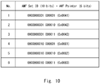
- Figure 10 shows an example of the AMF list managed by the gNB 2.
- the AMF list of Figure 10 shows six AMFs, and these six AMFs are assigned sequence numbers. Accordingly, by using the AMF list of Figure 10 , the six AMFs connected to the gNB 2 can be distinguished by the 3-bit words representing their sequence numbers.
- the example of Figure 10 is merely an example. If the bit length of the AMF sequence number (or identifier) after replacement is smaller than the total size (i.e., 16 bits) of the AMF set ID and the AMF pointer, the data reduction effect can be obtained.
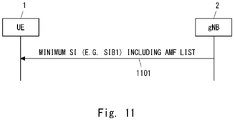
- the gNB 2 periodically broadcasts an AMF list (e.g., Figure 10 ) via minimum SI (e.g., SIB1) or via another SIB (step 1101).
- the UE 1 receives the SIB carrying the AMF list.
- the UE 1 may shorten the AMF set ID and AMF pointer of the 5G-S-TMSI included in an RRC message (e.g., steps 202 and 503) carrying a NAS security parameter.
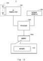
- FIG. 12 is a block diagram showing a configuration example of the UE 1.
- a Radio Frequency (RF) transceiver 1201 performs analog RF signal processing to communicate with NG-RAN nodes.
- the RF transceiver 1201 may include a plurality of transceivers.
- the analog RF signal processing performed by the RF transceiver 1201 includes frequency up-conversion, frequency down-conversion, and amplification.
- the RF transceiver 1201 is coupled to an antenna array 1202 and a baseband processor 1203.
- the RF transceiver 1201 receives modulated symbol data (or OFDM symbol data) from the baseband processor 1203, generates a transmission RF signal, and supplies the transmission RF signal to the antenna array 1202. Further, the RF transceiver 1201 generates a baseband reception signal based on a reception RF signal received by the antenna array 1202 and supplies the baseband reception signal to the baseband processor 1203.
- the RF transceiver 1201 may include an analog beamformer circuit for beam forming.
- the analog beamformer circuit includes, for example, a plurality of phase shifters and a plurality of power amplifiers.
- the baseband processor 1203 performs digital baseband signal processing (i.e., data-plane processing) and control-plane processing for radio communication.
- the digital baseband signal processing includes (a) data compression/decompression, (b) data segmentation/concatenation, (c) composition/decomposition of a transmission format (i.e., transmission frame), (d) channel coding/decoding, (e) modulation (i.e., symbol mapping)/demodulation, and (f) generation of OFDM symbol data (i.e., baseband OFDM signal) by Inverse Fast Fourier Transform (IFFT).
- IFFT Inverse Fast Fourier Transform
- control-plane processing includes communication management of layer 1 (e.g., transmission power control), layer 2 (e.g., radio resource management and hybrid automatic repeat request (HARQ) processing), and layer 3 (e.g., signaling regarding attach, mobility, and call management).
- layer 1 e.g., transmission power control
- layer 2 e.g., radio resource management and hybrid automatic repeat request (HARQ) processing
- layer 3 e.g., signaling regarding attach, mobility, and call management.
- the digital baseband signal processing by the baseband processor 1203 may include, for example, signal processing of a Service Data Adaptation Protocol (SDAP) layer, a Packet Data Convergence Protocol (PDCP) layer, a Radio Link Control (RLC) layer, a Medium Access Control (MAC) layer, and a Physical (PHY) layer. Further, the control-plane processing performed by the baseband processor 1203 may include processing of Non-Access Stratum (NAS) protocols, RRC protocols, and MAC CEs.
- SDAP Service Data Adaptation Protocol
- PDCP Packet Data Convergence Protocol
- RLC Radio Link Control
- MAC Medium Access Control
- PHY Physical
- the baseband processor 1203 may perform Multiple Input Multiple Output (MIMO) encoding and pre-coding for beam forming.
- MIMO Multiple Input Multiple Output
- the baseband processor 1203 may include a modem processor (e.g., Digital Signal Processor (DSP)) that performs the digital baseband signal processing and a protocol stack processor (e.g., a Central Processing Unit (CPU) or a Micro Processing Unit (MPU)) that performs the control-plane processing.
- DSP Digital Signal Processor
- protocol stack processor e.g., a Central Processing Unit (CPU) or a Micro Processing Unit (MPU)
- the protocol stack processor which performs the control-plane processing, may be integrated with an application processor 1204 described in the following.
- the application processor 1204 is also referred to as a CPU, an MPU, a microprocessor, or a processor core.
- the application processor 1204 may include a plurality of processors (or processor cores).
- the application processor 1204 loads a system software program (Operating System (OS)) and various application programs (e.g., a call application, a WEB browser, a mailer, a camera operation application, and a music player application) from a memory 1206 or from another memory (not shown) and executes these programs, thereby providing various functions of the UE 1.
- OS Operating System
- various application programs e.g., a call application, a WEB browser, a mailer, a camera operation application, and a music player application
- the baseband processor 1203 and the application processor 1204 may be integrated on a single chip.
- the baseband processor 1203 and the application processor 1204 may be implemented in a single System on Chip (SoC) device 1205.
- SoC System on Chip
- An SoC device may be referred to as a Large-Scale Integration (LSI) or a chipset.
- the memory 1206 is a volatile memory, a non-volatile memory, or a combination thereof.
- the memory 1206 may include a plurality of memory devices that are physically independent from each other.
- the volatile memory is, for example, a Static Random Access Memory (SRAM), a Dynamic RAM (DRAM), or a combination thereof.
- the non-volatile memory is, for example, a Mask Read Only Memory (MROM), an Electrically Erasable Programmable ROM (EEPROM), a flash memory, a hard disc drive, or any combination thereof.
- the memory 1206 may include, for example, an external memory device that can be accessed from the baseband processor 1203, the application processor 1204, and the SoC 1205.
- the memory 1206 may include an internal memory device that is integrated in the baseband processor 1203, the application processor 1204, or the SoC 1205. Further, the memory 1206 may include a memory in a Universal Integrated Circuit Card (UICC).
- UICC Universal Integrated Circuit Card
- the memory 1206 may store one or more software modules (computer programs) 1207 including instructions and data to perform the processing by the UE 1 described in the above embodiments.
- the baseband processor 1203 or the application processor 1204 may load these software modules 1207 from the memory 1206 and execute the loaded software modules, thereby performing the processing of the UE 1 described in the above embodiments with reference to the drawings.
- control-plane processing and operations performed by the UE 1 described in the above embodiments can be achieved by elements other than the RF transceiver 1201 and the antenna array 1202, i.e., achieved by the memory 1206, which stores the software modules 1207, and one or both of the baseband processor 1203 and the application processor 1204.
- FIG 13 is a block diagram showing a configuration example of the gNB 2 according to the above-described embodiments.
- the gNB 2 includes a Radio Frequency transceiver 1301, a network interface 1303, a processor 1304, and a memory 1305.
- the RF transceiver 1301 performs analog RF signal processing to communicate with UEs including the UE 1.
- the RF transceiver 1301 may include a plurality of transceivers.
- the RF transceiver 1301 is coupled to an antenna array 1302 and the processor 1304.
- the RF transceiver 1301 receives modulated symbol data from the processor 1304, generates a transmission RF signal, and supplies the transmission RF signal to the antenna array 1302.
- the RF transceiver 1301 generates a baseband reception signal based on a reception RF signal received by the antenna array 1302 and supplies the baseband reception signal to the processor 1304.
- the RF transceiver 1301 may include an analog beamformer circuit for beam forming.
- the analog beamformer circuit includes, for example, a plurality of phase shifters and a plurality of power amplifiers.
- the network interface 1303 is used to communicate with network nodes (e.g., the AMF 3 and a Session Management Function (SMF)).
- the network interface 1303 may include, for example, a network interface card (NIC) conforming to the IEEE 802.3 series.
- the processor 1304 performs digital baseband signal processing (i.e., data-plane processing) and control-plane processing for radio communication.
- the processor 1304 may include a plurality of processors.
- the processor 1304 may include, for example, a modem processor (e.g., a Digital Signal Processor (DSP)) that performs digital baseband signal processing and a protocol stack processor (e.g., a Central Processing Unit (CPU) or a Micro Processing Unit (MPU)) that performs the control-plane processing.
- DSP Digital Signal Processor
- a protocol stack processor e.g., a Central Processing Unit (CPU) or a Micro Processing Unit (MPU)
- the digital baseband signal processing by the baseband processor 1304 may include, for example, signal processing of a Service Data Adaptation Protocol (SDAP) layer, a Packet Data Convergence Protocol (PDCP) layer, a Radio Link Control (RLC) layer, a MAC layer, and a PHY layer.
- SDAP Service Data Adaptation Protocol
- PDCP Packet Data Convergence Protocol
- RLC Radio Link Control
- MAC Medium Access Management Entity
- PHY Packet Data Convergence Protocol
- the control-plane processing performed by the baseband processor 1304 may include processing of Non-Access Stratum (NAS) messages, RRC messages, MAC CEs, and DCIs.
- NAS Non-Access Stratum
- the processor 1304 may include a digital beamformer module for beam forming.
- the digital beamformer module may include a Multiple Input Multiple Output (MIMO) encoder and a pre-coder.
- MIMO Multiple Input Multiple Output
- the memory 1305 is composed of a combination of a volatile memory and a non-volatile memory.
- the volatile memory is, for example, a Static Random Access Memory (SRAM), a Dynamic RAM (DRAM), or a combination thereof.
- the non-volatile memory is, for example, a Mask Read Only Memory (MROM), an Electrically Erasable Programmable ROM (EEPROM), a flash memory, a hard disc drive, or any combination thereof.
- the memory 1305 may include a storage located apart from the processor 1304. In this case, the processor 1304 may access the memory 1305 via the network interface 1303 or an I/O interface (not shown).
- the memory 1305 may store one or more software modules (computer programs) 1306 including instructions and data to perform processing by the gNB 2 described in the above embodiments.
- the processor 1304 may be configured to load the software modules 1306 from the memory 1305 and execute the loaded software modules, thereby performing processing of the gNB 2 described in the above embodiments.
- the gNB 2 When the gNB 2 is a gNB-CU, the gNB 2 does not need to include the RF transceiver 1301 (and the antenna array 1302).
- FIG 14 is a block diagram showing a configuration example of the AMF 3.
- the AMF 3 includes a network interface 1401, a processor 1402, and a memory 1403.
- the network interface 1401 is used to communicate, for example, with RAN nodes and with other network functions (NFs) or nodes in the 5GC.
- the other NFs or nodes in the 5GC include, for example, another AMF, a Unified Data Management (UDM), an Authentication Server Function (AUSF), a Session Management Function (SMF), and Policy Control Function (PCF).
- the network interface 1401 may include, for example, a network interface card (NIC) conforming to the IEEE 802.3 series.
- NIC network interface card
- the processor 1402 may be, for example, a microprocessor, a Micro Processing Unit (MPU), or a Central Processing Unit (CPU).
- the processor 1402 may include a plurality of processors.
- the memory 1403 is composed of a volatile memory and a nonvolatile memory.
- the volatile memory is, for example, a Static Random Access Memory (SRAM), a Dynamic RAM (DRAM), or a combination thereof.
- the non-volatile memory is, for example, a Mask Read Only Memory (MROM), an Electrically Erasable Programmable ROM (EEPROM), a flash memory, a hard disc drive, or any combination thereof.
- the memory 1403 may include a storage located apart from the processor 1402. In this case, the processor 1402 may access the memory 1403 via the network interface 1401 or an I/O interface (not illustrated).
- the memory 1403 may store one or more software modules (computer programs) 1404 including instructions and data to perform the processing of the AMF 3 described in the above embodiments.
- the processor 1402 may be configured to load the one or more software modules 1404 from the memory 1403 and execute the loaded software modules, thereby performing the processing of the AMF 3 described in the above embodiments.
- each of the processors that the UE 1, the gNB 2, and the AMF 3 according to the above embodiments include executes one or more programs including instructions for causing a computer to execute an algorithm described with reference to the drawings. These programs can be stored and provided to a computer using any type of non-transitory computer readable media. Non-transitory computer readable media include any type of tangible storage media.
- non-transitory computer readable media examples include magnetic storage media (such as flexible disks, magnetic tapes, hard disk drives, etc.), optical magnetic storage media (e.g., magneto-optical disks), Compact Disc Read Only Memory (CD-ROM), CD-R, CD-R/W, and semiconductor memories (such as mask ROM, Programmable ROM (PROM), Erasable PROM (EPROM), flash ROM, Random Access Memory (RAM), etc.).
- These programs may be provided to a computer using any type of transitory computer readable media. Examples of transitory computer readable media include electric signals, optical signals, and electromagnetic waves. Transitory computer readable media can provide the programs to a computer via a wired communication line (e.g., electric wires, and optical fibers) or a wireless communication line.
- a radio terminal comprising:
- the radio terminal according to Supplementary Note 1, wherein the on-demand system information is broadcast by the RAN node in response to successful authentication that is performed by a core network based on the NAS security parameter.
- NAS security parameter includes one or more bit of a Message Authentication Code for NAS for Integrity (NAS-MAC) calculated by the radio terminal.
- NAS-MAC Message Authentication Code for NAS for Integrity
- the NAS security parameter further includes one or more bits of a NAS COUNT used to calculate the NAS-MAC.
- the at least one processor is configured to receive system information, which is broadcast by the RAN node and includes a list indicating association between the second set of bits and the third set of bits.
- the at least one processor is configured to, after transmitting the message, receive an acknowledgement message from the RAN node, wherein the acknowledgement message indicates a waiting time until broadcast of the on-demand system information is started.
- the radio terminal according to any one of Supplementary Notes 1 to 8, wherein the procedure is a random access procedure to request the system information.
- a Radio Access Network (RAN) node comprising:
- NAS security parameter includes one or more bits of a Message Authentication Code for NAS for Integrity (NAS-MAC) calculated by the radio terminal.
- NAS-MAC Message Authentication Code for NAS for Integrity
- NAS security parameter further includes one or more bits of a NAS COUNT used to calculate the NAS-MAC.
- the RAN node according to any one of Supplementary Notes 10 to 12, wherein the message received from the radio terminal further includes:
- the RAN node according to Supplementary Note 13, wherein the at least one processor is configured to estimate the temporary identifier from the first set of bits and the third set of bits received form the radio terminal and include the temporary identifier in the authentication request message.
- the RAN node according to Supplementary Note 13 or 14, wherein the at least one processor is configured to periodically broadcast system information including a list indicating association between the second set of bits and the third set of bits.
- the RAN node according to any one of Supplementary Notes 10 to 16, wherein the at least one processor is configured to include, in the authentication request message, a plurality of NAS security parameters each received from a respective one of a plurality of radio terminals that have requested broadcast of the system information.
- the RAN node according to Supplementary Note 17, wherein the authentication response message is sent by the core network node in response to successful authentication of at least one of the plurality of radio terminals.
- the RAN node according to any one of Supplementary Notes 10 to 18, wherein the at least one processor is configured to, after receiving the message from the radio terminal, transmit an acknowledgement message to the radio terminal, wherein the acknowledgement message indicates a waiting time until broadcast of the on-demand system information is started.
- the RAN node according to any one of Supplementary Notes 10 to 19, wherein the procedure is a random access procedure to request the system information.
- a core network node comprising:
- the core network node according to Supplementary Note 21, wherein the authentication response message is used by the RAN node to determine whether to broadcast the on-demand system information.
- the core network node according to Supplementary Note 21 or 22, wherein if the authentication response message indicates successful authentication, the authentication response message triggers the RAN node to broadcast the on-demand system information.
- NAS security parameter includes one or more bits of a Message Authentication Code for NAS for Integrity (NAS-MAC) calculated by the radio terminal.
- NAS-MAC Message Authentication Code for NAS for Integrity
- NAS security parameter further includes one or more bits of a NAS COUNT used to calculate the NAS-MAC.
- the core network node according to any one of Supplementary Notes 21 to 25, wherein the authentication request message includes a plurality of NAS security parameters each received by the RAN node from a respective one of a plurality of radio terminals that have requested broadcast of the system information.
- the core network node according to Supplementary Note 26, wherein the at least one processor is configured to send the authentication response message in response to successful authentication of at least one of the plurality of radio terminals.
- a method performed by a radio terminal comprising transmitting a message containing a Non-Access Stratum (NAS) security parameter to a Radio Access Network (RAN) node, during a procedure for requesting the RAN node to broadcast on-demand system information.
- NAS Non-Access Stratum
- RAN Radio Access Network
- a method performed by a Radio Access Network (RAN) node comprising:
- a method performed by a core network node comprising:
- a program for causing a computer to perform a method for a radio terminal comprising transmitting a message containing a Non-Access Stratum (NAS) security parameter to a Radio Access Network (RAN) node, during a procedure for requesting the RAN node to broadcast on-demand system information.
- NAS Non-Access Stratum
- RAN Radio Access Network
Landscapes
- Engineering & Computer Science (AREA)
- Computer Security & Cryptography (AREA)
- Computer Networks & Wireless Communication (AREA)
- Signal Processing (AREA)
- Mobile Radio Communication Systems (AREA)
Abstract
Description
- The present disclosure relates to a radio communication network and, in particular, to broadcasting of on-demand system information.
- In the 5G system (5GS), System Information (SI) includes a Master Information Block and a number of System Information Blocks (SIBs), which are divided into Minimum SI and Other SI. The Minimum SI is always being broadcast periodically and contains basic information required for initial access and information for acquiring any other SI. Specifically, the Minimum SI contains MIB and SIB type 1 (SIB1).
- MIB is periodically transmitted on a Broadcast Channel (BCH) and a Physical Broadcast Channel (PBCH). The MIB contains information regarding cell barring and further contains essential physical layer information of the cell required to decode SIB1. More specifically, the MIB indicates a System Frame Number (SFN), a subcarrier spacing (subCarrierSpacingCommon) for SIB1, and a Physical Downlink Control Channel (PDCCH) configuration required to decode SIB1.
- SIB1 is periodically transmitted on a Downlink Shared Channel (DL-SCH) and a Physical Downlink Shared Channel (PDSCH). SIB1 indicates the availability and scheduling (e.g., periodicity and SI-window size) of Other SI (Other SIBs). SIB1 further indicates whether Other SIBs are provided via periodic broadcast or on-demand basis. Furthermore, SIB1 incudes information required for initial access.
- Other SI includes all SIBs that are not broadcast within Minimum SI. These SIBs can be periodically broadcast on a DL-SCH, broadcast on-demand on a DL-SCH (i.e., upon request from User Equipments (UEs) in Resource Control (RRC)_IDLE or RRC_INACTIVE), or sent in a dedicated manner on a DL-SCH to UEs in RRC_CONNECTED. Other SI includes SIB2 to SIB9.
- As mentioned above, in the 5GS, Other SI can be broadcast on-demand. Specifically, if required system information is not being broadcast, a UE in RRC_IDLE or RRC_INACTIVE send a request for specific system information to a Radio Access Network (RAN) node (e.g., base station, gNB). The request is sent during a contention-based random access procedure. Upon receiving the request from the UE, the RAN node broadcasts the requested system information.
- More specifically, if a subset of random access resources (i.e., Physical Random Access Channel (PRACH) resources) for requesting the required system information is provided by SIB1, the UE selects a random access preamble from the subset and transmits the selected preamble. That is, in this case, the SI request is transmitted via a random access preamble, i.e., the first message (Msg1) of a (4-step) random access procedure. Otherwise, the UE transmits an SI request message (i.e., RRCSystemInfoRequest message) via initial RRC message transmission (i.e., the third message (Msg3) of the (4-step) random access procedure). The UE includes in the RRCSystemInfoRequest message a list (i.e., requested-SI-List) indicating required system information messages.
- The system information of the 5GS and acquisition thereof are described, for example, in Section 7.3 of
Non-Patent Literature 1 and Section 5.2.2.3 ofNon-Patent Literature 2. - In this specification, the term "on-demand system information (SI)" is used. The on-demand SI means system information that is broadcast on-demand in response to a request from a radio terminal (e.g., UE), such as Other SI of the 5GS. In other words, the on-demand SI is system information that is not always periodically broadcast but is broadcast on-demand in response to a request from a radio terminal (e.g., UE).
- [Non-Patent Literature 1] 3GPP TS 38.300 V15.8.0 (2019-12) "3rd Generation Partnership Project; Technical Specification Group Radio Access Network; NR; NR and NG-RAN Overall Description; Stage 2 (Release 15)", December 2019 [Non-Patent Literature 2] 3GPP TS 38.331 V15.8.0 (2019-12) "3rd Generation Partnership Project; Technical Specification Group Radio Access Network; NR; Radio Resource Control (RRC) protocol specification (Release 15)", December 2019
- The inventor has studied a procedure for requesting on-demand SI and found various problems. Specifically, for example, a RAN node (e.g., gNB) cannot identify or authenticate a radio terminal (e.g., UE) in a random access procedure for on-demand SI request. Accordingly, even if a malicious radio terminal requests the transmission of on-demand SI, the RAN node broadcasts the on-demand SI in response to the request. This may waste RAN node resources and radio resources.
- One of the objects to be attained by embodiments disclosed herein is to provide apparatuses, methods, and programs that contribute to preventing on-demand SI from being broadcast in response to a request from a malicious radio terminal. It should be noted that this object is merely one of the objects to be attained by the embodiments disclosed herein. Other objects or problems and novel features will be made apparent from the following description and the accompanying drawings.
- In a first aspect, a radio terminal includes at least one memory and at least one processor coupled to the at least one memory. The at least one processor is configured to transmit a message containing a Non-Access Stratum (NAS) security parameter to a RAN node, during a procedure for requesting the RAN node to broadcast on-demand SI.
- In a second aspect, a RAN node includes at least one memory and at least one processor coupled to the at least one memory. The at least one processor is configured to receive a message containing a Non-Access Stratum (NAS) security parameter from a radio terminal, during a procedure in which the radio terminal requests the RAN node to broadcast on-demand SI. The at least one processor is further configured to send an authentication request message containing the NAS security parameter to a core network node, in order to request authentication of the radio terminal. Furthermore, the at least one processor is configured to broadcast the on-demand SI in response to receiving from the core network node an authentication response message indicating successful authentication of the radio terminal.
- In a third aspect, a core network node includes at least one memory and at least one processor coupled to the at least one memory. The at least one processor is configured to receive an authentication request message from a Radio Access Network (RAN) node. The authentication request message contains a NAS security parameter being transmitted from a radio terminal during a procedure in which the radio terminal requests the RAN node to broadcast on-demand SI. The at least one processor is further configured to send to the RAN node an authentication response message indicating whether authentication based on the NAS security parameter is successful or not.
- In a fourth aspect, a method performed by a radio terminal includes transmitting a message containing a Non-Access Stratum (NAS) security parameter to a Radio Access Network (RAN) node, during a procedure for requesting the RAN node to broadcast on-demand SI.
- In a fifth aspect, a method performed by a RAN node includes the following steps:
- (a) receiving a message containing a Non-Access Stratum (NAS) security parameter from a radio terminal, during a procedure in which the radio terminal requests the RAN node to broadcast on-demand SI;
- (b) sending an authentication request message containing the NAS security parameter to a core network node, in order to request authentication of the radio terminal; and
- (c) broadcasting the on-demand SI in response to receiving from the core network node an authentication response message indicating successful authentication of the radio terminal.
- In a sixth aspect, a method performed by a core network node includes the following steps:
- (a) receiving an authentication request message from a Radio Access Network (RAN) node, the authentication request message containing a NAS security parameter being transmitted from a radio terminal during a procedure in which the radio terminal requests the RAN node to broadcast on-demand SI; and
- (b) sending to the RAN node an authentication response message indicating whether authentication based on the NAS security parameter is successful or not.
- In a seventh aspect, a program includes instructions (software codes) that, when loaded into a computer, cause the computer to perform the method according to the above-described fourth, fifth, or sixth aspect.
- According to the above-described aspects, it is possible to provide apparatuses, methods, and programs that contribute to preventing on-demand SI from being broadcast in response to a request from malicious a radio terminal.
-
-
Figure 1 is a diagram showing a configuration example of a radio communication network according to embodiments; -
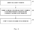
Figure 2 is a flowchart showing an example of operation of a radio terminal (e.g., UE) according to an embodiment; -
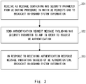
Figure 3 is a flowchart showing an example of operation of a RAN node (e.g., gNB) according to an embodiment; -
Figure 4 is a flowchart showing an example of operation of a core network node (e.g., AMF) according to an embodiment; -
Figure 5 is a sequence diagram showing a procedure for requesting on-demand SI; -
Figure 6 is a flowchart showing an example of operation of a RAN node (e.g., gNB) according to an embodiment; -
Figure 7 is a flowchart showing an example of operation of a core network node (e.g., AMF) according to an embodiment; -
Figure 8 is a flowchart showing an example of operation of a RAN node (e.g., gNB) according to an embodiment; -
Figure 9 is a flowchart showing an example of operation of a core network node (e.g., AMF) according to an embodiment; -
Figure 10 is a diagram showing an example of an AMF list according to an embodiment; -
Figure 11 is a diagram showing an example of AMF list transmission according to an embodiment; -
Figure 12 is a block diagram showing a configuration example of a radio terminal (e.g., UE) according to embodiments; -
Figure 13 is a block diagram showing a configuration example of a RAN node (e.g., gNB) according to embodiments; and -
Figure 14 is a block diagram showing a configuration example of a core network node (e.g., AMF) according to embodiments. - Specific embodiments will be described hereinafter in detail with reference to the drawings. The same or corresponding elements are denoted by the same symbols throughout the drawings, and duplicated explanations are omitted as necessary for the sake of clarity.
- Each of the embodiments described below may be used individually, or two or more of the embodiments may be appropriately combined with one another. These embodiments include novel features different from each other. Accordingly, these embodiments contribute to attaining objects or solving problems different from one another and contribute to obtaining advantages different from one another.
- The following descriptions on the embodiments mainly focus on the 3rd Generation Partnership Project (3GPP) fifth generation mobile communication system (5G system (5GS)). However, these embodiments may be applied to other cellular communication systems that support on-demand SI transmission similar to that of the 5GS.
-
Figure 1 shows a configuration example of a radio communication network (i.e., 5GS) according to the present embodiment. Each of the elements shown inFigure 1 is a network function and provides an interface(s) defined by the 3GPP. Each element (or network function) shown inFigure 1 can be implemented, for example, as a network element on dedicated hardware, as a software instance running on dedicated hardware, or as on a virtualized function instantiated on an application platform. - The radio communication network shown in
Figure 1 may be provided by a Mobile Network Operator (MNO) or may be a Non-Public Network (NPN) provided by a non-MNO. When the cellular network shown inFigure 1 is an NPN, it may be an independent network called a Stand-alone Non-Public Network (SNPN) or an NPN linked with an MNO network called a public network integrated NPN. - In the example of
Figure 1 , the radio communication network includes a radio terminal (i.e., UE) 1, a RAN node (i.e., gNB) 2, and a core network node (i.e., Access and Mobility Management Function (AMF)) 3. ThegNB 2 is arranged in a RAN (i.e., Next Generation Radio Access Network (NG-RAN)). ThegNB 2 may include a gNB Central Unit (gNB-CU) and one or more gNB Distributed Units (gNB-DU) in a cloud RAN (C-RAN) deployment. - The
AMF 3 is one of the network functions in the 5G Core Network (5GC) Control Plane. TheAMF 3 provides the termination of a RAN Control Plane (CP) interface (i.e., N2 interface). TheAMF 3 terminates a single signaling connection (i.e., N1 NAS signaling connection) with theUE 1 and provides registration management, connection management, and mobility management. The AMF3 provides NF services (services) to NF service consumers (e.g., other AMF, Session Management Function (SMF), and Authentication Server Function (AUSF)) on a service-based interface (i.e., Namf interface). - The following provides a description on a procedure for requesting on-demand SI according to the embodiment. In the present embodiment, Non-Access Stratum (NAS) security set up between the
UE 1 and the 5GC (AMF 3) is used to determine whether an on-demand SI request (orUE 1 that transmitted it) is reliable or not. - More specifically, the
UE 1 transmits a message containing a NAS security parameter to thegNB 2 during a procedure (i.e., random access procedure) for requesting thegNB 2 to transmit (or broadcast) on-demand SI. TheUE 1 may transmit an Access Stratum (AS) message (e.g., Radio Resource Control (RRC) message) containing the NAS security parameter. - The
gNB 2 retrieves the NAS security parameter from the message (e.g., RRC message) received from theUE 1. Then, in order to request authentication of theUE 1, thegNB 2 sends to theAMF 3 an authentication request message including the NAS security parameter received from theUE 1. The authentication request message may be a newly defined N2 message (e.g., Authentication Required message). The authentication request message may include a cause IE indicating UE authentication for sending on-demand SI. - In response to receiving the authentication request message from the
gNB 2, theAMF 3 performs verification using the received NAS security parameter. This causes theAMF 3 to determine whether the genuine UE has transmitted the NAS security parameter (or on-demand SI request). TheAMF 3 then sends an authentication response message to thegNB 2. The authentication response message indicates the result (i.e., success or failure) of the UE authentication based on the NAS security parameter. - The authentication response message is used by the
gNB 2 to determine whether to broadcast the requested on-demand SI. Specifically, thegNB 2 broadcasts the requested on-demand SI in response to receiving from theAMF 3 the authentication response message indicating that the authentication of theUE 1 is successful. In other words, if the authentication response message indicates the success of the UE authentication, the authentication response message triggers thegNB 2 to broadcast the on-demand SI. On the other hand, if the authentication response message indicates the failure of the UE authentication, thegNB 2 does not need to broadcast the requested on-demand SI. - According to the above-described operation, the
gNB 2 uses the NAS security set up between theUE 1 and the 5GC (AMF 3) to determine whether the on-demand SI request (or theUE 1 that transmitted it) is reliable. This behavior therefore can prevent the on-demand SI from being broadcast in response to a request from a malicious UE. -
Figure 2 shows an example of the operation of theUE 1. Instep 201, theUE 1 generates a NAS security parameter. More specifically, the AS part (e.g., Radio Resource Control (RRC) layer) of theUE 1 triggers the NAS part of theUE 1 to provide the NAS security parameter. - In some implementations, the NAS security parameter includes a part of the bits of the Message Authentication Code for NAS for Integrity (NAS-MAC) calculated by the
UE 1. The NAS security parameter may include the UL_NAS_MAC formed by a part of the 32 bits NAS-MAC (e.g., the first 16 bits). The NAS security parameter may further include a part (e.g., the lowest 5 bits (5 least significant bits (LSB)) of the bits of the NAS COUNT used to calculate the NAS-MAC. - In
step 202, theUE 1 transmits an AS message (e.g., RRC message) containing the NAS security parameter to thegNB 2 during a procedure of requesting thegNB 2 to broadcast required on-demand SI. As described above, the procedure may be a random access procedure. In this case, theUE 1 may send the NAS security parameter via a third message (Msg3) of a 4-step random access procedure, i.e., via an initial RRC message. - The AS message (e.g., RRC message) in
step 202 may include at least a part of a UE temporary identifier assigned to theUE 1 by the 5GC (e.g., AMF 3). The UE temporary identifier is used, for example, for contention resolution by thegNB 2, for routing (or AMF selection) by thegNB 2, and for UE identification by theAMF 3. The temporary identifier may be a 5G-S-Temporary Mobile Subscription Identifier (5G-S-TMSI). The 5G-S-TMSI has a 48-bit length. The 5G-S-TMSI consists of an AMF set ID (10 bits), an AMF pointer (6 bits), and a 5G TMSI (32 bits). - In the current 3GPP specifications, the bit length of the RRC message is 48 bits or 64 bits. Accordingly, if needed, the size (bit length) of the one or more information elements (i.e., the NAS security parameter, or the part of the UE temporary identifier, or both) carried by the 48-bit or 64-bit RRC message (step 202) may be adjusted. Details of this will be described in another embodiment described below.
- In
step 203, theUE 1 attempts to receive the on-demand SI. Specifically, when theUE 1 receives an acknowledgment for the SI request from thegNB 2, theUE 1 attempts (or starts) the reception of the on-demand SI. The acknowledgment for the SI request may be a fourth message (Msg4) of the random access procedure. The Msg4 contains a MAC Protocol Data Unit (PDU) that carries a UE Contention Resolution Identity Medium Access Control (MAC) Control Element (CE). -
Figure 3 shows an example of the operation of thegNB 2. Instep 301, thegNB 2 receives an AS message (e.g., RRC message) containing a NAS security parameter from theUE 1 during a procedure in which theUE 1 requests thegNB 2 to broadcast on-demand SI. As described above, the procedure may be a random access procedure. In this case, thegNB 2 may receive the NAS security parameter via a third message (Msg3) of a 4-step random access procedure, i.e., via an initial RRC message. Specific examples of the NAS security parameter are similar to those described with respect toFigure 2 . In addition, as described with respect toFigure 2 , the AS message instep 301 may include at least a portion of a UE temporary identifier (e.g., 5G-S-TMSI). - In
step 302, thegNB 2 sends an authentication request message including the NAS security parameter to theAMF 3 in order to request UE authentication. ThegNB 2 may select theAMF 3 based on the UE temporary identifier (e.g., 5G-S-TMSI) included in the AS message instep 301. The authentication request message may be a newly defined N2 message (e.g., Authentication Required message). The authentication request message may include a cause IE indicating UE authentication for sending on-demand SI. - In
step 303, thegNB 2 receives an authentication response message indicating the result (i.e., success or failure) of the UE authentication from theAMF 3. If the authentication response message indicates the success of the UE authentication, then thegNB 2 broadcasts the requested on-demand SI. -
Figure 4 shows an example of the operation of theAMF 3. Instep 401, theAMF 3 receives an authentication request message from thegNB 2. The authentication request message includes a NAS security parameter transmitted by theUE 1 during a procedure in which theUE 1 requests thegNB 2 to broadcast on-demand SI. Specific examples of the NAS security parameter are similar to those described with respect toFigure 2 . The authentication request message may be a newly defined N2 message (e.g., Authentication Required message). The authentication request message may include a cause IE indicating UE authentication for sending on-demand SI. - In
step 402, theAMF 3 performs verification using the received NAS security parameter. TheAMF 3 then sends an authentication response message to thegNB 2. The authentication response message indicates the result (i.e., success or failure) of the UE authentication based on the NAS security parameter. -
Figure 5 shows an example of an on-demand SI request procedure according to the present embodiment.Steps 501 to 504 correspond to the first to fourth steps of the 4-step contention-based random access procedure. Instep 501, theUE 1 transmits a random access preamble for an on-demand SI request. More specifically, if SIB1 provides a subset of random access resources (i.e., PRACH resources) for required on-demand SI, the UE selects a random access preamble from this subset and transits the selected preamble. Otherwise, theUE 1 selects a random access preamble from the normal random access resources and sends the selected preamble. - In
step 502, thegNB 2 transmits a random access response (Random Access Response (RAR)). The RAR indicates a detected preamble identifier, timing alignment information, an initial uplink resource grant for sending the third message, and an assignment of a temporary Cell Radio Network Temporary Identifier (C-RNTI). - In
step 503, in response to receiving the RAR, theUE 1 transmits an RRC message regarding the on-demand SI request. The RRC message includes a NAS security parameter. Specifically, the RRC message contains an UL_NAS_MAC consisting of a part (e.g., the first 16 bits) of the bits of a NAS-MAC calculated by theUE 1, and also contains a part (e.g., the lowest 5 bits) of the bits of a NAS COUNT which was used to calculate the NAS-MAC. The RRC message further includes at least a portion of a 5G-S-TMSI assigned to theUE 1 by the 5GC (i.e., AMF3). - The RRC message in
step 503 may or may not include a list (i.e., requested-SI-List) indicating required system information messages. Specifically, if SIB1 provides a subset of random access resources (i.e., PRACH resources) for required on-demand SI, then the RRC message does not need to include a requested-SI-List. - The RRC message in
step 503 may be a modification (e.g., RRCSystemInfoRequest1 message) of the existing RRCSystemInfoRequest message. Specifically, the existing RRCSystemInfoRequest message is 48 bits long, whereas the RRC message instep 503 may be 64 bits long. - In
step 504, thegNB 2 transmits a fourth message (Msg4) for contention resolution. The Msg4 includes a MAC PDU that carries a UE Contention Resolution Identity MAC CE. - In
step 505, thegNB 2 sends an authentication request message (e.g., N2: Authentication Required message) to theAMF 3. The authentication request message includes the NAS security parameter (i.e., UL_NAS_MAC and a part of NAS COUNT), which has been received from the UE instep 503. - The authentication request message further includes a 5G-S-TMSI of the
UE 1. If the RRC message instep 503 contains only part of the 5G-S-TMSI, thegNB 2 may estimate the entire 5G-S-TMSI. - The authentication request message may include other parameters related to the NAS security. For example, the authentication request message may include other parameters necessary for calculating NAS-MAC/XNAS-MAC in the Integrity Algorithm used for the NAS security. In one example, a Cell-ID may be used as the message to be protected in the calculation of the NAS-MAC by the
UE 1. In this case, thegNB 2 may include the Cell-ID in the authentication request message. - The authentication request message may include a cause IE indicating UE authentication for sending on-demand SI.
- In
step 506, theAMF 3 performs UE authentication based on the received NAS security parameter (i.e., UL_NAS_MAC and a part of NAS COUNT). Specifically, theAMF 3 calculates the XNAS-MAC using the same inputs that theUE 1 used to calculate the NAS-MAC. Then, theAMF 3 compares the received UL_NAS_MAC with the corresponding bits (e.g., the first 16 bits) of the XNAS-MAC. If they are the same, theAMF 3 determines that the UE authentication is successful. In other words, theAMF 3 determines that the genuine UE has transmitted the NAS security parameter (or on-demand SI request). - For example, in the NAS-MAC/XNAS-MAC calculation, the 32-bit NAS COUNT, the 5-bit bearer identity (i.e., BEARER), the 1-bit direction of transmission (i.e., DIRECTION), and the message to be protected (i.e., MESSAGE) is used. The
AMF 3 estimates the entire uplink NAS COUNT from the part (e.g., 5 LSB) of the received NAS COUNT. Specifically, theAMF 3 may replace the corresponding bits of the 32-bit uplink NAS COUNT managed by theAMF 3 itself with the part (e.g., 5 LSB) of the NAS COUNT received from theUE 1 via thegNB 2. The BEARER bits are a predetermined fixed value (e.g., zero). The DIRECTION bit is zero for the uplink. The MESSAGE bits may be a predetermined fixed value or may be a Cell-ID as described above. - The
AMF 3 sends an authentication response message indicating the result of the UE authentication to thegNB 2. The AMF3 may send an authentication success message (e.g., N2: Authentication Confirm message) if the UE authentication is successful, and it may send an authentication failure message (e.g., N2: Authentication Failure message) if the UE authentication is unsuccessful. - In
step 507, thegNB 2 broadcasts the requested on-demand SI in response to receiving the authentication response message indicating the success of UE authentication. TheUE 1 attempts to receive the on-demand SI after receiving the acknowledgement message (Msg4) instep 504 and receives the on-demand SI instep 507. - The procedure shown in
Figure 5 is an example and can be appropriately modified. For example, the 4-step random access procedure ofFigure 5 may be changed to a 2-step random access procedure. The 2-step random access procedure includes sending a message A from theUE 1 to thegNB 2 and sending a message B from thegNB 2 to theUE 1. The message A may include the same information as the first message (step 501) and the third message (step 503) of the 4-step random access procedure. The message B may include information for contention resolution similar to the fourth message (step 504) of the 4-step random access procedure. - Additionally, or alternatively, in
step 504, thegNB 2 may include in the acknowledgement message (Msg4) an indication indicating a waiting time until broadcast of the on-demand SI is started. The waiting time may be determined based on the time required to complete the UE authentication (steps 505 and 506). The waiting time may be dynamically determined by thegNB 2. TheUE 1 may delay the start of the attempt of on-demand SI reception in consideration of the waiting time of which theUE 1 was notified by gNB2. As a result, theUE 1 does not need to start receiving the on-demand SI immediately after receiving the acknowledgement message (Msg4), and accordingly the power consumption of the UE1 can be suppressed. - Additionally, or alternatively, the transmission (step 504) of the acknowledgement message (Msg4) may be performed after the UE authentication (
steps 505 and 506). - This embodiment provides a modified example of the first embodiment. A configuration example of a radio communication network according to the present embodiment is the same as that shown in
Figure 1 . -
Figure 6 shows an example of the operation of thegNB 2 according to the present embodiment. Instep 601 thegNB 2 generates a single authentication request message containing a plurality of NAS security parameters received from a plurality of theUEs 1. ThegNB 2 may aggregate SI requests from a plurality of UEs received within a predetermined time window. In some implementations, thegNB 2 may generate one authentication request message containing multiple NAS security parameters received frommultiple UEs 1 managed by thesame AMF 3. Alternatively, thegNB 2 may generate one authentication request message containing multiple NAS security parameters received frommultiple UEs 1 managed by thesame AMF 3 and requesting the same on-demand SI message. Instep 602, thegNB 2 sends the generated authentication request message to theAMF 3. -
Figure 7 shows an example of the operation of theAMF 3 according to this embodiment. Instep 701, theAMF 3 receives from the gNB 2 a single authentication request message including a plurality of NAS security parameters sent from a plurality ofUEs 1. Instep 702, theAMF 3 sends a single authentication response message indicating the respective authentication results of the plurality of UEs to thegNB 2. ThegNB 2 broadcasts one or more on-demand SI messages requested by one or more successfully authenticated UEs. - As described above, in the present embodiment, the
gNB 2 sends a single authentication request message including a plurality of NAS security parameters received from a plurality ofUEs 1 to theAMF 3, and theAMF 3 sends to thegNB 2 an authentication response message indicating the authentication result of each of these UEs. This contributes to reducing the number of times the authentication request and authentication response messages are sent and received. - This embodiment provides a modified example of the second embodiment. A configuration example of a radio communication network according to the present embodiment is the same as that shown in
Figure 1 . -
Figure 8 shows an example of the operation of thegNB 2 according to the present embodiment. Instep 801 thegNB 2 generates a single authentication request message containing a plurality of NAS security parameters received from a plurality ofUEs 1 managed by thesame AMF 3 and requesting the same on-demand SI message. ThegNB 2 may aggregate SI requests from a plurality of UEs received within a predetermined time window. Instep 802, thegNB 2 sends the generated authentication request message to theAMF 3. -
Figure 9 shows an example of the operation of theAMF 3 according to this embodiment. Instep 901, theAMF 3 receives an authentication request message from thegNB 2. The authentication request message includes a plurality of NAS security parameters that have been received from a plurality ofUEs 1 requesting the same on-demand SI message. - In
step 902, the AMF3 sends an authentication response message indicating successful authentication, in response to successful authentication of at least one of the plurality of UEs. The authentication response message does not need to show the respective authentication results of the plurality of UEs, and it is sufficient to show the result of one authentication. If theAMF 3 succeeds in authenticating one of the multiple UEs associated with one authentication request message, it may skip (or omit) the authentications of the remaining UEs. If theAMF 3 succeeds in authenticating one of the multiple UEs associated with one authentication request message, it may immediately send an authentication response message indicating successful authentication without waiting for the authentications of the remaining UEs to be completed. ThegNB 2 broadcasts the requested on-demand SI message in response to receiving the authentication response message indicating successful authentication. - As described above, in the present embodiment, the
gNB 2 sends to the AMF 3 a single authentication request message including a plurality of NAS security parameters received from a plurality ofUEs 1 that are managed by thesame AMF 3 and request the same on-demand SI message. Then, theAMF 3 sends an authentication response message indicating successful authentication in response to the success of the authentication of at least one of the plurality of UEs. This makes the UE authentication suitable for on-demand SI transmission purposes. - Specifically, if the
AMF 3 succeeds in authenticating one UE out of multiple UEs associated with one authentication request message, it can skip (or omit) the authentications of the remaining UEs. This allows the load of UE authentications in theAMF 3 to be reduced. In addition, if theAMF 3 succeeds in authenticating one of multiple UEs associated with one authentication request message, it can immediately send an authentication response message indicating successful authentication without waiting for the authentications of the remaining UEs to be completed. This can reduce the delay in starting the on-demand SI broadcast. - This embodiment provides a modified example of the first embodiment. A configuration example of a radio communication network according to the present embodiment is the same as that shown in
Figure 1 . This embodiment is aimed at reducing the size of data to be transmitted by an AS message (e.g., RRC messages) from theUE 1 to thegNB 2 for an on-demand SI request. - As already described, in the current 3GPP specifications, the bit length of the RRC message is 48 bits or 64 bits. This embodiment provides specific examples of adjusting the size (bit length) of one or more information elements (i.e., NAS security parameter, or part of a UE temporary identifier, or both) carried by the 48-bit or 64-bit RRC message (e.g., steps 202 and 503). The specific examples shown below may be used in combination as appropriate.
- In the first example, the size of UL_NAS_MAC included in a NAS security parameter is adjusted. If a 64-bit RRC message contains the NAS security parameter in addition to 5G-S-TMSI (48 bits), the NAS security parameter must be 16 bits or less. This reduces the number of bits in the UL_NAS_MAC. For example, the
UE 1 may use the first 11 bits or less of the calculated NAS_MAC as the UL_NAS_MAC. - In the second example, the size of a part of UL COUNT included in the NAS security parameter is adjusted. For example, the
UE 1 may transmit theLSB 4 bits orLSB 3 bits of the NAS COUNT. - In the third example, 5G-S-TMSI is shortened. The complete 5G-S-TMSI has a 48-bit length and consists of an AMF set ID (10 bits), an AMF pointer (6 bits), and a 5G TMSI (32 bits). Shortening the 5G TMSI is not appropriate as it makes the UE identification by the
AMF 3 difficult. On the other hand, the AMF set ID and AMF pointer may be replaced with a shortened bit sequence as shown below. - The
gNB 2 manages a list of AMFs to which thegNB 2 is connected.Figure 10 shows an example of the AMF list managed by thegNB 2. The AMF list ofFigure 10 shows six AMFs, and these six AMFs are assigned sequence numbers. Accordingly, by using the AMF list ofFigure 10 , the six AMFs connected to thegNB 2 can be distinguished by the 3-bit words representing their sequence numbers. The example ofFigure 10 is merely an example. If the bit length of the AMF sequence number (or identifier) after replacement is smaller than the total size (i.e., 16 bits) of the AMF set ID and the AMF pointer, the data reduction effect can be obtained. - In some implementations, as shown in
Figure 11 , thegNB 2 periodically broadcasts an AMF list (e.g.,Figure 10 ) via minimum SI (e.g., SIB1) or via another SIB (step 1101). TheUE 1 receives the SIB carrying the AMF list. Then, using this list, theUE 1 may shorten the AMF set ID and AMF pointer of the 5G-S-TMSI included in an RRC message (e.g., steps 202 and 503) carrying a NAS security parameter. - The following provides configuration examples of the
UE 1, thegNB 2, and theAMF 3 according to the above-described embodiments.Figure 12 is a block diagram showing a configuration example of theUE 1. A Radio Frequency (RF)transceiver 1201 performs analog RF signal processing to communicate with NG-RAN nodes. TheRF transceiver 1201 may include a plurality of transceivers. The analog RF signal processing performed by theRF transceiver 1201 includes frequency up-conversion, frequency down-conversion, and amplification. TheRF transceiver 1201 is coupled to an antenna array 1202 and abaseband processor 1203. TheRF transceiver 1201 receives modulated symbol data (or OFDM symbol data) from thebaseband processor 1203, generates a transmission RF signal, and supplies the transmission RF signal to the antenna array 1202. Further, theRF transceiver 1201 generates a baseband reception signal based on a reception RF signal received by the antenna array 1202 and supplies the baseband reception signal to thebaseband processor 1203. TheRF transceiver 1201 may include an analog beamformer circuit for beam forming. The analog beamformer circuit includes, for example, a plurality of phase shifters and a plurality of power amplifiers. - The
baseband processor 1203 performs digital baseband signal processing (i.e., data-plane processing) and control-plane processing for radio communication. The digital baseband signal processing includes (a) data compression/decompression, (b) data segmentation/concatenation, (c) composition/decomposition of a transmission format (i.e., transmission frame), (d) channel coding/decoding, (e) modulation (i.e., symbol mapping)/demodulation, and (f) generation of OFDM symbol data (i.e., baseband OFDM signal) by Inverse Fast Fourier Transform (IFFT). Meanwhile, the control-plane processing includes communication management of layer 1 (e.g., transmission power control), layer 2 (e.g., radio resource management and hybrid automatic repeat request (HARQ) processing), and layer 3 (e.g., signaling regarding attach, mobility, and call management). - The digital baseband signal processing by the
baseband processor 1203 may include, for example, signal processing of a Service Data Adaptation Protocol (SDAP) layer, a Packet Data Convergence Protocol (PDCP) layer, a Radio Link Control (RLC) layer, a Medium Access Control (MAC) layer, and a Physical (PHY) layer. Further, the control-plane processing performed by thebaseband processor 1203 may include processing of Non-Access Stratum (NAS) protocols, RRC protocols, and MAC CEs. - The
baseband processor 1203 may perform Multiple Input Multiple Output (MIMO) encoding and pre-coding for beam forming. - The
baseband processor 1203 may include a modem processor (e.g., Digital Signal Processor (DSP)) that performs the digital baseband signal processing and a protocol stack processor (e.g., a Central Processing Unit (CPU) or a Micro Processing Unit (MPU)) that performs the control-plane processing. In this case, the protocol stack processor, which performs the control-plane processing, may be integrated with anapplication processor 1204 described in the following. - The
application processor 1204 is also referred to as a CPU, an MPU, a microprocessor, or a processor core. Theapplication processor 1204 may include a plurality of processors (or processor cores). Theapplication processor 1204 loads a system software program (Operating System (OS)) and various application programs (e.g., a call application, a WEB browser, a mailer, a camera operation application, and a music player application) from amemory 1206 or from another memory (not shown) and executes these programs, thereby providing various functions of theUE 1. - In some implementations, as represented by a dashed line (1205) in
Figure 12 , thebaseband processor 1203 and theapplication processor 1204 may be integrated on a single chip. In other words, thebaseband processor 1203 and theapplication processor 1204 may be implemented in a single System on Chip (SoC)device 1205. An SoC device may be referred to as a Large-Scale Integration (LSI) or a chipset. - The
memory 1206 is a volatile memory, a non-volatile memory, or a combination thereof. Thememory 1206 may include a plurality of memory devices that are physically independent from each other. The volatile memory is, for example, a Static Random Access Memory (SRAM), a Dynamic RAM (DRAM), or a combination thereof. The non-volatile memory is, for example, a Mask Read Only Memory (MROM), an Electrically Erasable Programmable ROM (EEPROM), a flash memory, a hard disc drive, or any combination thereof. Thememory 1206 may include, for example, an external memory device that can be accessed from thebaseband processor 1203, theapplication processor 1204, and theSoC 1205. Thememory 1206 may include an internal memory device that is integrated in thebaseband processor 1203, theapplication processor 1204, or theSoC 1205. Further, thememory 1206 may include a memory in a Universal Integrated Circuit Card (UICC). - The
memory 1206 may store one or more software modules (computer programs) 1207 including instructions and data to perform the processing by theUE 1 described in the above embodiments. In some implementations, thebaseband processor 1203 or theapplication processor 1204 may load thesesoftware modules 1207 from thememory 1206 and execute the loaded software modules, thereby performing the processing of theUE 1 described in the above embodiments with reference to the drawings. - The control-plane processing and operations performed by the
UE 1 described in the above embodiments can be achieved by elements other than theRF transceiver 1201 and the antenna array 1202, i.e., achieved by thememory 1206, which stores thesoftware modules 1207, and one or both of thebaseband processor 1203 and theapplication processor 1204. -
Figure 13 is a block diagram showing a configuration example of thegNB 2 according to the above-described embodiments. Referring toFigure 13 , thegNB 2 includes aRadio Frequency transceiver 1301, anetwork interface 1303, aprocessor 1304, and amemory 1305. TheRF transceiver 1301 performs analog RF signal processing to communicate with UEs including theUE 1. TheRF transceiver 1301 may include a plurality of transceivers. TheRF transceiver 1301 is coupled to anantenna array 1302 and theprocessor 1304. TheRF transceiver 1301 receives modulated symbol data from theprocessor 1304, generates a transmission RF signal, and supplies the transmission RF signal to theantenna array 1302. Further, theRF transceiver 1301 generates a baseband reception signal based on a reception RF signal received by theantenna array 1302 and supplies the baseband reception signal to theprocessor 1304. TheRF transceiver 1301 may include an analog beamformer circuit for beam forming. The analog beamformer circuit includes, for example, a plurality of phase shifters and a plurality of power amplifiers. - The
network interface 1303 is used to communicate with network nodes (e.g., theAMF 3 and a Session Management Function (SMF)). Thenetwork interface 1303 may include, for example, a network interface card (NIC) conforming to the IEEE 802.3 series. - The
processor 1304 performs digital baseband signal processing (i.e., data-plane processing) and control-plane processing for radio communication. Theprocessor 1304 may include a plurality of processors. Theprocessor 1304 may include, for example, a modem processor (e.g., a Digital Signal Processor (DSP)) that performs digital baseband signal processing and a protocol stack processor (e.g., a Central Processing Unit (CPU) or a Micro Processing Unit (MPU)) that performs the control-plane processing. - The digital baseband signal processing by the
baseband processor 1304 may include, for example, signal processing of a Service Data Adaptation Protocol (SDAP) layer, a Packet Data Convergence Protocol (PDCP) layer, a Radio Link Control (RLC) layer, a MAC layer, and a PHY layer. The control-plane processing performed by thebaseband processor 1304 may include processing of Non-Access Stratum (NAS) messages, RRC messages, MAC CEs, and DCIs. - The
processor 1304 may include a digital beamformer module for beam forming. The digital beamformer module may include a Multiple Input Multiple Output (MIMO) encoder and a pre-coder. - The
memory 1305 is composed of a combination of a volatile memory and a non-volatile memory. The volatile memory is, for example, a Static Random Access Memory (SRAM), a Dynamic RAM (DRAM), or a combination thereof. The non-volatile memory is, for example, a Mask Read Only Memory (MROM), an Electrically Erasable Programmable ROM (EEPROM), a flash memory, a hard disc drive, or any combination thereof. Thememory 1305 may include a storage located apart from theprocessor 1304. In this case, theprocessor 1304 may access thememory 1305 via thenetwork interface 1303 or an I/O interface (not shown). - The
memory 1305 may store one or more software modules (computer programs) 1306 including instructions and data to perform processing by thegNB 2 described in the above embodiments. In some implementations, theprocessor 1304 may be configured to load thesoftware modules 1306 from thememory 1305 and execute the loaded software modules, thereby performing processing of thegNB 2 described in the above embodiments. - When the
gNB 2 is a gNB-CU, thegNB 2 does not need to include the RF transceiver 1301 (and the antenna array 1302). -
Figure 14 is a block diagram showing a configuration example of theAMF 3. Referring toFigure 14 , theAMF 3 includes anetwork interface 1401, aprocessor 1402, and amemory 1403. Thenetwork interface 1401 is used to communicate, for example, with RAN nodes and with other network functions (NFs) or nodes in the 5GC. The other NFs or nodes in the 5GC include, for example, another AMF, a Unified Data Management (UDM), an Authentication Server Function (AUSF), a Session Management Function (SMF), and Policy Control Function (PCF). Thenetwork interface 1401 may include, for example, a network interface card (NIC) conforming to the IEEE 802.3 series. - The
processor 1402 may be, for example, a microprocessor, a Micro Processing Unit (MPU), or a Central Processing Unit (CPU). Theprocessor 1402 may include a plurality of processors. - The
memory 1403 is composed of a volatile memory and a nonvolatile memory. The volatile memory is, for example, a Static Random Access Memory (SRAM), a Dynamic RAM (DRAM), or a combination thereof. The non-volatile memory is, for example, a Mask Read Only Memory (MROM), an Electrically Erasable Programmable ROM (EEPROM), a flash memory, a hard disc drive, or any combination thereof. Thememory 1403 may include a storage located apart from theprocessor 1402. In this case, theprocessor 1402 may access thememory 1403 via thenetwork interface 1401 or an I/O interface (not illustrated). - The
memory 1403 may store one or more software modules (computer programs) 1404 including instructions and data to perform the processing of theAMF 3 described in the above embodiments. In some implementations, theprocessor 1402 may be configured to load the one ormore software modules 1404 from thememory 1403 and execute the loaded software modules, thereby performing the processing of theAMF 3 described in the above embodiments. - As described above with reference to
Figures 12 ,13 , and14 , each of the processors that theUE 1, thegNB 2, and theAMF 3 according to the above embodiments include executes one or more programs including instructions for causing a computer to execute an algorithm described with reference to the drawings. These programs can be stored and provided to a computer using any type of non-transitory computer readable media. Non-transitory computer readable media include any type of tangible storage media. Examples of non-transitory computer readable media include magnetic storage media (such as flexible disks, magnetic tapes, hard disk drives, etc.), optical magnetic storage media (e.g., magneto-optical disks), Compact Disc Read Only Memory (CD-ROM), CD-R, CD-R/W, and semiconductor memories (such as mask ROM, Programmable ROM (PROM), Erasable PROM (EPROM), flash ROM, Random Access Memory (RAM), etc.). These programs may be provided to a computer using any type of transitory computer readable media. Examples of transitory computer readable media include electric signals, optical signals, and electromagnetic waves. Transitory computer readable media can provide the programs to a computer via a wired communication line (e.g., electric wires, and optical fibers) or a wireless communication line. - The above-described embodiments are merely examples of applications of the technical ideas obtained by the inventor. These technical ideas are not limited to the above-described embodiments and various modifications can be made thereto.
- The whole or part of the embodiments disclosed above can be described as, but not limited to, the following supplementary notes.
- A radio terminal comprising:
- at least one memory; and
- at least one processor coupled to the at least one memory and configured to transmit a message containing a Non-Access Stratum (NAS) security parameter to a Radio Access Network (RAN) node, during a procedure for requesting the RAN node to broadcast on-demand system information.
- The radio terminal according to
Supplementary Note 1, wherein the on-demand system information is broadcast by the RAN node in response to successful authentication that is performed by a core network based on the NAS security parameter. - The radio terminal according to
Supplementary Note - The radio terminal according to
Supplementary Note 3, wherein the NAS security parameter further includes one or more bits of a NAS COUNT used to calculate the NAS-MAC. - The radio terminal according to
Supplementary Note - a first set of bits included in a temporary identifier assigned to the radio terminal by a core network; and
- a third set of bits that is associated in advance with a second set of bits included in the temporary identifier and has a length shorter than the second set of bits.
- The radio terminal according to
Supplementary Note 5, wherein the at least one processor is configured to receive system information, which is broadcast by the RAN node and includes a list indicating association between the second set of bits and the third set of bits. - The radio terminal according to
Supplementary Note - the temporary identifier is a 5G-S-Temporary Mobile Subscription Identifier (5G-S-TMSI),
- the first set of bits is a 5G-TMSI, and
- the second set of bits is an Access and Mobility Management Function (AMF) Set ID and an AMF Pointer.
- The radio terminal according to any one of
Supplementary Notes 1 to 7, wherein the at least one processor is configured to, after transmitting the message, receive an acknowledgement message from the RAN node,
wherein the acknowledgement message indicates a waiting time until broadcast of the on-demand system information is started. - The radio terminal according to any one of
Supplementary Notes 1 to 8, wherein the procedure is a random access procedure to request the system information. - A Radio Access Network (RAN) node comprising:
- at least one memory; and
- at least one processor coupled to the at least one memory and configured to:
- receive a message containing a Non-Access Stratum (NAS) security parameter from a radio terminal, during a procedure in which the radio terminal requests the RAN node to broadcast on-demand system information;
- send an authentication request message containing the NAS security parameter to a core network node, in order to request authentication of the radio terminal; and
- broadcast the on-demand system information in response to receiving from the core network node an authentication response message indicating successful authentication of the radio terminal.
- The RAN node according to
Supplementary Note 10, wherein the NAS security parameter includes one or more bits of a Message Authentication Code for NAS for Integrity (NAS-MAC) calculated by the radio terminal. - The RAN node according to Supplementary Note 11, wherein the NAS security parameter further includes one or more bits of a NAS COUNT used to calculate the NAS-MAC.
- The RAN node according to any one of
Supplementary Notes 10 to 12, wherein the message received from the radio terminal further includes: - a first set of bits included in a temporary identifier assigned to the radio terminal by a core network; and
- a third set of bits that is associated in advance with a second set of bits included in the temporary identifier and has a length shorter than the second set of bits.
- The RAN node according to Supplementary Note 13, wherein the at least one processor is configured to estimate the temporary identifier from the first set of bits and the third set of bits received form the radio terminal and include the temporary identifier in the authentication request message.
- The RAN node according to Supplementary Note 13 or 14, wherein the at least one processor is configured to periodically broadcast system information including a list indicating association between the second set of bits and the third set of bits.
- The RAN node according to any one of Supplementary Notes 13 to 15, wherein
- the temporary identifier is a 5G-S-Temporary Mobile Subscription Identifier (5G-S-TMSI),
- the first set of bits is a 5G-TMSI, and
- the second set of bits is an Access and Mobility Management Function (AMF) Set ID and an AMF Pointer.
- The RAN node according to any one of
Supplementary Notes 10 to 16, wherein the at least one processor is configured to include, in the authentication request message, a plurality of NAS security parameters each received from a respective one of a plurality of radio terminals that have requested broadcast of the system information. - The RAN node according to Supplementary Note 17, wherein the authentication response message is sent by the core network node in response to successful authentication of at least one of the plurality of radio terminals.
- The RAN node according to any one of
Supplementary Notes 10 to 18, wherein the at least one processor is configured to, after receiving the message from the radio terminal, transmit an acknowledgement message to the radio terminal,
wherein the acknowledgement message indicates a waiting time until broadcast of the on-demand system information is started. - The RAN node according to any one of
Supplementary Notes 10 to 19, wherein the procedure is a random access procedure to request the system information. - A core network node comprising:
- at least one memory; and
- at least one processor coupled to the at least one memory and configured to:
- receive an authentication request message from a Radio Access Network (RAN) node, the authentication request message containing a NAS security parameter being transmitted from a radio terminal during a procedure in which the radio terminal requests the RAN node to broadcast on-demand system information; and
- send to the RAN node an authentication response message indicating whether authentication based on the NAS security parameter is successful or not.
- The core network node according to Supplementary Note 21, wherein the authentication response message is used by the RAN node to determine whether to broadcast the on-demand system information.
- The core network node according to Supplementary Note 21 or 22, wherein if the authentication response message indicates successful authentication, the authentication response message triggers the RAN node to broadcast the on-demand system information.
- The core network node according to any one of Supplementary Notes 21 to 23, wherein the NAS security parameter includes one or more bits of a Message Authentication Code for NAS for Integrity (NAS-MAC) calculated by the radio terminal.
- The core network node according to Supplementary Note 24, wherein the NAS security parameter further includes one or more bits of a NAS COUNT used to calculate the NAS-MAC.
- The core network node according to any one of Supplementary Notes 21 to 25, wherein the authentication request message includes a plurality of NAS security parameters each received by the RAN node from a respective one of a plurality of radio terminals that have requested broadcast of the system information.
- The core network node according to Supplementary Note 26, wherein the at least one processor is configured to send the authentication response message in response to successful authentication of at least one of the plurality of radio terminals.
- A method performed by a radio terminal, the method comprising transmitting a message containing a Non-Access Stratum (NAS) security parameter to a Radio Access Network (RAN) node, during a procedure for requesting the RAN node to broadcast on-demand system information.
- A method performed by a Radio Access Network (RAN) node, the method comprising:
- receiving a message containing a Non-Access Stratum (NAS) security parameter from a radio terminal, during a procedure in which the radio terminal requests the RAN node to broadcast on-demand system information;
- sending an authentication request message containing the NAS security parameter to a core network node, in order to request authentication of the radio terminal; and
- broadcasting the on-demand system information in response to receiving from the core network node an authentication response message indicating successful authentication of the radio terminal.
- A method performed by a core network node, the method comprising:
- receiving an authentication request message from a Radio Access Network (RAN) node, the authentication request message containing a NAS security parameter being transmitted from a radio terminal during a procedure in which the radio terminal requests the RAN node to broadcast on-demand system information; and
- sending to the RAN node an authentication response message indicating whether authentication based on the NAS security parameter is successful or not.
- A program for causing a computer to perform a method for a radio terminal, the method comprising transmitting a message containing a Non-Access Stratum (NAS) security parameter to a Radio Access Network (RAN) node, during a procedure for requesting the RAN node to broadcast on-demand system information.
- A program for causing a computer to perform a method for a Radio Access Network (RAN) node, the method comprising:
- receiving a message containing a Non-Access Stratum (NAS) security parameter from a radio terminal, during a procedure in which the radio terminal requests the RAN node to broadcast on-demand system information;
- sending an authentication request message containing the NAS security parameter to a core network node, in order to request authentication of the radio terminal; and
- broadcasting the on-demand system information in response to receiving from the core network node an authentication response message indicating successful authentication of the radio terminal.
- A program for causing a computer to perform a method for a core network node, the method comprising:
- receiving an authentication request message from a Radio Access Network (RAN) node, the authentication request message containing a NAS security parameter being transmitted from a radio terminal during a procedure in which the radio terminal requests the RAN node to broadcast on-demand system information; and
- sending to the RAN node an authentication response message indicating whether authentication based on the NAS security parameter is successful or not.
- This application is based upon and claims the benefit of priority from
Japanese Patent Application No. 2020-015021, filed on January 31, 2020 -
- 1
- UE
- 2
- gNB
- 3
- AMF
- 1203
- Baseband Processor
- 1204
- Application Processor
- 1206
- Memory
- 1207
- Modules
- 1304
- Processor
- 1305
- Memory
- 1306
- Modules
- 1402
- Processor
- 1403
- Memory
- 1404
- Modules
Claims (33)
- A radio terminal comprising:at least one memory; andat least one processor coupled to the at least one memory and configured to transmit a message containing a Non-Access Stratum (NAS) security parameter to a Radio Access Network (RAN) node, during a procedure for requesting the RAN node to broadcast on-demand system information.
- The radio terminal according to claim 1, wherein the on-demand system information is broadcast by the RAN node in response to successful authentication that is performed by a core network based on the NAS security parameter.
- The radio terminal according to claim 1 or 2, wherein the NAS security parameter includes one or more bit of a Message Authentication Code for NAS for Integrity (NAS-MAC) calculated by the radio terminal.
- The radio terminal according to claim 3, wherein the NAS security parameter further includes one or more bits of a NAS COUNT used to calculate the NAS-MAC.
- The radio terminal according to claim 1 or 2, wherein the message further includes:a first set of bits included in a temporary identifier assigned to the radio terminal by a core network; anda third set of bits that is associated in advance with a second set of bits included in the temporary identifier and has a length shorter than the second set of bits.
- The radio terminal according to claim 5, wherein the at least one processor is configured to receive system information, which is broadcast by the RAN node and includes a list indicating association between the second set of bits and the third set of bits.
- The radio terminal according to claim 5 or 6, whereinthe temporary identifier is a 5G-S-Temporary Mobile Subscription Identifier (5G-S-TMSI),the first set of bits is a 5G-TMSI, andthe second set of bits is an Access and Mobility Management Function (AMF) Set ID and an AMF Pointer.
- The radio terminal according to any one of claims 1 to 7, wherein the at least one processor is configured to, after transmitting the message, receive an acknowledgement message from the RAN node,
wherein the acknowledgement message indicates a waiting time until broadcast of the on-demand system information is started. - The radio terminal according to any one of claims 1 to 8, wherein the procedure is a random access procedure to request the system information.
- A Radio Access Network (RAN) node comprising:at least one memory; andat least one processor coupled to the at least one memory and configured to:receive a message containing a Non-Access Stratum (NAS) security parameter from a radio terminal, during a procedure in which the radio terminal requests the RAN node to broadcast on-demand system information;send an authentication request message containing the NAS security parameter to a core network node, in order to request authentication of the radio terminal; andbroadcast the on-demand system information in response to receiving from the core network node an authentication response message indicating successful authentication of the radio terminal.
- The RAN node according to claim 10, wherein the NAS security parameter includes one or more bits of a Message Authentication Code for NAS for Integrity (NAS-MAC) calculated by the radio terminal.
- The RAN node according to claim 11, wherein the NAS security parameter further includes one or more bits of a NAS COUNT used to calculate the NAS-MAC.
- The RAN node according to any one of claims 10 to 12, wherein the message received from the radio terminal further includes:a first set of bits included in a temporary identifier assigned to the radio terminal by a core network; anda third set of bits that is associated in advance with a second set of bits included in the temporary identifier and has a length shorter than the second set of bits.
- The RAN node according to claim 13, wherein the at least one processor is configured to estimate the temporary identifier from the first set of bits and the third set of bits received form the radio terminal and include the temporary identifier in the authentication request message.
- The RAN node according to claim 13 or 14, wherein the at least one processor is configured to periodically broadcast system information including a list indicating association between the second set of bits and the third set of bits.
- The RAN node according to any one of claims 13 to 15, whereinthe temporary identifier is a 5G-S-Temporary Mobile Subscription Identifier (5G-S-TMSI),the first set of bits is a 5G-TMSI, andthe second set of bits is an Access and Mobility Management Function (AMF) Set ID and an AMF Pointer.
- The RAN node according to any one of claims 10 to 16, wherein the at least one processor is configured to include, in the authentication request message, a plurality of NAS security parameters each received from a respective one of a plurality of radio terminals that have requested broadcast of the system information.
- The RAN node according to claim 17, wherein the authentication response message is sent by the core network node in response to successful authentication of at least one of the plurality of radio terminals.
- The RAN node according to any one of claims 10 to 18, wherein the at least one processor is configured to, after receiving the message from the radio terminal, transmit an acknowledgement message to the radio terminal,
wherein the acknowledgement message indicates a waiting time until broadcast of the on-demand system information is started. - The RAN node according to any one of claims 10 to 19, wherein the procedure is a random access procedure to request the system information.
- A core network node comprising:at least one memory; andat least one processor coupled to the at least one memory and configured to:receive an authentication request message from a Radio Access Network (RAN) node, the authentication request message containing a NAS security parameter being transmitted from a radio terminal during a procedure in which the radio terminal requests the RAN node to broadcast on-demand system information; andsend to the RAN node an authentication response message indicating whether authentication based on the NAS security parameter is successful or not.
- The core network node according to claim 21, wherein the authentication response message is used by the RAN node to determine whether to broadcast the on-demand system information.
- The core network node according to claim 21 or 22, wherein if the authentication response message indicates successful authentication, the authentication response message triggers the RAN node to broadcast the on-demand system information.
- The core network node according to any one of claims 21 to 23, wherein the NAS security parameter includes one or more bits of a Message Authentication Code for NAS for Integrity (NAS-MAC) calculated by the radio terminal.
- The core network node according to claim 24, wherein the NAS security parameter further includes one or more bits of a NAS COUNT used to calculate the NAS-MAC.
- The core network node according to any one of claims 21 to 25, wherein the authentication request message includes a plurality of NAS security parameters each received by the RAN node from a respective one of a plurality of radio terminals that have requested broadcast of the system information.
- The core network node according to claim 26, wherein the at least one processor is configured to send the authentication response message in response to successful authentication of at least one of the plurality of radio terminals.
- A method performed by a radio terminal, the method comprising transmitting a message containing a Non-Access Stratum (NAS) security parameter to a Radio Access Network (RAN) node, during a procedure for requesting the RAN node to broadcast on-demand system information.
- A method performed by a Radio Access Network (RAN) node, the method comprising:receiving a message containing a Non-Access Stratum (NAS) security parameter from a radio terminal, during a procedure in which the radio terminal requests the RAN node to broadcast on-demand system information;sending an authentication request message containing the NAS security parameter to a core network node, in order to request authentication of the radio terminal; andbroadcasting the on-demand system information in response to receiving from the core network node an authentication response message indicating successful authentication of the radio terminal.
- A method performed by a core network node, the method comprising:receiving an authentication request message from a Radio Access Network (RAN) node, the authentication request message containing a NAS security parameter being transmitted from a radio terminal during a procedure in which the radio terminal requests the RAN node to broadcast on-demand system information; andsending to the RAN node an authentication response message indicating whether authentication based on the NAS security parameter is successful or not.
- A non-transitory computer readable medium storing a program for causing a computer to perform a method for a radio terminal, the method comprising transmitting a message containing a Non-Access Stratum (NAS) security parameter to a Radio Access Network (RAN) node, during a procedure for requesting the RAN node to broadcast on-demand system information.
- A non-transitory computer readable medium storing a program for causing a computer to perform a method for a Radio Access Network (RAN) node, the method comprising:receiving a message containing a Non-Access Stratum (NAS) security parameter from a radio terminal, during a procedure in which the radio terminal requests the RAN node to broadcast on-demand system information;sending an authentication request message containing the NAS security parameter to a core network node, in order to request authentication of the radio terminal; andbroadcasting the on-demand system information in response to receiving from the core network node an authentication response message indicating successful authentication of the radio terminal.
- A non-transitory computer readable medium storing a program for causing a computer to perform a method for a core network node, the method comprising:receiving an authentication request message from a Radio Access Network (RAN) node, the authentication request message containing a NAS security parameter being transmitted from a radio terminal during a procedure in which the radio terminal requests the RAN node to broadcast on-demand system information; andsending to the RAN node an authentication response message indicating whether authentication based on the NAS security parameter is successful or not.
Applications Claiming Priority (2)
| Application Number | Priority Date | Filing Date | Title |
|---|---|---|---|
| JP2020015021 | 2020-01-31 | ||
| PCT/JP2020/049169 WO2021153150A1 (en) | 2020-01-31 | 2020-12-28 | Wireless terminal, ran node, core network node, and method therefor |
Publications (2)
| Publication Number | Publication Date |
|---|---|
| EP3993506A1 true EP3993506A1 (en) | 2022-05-04 |
| EP3993506A4 EP3993506A4 (en) | 2022-08-24 |
Family
ID=77078881
Family Applications (1)
| Application Number | Title | Priority Date | Filing Date |
|---|---|---|---|
| EP20916628.9A Withdrawn EP3993506A4 (en) | 2020-01-31 | 2020-12-28 | WIRELESS TERMINAL, RAN NODE, CORE NETWORK NODE AND METHOD THEREOF |
Country Status (4)
| Country | Link |
|---|---|
| US (1) | US12149932B2 (en) |
| EP (1) | EP3993506A4 (en) |
| JP (2) | JP7327528B2 (en) |
| WO (1) | WO2021153150A1 (en) |
Families Citing this family (4)
| Publication number | Priority date | Publication date | Assignee | Title |
|---|---|---|---|---|
| US12160518B2 (en) * | 2019-10-11 | 2024-12-03 | Qualcomm Incorporated | System information protection at a network function in the core network |
| GB2623165A (en) * | 2022-08-10 | 2024-04-10 | Nokia Technologies Oy | Method and apparatus to access core networks via gateway functions |
| WO2025177359A1 (en) * | 2024-02-19 | 2025-08-28 | 株式会社Nttドコモ | Terminal and communication method |
| WO2026074714A1 (en) * | 2024-10-04 | 2026-04-09 | 株式会社Nttドコモ | Terminal |
Family Cites Families (6)
| Publication number | Priority date | Publication date | Assignee | Title |
|---|---|---|---|---|
| EP3412048B1 (en) | 2016-02-05 | 2019-09-25 | Telefonaktiebolaget LM Ericsson (publ) | Network nodes and methods performed therein for enabling communication in a communication network |
| KR102088857B1 (en) * | 2016-04-06 | 2020-03-13 | 삼성전자 주식회사 | System and method for verifying authenticity of information received from base station and / or base station |
| US10009768B2 (en) | 2016-11-03 | 2018-06-26 | Blackberry Limited | Requesting system information |
| CA3092058C (en) * | 2018-02-22 | 2025-05-20 | Sharp Kabushiki Kaisha | Access control methods and apparatus for radio systems |
| JP7236069B2 (en) | 2018-07-27 | 2023-03-09 | コフロック株式会社 | Control method for pressure swing adsorption device and pressure swing adsorption device |
| EP3909388A1 (en) * | 2019-01-21 | 2021-11-17 | Sony Group Corporation | Terminal device, infrastructure equipment and methods |
-
2020
- 2020-12-28 WO PCT/JP2020/049169 patent/WO2021153150A1/en not_active Ceased
- 2020-12-28 JP JP2021574565A patent/JP7327528B2/en active Active
- 2020-12-28 EP EP20916628.9A patent/EP3993506A4/en not_active Withdrawn
- 2020-12-28 US US17/629,616 patent/US12149932B2/en active Active
-
2023
- 2023-08-03 JP JP2023127076A patent/JP7679856B2/en active Active
Also Published As
| Publication number | Publication date |
|---|---|
| US20220248223A1 (en) | 2022-08-04 |
| EP3993506A4 (en) | 2022-08-24 |
| JP7679856B2 (en) | 2025-05-20 |
| WO2021153150A1 (en) | 2021-08-05 |
| US12149932B2 (en) | 2024-11-19 |
| JPWO2021153150A1 (en) | 2021-08-05 |
| JP7327528B2 (en) | 2023-08-16 |
| JP2023133556A (en) | 2023-09-22 |
Similar Documents
| Publication | Publication Date | Title |
|---|---|---|
| EP3993540B1 (en) | Ran node, ue, and method for same | |
| US12470918B2 (en) | Communication terminal, core network device, core network node, network node, and key deriving method | |
| US12149932B2 (en) | Radio terminal, RAN node, core network node, and methods therefor | |
| TWI682684B (en) | Method and apparatus for random access channel procedure in wireless communication system | |
| CN119907065B (en) | Communication method and device | |
| US12063104B2 (en) | Terminal apparatus, base station apparatus and communication method | |
| WO2020067112A1 (en) | Core network device, communication terminal, communication system, authentication method, and communication method | |
| AU2017247235B2 (en) | Reception device and transmission device | |
| EP4422328A1 (en) | Wireless terminal, wireless access network node, and methods therefor | |
| EP3989665A1 (en) | Wireless access network node device, ue, and method therefor | |
| JP7736078B2 (en) | Wireless terminal, radio access network node and methods thereof | |
| US12396039B2 (en) | Contention resolution in wireless communication systems | |
| US20240313845A1 (en) | Communication method and apparatus | |
| JP7729414B2 (en) | Access Network Nodes and Control Nodes | |
| WO2024087038A1 (en) | Communication method and communication apparatus | |
| US11291044B2 (en) | Apparatuses and methods for preamble sequence management for contention based access | |
| US20240188142A1 (en) | Terminal, base station and method | |
| US12526845B2 (en) | Method and apparatus for requesting other system information, and device medium | |
| JP7499282B2 (en) | Terminal, base station and wireless communication method | |
| EP4418743A1 (en) | Wireless terminal, radio access network node, and methods therefor | |
| WO2024169662A1 (en) | Random access resource selection method and communication apparatus |
Legal Events
| Date | Code | Title | Description |
|---|---|---|---|
| STAA | Information on the status of an ep patent application or granted ep patent |
Free format text: STATUS: THE INTERNATIONAL PUBLICATION HAS BEEN MADE |
|
| PUAI | Public reference made under article 153(3) epc to a published international application that has entered the european phase |
Free format text: ORIGINAL CODE: 0009012 |
|
| STAA | Information on the status of an ep patent application or granted ep patent |
Free format text: STATUS: REQUEST FOR EXAMINATION WAS MADE |
|
| 17P | Request for examination filed |
Effective date: 20220125 |
|
| AK | Designated contracting states |
Kind code of ref document: A1 Designated state(s): AL AT BE BG CH CY CZ DE DK EE ES FI FR GB GR HR HU IE IS IT LI LT LU LV MC MK MT NL NO PL PT RO RS SE SI SK SM TR |
|
| A4 | Supplementary search report drawn up and despatched |
Effective date: 20220726 |
|
| RIC1 | Information provided on ipc code assigned before grant |
Ipc: H04W 12/75 20210101ALI20220720BHEP Ipc: H04W 12/106 20210101ALI20220720BHEP Ipc: H04W 12/06 20210101ALI20220720BHEP Ipc: H04W 48/14 20090101AFI20220720BHEP |
|
| DAV | Request for validation of the european patent (deleted) | ||
| DAX | Request for extension of the european patent (deleted) | ||
| STAA | Information on the status of an ep patent application or granted ep patent |
Free format text: STATUS: THE APPLICATION HAS BEEN WITHDRAWN |
|
| 18W | Application withdrawn |
Effective date: 20230829 |