EP3993482A1 - Link management method, wake-up signal detection method, terminal device and network device - Google Patents
Link management method, wake-up signal detection method, terminal device and network device Download PDFInfo
- Publication number
- EP3993482A1 EP3993482A1 EP20833101.7A EP20833101A EP3993482A1 EP 3993482 A1 EP3993482 A1 EP 3993482A1 EP 20833101 A EP20833101 A EP 20833101A EP 3993482 A1 EP3993482 A1 EP 3993482A1
- Authority
- EP
- European Patent Office
- Prior art keywords
- terminal device
- wus
- configuration
- tci states
- reference signal
- Prior art date
- Legal status (The legal status is an assumption and is not a legal conclusion. Google has not performed a legal analysis and makes no representation as to the accuracy of the status listed.)
- Granted
Links
Images


Classifications
-
- H—ELECTRICITY
- H04—ELECTRIC COMMUNICATION TECHNIQUE
- H04W—WIRELESS COMMUNICATION NETWORKS
- H04W52/00—Power management, e.g. Transmission Power Control [TPC] or power classes
- H04W52/02—Power saving arrangements
- H04W52/0209—Power saving arrangements in terminal devices
- H04W52/0225—Power saving arrangements in terminal devices using monitoring of external events, e.g. the presence of a signal
- H04W52/0229—Power saving arrangements in terminal devices using monitoring of external events, e.g. the presence of a signal where the received signal is a wanted signal
- H04W52/0232—Power saving arrangements in terminal devices using monitoring of external events, e.g. the presence of a signal where the received signal is a wanted signal according to average transmission signal activity
-
- H—ELECTRICITY
- H04—ELECTRIC COMMUNICATION TECHNIQUE
- H04B—TRANSMISSION
- H04B17/00—Monitoring; Testing
- H04B17/30—Monitoring; Testing of propagation channels
- H04B17/309—Measuring or estimating channel quality parameters
-
- H—ELECTRICITY
- H04—ELECTRIC COMMUNICATION TECHNIQUE
- H04B—TRANSMISSION
- H04B17/00—Monitoring; Testing
- H04B17/30—Monitoring; Testing of propagation channels
- H04B17/309—Measuring or estimating channel quality parameters
- H04B17/318—Received signal strength
-
- H—ELECTRICITY
- H04—ELECTRIC COMMUNICATION TECHNIQUE
- H04B—TRANSMISSION
- H04B17/00—Monitoring; Testing
- H04B17/30—Monitoring; Testing of propagation channels
- H04B17/309—Measuring or estimating channel quality parameters
- H04B17/318—Received signal strength
- H04B17/328—Reference signal received power [RSRP]; Reference signal received quality [RSRQ]
-
- H—ELECTRICITY
- H04—ELECTRIC COMMUNICATION TECHNIQUE
- H04B—TRANSMISSION
- H04B17/00—Monitoring; Testing
- H04B17/30—Monitoring; Testing of propagation channels
- H04B17/309—Measuring or estimating channel quality parameters
- H04B17/336—Signal-to-interference ratio [SIR] or carrier-to-interference ratio [CIR]
-
- H—ELECTRICITY
- H04—ELECTRIC COMMUNICATION TECHNIQUE
- H04B—TRANSMISSION
- H04B7/00—Radio transmission systems, i.e. using radiation field
- H04B7/02—Diversity systems; Multi-antenna system, i.e. transmission or reception using multiple antennas
- H04B7/04—Diversity systems; Multi-antenna system, i.e. transmission or reception using multiple antennas using two or more spaced independent antennas
- H04B7/06—Diversity systems; Multi-antenna system, i.e. transmission or reception using multiple antennas using two or more spaced independent antennas at the transmitting station
- H04B7/0686—Hybrid systems, i.e. switching and simultaneous transmission
- H04B7/0695—Hybrid systems, i.e. switching and simultaneous transmission using beam selection
- H04B7/06952—Selecting one or more beams from a plurality of beams, e.g. beam training, management or sweeping
- H04B7/06964—Re-selection of one or more beams after beam failure
-
- H—ELECTRICITY
- H04—ELECTRIC COMMUNICATION TECHNIQUE
- H04L—TRANSMISSION OF DIGITAL INFORMATION, e.g. TELEGRAPHIC COMMUNICATION
- H04L1/00—Arrangements for detecting or preventing errors in the information received
- H04L1/20—Arrangements for detecting or preventing errors in the information received using signal quality detector
- H04L1/203—Details of error rate determination, e.g. BER, FER or WER
-
- H—ELECTRICITY
- H04—ELECTRIC COMMUNICATION TECHNIQUE
- H04L—TRANSMISSION OF DIGITAL INFORMATION, e.g. TELEGRAPHIC COMMUNICATION
- H04L5/00—Arrangements affording multiple use of the transmission path
- H04L5/003—Arrangements for allocating sub-channels of the transmission path
- H04L5/0053—Allocation of signalling, i.e. of overhead other than pilot signals
-
- H—ELECTRICITY
- H04—ELECTRIC COMMUNICATION TECHNIQUE
- H04L—TRANSMISSION OF DIGITAL INFORMATION, e.g. TELEGRAPHIC COMMUNICATION
- H04L5/00—Arrangements affording multiple use of the transmission path
- H04L5/0091—Signalling for the administration of the divided path, e.g. signalling of configuration information
-
- H—ELECTRICITY
- H04—ELECTRIC COMMUNICATION TECHNIQUE
- H04W—WIRELESS COMMUNICATION NETWORKS
- H04W52/00—Power management, e.g. Transmission Power Control [TPC] or power classes
- H04W52/02—Power saving arrangements
- H04W52/0209—Power saving arrangements in terminal devices
- H04W52/0225—Power saving arrangements in terminal devices using monitoring of external events, e.g. the presence of a signal
- H04W52/0229—Power saving arrangements in terminal devices using monitoring of external events, e.g. the presence of a signal where the received signal is a wanted signal
-
- H—ELECTRICITY
- H04—ELECTRIC COMMUNICATION TECHNIQUE
- H04W—WIRELESS COMMUNICATION NETWORKS
- H04W52/00—Power management, e.g. Transmission Power Control [TPC] or power classes
- H04W52/02—Power saving arrangements
- H04W52/0209—Power saving arrangements in terminal devices
- H04W52/0225—Power saving arrangements in terminal devices using monitoring of external events, e.g. the presence of a signal
- H04W52/0229—Power saving arrangements in terminal devices using monitoring of external events, e.g. the presence of a signal where the received signal is a wanted signal
- H04W52/0235—Power saving arrangements in terminal devices using monitoring of external events, e.g. the presence of a signal where the received signal is a wanted signal where the received signal is a power saving command
-
- H—ELECTRICITY
- H04—ELECTRIC COMMUNICATION TECHNIQUE
- H04W—WIRELESS COMMUNICATION NETWORKS
- H04W52/00—Power management, e.g. Transmission Power Control [TPC] or power classes
- H04W52/02—Power saving arrangements
- H04W52/0209—Power saving arrangements in terminal devices
- H04W52/0225—Power saving arrangements in terminal devices using monitoring of external events, e.g. the presence of a signal
- H04W52/0245—Power saving arrangements in terminal devices using monitoring of external events, e.g. the presence of a signal according to signal strength
-
- H—ELECTRICITY
- H04—ELECTRIC COMMUNICATION TECHNIQUE
- H04W—WIRELESS COMMUNICATION NETWORKS
- H04W72/00—Local resource management
- H04W72/04—Wireless resource allocation
- H04W72/044—Wireless resource allocation based on the type of the allocated resource
- H04W72/0446—Resources in time domain, e.g. slots or frames
-
- H—ELECTRICITY
- H04—ELECTRIC COMMUNICATION TECHNIQUE
- H04W—WIRELESS COMMUNICATION NETWORKS
- H04W72/00—Local resource management
- H04W72/20—Control channels or signalling for resource management
- H04W72/23—Control channels or signalling for resource management in the downlink direction of a wireless link, i.e. towards a terminal
- H04W72/231—Control channels or signalling for resource management in the downlink direction of a wireless link, i.e. towards a terminal the control data signalling from the layers above the physical layer, e.g. RRC or MAC-CE signalling
-
- H—ELECTRICITY
- H04—ELECTRIC COMMUNICATION TECHNIQUE
- H04W—WIRELESS COMMUNICATION NETWORKS
- H04W76/00—Connection management
- H04W76/10—Connection setup
- H04W76/19—Connection re-establishment
-
- H—ELECTRICITY
- H04—ELECTRIC COMMUNICATION TECHNIQUE
- H04W—WIRELESS COMMUNICATION NETWORKS
- H04W76/00—Connection management
- H04W76/20—Manipulation of established connections
- H04W76/27—Transitions between radio resource control [RRC] states
-
- H—ELECTRICITY
- H04—ELECTRIC COMMUNICATION TECHNIQUE
- H04L—TRANSMISSION OF DIGITAL INFORMATION, e.g. TELEGRAPHIC COMMUNICATION
- H04L5/00—Arrangements affording multiple use of the transmission path
- H04L5/003—Arrangements for allocating sub-channels of the transmission path
- H04L5/0048—Allocation of pilot signals, i.e. of signals known to the receiver
-
- H—ELECTRICITY
- H04—ELECTRIC COMMUNICATION TECHNIQUE
- H04L—TRANSMISSION OF DIGITAL INFORMATION, e.g. TELEGRAPHIC COMMUNICATION
- H04L5/00—Arrangements affording multiple use of the transmission path
- H04L5/003—Arrangements for allocating sub-channels of the transmission path
- H04L5/0058—Allocation criteria
- H04L5/006—Quality of the received signal, e.g. BER, SNR, water filling
-
- H—ELECTRICITY
- H04—ELECTRIC COMMUNICATION TECHNIQUE
- H04W—WIRELESS COMMUNICATION NETWORKS
- H04W24/00—Supervisory, monitoring or testing arrangements
- H04W24/08—Testing, supervising or monitoring using real traffic
-
- H—ELECTRICITY
- H04—ELECTRIC COMMUNICATION TECHNIQUE
- H04W—WIRELESS COMMUNICATION NETWORKS
- H04W76/00—Connection management
- H04W76/20—Manipulation of established connections
- H04W76/28—Discontinuous transmission [DTX]; Discontinuous reception [DRX]
-
- Y—GENERAL TAGGING OF NEW TECHNOLOGICAL DEVELOPMENTS; GENERAL TAGGING OF CROSS-SECTIONAL TECHNOLOGIES SPANNING OVER SEVERAL SECTIONS OF THE IPC; TECHNICAL SUBJECTS COVERED BY FORMER USPC CROSS-REFERENCE ART COLLECTIONS [XRACs] AND DIGESTS
- Y02—TECHNOLOGIES OR APPLICATIONS FOR MITIGATION OR ADAPTATION AGAINST CLIMATE CHANGE
- Y02D—CLIMATE CHANGE MITIGATION TECHNOLOGIES IN INFORMATION AND COMMUNICATION TECHNOLOGIES [ICT], I.E. INFORMATION AND COMMUNICATION TECHNOLOGIES AIMING AT THE REDUCTION OF THEIR OWN ENERGY USE
- Y02D30/00—Reducing energy consumption in communication networks
- Y02D30/70—Reducing energy consumption in communication networks in wireless communication networks
Definitions
- This application relates to the field of communications, and in particular, to a link management method, wake-up signal detection method, terminal device and network device.
- a base station may configure discontinuous reception (Discontinuous Reception, DRX), namely, connected mode DRX (C-DRX for short), for user equipment (User Equipment, UE) based on a service characteristic of the UE, so as to reduce power consumption of the UE.
- DRX discontinuous Reception
- C-DRX connected mode DRX
- the UE may determine whether to wake up by receiving a wake-up signal (Wake-Up Signal, WUS).
- WUS wake-up Signal
- an inactive-time of the C-DRX may be relatively long
- a beam failure or radio link failure may be caused due to reasons such as motion, thereby affecting data reception of the UE in the On duration of the C-DRX.
- the UE in the inactive-time of the C-DRX, currently the UE cannot monitor whether a beam or radio link fails.
- One of the technical problems solved by embodiments of this application is that a terminal device in an inactive-time of connected mode discontinuous reception DRX cannot monitor whether a beam or radio link fails.
- an embodiment of this application provides a link management method, applied to a terminal device.
- the method includes:
- an embodiment of this application provides a terminal device.
- the terminal device includes:
- an embodiment of this application provides a terminal device, including a memory, a processor, and a computer program stored in the memory and executable on the processor.
- the computer program is executed by the processor, the steps of the method according to the first aspect are implemented.
- an embodiment of this application provides a computer-readable storage medium.
- the computer-readable storage medium stores a computer program, and when the computer program is executed by a processor, the steps of the method according to the first aspect are implemented.
- an embodiment of this application provides a wake-up signal detection method, applied to a terminal device.
- the method includes:
- an embodiment of this application provides a terminal device.
- the terminal device includes:
- an embodiment of this application provides a terminal device, including a memory, a processor, and a computer program stored in the memory and executable on the processor.
- the computer program is executed by the processor, the steps of the method according to the fifth aspect are implemented.
- an embodiment of this application provides a computer-readable storage medium.
- the computer-readable storage medium stores a computer program, and when the computer program is executed by a processor, the steps of the method according to the fifth aspect are implemented.
- an embodiment of this application provides a link management method, applied to a network device.
- the method includes:
- an embodiment of this application provides a network device.
- the Network device includes: a sending module, configured to send transmission configuration indicator TCI information to a terminal device, where the TCI information is used to indicate M TCI states of a wake-up signal WUS, and M is a positive integer.
- the terminal device is configured to: in the case that the terminal device is in an inactive-time of connected mode discontinuous reception DRX, perform a link management operation based on the M TCI states, where the link management operation includes at least one of a beam failure detection operation and a radio link failure detection operation.
- an embodiment of this application provides a network device, including a memory, a processor, and a computer program stored in the memory and executable on the processor.
- the computer program is executed by the processor, the steps of the method according to the ninth aspect are implemented.
- an embodiment of this application provides a computer-readable storage medium.
- the computer-readable storage medium stores a computer program, and when the computer program is executed by a processor, the steps of the method according to the ninth aspect are implemented.
- the terminal device in the inactive-time of the connected mode discontinuous reception DRX can perform at least one operation of the beam failure detection and the radio link failure detection.
- a problem that a terminal device in an inactive-time of connected mode DXR cannot perform beam failure or radio link failure detection in an existing solution can be solved, so that the beam failure detection and the radio link failure detection are not affected by a WUS decoding result or a connected mode DRX configuration, and link status tracking performance can be ensured, that is, a beam failure and/or a radio link failure can be monitored in a timely and accurate manner, and power consumption of the terminal device can be reduced.
- the terminal device makes related preparations for beam recovery or radio link re-establishment in advance when the On duration of the DRX is about to wake up, so as to prevent the terminal device from affecting data receiving efficiency due to a delay of determining a resource for beam recovery or radio link re-establishment after the terminal device wakes up to enter the On duration of the DRX.
- an embodiment of this application provides a link management method, which is performed by a terminal device.
- the method may include the following content:
- Step 101 Receive transmission configuration indicator TCI information, where the TCI information is used to indicate M TCI states of a wake-up signal WUS, and M is a positive integer.
- M is an integer greater than or equal to 1.
- Step 103 In the case that the terminal device is in an inactive-time of connected mode discontinuous reception DRX, perform a link management operation based on the M TCI states, where the link management operation includes at least one of a beam failure detection operation and a radio link failure detection operation.
- the terminal device in the inactive-time of the connected mode discontinuous reception DRX can perform at least one operation of the beam failure detection and the radio link failure detection.
- a problem that a terminal device in an inactive-time of connected mode DXR cannot perform beam failure or radio link failure detection in an existing solution can be solved, so that the beam failure detection and the radio link failure detection are not affected by a WUS decoding result or a connected mode DRX configuration, and link status tracking performance can be ensured, that is, a beam failure and/or a radio link failure can be monitored in a timely and accurate manner, and power consumption of the terminal device can be reduced.
- the terminal device makes related preparations for beam recovery or radio link re-establishment in advance, for example, determine in advance a beam meeting a beam recovery condition, when the On duration of the DRX is about to wake up, so as to prevent the terminal device from affecting data receiving efficiency due to a delay of determining a resource used for beam recovery or radio link re-establishment after the terminal device wakes up to enter the On duration of the DRX.
- the network device in the case of a plurality of M TCI states, the network device sends a same WUS based on any two TCI states of the M TCI states, that is, in the case that the WUS is successfully decoded, decoding results of instructing the terminal device by the network device to stay in the inactive-time of the DRX or to enter the On duration of the DRX from the inactive-time of the DRX are the same.
- the terminal device considers that all WUSs sent by the network device based on the M TCI states carry same wake-up or sleep messages.
- reliability of WUS receiving can be improved with the help of the plurality of TCI states.
- the terminal device detects, with a diversity of schemes, WUSs based on beams corresponding to the M TCI states.
- any two TCI states of the M TCI states correspond to a same control resource set (Control Resource Set, CORESET) configuration, a same search space (Search Space, SS) configuration, and different slot-related configurations.
- Control Resource Set, CORESET Control Resource Set
- Search Space Search Space
- any two TCI states of the plurality of TCI states may have a same CORESET configuration and a same SS configuration, but each TCI state of the plurality of TCI states may have a dedicated slot-related configuration, that is, slot-related configurations of any two TCI states are different.
- there is one SS for one CORESET a plurality of different slot-related configurations are configured for the SS, and one slot-related configuration corresponds to one TCI state.
- any two TCI states of the M TCI states correspond to a same CORESET configuration and different SS configurations, and each SS configuration has a separate slot-related configuration.
- any two TCI states of the plurality of TCI states may have a same CORESET configuration and different SS configurations.
- each SS configuration of M SS configurations corresponding to the M TCI states may have a separate dedicated slot-related configuration.
- there is a plurality of SSs for one CORESET one slot-related configuration is correspondingly configured for each SS, and one slot-related configuration corresponds to one TCI state.
- the slot-related configuration may include a slot-level periodicity configuration and a slot offset configuration; to be specific, slot-level periodicity configurations and slot offset configurations corresponding to any two TCI states or any two SS configurations are different.
- the slot-related configuration may include a slot-level periodicity configuration, a slot offset configuration, and an in-slot symbol offset configuration; to be specific, slot-level periodicity configurations, slot offset configurations, and in-slot symbol offset configurations corresponding to any two TCI states or any two SS configurations are different.
- QCL1 and QCL2 shown in the figure mean two TCI states.
- the two TCI states have a same CORESET configuration and a same SS configuration, but the two TCI states respectively have dedicated slot-level periods Periodicity T1_WUS and Periodicity T2_WUS, different slot offsets Slot offset O1_WUS and Slot offset O2_WUS, and different in-slot symbol offsets Symbol offset o1_WUS and Symbol offset o2_WUS.
- QCL1 and QCL2 shown in the figure mean two TCI states.
- the two TCI states have a same CORESET configuration and different SS configurations, and the two SS configurations respectively have dedicated slot-level periods Periodicity T_WUS1 and PeriodicityT_WUS2, different slot offsets Slot offset O_WUS1 and Slot offset O_WUS2, and different in-slot symbol offsets Symbol offset o_WUS1 and Symbol offset o_WUS2.
- WUS sending moments corresponding to the M TCI states are concentrated in a period less than or equal to a preset time length.
- the WUS sending moments corresponding to the M TCI states are concentrated in a period less than or equal to the preset time length. In this way, it can be ensured that the WUS sending moments are kept within a range that is convenient for receiving by the terminal device. For example, WUS sending moments corresponding to all M TCI states are concentrated in a range of 5 ms, which certainly may be another value.
- a value of M is less than or equal to a total number of reference signals in a universe of beam recovery reference signals or a universe of radio link monitoring reference signals corresponding to the M TCI states.
- the network device configures the universe of beam recovery reference signals or the universe of radio link monitoring reference signals accordingly, and indicates, for the WUS through the TCI information, to use M reference signals in the universe as the reference signals corresponding to the M TCI states.
- the M reference signals constitute a subset of the universe, and a total number of reference signals in the subset is less than or equal to the total number of reference signals in the universe.
- the foregoing step 103 may be implemented as different specific embodiments.
- step 103 may be performed as the following content:
- the terminal device upon a monitored result of the signal quality of the reference signal related to the WUS, that is, based on determining whether the signal quality monitoring result meets the target trigger event, when it is determined that the signal quality monitoring result meets a condition, the terminal device can be directly woken up to perform a link management operation related to the specific target trigger event.
- the terminal device can skip performing WUS decoding when the signal quality monitoring result meets the target trigger event, to directly enter the On duration of the DRX to implement a corresponding link management operation, such as a beam recovery operation or a radio link re-establishment operation, thereby improving link management efficiency and meanwhile reducing WUS decoding overheads.
- a corresponding link management operation such as a beam recovery operation or a radio link re-establishment operation
- the link management method in this embodiment of this application further includes:
- the WUS needs to be decoded first, and in the case of successful decoding, a corresponding operation is performed based on the specific indication content of the decoding result.
- the terminal device in the case that the WUS decoding result indicates to wake up the terminal device, the terminal device is immediately woken up to enter the On duration of the DRX for data receiving, without waiting for the On duration of the DRX to arrive; otherwise, in the case that the decoding result indicates to stay in the inactive-time, the terminal device continues to stay in the inactive-time of the DRX to enter a next round of an operation of monitoring the signal quality of the reference signal related to the WUS, until determining of whether to wake up the terminal device to perform a corresponding link management operation based on a result of determining whether a corresponding signal quality monitoring result meets the target trigger event.
- step 103 may be performed as the following content:
- the WUS detected based on the M TCI states may be decoded first, and then whether the signal quality of the reference signal related to the WUS needs to be monitored is further determined based on the decoding result obtained after successful decoding. Specifically, in the case that the signal quality monitoring result meets the target trigger event, a corresponding link management operation is performed. In other words, without waking up the terminal device temporarily, a corresponding link management operation can still be performed based on the signal quality monitoring result of the reference signal related to the WUS, which is not affected by the terminal device still in the inactive-time of the DRX.
- the terminal device can be directly woken up to enter the On duration for data receiving.
- the operation of monitoring the signal quality of the reference signal related to the WUS in any one of the foregoing specific embodiments may be implemented based on different reference signals, and the details are as follows:
- the reference signal related to the WUS includes a demodulation reference signal (Demodulation Reference Signal, DMRS) in a CORESET corresponding to the M TCI states, and the DMRS is quasi co-located with a synchronization signal block (Synchronization Signal Block, SSB) or a channel state information (Channel State Information, CSI) reference signal used to represent broadband beam information.
- DMRS Demodulation Reference Signal
- SSB Synchrom Signal Block
- CSI Channel State Information
- the step of monitoring signal quality of a reference signal related to the WUS may be specifically implemented as: monitoring the signal quality on a bandwidth part (Bandwidth Part, BWP) corresponding to the WUS.
- BWP Bandwidth Part
- the signal quality monitoring can be implemented with the help of the DMRS in the CORESET corresponding to the M TCI states of the WUS.
- the terminal device can monitor the WUS on the CORESET corresponding to the M different TCI states, and further the signal quality corresponding to the beam carrying the WUS can be obtained by using the DMRS in the CORESET.
- the network device has configured a dedicated bandwidth part BWP for the WUS
- the signal quality of the reference signal related to the WUS can be monitored on the BWP. Therefore, in the case that the signal quality monitoring result meets the target trigger event, a link management operation related to the target trigger event can be performed.
- the signal quality result monitored on the BWP can be converted into a BLER for physical downlink control channel (Physical Downlink Control Channel, PDCCH) receiving on a full bandwidth, and further whether to perform a related link management event is determined based on a result of whether the BLER meets the target trigger event.
- the DMRS needs to be consistent with the SSB or CSI reference signal used to represent the broadband beam information, that is, the DMRS has a QCL-type D and QCL-type A quasi co-location relationship with the SSB or CSI-RS. In this way, the terminal device can be woken up more shallowly, so that more registers, clocks, and the like on a chip of the terminal device are in a sleep state, thereby further reducing power consumption of the terminal device.
- the target trigger event may include one of the following:
- link management operations can be respectively performed for the foregoing target trigger events, for example:
- the physical layer of the terminal device reports an out-of-synchronization (Out-Of-Sync, OOS) indication to the RRC layer, and when the RRC layer is triggered to start the first timer (namely, T310 timer), it can be considered that the signal quality monitoring result meets the target trigger event.
- the radio link failure detection operation can be performed, and further, after a radio link failure is detected, for example after the terminal device finds that there are not sufficient in-synchronization (In-Sync, IS) indications for reporting before the first timer expires, the radio link re-establishment operation can be performed.
- the link management operation further includes the radio link re-establishment operation.
- the physical layer of the terminal device reports a beam failure to a MAC layer.
- the physical layer reports to the MAC layer to trigger the MAC layer to start a beam failure timer (BeamFailureDetectionTimer).
- BeamFailureDetectionTimer a beam failure timer
- a count value of a beam failure counter increases by 1.
- the link management operation further includes the beam recovery operation.
- the beam failure detection operation and/or the radio link failure detection operation can be performed based on a monitoring result of the foregoing parameter. Further, a beam failure recovery operation can be performed after a beam failure is detected, and/or a radio link re-establishment operation can be performed after a radio link failure is detected.
- the DMRS in the CORESET corresponding to the M TCI states can no longer be used to monitor link signal quality, that is, a normal beam status and/or radio link status monitoring process can be restored.
- the reference signal related to the WUS may be another reference signal RS that is quasi co-located (Quasi Co-Location, QCL) with the WUS.
- the reference signal related to the WUS includes M target reference signals corresponding to the M TCI states, and the M target reference signals are quasi co-located with the WUS.
- each target reference signal of the M target reference signals may include one of the following:
- each target reference signal includes the BFD-RS and the RLM-RS.
- the step of monitoring signal quality of a reference signal related to the WUS may be specifically implemented as: monitoring signal quality of the M target reference signals.
- the foregoing target trigger event may include one of the following:
- corresponding link management operations can be respectively performed for the foregoing target trigger events, for example:
- the physical layer of the terminal device reports an OOS indication to the RRC layer, and when the RRC layer is triggered to start the first timer (namely, T310 timer), it can be considered that the signal quality monitoring result meets the target trigger event.
- the radio link failure detection operation can be performed, and further, after a radio link failure is detected, for example after the terminal device finds that there are not sufficient IS indications for reporting before the first timer expires, the radio link re-establishment operation can be performed.
- the link management operation further includes the radio link re-establishment operation.
- the physical layer of the terminal device reports a beam failure to a MAC layer.
- the physical layer reports to the MAC layer to trigger the MAC layer to start a beam failure timer (namely, BeamFailureDetectionTimer).
- a beam failure timer namely, BeamFailureDetectionTimer.
- the link management operation further includes the beam recovery operation.
- the beam failure detection operation and/or the radio link failure detection operation can be performed based on a monitoring result of the foregoing parameter. Further, a beam failure recovery operation can be performed after a beam failure is detected, and/or a radio link re-establishment operation can be performed after a radio link failure is detected.
- the DMRS in the CORESET corresponding to the M TCI states can no longer be used to monitor link signal quality, that is, a normal beam status and/or radio link status monitoring process can be restored.
- the reference signal related to the WUS includes M target reference signals corresponding to the M TCI states, and the M target reference signals are quasi co-located with the WUS.
- each target reference signal of the M target reference signals may include one of the following:
- each target reference signal includes the BFD-RS and the BFR-RS; as shown in FIG. 6 , each target reference signal includes the BFD-RS, the BFR-RS, and the RLM-RS.
- the step of monitoring signal quality of a reference signal related to the WUS may be specifically implemented as: monitoring signal quality of the M target reference signals.
- the foregoing target trigger event may include one of the following:
- link management operations can be respectively performed for the foregoing target trigger events, for example:
- the beam failure detection operation and/or the radio link failure detection operation can be performed based on a monitoring result of the foregoing parameter. Further, a beam failure recovery operation can be performed after a beam failure is detected, and/or a radio link re-establishment operation can be performed after a radio link failure is detected.
- the reference signal related to the WUS is the BFD-RS and the RLM-RS
- the WUS is sent based on beams corresponding to the BFD-RS and the RLM-RS
- an SS WUS2 may no longer be additionally configured, and instead, the periodicity and symbol offset configurations in the recovery SS are used.
- Values of the foregoing preset thresholds, time periods, rates, numbers of times, and the like may be set according to actual link management requirements.
- the terminal device when performing a beam recovery operation, may determine a beam meeting the beam recovery condition based on the BFR-RS, a reference signal that is quasi co-located with the BFR-RS, or a DMRS in a CORESET corresponding to a target TCI state.
- the target TCI state is a TCI state, corresponding to the BFR-RS, of the M TCI states.
- the CORESET is consistent with a CORESET in a recovery SS configured in a BFR configuration.
- An SS configuration of each TCI state other than a TCI state consistent with a PDCCH in the On duration reuses a beam recovery SS configured in the BFR configuration. If no BFR-RS is configured, a beam meeting the beam recovery condition can be determined from a candidate beam set. Specifically, the candidate recovery beam set is determined based on an identifier of a demodulation reference signal DMRS in a CORESET configuration, SS configuration, or SS periodicity configuration other than a CORESET configuration and SS configuration corresponding to the M TCI states, and the identifier is configured by a network device through an RRC message.
- the foregoing step 103 may be further implemented as the following operation:
- a decoding result indicates to stay in the inactive-time, and there is a candidate recovery beam set meeting the beam recovery condition, if a beam failure is determined based on a result of the beam failure detection operation, the beam recovery operation may be skipped temporarily. In this way, when there is no service for the terminal device, frequent wake-up caused by link state changes is avoided, thereby effectively reducing power consumption of the terminal device.
- a decoding result indicates to enter the On duration, and an existing beam failure flag is found, an available beam can be found from the candidate recovery beam set meeting the beam recovery condition, to perform beam recovery.
- a random access channel Random Access Channel, RACH
- RACH Random Access Channel
- Meeting the beam recovery condition may mean that the signal quality meets a particular preset condition.
- the candidate recovery beam set in the case that the universe of beam recovery reference signals or the universe of radio link monitoring reference signals includes at least one of a BFD-RS and an RLM-RS, the candidate recovery beam set is determined based on an identifier of a demodulation reference signal DMRS in a CORESET configuration, SS configuration, or SS periodicity configuration other than a CORESET configuration and SS configuration corresponding to the M TCI states, and the identifier is configured by a network device through an RRC message.
- the SS periodicity is a slot-level period of the SS configuration.
- the DMRS corresponding to the identifier is consistent with the synchronization signal block SSB or channel state information CSI reference signal used to represent the broadband beam information, that is, the DMRS has a QCL-type D and QCL-type A quasi co-location relationship with the SSB or CSI-RS.
- the candidate recovery beam set in another specific embodiment of the candidate recovery beam set in this embodiment of this application, in the case that the universe of beam recovery reference signals or the universe of radio link monitoring reference signals includes a BFR-RS and a BFD-RS, or in the case that the universe of beam recovery reference signals or the universe of radio link monitoring reference signals includes a BFR-RS, a BFD-RS, and an RLM-RS, the candidate recovery beam set is determined based on the BFR-RS, a reference signal that is quasi co-located with the BFR-RS, or a DMRS in a CORESET corresponding to a target TCI state, where the target TCI state is a TCI state, corresponding to the BFR-RS, of the M TCI states.
- the candidate recovery beam set is determined based on an identifier of a demodulation reference signal DMRS in a CORESET configuration, SS configuration, or SS periodicity configuration other than a CORESET configuration and SS configuration corresponding to the M TCI states, and the identifier is configured by a network device through an RRC message.
- a beam meeting the beam recovery condition may be determined based on the BFR-RS, a reference signal that is quasi co-located with the BFR-RS, or a DMRS in a CORESET corresponding to a target TCI state.
- the target TCI state is a TCI state, corresponding to the BFR-RS, of the M TCI states.
- the CORESET is consistent with a CORESET in a recovery SS configured in a BFR configuration.
- An SS configuration of each TCI state other than a TCI state consistent with a PDCCH in the On duration reuses a beam recovery SS configured in the BFR configuration.
- the foregoing link management operation may further include at least one of the beam recovery operation and the radio link re-establishment operation, that is, based on the M TCI states, monitoring of whether a beam fails and/or whether a radio link fails can be implemented, and further, in the case of detected beam failure, the beam recovery operation can be performed based on the M TCI states and/or in the case of a detected link failure, the radio link re-establishment operation can be performed based on the M TCI states.
- at least one of the beam recovery operation and the radio link re-establishment operation can alternatively be implemented based on other resources other than the M TCI states.
- an embodiment of this application provides a wake-up signal detection method, which is performed by a network device.
- the method may include the following content.
- Step 201 Monitor signal quality corresponding to a physical layer or a radio resource control RRC layer of a terminal device.
- measurement of signal quality of the physical layer L layer or the radio resource control RRC layer L3 layer may be performed based on at least one of a universe of beam failure detection reference signals BFD-RSs and a universe of radio link monitoring reference signals RLM-RSs.
- Step 203 Determine whether to detect a wake-up signal WUS based on a determining result of whether a signal quality monitoring result meets a target trigger event.
- the signal quality of the physical layer or the RRC layer can be monitored before the WUS is detected, and whether to detect the WUS can be determined based on the determining result of whether the signal quality monitoring result meets the target trigger event. In this way, power consumption of WUS detection can be reduced, thereby reducing power consumption of the terminal device.
- the terminal device is woken up to enter the On duration of the DRX; otherwise, WUS detection is performed.
- the foregoing target trigger event includes one of the following:
- link management operations can be respectively performed for the foregoing target trigger events, for example:
- the physical layer of the terminal device reports an out-of-synchronization OOS indication to the RRC layer, and when the RRC layer is triggered to start the first timer (namely, T310 timer), it can be considered that the signal quality monitoring result meets the target trigger event. Further, based on this, the terminal device may be directly woken up to enter the On duration of the DRX without WUS detection. Otherwise, the WUS detection is performed.
- the physical layer of the terminal device reports a beam failure to a MAC layer, and the MAC layer is triggered to start a beam failure timer (namely, BeamFailureDetectionTimer).
- a beam failure timer namely, BeamFailureDetectionTimer
- a count value of a beam failure counter increases by 1. Further, if the count value of the register has not reached a preset count BeamFailureInstanceMaxCount before the beam failure timer expires, the count value of the register is reset. If the count value of the register is greater than or equal to the preset count when the beam failure timer expires, the terminal device may be directly woken up to enter the On duration of the DRX with WUS detection; otherwise, WUS detection is performed.
- the terminal device can be directly woken up to enter the On duration of the DRX without WUS detection when a monitoring result of the parameter meets a corresponding threshold condition. Otherwise, WUS detection is not performed.
- the target channel quality parameter which is the signal-to-interference-plus-noise ratio SINR or the channel quality indicator CQI, the reference signal received quality RSRQ, or the BLER
- step 101 in the case that the network device has configured transmission configuration indicator TCI information used to indicate at least one TCI state of the wake-up signal WUS, signal quality may be further monitored based on M target reference signals corresponding to M TCI states, where the M target reference signals are quasi co-located with the WUS.
- each target reference signal of the M target reference signals includes one of the following:
- a corresponding target trigger event includes one of (1) to (6), and details are not described herein again.
- each target reference signal of the M target reference signals includes one of the following:
- a corresponding target trigger event is one of (3) to (6), and details are not described herein again.
- Values of the foregoing preset thresholds, time periods, rates, numbers of times, and the like may be set according to actual link management requirements.
- an embodiment of this application provides a link management method, which is performed by a network device.
- the method may include the following content: Step 301: Send transmission configuration indicator TCI information to a terminal device, where the TCI information is used to indicate M TCI states of a wake-up signal WUS, and M is a positive integer.
- the terminal device is configured to: in the case that the terminal device is in an inactive-time of connected mode discontinuous reception DRX, perform a link management operation based on the M TCI states, where the link management operation includes at least one of a beam failure detection operation and a radio link failure detection operation.
- the transmission configuration indicator TCI information used to indicate at least one TCI state of the wake-up signal WUS is configured for the terminal device, so that when the terminal device is in the inactive-time of the connected state discontinuous reception DRX, a corresponding link management operation can be performed based on the M TCI states, and at least one operation of the beam failure detection and the radio link failure detection can be performed.
- a problem that a terminal device in an inactive-time of connected mode DXR cannot perform beam failure or radio link failure detection in an existing solution can be solved, so that the beam failure detection and the radio link failure detection are not affected by a WUS decoding result or a connected mode DRX configuration, and link status tracking performance by the terminal device can be ensured, that is, a beam failure and/or a radio link failure can be monitored in a timely and accurate manner, and power consumption of the terminal device can be reduced.
- the terminal device can monitor the beam failure and/or the radio link failure in a timely and accurate manner, this helps the terminal device make related preparations for beam recovery or radio link re-establishment in advance when the On duration of the DRX is about to wake up, so as to prevent the terminal device from affecting data receiving efficiency due to a delay of determining a resource for beam recovery or radio link re-establishment after the terminal device wakes up to enter the On duration of the DRX.
- the network device when there are a plurality of M TCI states, the network device sends a same WUS based on any two TCI states of the M TCI states, that is, in the case that the WUS is successfully decoded, decoding results of instructing the terminal device by the network device to stay in the inactive-time of the DRX or to enter the On duration of the DRX from the inactive-time of the DRX are the same.
- the terminal device considers that all WUSs sent by the network device based on the M TCI states carry same wake-up or sleep messages.
- reliability of WUS receiving can be improved with the help of the plurality of TCI states.
- the terminal device detects, with a diversity of schemes, WUSs based on beams corresponding to the M TCI states.
- any two TCI states of the M TCI states correspond to a same control resource set CORESET configuration, a same search space SS configuration, and different slot-related configurations.
- any two TCI states of the plurality of TCI states may have a same CORESET configuration and a same SS configuration, but each TCI state of the plurality of TCI states may have a dedicated slot-related configuration, that is, slot-related configurations of any two TCI states are different.
- there is one SS for one CORESET a plurality of different slot-related configurations are configured for the SS, and one slot-related configuration corresponds to one TCI state.
- any two TCI states of the M TCI states correspond to a same CORESET configuration and different SS configurations, and each SS configuration has a separate slot-related configuration.
- any two TCI states of the plurality of TCI states may have a same CORESET configuration and different SS configurations.
- each SS configuration of M SS configurations corresponding to the M TCI states may have a separate dedicated slot-related configuration.
- there is a plurality of SSs for one CORESET one slot-related configuration is correspondingly configured for each SS, and one slot-related configuration corresponds to one TCI state.
- the slot-related configuration may include a slot-level period configuration and a slot offset configuration; to be specific, slot-level period configurations and slot offset configurations corresponding to any two TCI states or any two SS configurations are different.
- the slot-related configuration may include a slot-level period configuration, a slot offset configuration, and an in-slot symbol offset configuration; to be specific, slot-level period configurations, slot offset configurations, and in-slot symbol offset configurations corresponding to any two TCI states or any two SS configurations are different.
- QCL1 and QCL2 shown in the figure mean two TCI states.
- the two TCI states have a same CORESET configuration and a same SS configuration, but the two TCI states respectively have dedicated slot-level periods Periodicity T1_WUS and Periodicity T2_WUS, different slot offsets Slot offset O1_WUS and Slot offset O2_WUS, and different in-slot symbol offsets Symbol offset o1_WUS and Symbol offset o2_WUS.
- QCL1 and QCL2 shown in the figure mean two TCI states.
- the two TCI states have a same CORESET configuration and different SS configurations, and the two SS configurations respectively have dedicated slot-level periods Periodicity T_WUS1 and PeriodicityT_WUS2, different slot offsets Slot offset O_WUS1 and Slot offset O_WUS2, and different in-slot symbol offsets Symbol offset o_WUS1 and Symbol offset o_WUS2.
- WUS sending moments corresponding to the M TCI states are concentrated in a period less than or equal to a preset time length.
- the WUS sending moments corresponding to the M TCI states are concentrated in a period less than or equal to the preset time length. In this way, it can be ensured that the WUS sending moments are kept within a range that is convenient for receiving by the terminal device. For example, WUS sending moments corresponding to all M TCI states are concentrated in a range of 5 ms, which certainly may be another value.
- a value of M is less than or equal to a total number of reference signals in a universe of beam recovery reference signals or a universe of radio link monitoring reference signals corresponding to the M TCI states.
- the network device configures the universe of beam recovery reference signals or the universe of radio link monitoring reference signals accordingly, and indicates, for the WUS through the TCI information, to use M reference signals in the universe as the reference signals corresponding to the M TCI states.
- the M reference signals constitute a subset of the universe, and a total number of reference signals in the subset is less than or equal to the total number of reference signals in the universe.
- M target reference signals corresponding to the M TCI states are quasi co-located with the WUS.
- the M target reference signals are used by the terminal device to perform signal quality monitoring, and in the case that a signal quality monitoring result meets a target trigger event, a link management operation related to the target trigger event is performed.
- each target reference signal of the M target reference signals corresponding to the M TCI states may be configured through a different specific embodiment.
- each target reference signal includes one of the following:
- each target reference signal includes the BFD-RS and the RLM-RS.
- the target trigger event may include one of the following:
- link management operations can be respectively performed for the foregoing target trigger events, for example:
- the link management operation further includes the radio link re-establishment operation.
- the physical layer of the terminal device reports a beam failure to a MAC layer.
- the physical layer reports to the MAC layer to trigger the MAC layer to start a beam failure timer (namely, BeamFailureDetectionTimer).
- a beam failure timer namely, BeamFailureDetectionTimer.
- the link management operation further includes the beam recovery operation.
- the beam failure detection operation and/or the radio link failure detection operation can be performed based on a monitoring result of the foregoing parameter. Further, a beam failure recovery operation can be performed after a beam failure is detected, and/or a radio link re-establishment operation can be performed after a radio link failure is detected.
- each target reference signal includes one of the following:
- each target reference signal includes the BFD-RS and the BFR-RS; as shown in FIG. 6 , each target reference signal includes the BFD-RS, the BFR-RS, and the RLM-RS.
- the target trigger event may include one of the following:
- corresponding link management operations can be respectively performed for the foregoing target trigger events, for example:
- the signal quality monitoring result includes the RSRP, the target channel quality parameter, which is the SINR or CQI, the RSRQ, or the BLER
- the beam failure detection operation and/or the radio link failure detection operation can be performed based on a monitoring result of the foregoing parameter.
- a beam failure recovery operation can be performed after a beam failure is detected, and/or a radio link re-establishment operation can be performed after a radio link failure is detected.
- the reference signal related to the WUS is the BFD-RS and the RLM-RS
- the WUS is sent based on beams corresponding to the BFD-RS and the RLM-RS
- an SS WUS2 may no longer be additionally configured, and instead, the periodicity and symbol offset configurations in the recovery SS are used.
- the terminal device when performing a beam recovery operation, may determine a beam meeting the beam recovery condition based on the BFR-RS, a reference signal that is quasi co-located with the BFR-RS, or a DMRS in a CORESET corresponding to a target TCI state.
- the target TCI state is a TCI state, corresponding to the BFR-RS, of the M TCI states.
- the CORESET is consistent with a CORESET in a recovery SS configured in a BFR configuration.
- An SS configuration of each TCI state other than a TCI state consistent with a PDCCH in the On duration reuses a beam recovery SS configured in the BFR configuration. If no BFR-RS is configured, a beam meeting the beam recovery condition can be determined from a candidate beam set. Specifically, the candidate recovery beam set is determined based on an identifier of a demodulation reference signal DMRS in a CORESET configuration, SS configuration, or SS periodicity configuration other than a CORESET configuration and SS configuration corresponding to the M TCI states, and the identifier is configured by a network device through an RRC message.
- the SS periodicity is a slot-level period of the SS configuration.
- Values of the foregoing preset thresholds, time periods, rates, numbers of times, and the like may be set according to actual link management requirements.
- the demodulation reference signal DMRS in the CORESET corresponding to the M TCI states may also be used by the terminal device to perform signal quality monitoring, and in the case that a signal quality monitoring result meets the target trigger event, a link management operation related to the target trigger event is performed.
- the DMRS is quasi co-located with a synchronization signal block SSB or a channel state information CSI reference signal used to represent broadband beam information.
- the network device may configure a BWP for the WUS, so that the terminal device monitors, on the bandwidth part BWP corresponding to the WUS, signal quality of the DMRS in the CORESET corresponding to the M TCI states.
- the method further includes the following content: configuring, for the WUS, an identifier of a target demodulation reference signal DMRS used for determining a candidate recovery beam set, where the identifier of the target DMRS includes an identifier of a DMRS in a CORESET configuration, SS configuration, or SS periodicity configuration other than a CORESET configuration and SS configuration corresponding to the M TCI states.
- the terminal device can be enabled to determine a beam meeting the beam recovery condition from a candidate beam set.
- the candidate recovery beam set is determined based on an identifier of a demodulation reference signal DMRS in a CORESET configuration, SS configuration, or SS periodicity configuration other than a CORESET configuration and SS configuration corresponding to the M TCI states, and the identifier is configured by a network device through an RRC message.
- the DMRS corresponding to the identifier is consistent with the synchronization signal block SSB or channel state information CSI reference signal used to represent the broadband beam information, that is, the DMRS has a QCL-type D and QCL-type A quasi co-location relationship with the SSB or CSI-RS.
- the terminal device 400 includes:
- the slot-related configuration includes one of the following:
- WUS sending moments corresponding to the M TCI states are concentrated in a period less than or equal to a preset time length.
- a value of M is less than or equal to a total number of reference signals in a universe of beam recovery reference signals or a universe of radio link monitoring reference signals corresponding to the M TCI states.
- the management module 403 may be specifically configured to:
- the management module 403 may further be specifically configured to:
- the management module 403 may be specifically configured to:
- the reference signal related to the WUS includes a demodulation reference signal DMRS in a CORESET corresponding to the M TCI states, and the DMRS is quasi co-located with a synchronization signal block SSB or a channel state information CSI reference signal used to represent broadband beam information; and the management module 403 may further be specifically configured to: monitor the signal quality on a bandwidth part BWP corresponding to the WUS.
- the reference signal related to the WUS includes M target reference signals corresponding to the M TCI states, and the M target reference signals are quasi co-located with the WUS.
- each of the target reference signals includes one of the following:
- each of the target reference signals includes one of the following:
- the management module 403 may be specifically configured to:
- the candidate recovery beam set is determined based on an identifier of a demodulation reference signal DMRS in a CORESET configuration, SS configuration, or SS periodicity configuration other than a CORESET configuration and SS configuration corresponding to the M TCI states, and the identifier is configured by a network device through an RRC message; or in the case that the universe of beam recovery reference signals or the universe of radio link monitoring reference signals includes a BFR-RS and a BFD-RS, or in the case that the universe of beam recovery reference signals or the universe of radio link monitoring reference signals includes a BFR-RS, a BFD-RS, and an RLM-RS, the candidate recovery beam set is determined based on the BFR-RS, a reference signal that is quasi co-located with the BFR-RS, or a DMRS in
- terminal device 400 provided in this embodiment of this application can implement the foregoing link management method performed by the terminal device 400, and related descriptions about the link management method are all applicable to the terminal device 400. Details are not described herein again.
- the terminal device in the inactive-time of the connected mode discontinuous reception DRX can perform at least one operation of the beam failure detection and the radio link failure detection.
- a problem that a terminal device in an inactive-time of connected mode DRX cannot perform beam failure or radio link failure detection in an existing solution can be solved, so that the beam failure detection and the radio link failure detection are not affected by a WUS decoding result or a connected mode DRX configuration, and link status tracking performance can be ensured, that is, a beam failure and/or a radio link failure can be monitored in a timely and accurate manner, and power consumption of the terminal device can be reduced.
- the terminal device makes related preparations for beam recovery or radio link re-establishment in advance when the On duration of the DRX is about to wake up, so as to prevent the terminal device from affecting data receiving efficiency due to a delay of determining a resource for beam recovery or radio link re-establishment after the terminal device wakes up to enter the On duration of the DRX.
- the terminal device 500 includes:
- the target trigger condition includes one of the following:
- the terminal device 500 provided in this embodiment of this application can implement the foregoing wake-up signal detection method performed by the terminal device 500, and related descriptions about the wake-up signal detection method are all applicable to the terminal device 500. Details are not described herein again.
- the signal quality of the physical layer or the RRC layer can be monitored before the WUS is detected, and whether to detect the WUS can be determined based on the determining result of whether the signal quality monitoring result meets the target trigger event. In this way, power consumption of WUS detection can be reduced, thereby reducing power consumption of the terminal device.
- the network device 600 includes: a sending module 601, configured to send transmission configuration indicator TCI information to a terminal device, where the TCI information is used to indicate M TCI states of a wake-up signal WUS, and M is a positive integer greater than 2.
- the terminal device is configured to: in the case that the terminal device is in an inactive-time of connected mode discontinuous reception DRX, perform a link management operation based on the M TCI states, where the link management operation includes at least one of a beam failure detection operation and a radio link failure detection operation.
- the slot-related configuration includes one of the following:
- WUS sending moments corresponding to the M TCI states are concentrated in a period less than or equal to a preset time length.
- M target reference signals corresponding to the M TCI states are quasi co-located with the WUS.
- the M target reference signals are used by the terminal device to perform signal quality monitoring, and in the case that a signal quality monitoring result meets a target trigger event, a link management operation related to the target trigger event is performed.
- each of the target reference signals includes one of the following:
- each of the target reference signals includes one of the following:
- the network device 600 in this embodiment of this application may further include: a configuration module, configured to configure, for the WUS, an identifier of a target demodulation reference signal DMRS used for determining a candidate recovery beam set, where the identifier of the target DMRS includes an identifier of a DMRS in a CORESET configuration, SS configuration, or SS periodicity configuration other than a CORESET configuration and SS configuration corresponding to the M TCI states.
- a configuration module configured to configure, for the WUS, an identifier of a target demodulation reference signal DMRS used for determining a candidate recovery beam set, where the identifier of the target DMRS includes an identifier of a DMRS in a CORESET configuration, SS configuration, or SS periodicity configuration other than a CORESET configuration and SS configuration corresponding to the M TCI states.
- a value of M is less than or equal to a total number of reference signals in a universe of beam recovery reference signals or a universe of radio link monitoring reference signals corresponding to the M TCI states.
- the network device 600 provided in this embodiment of this application can implement the foregoing link management method performed by the network device 600, and related descriptions about the link management method are all applicable to the network device. Details are not described herein again.
- the transmission configuration indicator TCI information used to indicate at least one TCI state of the wake-up signal WUS is configured for the terminal device, so that when the terminal device is in the inactive-time of the connected state discontinuous reception DRX, a corresponding link management operation can be performed based on the M TCI states, and at least one operation of the beam failure detection and the radio link failure detection can be performed.
- a problem that a terminal device in an inactive-time of connected mode DXR cannot perform beam failure or radio link failure detection in an existing solution can be solved, so that the beam failure detection and the radio link failure detection are not affected by a WUS decoding result or a connected mode DRX configuration, and link status tracking performance by the terminal device can be ensured, that is, a beam failure and/or a radio link failure can be monitored in a timely and accurate manner, and power consumption of the terminal device can be reduced.
- the terminal device can monitor the beam failure and/or the radio link failure in a timely and accurate manner, this helps the terminal device make related preparations for beam recovery or radio link re-establishment in advance when the On duration of the DRX is about to wake up, so as to prevent the terminal device from affecting data receiving efficiency due to a delay of determining a resource for beam recovery or radio link re-establishment after the terminal device wakes up to enter the On duration of the DRX.
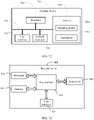
- FIG 12 is a block diagram of a terminal device according to another embodiment of this application.
- the terminal device 700 includes: at least one processor 701, a memory 702, at least one network interface 704, and a user interface 703.
- the components in the terminal device 700 are coupled together through a bus system 705.
- the bus system 705 is used to implement connection and communication between these components.
- the bus system 705 also includes a power bus, a control bus, and a status signal bus. However, for clarity of description, various buses are marked as the bus system 705 in FIG. 12 .
- the user interface 703 may include a display, a keyboard, or a clicking device, for example, a mouse, a trackball, a touch panel, or a touchscreen.
- the memory 702 in this embodiment of this application may be a volatile memory or a nonvolatile memory, or may include both a volatile memory and a nonvolatile memory.
- the nonvolatile memory may be a read-only memory (Read-Only Memory, ROM), a programmable read-only memory (Programmable ROM, PROM), an erasable programmable read-only memory (Erasable PROM, EPROM), an electrically erasable programmable read-only memory (Electrically EPROM, EEPROM), or a flash memory.
- the volatile memory may be a random access memory (Random Access Memory, RAM), and is used as an external cache.
- RAMs may be used, for example, a static random access memory (Static RAM, SRAM), a dynamic random access memory (Dynamic RAM, DRAM), a synchronous dynamic random access memory (Synchronous DRAM, SDRAM), a double data rate synchronous dynamic random access memory (Double Data Rate SDRAM, DDRSDRAM), an enhanced synchronous dynamic random access memory (Enhanced SDRAM, ESDRAM), a synchlink dynamic random access memory (Synchlink DRAM, SLDRAM), and a direct rambus random access memory (Direct Rambus RAM, DRRAM).
- Static RAM, SRAM static random access memory
- DRAM dynamic random access memory
- DRAM synchronous dynamic random access memory
- SDRAM double data rate synchronous dynamic random access memory
- Double Data Rate SDRAM DDRSDRAM
- Enhanced SDRAM ESDRAM
- Synchlink DRAM synchlink dynamic random access memory
- SLDRAM direct rambus random access memory
- Direct Rambus RAM Direct Rambus RAM
- the memory 702 stores the following elements: an operating system 7021 and an application 7022, an executable module or a data structure, or a subset thereof, or an extension set thereof.
- the operating system 7021 includes various system programs, for example, a framework layer, a kernel library layer, and a driver layer.
- the operating system 7021 is configured to implement various basic services and process hardware-based tasks.
- the application 7022 includes various applications, for example, a media player (Media Player) and a browser (Browser), and is configured to implement various application services.
- a program for implementing the method in this embodiment of this application may be included in the application 7022.
- the terminal device 700 further includes a computer program stored in the memory 702 and executable on the processor 701.
- the terminal device in the inactive-time of the connected mode discontinuous reception DRX can perform at least one operation of the beam failure detection and the radio link failure detection.
- a problem that a terminal device in an inactive-time of connected mode DXR cannot perform beam failure or radio link failure detection in an existing solution can be solved, so that the beam failure detection and the radio link failure detection are not affected by a WUS decoding result or a connected mode DRX configuration, and link status tracking performance can be ensured, that is, a beam failure and/or a radio link failure can be monitored in a timely and accurate manner, and power consumption of the terminal device can be reduced.
- the terminal device makes related preparations for beam recovery or radio link re-establishment in advance when the On duration of the DRX is about to wake up, so as to prevent the terminal device from affecting data receiving efficiency due to a delay of determining a resource for beam recovery or radio link re-establishment after the terminal device wakes up to enter the On duration of the DRX.
- the signal quality of the physical layer or the RRC layer can be monitored before the WUS is detected, and whether to detect the WUS can be determined based on the determining result of whether the signal quality monitoring result meets the target trigger event. In this way, power consumption of WUS detection can be reduced, thereby reducing power consumption of the terminal device.
- the method disclosed in the foregoing embodiments of this application may be applied to the processor 701, or implemented by the processor 701.
- the processor 701 may be an integrated circuit chip having a signal processing capability. In an implementation process, the steps of the foregoing method may be completed by using a hardware integrated logic circuit in the processor 701 or an instruction in a form of software in the processor 710.
- the processor 701 may be a general-purpose processor, a digital signal processor (Digital Signal Processor, DSP), an application-specific integrated circuit (Application-Specific Integrated Circuit, ASIC), a field programmable gate array (Field Programmable Gate Array, FPGA) or another programmable logic device, a discrete gate or transistor logic device, or a discrete hardware component.
- DSP Digital Signal Processor
- ASIC Application-Specific Integrated Circuit
- FPGA Field Programmable Gate Array
- the general purpose processor may be a microprocessor, or the processor may be any conventional processor, or the like. Steps of the methods disclosed with reference to the embodiments of this application may be directly executed and accomplished by means of a hardware decoding processor, or may be executed and accomplished by using a combination of hardware and software modules in a decoding processor.
- a software module may be located in a mature computer-readable storage medium in the art, such as a random access memory, a flash memory, a read-only memory, a programmable read-only memory, an electrically erasable programmable memory, a register, or the like.
- the computer readable storage medium is located in the memory 702, and the processor 701 reads information from the memory 702 and completes the steps of the foregoing method in combination with hardware of the processor.
- the computer-readable storage medium stores a computer program, and when the computer program is executed by the processor 701, the steps of the foregoing link management method embodiment are implemented.
- the embodiments described in the embodiments of this application may be implemented by hardware, software, firmware, middleware, microcode, or a combination thereof.
- the processing unit may be implemented in one or more application specific integrated circuits (Application Specific Integrated Circuit, ASIC), a digital signal processor (Digital Signal Processor, DSP), a digital signal processing device (DSP Device, DSPD), a programmable logic device (Programmable Logic Device, PLD), a field-programmable gate array (Field-Programmable Gate Array, FPGA), a general-purpose processor, a controller, a microcontroller, a microprocessor, another electronic unit for implementing the functions of the present disclosure, or a combination thereof.
- ASIC Application Specific Integrated Circuit
- DSP Digital Signal Processor
- DSP Device digital signal processing device
- PLD programmable logic device
- FPGA field-programmable gate array
- a general-purpose processor a controller, a microcontroller, a microprocessor, another electronic unit for implementing the functions of the present disclosure
- technologies described in the embodiments of this application may be implemented through modules (for example, procedures or functions) that implement the functions in the embodiments of this application.
- Software code may be stored in a memory and executed by a processor.
- the memory may be implemented in the processor or outside the processor.
- the terminal device 700 can implement each process implemented by the terminal device in the foregoing embodiments. To avoid repetition, details are not described herein again.
- FIG. 13 is a structural diagram of a network device applied in an embodiment of this application.
- the network device can implement the details of the foregoing link management method and achieve a same effect.
- the network device 800 includes a processor 801, a transceiver 802, a memory 803, a user interface 804, and a bus interface 805.
- the network device 800 further includes a computer program stored in the memory 803 and executable on the processor 801.
- the computer program When the computer program is executed by the processor 801, the following steps are implemented: sending transmission configuration indicator TCI information to a terminal device, where the TCI information is used to indicate M TCI states of a wake-up signal WUS, and M is a positive integer.
- the terminal device is configured to: in the case that the terminal device is in an inactive-time of connected mode discontinuous reception DRX, perform a link management operation based on the M TCI states, wherein the link management operation includes at least one of a beam failure detection operation and a radio link failure detection operation.
- a bus architecture may include any quantity of interconnected buses and bridges, which are specifically connected together by various circuits of one or more processors represented by the processor 801 and a memory represented by the memory 803.
- the bus architecture may further connect various other circuits such as peripheral devices, voltage regulators, and power management circuits, which are all known in the art, and therefore, no further description is given herein.
- the bus interface 805 provides an interface.
- the transceiver 802 may be a plurality of elements, including a transmitter and a receiver, and provides a unit for communicating on a transmission medium with various other apparatuses.
- the user interface 804 may also be an interface capable of connecting externally and internally to a required device.
- the connected device includes but is not limited to a keypad, a display, a speaker, a microphone, a joystick, and the like.
- the processor 801 is responsible for managing the bus architecture and common processing, and the memory 803 may store data used when the processor 801 performs an operation.
- the transmission configuration indicator TCI information used to indicate at least one TCI state of the wake-up signal WUS is configured for the terminal device, so that when the terminal device is in the inactive-time of the connected state discontinuous reception DRX, a corresponding link management operation can be performed based on the M TCI states, and at least one operation of the beam failure detection and the radio link failure detection can be performed.
- a problem that a terminal device in an inactive-time of connected mode DXR cannot perform beam failure or radio link failure detection in an existing solution can be solved, so that the beam failure detection and the radio link failure detection are not affected by a WUS decoding result or a connected mode DRX configuration, and link status tracking performance by the terminal device can be ensured, that is, a beam failure and/or a radio link failure can be monitored in a timely and accurate manner, and power consumption of the terminal device can be reduced.
- the terminal device can monitor the beam failure and/or the radio link failure in a timely and accurate manner, this helps the terminal device make related preparations for beam recovery or radio link re-establishment in advance when the On duration of the DRX is about to wake up, so as to prevent the terminal device from affecting data receiving efficiency due to a delay of determining a resource for beam recovery or radio link re-establishment after the terminal device wakes up to enter the On duration of the DRX.
- an embodiment of this application further provides a terminal device, including a processor, a memory, a computer program stored in the memory and executable on the processor.
- a terminal device including a processor, a memory, a computer program stored in the memory and executable on the processor.
- the computer program is executed by the processor, the processes of the foregoing link management method embodiment are implemented, and a same technical effect can be achieved. To avoid repetition, details are not described herein again.
- An embodiment of this application further provides a computer-readable storage medium.
- the computer-readable storage medium stores a computer program.
- the processes of the foregoing link management method embodiment applied to the terminal device are implemented, and a same technical effect can be achieved. To avoid repetition, details are not described herein again.
- the computer-readable storage medium is, for example, a read-only memory (Read-Only Memory, ROM), a random access memory (Random Access Memory, RAM), a magnetic disk, a compact disc, or the like.
- an embodiment of this application further provides a terminal device, including a processor, a memory, a computer program stored in the memory and executable on the processor.
- a terminal device including a processor, a memory, a computer program stored in the memory and executable on the processor.
- the computer program is executed by the processor, the processes of the foregoing wake-up signal detection method embodiment are implemented, and a same technical effect can be achieved. To avoid repetition, details are not described herein again.
- An embodiment of this application further provides a computer-readable storage medium.
- the computer-readable storage medium stores a computer program.
- the computer program is executed by a processor, the processes of the foregoing wake-up signal detection method embodiment are implemented, and a same technical effect can be achieved. To avoid repetition, details are not described herein again.
- the computer-readable storage medium is, for example, a read-only memory (Read-Only Memory, ROM), a random access memory (Random Access Memory, RAM), a magnetic disk, a compact disc, or the like.
- an embodiment of this application further provides a network device, including a processor, a memory, a computer program stored in the memory and executable on the processor.
- a network device including a processor, a memory, a computer program stored in the memory and executable on the processor.
- the processes of the foregoing link management method embodiment are implemented, and a same technical effect can be achieved. To avoid repetition, details are not described herein again.
- An embodiment of this application further provides a computer-readable storage medium.
- the computer-readable storage medium stores a computer program.
- the processes of the foregoing link management method embodiment applied to the network device are implemented, and a same technical effect can be achieved. To avoid repetition, details are not described herein again.
- the computer-readable storage medium is, for example, a read-only memory (Read-Only Memory, ROM), a random access memory (Random Access Memory, RAM), a magnetic disk, a compact disc, or the like.
- the method in the foregoing embodiment may be implemented by software in addition to a necessary universal hardware platform or by hardware only. In most circumstances, the former is a preferred implementation. Based on such an understanding, the technical solutions of this application essentially, or the part contributing to the prior art may be implemented in a form of a software product.
- the computer software product is stored in a storage medium (for example, a ROM/RAM, a magnetic disk, or a compact disc), and includes a plurality of instructions for instructing a terminal (which may be a mobile phone, a computer, a server, an air conditioner, a network device, or the like) to perform the method described in the embodiments of this application.
Landscapes
- Engineering & Computer Science (AREA)
- Signal Processing (AREA)
- Computer Networks & Wireless Communication (AREA)
- Quality & Reliability (AREA)
- Physics & Mathematics (AREA)
- Electromagnetism (AREA)
- Mobile Radio Communication Systems (AREA)
Abstract
Description
- This application claims priority to
Chinese Patent Application 201910569112.1, filed on June 27, 2019 - This application relates to the field of communications, and in particular, to a link management method, wake-up signal detection method, terminal device and network device.
- Currently, in a new radio (New Radio, NR) mobile communications system (NR system for short), for a radio resource control connected state (Connected), a base station may configure discontinuous reception (Discontinuous Reception, DRX), namely, connected mode DRX (C-DRX for short), for user equipment (User Equipment, UE) based on a service characteristic of the UE, so as to reduce power consumption of the UE.
- Specifically, before an On duration (On-duration) of the C-DRX, the UE may determine whether to wake up by receiving a wake-up signal (Wake-Up Signal, WUS). However, considering that an inactive-time of the C-DRX may be relatively long, when the UE is in the inactive-time (Inactive-time), a beam failure or radio link failure may be caused due to reasons such as motion, thereby affecting data reception of the UE in the On duration of the C-DRX. However, in the inactive-time of the C-DRX, currently the UE cannot monitor whether a beam or radio link fails.
- One of the technical problems solved by embodiments of this application is that a terminal device in an inactive-time of connected mode discontinuous reception DRX cannot monitor whether a beam or radio link fails.
- According to a first aspect, an embodiment of this application provides a link management method, applied to a terminal device. The method includes:
- receiving transmission configuration indicator (Transmission Configuration Indicator, TCI) information, where the TCI information is used to indicate M TCI states of a wake-up signal WUS, and M is a positive integer; and
- in the case that the terminal device is in an inactive-time of connected mode discontinuous reception DRX, performing a link management operation based on the M TCI states, where the link management operation includes at least one of a beam failure detection operation and a radio link failure detection operation.
- According to a second aspect, an embodiment of this application provides a terminal device. The terminal device includes:
- a receiving module, configured to receive transmission configuration indicator TCI information, where the TCI information is used to indicate M TCI states of a wake-up signal WUS, and M is a positive integer; and
- a management module, configured to: in the case that the terminal device is in an inactive-time of connected mode discontinuous reception DRX, perform a link management operation based on the M TCI states, where the link management operation includes at least one of a beam failure detection operation and a radio link failure detection operation.
- According to a third aspect, an embodiment of this application provides a terminal device, including a memory, a processor, and a computer program stored in the memory and executable on the processor. When the computer program is executed by the processor, the steps of the method according to the first aspect are implemented.
- According to a fourth aspect, an embodiment of this application provides a computer-readable storage medium. The computer-readable storage medium stores a computer program, and when the computer program is executed by a processor, the steps of the method according to the first aspect are implemented.
- According to a fifth aspect, an embodiment of this application provides a wake-up signal detection method, applied to a terminal device. The method includes:
- monitoring signal quality corresponding to a physical layer or a radio resource control (Radio Resource Control, RRC) layer of the terminal device; and
- determining whether to detect a wake-up signal WUS based on a determining result of whether a signal quality monitoring result meets a target trigger event, where
- the target trigger condition includes one of the following:
- the physical layer of the terminal device reports an out-of-synchronization indication to the RRC layer, and a first timer is started;
- a number counted by a beam failure counter of a media access control (Medium Access Control, MAC) layer of the terminal device is greater than or equal to a preset number of times;
- a reference signal received power (Reference Signal Received Power, RSRP) is continuously less than a first threshold within a first time period, where the first threshold is configured by a network device or determined based on a first preset condition;
- a target channel quality parameter is continuously less than a second threshold within a first time period, where the target channel quality parameter includes a signal-to-interference-plus-noise ratio (Signal-to-Noise-plus-Interference Ratio, SINR) or a channel quality indicator (Channel Quality Indicator, CQI), and the second threshold is configured by a network device or determined based on a second preset condition;
- reference signal received quality (Reference Signal Received Quality, RSRQ) is less than a third threshold; or
- a block error rate (Block Error Rate, BLER) is greater than a third rate.
- According to a sixth aspect, an embodiment of this application provides a terminal device. The terminal device includes:
- a monitoring module, configured to monitor signal quality corresponding to a physical layer or a radio resource control RRC layer of the terminal device; and
- a detection module, configured to determine whether to detect a wake-up signal WUS based on a determining result of whether a signal quality monitoring result meets a target trigger event, where
- the target trigger condition includes one of the following:
- the physical layer of the terminal device reports an out-of-synchronization indication to the RRC layer, and a first timer is started;
- a number counted by a beam failure counter of a media access control MAC layer of the terminal device is greater than or equal to a preset number of times;
- a reference signal received power RSRP is continuously less than a first threshold within a first time period, where the first threshold is configured by a network device or determined based on a first preset condition;
- a target channel quality parameter is continuously less than a second threshold within a first time period, where the target channel quality parameter includes a signal-to-interference-plus-noise ratio SINR or a channel quality indicator CQI, and the second threshold is configured by a network device or determined based on a second preset condition;
- reference signal received quality RSRQ is less than a third threshold; or
- a block error rate BLER is greater than a third rate.
- According to a seventh aspect, an embodiment of this application provides a terminal device, including a memory, a processor, and a computer program stored in the memory and executable on the processor. When the computer program is executed by the processor, the steps of the method according to the fifth aspect are implemented.
- According to an eighth aspect, an embodiment of this application provides a computer-readable storage medium. The computer-readable storage medium stores a computer program, and when the computer program is executed by a processor, the steps of the method according to the fifth aspect are implemented.
- According to a ninth aspect, an embodiment of this application provides a link management method, applied to a network device. The method includes:
- sending transmission configuration indicator TCI information to a terminal device, where the TCI information is used to indicate M TCI states of a wake-up signal WUS, and M is a positive integer, where
- the terminal device is configured to: in the case that the terminal device is in an inactive-time of connected mode discontinuous reception DRX, perform a link management operation based on the M TCI states, where the link management operation includes at least one of a beam failure detection operation and a radio link failure detection operation.
- According to a tenth aspect, an embodiment of this application provides a network device. The Network device includes:
a sending module, configured to send transmission configuration indicator TCI information to a terminal device, where the TCI information is used to indicate M TCI states of a wake-up signal WUS, and M is a positive integer. - The terminal device is configured to: in the case that the terminal device is in an inactive-time of connected mode discontinuous reception DRX, perform a link management operation based on the M TCI states, where the link management operation includes at least one of a beam failure detection operation and a radio link failure detection operation.
- According to an eleventh aspect, an embodiment of this application provides a network device, including a memory, a processor, and a computer program stored in the memory and executable on the processor. When the computer program is executed by the processor, the steps of the method according to the ninth aspect are implemented.
- According to a twelfth aspect, an embodiment of this application provides a computer-readable storage medium. The computer-readable storage medium stores a computer program, and when the computer program is executed by a processor, the steps of the method according to the ninth aspect are implemented.
- In the embodiments of this application, in the case that the network device has configured transmission configuration indicator TCI information used to indicate at least one TCI state of a wake-up signal WUS, when performing a corresponding link management operation based on the M TCI states, the terminal device in the inactive-time of the connected mode discontinuous reception DRX can perform at least one operation of the beam failure detection and the radio link failure detection.
- In this way, a problem that a terminal device in an inactive-time of connected mode DXR cannot perform beam failure or radio link failure detection in an existing solution can be solved, so that the beam failure detection and the radio link failure detection are not affected by a WUS decoding result or a connected mode DRX configuration, and link status tracking performance can be ensured, that is, a beam failure and/or a radio link failure can be monitored in a timely and accurate manner, and power consumption of the terminal device can be reduced. Further, because the beam failure and/or the radio link failure can be monitored in a timely and accurate manner, this helps the terminal device make related preparations for beam recovery or radio link re-establishment in advance when the On duration of the DRX is about to wake up, so as to prevent the terminal device from affecting data receiving efficiency due to a delay of determining a resource for beam recovery or radio link re-establishment after the terminal device wakes up to enter the On duration of the DRX.
- Characteristics, advantages, and technical effects of embodiments of this application are described below with reference to the accompanying drawings.
-
FIG 1 is a schematic flowchart of a first link management method according to an embodiment of this application; -
FIG. 2 is a schematic diagram of a first configuration of a WUS periodicity and offset according to an embodiment of this application; -
FIG. 3 is a schematic diagram of a second configuration of a WUS periodicity and offset according to an embodiment of this application; -
FIG. 4 is a schematic diagram of a first configuration of M target reference signals according to an embodiment of this application; -
FIG. 5 is a schematic diagram of a second configuration of M target reference signals according to an embodiment of this application; -
FIG. 6 is a schematic diagram of a third configuration of M target reference signals according to an embodiment of this application; -
FIG. 7 is a schematic flowchart of a wake-up signal detection method according to an embodiment of this application; -
FIG. 8 is a schematic flowchart of a second link management method according to an embodiment of this application; -
FIG. 9 is a schematic structural diagram of a terminal device according to an embodiment of this application; -
FIG. 10 is a schematic structural diagram of a second terminal device according to an embodiment of this application; -
FIG. 11 is a schematic structural diagram of a network device according to an embodiment of this application; -
FIG. 12 is a schematic structural diagram of a third terminal device according to an embodiment of this application; and -
FIG. 13 is a schematic structural diagram of a second network device according to an embodiment of this application. - The following further describes implementations of this application in detail with reference to the accompanying drawings and embodiments. The detailed description of the following embodiments and the accompanying drawings are used as examples to describe principles of this application, but shall not be used to limit the scope of this application. In other words, this application is not limited to the described embodiments.
- The following describes in detail the technical solutions provided in the embodiments of this application with reference to the accompanying drawings.
- As shown in
FIG. 1 , an embodiment of this application provides a link management method, which is performed by a terminal device. The method may include the following content: - Step 101: Receive transmission configuration indicator TCI information, where the TCI information is used to indicate M TCI states of a wake-up signal WUS, and M is a positive integer.
- It can be understood that M is an integer greater than or equal to 1.
- Step 103: In the case that the terminal device is in an inactive-time of connected mode discontinuous reception DRX, perform a link management operation based on the M TCI states, where the link management operation includes at least one of a beam failure detection operation and a radio link failure detection operation.
- In this embodiment, in the case that a network device has configured transmission configuration indicator TCI information used to indicate at least one TCI state of a wake-up signal WUS, when performing a corresponding link management operation based on the M TCI states, the terminal device in the inactive-time of the connected mode discontinuous reception DRX can perform at least one operation of the beam failure detection and the radio link failure detection. In this way, a problem that a terminal device in an inactive-time of connected mode DXR cannot perform beam failure or radio link failure detection in an existing solution can be solved, so that the beam failure detection and the radio link failure detection are not affected by a WUS decoding result or a connected mode DRX configuration, and link status tracking performance can be ensured, that is, a beam failure and/or a radio link failure can be monitored in a timely and accurate manner, and power consumption of the terminal device can be reduced. Further, because the beam failure and/or the radio link failure can be monitored in a timely and accurate manner, this helps the terminal device make related preparations for beam recovery or radio link re-establishment in advance, for example, determine in advance a beam meeting a beam recovery condition, when the On duration of the DRX is about to wake up, so as to prevent the terminal device from affecting data receiving efficiency due to a delay of determining a resource used for beam recovery or radio link re-establishment after the terminal device wakes up to enter the On duration of the DRX.
- It can be understood that for the terminal device, in the case of a plurality of M TCI states, the network device sends a same WUS based on any two TCI states of the M TCI states, that is, in the case that the WUS is successfully decoded, decoding results of instructing the terminal device by the network device to stay in the inactive-time of the DRX or to enter the On duration of the DRX from the inactive-time of the DRX are the same. In other words, the terminal device considers that all WUSs sent by the network device based on the M TCI states carry same wake-up or sleep messages. In addition, reliability of WUS receiving can be improved with the help of the plurality of TCI states.
- Optionally, in the link management method in this embodiment of this application, there may be different configuration schemes for the M TCI states, so that the terminal device detects, with a diversity of schemes, WUSs based on beams corresponding to the M TCI states.
- In a specific embodiment, any two TCI states of the M TCI states correspond to a same control resource set (Control Resource Set, CORESET) configuration, a same search space (Search Space, SS) configuration, and different slot-related configurations.
- It can be understood that, in the case of a plurality of M TCI states, any two TCI states of the plurality of TCI states may have a same CORESET configuration and a same SS configuration, but each TCI state of the plurality of TCI states may have a dedicated slot-related configuration, that is, slot-related configurations of any two TCI states are different. To be specific, there is one SS for one CORESET, a plurality of different slot-related configurations are configured for the SS, and one slot-related configuration corresponds to one TCI state.
- In another specific embodiment, any two TCI states of the M TCI states correspond to a same CORESET configuration and different SS configurations, and each SS configuration has a separate slot-related configuration.
- It can be understood that, in the case of a plurality of M TCI states, any two TCI states of the plurality of TCI states may have a same CORESET configuration and different SS configurations. Specifically, each SS configuration of M SS configurations corresponding to the M TCI states may have a separate dedicated slot-related configuration. To be specific, there is a plurality of SSs for one CORESET, one slot-related configuration is correspondingly configured for each SS, and one slot-related configuration corresponds to one TCI state.
- Optionally, in one aspect, the slot-related configuration may include a slot-level periodicity configuration and a slot offset configuration; to be specific, slot-level periodicity configurations and slot offset configurations corresponding to any two TCI states or any two SS configurations are different. In another aspect, the slot-related configuration may include a slot-level periodicity configuration, a slot offset configuration, and an in-slot symbol offset configuration; to be specific, slot-level periodicity configurations, slot offset configurations, and in-slot symbol offset configurations corresponding to any two TCI states or any two SS configurations are different.
- For example, as shown in
FIG. 2 , QCL1 and QCL2 shown in the figure mean two TCI states. The two TCI states have a same CORESET configuration and a same SS configuration, but the two TCI states respectively have dedicated slot-level periods Periodicity T1_WUS and Periodicity T2_WUS, different slot offsets Slot offset O1_WUS and Slot offset O2_WUS, and different in-slot symbol offsets Symbol offset o1_WUS and Symbol offset o2_WUS. - As shown in
FIG. 3 , QCL1 and QCL2 shown in the figure mean two TCI states. The two TCI states have a same CORESET configuration and different SS configurations, and the two SS configurations respectively have dedicated slot-level periods Periodicity T_WUS1 and PeriodicityT_WUS2, different slot offsets Slot offset O_WUS1 and Slot offset O_WUS2, and different in-slot symbol offsets Symbol offset o_WUS1 and Symbol offset o_WUS2. - Further, optionally, WUS sending moments corresponding to the M TCI states are concentrated in a period less than or equal to a preset time length.
- It can be understood that, by means of the slot-related configurations corresponding to the M TCI states, the WUS sending moments corresponding to the M TCI states are concentrated in a period less than or equal to the preset time length. In this way, it can be ensured that the WUS sending moments are kept within a range that is convenient for receiving by the terminal device. For example, WUS sending moments corresponding to all M TCI states are concentrated in a range of 5 ms, which certainly may be another value.
- Optionally, in the link management method in this embodiment of this application, a value of M is less than or equal to a total number of reference signals in a universe of beam recovery reference signals or a universe of radio link monitoring reference signals corresponding to the M TCI states.
- It can be understood that, in order to help the terminal device implement a related link management operation, the network device configures the universe of beam recovery reference signals or the universe of radio link monitoring reference signals accordingly, and indicates, for the WUS through the TCI information, to use M reference signals in the universe as the reference signals corresponding to the M TCI states. In other words, the M reference signals constitute a subset of the universe, and a total number of reference signals in the subset is less than or equal to the total number of reference signals in the universe.
- Optionally, in the link management method in this embodiment of this application, the foregoing
step 103 may be implemented as different specific embodiments. - In a specific embodiment, optionally, the foregoing
step 103 may be performed as the following content: - monitoring signal quality of a reference signal related to the WUS; and
- if a signal quality monitoring result meets a target trigger event, performing a link management operation related to the target trigger event.
- In this specific embodiment, upon a monitored result of the signal quality of the reference signal related to the WUS, that is, based on determining whether the signal quality monitoring result meets the target trigger event, when it is determined that the signal quality monitoring result meets a condition, the terminal device can be directly woken up to perform a link management operation related to the specific target trigger event. In this way, without considering the WUS decoding result, specific indication content of the decoding result, or whether the On duration of the DRX has arrived, the terminal device can skip performing WUS decoding when the signal quality monitoring result meets the target trigger event, to directly enter the On duration of the DRX to implement a corresponding link management operation, such as a beam recovery operation or a radio link re-establishment operation, thereby improving link management efficiency and meanwhile reducing WUS decoding overheads.
- Further, in this specific embodiment, the link management method in this embodiment of this application further includes:
- if the signal quality monitoring result does not meet the target trigger event, decoding the WUS detected based on the M TCI states; and
- in the case that the WUS is successfully decoded and a decoding result indicates to enter the On duration of the DRX, performing an operation of entering the On duration; or
- in the case that the WUS is successfully decoded and a decoding result indicates to stay in the inactive-time, performing an operation of continuing to stay in the inactive-time.
- It can be understood that, for the determining whether the signal quality monitoring result meets the target trigger event, if it is determined that the signal quality monitoring result does not meet the condition, the WUS needs to be decoded first, and in the case of successful decoding, a corresponding operation is performed based on the specific indication content of the decoding result. To be specific, in the case that the WUS decoding result indicates to wake up the terminal device, the terminal device is immediately woken up to enter the On duration of the DRX for data receiving, without waiting for the On duration of the DRX to arrive; otherwise, in the case that the decoding result indicates to stay in the inactive-time, the terminal device continues to stay in the inactive-time of the DRX to enter a next round of an operation of monitoring the signal quality of the reference signal related to the WUS, until determining of whether to wake up the terminal device to perform a corresponding link management operation based on a result of determining whether a corresponding signal quality monitoring result meets the target trigger event.
- In another specific embodiment, optionally, the foregoing
step 103 may be performed as the following content: - decoding the WUS detected based on the M TCI states;
- in the case that the WUS is successfully decoded and a decoding result indicates to stay in the inactive-time, monitoring signal quality of a reference signal related to the WUS; and
- if a signal quality monitoring result meets a target trigger event, performing a link management operation related to the target trigger event.
- It can be understood that, in this specific embodiment, the WUS detected based on the M TCI states may be decoded first, and then whether the signal quality of the reference signal related to the WUS needs to be monitored is further determined based on the decoding result obtained after successful decoding. Specifically, in the case that the signal quality monitoring result meets the target trigger event, a corresponding link management operation is performed. In other words, without waking up the terminal device temporarily, a corresponding link management operation can still be performed based on the signal quality monitoring result of the reference signal related to the WUS, which is not affected by the terminal device still in the inactive-time of the DRX.
- It should be noted that if the WUS decoding result indicates to enter the On duration of the DRX, the terminal device can be directly woken up to enter the On duration for data receiving.
- Optionally, the operation of monitoring the signal quality of the reference signal related to the WUS in any one of the foregoing specific embodiments may be implemented based on different reference signals, and the details are as follows:
- In a specific embodiment, optionally, the reference signal related to the WUS includes a demodulation reference signal (Demodulation Reference Signal, DMRS) in a CORESET corresponding to the M TCI states, and the DMRS is quasi co-located with a synchronization signal block (Synchronization Signal Block, SSB) or a channel state information (Channel State Information, CSI) reference signal used to represent broadband beam information.
- Further, the step of monitoring signal quality of a reference signal related to the WUS may be specifically implemented as:
monitoring the signal quality on a bandwidth part (Bandwidth Part, BWP) corresponding to the WUS. - It can be understood that the signal quality monitoring can be implemented with the help of the DMRS in the CORESET corresponding to the M TCI states of the WUS. In other words, the terminal device can monitor the WUS on the CORESET corresponding to the M different TCI states, and further the signal quality corresponding to the beam carrying the WUS can be obtained by using the DMRS in the CORESET. Specifically, in the case that the network device has configured a dedicated bandwidth part BWP for the WUS, the signal quality of the reference signal related to the WUS can be monitored on the BWP. Therefore, in the case that the signal quality monitoring result meets the target trigger event, a link management operation related to the target trigger event can be performed.
- The signal quality result monitored on the BWP can be converted into a BLER for physical downlink control channel (Physical Downlink Control Channel, PDCCH) receiving on a full bandwidth, and further whether to perform a related link management event is determined based on a result of whether the BLER meets the target trigger event. The DMRS needs to be consistent with the SSB or CSI reference signal used to represent the broadband beam information, that is, the DMRS has a QCL-type D and QCL-type A quasi co-location relationship with the SSB or CSI-RS. In this way, the terminal device can be woken up more shallowly, so that more registers, clocks, and the like on a chip of the terminal device are in a sleep state, thereby further reducing power consumption of the terminal device.
- It should be noted that, in a specific embodiment in which the reference signal related to the WUS is a DMRS in the CORESET corresponding to the M TCI states, the target trigger event may include one of the following:
- (1) A physical layer of the terminal device reports an out-of-synchronization indication to a radio resource control RRC layer, and a first timer is started.
- (2) A number counted by a beam failure counter of a media access control MAC layer of the terminal device is greater than or equal to a preset number of times.
- (3) A reference signal received power RSRP is continuously less than a first threshold within a first time period, where the first threshold is configured by a network device or determined based on a first preset condition.
It can be understood that the first threshold used as an assessment criterion of the reference signal received power RSRP may be implicitly determined based on the first preset condition. Specifically, the first preset condition may include: a BLER is greater than a specified rate. - (4) A target channel quality parameter is continuously less than a second threshold within a first time period, where the target channel quality parameter includes a signal-to-interference-plus-noise ratio SINR or a channel quality indicator CQI, and the second threshold is configured by a network device or determined based on a second preset condition.
It can be understood that the second threshold used as an assessment criterion of the target channel quality parameter may be implicitly determined based on the second preset condition. Specifically, the second preset condition may include: a BLER is greater than a specified rate. - (5) Reference signal received quality RSRQ is less than a third threshold.
- (6) A block error rate BLER is greater than a third rate.
- It should be noted that corresponding link management operations can be respectively performed for the foregoing target trigger events, for example:
- For the foregoing trigger event (1), when the signal quality monitoring result indicates that link quality is continuously lower than a particular specified threshold, the physical layer of the terminal device reports an out-of-synchronization (Out-Of-Sync, OOS) indication to the RRC layer, and when the RRC layer is triggered to start the first timer (namely, T310 timer), it can be considered that the signal quality monitoring result meets the target trigger event. Further, based on this, the radio link failure detection operation can be performed, and further, after a radio link failure is detected, for example after the terminal device finds that there are not sufficient in-synchronization (In-Sync, IS) indications for reporting before the first timer expires, the radio link re-establishment operation can be performed. In other words, in addition to the radio link failure detection operation, the link management operation further includes the radio link re-establishment operation.
- For the foregoing trigger event (2), when the signal quality monitoring result indicates that link quality is continuously lower than a particular specified threshold, the physical layer of the terminal device reports a beam failure to a MAC layer. To be specific, when the beam failure detection operation is performed based on the signal quality monitoring result and a beam failure is determined, the physical layer reports to the MAC layer to trigger the MAC layer to start a beam failure timer (BeamFailureDetectionTimer). Before the beam failure timer expires, each time the physical layer reports a beam failure to the MAC layer, a count value of a beam failure counter (namely, a register BFI_COUNTER) increases by 1. Further, if the count value of the register has not reached a preset count BeamFailureInstanceMaxCount before the beam failure timer expires, the count value of the register is reset; if the count value of the register is greater than or equal to the preset count when the beam failure timer expires, a beam recovery process can be started. In other words, in addition to the beam failure detection operation, the link management operation further includes the beam recovery operation.
- For the foregoing trigger events (3) to (6), when the signal quality monitoring result includes the RSRP, the target channel quality parameter, which is the SINR or CQI, the RSRQ, or the BLER, the beam failure detection operation and/or the radio link failure detection operation can be performed based on a monitoring result of the foregoing parameter. Further, a beam failure recovery operation can be performed after a beam failure is detected, and/or a radio link re-establishment operation can be performed after a radio link failure is detected. Further, after the terminal device wakes up to enter the On duration of the DRX, the DMRS in the CORESET corresponding to the M TCI states can no longer be used to monitor link signal quality, that is, a normal beam status and/or radio link status monitoring process can be restored.
- It should be noted that, in other specific embodiments of this application, in addition to the DMRS, the reference signal related to the WUS may be another reference signal RS that is quasi co-located (Quasi Co-Location, QCL) with the WUS.
- In another specific embodiment, optionally, the reference signal related to the WUS includes M target reference signals corresponding to the M TCI states, and the M target reference signals are quasi co-located with the WUS.
- Further, each target reference signal of the M target reference signals may include one of the following:
- one of a beam failure detection reference signal (Beam Failure Detection RS, BFD-RS) and a radio link monitoring reference signal (Radio Link Monitoring RS, RLM-RS); or
- another reference signal that is quasi co-located with the BFD-RS or the RLM-RS.
- Optionally, as shown
FIG. 4 , each target reference signal includes the BFD-RS and the RLM-RS. - Further, the step of monitoring signal quality of a reference signal related to the WUS may be specifically implemented as: monitoring signal quality of the M target reference signals.
- Optionally, in a specific embodiment in which the reference signal related to the WUS is the M target reference signals, and each target reference signal does not include a beam failure recovery reference signal (Beam Failure Recovery RS, BFR-RS), the foregoing target trigger event may include one of the following:
- (1) A physical layer of the terminal device reports an out-of-synchronization indication to a radio resource control RRC layer, and a first timer is started.
- (2) A number counted by a beam failure counter of a media access control MAC layer of the terminal device is greater than or equal to a preset number of times.
- (3) A reference signal received power RSRP is continuously less than a first threshold within a first time period, where the first threshold is configured by a network device or determined based on a first preset condition.
It can be understood that the first threshold used as an assessment criterion of the reference signal received power RSRP may be implicitly determined based on the first preset condition. Specifically, the first preset condition may include: a BLER is greater than a specified rate. - (4) A target channel quality parameter is continuously less than a second threshold within a first time period, where the target channel quality parameter includes a signal-to-interference-plus-noise ratio SINR or a channel quality indicator CQI, and the second threshold is configured by a network device or determined based on a second preset condition.
It can be understood that the second threshold used as an assessment criterion of the target channel quality parameter may be implicitly determined based on the second preset condition. Specifically, the second preset condition may include: a BLER is greater than a specified rate. - (5) Reference signal received quality RSRQ is less than a third threshold.
- (6) A block error rate BLER is greater than a third rate.
- It should be noted that corresponding link management operations can be respectively performed for the foregoing target trigger events, for example:
For the foregoing trigger event (1), when the signal quality monitoring result indicates that link quality is continuously lower than a particular specified threshold, the physical layer of the terminal device reports an OOS indication to the RRC layer, and when the RRC layer is triggered to start the first timer (namely, T310 timer), it can be considered that the signal quality monitoring result meets the target trigger event. Further, based on this, the radio link failure detection operation can be performed, and further, after a radio link failure is detected, for example after the terminal device finds that there are not sufficient IS indications for reporting before the first timer expires, the radio link re-establishment operation can be performed. In other words, in addition to the radio link failure detection operation, the link management operation further includes the radio link re-establishment operation. - For the foregoing trigger event (2), when the signal quality monitoring result indicates that link quality is continuously lower than a particular specified threshold, the physical layer of the terminal device reports a beam failure to a MAC layer. To be specific, when the beam failure detection operation is performed based on the signal quality monitoring result and a beam failure is determined, the physical layer reports to the MAC layer to trigger the MAC layer to start a beam failure timer (namely, BeamFailureDetectionTimer). Before the beam failure timer expires, each time the physical layer reports a beam failure to the MAC layer, a count value of a beam failure counter (namely, a register BFI_COUNTER) increases by 1. Further, if the count value of the register has not reached a preset count BeamFailureInstanceMaxCount before the beam failure timer expires, the count value of the register is reset. If the count value of the register is greater than or equal to the preset count when the beam failure timer expires, a beam recovery process can be started. In other words, in addition to the beam failure detection operation, the link management operation further includes the beam recovery operation.
- For the foregoing trigger events (3) to (6), when the signal quality monitoring result includes the RSRP, the target channel quality parameter, which is the SINR or CQI, the RSRQ, or the BLER, the beam failure detection operation and/or the radio link failure detection operation can be performed based on a monitoring result of the foregoing parameter. Further, a beam failure recovery operation can be performed after a beam failure is detected, and/or a radio link re-establishment operation can be performed after a radio link failure is detected. Further, after the terminal device wakes up to enter the On duration of the DRX, the DMRS in the CORESET corresponding to the M TCI states can no longer be used to monitor link signal quality, that is, a normal beam status and/or radio link status monitoring process can be restored.
- In still another specific embodiment, optionally, the reference signal related to the WUS includes M target reference signals corresponding to the M TCI states, and the M target reference signals are quasi co-located with the WUS.
- Further, each target reference signal of the M target reference signals may include one of the following:
- a BFD-RS and a beam failure recovery reference signal BFR-RS;
- the BFD-RS, the BFR-RS, and an RLM-RS; or
- another reference signal that is quasi co-located with the BFD-RS, the RLM-RS, or the BFR-RS.
- Optionally, as shown
FIG. 5 , each target reference signal includes the BFD-RS and the BFR-RS; as shown inFIG. 6 , each target reference signal includes the BFD-RS, the BFR-RS, and the RLM-RS. - Further, the step of monitoring signal quality of a reference signal related to the WUS may be specifically implemented as: monitoring signal quality of the M target reference signals.
- Optionally, in a specific embodiment in which the reference signal related to the WUS is the M target reference signals, and each target reference signal includes a BFR-RS, the foregoing target trigger event may include one of the following:
- (1) A reference signal received power RSRP is continuously less than a first threshold within a first time period, where the first threshold is configured by a network device or determined based on a first preset condition.
It can be understood that the first threshold used as an assessment criterion of the reference signal received power RSRP may be implicitly determined based on the first preset condition. Specifically, the first preset condition may include: a BLER is greater than a specified rate. - (2) A target channel quality parameter is continuously less than a second threshold within a first time period, where the target channel quality parameter includes a signal-to-interference-plus-noise ratio SINR or a channel quality indicator CQI, and the second threshold is configured by a network device or determined based on a second preset condition.
It can be understood that the second threshold used as an assessment criterion of the target channel quality parameter may be implicitly determined based on the second preset condition. Specifically, the second preset condition may include: a BLER is greater than a specified rate. - (3) Reference signal received quality RSRQ is less than a third threshold.
- (4) A block error rate BLER is greater than a third rate.
- It should be noted that corresponding link management operations can be respectively performed for the foregoing target trigger events, for example:
- When the signal quality monitoring result includes the RSRP, the target channel quality parameter, which is the SINR or CQI, the RSRQ, or the BLER, the beam failure detection operation and/or the radio link failure detection operation can be performed based on a monitoring result of the foregoing parameter. Further, a beam failure recovery operation can be performed after a beam failure is detected, and/or a radio link re-establishment operation can be performed after a radio link failure is detected.
- It should be noted that in the case that the reference signal related to the WUS is the BFD-RS and the RLM-RS, that is, in the case that the WUS is sent based on beams corresponding to the BFD-RS and the RLM-RS, if there are a BFR-RS and an RLM-RS sent based on a same time-frequency resource, that is, if in-symbol time-frequency domain positions, periodicities, and offsets are the same, in the configuration manner shown in
FIG. 2 , periodicity and symbol offset configurations in a recovery SS are invalid, and the recovery SS uses a configuration of the WUS for execution; in addition, in the configuration manner shown inFIG. 3 , an SS WUS2 may no longer be additionally configured, and instead, the periodicity and symbol offset configurations in the recovery SS are used. - Values of the foregoing preset thresholds, time periods, rates, numbers of times, and the like may be set according to actual link management requirements.
- Furthermore, it should be noted that, in the case that the network device has configured the BFR-RS for the terminal device, when performing a beam recovery operation, the terminal device may determine a beam meeting the beam recovery condition based on the BFR-RS, a reference signal that is quasi co-located with the BFR-RS, or a DMRS in a CORESET corresponding to a target TCI state. The target TCI state is a TCI state, corresponding to the BFR-RS, of the M TCI states. For each TCI state with a same CORESET configuration, the CORESET is consistent with a CORESET in a recovery SS configured in a BFR configuration. An SS configuration of each TCI state other than a TCI state consistent with a PDCCH in the On duration reuses a beam recovery SS configured in the BFR configuration. If no BFR-RS is configured, a beam meeting the beam recovery condition can be determined from a candidate beam set. Specifically, the candidate recovery beam set is determined based on an identifier of a demodulation reference signal DMRS in a CORESET configuration, SS configuration, or SS periodicity configuration other than a CORESET configuration and SS configuration corresponding to the M TCI states, and the identifier is configured by a network device through an RRC message.
- Optionally, in the link management method in this embodiment of this application, if the network device has configured the candidate recovery beam set for the terminal device, the foregoing
step 103 may be further implemented as the following operation: - decoding the WUS detected based on the M TCI states;
- in the case that the WUS is successfully decoded, a decoding result indicates to stay in the inactive-time, and there is a candidate recovery beam set meeting a beam recovery condition, if a beam failure is determined through the beam failure detection, skipping performing a beam recovery operation; or
- in the case that the WUS fails to be decoded or the WUS is successfully decoded and a decoding result indicates to enter an On duration of the DRX, if a beam failure is determined through the beam failure detection, performing a beam recovery operation based on the candidate recovery beam set meeting the beam recovery condition.
- It can be understood that, in order to further reduce power consumption of the terminal device, in the case that the WUS is successfully decoded, a decoding result indicates to stay in the inactive-time, and there is a candidate recovery beam set meeting the beam recovery condition, if a beam failure is determined based on a result of the beam failure detection operation, the beam recovery operation may be skipped temporarily. In this way, when there is no service for the terminal device, frequent wake-up caused by link state changes is avoided, thereby effectively reducing power consumption of the terminal device. In addition, when the WUS fails to be decoded, or the WUS is successful decoded, a decoding result indicates to enter the On duration, and an existing beam failure flag is found, an available beam can be found from the candidate recovery beam set meeting the beam recovery condition, to perform beam recovery. In addition, a random access channel (Random Access Channel, RACH) can be used to notify the network device that beam recovery and re-establishment have been entered, so as to avoid frequent beam re-establishment. Meeting the beam recovery condition may mean that the signal quality meets a particular preset condition.
- Optionally, in a specific embodiment of the candidate recovery beam set in this embodiment of this application, in the case that the universe of beam recovery reference signals or the universe of radio link monitoring reference signals includes at least one of a BFD-RS and an RLM-RS, the candidate recovery beam set is determined based on an identifier of a demodulation reference signal DMRS in a CORESET configuration, SS configuration, or SS periodicity configuration other than a CORESET configuration and SS configuration corresponding to the M TCI states, and the identifier is configured by a network device through an RRC message. The SS periodicity is a slot-level period of the SS configuration.
- The DMRS corresponding to the identifier is consistent with the synchronization signal block SSB or channel state information CSI reference signal used to represent the broadband beam information, that is, the DMRS has a QCL-type D and QCL-type A quasi co-location relationship with the SSB or CSI-RS.
- Optionally, in another specific embodiment of the candidate recovery beam set in this embodiment of this application, in the case that the universe of beam recovery reference signals or the universe of radio link monitoring reference signals includes a BFR-RS and a BFD-RS, or in the case that the universe of beam recovery reference signals or the universe of radio link monitoring reference signals includes a BFR-RS, a BFD-RS, and an RLM-RS, the candidate recovery beam set is determined based on the BFR-RS, a reference signal that is quasi co-located with the BFR-RS, or a DMRS in a CORESET corresponding to a target TCI state, where the target TCI state is a TCI state, corresponding to the BFR-RS, of the M TCI states.
- In other words, when the network device configures the candidate recovery beam set for the terminal device, in the case that no BFR-RS exists, a beam meeting the beam recovery condition can be determined from a candidate beam set. Specifically, the candidate recovery beam set is determined based on an identifier of a demodulation reference signal DMRS in a CORESET configuration, SS configuration, or SS periodicity configuration other than a CORESET configuration and SS configuration corresponding to the M TCI states, and the identifier is configured by a network device through an RRC message. If the BFR-RS exists, a beam meeting the beam recovery condition may be determined based on the BFR-RS, a reference signal that is quasi co-located with the BFR-RS, or a DMRS in a CORESET corresponding to a target TCI state. The target TCI state is a TCI state, corresponding to the BFR-RS, of the M TCI states. For each TCI state with a same CORESET configuration, the CORESET is consistent with a CORESET in a recovery SS configured in a BFR configuration. An SS configuration of each TCI state other than a TCI state consistent with a PDCCH in the On duration reuses a beam recovery SS configured in the BFR configuration.
- In summary, in the link management method in this embodiment of this application, the foregoing link management operation may further include at least one of the beam recovery operation and the radio link re-establishment operation, that is, based on the M TCI states, monitoring of whether a beam fails and/or whether a radio link fails can be implemented, and further, in the case of detected beam failure, the beam recovery operation can be performed based on the M TCI states and/or in the case of a detected link failure, the radio link re-establishment operation can be performed based on the M TCI states. Certainly, at least one of the beam recovery operation and the radio link re-establishment operation can alternatively be implemented based on other resources other than the M TCI states.
- As shown in
FIG. 7 , an embodiment of this application provides a wake-up signal detection method, which is performed by a network device. The method may include the following content. - Step 201: Monitor signal quality corresponding to a physical layer or a radio resource control RRC layer of a terminal device.
- Optionally, measurement of signal quality of the physical layer L layer or the radio resource control RRC layer L3 layer may be performed based on at least one of a universe of beam failure detection reference signals BFD-RSs and a universe of radio link monitoring reference signals RLM-RSs.
- Step 203: Determine whether to detect a wake-up signal WUS based on a determining result of whether a signal quality monitoring result meets a target trigger event.
- In this embodiment, for the terminal device in an inactive-time of connected mode discontinuous reception DRX, the signal quality of the physical layer or the RRC layer can be monitored before the WUS is detected, and whether to detect the WUS can be determined based on the determining result of whether the signal quality monitoring result meets the target trigger event. In this way, power consumption of WUS detection can be reduced, thereby reducing power consumption of the terminal device.
- Further, in the case that the signal quality monitoring result meets the target trigger event, the terminal device is woken up to enter the On duration of the DRX; otherwise, WUS detection is performed.
- Optionally, the foregoing target trigger event includes one of the following:
- (1) A physical layer of the terminal device reports an out-of-synchronization indication to a radio resource control RRC layer, and a first timer is started.
- (2) A number counted by a beam failure counter of a media access control MAC layer of the terminal device is greater than or equal to a preset number of times.
- (3) A reference signal received power RSRP is continuously less than a first threshold within a first time period, where the first threshold is configured by a network device or determined based on a first preset condition.
It can be understood that the first threshold used as an assessment criterion of the reference signal received power RSRP may be implicitly determined based on the first preset condition. Specifically, the first preset condition may include: a BLER is greater than a specified rate. - (4) A target channel quality parameter is continuously less than a second threshold within a first time period, where the target channel quality parameter includes a signal-to-interference-plus-noise ratio SINR or a channel quality indicator CQI, and the second threshold is configured by a network device or determined based on a second preset condition.
It can be understood that the second threshold used as an assessment criterion of the target channel quality parameter may be implicitly determined based on the second preset condition. Specifically, the second preset condition may include: a BLER is greater than a specified rate. - (5) Reference signal received quality RSRQ is less than a third threshold.
- (6) A block error rate BLER is greater than a third rate.
- It should be noted that corresponding link management operations can be respectively performed for the foregoing target trigger events, for example:
- For the foregoing trigger event (1), when the signal quality monitoring result indicates that link quality is continuously lower than a particular specified threshold, the physical layer of the terminal device reports an out-of-synchronization OOS indication to the RRC layer, and when the RRC layer is triggered to start the first timer (namely, T310 timer), it can be considered that the signal quality monitoring result meets the target trigger event. Further, based on this, the terminal device may be directly woken up to enter the On duration of the DRX without WUS detection. Otherwise, the WUS detection is performed.
- For the foregoing trigger event (2), when the signal quality monitoring result indicates that link quality is continuously lower than a particular specified threshold, the physical layer of the terminal device reports a beam failure to a MAC layer, and the MAC layer is triggered to start a beam failure timer (namely, BeamFailureDetectionTimer). Before the beam failure timer expires, each time the physical layer reports a beam failure to the MAC layer, a count value of a beam failure counter (namely, a register BFI_COUNTER) increases by 1. Further, if the count value of the register has not reached a preset count BeamFailureInstanceMaxCount before the beam failure timer expires, the count value of the register is reset. If the count value of the register is greater than or equal to the preset count when the beam failure timer expires, the terminal device may be directly woken up to enter the On duration of the DRX with WUS detection; otherwise, WUS detection is performed.
- For the foregoing trigger events (3) to (6), in the case that the signal quality monitoring result includes the reference signal received power RSRP, the target channel quality parameter, which is the signal-to-interference-plus-noise ratio SINR or the channel quality indicator CQI, the reference signal received quality RSRQ, or the BLER, the terminal device can be directly woken up to enter the On duration of the DRX without WUS detection when a monitoring result of the parameter meets a corresponding threshold condition. Otherwise, WUS detection is not performed.
- It should be noted that, in the foregoing
step 101, in the case that the network device has configured transmission configuration indicator TCI information used to indicate at least one TCI state of the wake-up signal WUS, signal quality may be further monitored based on M target reference signals corresponding to M TCI states, where the M target reference signals are quasi co-located with the WUS. - Optionally, in a specific embodiment, each target reference signal of the M target reference signals includes one of the following:
- one of a beam failure detection reference signal BFD-RS and a radio link monitoring reference signal RLM-RS; or
- another reference signal that is quasi co-located with the BFD-RS or the RLM-RS.
- A corresponding target trigger event includes one of (1) to (6), and details are not described herein again.
- Optionally, in another specific embodiment, each target reference signal of the M target reference signals includes one of the following:
- a BFD-RS and a beam failure recovery reference signal BFR-RS;
- the BFD-RS, the BFR-RS, and an RLM-RS; or
- another reference signal that is quasi co-located with the BFD-RS, the RLM-RS, or the BFR-RS.
- A corresponding target trigger event is one of (3) to (6), and details are not described herein again.
- Values of the foregoing preset thresholds, time periods, rates, numbers of times, and the like may be set according to actual link management requirements.
- As shown in
FIG. 8 , an embodiment of this application provides a link management method, which is performed by a network device. The method may include the following content:
Step 301: Send transmission configuration indicator TCI information to a terminal device, where the TCI information is used to indicate M TCI states of a wake-up signal WUS, and M is a positive integer. - The terminal device is configured to: in the case that the terminal device is in an inactive-time of connected mode discontinuous reception DRX, perform a link management operation based on the M TCI states, where the link management operation includes at least one of a beam failure detection operation and a radio link failure detection operation.
- In this embodiment of this application, the transmission configuration indicator TCI information used to indicate at least one TCI state of the wake-up signal WUS is configured for the terminal device, so that when the terminal device is in the inactive-time of the connected state discontinuous reception DRX, a corresponding link management operation can be performed based on the M TCI states, and at least one operation of the beam failure detection and the radio link failure detection can be performed. In this way, a problem that a terminal device in an inactive-time of connected mode DXR cannot perform beam failure or radio link failure detection in an existing solution can be solved, so that the beam failure detection and the radio link failure detection are not affected by a WUS decoding result or a connected mode DRX configuration, and link status tracking performance by the terminal device can be ensured, that is, a beam failure and/or a radio link failure can be monitored in a timely and accurate manner, and power consumption of the terminal device can be reduced. Further, because the terminal device can monitor the beam failure and/or the radio link failure in a timely and accurate manner, this helps the terminal device make related preparations for beam recovery or radio link re-establishment in advance when the On duration of the DRX is about to wake up, so as to prevent the terminal device from affecting data receiving efficiency due to a delay of determining a resource for beam recovery or radio link re-establishment after the terminal device wakes up to enter the On duration of the DRX.
- It can be understood that for the terminal device, when there are a plurality of M TCI states, the network device sends a same WUS based on any two TCI states of the M TCI states, that is, in the case that the WUS is successfully decoded, decoding results of instructing the terminal device by the network device to stay in the inactive-time of the DRX or to enter the On duration of the DRX from the inactive-time of the DRX are the same. In other words, the terminal device considers that all WUSs sent by the network device based on the M TCI states carry same wake-up or sleep messages. In addition, reliability of WUS receiving can be improved with the help of the plurality of TCI states.
- Optionally, in the link management method in this embodiment of this application, there may be different configuration schemes for the M TCI states, so that the terminal device detects, with a diversity of schemes, WUSs based on beams corresponding to the M TCI states.
- In a specific embodiment, any two TCI states of the M TCI states correspond to a same control resource set CORESET configuration, a same search space SS configuration, and different slot-related configurations.
- It can be understood that, in the case of a plurality of M TCI states, any two TCI states of the plurality of TCI states may have a same CORESET configuration and a same SS configuration, but each TCI state of the plurality of TCI states may have a dedicated slot-related configuration, that is, slot-related configurations of any two TCI states are different. To be specific, there is one SS for one CORESET, a plurality of different slot-related configurations are configured for the SS, and one slot-related configuration corresponds to one TCI state.
- In another specific embodiment, any two TCI states of the M TCI states correspond to a same CORESET configuration and different SS configurations, and each SS configuration has a separate slot-related configuration.
- It can be understood that when there are a plurality of M TCI states, any two TCI states of the plurality of TCI states may have a same CORESET configuration and different SS configurations. Specifically, each SS configuration of M SS configurations corresponding to the M TCI states may have a separate dedicated slot-related configuration. To be specific, there is a plurality of SSs for one CORESET, one slot-related configuration is correspondingly configured for each SS, and one slot-related configuration corresponds to one TCI state.
- Optionally, in one aspect, the slot-related configuration may include a slot-level period configuration and a slot offset configuration; to be specific, slot-level period configurations and slot offset configurations corresponding to any two TCI states or any two SS configurations are different. In another aspect, the slot-related configuration may include a slot-level period configuration, a slot offset configuration, and an in-slot symbol offset configuration; to be specific, slot-level period configurations, slot offset configurations, and in-slot symbol offset configurations corresponding to any two TCI states or any two SS configurations are different.
- Specifically, reference may be made to the foregoing examples of
FIG. 2 and FIG. 3 . As shown inFIG. 2 , QCL1 and QCL2 shown in the figure mean two TCI states. The two TCI states have a same CORESET configuration and a same SS configuration, but the two TCI states respectively have dedicated slot-level periods Periodicity T1_WUS and Periodicity T2_WUS, different slot offsets Slot offset O1_WUS and Slot offset O2_WUS, and different in-slot symbol offsets Symbol offset o1_WUS and Symbol offset o2_WUS. As shown inFIG. 3 , QCL1 and QCL2 shown in the figure mean two TCI states. The two TCI states have a same CORESET configuration and different SS configurations, and the two SS configurations respectively have dedicated slot-level periods Periodicity T_WUS1 and PeriodicityT_WUS2, different slot offsets Slot offset O_WUS1 and Slot offset O_WUS2, and different in-slot symbol offsets Symbol offset o_WUS1 and Symbol offset o_WUS2. - Further, optionally, WUS sending moments corresponding to the M TCI states are concentrated in a period less than or equal to a preset time length.
- It can be understood that, by means of the slot-related configurations corresponding to the M TCI states, the WUS sending moments corresponding to the M TCI states are concentrated in a period less than or equal to the preset time length. In this way, it can be ensured that the WUS sending moments are kept within a range that is convenient for receiving by the terminal device. For example, WUS sending moments corresponding to all M TCI states are concentrated in a range of 5 ms, which certainly may be another value.
- Optionally, in the link management method in this embodiment of this application, a value of M is less than or equal to a total number of reference signals in a universe of beam recovery reference signals or a universe of radio link monitoring reference signals corresponding to the M TCI states.
- It can be understood that, in order to help the terminal device implement a related link management operation, the network device configures the universe of beam recovery reference signals or the universe of radio link monitoring reference signals accordingly, and indicates, for the WUS through the TCI information, to use M reference signals in the universe as the reference signals corresponding to the M TCI states. In other words, the M reference signals constitute a subset of the universe, and a total number of reference signals in the subset is less than or equal to the total number of reference signals in the universe.
- Optionally, in the link management method in this embodiment of this application, M target reference signals corresponding to the M TCI states are quasi co-located with the WUS.
- The M target reference signals are used by the terminal device to perform signal quality monitoring, and in the case that a signal quality monitoring result meets a target trigger event, a link management operation related to the target trigger event is performed.
- Optionally, in the link management method in this embodiment of this application, each target reference signal of the M target reference signals corresponding to the M TCI states may be configured through a different specific embodiment.
- Optionally, in a specific embodiment, each target reference signal includes one of the following:
- one of a beam failure detection reference signal BFD-RS and a radio link monitoring reference signal RLM-RS; or
- another reference signal that is quasi co-located with the BFD-RS or the RLM-RS.
- Optionally, as shown
FIG. 4 , each target reference signal includes the BFD-RS and the RLM-RS. - Correspondingly, the target trigger event may include one of the following:
- (1) A physical layer of the terminal device reports an out-of-synchronization indication to a radio resource control RRC layer, and a first timer is started.
- (2) A number counted by a beam failure counter of a media access control MAC layer of the terminal device is greater than or equal to a preset number of times.
- (3) A reference signal received power RSRP is continuously less than a first threshold within a first time period, where the first threshold is configured by a network device or determined based on a first preset condition.
It can be understood that the first threshold used as an assessment criterion of the reference signal received power RSRP may be implicitly determined based on the first preset condition. Specifically, the first preset condition may include: a BLER is greater than a specified rate. - (4) A target channel quality parameter is continuously less than a second threshold within a first time period, where the target channel quality parameter includes a signal-to-interference-plus-noise ratio SINR or a channel quality indicator CQI, and the second threshold is configured by a network device or determined based on a second preset condition.
It can be understood that the second threshold used as an assessment criterion of the target channel quality parameter may be implicitly determined based on the second preset condition. Specifically, the second preset condition may include: a BLER is greater than a specified rate. - (5) Reference signal received quality RSRQ is less than a third threshold.
- (6) A block error rate BLER is greater than a third rate.
- It should be noted that corresponding link management operations can be respectively performed for the foregoing target trigger events, for example:
- For the foregoing trigger event (1), when the signal quality monitoring result indicates that link quality is continuously lower than a particular specified threshold, the physical layer of the terminal device reports an OOS indication to the RRC layer, and when the RRC layer is triggered to start the first timer (namely, T310 timer), it can be considered that the signal quality monitoring result meets the target trigger event. Further, based on this, the radio link failure detection operation can be performed, and further, after a radio link failure is detected, for example after the terminal device finds that there are not sufficient IS indications for reporting before the first timer expires, the radio link re-establishment operation can be performed. In other words, in addition to the radio link failure detection operation, the link management operation further includes the radio link re-establishment operation.
- For the foregoing trigger event (2), when the signal quality monitoring result indicates that link quality is continuously lower than a particular specified threshold, the physical layer of the terminal device reports a beam failure to a MAC layer. To be specific, when the beam failure detection operation is performed based on the signal quality monitoring result and a beam failure is determined, the physical layer reports to the MAC layer to trigger the MAC layer to start a beam failure timer (namely, BeamFailureDetectionTimer). Before the beam failure timer expires, each time the physical layer reports a beam failure to the MAC layer, a count value of a beam failure counter (namely, a register BFI_COUNTER) increases by 1. Further, if the count value of the register has not reached a preset count BeamFailureInstanceMaxCount before the beam failure timer expires, the count value of the register is reset. If the count value of the register is greater than or equal to the preset count when the beam failure timer expires, a beam recovery process can be started. In other words, in addition to the beam failure detection operation, the link management operation further includes the beam recovery operation.
- For the foregoing trigger events (3) to (6), when the signal quality monitoring result includes the RSRP, the target channel quality parameter, which is the SINR or CQI, the RSRQ, or the BLER, the beam failure detection operation and/or the radio link failure detection operation can be performed based on a monitoring result of the foregoing parameter. Further, a beam failure recovery operation can be performed after a beam failure is detected, and/or a radio link re-establishment operation can be performed after a radio link failure is detected.
- In another specific embodiment, each target reference signal includes one of the following:
- a BFD-RS and a beam failure recovery reference signal BFR-RS;
- the BFD-RS, the BFR-RS, and an RLM-RS; or
- another reference signal that is quasi co-located with the BFD-RS, the RLM-RS, or the BFR-RS.
- Optionally, as shown
FIG. 5 , each target reference signal includes the BFD-RS and the BFR-RS; as shown inFIG. 6 , each target reference signal includes the BFD-RS, the BFR-RS, and the RLM-RS. - Correspondingly, the target trigger event may include one of the following:
- (1) A reference signal received power RSRP is continuously less than a first threshold within a first time period, where the first threshold is configured by a network device or determined based on a first preset condition.
It can be understood that the first threshold used as an assessment criterion of the reference signal received power RSRP may be implicitly determined based on the first preset condition. Specifically, the first preset condition may include: a BLER is greater than a specified rate. - (2) A target channel quality parameter is continuously less than a second threshold within a first time period, where the target channel quality parameter includes a signal-to-interference-plus-noise ratio SINR or a channel quality indicator CQI, and the second threshold is configured by a network device or determined based on a second preset condition.
It can be understood that the second threshold used as an assessment criterion of the target channel quality parameter may be implicitly determined based on the second preset condition. Specifically, the second preset condition may include: a BLER is greater than a specified rate. - (3) Reference signal received quality RSRQ is less than a third threshold.
- (4) A block error rate BLER is greater than a third rate.
- It should be noted that corresponding link management operations can be respectively performed for the foregoing target trigger events, for example:
When the signal quality monitoring result includes the RSRP, the target channel quality parameter, which is the SINR or CQI, the RSRQ, or the BLER, the beam failure detection operation and/or the radio link failure detection operation can be performed based on a monitoring result of the foregoing parameter. Further, a beam failure recovery operation can be performed after a beam failure is detected, and/or a radio link re-establishment operation can be performed after a radio link failure is detected. - It should be noted that in the case that the reference signal related to the WUS is the BFD-RS and the RLM-RS, that is, in the case that the WUS is sent based on beams corresponding to the BFD-RS and the RLM-RS, if there are a BFR-RS and an RLM-RS sent based on a same time-frequency resource, that is, if in-symbol time-frequency domain positions, periodicities, and offsets are the same, in the configuration manner shown in
FIG. 2 , periodicity and symbol offset configurations in a recovery SS are invalid, and the recovery SS uses a configuration of the WUS for execution; in addition, in the configuration manner shown inFIG. 3 , an SS WUS2 may no longer be additionally configured, and instead, the periodicity and symbol offset configurations in the recovery SS are used. - It should be noted that, in the case that the network device has configured the BFR-RS for the terminal device, when performing a beam recovery operation, the terminal device may determine a beam meeting the beam recovery condition based on the BFR-RS, a reference signal that is quasi co-located with the BFR-RS, or a DMRS in a CORESET corresponding to a target TCI state. The target TCI state is a TCI state, corresponding to the BFR-RS, of the M TCI states. For each TCI state with a same CORESET configuration, the CORESET is consistent with a CORESET in a recovery SS configured in a BFR configuration. An SS configuration of each TCI state other than a TCI state consistent with a PDCCH in the On duration reuses a beam recovery SS configured in the BFR configuration. If no BFR-RS is configured, a beam meeting the beam recovery condition can be determined from a candidate beam set. Specifically, the candidate recovery beam set is determined based on an identifier of a demodulation reference signal DMRS in a CORESET configuration, SS configuration, or SS periodicity configuration other than a CORESET configuration and SS configuration corresponding to the M TCI states, and the identifier is configured by a network device through an RRC message. The SS periodicity is a slot-level period of the SS configuration.
- Values of the foregoing preset thresholds, time periods, rates, numbers of times, and the like may be set according to actual link management requirements.
- Optionally, in the link management method in this embodiment of this application, the demodulation reference signal DMRS in the CORESET corresponding to the M TCI states may also be used by the terminal device to perform signal quality monitoring, and in the case that a signal quality monitoring result meets the target trigger event, a link management operation related to the target trigger event is performed. The DMRS is quasi co-located with a synchronization signal block SSB or a channel state information CSI reference signal used to represent broadband beam information. Further, the network device may configure a BWP for the WUS, so that the terminal device monitors, on the bandwidth part BWP corresponding to the WUS, signal quality of the DMRS in the CORESET corresponding to the M TCI states.
- Optionally, in the link management method in this embodiment of this application, the method further includes the following content:
configuring, for the WUS, an identifier of a target demodulation reference signal DMRS used for determining a candidate recovery beam set, where the identifier of the target DMRS includes an identifier of a DMRS in a CORESET configuration, SS configuration, or SS periodicity configuration other than a CORESET configuration and SS configuration corresponding to the M TCI states. - It can be understood that, in the case that no BFR-RS is configured for the terminal device, the terminal device can be enabled to determine a beam meeting the beam recovery condition from a candidate beam set. Specifically, the candidate recovery beam set is determined based on an identifier of a demodulation reference signal DMRS in a CORESET configuration, SS configuration, or SS periodicity configuration other than a CORESET configuration and SS configuration corresponding to the M TCI states, and the identifier is configured by a network device through an RRC message.
- The DMRS corresponding to the identifier is consistent with the synchronization signal block SSB or channel state information CSI reference signal used to represent the broadband beam information, that is, the DMRS has a QCL-type D and QCL-type A quasi co-location relationship with the SSB or CSI-RS.
- As shown in
FIG. 9 , an embodiment of this application provides aterminal device 400. Theterminal device 400 includes: - a
receiving module 401, configured to receive transmission configuration indicator TCI information, where the TCI information is used to indicate M TCI states of a wake-up signal WUS, and M is a positive integer; and - a
management module 403, configured to: in the case that the terminal device is in an inactive-time of connected mode discontinuous reception DRX, perform a link management operation based on the M TCI states, where the link management operation includes at least one of a beam failure detection operation and a radio link failure detection operation. - Optionally, in the
terminal device 400 in this embodiment of this application: - any two TCI states of the M TCI states correspond to a same control resource set CORESET configuration, a same search space SS configuration, and different slot-related configurations; or
- any two TCI states of the M TCI states correspond to a same CORESET configuration and different SS configurations, and each SS configuration has a separate slot-related configuration.
- The slot-related configuration includes one of the following:
- a slot-level period configuration and a slot offset configuration; or
- a slot-level period configuration, a slot offset configuration, and an in-slot symbol offset configuration.
- Optionally, in the
terminal device 400 in this embodiment of this application, WUS sending moments corresponding to the M TCI states are concentrated in a period less than or equal to a preset time length. - Optionally, in the
terminal device 400 in this embodiment of this application, a value of M is less than or equal to a total number of reference signals in a universe of beam recovery reference signals or a universe of radio link monitoring reference signals corresponding to the M TCI states. - Optionally, in the
terminal device 400 in this embodiment of this application, themanagement module 403 may be specifically configured to: - monitor signal quality of a reference signal related to the WUS; and
- if a signal quality monitoring result meets a target trigger event, perform a link management operation related to the target trigger event.
- Optionally, in the
terminal device 400 in this embodiment of this application, themanagement module 403 may further be specifically configured to: - if the signal quality monitoring result does not meet the target trigger event, decode the WUS detected based on the M TCI states; and
- in the case that the WUS is successfully decoded and a decoding result indicates to enter the On duration of the DRX, perform an operation of entering the On duration; or
- in the case that the WUS is successfully decoded and a decoding result indicates to stay in the inactive-time, perform an operation of continuing to stay in the inactive-time.
- Optionally, in the
terminal device 400 in this embodiment of this application, themanagement module 403 may be specifically configured to: - decode the WUS detected based on the M TCI states;
- in the case that the WUS is successfully decoded and a decoding result indicates to stay in the inactive-time, monitor signal quality of a reference signal related to the WUS; and
- if a signal quality monitoring result meets a target trigger event, perform a link management operation related to the target trigger event.
- Optionally, in the
terminal device 400 in this embodiment of this application, the reference signal related to the WUS includes a demodulation reference signal DMRS in a CORESET corresponding to the M TCI states, and the DMRS is quasi co-located with a synchronization signal block SSB or a channel state information CSI reference signal used to represent broadband beam information; and
themanagement module 403 may further be specifically configured to:
monitor the signal quality on a bandwidth part BWP corresponding to the WUS. - Optionally, in the
terminal device 400 in this embodiment of this application, the reference signal related to the WUS includes M target reference signals corresponding to the M TCI states, and the M target reference signals are quasi co-located with the WUS. - Optionally, in the
terminal device 400 in this embodiment of this application, each of the target reference signals includes one of the following: - one of a beam failure detection reference signal BFD-RS and a radio link monitoring reference signal RLM-RS; or
- another reference signal that is quasi co-located with the BFD-RS or the RLM-RS, where
- the target trigger condition includes one of the following:
- a physical layer of the terminal device reports an out-of-synchronization indication to a radio resource control RRC layer, and a first timer is started;
- a number counted by a beam failure counter of a media access control MAC layer of the terminal device is greater than or equal to a preset number of times;
- a reference signal received power RSRP is continuously less than a first threshold within a first time period, where the first threshold is configured by a network device or determined based on a first preset condition;
- a target channel quality parameter is continuously less than a second threshold within a first time period, where the target channel quality parameter includes a signal-to-interference-plus-noise ratio SINR or a channel quality indicator CQI, and the second threshold is configured by a network device or determined based on a second preset condition;
- reference signal received quality RSRQ is less than a third threshold; or
- a block error rate BLER is greater than a third rate.
- Optionally, in the
terminal device 400 in this embodiment of this application, each of the target reference signals includes one of the following: - a BFD-RS and a beam failure recovery reference signal BFR-RS;
- the BFD-RS, the BFR-RS, and an RLM-RS; or
- another reference signal that is quasi co-located with the BFD-RS, the RLM-RS, or the BFR-RS, where
- the target trigger condition includes one of the following:
- a reference signal received power RSRP is continuously less than a first threshold within a first time period, where the first threshold is configured by a network device or determined based on a first preset condition;
- a target channel quality parameter is continuously less than a second threshold within a first time period, where the target channel quality parameter includes a signal-to-interference-plus-noise ratio SINR or a channel quality indicator CQI, and the second threshold is configured by a network device or determined based on a second preset condition;
- reference signal received quality RSRQ is less than a third threshold; or
- a block error rate BLER is greater than a third rate.
- Optionally, in the
terminal device 400 in this embodiment of this application, themanagement module 403 may be specifically configured to: - decode the WUS detected based on the M TCI states;
- in the case that the WUS is successfully decoded, a decoding result indicates to stay in the inactive-time, and there is a candidate recovery beam set meeting a beam recovery condition, if a beam failure is determined through the beam failure detection, skip performing a beam recovery operation; or
- in the case that the WUS fails to be decoded or the WUS is successfully decoded and a decoding result indicates to enter an On duration of the DRX, if a beam failure is determined through the beam failure detection, perform a beam recovery operation based on the candidate recovery beam set meeting the beam recovery condition.
- Optionally, in the
terminal device 400 in this embodiment of this application, in the case that the universe of beam recovery reference signals or the universe of radio link monitoring reference signals includes at least one of a BFD-RS and an RLM-RS, the candidate recovery beam set is determined based on an identifier of a demodulation reference signal DMRS in a CORESET configuration, SS configuration, or SS periodicity configuration other than a CORESET configuration and SS configuration corresponding to the M TCI states, and the identifier is configured by a network device through an RRC message; or
in the case that the universe of beam recovery reference signals or the universe of radio link monitoring reference signals includes a BFR-RS and a BFD-RS, or in the case that the universe of beam recovery reference signals or the universe of radio link monitoring reference signals includes a BFR-RS, a BFD-RS, and an RLM-RS, the candidate recovery beam set is determined based on the BFR-RS, a reference signal that is quasi co-located with the BFR-RS, or a DMRS in a CORESET corresponding to a target TCI state, where the target TCI state is a TCI state, corresponding to the BFR-RS, of the M TCI states. - It can be understood that the
terminal device 400 provided in this embodiment of this application can implement the foregoing link management method performed by theterminal device 400, and related descriptions about the link management method are all applicable to theterminal device 400. Details are not described herein again. - In this embodiment of this application, in the case that the network device has configured transmission configuration indicator TCI information used to indicate at least one TCI state of a wake-up signal WUS, when performing a corresponding link management operation based on the M TCI states, the terminal device in the inactive-time of the connected mode discontinuous reception DRX can perform at least one operation of the beam failure detection and the radio link failure detection. In this way, a problem that a terminal device in an inactive-time of connected mode DRX cannot perform beam failure or radio link failure detection in an existing solution can be solved, so that the beam failure detection and the radio link failure detection are not affected by a WUS decoding result or a connected mode DRX configuration, and link status tracking performance can be ensured, that is, a beam failure and/or a radio link failure can be monitored in a timely and accurate manner, and power consumption of the terminal device can be reduced. Further, because the beam failure and/or the radio link failure can be monitored in a timely and accurate manner, this helps the terminal device make related preparations for beam recovery or radio link re-establishment in advance when the On duration of the DRX is about to wake up, so as to prevent the terminal device from affecting data receiving efficiency due to a delay of determining a resource for beam recovery or radio link re-establishment after the terminal device wakes up to enter the On duration of the DRX.
- As shown in
FIG. 10 , an embodiment of this application provides aterminal device 500. Theterminal device 500 includes: - a
monitoring module 501, configured to monitor signal quality corresponding to a physical layer or a radio resource control RRC layer of the terminal device; and - a
detection module 503, configured to determine whether to detect a wake-up signal WUS based on a determining result of whether a signal quality monitoring result meets a target trigger event. - The target trigger condition includes one of the following:
- the physical layer of the terminal device reports an out-of-synchronization indication to the RRC layer, and a first timer is started;
- a number counted by a beam failure counter of a media access control MAC layer of the terminal device is greater than or equal to a preset number of times;
- a reference signal received power RSRP is continuously less than a first threshold within a first time period, where the first threshold is configured by a network device or determined based on a first preset condition;
- a target channel quality parameter is continuously less than a second threshold within a first time period, where the target channel quality parameter includes a signal-to-interference-plus-noise ratio SINR or a channel quality indicator CQI, and the second threshold is configured by a network device or determined based on a second preset condition;
- reference signal received quality RSRQ is less than a third threshold; or
- a block error rate BLER is greater than a third rate.
- It can be understood that the
terminal device 500 provided in this embodiment of this application can implement the foregoing wake-up signal detection method performed by theterminal device 500, and related descriptions about the wake-up signal detection method are all applicable to theterminal device 500. Details are not described herein again. - In this embodiment of this application, for the terminal device in an inactive-time of connected mode discontinuous reception DRX, the signal quality of the physical layer or the RRC layer can be monitored before the WUS is detected, and whether to detect the WUS can be determined based on the determining result of whether the signal quality monitoring result meets the target trigger event. In this way, power consumption of WUS detection can be reduced, thereby reducing power consumption of the terminal device.
- As shown in
FIG. 11 , an embodiment of this application provides anetwork device 600. Thenetwork device 600 includes:
a sendingmodule 601, configured to send transmission configuration indicator TCI information to a terminal device, where the TCI information is used to indicate M TCI states of a wake-up signal WUS, and M is a positive integer greater than 2. - The terminal device is configured to: in the case that the terminal device is in an inactive-time of connected mode discontinuous reception DRX, perform a link management operation based on the M TCI states, where the link management operation includes at least one of a beam failure detection operation and a radio link failure detection operation.
- Optionally, in the
network device 600 in this embodiment of this application: - any two TCI states of the M TCI states correspond to a same control resource set CORESET configuration, a same search space SS configuration, and different slot-related configurations; or
- any two TCI states of the M TCI states correspond to a same CORESET configuration and different SS configurations, and each SS configuration has a separate slot-related configuration.
- The slot-related configuration includes one of the following:
- a slot-level period configuration and a slot offset configuration; or
- a slot-level period configuration, a slot offset configuration, and an in-slot symbol offset configuration.
- Optionally, in the
network device 600 in this embodiment of this application, WUS sending moments corresponding to the M TCI states are concentrated in a period less than or equal to a preset time length. - Optionally, in the
network device 600 in this embodiment of this application, M target reference signals corresponding to the M TCI states are quasi co-located with the WUS. - The M target reference signals are used by the terminal device to perform signal quality monitoring, and in the case that a signal quality monitoring result meets a target trigger event, a link management operation related to the target trigger event is performed.
- Optionally, in the network device in this embodiment of this application, each of the target reference signals includes one of the following:
- one of a beam failure detection reference signal BFD-RS and a radio link monitoring reference signal RLM-RS; or
- another reference signal that is quasi co-located with the BFD-RS or the RLM-RS, where
- the target trigger condition includes one of the following:
- a physical layer of the terminal device reports an out-of-synchronization indication to a radio resource control RRC layer, and a first timer is started;
- a number counted by a beam failure counter of a media access control MAC layer of the terminal device is greater than or equal to a preset number of times;
- a reference signal received power RSRP is continuously less than a first threshold within a first time period, where the first threshold is configured by a network device or determined based on a first preset condition;
- a target channel quality parameter is continuously less than a second threshold within a first time period, where the target channel quality parameter includes a signal-to-interference-plus-noise ratio SINR or a channel quality indicator CQI, and the second threshold is configured by a network device or determined based on a second preset condition;
- reference signal received quality RSRQ is less than a third threshold; or
- a block error rate BLER is greater than a third rate.
- Optionally, in the
network device 600 in this embodiment of this application, each of the target reference signals includes one of the following: - a BFD-RS and a beam failure recovery reference signal BFR-RS;
- the BFD-RS, the BFR-RS, and an RLM-RS; or
- another reference signal that is quasi co-located with the BFD-RS, the RLM-RS, or the BFR-RS, where
- the target trigger condition includes one of the following:
- a reference signal received power RSRP is continuously less than a first threshold within a first time period, where the first threshold is configured by a network device or determined based on a first preset condition;
- a target channel quality parameter is continuously less than a second threshold within a first time period, where the target channel quality parameter includes a signal-to-interference-plus-noise ratio SINR or a channel quality indicator CQI, and the second threshold is configured by a network device or determined based on a second preset condition;
- reference signal received quality RSRQ is less than a third threshold; or
- a block error rate BLER is greater than a third rate.
- Optionally, the
network device 600 in this embodiment of this application: may further include:
a configuration module, configured to configure, for the WUS, an identifier of a target demodulation reference signal DMRS used for determining a candidate recovery beam set, where the identifier of the target DMRS includes an identifier of a DMRS in a CORESET configuration, SS configuration, or SS periodicity configuration other than a CORESET configuration and SS configuration corresponding to the M TCI states. - Optionally, in the
network device 600 in this embodiment of this application, a value of M is less than or equal to a total number of reference signals in a universe of beam recovery reference signals or a universe of radio link monitoring reference signals corresponding to the M TCI states. - It can be understood that the
network device 600 provided in this embodiment of this application can implement the foregoing link management method performed by thenetwork device 600, and related descriptions about the link management method are all applicable to the network device. Details are not described herein again. - In this embodiment of this application, the transmission configuration indicator TCI information used to indicate at least one TCI state of the wake-up signal WUS is configured for the terminal device, so that when the terminal device is in the inactive-time of the connected state discontinuous reception DRX, a corresponding link management operation can be performed based on the M TCI states, and at least one operation of the beam failure detection and the radio link failure detection can be performed. In this way, a problem that a terminal device in an inactive-time of connected mode DXR cannot perform beam failure or radio link failure detection in an existing solution can be solved, so that the beam failure detection and the radio link failure detection are not affected by a WUS decoding result or a connected mode DRX configuration, and link status tracking performance by the terminal device can be ensured, that is, a beam failure and/or a radio link failure can be monitored in a timely and accurate manner, and power consumption of the terminal device can be reduced. Further, because the terminal device can monitor the beam failure and/or the radio link failure in a timely and accurate manner, this helps the terminal device make related preparations for beam recovery or radio link re-establishment in advance when the On duration of the DRX is about to wake up, so as to prevent the terminal device from affecting data receiving efficiency due to a delay of determining a resource for beam recovery or radio link re-establishment after the terminal device wakes up to enter the On duration of the DRX.
-
FIG 12 is a block diagram of a terminal device according to another embodiment of this application. As shown inFIG. 12 , theterminal device 700 includes: at least oneprocessor 701, amemory 702, at least onenetwork interface 704, and auser interface 703. The components in theterminal device 700 are coupled together through abus system 705. It may be understood that thebus system 705 is used to implement connection and communication between these components. In addition to a data bus, thebus system 705 also includes a power bus, a control bus, and a status signal bus. However, for clarity of description, various buses are marked as thebus system 705 inFIG. 12 . - The
user interface 703 may include a display, a keyboard, or a clicking device, for example, a mouse, a trackball, a touch panel, or a touchscreen. - It can be understood that the
memory 702 in this embodiment of this application may be a volatile memory or a nonvolatile memory, or may include both a volatile memory and a nonvolatile memory. The nonvolatile memory may be a read-only memory (Read-Only Memory, ROM), a programmable read-only memory (Programmable ROM, PROM), an erasable programmable read-only memory (Erasable PROM, EPROM), an electrically erasable programmable read-only memory (Electrically EPROM, EEPROM), or a flash memory. The volatile memory may be a random access memory (Random Access Memory, RAM), and is used as an external cache. By way of example but not limitative description, many forms of RAMs may be used, for example, a static random access memory (Static RAM, SRAM), a dynamic random access memory (Dynamic RAM, DRAM), a synchronous dynamic random access memory (Synchronous DRAM, SDRAM), a double data rate synchronous dynamic random access memory (Double Data Rate SDRAM, DDRSDRAM), an enhanced synchronous dynamic random access memory (Enhanced SDRAM, ESDRAM), a synchlink dynamic random access memory (Synchlink DRAM, SLDRAM), and a direct rambus random access memory (Direct Rambus RAM, DRRAM). Thememory 702 of the systems and methods described in this embodiment of this application includes but is not limited to these and any memory of another proper type. - In some implementations, the
memory 702 stores the following elements: anoperating system 7021 and anapplication 7022, an executable module or a data structure, or a subset thereof, or an extension set thereof. - The
operating system 7021 includes various system programs, for example, a framework layer, a kernel library layer, and a driver layer. Theoperating system 7021 is configured to implement various basic services and process hardware-based tasks. Theapplication 7022 includes various applications, for example, a media player (Media Player) and a browser (Browser), and is configured to implement various application services. A program for implementing the method in this embodiment of this application may be included in theapplication 7022. - In this embodiment of this application, the
terminal device 700 further includes a computer program stored in thememory 702 and executable on theprocessor 701. - When the computer program is executed by the
processor 701, the following step may be implemented: - receiving transmission configuration indicator TCI information, where the TCI information is used to indicate M TCI states of a wake-up signal WUS, and M is a positive integer; and
- in the case that the terminal device is in an inactive-time of connected mode discontinuous reception DRX, performing a link management operation based on the M TCI states, where the link management operation includes at least one of a beam failure detection operation and a radio link failure detection operation.
- In the embodiments of this application, in the case that the network device has configured transmission configuration indicator TCI information used to indicate at least one TCI state of a wake-up signal WUS, when performing a corresponding link management operation based on the M TCI states, the terminal device in the inactive-time of the connected mode discontinuous reception DRX can perform at least one operation of the beam failure detection and the radio link failure detection. In this way, a problem that a terminal device in an inactive-time of connected mode DXR cannot perform beam failure or radio link failure detection in an existing solution can be solved, so that the beam failure detection and the radio link failure detection are not affected by a WUS decoding result or a connected mode DRX configuration, and link status tracking performance can be ensured, that is, a beam failure and/or a radio link failure can be monitored in a timely and accurate manner, and power consumption of the terminal device can be reduced. Further, because the beam failure and/or the radio link failure can be monitored in a timely and accurate manner, this helps the terminal device make related preparations for beam recovery or radio link re-establishment in advance when the On duration of the DRX is about to wake up, so as to prevent the terminal device from affecting data receiving efficiency due to a delay of determining a resource for beam recovery or radio link re-establishment after the terminal device wakes up to enter the On duration of the DRX.
- When the computer program is executed by the processor, the following steps may be further implemented:
- monitoring signal quality corresponding to a physical layer or a radio resource control RRC layer of the terminal device; and
- determining whether to detect a wake-up signal WUS based on a determining result of whether a signal quality monitoring result meets a target trigger event, where the target trigger condition includes one of the following:
a physical layer of the terminal device reports an out-of-synchronization indication to an RRC layer, and a first timer is started; a number counted by a beam failure counter of a media access control MAC layer of the terminal device is greater than or equal to a preset number of times; a reference signal received power RSRP is continuously less than a first threshold within a first time period, where the first threshold is configured by a network device or determined based on a first preset condition; a target channel quality parameter is continuously less than a second threshold within a first time period, where the target channel quality parameter includes a signal-to-interference-plus-noise ratio SINR or a channel quality indicator CQI, and the second threshold is configured by a network device or determined based on a second preset condition; reference signal received quality RSRQ is less than a third threshold; or a block error rate BLER is greater than a third rate. - In this embodiment of this application, for the terminal device in an inactive-time of connected mode discontinuous reception DRX, the signal quality of the physical layer or the RRC layer can be monitored before the WUS is detected, and whether to detect the WUS can be determined based on the determining result of whether the signal quality monitoring result meets the target trigger event. In this way, power consumption of WUS detection can be reduced, thereby reducing power consumption of the terminal device.
- The method disclosed in the foregoing embodiments of this application may be applied to the
processor 701, or implemented by theprocessor 701. Theprocessor 701 may be an integrated circuit chip having a signal processing capability. In an implementation process, the steps of the foregoing method may be completed by using a hardware integrated logic circuit in theprocessor 701 or an instruction in a form of software in the processor 710. Theprocessor 701 may be a general-purpose processor, a digital signal processor (Digital Signal Processor, DSP), an application-specific integrated circuit (Application-Specific Integrated Circuit, ASIC), a field programmable gate array (Field Programmable Gate Array, FPGA) or another programmable logic device, a discrete gate or transistor logic device, or a discrete hardware component. The methods, the steps, and logical block diagrams that are disclosed in the embodiments of this application may be implemented or performed. The general purpose processor may be a microprocessor, or the processor may be any conventional processor, or the like. Steps of the methods disclosed with reference to the embodiments of this application may be directly executed and accomplished by means of a hardware decoding processor, or may be executed and accomplished by using a combination of hardware and software modules in a decoding processor. A software module may be located in a mature computer-readable storage medium in the art, such as a random access memory, a flash memory, a read-only memory, a programmable read-only memory, an electrically erasable programmable memory, a register, or the like. The computer readable storage medium is located in thememory 702, and theprocessor 701 reads information from thememory 702 and completes the steps of the foregoing method in combination with hardware of the processor. Specifically, the computer-readable storage medium stores a computer program, and when the computer program is executed by theprocessor 701, the steps of the foregoing link management method embodiment are implemented. - It may be understood that the embodiments described in the embodiments of this application may be implemented by hardware, software, firmware, middleware, microcode, or a combination thereof. For implementation with hardware, the processing unit may be implemented in one or more application specific integrated circuits (Application Specific Integrated Circuit, ASIC), a digital signal processor (Digital Signal Processor, DSP), a digital signal processing device (DSP Device, DSPD), a programmable logic device (Programmable Logic Device, PLD), a field-programmable gate array (Field-Programmable Gate Array, FPGA), a general-purpose processor, a controller, a microcontroller, a microprocessor, another electronic unit for implementing the functions of the present disclosure, or a combination thereof.
- For software implementation, technologies described in the embodiments of this application may be implemented through modules (for example, procedures or functions) that implement the functions in the embodiments of this application. Software code may be stored in a memory and executed by a processor. The memory may be implemented in the processor or outside the processor.
- The
terminal device 700 can implement each process implemented by the terminal device in the foregoing embodiments. To avoid repetition, details are not described herein again. - Refer to
FIG. 13. FIG. 13 is a structural diagram of a network device applied in an embodiment of this application. The network device can implement the details of the foregoing link management method and achieve a same effect. As shown inFIG. 13 , thenetwork device 800 includes aprocessor 801, atransceiver 802, amemory 803, auser interface 804, and abus interface 805. - In this embodiment of this application, the
network device 800 further includes a computer program stored in thememory 803 and executable on theprocessor 801. When the computer program is executed by theprocessor 801, the following steps are implemented:
sending transmission configuration indicator TCI information to a terminal device, where the TCI information is used to indicate M TCI states of a wake-up signal WUS, and M is a positive integer. - The terminal device is configured to: in the case that the terminal device is in an inactive-time of connected mode discontinuous reception DRX, perform a link management operation based on the M TCI states, wherein the link management operation includes at least one of a beam failure detection operation and a radio link failure detection operation.
- In
FIG. 13 , a bus architecture may include any quantity of interconnected buses and bridges, which are specifically connected together by various circuits of one or more processors represented by theprocessor 801 and a memory represented by thememory 803. The bus architecture may further connect various other circuits such as peripheral devices, voltage regulators, and power management circuits, which are all known in the art, and therefore, no further description is given herein. Thebus interface 805 provides an interface. Thetransceiver 802 may be a plurality of elements, including a transmitter and a receiver, and provides a unit for communicating on a transmission medium with various other apparatuses. For different user equipment, theuser interface 804 may also be an interface capable of connecting externally and internally to a required device. The connected device includes but is not limited to a keypad, a display, a speaker, a microphone, a joystick, and the like. - The
processor 801 is responsible for managing the bus architecture and common processing, and thememory 803 may store data used when theprocessor 801 performs an operation. - In this embodiment of this application, the transmission configuration indicator TCI information used to indicate at least one TCI state of the wake-up signal WUS is configured for the terminal device, so that when the terminal device is in the inactive-time of the connected state discontinuous reception DRX, a corresponding link management operation can be performed based on the M TCI states, and at least one operation of the beam failure detection and the radio link failure detection can be performed. In this way, a problem that a terminal device in an inactive-time of connected mode DXR cannot perform beam failure or radio link failure detection in an existing solution can be solved, so that the beam failure detection and the radio link failure detection are not affected by a WUS decoding result or a connected mode DRX configuration, and link status tracking performance by the terminal device can be ensured, that is, a beam failure and/or a radio link failure can be monitored in a timely and accurate manner, and power consumption of the terminal device can be reduced. Further, because the terminal device can monitor the beam failure and/or the radio link failure in a timely and accurate manner, this helps the terminal device make related preparations for beam recovery or radio link re-establishment in advance when the On duration of the DRX is about to wake up, so as to prevent the terminal device from affecting data receiving efficiency due to a delay of determining a resource for beam recovery or radio link re-establishment after the terminal device wakes up to enter the On duration of the DRX.
- For example, an embodiment of this application further provides a terminal device, including a processor, a memory, a computer program stored in the memory and executable on the processor. When the computer program is executed by the processor, the processes of the foregoing link management method embodiment are implemented, and a same technical effect can be achieved. To avoid repetition, details are not described herein again.
- An embodiment of this application further provides a computer-readable storage medium. The computer-readable storage medium stores a computer program. When the computer program is executed by a processor, the processes of the foregoing link management method embodiment applied to the terminal device are implemented, and a same technical effect can be achieved. To avoid repetition, details are not described herein again. The computer-readable storage medium is, for example, a read-only memory (Read-Only Memory, ROM), a random access memory (Random Access Memory, RAM), a magnetic disk, a compact disc, or the like.
- For example, an embodiment of this application further provides a terminal device, including a processor, a memory, a computer program stored in the memory and executable on the processor. When the computer program is executed by the processor, the processes of the foregoing wake-up signal detection method embodiment are implemented, and a same technical effect can be achieved. To avoid repetition, details are not described herein again.
- An embodiment of this application further provides a computer-readable storage medium. The computer-readable storage medium stores a computer program. When the computer program is executed by a processor, the processes of the foregoing wake-up signal detection method embodiment are implemented, and a same technical effect can be achieved. To avoid repetition, details are not described herein again. The computer-readable storage medium is, for example, a read-only memory (Read-Only Memory, ROM), a random access memory (Random Access Memory, RAM), a magnetic disk, a compact disc, or the like.
- For example, an embodiment of this application further provides a network device, including a processor, a memory, a computer program stored in the memory and executable on the processor. When the computer program is executed by the processor, the processes of the foregoing link management method embodiment are implemented, and a same technical effect can be achieved. To avoid repetition, details are not described herein again.
- An embodiment of this application further provides a computer-readable storage medium. The computer-readable storage medium stores a computer program. When the computer program is executed by a processor, the processes of the foregoing link management method embodiment applied to the network device are implemented, and a same technical effect can be achieved. To avoid repetition, details are not described herein again. The computer-readable storage medium is, for example, a read-only memory (Read-Only Memory, ROM), a random access memory (Random Access Memory, RAM), a magnetic disk, a compact disc, or the like.
- It should be noted that in this specification, the terms "comprise", "include", and any other variants thereof are intended to cover non-exclusive inclusion, so that a process, a method, an article, or an apparatus that includes a series of elements not only includes these very elements, but also includes other elements not expressly listed, or also includes elements inherent to this process, method, article, or apparatus. Without being subject to further limitations, an element defined by a phrase "including a ......" does not exclude presence of other identical elements in the process, method, article, or apparatus that includes the very element.
- Based on the foregoing descriptions of the embodiments, a person skilled in the art may clearly understand that the method in the foregoing embodiment may be implemented by software in addition to a necessary universal hardware platform or by hardware only. In most circumstances, the former is a preferred implementation. Based on such an understanding, the technical solutions of this application essentially, or the part contributing to the prior art may be implemented in a form of a software product. The computer software product is stored in a storage medium (for example, a ROM/RAM, a magnetic disk, or a compact disc), and includes a plurality of instructions for instructing a terminal (which may be a mobile phone, a computer, a server, an air conditioner, a network device, or the like) to perform the method described in the embodiments of this application.
- Although this application is already described with reference to the preferable embodiments, various modifications may be made to them and equivalents may be used to replace components therein, without departing from the scope of this application. In particular, as long as there is no structural conflict, the various technical features mentioned in the embodiments can be combined in any manner. This application is not limited to specific embodiments disclosed in the specification, but includes all technical solutions falling into the scope of the claims.
Claims (28)
- A link management method, applied to a terminal device, wherein the method comprises:receiving transmission configuration indicator TCI information, wherein the TCI information is used to indicate M TCI states of a wake-up signal WUS, and M is a positive integer; andin the case that the terminal device is in an inactive-time of connected mode discontinuous reception DRX, performing a link management operation based on the M TCI states, wherein the link management operation comprises at least one of a beam failure detection operation and a radio link failure detection operation.
- The method according to claim 1, whereinany two TCI states of the M TCI states correspond to a same control resource set CORESET configuration, a same search space SS configuration, and different slot-related configurations; orany two TCI states of the M TCI states correspond to a same CORESET configuration and different SS configurations, and each SS configuration has a separate slot-related configuration, whereinthe slot-related configuration comprises one of the following:a slot-level period configuration and a slot offset configuration; ora slot-level period configuration, a slot offset configuration, and an in-slot symbol offset configuration.
- The method according to claim 2, wherein WUS sending moments corresponding to the M TCI states are concentrated in a period less than or equal to a preset time length.
- The method according to claim 2, wherein a value of M is less than or equal to a total number of reference signals in a full set of beam recovery reference signals or a universe of radio link monitoring reference signals corresponding to the M TCI states.
- The method according to claim 4, wherein the performing a link management operation based on the M TCI states comprises:monitoring signal quality of a reference signal related to the WUS; andif a signal quality monitoring result meets a target trigger event, performing a link management operation related to the target trigger event.
- The method according to claim 5, wherein the method further comprises:if the signal quality monitoring result does not meet the target trigger event, decoding the WUS detected based on the M TCI states; andin the case that the WUS is successfully decoded and a decoding result indicates to enter an On duration of the DRX, performing an operation of entering the On duration; orin the case that the WUS is successfully decoded and a decoding result indicates to stay in the inactive-time, performing an operation of continuing to stay in the inactive-time.
- The method according to claim 4, wherein the performing a link management operation based on the M TCI states comprises:decoding the WUS detected based on the M TCI states;in the case that the WUS is successfully decoded and a decoding result indicates to stay in the inactive-time, monitoring signal quality of a reference signal related to the WUS; andif a signal quality monitoring result meets a target trigger event, performing a link management operation related to the target trigger event.
- The method according to any one of claims 5 to 7, wherein the reference signal related to the WUS comprises a demodulation reference signal DMRS in a CORESET corresponding to the M TCI states, and the DMRS is quasi co-located with a synchronization signal block SSB or a channel state information CSI reference signal used to represent broadband beam information; and
the monitoring signal quality of a reference signal related to the WUS comprises:
monitoring the signal quality on a bandwidth part BWP corresponding to the WUS. - The method according to any one of claims 5 to 7, wherein the reference signal related to the WUS comprises M target reference signals corresponding to the M TCI states, and the M target reference signals are quasi co-located with the WUS.
- The method according to claim 9, wherein each of the target reference signals comprises one of the following:one of a beam failure detection reference signal BFD-RS and a radio link monitoring reference signal RLM-RS; oranother reference signal that is quasi co-located with the BFD-RS or the RLM-RS, whereinthe target trigger condition comprises one of the following:a physical layer of the terminal device reports an out-of-synchronization indication to a radio resource control RRC layer, and a first timer is started;a number counted by a beam failure counter of a media access control MAC layer of the terminal device is greater than or equal to a preset number of times;a reference signal received power RSRP is continuously less than a first threshold within a first time period, wherein the first threshold is configured by a network device or determined based on a first preset condition;a target channel quality parameter is continuously less than a second threshold within a first time period, wherein the target channel quality parameter comprises a signal-to-interference-plus-noise ratio SINR or a channel quality indicator CQI, and the second threshold is configured by a network device or determined based on a second preset condition;reference signal received quality RSRQ is less than a third threshold; ora block error rate BLER is greater than a third rate.
- The method according to claim 9, wherein each of the target reference signals comprises one of the following:a BFD-RS and a beam failure recovery reference signal BFR-RS;the BFD-RS, the BFR-RS, and an RLM-RS; oranother reference signal that is quasi co-located with the BFD-RS, RLM-RS, or the BFR-RS.
- The method according to claim 4, wherein the performing a link management operation based on the M TCI states comprises:decoding the WUS detected based on the M TCI states;in the case that the WUS is successfully decoded, a decoding result indicates to stay in the inactive-time, and there is a candidate recovery beam set meeting a beam recovery condition, if a beam failure is determined through the beam failure detection, skipping performing a beam recovery operation; orin the case that the WUS fails to be decoded or the WUS is successfully decoded and a decoding result indicates to enter an On duration of the DRX, if a beam failure is determined through the beam failure detection, performing a beam recovery operation based on the candidate recovery beam set meeting the beam recovery condition.
- The method according to claim 12, whereinin the case that the universe of beam recovery reference signals or the universe of radio link monitoring reference signals comprises at least one of a BFD-RS and an RLM-RS, the candidate recovery beam set is determined based on an identifier of a demodulation reference signal DMRS in a CORESET configuration, SS configuration, or SS periodicity configuration other than a CORESET configuration and SS configuration corresponding to the M TCI states, and the identifier is configured by a network device through an RRC message; orin the case that the universe of beam recovery reference signals or the universe of radio link monitoring reference signals comprises a BFR-RS and a BFD-RS, or in the case that the universe of beam recovery reference signals or the universe of radio link monitoring reference signals comprises a BFR-RS, a BFD-RS, and an RLM-RS, the candidate recovery beam set is determined based on the BFR-RS, a reference signal that is quasi co-located with the BFR-RS, or a DMRS in a CORESET corresponding to a target TCI state, wherein the target TCI state is a TCI state, corresponding to the BFR-RS, of the M TCI states.
- A wake-up signal detection method, applied to a terminal device, wherein the method comprises:monitoring signal quality corresponding to a physical layer or a radio resource control RRC layer of the terminal device; anddetermining whether to detect a wake-up signal WUS based on a determining result of whether a signal quality monitoring result meets a target trigger event, whereinthe target trigger condition comprises one of the following:the physical layer of the terminal device reports an out-of-synchronization indication to the RRC layer, and a first timer is started;a number counted by a beam failure counter of the media access control MAC layer of the terminal device is greater than or equal to a preset number of times;a reference signal received power RSRP is continuously less than a first threshold within a first time period, wherein the first threshold is configured by a network device or determined based on a first preset condition;a target channel quality parameter is continuously less than a second threshold within a first time period, wherein the target channel quality parameter comprises a signal-to-interference-plus-noise ratio SINR or a channel quality indicator CQI, and the second threshold is configured by a network device or determined based on a second preset condition;reference signal received quality RSRQ is less than a third threshold; ora block error rate BLER is greater than the third rate.
- A link management method, applied to a network device, wherein the method comprises:sending transmission configuration indicator TCI information to a terminal device, wherein the TCI information is used to indicate M TCI states of a wake-up signal WUS, and M is a positive integer, whereinthe terminal device is configured to: in the case that the terminal device is in an inactive-time of connected mode discontinuous reception DRX, perform a link management operation based on the M TCI states, wherein the link management operation comprises at least one of a beam failure detection operation and a radio link failure detection operation.
- The method according to claim 15, whereinany two TCI states of the M TCI states correspond to a same control resource set CORESET configuration, a same search space SS configuration, and different slot-related configurations; orany two TCI states of the M TCI states correspond to a same CORESET configuration and different SS configurations, and each SS configuration has a separate slot-related configuration, whereinthe slot-related configuration comprises one of the following:a slot-level period configuration and a slot offset configuration; ora slot-level period configuration, a slot offset configuration, and an in-slot symbol offset configuration.
- The method according to claim 16, wherein WUS sending moments corresponding to the M TCI states are concentrated in a period less than or equal to a preset time length.
- The method according to claim 16, wherein M target reference signals corresponding to the M TCI states are quasi co-located with the WUS; and
the M target reference signals are used by the terminal device to perform signal quality monitoring, and in the case that a signal quality monitoring result meets a target trigger event, perform a link management operation related to the target trigger event. - The method according to claim 18, wherein each of the target reference signals comprises one of the following:one of a beam failure detection reference signal BFD-RS and a radio link monitoring reference signal RLM-RS; oranother reference signal that is quasi co-located with the BFD-RS or the RLM-RS, whereinthe target trigger condition comprises one of the following:a physical layer of the terminal device reports an out-of-synchronization indication to a radio resource control RRC layer, and a first timer is started;a number counted by a beam failure counter of a media access control MAC layer of the terminal device is greater than or equal to a preset number of times;a reference signal received power RSRP is continuously less than a first threshold within a first time period, wherein the first threshold is configured by a network device or determined based on a first preset condition;a target channel quality parameter is continuously less than a second threshold within a first time period, wherein the target channel quality parameter comprises a signal-to-interference-plus-noise ratio SINR or a channel quality indicator CQI, and the second threshold is configured by a network device or determined based on a second preset condition;reference signal received quality RSRQ is less than a third threshold; ora block error rate BLER is greater than a third rate.
- The method according to claim 18, wherein each of the target reference signals comprises one of the following:a BFD-RS and a beam failure recovery reference signal BFR-RS;the BFD-RS, the BFR-RS, and an RLM-RS; oranother reference signal that is quasi co-located with the BFD-RS, RLM-RS, or the BFR-RS.
- The method according to claim 16, wherein the method further comprises:
configuring, for the WUS, an identifier of a target demodulation reference signal DMRS used for determining a candidate recovery beam set, wherein the identifier of the target DMRS comprises an identifier of a DMRS in a CORESET configuration, SS configuration, or SS periodicity configuration other than a CORESET configuration and SS configuration corresponding to the M TCI states. - The method according to any one of claims 17 to 21, wherein a value of M is less than or equal to a total number of reference signals in a universe of beam recovery reference signals or a universe of radio link monitoring reference signals corresponding to the M TCI states.
- A terminal device, wherein the terminal device comprises:a receiving module, configured to receive transmission configuration indicator TCI information, wherein the TCI information is used to indicate M TCI states of a wake-up signal WUS, and M is a positive integer; anda management module, configured to: in the case that the terminal device is in an inactive-time of connected mode discontinuous reception DRX, perform a link management operation based on the M TCI states, wherein the link management operation comprises at least one of a beam failure detection operation and a radio link failure detection operation.
- A terminal device, wherein the terminal device comprises:a monitoring module, configured to monitor signal quality corresponding to a physical layer or a radio resource control RRC layer of the terminal device; anda detection module, configured to determine whether to detect a wake-up signal WUS based on a determining result of whether a signal quality monitoring result meets a target trigger event, whereinthe target trigger condition comprises one of the following:the physical layer of the terminal device reports an out-of-synchronization indication to the RRC layer, and a first timer is started;a number counted by a beam failure counter of a media access control MAC layer of the terminal device is greater than or equal to a preset number of times;a reference signal received power RSRP is continuously less than a first threshold within a first time period, wherein the first threshold is configured by a network device or determined based on a first preset condition;a target channel quality parameter is continuously less than a second threshold within a first time period, wherein the target channel quality parameter comprises a signal-to-interference-plus-noise ratio SINR or a channel quality indicator CQI, and the second threshold is configured by a network device or determined based on a second preset condition;reference signal received quality RSRQ is less than a third threshold; ora block error rate BLER is greater than a third rate.
- A network device, wherein the network device comprises:a sending module, configured to send transmission configuration indicator TCI information to a terminal device, wherein the TCI information is used to indicate M TCI states of a wake-up signal WUS, and M is a positive integer greater than 2, whereinThe terminal device is configured to: in the case that the terminal device is in an inactive-time of connected mode discontinuous reception DRX, perform a link management operation based on the M TCI states, wherein the link management operation comprises at least one of a beam failure detection operation and a radio link failure detection operation.
- A terminal device, comprising a memory, a processor, and a computer program stored in the memory and executable on the processor, wherein when the computer program is executed by the processor, the steps of the method according to any one of claims 1 to 14 are implemented.
- A network device, comprising a memory, a processor, and a computer program stored in the memory and executable on the processor, wherein when the computer program is executed by the processor, the steps of the method according to any one of claims 15 to 22 are implemented.
- A computer-readable storage medium, wherein the computer-readable storage medium stores a computer program, and when the computer program is executed by a processor, the steps of the method according to any one of claims 1 to 22 are implemented.
Applications Claiming Priority (2)
| Application Number | Priority Date | Filing Date | Title |
|---|---|---|---|
| CN201910569112.1A CN111601371B (en) | 2019-06-27 | 2019-06-27 | Link management method, wake-up signal detection method, terminal device and network device |
| PCT/CN2020/095056 WO2020259275A1 (en) | 2019-06-27 | 2020-06-09 | Link management method, wake-up signal detection method, terminal device and network device |
Publications (3)
| Publication Number | Publication Date |
|---|---|
| EP3993482A1 true EP3993482A1 (en) | 2022-05-04 |
| EP3993482A4 EP3993482A4 (en) | 2022-08-10 |
| EP3993482B1 EP3993482B1 (en) | 2025-01-08 |
Family
ID=72190778
Family Applications (1)
| Application Number | Title | Priority Date | Filing Date |
|---|---|---|---|
| EP20833101.7A Active EP3993482B1 (en) | 2019-06-27 | 2020-06-09 | Link management methods, terminal device and network device |
Country Status (6)
| Country | Link |
|---|---|
| US (1) | US12101718B2 (en) |
| EP (1) | EP3993482B1 (en) |
| KR (1) | KR102795657B1 (en) |
| CN (1) | CN111601371B (en) |
| ES (1) | ES3009839T3 (en) |
| WO (1) | WO2020259275A1 (en) |
Families Citing this family (26)
| Publication number | Priority date | Publication date | Assignee | Title |
|---|---|---|---|---|
| EP4066545B1 (en) * | 2019-11-27 | 2026-01-07 | Telefonaktiebolaget LM Ericsson (publ) | Selective wake-up signal monitoring |
| CN114731581B (en) | 2019-11-27 | 2025-07-08 | 瑞典爱立信有限公司 | Wake-up signal monitoring optimization |
| WO2022029039A1 (en) * | 2020-08-05 | 2022-02-10 | Telefonaktiebolaget Lm Ericsson (Publ) | Ssb-aligned transmission of paging-related signals |
| CN116368939A (en) * | 2020-10-15 | 2023-06-30 | 华为技术有限公司 | A communication method and communication device |
| EP4233396A1 (en) * | 2020-10-23 | 2023-08-30 | Telefonaktiebolaget LM Ericsson (publ) | Employing paging early indicator for idle mode wireless communication device power savings |
| CN112601241B (en) * | 2020-12-14 | 2023-06-16 | 维沃移动通信有限公司 | Network access method and device |
| JP7652801B2 (en) * | 2021-01-08 | 2025-03-27 | 株式会社Nttドコモ | Terminal, wireless communication method, base station and system |
| CN114765492B (en) * | 2021-01-13 | 2025-05-23 | 展讯半导体(南京)有限公司 | Transmission configuration indication state determining method and device and readable storage medium |
| US11696173B2 (en) | 2021-02-19 | 2023-07-04 | Qualcomm Incorporated | Wake-up signal error handling |
| WO2022188073A1 (en) * | 2021-03-10 | 2022-09-15 | 北京小米移动软件有限公司 | Method and apparatus for measuring reference signal, communication device and storage medium |
| CN119892564A (en) * | 2021-08-06 | 2025-04-25 | 大唐移动通信设备有限公司 | Beam quality monitoring method, device, equipment and medium |
| US20240015653A1 (en) * | 2021-09-02 | 2024-01-11 | Apple Inc. | Low-Power Wake Up Radio Operation in Wireless Communication |
| US12009900B2 (en) * | 2021-09-08 | 2024-06-11 | Qualcomm Incorporated | Techniques for beam failure recovery in wireless communications |
| CN116347494A (en) * | 2021-12-22 | 2023-06-27 | 中国移动通信有限公司研究院 | Detection method, device, terminal and storage medium |
| CN116470995B (en) * | 2022-01-07 | 2025-11-25 | 维沃移动通信有限公司 | TCI status update method, device, communication equipment, system and storage medium |
| CN119054373A (en) * | 2022-04-29 | 2024-11-29 | 高通股份有限公司 | Signal quality measurement reporting based on demodulation reference signals |
| WO2023231020A1 (en) * | 2022-06-02 | 2023-12-07 | 北京小米移动软件有限公司 | Communication method, communication apparatus, and communication device |
| CN115348604B (en) * | 2022-08-23 | 2025-12-26 | 维沃移动通信有限公司 | A method and apparatus for detecting the synchronization status of a terminal and a network |
| CN115549825B (en) * | 2022-08-31 | 2025-02-14 | 浪潮通信技术有限公司 | Wireless link failure detection method, device, electronic device and storage medium |
| JP7844755B2 (en) * | 2022-11-03 | 2026-04-13 | ノキア テクノロジーズ オサケユイチア | Methods and devices for discontinuous transmission or discontinuous reception |
| CN120826937A (en) * | 2023-02-17 | 2025-10-21 | Oppo广东移动通信有限公司 | Information indication method and device, and communication equipment |
| CN119096579A (en) * | 2023-04-06 | 2024-12-06 | 北京小米移动软件有限公司 | Information processing method, system and device, communication equipment and storage medium |
| CN118843132A (en) * | 2023-04-23 | 2024-10-25 | 华为技术有限公司 | Awakening method, neighbor cell measurement method and neighbor cell measurement device |
| IL304079A (en) * | 2023-06-27 | 2025-01-01 | Qualcomm Inc | Wake-up signal for tracking processing |
| CN120302384A (en) * | 2024-01-09 | 2025-07-11 | 华为技术有限公司 | A communication method and related device |
| WO2026020296A1 (en) * | 2024-07-23 | 2026-01-29 | Qualcomm Incorporated | Evaluation of wake up signal quality |
Family Cites Families (21)
| Publication number | Priority date | Publication date | Assignee | Title |
|---|---|---|---|---|
| CN111669774B (en) | 2017-08-07 | 2023-09-22 | 维沃移动通信有限公司 | A method and terminal for wireless link monitoring |
| EP3665792A1 (en) * | 2017-08-09 | 2020-06-17 | IDAC Holdings, Inc. | Methods and systems for beam recovery and management |
| KR102573235B1 (en) * | 2017-08-11 | 2023-09-01 | 한국전자통신연구원 | Method for transmitting and receiving downlink control channels, and apparatus using the same |
| WO2019099176A1 (en) * | 2017-11-15 | 2019-05-23 | Idac Holdings, Inc. | Methods, apparatuses and systems for configuring/ reconfiguring physical channel monitoring occasion in a wireless network |
| EP3738221A1 (en) * | 2018-01-12 | 2020-11-18 | Nokia Technologies Oy | Coreset and qcl association in beam recovery procedure |
| US10863494B2 (en) * | 2018-01-22 | 2020-12-08 | Apple Inc. | Control signaling for uplink multiple input multiple output, channel state information reference signal configuration and sounding reference signal configuration |
| KR102539231B1 (en) * | 2018-01-22 | 2023-06-05 | 노키아 테크놀로지스 오와이 | Upper layer beam management |
| WO2019153365A1 (en) * | 2018-02-12 | 2019-08-15 | Oppo广东移动通信有限公司 | Information transmission method and device |
| US11095482B2 (en) * | 2018-04-30 | 2021-08-17 | Apple Inc. | Channel state information reference signal (CSI-RS) and sounding reference signal (SRS) triggering |
| CN112088545B (en) * | 2018-05-09 | 2023-10-27 | 诺基亚技术有限公司 | Select and use a subset of beam failure detection resources |
| US10986622B2 (en) * | 2018-05-10 | 2021-04-20 | Apple Inc. | User equipment (UE) downlink transmission configuration indication (TCI)-state selection |
| US11895516B2 (en) * | 2018-05-14 | 2024-02-06 | Mediatek Inc. | Spatial quasi-co-location for radio link monitoring in new radio mobile communications |
| CN113016151B (en) * | 2018-08-09 | 2022-11-08 | 中兴通讯股份有限公司 | Antenna group operation for wireless systems |
| US12041621B2 (en) * | 2018-09-07 | 2024-07-16 | Ntt Docomo, Inc. | User terminal and radio communication method |
| CN116347572A (en) * | 2018-09-26 | 2023-06-27 | 华为技术有限公司 | Systems and methods for controlling channel reception in power save mode |
| EP4531298A3 (en) * | 2018-09-27 | 2025-06-04 | Nokia Technologies Oy | Beam failure recovery for serving cell |
| WO2020141014A1 (en) * | 2018-12-31 | 2020-07-09 | Nokia Technologies Oy | Improving operation of beam-based wireless communication networks |
| US11132991B2 (en) * | 2019-04-23 | 2021-09-28 | Lg Electronics Inc. | Method and apparatus for determining voice enable device |
| WO2020218645A1 (en) * | 2019-04-25 | 2020-10-29 | 엘지전자 주식회사 | Method and device for searching for smart voice enabled device |
| KR20220018502A (en) * | 2019-06-06 | 2022-02-15 | 가부시키가이샤 엔티티 도코모 | Terminal and wireless communication method |
| US12328274B2 (en) * | 2019-06-06 | 2025-06-10 | Ntt Docomo, Inc. | Terminal and radio communication method |
-
2019
- 2019-06-27 CN CN201910569112.1A patent/CN111601371B/en active Active
-
2020
- 2020-06-09 WO PCT/CN2020/095056 patent/WO2020259275A1/en not_active Ceased
- 2020-06-09 EP EP20833101.7A patent/EP3993482B1/en active Active
- 2020-06-09 KR KR1020227002713A patent/KR102795657B1/en active Active
- 2020-06-09 ES ES20833101T patent/ES3009839T3/en active Active
-
2021
- 2021-12-20 US US17/556,526 patent/US12101718B2/en active Active
Also Published As
| Publication number | Publication date |
|---|---|
| CN111601371B (en) | 2022-03-01 |
| US12101718B2 (en) | 2024-09-24 |
| EP3993482B1 (en) | 2025-01-08 |
| US20220116876A1 (en) | 2022-04-14 |
| KR102795657B1 (en) | 2025-04-11 |
| ES3009839T3 (en) | 2025-04-01 |
| KR20220027179A (en) | 2022-03-07 |
| WO2020259275A1 (en) | 2020-12-30 |
| CN111601371A (en) | 2020-08-28 |
| EP3993482A4 (en) | 2022-08-10 |
Similar Documents
| Publication | Publication Date | Title |
|---|---|---|
| US12101718B2 (en) | Link management method, wake-up signal detection method, terminal device and network device | |
| EP4102756B1 (en) | Signal transmission method and device | |
| US11516807B2 (en) | Method and device for configuring control channel, method and device for detecting control channel, program and medium | |
| US20220232478A1 (en) | Communication method and apparatus | |
| EP3905753B1 (en) | Dci transmission method, terminal, and network-side device | |
| US12500719B2 (en) | Time determining method and apparatus, terminal, and network device | |
| US12273952B2 (en) | Method for DRX in unlicensed band and terminal apparatus | |
| WO2019047785A1 (en) | Measurement method, measurement configuration method, terminal, and base station | |
| CN116349311B (en) | Method, device and computer program | |
| CN112867048B (en) | Measurement method, terminal equipment and network equipment | |
| US20250351072A1 (en) | Wake-Up Signaling During a Discontinuos Reception Cycle | |
| US20220094505A1 (en) | Information sending method and apparatus, storage medium, and electronic apparatus | |
| US12262324B2 (en) | HARQ feedback method and apparatus, and storage medium | |
| WO2020173915A1 (en) | Method for beam failure detection | |
| US20240251429A1 (en) | Sidelink-related event notification for sidelink group via sidelink channel |
Legal Events
| Date | Code | Title | Description |
|---|---|---|---|
| STAA | Information on the status of an ep patent application or granted ep patent |
Free format text: STATUS: THE INTERNATIONAL PUBLICATION HAS BEEN MADE |
|
| PUAI | Public reference made under article 153(3) epc to a published international application that has entered the european phase |
Free format text: ORIGINAL CODE: 0009012 |
|
| STAA | Information on the status of an ep patent application or granted ep patent |
Free format text: STATUS: REQUEST FOR EXAMINATION WAS MADE |
|
| 17P | Request for examination filed |
Effective date: 20220125 |
|
| AK | Designated contracting states |
Kind code of ref document: A1 Designated state(s): AL AT BE BG CH CY CZ DE DK EE ES FI FR GB GR HR HU IE IS IT LI LT LU LV MC MK MT NL NO PL PT RO RS SE SI SK SM TR |
|
| A4 | Supplementary search report drawn up and despatched |
Effective date: 20220711 |
|
| RIC1 | Information provided on ipc code assigned before grant |
Ipc: H04W 76/28 20180101ALN20220705BHEP Ipc: H04W 24/08 20090101ALN20220705BHEP Ipc: H04W 76/18 20180101ALI20220705BHEP Ipc: H04L 5/00 20060101ALI20220705BHEP Ipc: H04B 7/06 20060101ALI20220705BHEP Ipc: H04W 52/02 20090101AFI20220705BHEP |
|
| DAV | Request for validation of the european patent (deleted) | ||
| DAX | Request for extension of the european patent (deleted) | ||
| REG | Reference to a national code |
Ref country code: DE Ref legal event code: R079 Free format text: PREVIOUS MAIN CLASS: H04W0024000000 Ipc: H04W0052020000 Ref country code: DE Ref legal event code: R079 Ref document number: 602020044604 Country of ref document: DE Free format text: PREVIOUS MAIN CLASS: H04W0024000000 Ipc: H04W0052020000 |
|
| GRAP | Despatch of communication of intention to grant a patent |
Free format text: ORIGINAL CODE: EPIDOSNIGR1 |
|
| STAA | Information on the status of an ep patent application or granted ep patent |
Free format text: STATUS: GRANT OF PATENT IS INTENDED |
|
| RIC1 | Information provided on ipc code assigned before grant |
Ipc: H04W 76/28 20180101ALN20240918BHEP Ipc: H04W 24/08 20090101ALN20240918BHEP Ipc: H04W 76/19 20180101ALI20240918BHEP Ipc: H04L 5/00 20060101ALI20240918BHEP Ipc: H04B 7/06 20060101ALI20240918BHEP Ipc: H04W 52/02 20090101AFI20240918BHEP |
|
| INTG | Intention to grant announced |
Effective date: 20241002 |
|
| GRAS | Grant fee paid |
Free format text: ORIGINAL CODE: EPIDOSNIGR3 |
|
| GRAA | (expected) grant |
Free format text: ORIGINAL CODE: 0009210 |
|
| STAA | Information on the status of an ep patent application or granted ep patent |
Free format text: STATUS: THE PATENT HAS BEEN GRANTED |
|
| AK | Designated contracting states |
Kind code of ref document: B1 Designated state(s): AL AT BE BG CH CY CZ DE DK EE ES FI FR GB GR HR HU IE IS IT LI LT LU LV MC MK MT NL NO PL PT RO RS SE SI SK SM TR |
|
| REG | Reference to a national code |
Ref country code: GB Ref legal event code: FG4D |
|
| REG | Reference to a national code |
Ref country code: CH Ref legal event code: EP |
|
| REG | Reference to a national code |
Ref country code: DE Ref legal event code: R096 Ref document number: 602020044604 Country of ref document: DE |
|
| REG | Reference to a national code |
Ref country code: IE Ref legal event code: FG4D |
|
| REG | Reference to a national code |
Ref country code: NL Ref legal event code: FP |
|
| REG | Reference to a national code |
Ref country code: ES Ref legal event code: FG2A Ref document number: 3009839 Country of ref document: ES Kind code of ref document: T3 Effective date: 20250401 |
|
| REG | Reference to a national code |
Ref country code: LT Ref legal event code: MG9D |
|
| REG | Reference to a national code |
Ref country code: AT Ref legal event code: MK05 Ref document number: 1759131 Country of ref document: AT Kind code of ref document: T Effective date: 20250108 |
|
| PGFP | Annual fee paid to national office [announced via postgrant information from national office to epo] |
Ref country code: NL Payment date: 20250516 Year of fee payment: 6 |
|
| PG25 | Lapsed in a contracting state [announced via postgrant information from national office to epo] |
Ref country code: RS Free format text: LAPSE BECAUSE OF FAILURE TO SUBMIT A TRANSLATION OF THE DESCRIPTION OR TO PAY THE FEE WITHIN THE PRESCRIBED TIME-LIMIT Effective date: 20250408 |
|
| PG25 | Lapsed in a contracting state [announced via postgrant information from national office to epo] |
Ref country code: FI Free format text: LAPSE BECAUSE OF FAILURE TO SUBMIT A TRANSLATION OF THE DESCRIPTION OR TO PAY THE FEE WITHIN THE PRESCRIBED TIME-LIMIT Effective date: 20250108 |
|
| PG25 | Lapsed in a contracting state [announced via postgrant information from national office to epo] |
Ref country code: PL Free format text: LAPSE BECAUSE OF FAILURE TO SUBMIT A TRANSLATION OF THE DESCRIPTION OR TO PAY THE FEE WITHIN THE PRESCRIBED TIME-LIMIT Effective date: 20250108 |
|
| PGFP | Annual fee paid to national office [announced via postgrant information from national office to epo] |
Ref country code: DE Payment date: 20250429 Year of fee payment: 6 |
|
| PGFP | Annual fee paid to national office [announced via postgrant information from national office to epo] |
Ref country code: GB Payment date: 20250501 Year of fee payment: 6 |
|
| PG25 | Lapsed in a contracting state [announced via postgrant information from national office to epo] |
Ref country code: NO Free format text: LAPSE BECAUSE OF FAILURE TO SUBMIT A TRANSLATION OF THE DESCRIPTION OR TO PAY THE FEE WITHIN THE PRESCRIBED TIME-LIMIT Effective date: 20250408 Ref country code: IS Free format text: LAPSE BECAUSE OF FAILURE TO SUBMIT A TRANSLATION OF THE DESCRIPTION OR TO PAY THE FEE WITHIN THE PRESCRIBED TIME-LIMIT Effective date: 20250508 |
|
| PG25 | Lapsed in a contracting state [announced via postgrant information from national office to epo] |
Ref country code: HR Free format text: LAPSE BECAUSE OF FAILURE TO SUBMIT A TRANSLATION OF THE DESCRIPTION OR TO PAY THE FEE WITHIN THE PRESCRIBED TIME-LIMIT Effective date: 20250108 |
|
| PG25 | Lapsed in a contracting state [announced via postgrant information from national office to epo] |
Ref country code: LV Free format text: LAPSE BECAUSE OF FAILURE TO SUBMIT A TRANSLATION OF THE DESCRIPTION OR TO PAY THE FEE WITHIN THE PRESCRIBED TIME-LIMIT Effective date: 20250108 Ref country code: PT Free format text: LAPSE BECAUSE OF FAILURE TO SUBMIT A TRANSLATION OF THE DESCRIPTION OR TO PAY THE FEE WITHIN THE PRESCRIBED TIME-LIMIT Effective date: 20250508 |
|
| PGFP | Annual fee paid to national office [announced via postgrant information from national office to epo] |
Ref country code: FR Payment date: 20250508 Year of fee payment: 6 |
|
| PG25 | Lapsed in a contracting state [announced via postgrant information from national office to epo] |
Ref country code: BG Free format text: LAPSE BECAUSE OF FAILURE TO SUBMIT A TRANSLATION OF THE DESCRIPTION OR TO PAY THE FEE WITHIN THE PRESCRIBED TIME-LIMIT Effective date: 20250108 Ref country code: GR Free format text: LAPSE BECAUSE OF FAILURE TO SUBMIT A TRANSLATION OF THE DESCRIPTION OR TO PAY THE FEE WITHIN THE PRESCRIBED TIME-LIMIT Effective date: 20250409 |
|
| PG25 | Lapsed in a contracting state [announced via postgrant information from national office to epo] |
Ref country code: AT Free format text: LAPSE BECAUSE OF FAILURE TO SUBMIT A TRANSLATION OF THE DESCRIPTION OR TO PAY THE FEE WITHIN THE PRESCRIBED TIME-LIMIT Effective date: 20250108 |
|
| PG25 | Lapsed in a contracting state [announced via postgrant information from national office to epo] |
Ref country code: SE Free format text: LAPSE BECAUSE OF FAILURE TO SUBMIT A TRANSLATION OF THE DESCRIPTION OR TO PAY THE FEE WITHIN THE PRESCRIBED TIME-LIMIT Effective date: 20250108 |
|
| PG25 | Lapsed in a contracting state [announced via postgrant information from national office to epo] |
Ref country code: SM Free format text: LAPSE BECAUSE OF FAILURE TO SUBMIT A TRANSLATION OF THE DESCRIPTION OR TO PAY THE FEE WITHIN THE PRESCRIBED TIME-LIMIT Effective date: 20250108 |
|
| PGFP | Annual fee paid to national office [announced via postgrant information from national office to epo] |
Ref country code: ES Payment date: 20250704 Year of fee payment: 6 |
|
| REG | Reference to a national code |
Ref country code: DE Ref legal event code: R097 Ref document number: 602020044604 Country of ref document: DE |
|
| PG25 | Lapsed in a contracting state [announced via postgrant information from national office to epo] |
Ref country code: DK Free format text: LAPSE BECAUSE OF FAILURE TO SUBMIT A TRANSLATION OF THE DESCRIPTION OR TO PAY THE FEE WITHIN THE PRESCRIBED TIME-LIMIT Effective date: 20250108 |
|
| PG25 | Lapsed in a contracting state [announced via postgrant information from national office to epo] |
Ref country code: EE Free format text: LAPSE BECAUSE OF FAILURE TO SUBMIT A TRANSLATION OF THE DESCRIPTION OR TO PAY THE FEE WITHIN THE PRESCRIBED TIME-LIMIT Effective date: 20250108 Ref country code: CZ Free format text: LAPSE BECAUSE OF FAILURE TO SUBMIT A TRANSLATION OF THE DESCRIPTION OR TO PAY THE FEE WITHIN THE PRESCRIBED TIME-LIMIT Effective date: 20250108 |
|
| PG25 | Lapsed in a contracting state [announced via postgrant information from national office to epo] |
Ref country code: RO Free format text: LAPSE BECAUSE OF FAILURE TO SUBMIT A TRANSLATION OF THE DESCRIPTION OR TO PAY THE FEE WITHIN THE PRESCRIBED TIME-LIMIT Effective date: 20250108 |
|
| PG25 | Lapsed in a contracting state [announced via postgrant information from national office to epo] |
Ref country code: SK Free format text: LAPSE BECAUSE OF FAILURE TO SUBMIT A TRANSLATION OF THE DESCRIPTION OR TO PAY THE FEE WITHIN THE PRESCRIBED TIME-LIMIT Effective date: 20250108 |
|
| PLBE | No opposition filed within time limit |
Free format text: ORIGINAL CODE: 0009261 |
|
| STAA | Information on the status of an ep patent application or granted ep patent |
Free format text: STATUS: NO OPPOSITION FILED WITHIN TIME LIMIT |
|
| REG | Reference to a national code |
Ref country code: CH Ref legal event code: L10 Free format text: ST27 STATUS EVENT CODE: U-0-0-L10-L00 (AS PROVIDED BY THE NATIONAL OFFICE) Effective date: 20251119 |
|
| 26N | No opposition filed |
Effective date: 20251009 |
|
| REG | Reference to a national code |
Ref country code: CH Ref legal event code: H13 Free format text: ST27 STATUS EVENT CODE: U-0-0-H10-H13 (AS PROVIDED BY THE NATIONAL OFFICE) Effective date: 20260127 |
|
| PG25 | Lapsed in a contracting state [announced via postgrant information from national office to epo] |
Ref country code: IT Free format text: LAPSE BECAUSE OF FAILURE TO SUBMIT A TRANSLATION OF THE DESCRIPTION OR TO PAY THE FEE WITHIN THE PRESCRIBED TIME-LIMIT Effective date: 20250108 |
|
| PG25 | Lapsed in a contracting state [announced via postgrant information from national office to epo] |
Ref country code: MC Free format text: LAPSE BECAUSE OF FAILURE TO SUBMIT A TRANSLATION OF THE DESCRIPTION OR TO PAY THE FEE WITHIN THE PRESCRIBED TIME-LIMIT Effective date: 20250108 |
|
| PG25 | Lapsed in a contracting state [announced via postgrant information from national office to epo] |
Ref country code: LU Free format text: LAPSE BECAUSE OF NON-PAYMENT OF DUE FEES Effective date: 20250609 |
|
| REG | Reference to a national code |
Ref country code: BE Ref legal event code: MM Effective date: 20250630 |
|
| PG25 | Lapsed in a contracting state [announced via postgrant information from national office to epo] |
Ref country code: IE Free format text: LAPSE BECAUSE OF NON-PAYMENT OF DUE FEES Effective date: 20250609 |
|
| PG25 | Lapsed in a contracting state [announced via postgrant information from national office to epo] |
Ref country code: BE Free format text: LAPSE BECAUSE OF NON-PAYMENT OF DUE FEES Effective date: 20250630 |
|
| PG25 | Lapsed in a contracting state [announced via postgrant information from national office to epo] |
Ref country code: CH Free format text: LAPSE BECAUSE OF NON-PAYMENT OF DUE FEES Effective date: 20250630 |